

Page 1
CLS-420/420 Plus
Note
1
2
4
3
5
6
8
7
9
WLAN Installation Instructions
Option PN 112986
Before installing this option, contact the IT administrator to obtain network communication information, such
as SSID and security parameters, and have an RS-232 communica
WLAN option card during initial wireless network setup of the option card.
The 420 WLAN option card offers a way to communicate with one or both of the serial ports in a 420 indicator
(including the CLS-420 Cargo Lift Scale) through a Wireless Local Area Network, or WLAN.
®1
The option uses a Lantronix
MatchPort®2 WLAN device server to handle all of the serial to WLAN protocol
requirements. The MatchPort module can be configured using a terminal program, such as Hyp erterminal
RS-232 connection. Additionally, once connected to the network, its configuration can be accessed and modified
through a web browser, such as Internet Explorer
®4
, or through the Lantronix provided DeviceInstaller
program.
In addition to providing a WLAN interface, this card
is also
capable of providing a wired Ethernet interface via an
RJ-45 connection found on the board.
tions cable to run between the PC and the
®3
, via an
™ 5
PC
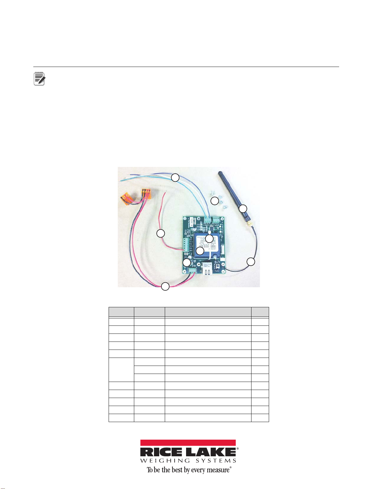
Figure 1. CLS-420/420Plus WLAN Option Kit
Item No Part No Description Qty
1 109266 Board Assy, Universal 1
2 112227 Module Wifi Matchport 1
3 112228 Cable RF UFL to RSMA 6in 1
4 118877 Cable Assy, Power Supply 1
5 14822 Screw, Mach 4-40NC x 1/4 4
6 15441 Wire, 20AWG Blue Stranded 1
May 06, 2014 152591 Rev A
15461 Wire, 20AWG White 1
15471 Wire, 20AWG Green Stranded 1
7 34181 Wire, 20AWG Red Stranded 1
8 58579 Strap, Tie 8 in Length 1
9 98357 Antenna, 2.4GHz 802.11B/G 1
21896 Label, Anti-Static Warning 1
72763 CD, Ethernet 1
Table 1. CLS-420/420Plus WLAN Option Kit Parts List
Page 2
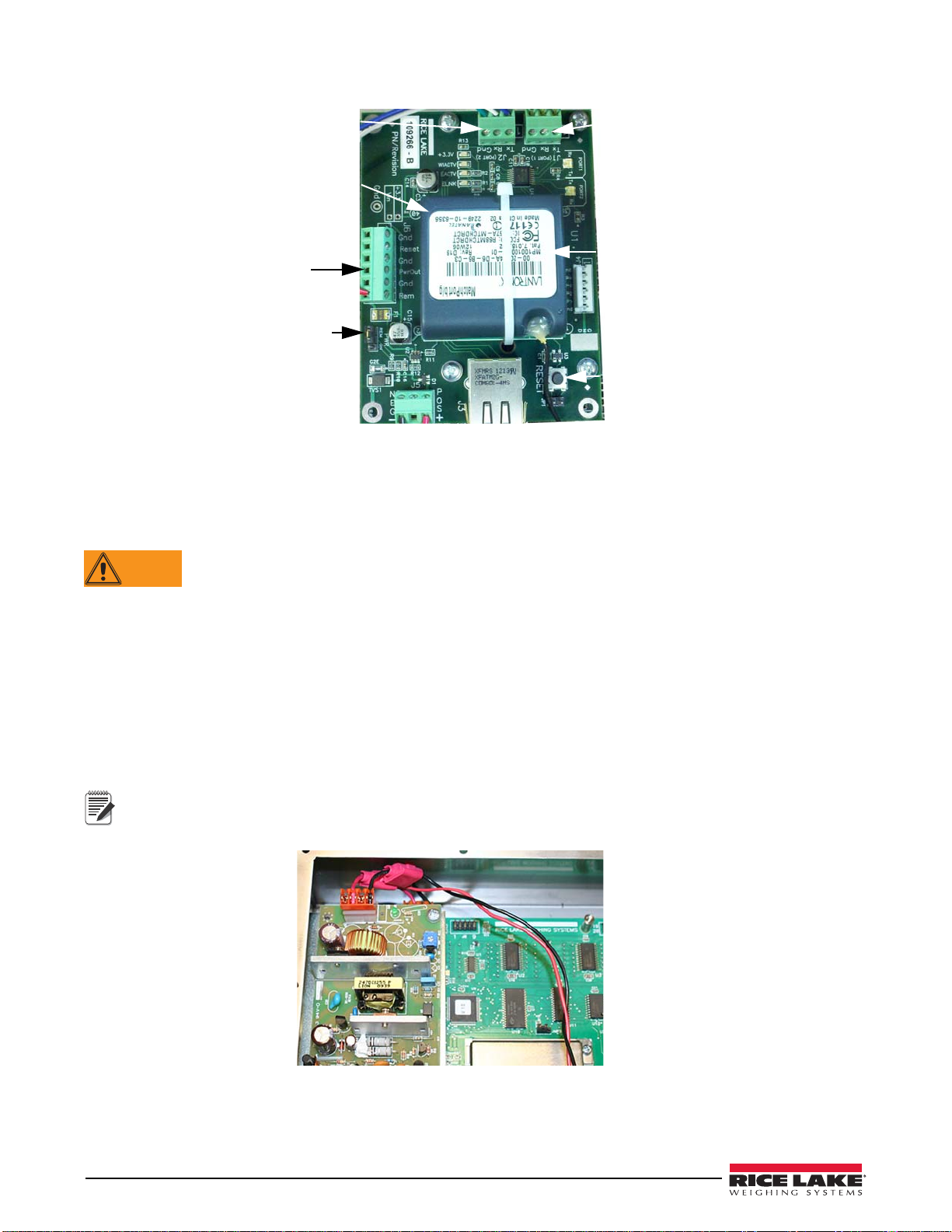
RS-232 Port 1
RS-232 Port 2
Port 1LED
Port 2 LED
GPIO Pins
Reset button
MatchPort module
CLS-420 J-Box
power out
Remote power on
Power jumper
Power input
5 to 9VDC
Ethernet
connector
MAC address
Figure 2. Universal MatchPort Option Card
WARNING
Note
Enclosure Disassembly
The indicator enclosure must be opened to install the WLAN option card and antenna, and to connect the wiring.
Before opening the unit, ensure the power cord is disconnected from the power source.
1. Disconnect power to the indicator
2. Place the indicator face-down on an anti-static work mat.
3. Remove the screws that hold the ba
4. Lift the backplate away from the enclos
ckplate to the enclosure body,
ure and set it aside.
Installing the Option Card
Installing the WLAN card as follows:
1. If installed, remove the plastic cover over the power supply (AC units).
2. Remove the two-wire cable that connects the power
If this is a CLS-420 installation, cut the red and black wires that lead to the 10-position connector on the
bottom of the enclosure as close as possible to the tap-and-run connectors. These t
attached to the option card. These wires are shown in Figure 3.
supply to the CPU board (discard).
wo wires will later be
2 CLS-420/420 Plus WLAN Installation Instructions
Figure 3. CLS-420 Installation Red and Black Wire Location
3. Place the option card, with the silver RJ-45 jack nearest to the indicator’s cord grips, on the four standoffs
located on the right side of the CPU board.
4. Line up the appropriate four holes and secure the board
with the included 4 x 40 screws.
Page 3
5. Route the power cable, which is already attached to the option card, to the power supply.
Note
Important
Note
Note
6. Attach the orange connector with only two wires to the CPU board J7.
7. Attach the other orange connector (with four wires), to the 4-pin connector on the power supply.
8. Re-install the plastic cover on t
If this is a CLS-420 installation, strip about a 1/4" of insulation from the red and black wires that were cut
earlier.
Attach the red wire to PWOUT connection of J6 on the option card and the black wire to the GND connection
next to the red wire. This will provide power to the CLS junction box.
he power supply, if applicable.
9. Attach the free end of the red wire coming from the option card to Pin 4 (+5V) of J6, using the 4-position
connector included in the parts kit that was supplied with the indicator. Verify PWR jumper on the option
board is in the REM position.
10. Decide which of the two 42
0 communication ports to attach to the WLAN option. If using the EDP port
(not available on the CLS-420), then connect the white, blue and green wires from the option card to pins 1,
2, and 3 (TxD, RxD, and GnD), respectively on J3. If using the PRN, or printer port, connect like above
except to J4.
Optionally, with the addition of three additional wires (not provided) connected to J1 (Port 1) of the WLAN
option, both the EDP and PRN ports can be connected to t
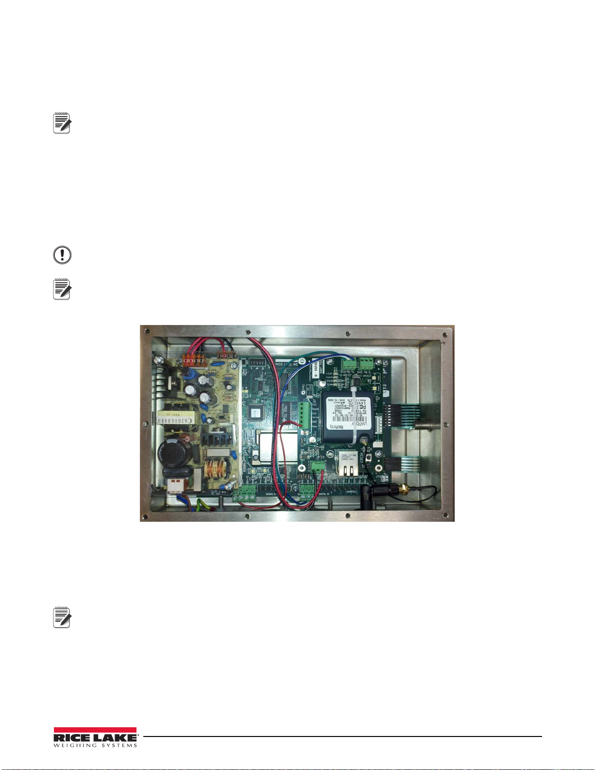
connection at this time as Port 1 is needed to perform the initial configuration of the option card.
For CLS-420 installations, if the 420 includes a 802.15 wireless load cell kit mounted to the rear of the
enclosure cover, to comply with FCC regulations, the antenna
802.15 wireless load cell kit module. Ensure the antenna is installed in the cord grip closest to the setup switch
access screw.
he WLAN option board. Do not make this
must be placed as far away as possible from the
Figure 4. WLAN Option Installed in 420 Indicator
Initial Configuration
Initial configuration must be performed using an RS-232 connection to a PC, and a terminal program, such as
Hyperterminal. After getting the option card to communicate with the network, Internet Explorer or DeviceInstaller
can be used for a more intuitive, graphical method of configuration to set the remainder of the card’s settings.
The configuration information should be all that is needed to establish a simple connection to most common
wireless networks. However, the MatchPort Device Ser
covered in this manual. For more detailed information regarding all the card’s settings and configuration
methods, please refer to the full MatchPort or WiPort
1. Connect a 3-wire RS-232 cable from the PC to J1 (Port 1) of the option card (shown in Figure 4). If using
a DB-9 connection on the PC, PC pin 2 will go to TX, pin 3 will go to RX, and pin 5 will go to GND.
2. Apply power to the 42
0 and turn it on. Verify the +3.3V LED lights on the WLAN option board. On the
PC, start the terminal program and set it for 9600 baud, 8 data bits, and no parity.
ver is powerful, and there are many settings not
™ 6
User Guides on the CD that is included with this kit.
3
Page 4

3. To initialize the configuration mode of the WLAN option card, press the x key on the keyboard three times
within three to five seconds after the option card’s power is applied, or it is reset. The easiest way to do this
is to:
• Press and hold the x key on the PC’s keyboard
• Then press and release the RESET button on the
option card.
• If done correctly, within a few seconds the option card will respond with its MAC address, its software
ve
rsion, and a message stating
• Relea
se the x key and press the enter key within five seconds to enter setup mode.
Press Enter for Setup Mode.
Figure 5. Connect Three Wires to Configure the Unit
Example:
MAC address 00204A04F598
Software version V6.8.0.2 (120903)
Press Enter for Setup Mode
After pressing enter, the option card will list all of its present settings, then display a list of up to nine options that
can be chosen.
At a minimum, the parameters in #0 (Server) and #4 (WLAN) will have to
set.
Setting the Initial Server Settings
To set the server settings:
1. Type
2. Choose if the card will be used as
3. If the current value is OK, press
4. Set the IP address. If using a Static IP addre
5. Set the Gateway. This can be set later
0, press enter.
a Wired Ethernet (0), or Wireless WLAN (1) interface. The current value
is shown in “()” just prior to the “?” prompt.
enter.
If not, key in the value, then press enter.
Example, if the current value is W
ired Only (0), to change to Wireless Only, key in “1” and press enter.
ss, enter the address one octet at a time.
Example, to enter 192.168.0.10:
• At the first octet type 192, then
• The second octet displays, type 168, then
• The third octet displays, type 0, then
• The fourth octet displays, type 10, then
enter.
enter.
enter.
enter.
If r network supports dynamic IP assignment (DHCP), the addres
on the DHCP mode in the Option Card).
• If the value in the “()” is okay, press
enter to advance.
, or not at all.
s to enter is 000.000.000.000 (this turns
4 CLS-420/420 Plus WLAN Installation Instructions
Page 5

6. Set the NetMask. If using DHCP, set this to 0.
Note
Important
Note
• For 255.255.255.0, enter 8.
• For 255.255.0.0, enter 16.
• For 255.0.0.0, enter 24.
7. The next several settings are usually r
equired to be default, unless changes are required, just enter through
them until the nine choices reappear.
Setting the Initial WLAN Settings
1. The WLAN settings need to be set, if Wireless Only is selected. Select configuration option 4.
2. Set the Topology. Select the network type and press
• AdHoc – only two devices that talk
to each other. Refer to the Lantronix user guides on the CD.
• Infrastructure – connecting to an Access Point on a larger network.
Infrastructure networks are more common, and will be used for this setup example.
3. Set the Network Name, or SSID. Enter the name and press enter. It is case-sensitive.
4. Set the Security Suite.
• If there is an open network, select 0.
• If there is WEP, WPA, or WPA2 security, selec
These settings are critical for allowing the Option Card to connect to the network. If any settings are not
understood, seek help from the network administrato
enter.
t the appropriate type and hit enter.
r, or the included User Guides on the CD.
The following parameters vary depending on the choices made. Set all the parameters as needed.
5. There are several other settings regarding the data rates, power management, and roaming. Default should
be acceptable, but they can be changed if needed.
6. Now the option card should be able to establi
enter to save the configuration settings and leave setup mode.
7. The option card will save the changes, then re-boot
sh communications with the WLAN network. Type 9 and
. Watch the WIACTV LED on the card, the LED will
blink while it is searching for the network.
• If finds and successfully connects to the network,
• If it cannot find the network, or finds it, but cannot connect due
the LED will be lit solid.
to configuration setting problems, the
LED will continue to blink, or go off. If this happens, start over with the RS-232 configuration method,
correcting the setting(s) that is causing the problem.
Other Configuration Settings
The card’ s configuration settings can be made using th e RS-232 method, bu t it is much easier to use a web browser
or DeviceInstaller to do it.
DeviceInstaller is provided on the CD
network to remotely configure any of the Lantronix Device Servers it finds on the network. When opened,
DeviceInstaller will search the network for all available devices. Select the device by MAC or IP. Once selected,
configure all the card’s settings, as well as upgrade its firmware. More information regarding DeviceInstaller is
available on the CD.
The other method to configure the card is using a web browser
enter the option card’s IP address in the browser address bar. The browser will open a web server, using port 80, on
the option card. From here, using this method is much the same as configuration through DeviceInstaller. Please
refer to the CD for more information.
included with this kit. It can be installed on a computer that is part of the
, such as Internet Explorer or Firefox
® 7
. Simply
5
Page 6

Establishing Communication With the 420
1
6
9
4
2
5
7
10
Torque Pattern
8
3
Important
Important
The option card has two TCP Ports that can be used to communicate. Default is TCP Ports 10001 (Port 1) and
10002 (Port 2). These numbers can be changed in the option card, if needed. Port 1 and Port 2 refer to the physical
connection on the option card. If installed as instructed, J2 (Port 2) is connected to either the EDP or PRN port on
the420 indicator. J1 (Port 1) was used for configuration. If using Port 1 to talk to the ‘other’ RS-232 port on the
420, it can be wired it at this time.
The default RS-232 communications settings on the option card are 96
00, 8N1, and should match the default
settings in the 420. If not, make the necessary changes in the 420, or the option card Channel 1 or 2 (port 1 or 2) so
they match.
To open a connection, start the PC Communications software and open a
TCP/IP connection to the IP address
assigned to the card (with the static IP that was configured, or the DHCP IP assigned by the network), and the port
number for the ‘Port’ on the option card to be talked through (by default, this will be 10002, or Port 2).
Once open, communication i
s established to the 420 the same as if wired to an RS-232 connection.
Other Options
By default, it will take an external device or program to establish a communications connection to the option card
in the 420. However, the option card is also capable of initiating the connection to another device or PC listening
on a port.
In the serial settings for the RS-232 channel are using, there are settings to open an active connection. By defaul
this is off. To use the 420 to open a connection, the active connection parameter can be set to something other than
None, such as “With Any Character,” the remote host IP and Port values will have to be set. This setting will open
a connection to a remote host as soon as any character is sent from the 420 to the option card. This could be useful
for printing to a remote printer, streaming to a remote display, or sending data to a PC program.
There is wide variety of possible configuration settings, refer to the user gu
ides include on the CD, or call our
technical or sales support staff with the particular application and questions.
t,
Enclosure Reassembly
Once installation of the option card is complete:
1. Position the backplate over the enclosure and
2. Reinstall the backplate screws.
Use the torque pattern shown in Figure 5 to prevent distorting the backplate gasket. Torque screws to 15
in-lb. (1.7 N-m).
Torqued screws may become less tight as the gasket is compressed during torque pattern, therefore a
second torque is required using the same
Figure 6. 420 Enclosure Backplate
pattern and torque value.
6 CLS-420/420 Plus WLAN Installation Instructions
Page 7

MatchPort Wireless Specifications
Category IEEE 802.11b/g
Frequency Range 2.400 - 2.484 GHz
Output Power 14 +2.0/-1.5 dBm 1, 2, 5.5, 11 Mbps
12 +/- 1.5 dBm 6, 9, > 12 Mbps
Antenna Connector 1
Data Rates 1, 2, 5.5, 11, 6, 9, 12, 18, 24, 36, 48, 54 Mbps
Radio Number of selectable
subchannels
Modulation DSSS, DBPSK, DQPSK, CCK, OFDM, 16QAM, 64QAM
Antenna connector 1
Security WEP 64/128, WPA, WPA2/802, 11i
Maximum Receive Level -10 dBm (with PER < 8%)
Receiver Sensitivity -69 dBm for 54 Mbps
WLAN Current Max: 10 mA
US 1-11
CA 1-11
JP 1-14
FR 10-13
SP 10-13
OT 1-13 (OT = others)
-88 dBm for 11 Mbps
-85 dBm for 6 Mbps
-91 dBm for 1.0 Mbps
Table 2. Wireless Specifications
1. Lantronix® is a registered trademark of Lantronix, Inc.
2. MatchPort
3. HyperTerminal is a registered trademark of Hilgraeve, Inc.
4. Internet Explorer
5. DeviceInstaller
6. WiPort
7. Firefox
®
is a registered trademark of Lantronix, Inc.
®
is a registered trademark of Microsoft Corporation
TM
is a trademark of Lantronix, Inc.
®
is a registered trademark of Lantronix, Inc.
®
is a registered trademark of Mozilla Foundation
7
Page 8

230 W. Coleman St. • Rice Lake, WI 54868 • USA
U.S. 800-472-6703 • Canada/Mexico 800-321-6703 • International 715-234-9171 • Europe +31 (0) 88 2349171
www.ricelake.com www.ricelake.mx www.ricelake.eu www.ricelake.co.in m.ricelake.com
Disclaimer
Note
Note
This equipment has been tested and found to comply with the limits for a Class B digital device, pursuant to Part 15
of the FCC Rules. These limits are designed to provide reasonable protection against harmful interference in a
residential installation. This equipment generates, uses, and can radiate radio frequency energy and, if not installed
and used in accordance with the instructions, may cause harmful interference to radio communications. However,
there is no guarantee that interference will not occur in a particular installation. If this equipment does cause
harmful interference to radio or television reception, which can be determined by turning the equipment of f and on,
the user is encouraged to try to correct the interference by one of the following measures:
• Reorient or relocate the receiving antenna.
• Increase the separation between the equipment and receiver.
• Connect the equipment into an outlet on a circuit dif
• Consult the dealer or an experienced
This device complies with Part 15 of the FCC
radio/TV technician for help.
Rules. Operation is subject to the following two conditions: (1) This
device may not cause harmful interference, and (2) this device must accept any interference received, including
interference that may cause undesired operation.
This device is intended only for OEM
Integrators. The OEM integrator should be aware of the following important
issues.
Labeling of the End Product
The label on the end product incorporating the MatchPort b/g module must clearly state that it contains an
FCC-approved RF module. For example, This product contains an RF transmitter ID# R68MTCHDRCT.
RSS-GEN Sections 7.1.4 and 7.1.5 Statement for
Devices with Detachable Antennas
This device has been designed to operate with the antennas listed
5 dBi. Antennas not included in this list or having a gain greater than 5 dBi are strictly prohibited for use with this
device, unless system-level FCC approval is gained. The required antenna impedance is 50 ohms.
To reduce potential radio interference to
other users, the antenna type and its gain should be so chosen that the
equivalent isotropically radiated power (EIRP) is not more than that required for successful communication.
ferent from that to which the receiver is connected.
in the Certificate, and having a maximum gain of
Integration Note
This module is authorized under limited module approval specified to mobile host equipment. So, the antenna must
be installed such that 20cm is maintained between the antenna and users.
The transmitter module may not be co-located with any other transmitte
As long as the two conditions above are met, further transmitt
er testing will not be required. However, the OEM
r or antenna.
integrator is still responsible for testing their end product for any additional compliance requirements required with
this module installed (for example, digital device emission, PC peripheral requirements, etc.)
In the event that these conditions cannot be met (for example certain laptop configurations, general purpose
PCMCIA or similar cards, or co-location with another t
considered valid and the FCC ID cannot be used on the final product (including the transmitter) and obtaining
a separate FCC authorization.
Changes or modifications to this device not explicitly approved by Lantronix will void the user's authority
operate this device.
ransmitter), then the FCC authorization is no longer
to
© Rice Lake Weighing Systems 05/2014 PN 152591 Rev A
 Loading...