

Page 1
CB-2
Automated Concrete Batching System
Version 2.0
Installation/Operation Manual
93603
Page 2

Page 3

Contents
Technical training seminars are available through Rice Lake Weighing Systems.
Course descriptions and dates can be viewed at www.ricelake.com/training
or obtained by calling 715-234-9171 and asking for the training department.
About This Manual ....................................................................................................................................1
Safety ........................................................................................................................................... 1
1.0 Introduction.................................................................................................................................. 2
1.1 Operating Modes . . . . . . . . . . . . . . . . . . . . . . . . . . . . . . . . . . . . . . . . . . . . . . . . . . . . . . . . . . . . . . . 3
1.2 Indicator Operations . . . . . . . . . . . . . . . . . . . . . . . . . . . . . . . . . . . . . . . . . . . . . . . . . . . . . . . . . . . . 4
2.0 Installation ................................................................................................................................... 5
2.1 Important Notes . . . . . . . . . . . . . . . . . . . . . . . . . . . . . . . . . . . . . . . . . . . . . . . . . . . . . . . . . . . . . . . . 6
2.1.1 Two Power Sources . . . . . . . . . . . . . . . . . . . . . . . . . . . . . . . . . . . . . . . . . . . . . . . . . . . . . . . . . . . . . . . 6
2.1.2 I/O Power and Manual Panel Same Phase Power . . . . . . . . . . . . . . . . . . . . . . . . . . . . . . . . . . . . . . . . . 6
2.1.3 Unused Inputs Must be Jumpered to 120V . . . . . . . . . . . . . . . . . . . . . . . . . . . . . . . . . . . . . . . . . . . . . . 6
2.2 CB-2 Main Junction Block . . . . . . . . . . . . . . . . . . . . . . . . . . . . . . . . . . . . . . . . . . . . . . . . . . . . . . . . 7
2.3 Load Cells . . . . . . . . . . . . . . . . . . . . . . . . . . . . . . . . . . . . . . . . . . . . . . . . . . . . . . . . . . . . . . . . . . . . 8
2.3.1 Serial Communications . . . . . . . . . . . . . . . . . . . . . . . . . . . . . . . . . . . . . . . . . . . . . . . . . . . . . . . . . . . . 10
2.4 Digital I/O . . . . . . . . . . . . . . . . . . . . . . . . . . . . . . . . . . . . . . . . . . . . . . . . . . . . . . . . . . . . . . . . . . . . 12
2.5 Battery Replacement . . . . . . . . . . . . . . . . . . . . . . . . . . . . . . . . . . . . . . . . . . . . . . . . . . . . . . . . . . . 15
2.6 Replacement Parts. . . . . . . . . . . . . . . . . . . . . . . . . . . . . . . . . . . . . . . . . . . . . . . . . . . . . . . . . . . . . 16
2.6.1 Option Cards. . . . . . . . . . . . . . . . . . . . . . . . . . . . . . . . . . . . . . . . . . . . . . . . . . . . . . . . . . . . . . . . . . . . 16
2.7 Installing an Optional PS-2 Keyboard . . . . . . . . . . . . . . . . . . . . . . . . . . . . . . . . . . . . . . . . . . . . . . 17
3.0 Configuration of Scale Parameters ........................................................................................... 18
3.1 Configuration Methods . . . . . . . . . . . . . . . . . . . . . . . . . . . . . . . . . . . . . . . . . . . . . . . . . . . . . . . . . 18
3.1.1 iRev Configuration . . . . . . . . . . . . . . . . . . . . . . . . . . . . . . . . . . . . . . . . . . . . . . . . . . . . . . . . . . . . . . . 18
3.1.2 Front Panel Configuration . . . . . . . . . . . . . . . . . . . . . . . . . . . . . . . . . . . . . . . . . . . . . . . . . . . . . . . . . . 19
3.2 Menu Structures and Parameter Descriptions . . . . . . . . . . . . . . . . . . . . . . . . . . . . . . . . . . . . . . . 20
3.2.1 SCALES Menu . . . . . . . . . . . . . . . . . . . . . . . . . . . . . . . . . . . . . . . . . . . . . . . . . . . . . . . . . . . . . . . . . . 21
4.0 Configuration of User Parameters ............................................................................................. 22
4.1 Application Parameters . . . . . . . . . . . . . . . . . . . . . . . . . . . . . . . . . . . . . . . . . . . . . . . . . . . . . . . . . 23
5.0 Calibration ................................................................................................................................. 40
5.1 Gravity Compensation . . . . . . . . . . . . . . . . . . . . . . . . . . . . . . . . . . . . . . . . . . . . . . . . . . . . . . . . . . 40
5.2 Front Panel Calibration . . . . . . . . . . . . . . . . . . . . . . . . . . . . . . . . . . . . . . . . . . . . . . . . . . . . . . . . . 40
5.3 Serial Command Calibration . . . . . . . . . . . . . . . . . . . . . . . . . . . . . . . . . . . . . . . . . . . . . . . . . . . . . 41
5.4 iRev Calibration . . . . . . . . . . . . . . . . . . . . . . . . . . . . . . . . . . . . . . . . . . . . . . . . . . . . . . . . . . . . . . . 42
6.0 Utilities....................................................................................................................................... 44
6.1 Material Usage . . . . . . . . . . . . . . . . . . . . . . . . . . . . . . . . . . . . . . . . . . . . . . . . . . . . . . . . . . . . . . . . 46
6.1.1 Usage Reports . . . . . . . . . . . . . . . . . . . . . . . . . . . . . . . . . . . . . . . . . . . . . . . . . . . . . . . . . . . . . . . . . . 47
6.1.2 Adjust Inventory . . . . . . . . . . . . . . . . . . . . . . . . . . . . . . . . . . . . . . . . . . . . . . . . . . . . . . . . . . . . . . . . . 47
6.1.3 Clear Day Totals through Yearly Totals . . . . . . . . . . . . . . . . . . . . . . . . . . . . . . . . . . . . . . . . . . . . . . . . 47
6.2 Tune Plant. . . . . . . . . . . . . . . . . . . . . . . . . . . . . . . . . . . . . . . . . . . . . . . . . . . . . . . . . . . . . . . . . . . . 48
6.2.1 Min. Drop Screen . . . . . . . . . . . . . . . . . . . . . . . . . . . . . . . . . . . . . . . . . . . . . . . . . . . . . . . . . . . . . . . . 49
6.2.2 Tune Jogs Screen . . . . . . . . . . . . . . . . . . . . . . . . . . . . . . . . . . . . . . . . . . . . . . . . . . . . . . . . . . . . . . . . 50
6.3 Reports . . . . . . . . . . . . . . . . . . . . . . . . . . . . . . . . . . . . . . . . . . . . . . . . . . . . . . . . . . . . . . . . . . . . . . 50
6.3.1 Print Mix Designs . . . . . . . . . . . . . . . . . . . . . . . . . . . . . . . . . . . . . . . . . . . . . . . . . . . . . . . . . . . . . . . . 51
6.3.2 Print Application Parameters . . . . . . . . . . . . . . . . . . . . . . . . . . . . . . . . . . . . . . . . . . . . . . . . . . . . . . . . 51
6.3.3 Print Diagnostics . . . . . . . . . . . . . . . . . . . . . . . . . . . . . . . . . . . . . . . . . . . . . . . . . . . . . . . . . . . . . . . . . 51
Rice Lake Weighing Systems. All rights reserved. Printed in the United States of America.
Specifications subject to change without notice. Rice Lake Weighing Systems is an ISO 9001 registered company.
Version 2.0 November 2013
Page 4

6.4 Diagnostics . . . . . . . . . . . . . . . . . . . . . . . . . . . . . . . . . . . . . . . . . . . . . . . . . . . . . . . . . . . . . . . . . . 51
Rice Lake continually offers web-based video training on a growing selection
of product-related topics at no cost. Visit www.ricelake.com/webinars.
6.4.1 Test Inputs . . . . . . . . . . . . . . . . . . . . . . . . . . . . . . . . . . . . . . . . . . . . . . . . . . . . . . . . . . . . . . . . . . . . . 52
6.4.2 Test Outputs. . . . . . . . . . . . . . . . . . . . . . . . . . . . . . . . . . . . . . . . . . . . . . . . . . . . . . . . . . . . . . . . . . . . 53
6.4.3 Test Ticket Printer. . . . . . . . . . . . . . . . . . . . . . . . . . . . . . . . . . . . . . . . . . . . . . . . . . . . . . . . . . . . . . . . 54
6.4.4 Test Report Printer . . . . . . . . . . . . . . . . . . . . . . . . . . . . . . . . . . . . . . . . . . . . . . . . . . . . . . . . . . . . . . . 54
6.4.5 Test Serial Ports . . . . . . . . . . . . . . . . . . . . . . . . . . . . . . . . . . . . . . . . . . . . . . . . . . . . . . . . . . . . . . . . . 54
6.4.6 Print Diagnostics. . . . . . . . . . . . . . . . . . . . . . . . . . . . . . . . . . . . . . . . . . . . . . . . . . . . . . . . . . . . . . . . . 54
6.4.7 Clear Diagnostics . . . . . . . . . . . . . . . . . . . . . . . . . . . . . . . . . . . . . . . . . . . . . . . . . . . . . . . . . . . . . . . . 54
7.0 EZ Change Criticals ................................................................................................................... 55
8.0 Batching ..................................................................................................................................... 56
9.0 Front Panel................................................................................................................................. 58
9.1 Front Panel Description . . . . . . . . . . . . . . . . . . . . . . . . . . . . . . . . . . . . . . . . . . . . . . . . . . . . . . . . 58
9.1.1 Power Control. . . . . . . . . . . . . . . . . . . . . . . . . . . . . . . . . . . . . . . . . . . . . . . . . . . . . . . . . . . . . . . . . . . 58
9.1.2 Auxiliary Control . . . . . . . . . . . . . . . . . . . . . . . . . . . . . . . . . . . . . . . . . . . . . . . . . . . . . . . . . . . . . . . . . 58
9.1.3 Aggregate Control . . . . . . . . . . . . . . . . . . . . . . . . . . . . . . . . . . . . . . . . . . . . . . . . . . . . . . . . . . . . . . . 59
9.1.4 Cement Control . . . . . . . . . . . . . . . . . . . . . . . . . . . . . . . . . . . . . . . . . . . . . . . . . . . . . . . . . . . . . . . . . 59
9.1.5 Mixer Control . . . . . . . . . . . . . . . . . . . . . . . . . . . . . . . . . . . . . . . . . . . . . . . . . . . . . . . . . . . . . . . . . . . 59
9.1.6 Plant Control. . . . . . . . . . . . . . . . . . . . . . . . . . . . . . . . . . . . . . . . . . . . . . . . . . . . . . . . . . . . . . . . . . . . 59
9.1.7 Water Control . . . . . . . . . . . . . . . . . . . . . . . . . . . . . . . . . . . . . . . . . . . . . . . . . . . . . . . . . . . . . . . . . . . 59
9.1.8 Admixture Control. . . . . . . . . . . . . . . . . . . . . . . . . . . . . . . . . . . . . . . . . . . . . . . . . . . . . . . . . . . . . . . . 59
10.0 Appendix .................................................................................................................................... 60
10.1 Configuration Parameters for the CB-2 Weighed Materials Discharged Using an Inch Gate . 60
10.2 Configuration Parameters for CB-2 Weighed Materials Discharged Using an Open Close Gate.
61
10.3 Weighing Material Preact Configuration Parameters. . . . . . . . . . . . . . . . . . . . . . . . . . . . . . . . . 62
10.3.1 Preacts - Hopper Scale. . . . . . . . . . . . . . . . . . . . . . . . . . . . . . . . . . . . . . . . . . . . . . . . . . . . . . . . . . . . 62
10.3.2 Preacts - Decumulative Scale . . . . . . . . . . . . . . . . . . . . . . . . . . . . . . . . . . . . . . . . . . . . . . . . . . . . . . . 63
10.3.3 EZ Change Criticals - Material Preacts . . . . . . . . . . . . . . . . . . . . . . . . . . . . . . . . . . . . . . . . . . . . . . . . 63
10.3.4 Preact Value Level When Used in Lose in Weight (LIW). . . . . . . . . . . . . . . . . . . . . . . . . . . . . . . . . . . . 63
10.4 Entering a Mix Design . . . . . . . . . . . . . . . . . . . . . . . . . . . . . . . . . . . . . . . . . . . . . . . . . . . . . . . . . 63
10.4.1 To Add a Mix Design. . . . . . . . . . . . . . . . . . . . . . . . . . . . . . . . . . . . . . . . . . . . . . . . . . . . . . . . . . . . . . 64
10.5 CB-2 Moisture Probe . . . . . . . . . . . . . . . . . . . . . . . . . . . . . . . . . . . . . . . . . . . . . . . . . . . . . . . . . . 65
10.6 Changing the Location of a Material. . . . . . . . . . . . . . . . . . . . . . . . . . . . . . . . . . . . . . . . . . . . . . 66
10.7 Dual Speed and Dual Concurrent Settings. . . . . . . . . . . . . . . . . . . . . . . . . . . . . . . . . . . . . . . . . 67
10.8 Error Messages . . . . . . . . . . . . . . . . . . . . . . . . . . . . . . . . . . . . . . . . . . . . . . . . . . . . . . . . . . . . . . 69
10.9 CB-2 Loss In Weight Inching Gate . . . . . . . . . . . . . . . . . . . . . . . . . . . . . . . . . . . . . . . . . . . . . . . 73
10.10 CB-2 Loss In Weight Open/Close . . . . . . . . . . . . . . . . . . . . . . . . . . . . . . . . . . . . . . . . . . . . . . . 74
10.11 MNDot Conversion. . . . . . . . . . . . . . . . . . . . . . . . . . . . . . . . . . . . . . . . . . . . . . . . . . . . . . . . . . . 75
10.12 Moisture Specifications . . . . . . . . . . . . . . . . . . . . . . . . . . . . . . . . . . . . . . . . . . . . . . . . . . . . . . . 77
10.12.1 Cement/Water/Aggregate Mix Specifications . . . . . . . . . . . . . . . . . . . . . . . . . . . . . . . . . . . . . . . . . . . 77
10.12.2 Oven Dry vs. Saturated Surface Dry Mix Designs . . . . . . . . . . . . . . . . . . . . . . . . . . . . . . . . . . . . . . . . 77
10.12.3 Example of Weight Adjustments Based on a Saturated Surface Dry Mix Design . . . . . . . . . . . . . . . . . 77
10.12.4 Calculating Aggregate Moisture Content. . . . . . . . . . . . . . . . . . . . . . . . . . . . . . . . . . . . . . . . . . . . . . . 78
10.12.5 Specifying Moisture Content and Absorption Factors . . . . . . . . . . . . . . . . . . . . . . . . . . . . . . . . . . . . . 78
10.12.6 Calibrating a Moisture Probe. . . . . . . . . . . . . . . . . . . . . . . . . . . . . . . . . . . . . . . . . . . . . . . . . . . . . . . . 78
10.13 Reservoir Metered Water. . . . . . . . . . . . . . . . . . . . . . . . . . . . . . . . . . . . . . . . . . . . . . . . . . . . . . 78
10.14 Tuning Inching Gates . . . . . . . . . . . . . . . . . . . . . . . . . . . . . . . . . . . . . . . . . . . . . . . . . . . . . . . . . 79
10.15 Setting up Time & Date Formats . . . . . . . . . . . . . . . . . . . . . . . . . . . . . . . . . . . . . . . . . . . . . . . . 81
10.16 CB-2 Administrative Codes . . . . . . . . . . . . . . . . . . . . . . . . . . . . . . . . . . . . . . . . . . . . . . . . . . . 82
10.17 Adding Counter and Position Indicators. . . . . . . . . . . . . . . . . . . . . . . . . . . . . . . . . . . . . . . . . . 83
2 CB-2 Installation Manual
Page 5
About This Manual
WARNING
WARNING
WARNING
Important
CAUTION
WARNING
This manual is intended for use by service technicians responsible for installing and servicing the CB-2 and the
end user who will be operating the CB-2 automated concrete batching system.
In this manual, you will see many references to the CB-2 and
panel that includes Rice Lake’s 920i
®
HMI digital weight indicator. The 920i is the heart and brain of the CB-2
the 920i. To clarify, the CB-2 is a stand-alone batch
and is responsible for weight/scale data as well as running the CB-2 batching program. The CB-2 also contains
additional hardware that is interfaced to the 920i. The majority of the additional hardware is for controlling the
batch plant through digital I/O and then through solid-state 120V/240V relay modules.
Some procedures described in this
manual require work inside the
losure. These procedures are to be
enc
performed by qualified service
personnel only.
Authorized distributors and their employees
can view or download this manual from the
Rice Lake Weighing Systems distributor site
at www.ricelake.com.
Safety
Safety Symbol Definitions
Indicates a potentially hazardous situation that, if not avoided, could result in serious injury or death,
and includes hazards that are exposed when guards are removed.
Indicates a potentially hazardous situation that, if not avoided may result in minor or moderate injury.
Indicates information about procedures that, if not observed, could result in damage to equipment or
corruption to and loss of data.
Safety Precautions
Do not operate or work on this equipment unless you have read and understand the instructions and
warnings in this manual. Failure to follow the instructions or heed the warnings could result in injur
or death. Contact any Rice Lake Weighing Systems dealer for replacement manuals. Proper care is
your responsibility.
Some procedures described in this manual require work inside the indicator enclosure. These
procedures are to be performed by qualified service personnel only.
General Safety
Failure to heed may result in serious injury or death.
DO NOT allow minors (children) or inexper
DO NOT use for purposes other than weight taking.
DO NOT place fingers into slots or possible pinch points.
DO NOT use any load-bearing component that is wo
DO NOT use this product if any of the
DO NOT exceed the rated load limit of the unit.
DO NOT make alterations or modifications to the unit.
DO NOT remove or obscure warning labels.
DO NOT use near water.
Before opening the unit, ensure the power cord
Keep hands, feet and loose clothing
ienced persons to operate this unit.
rn beyond 5% of the original dimension.
components are cracked.
is disconnected from the outlet.
away from moving parts.
y
Installation/Operation Manual - Safety 1
Page 6

1.0 Introduction
The CB-2 is a versatile, efficient concrete batching control system ideal for ready-mix, central mix, and block
plants. The CB-2 makes it easy and affordable to streamline your plant. From weighing raw material to automatic
printing of tickets and reports, the entire operation can be cost-effectively controlled from this one controller.
iRev provides functions for installing the new software into the CB-2.
Standard Features - Hardware
Standard hardware features of the CB-2 include:
• Panel type 920i HMI digital indicator that can
control up to three scales
• Six totalizing counters for units with admix
metering
• One addition totalizing counter for units with
metered water
• Twenty switch board assemblies with their
associated switches and appropriate
annunicators which are mounted on the front
panel of the CB-2 enclosure
• 920i expansion card with 1MB of memory
• Four digital I/O boards
• 4 - 24 channel relay boards
• Standard manual override controls
Standard Features - Software
Standard software features of the CB-2 include the
following:
• One aggregate and one cement scale sampling
60 times per second
• Batch/Load report
• Automatic aeration control for cement silos
and weigh hoppers
• Multiple free fall values per material with
automatic “learning” abilities
• Split batching for loads larger than plant
capacity with pre-weighing next batch for
maximum throughput
• Automatic dust collection outputs
• Precision control of inching gates for
aggregate and cement discharge
• Passcode protection
• U.S. or metric units
• Order loading with customer, job site, directions,
and special instructions
2 Installation/Operation Manual
Page 7
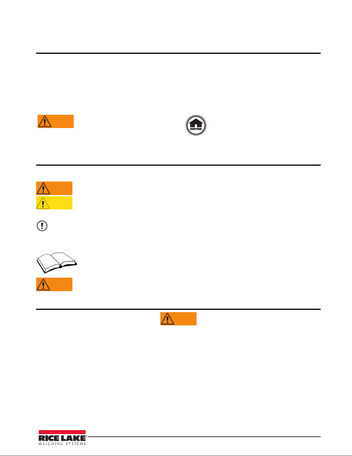
Front Panel
The 920i front panel, shown in Figure 1-1, consists of a 27-button keypad with a large backlit LCD display. The
keys are grouped as five configurable softk
eys, five primary scale function keys, four navigation keys, and
numeric entry keys.
Two scale widgets can be displayed in standard metered water
applications. Status areas on the display are used
for operator prompts and entering data. Display contrast can be adjusted with the LCD contrast potentiometer.
Figure 1-1. 920i Front Panel
1.1 Operating Modes
The 920i in the CB-2 automated concrete batching
system has two basic modes of operation:
Normal mode
Normal mode is the weighing mode of the
indicator. The CB-2 “program” only executes in
Normal Mode. The weight is only displayed in
Normal Mode. Once configuration is complete
and a legal seal is affixed to the large fillister-head
screw on the indicator enclosure, this is the only
mode in which the
When in Normal Mode, the
always show softkeys. The operator’s interaction
will be driven by softkey selections. As softkeys
are collectively named in the Main Menu. On the
far right of the main menu is the “Admin Menu”
softkey. The Admin Menu may be passcode
protected. The Admin Menu is where all
configuration and database entry takes place. A
large portion of this manual is dedicated to
explaining the categories and individual settings
in the Admin Menu.
920i can operate.
CB-2 program will
nfiguration Mode) is entered by pressing the
Co
setup switch. Setup Mode will be used during the
initial installation of the CB-2. Calibration of the
scales, configuration of filtering and motion band,
and upgrading the CB-2 software are some of the
important tasks that require the indicator to be in
Setup Mode. Once the CB-2 has been installed
and calibrated, there will probably be only three
reasons to ever enter Setup Mode again;
• Annual service calibration of scales
• Adding a PS/2 keyboard
• Upgrading the CB-2 software
Section 3 of this manual explains the Scale
configurati
on and calibration while in Setup
Mode.
To enter setup mode, remove the l
arge fillister
head screw from the enclosure. Insert a
screwdriver or a similar tool into the access hole
and press the setup switch once. The indicator
display changes to show scale configuration
menus.
Setup mode
A few of the procedures described in this manual
require the indicator to be in setup mode,
including configuration and calibration.
Setup Mode (sometimes referred to as
Installation/Operation Manual - Introduction 3
Page 8

1.2 Indicator Operations
The CB-2 does not allow the 920i to execute any of its standard operations like Gross/Net, Units, Print, Tare, and
Zero because they are not applicable to this application. In other words, the Gross/Net, Tare, Units, and Print
keys are disabled all the time. The Zero key is allowed at times during the loading process and while no load is
batching.
Zero Scale Process
Because the CB-2 always has two or more scales, the zeroing of the scale is a three-step process. Only the scale
that is selected can be zeroed. There are two ways to tell which scale is selected. First, the top weight widget will
show Scale #1 and display the current weight in/on scale #1 when scale # 1 is selected. It will show Scale #2 if
cement scale is selected and so on. Also, the selected scale # is displayed in the upper right hand corner of the
display.
Remember that the scale assignments will always be:
Aggregate Scale 1
Cement Scale 2
Water Scale 3
Example: To zero the cement scale;
1. Press the Zero key. If zeroing is not allowed at this time, you will be informed. If zeroing is allowed, the
message “Up/Down nav keys are enabled” is displayed.
2. Press the down arrow key until scale 2 (the cement scale) is shown in the top weight widget and in the
upper righthand corner of the display.
3. Press the zero key again. If the 920i allows the zero command, then the selected scale (scale 2, the
cement scale), should now read zero. The CB-2 automatically puts the aggregate scale (scale #1) back in
the top widget and redraws the text AGG, CEM, next to the appropriate weight widgets.
4 Installation/Operation Manual
Page 9
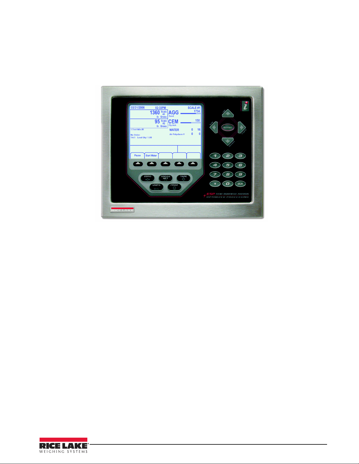
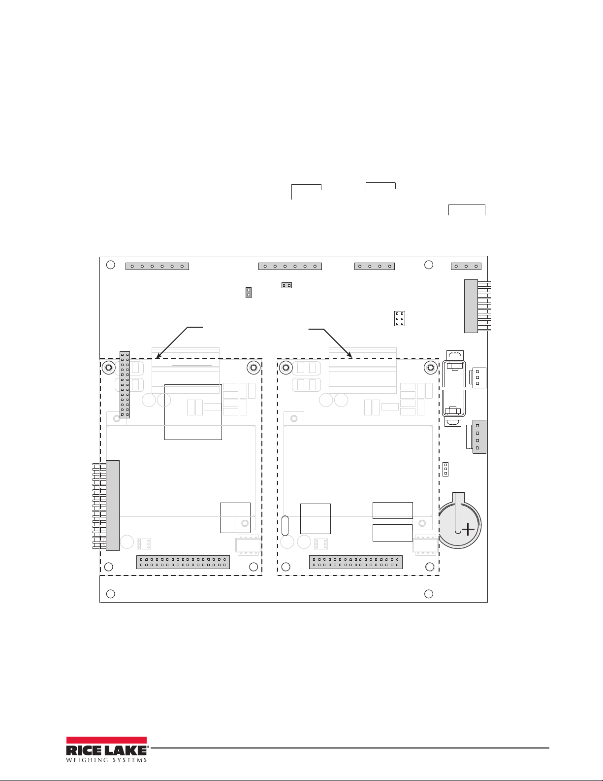
2.0 Installation
Expansion Board
Breakout Boards
Terminal Blocks
Relay Racks
Agg Conveyor and Air
Compressor Latching
Relay Circuits
WARNING
This section explains the main junction box, load cell, digital I/O, and serial communications connections located
inside of the CB-2. The 920i HMI indicator is housed inside the CB-2 enclosure which is shown below in
Figure 2-1 along with examples of several oth
er key component parts.
Figure 2-1. CB-2 Enclosure
• Use a wrist strap to ground yourself and protect components from electrostatic discharge (ESD) when
working inside the indicator enclosure.
• This unit uses double pole/neutral fusing which could create
an electric shock hazard. Procedures
requiring work inside the indicator must be performed by qualified service personnel only.
• The supply cord serves as the power disconnect
for the 920i. The power outlet supplying the indicator
must be installed near the unit and be easily accessible.
Installation/Operation Manual - Installation 5
Page 10

2.1 Important Notes
2.1.1 Two Power Sources
The CB-2 requires two separate power sources to run. The power cord that came wired to your CB-2 ONLY
powers the electronics. This power should come from a quality UPS with power conditioning. This clean power
must be separated as far as possible (distance in the electrical circuit) from the power source used to power the
motion control on the batch plant.
Another power source must be brought into the CB-2 to power the I/O (output relays), that control the plant. No
power cord is supplied because this power must be brought directly from its own circuit or fed from another
manual panel.
2.1.2 I/O Power and Manual Panel Same Phase Power
The CB-2 and manual panel will both be wired to the same I/O points for most plant controls (exceptions are air
compressors or other equipment the CB-2 doesn’t control in automatic mode). Because of this, it is critical that
the 120V “hot” that is used for the CB-2 I/O power, is the same “hot” phase used by the manual panel.
2.1.3 Unused Inputs Must be Jumpered to 120V
The CB-2 uses 120V input signals from various sensors for positive and negative feedback. At a minimum, the
CB-2 requires the following signals:
• Cement discharge gate closed (Terminal 4-13 - Rack 2, Point 7)
• Aggregate discharge gate closed (Terminal 4-15 - Rack 2, Point 8)
• Aggregate conveyor running (Terminal 4-9 - Rack 2, Point 5)
• E-Stop not pressed. This is fed 120VAC from inside the CB-2 automatic panel if 120V I/O power is
supplied.
If your plant is not equipped with any of these sensors, you must get 120VAC to these inputs to satisfy the CB-2
interlocks. The best place to get 120VAC is to jumper from terminals 6, 7, 8 on the top row of the main junction
block.
6 Installation/Operation Manual
Page 11
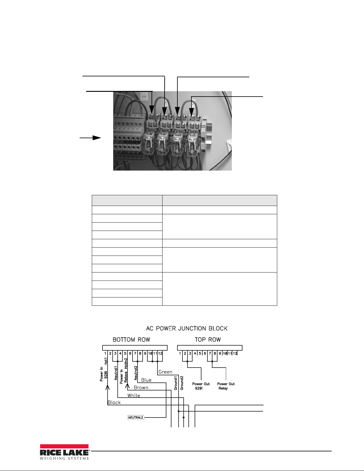
2.2 CB-2 Main Junction Block
Relay 1
Relay 2 Agg.
conveyor start
Relay 3
Relay 4 Air
Compressor
start
12 pin
connector w/
pin 1 starting at
left and shown
in greater detail
in Figure 2-3
below.
The CB-2 main junction box provides access for outside power to be brought into the enclosure using two sets of
customer supplied 110V power - one for the 920i indicator and the other for the relays/plant control.
Figure 2-2 illustrates the 12 pin connector used plus the relays.
Figure 2-2. CB-2 AC Power Junction Block
Table 2-1 lists the pin connections located on the BOTTOM ROW of the terminal strip for power to the CB-2.
Bottom Row Pin Number Function
1 Line 1, provides power to 920i
2 Neutral
3
4
5 Line 2, pr
6 Neutral
7
8
9 Ground
10
11
12
Table 2-1. CB-2 AC Power Junction Block Power Connections Into the Enclosure
ovides power to relays
Figure 2-3. AC Power 12 Pin Connector as Shown in Detail from Figure 2-2 (above)
Installation/Operation Manual - Installation 7
Page 12
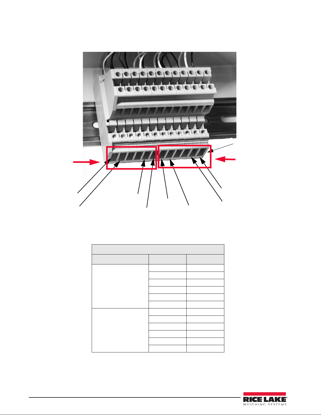
2.3 Load Cells
Pin 1
+ SIG
- SIG
+ EXC
- EXC
+ SIG
- SIG
+ EXC
- EXC
Aggregate
Side
Cement Side
The CB-2 comes pre-wired at the factory. Figure 2-4 shows the loadcell connections on the lower row.
Table 2-2 lists the load cell connections for a CB-2 automated concrete batching system that contains two load
cells.
Figure 2-4. Terminal Blocks Load Cell Connection (Metered Water)
Bottom Connector - Load Cells
Load Cell Connector Pin Number Signal
Load Cell 1
Aggregates
Load Cell 2
Cement
Table 2-2. Load Cell Connectors for Units with Two Load Cells (Metered Water)
1 - EXE
2 + EXE
3 - SEN
4 + SEN
5 - SIG
6 + SIG
7 - EXE
8 + EXE
9 - SEN
10 + SEN
11 - SIG
12 + SIG
8 Installation/Operation Manual
Page 13
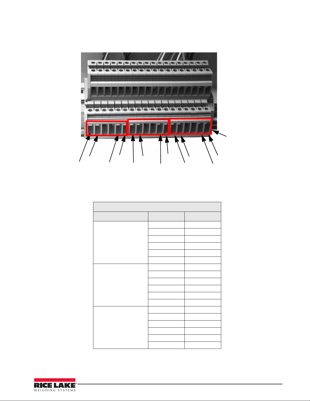
For units containing three load cells, the following table and diagram illustrate the load cell connectors used.
+SIG
- SIG
+EXC
-EXC
+SIG
-SIG
+EXC
-EXC
+SIG
-SIG
+EXC
-EXC
Pin 1
Aggregate
Side
Water Side
Cement Side
(Middle)
Figure 2-5. Terminal Blocks Load Cell Connection (Weighed Water Option)
The following table lists the load cell connections for a CB-2 automated concrete batching system that contains
three load cells.
Bottom Connector - Load Cells
Load Cell Connector Pin Number Signal
Load Cell 1
Aggregates
Load Cell 2
Cement
Load Cell 3
Water
Table 2-3. Load Cell Connectors for Units with Three Load Cells (Weighed Water)
1 - EXE
2 + EXE
3 - SEN
4 + SEN
5 - SIG
6 + SIG
7 - EXE
8 + EXE
9 - SEN
10 + SEN
11 - SIG
12 + SIG
13 - EXE
14 + EXE
15 - SEN
16 + SEN
17 - SIG
18 + SIG
Installation/Operation Manual - Installation 9
Page 14
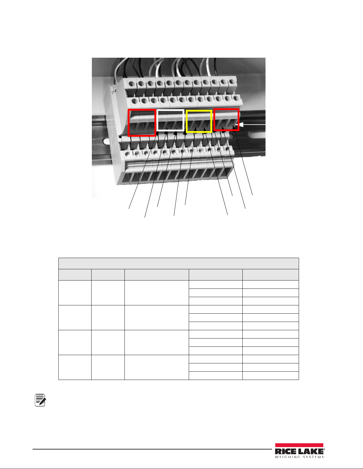
2.3.1 Serial Communications
TX
RX
GND
TX
RX
GND
TX
RX
GND
Pin 1
1
2
3
4
5
6
7
8
9
11
12
10
Note
The CB-2 supports RS-232 communications and their connections are shown in Figure 2-6, below.
Figure 2-6. Terminal Block RS-232 Connections
Serial ports are configured using the SERIAL menu which is shown in Tab le 2-4.
Top Connector - Serial Communications
Description Port # Port Connector Pin Number Signal
PC Port 1 J11
Ticket and
Report
Printer
Preprinted
Ticket Printer
iRev or
Keyboard
Port 4 J10
Port 3 J9
Port 2 _
Table 2-4. Serial Communications Connections
For CB-2 units with the weighed water option, serial connections remain the same using the same 9 pins
as is shown in Figure 2-5.
1 GND
2 RXD
3 TXD
4 GND
5 RXD
6 TXD
7 GND
8 RXD
9 TXD
10 Not Used
11 Not Used
12 Not Used
10 Installation/Operation Manual
Page 15
+
1035
+
1035
+
1035
+
1*&;0
#6;;&3
015*0/
+
o7%$
(/%
(/%
7%$
&91"/4*0/#64
(/%
343Y%
345Y%
(/%oN"065
343Y%
345Y%
N"065
343Y%
345Y%
N"065
345Y%
345Y%¦
7%$
(/%
&.&3(&/$:4501%*0
."/6"-.0%&%*0
3&.05&45"35%*0
3&.05&1"64&%*0
*/5&3'"$&
#0"3%
$0//&$5*0/
108&3
4611-:
48
+1
+
+
+
%*(*5"-*0
+
1035
015*0/$"3%
$0//&$503
015*0/$"3%
$0//&$503
015*0/$"3%-0$"5*0/4
+
#"55&3:
+
48
#005
.0%&
4-05
4-05
(/%N"065
3&.05&
4&561
48*5$)
5*$,&5"/%
3&103513*/5&3
4*/(-&
015*0/"-5*$,&5
13*/5&313*/5&3
015*0/
1$
Figure 2-7. CB-2 CPU Board, Showing Option Card Locations
Installation/Operation Manual - Installation 11
Page 16

2.4 Digital I/O
Digital inputs can be set to provide many batching functions on the CB-2. Digital inputs are active low (0 VDC),
inactive high (5 VDC).
Digital outputs are typically used to co
rather than source, switching current. Each output is a normally open collector circuit, capable of sinking 24 mA
when active. Digital outputs are wired to switch relays when the digital output is active (low, 0 VDC) with
reference to a 5 VDC supply.
Table 2-5 shows the pin assignments for connector J2 which
Table 2-5. J2 Pin Assignments (Digital I/O) on CB-2 Main Board
Digital inputs and outputs are configured using the DIG I/O menu. See Section 3.1 on page 18 for configuration
information.Table 2-6 through 2-9 lists the digital I/O channels and their pre-defined functions for the CB-2.
ntrol relays that drive other equipment. Outputs are designed to sink,
is located on the CB-2 CPU board.
J2 Pin J2 Signal Function
1 +5 VDC
2 GND
3 DIO 1 Emergency Stop
4 DIO 2 Manual Mode
5 DIO 3 Remote Start
6 DIO 4 Remote Pause
Digital I/O
Slot 3 Bit 1 Digital Output Aggregate 1 Batch 3-1 SP1
Location Ty pe Description Ter m i n a l # Setpoint
2 Aggregate 2 Batch 3-3 SP2
3 Aggregate 3 Batch 3-5 SP3
4 Aggregate 4 Batch 3-7 SP4
5 Aggregate 5 Batch - Option 3-9 SP5
6 Aggregate 6 Batch - Option 3-11 SP6
7 Aggregate 7 Batch - Otion 3-13 SP7
8 Aggregate 8 Batch - Option 3-15 SP8
9 Aggregate Discharge Open 3-17
10 Aggregate Discharge Closed 3-19
11 Aggregate Vibrator 3-21
12 Sand Bin Vibrator 3-23
13 Cement 1 Batch 3-25 SP9
14 Cement 2 Batch 3-27 SP10
15 Cement 3 Batch 3-29 SP11
16 Cement 4 Batch 3-31 SP12
17 Dust Collection 3-33
18 Alarm/Horn 3-35
19 Aggregate Conveyor Start 3-37
20 Aggregate Conveyor Stop 3-39
21 Cement Discharge Open 3-41
22 Cement Discharge Closed 3-43
23 Cement Vibrator 3-45
24 Weigh Hopper Aeration 3-47
12 Installation/Operation Manual
Table 2-6. Digital I/O Pin Assignments for Slot 3
Page 17
Digital I/O
Slot 4 Bit 1 Digital Output Reservoir Discharge 4-1 67
Location Ty pe Description Ter m i n a l # Setpoint
2 Tailwater Discharge 4-3
3 Digital Input Reservoir Gate Closed 4-5
4 Water Reservoir Empty 4-7
5 Aggregate Conveyor is Running 4-9
6 Air Pressure OK 4-11
7 Cement Gate is Closed 4-13
8 Aggregate Gate is Closed 4-15
9 Digital Output Out of Tolerance Signal 4-17
10 Load Complete 4-19
11 Reset Water Counters 4-21
12 Reset Admixtures Counters 4-23
13 Cement 1 Aeration 4-25
14 Cement 2 Aeration 4-27
15 Cement 3 Aeration 4-29
16 Cement 4 Aeration 4-31
17 Cold Water 4-33 SP17
18 Hot Water 4-35 SP18/68
19 Digital Input Not Presently Used 4-37
20 Water Meter Pulse Input 4-39
21 Digital Output Air Compressor Start 4-41
22 Air Compressor Stop 4-43
23 Lower Boot 4-45
24 Raise Boot 4-47
Table 2-7. Digital I/O Pin Assignments for Slot 4
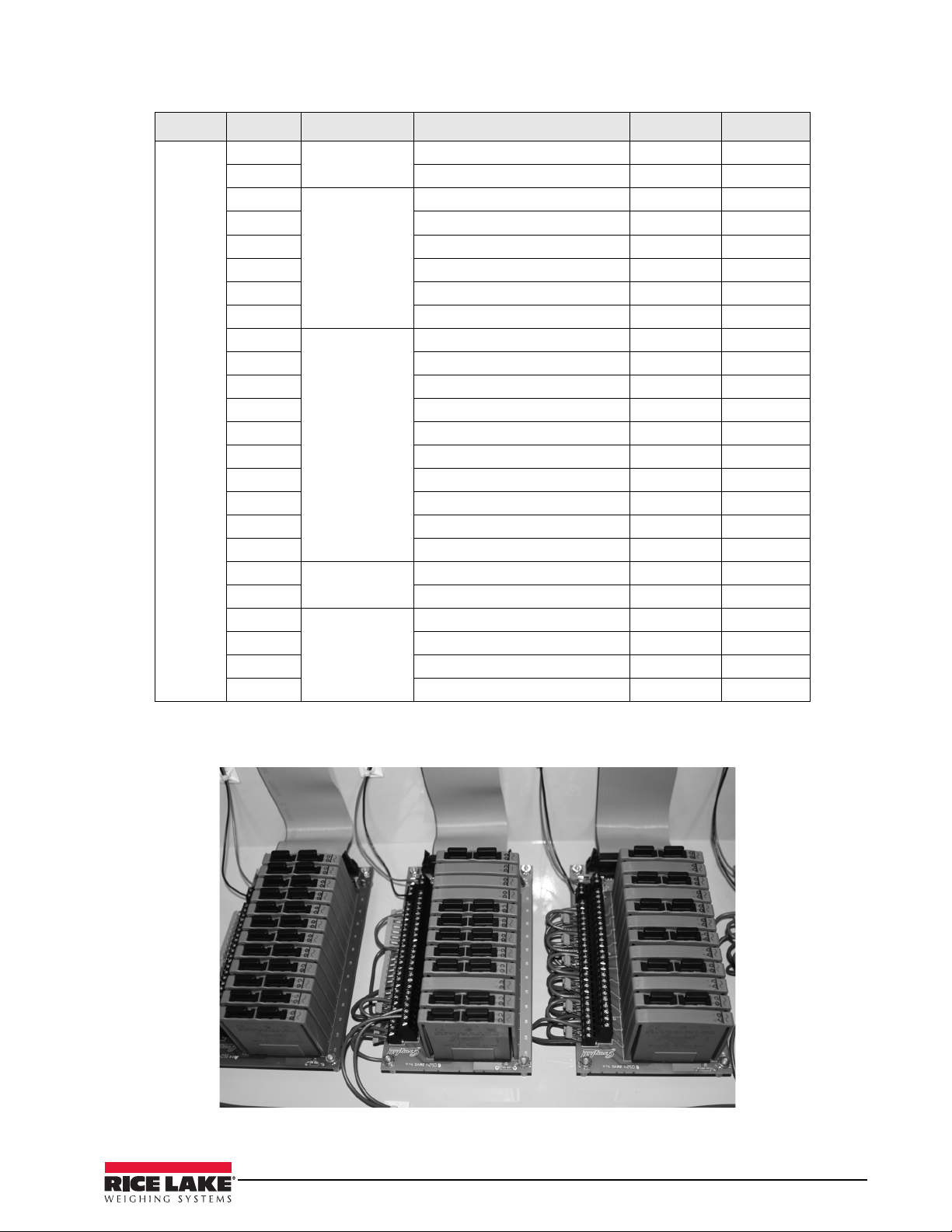
SLOT 3
SLOT 4
SLOT 5
Figure 2-7. Digital I/O Relay Racks for the CB-2 Automated Concrete Batching System
Installation/Operation Manual - Installation 13
Page 18

Digital I/O
Slot 5 Bit 1 Digital Output Admixture 1 Fill/Feed 5-1 SP19
Location Ty pe Description Ter m i n a l # Setpoint
2 Admixture 1 Discharge 5-3
3 Digital Input Admixture 1 Bottle Empty Light 5-5
4 Admixture 1 Pulse Light/Counter 5-7
5 Digital Output Admixture 2 Fill/Feed 5-9 SP20
6 Admixture 2 Discharge 5-11
7 Digital Input Admixture 2 Bottle Empty Light 5-13
8 Admixture 2 Pulse Light/Counter 5-15
9 Digital Output Admixture 3 Fill/Feed 5-17 SP21
10 Admixture 3 Discharge 5-19
11 Digital Input Admixture 3 Bottle Empty Light 5-21
12 Admixture 3 Pulse Light/Counter 5-23
13 Digital Output Admixture 4 Fill/Feed 5-25 SP22
14 Admixture 4 Discharge 5-27
15 Digital Input Admixture 4 Bottle Empty Light 5-29
16 Admixture 4 Pulse Light/Counter 5-31
17 Digital Output Admixture 5 Fill/Feed 5-33 SP23
18 Admixture 5 Discharge 5-35
19 Digital Input Admixture 5 Bottle Empty Light 5-37
20 Admixture 5 Pulse Light/Counter 5-39
21 Digital Output Admixture 6 Fill/Feed 5-41 SP24
22 Admixture 6 Discharge 5-43
23 Digital Input Admixture 6 Bottle Empty Light 5-45
24 Admixture 6 Pulse Light/Counter 5-47
Table 2-8. Digital I/O Pin Assignments for Slot 5
14 Installation/Operation Manual
Page 19

Note
WARNING
Digital I/O
Slot 8 Bit 1 Digital Output Mixer Start 8-1
Location Ty pe Description Ter m i n a l # Setpoint
2 Mixer Stop 8-3
3 Mixer Discharge Gate Open 8-5
4 Mixer Discharge Gate Closed 8-7
5 Digital Input Mixer Gate is Closed 8-9
6 Truck/Mixer in Position 8-11
7 Digital Output Watchdog Pat 8-13
8 Not Used 8-15
9 Cement 5 8-17 13/59
10 Cement 6 8-19 14/60
11 Cement 7 8-21 15/61
12 Cement 8 8-23 16/62
13 Aux Output #1 8-25 51
14 Aux Output #2 8-27 52
15 Aux Output #3 8-29 53
16 Aux Output #4 8-31 54
17 Aux Output #5 8-33 55
18 Aux Output #6 8-35 56
19 Aux Output #7 8-37 57
20 Aux Output #8 8-39 58
21 Aux Output #9 8-41
22 Aux Output #10 8-43
23 Aux Output #11 8-45
24 Aux Output #12 8-47
Table 2-9. Digital I/O Pin Assignments for Slot 6
2.5 Battery Replacement
The 3V, coin type lithium battery (PN 69290) on the
CPU board maintains the real-time clock and protects
data stored in the system RAM when the indicator is
not connected to AC power.
Data protected by the CPU board
time and date, truck and tare memory, onboard
database information, and setpoint configuration.
iRev to store a copy of the indicator configuration
Use
on a PC before attempting battery replacement. If any
data is lost, the indicator configuration can be restored
from the PC.
Risk of explosion if battery is replaced with incorrect type. Dispose of batteries per manufacturer
instruction.
battery includes
Memory option card data is also protected
by a lithium battery. All database
inf
ormation stored on a memory card is lost
if the memory card battery fails.
Watch for the low battery warning on the LCD display
and periodically check the battery voltage on both the
CPU board and on any installed memory option cards.
Batteries should be replaced when the indicator low
battery warning comes on, or when battery voltage
falls to 2.2 VDC. Life expectancy of the battery is ten
years.
See Figure 2-7 on page 11 for CPU board battery
location and orientation (positive side up).
Installation/Operation Manual - Installation 15
Page 20

2.6 Replacement Parts
Table 2-3 lists replacement parts for the CB-2 automated concrete batching system.
PN Description
88792 Power supply, 12V (1)
67609 Memory module 1MB (1)
67612 Board assembly, CPU for 920i (1)
93536 Totalizing counters (7)
42467 Relays, 120V models
96008 Relays, 220V models
89198 CB-2 switch board assembly (4)
93540 CB-2 switch board assembly (2)
67608 Expansion board, digital I/O (1)
71462 Fuse, 3.15amp
52315 Relay mounting board (1)
67614 LCD, fluorescent display (1)
67869 920i interface board (1)
52318 Relay, input module, 12V
52319 Relay, Input module, 220V model
52316 Relay, output module, 12V
52317 Relay, output module, 220V model
89199 Breakout board assembly
69781 iRev CD
67612 920i Main Board for the CB-2
Table 2-11. Part Numbers for 920i Option Cards
2.6.1 Option Cards
Table 2-11 lists the available option 920i option cards that are used in the CB-2 automated concrete batching
system. Any of the listed option cards can be installed in Slot 1 or Slot 2 of the CPU board or in any available slot
of an attached expansion board.
Option Card Rice Lake Part Number
Single Channel A/D Card 68532
Dual Channel A/D Card 67611
1 MB NV RAM Memory Expansion Card 67609
Table 2-11. Part Numbers for 920i Option Cards
16 Installation/Operation Manual
Page 21

2.7 Installing an Optional PS-2 Keyboard
To increase the speed and ease of entering alpha-numeric data, a standard PS/2 keyboard can be connected. Use
the following steps to install a PS/2 keyboard.
1. Place the 920i into Setup Mode by pressing the setup switch. See Section 1.1 (setup mode) for finding
and pressing the setup switch. This may involve breaking an inspectors lead seal.
2. When the 920i enters into Setup Mode, Scales is selected. Press the right arrow key on the keypad, so
Serial is selected.
3. Press the down arrow key once. Port 1 is selected.
4. Press the right arrow key once to select Port 2.
5. Press the down arrow key one. CMD will be selected.
6. Press the right arrow key once to select KEYBRD.
7. Press the Up arrow key twice. SERIAL should be selected and there should be a Save and Exit softkey in
the lower right-hand side of the display.
8. Press the Save and Exit softkey.
9. Power down the CB-2 with the key switch.
10. Bring the end of the PS/2 keyboard cable into the CB-2 through one of the cord grips on the back of the
enclosure. Plug in the PS/2 keyboard into the PS/2 connector (located between the display contrast
potentiometer and the DB-9 serial port) about 2” away from the setup switch. Your CB-2 may be
equipped with an optional keyboard connector extension. If this is the case, there will be a cable running
out of the back of the CB-2 enclosure with a female PS/2 connector on the end of it.
11. Power up the CB-2 with the key switch.
12. Test the keyboard. F1 to F5 on the keyboard should map to the softkeys from left to right, respectively.
Installation/Operation Manual - Installation 17
Page 22

3.0 Configuration of Scale Parameters
Note
The CB-2 is designed as a universal controller for all types of automated concrete production. There are many
settings and features that are only used by special applications. The factory default settings assume a two-scale
transit mix application and most of the default values will not need to be changed for this type of application. In
addition, system software has been pre-loaded along with a default database.
However, for the CB-2 to batch accurately, certain critical paramet
tuned (see tune plant section). As part of the default configuration, a minimum number of materials, physical
locations, and mix designs have been added. The mapping of the actual physical plant controls to the I/O points
in the software is also setup in the initial configuration.
To set up a standard configuration the
920i indicator, the indicator must be placed in setup mode. The setup
switch is accessed by removing the large fillister head screw on the back of the enclosure. Switch position is
changed by inserting a screwdriver into the access hole and pressing the switch.
When the indicator is placed in setup mode, a series of menus is shown
the words
Scale Configuration. The SCALES menu is highlighted as the first used to configure the indicator.
Detailed descriptions of these menus are provided in Section 3.2.
When configuration is complete, press the
Exit or Save and Exit softkey to exit setup mode, then replace the setup
switch access screw.
•The
Exit softkey exits setup mode without saving parameter changes to NV RAM. Changes made to the
configuration remain in the system until indicator power is cycled.
Save and Exit writes all parameter changes to NV RAM before returning to normal mode.
•
3.1 Configuration Methods
The 920i indicator can be configured by using the front panel keys to navigate through a series of configuration
menus or by sending commands or configuration data to an indicator serial port. Configuration using the menus
is described in Section 3.1.2.
Configuration using the serial port can be accomplished using e
configuration utility.
Some configuration parameters, such as those used to configure the 920i display and widgets, cannot
be accessed through the configuration menus. iRev provides the most complete and efficient
configuration interface for the 920i.
ers must be determined and the plant must be
across the top of the display, along with
ither the serial command set described in the iRev
3.1.1 iRev Configuration
The iRev configuration utility provides the preferred method for configuring the 920i indicator. iRev runs on a
personal computer to set configuration parameters for the indicator. When
configuration data is downloaded to the
iRev supports both uploading and downloading of indicator configuration data. This capability allows
920i indicator.
iRev configuration is complete,
configuration data to be retrieved from one indicator, edited, then downloaded to another indicator with an
identical hardware configuration.
18 Installation/Operation Manual
Page 23
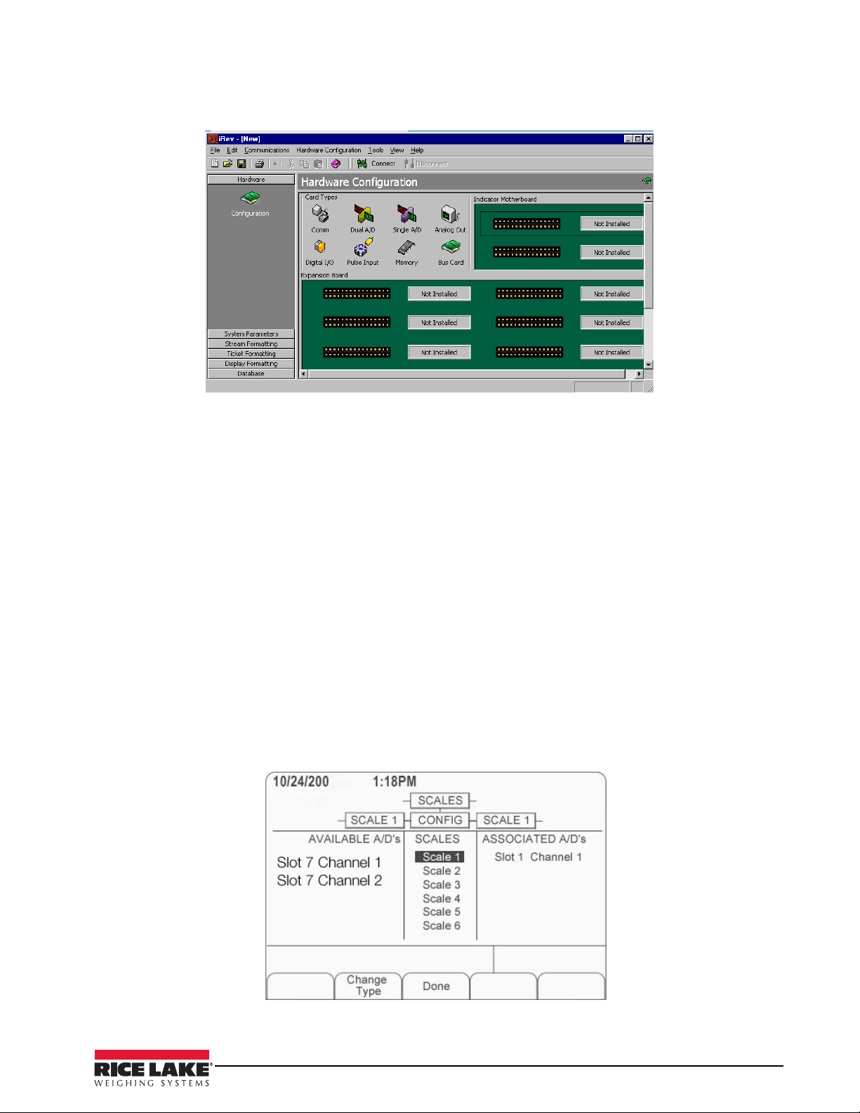
Figure 3-1. iRev Hardware Configuration Display
To use iRev, do the following:
1. Install
iRev on an IBM-compatible personal computer. See XX for detailed hardware and software
requirements.
2. With both indicator and PC powered off, connect the PC
serial port to the RS-232 pins on the indicator
serial port.
3. Power up the PC and the indicator. Use the setup sw
4. Start the
iRev provides online help for each of its configuration displays. Parameter descriptions provided in this manual for
iRev program.
front panel configuration can also be used when configuring the indicator using
itch to place the indicator in setup mode.
iRev: The interface is different, but
the parameters set are the same.
See the 9
920i.
20i Installation and Operation Manual, PN 67887 for more information about using iRev to configure the
3.1.2 Front Panel Configuration
Use the CONFIG submenu under the SCALES menu to configure A/D scales. For example, in an indicator with
a single-channel A/D card installed in Slot 1, the Scale Configuration display will show the A/D listed (
Channel 1
softkey,
AVAILABLE A/D’s column, the center softkey changes to Done, as shown in Figure 3-2. Press Done to exit the Scale
) under the AVAILABLE A/D’s column. Use the left navigation key to select the A/D, then press the center
Add. The A/D is then moved to the Associated A/D’s column. If no other A/D’s are listed in the
Slot 1
Configuration display.
Figure 3-2. Scale Configuration Display
Installation/Operation Manual - Configuration of Scale Parameters 19
Page 24
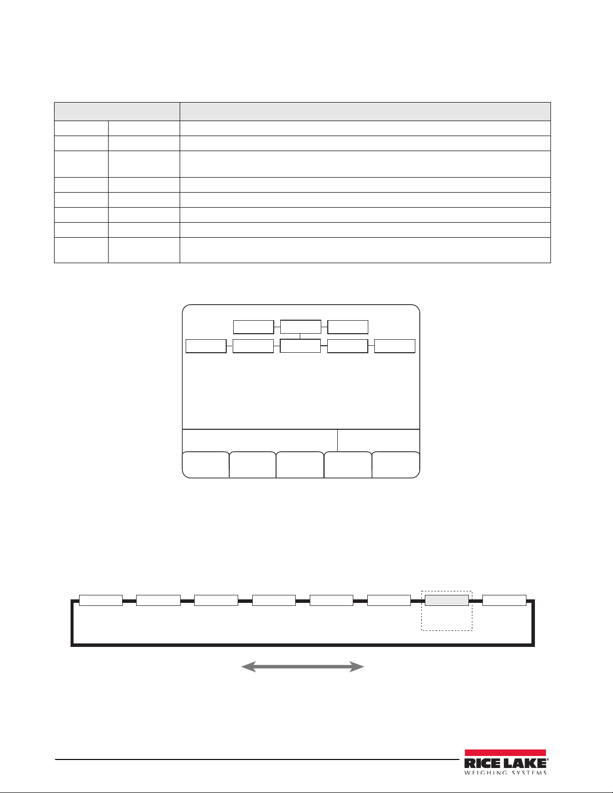
The 920i indicator can be configured using a series of menus accessed through the indicator front panel when the
05/30/2013
08:13AM
Exit
Scale 1 Configuration
Save
and Exit
SERIAL
SCALES
VERS
SCALE 2
SCALE 1
CONFIG SCALE 2 CONFIG
4$"-&4 4&3*"- '&"563& 1'03.5 4&5154 %*(*0 "-(065 7&34
4IPXOPOMZJG
"OBMPH0VUQVU
DBSEJTJOTUBMMFE
indicator is in setup mode. Table 3-1 summarizes the functions of each of the main menus.
Menu Menu Function
SCALES Configuration Configure and calibrate scales.
SERIAL Serial Configure communications ports.
FEATURE Feature Set date and time formats,
initial consecutive number value, define softkeys and setpoint prompts.
PFORMT Print Format Set print format used for header, g
SETPTS Setpoints Configure setpoints and batching mode.
DIG I/O Digital I/O Assign digital input/output functions.
ALGOUT Analog Output Configure analog output module. Used only if an
VERSION Ver sion Display installed software version number. The Re
be used to restore all configuration parameters to their default values.
Table 3-1. 920i Menu Summary
truck mode, passwords, keyboard locks, regulatory mode, and
ross, net, truck in/out, setpoint, and auxiliary ticket formats.
alog output option is installed.
set Config softkey on the Version menu can
Figure 3-3. Scale 1 Configuration
3.2 Menu Structures and Parameter Descriptions
The following sections provide graphic representations of the 920i menu structures and tables describing the
menu parameters. Default values are shown in bold type; numeric ranges and string values are shown in italic
type. Parameters shown surrounded by a dotted-line box only appear under the special circumstances explained
under each box.
Figure 3-4. Configuration Menu Flow
20 Installation/Operation Manual
Page 25
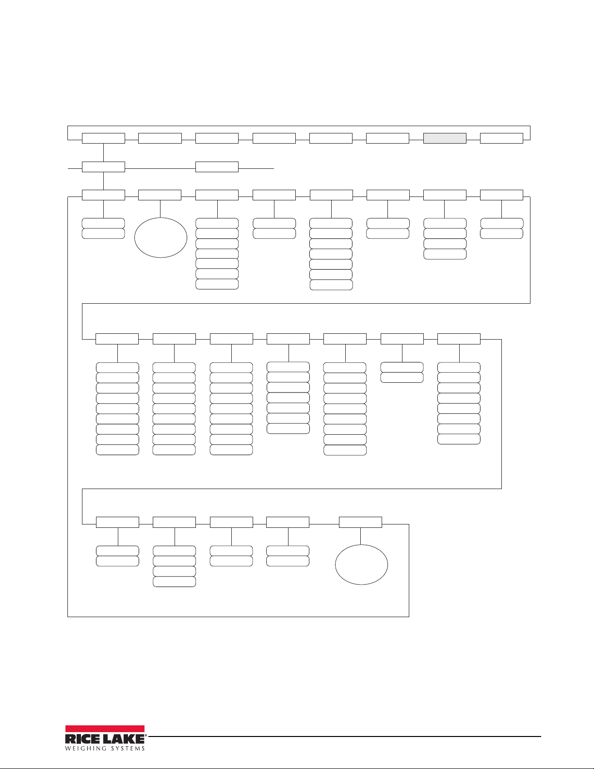
3.2.1 SCALES Menu
4$"-&4 4&3*"- '&"563& 1'03.5 4&5154 %*(*0 "-(065 7&34
4$"-&Y
(3"%4
;3"/(& .05#"/%
073-0"%
445*.&
%*('-5 %*('-5
OVNCFS
;53,#/%
0''
%
%
%
%
%
%
%
%
%
'4
'4%
'4%
'4
OVNCFS
%'4&/4 3"553"1
%'5)3)
4.13"5
18361.% 5"3&'/
065
065
065
065
065
065
065
%
%
%
%
%
%
%
/0/&
%
0''
0/
);
);
);
);
);
);
);
);
(0
%&-":
#05)
1#5"3&
/05"3&
,&:&%
4FF
'03."5
4VCNFOV
0''
%
%
%
%*('-5
$0/'*(
"$$6.
$"-*#3
0''
0/
7*4*#-&
0/
0''
'03."5
4FF
$"-*#3
4VCNFOV
8.55)3)
OVNCFS
The SCALES menu is shown in Figure 3-5. Parameters shown in each diagram are described in the table
following that diagram.
Figure 3-5. SCALES Menu
Please refer to PN 67887, 920i Installation Manual, for additional information on scale parameters and
their descriptions.
Installation/Operation Manual - Configuration of Scale Parameters 21
Page 26
4.0 Configuration of User Parameters
05/30/2013 08:13AM
Admin Menu
CB-2 2 Scale
Prepare
Load
Utilities
SCALE 1
EZ-Change
Criticals
AGG
CEM
Scale
Scale
#1
#2
lb Gross
lb Gross
00
0
1SFQBSF
-PBE
6UJMJUJFT
"ENJO
.FOV
&;$IBOHF
$SJUJDBMT
*OUFSWBMT
5JNFST
4FSJBM1PSUT%BUBCBTFT
"QQMJDBUJPO
1BSBNFUFST
4JNVMBUJPO
.PEF4FUVQ
$MPDL 1BTTXPSE
#BUDIJOH
1SFGFSFODFT
#BUDIJOH-JNJUT
1$1PSU
4FF"EEJUJPOBM
4VC1BSBNFUFST
BOEEFTDSJQUJPOT
MPDBUFEJO
5BCMF
8BUFS4ZTUFN
"ENJY4ZTUFN
.JYJOH4ZTUFN
#BUDIJOH-JNJUT
5JDLFUT3FQPSUT
4FUVQ
*%T
.BUFSJBMT
#BUDIJOH-JNJUT
4DBMFT
.JYFT
-PBET
-PDBUJPOT
0SEFST
$VTUPNFST
5SVDLT
4FF"EEJUJPOBM
4VC1BSBNFUFST
BOEEFTDSJQUJPOT
MPDBUFE
JO5BCMF
.BY5JNF
#FUXFFO1VMTFT
#BUDIJOH-JNJUT
"HH$POWFZPS
3VOPVU5JNF
1SJOU-JOF%FMBZ
#FFQ%VSBUJPO
4UBSU$POWFZPS
8BSOJOH5JNF
%JTQMBZ5JNF
%BUB&OUSZ
5JNFPVU
$POmHVSBUJPO
&YJU5JNFPVU
1BTTXPSE
5JNFPVU
#BUDIJOH-JNJUT
%FCVH1SPDFTT
1PSU
5JDLFU1SJOUFS
1PSU
%FCVH-PHJD
1PSU
3FQPSU1SJOUFS
1PSU
#BUDIJOH-JNJUT
*HOPSF"MM*OQVUT
*HOPSF.JYFS(BUF
-JNJU4XJUDI
8BJUGPS5PM
"DDFQU
%JTBCMF0VUQVUT
"VUP4FRVFODF
%FMBZ
+PH5JNF
$PSSFDUJPO
4DBMF
3BNQ6Q
4DBMF
3BNQ6Q
4DBMF
3BNQ6Q
4DBMF
3BNQ6Q
4DBMF
3BNQ%PXO
4DBMF
3BNQ%PXO
4DBMF
3BNQ%PXO
4DBMF
3BNQ%PXO
5JNF
#BUDIJOH-JNJUT
%BUF
%BUF'PSNBU
5JNF'PSNBU
,FZJO/FX
1BTTXPSE
#BUDIJOH-JNJUT
3FLFZ/FX1BTT
XPSEUP7FSJGZ
/FX1BTTXPSE
"DDFQUFE
,EVEL0ARAMETERS
,EVEL0ARAMETERS
,EVEL0ARAMETERS
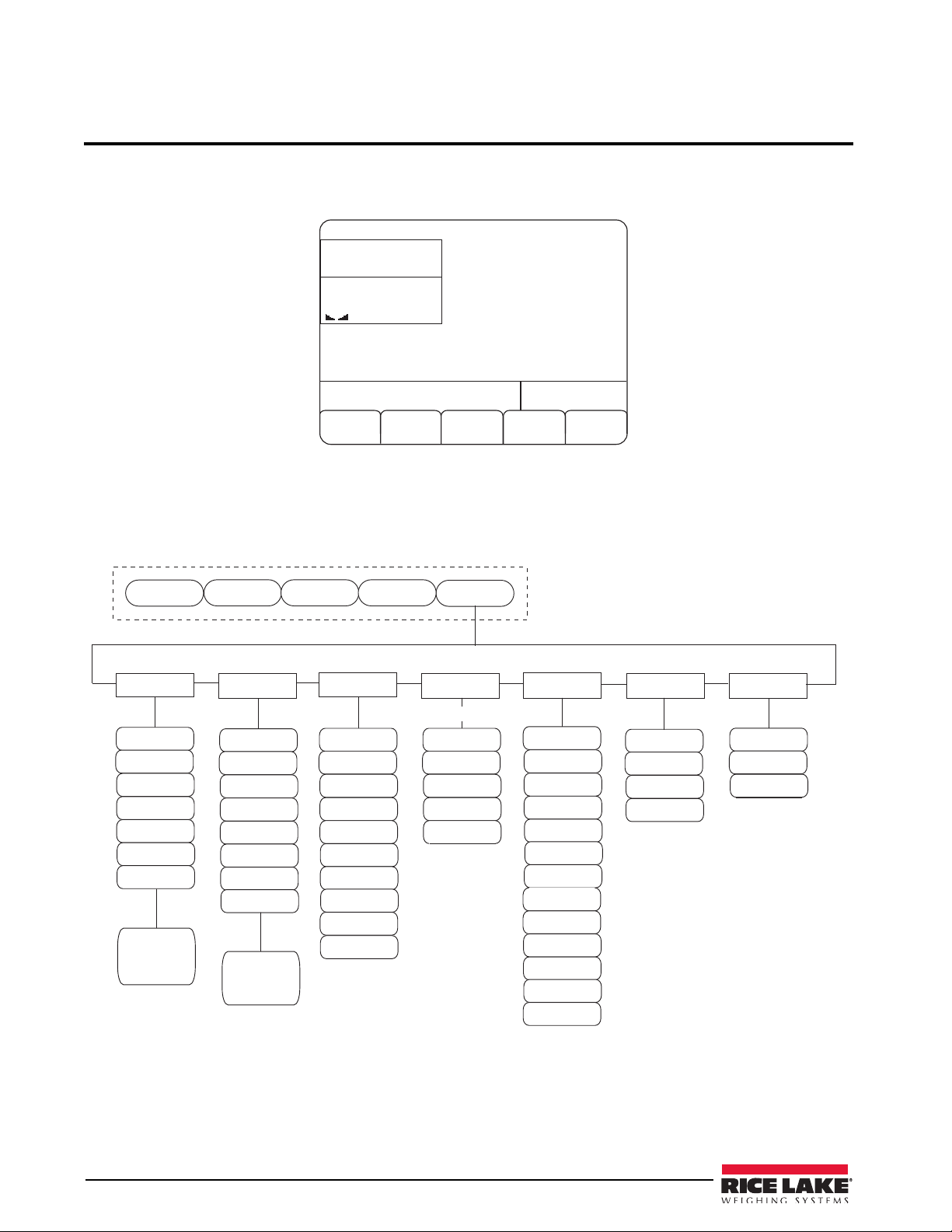
The CB-2 has many parameters that must be configured in order for the unit to batch properly. Use the
configuration parameters mode to set values for parameters controlling system operation. Press the
softkey to access those configuration parameters which are listed in Figure 4-2.
Figure 4-1. Admin Menu Softkey Location
All of the Admin Menu parameters are listed below in the following flow chart to better help illustrate all of the
different parameter levels that must be set to ensure proper operation. To access each sub-parameter use the
down arrows on the 920i to scroll up or down through the various menu choices.
Admin Menu
up or
22 Installation/Operation Manual
Figure 4-2. Admin Menu Flowchart
Page 27
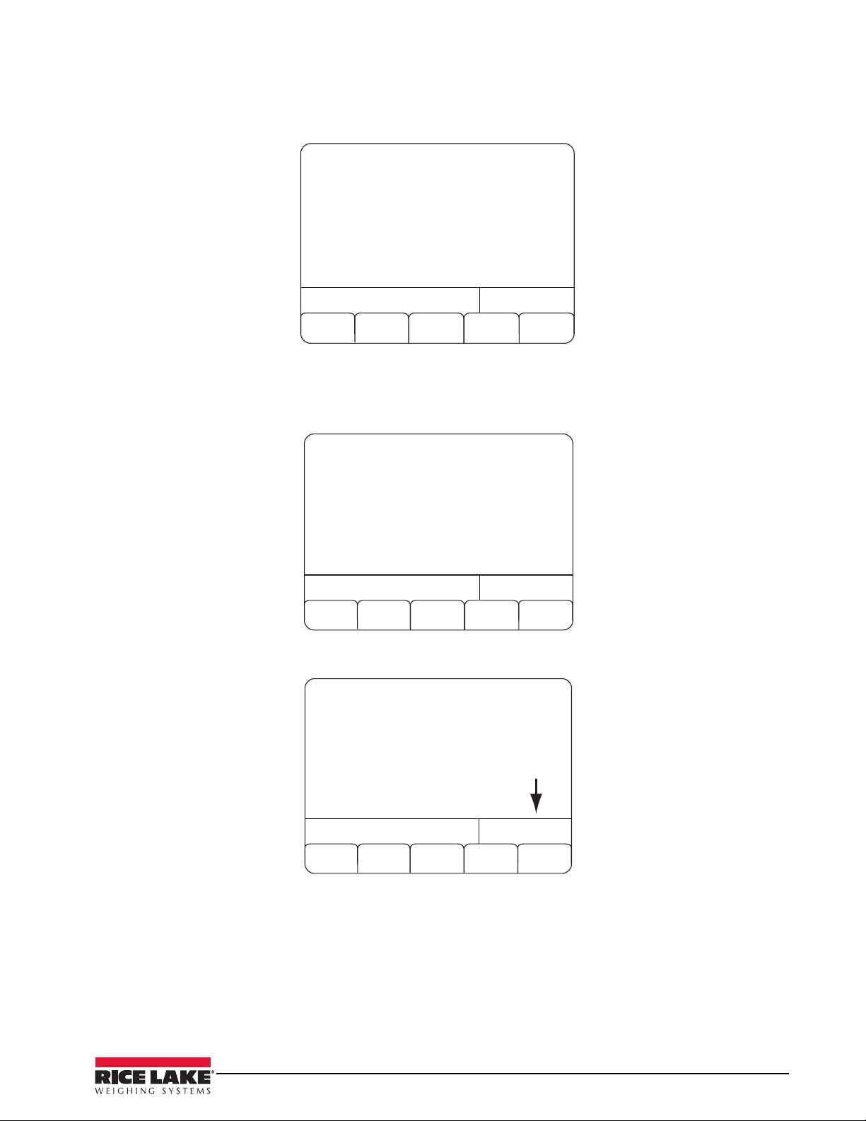
4.1 Application Parameters
05/30/2013 08:13AM
Exit
Application Parameters
SCALE 1
Application Parameters : ==>
Databases : ==>
Intervals and Timers : ==>
Serial Ports : ==>
Simulation Mode Setup : ==>
Clock : ==>
Password : ==>
Select Category
05/30/2013
08:13AM
Exit
Batching Preferences
SCALE 1
Batching Preferences : ==>
Batching Limits : ==>
Water System : ==>
Admix System : ==>
Mixing System : ==>
Tickets/Reports Setup : ==>
IDS : ==>
Application Parameters
05/30/2013
08:13AM
Exit
Order Based Loading
SCALE 1
Order Based Loading : Yes
Metric (S.I.) System : No
State Regulatory Mode : Standard
Prompt for Truck ID : Yes
NET Mode Batching : No
Split Batching Allowed : Yes
Split Batch Even 1/4 : Yes
Batching Preferences
‘Discharge’ Keypress Required : FirstBatch
Aggregate Conveyor Control : Manual
Maintain Conveyor Power : No
No
Yes
The Application Parameter menu category is the first item displayed under the Admin Menu softkey.
Figure 4-3. Application Parameters Screen
If there is a right arrow displayed on the 920i screen, that means that there are more menu choices to choose
from. Press the
Again, press the
right arrow key on the 920i to access additional menu choices. A list of sub menus are displayed.
right arrow to access the additional sub-parameters as shown below.
Figure 4-4.
Batching Preferences
Figure 4-5. Order Based Loading
Each menu item is set up similarly by navigating through the various menu structures and entering parameter
values for each.
The following tables describe the sub-parameters for
each parameter listed.
Installation/Operation Manual - Configuration of User Parameters 23
Page 28

Application Parameters
ADMIN Menu
Parameter Choices Description
Level 2 Sub-menu
APPLICATION PARAMETERS
Level 3 Sub-menu
Batching Preferences
Level 4 Sub-menu ADMIN MENU/APPLICATION PARAMETERS/BATCHING PREFERENCES
Bolded items indicate the softkey default settings
Order Based Loading Load Only
Order Only
Mixed
Keyed Order ID
Metric (S.I.) System No
State Regulatory Mode Standard
Mix Design Weights
No
Yes
Yes
MnDot
CAL TRAN
NYSDOT
Other
SSD
OD
Select the Load Only softkey if all loads will be entered individually. Order Only
if all loads will be done through orders, and Mixed if some will be orders and
some individual loads.
Select Yes if you wish to enter your own order IDs.
Select Yes if operating using metric measurements.
Selects the desired state regulatory mode to operate in.
(Only Standard and MnDOT are currently supported)
See Truck Formatting information in Section xx on page dd for more
information on MnDot regulatory mode.
Indicate whether aggregate weights in the mix designs will be in Saturated
Surface Dry or Oven Dry weights.
Batching Mode
Split Batching Allowed No
Split Batch Even No
Continuous Batching
Tar ge t
Design
Yes
Yes
No
Yes
Count
Partial
(Note: MnDOT installations are always OD - oven dry.)
Target mode batching (default) will adjust the amount of each ingredient on a
scale based on the amount of the ones previously dispensed to come as
close as possible to the target number of yards/cubic meters.
Design mode batching will attempt to batch the design amount of a material
to come as close as possible to the mix design material proportions. Design
mode batching is currently unsupported.
Select Yes if trucks may be loaded that exceed the plant capacity. Trucks with
up to five times plant capacity may be loaded.
Select Yes to split the batches equally. Otherwise, all but the final batch will
be at plant capacity.
In an order based system, selecting Yes will cause the multiple loads of a
multi-load order to be run automatically one after the other until the order is
filled.
In a load based system, the same load will be run continuously until the Last
Batch softkey is pressed.
Count will prompt for a number of batches to run continuously.
Partial will prompt for a number of single batch units to run. The number can
include partial amounts and no batch will exceed a single unit. For instance, if
a mix design is specified that generates one yard and the operator keys in
1.6, the CB-2 will generate 1.6 yards of product in two 0.8 yard batches.
Likewise, if a mix design is specified that would generate two yards of material
and the operator enters 2.5 at the prompt, the CB-2 will determine that three
batches are required and generate five yards of product in three 1 2/3 yard
batches.
24 Installation/Operation Manual
Table 4-1. Application Parameters Sub-menu List
Page 29

ADMIN Menu
Parameter Choices Description
Prompt for Truck ID No
Yes
‘Discharge’ Keypress Required Never
First Batch
Always
Aggregate Conveyor Control Manual
Auto
Maintain Conveyor Power No
Yes
Boot Control Manual
Auto
Pipe Line/Preweigh Next Batch No
Yes
Weigh-up Dust Collecting No
Yes
Wait for Tol. Accept No
Yes
Scale Inspect Mode No
Yes
ESTOP is Fatal No
Yes
Air Pressure Sensor No
Yes
Auto Correct Preact Weights No
Yes
Auto Correct Jog Weights No
Yes
Jog Correction 50 % of difference used to adjust.
Auto Correct Burst Times No
Yes
Zero Tolerance Override Required No
Yes
Auto Advance Jog Tuning No
Yes
Prompt for a 1 to 6 character truck ID when preparing to batch a load.
Select to require a softkey be pressed before starting the discharge cycle.
Select First Batch to require the Discharge keypress only on the first batch
while split batching.
(Note that this does not apply to water added during weigh-up.)
Manual control of the aggregate conveyor indicates that the operator will
manually start the conveyor.
Auto indicates that the CB-2 will start and stop the conveyor. Note that if Auto
is selected it is critical that an audible alarm and light be wired to the system
alarm output to warn before the conveyor is started.
Yes indicates that the Aggregate Conveyor Start output must remain on to
keep the conveyor operating. No indicates the output is to be pulsed to latch
the conveyor on.
Manual control is selected if either the discharge boot is manually controlled
or if there is none.
In auto mode, the Lower Boot output is pulsed on for two seconds at the
beginning of the discharge cycle, and the Raise Boot output is pulsed on for
two seconds when the discharge is completed.
With split batching, pipe lining allows a scale to be used to weigh ingredients
for the next batch for a multi-batch load as soon as the discharge for the
scale is complete for the current batch
If Yes, the Dust Collection output will be set on while cement is being
dispensed into the cement hopper scale. (Dust collection is not supported for
a loss in weight cement scale.)
Set to No to bypass any operator intevention required to bypass tolerance
exceptions.
In scale inspection mode, the system will pause when the tolerance check is
done if the scale is in tolerance to allow the inspector to force an out of
tolerance condition
If the Yes softkey is selected, pressing the ESTOP button will automatically
cancel the current batch.
Yes indicates that the Air Pressure OK digital input must be on before the
weigh-up or discharge cycle may begin.
Yes will automatically correct the preact weight levels based on actual results.
Yes will automatically correct the jog weight levels based on actual results.
Yes will automatically correct inching gate burst times based on actual results.
Yes will require a softkey press to continue if the scale is outside the zero
tolerance band at the start of weigh-up.
No indicates that no action will be required if a scale is outside the zero
tolerance band at the start of weigh-up.
No zero tolerance checking is done on loss in weight scales.
This feature is currently unsupported.
.
.
Table 4-1. Application Parameters Sub-menu List
Installation/Operation Manual - Configuration of User Parameters 25
Page 30

ADMIN Menu
Parameter Choices Description
Start Allowed in ‘Manual’ mode No
Yes
Jog and Correct Last Batch Only No
Yes
Batcher Air After Weigh-up No
Yes
Delete Load Rec After Load No
Yes
Batching Limits
Level 4 Sub-menu ADMIN MENU/APPLICATION PARAMETERS/BATCHING LIMITS
Maximum Plant Capacity 10.0 Maximum plant capacity in yard/cubic meters.
Minimum Plant Capacity 0.25 Smallest allowable quantity. Must not be greater than 1/2 of the maximum
To t a l Ya r d s ( D a i ly ) These four values are accumulators maintained by the CB-2. The time frames
Total Yards (Weekly)
Total Yards(Monthly)
Total Yards (Yearly)
Water System
Level 4 Sub-menu ADMIN MENU/APPLICATION PARAMETERS/WATER SYSTEM
Weighed Water No
Yes
Water Reservoir No
Yes
Start Water with Weigh-up No
Yes
Water to Truck/Mixer First No
Yes
Start Water With Discharge
Manual
Cement Discharge
Aggregate Discharge
Skiphoist Discharge
Weighup
Material 1
Material n
Suspend Water During Cement No
Yes
Percent Tailwater 20 Percent of total water to be added after all other materials have been added
Minimum Tailwater Amount 20 gal/160 lb Minimum amount of tailwater.
Truck Washout Amount 300 gal/2500 lb Amount of water to be used to do a truck washout (code 9274).
Select Yes to allow a batch to be started while in Manual mode.
If Yes is selected, jogging will only be done on the final batch of a split batch
load.
Select Yes to have the cement weigh hopper aeration start just after the last
ingredient is weighed on the cement scale.
If no is selected the load record will be retained after the load has been
processed.
plant capacity.
(daily, weekly, etc) are arbitrary. Each value contains the amount batched
since the last time it was set to zero.
No for metered water, Yes for weighed. The default for a two scale system is
No and for a three scale system is Yes.
Yes if water is to be metered into a reservoir, No if water is weighed or directly
metered into the truck or mixer.
Yes if water can be dispensed into the truck or mixer while the other materials
are being weighed.
Yes to discharge all head water (excluding tail water) into truck/mixer before
aggregates and cement are added.
Discharge will automatically start the front water discharge at the beginning of
the discharge cycle.
Manual will display a Start Water softkey during weigh-up to allow the
operator to begin dispensing water before the other materials have been
weighed. (If the water discharge has not begun before the discharge cycle
begins, the water is added at that point.)
Cement Discharge will start the front water discharge when the cement
discharge begins.
Aggregate Discharge will start the front water discharge when the aggregate
discharge begins.
Skiphoist Discharge will start the front water discharge when the aggregate
skiphoist discharge begins.
Weighup will start the water discharge while the other materials are being
weighed.
Select a material to start adding the water when the weigh up of that material
begins.
Yes will suspend water and admixture discharge while cement is being
discharged.
to the truck or mixer.
26 Installation/Operation Manual
Table 4-1. Application Parameters Sub-menu List
Page 31

ADMIN Menu
Parameter Choices Description
Water Adjust per Batch No
Yes
Admix System
Level 4 Sub-menu ADMIN MENU/APPLICATION PARAMETERS/ADMIX SYSTEM
Suspend Admixture Addition No
Yes
Single Empty Signal No
Yes
Mixing System
Level 4 Sub-menu ADMIN MENU/APPLICATION PARAMETERS/MIXING SYSTEM
Enable Mixer Controls No
Yes
Auto Start/Stop Mixer No
Yes
Mixer Start is Latched No
Yes
Auto Discharge Mixer No
Yes
Power Discharge Gate to Close No
Yes
Discharge Gate Close Time 3.0 Time in seconds for the mixer discharge gate to open/close. If Power
Mixer Discharge Time 8.0 Maximum time in seconds for the mixer to discharge.
Gate Closed Limit Switch No
Yes
Gate Open Limit Switch No
Yes
Ticket/Reports Setup
Level 4 Sub-menu ADMIN MENU/APPLICATION PARAMETERS/TICKETS & REPORTS SETUP
Print Custom Batch Ticket No
Yes
Print Ticket Number No
Yes
# Line Feeds Number of initial lines to space to reach correct starting location.
DOT Header “Certificate of Compliance” This string will be printed at the head of any ticket printed for an order that has
Source Length 6 Maximum printable material source length.
Yes if the water adjustment amounts are to be per batch, No if they are to be
per yard/cubic meter.
Set this to Yes to inhibit the adding of all admixtures without changing the mix
designs
.
Yes if Admixture 1 Bottle Empty on indicates all bottles are empty.
Set to Yes if a mixer is part of your system and you wish to have the CB-2
control it.
If Yes, the CB-2 will control the running of the mixer.
If Yes, the CB-2 will pulse the Mixer Start output on for two seconds to start
the mixer and pulse the Mixer Stop output to stop the mixer.
Otherwise, the Mixer Start output is set on and held on to run the mixer.
If Yes the CB-2 will control the discharge of the mixer.
If Yes, CB-2 will set the Mixer Gate Close output on to close the mixer
discharge gate.
Discharge Gate to Close was set to Yes, this is the amount of time the Mixer
Gate Close output will be held on. If Gate Open Limit Switch is set to No and
Power Discharge Gate to Close to Yes, this is the amount the Mixer Gate
Open output will remain on to open the gate.
If Yes, CB-2 will use the Mixer Gate is Closed input to recognize that the gate
is closed.
If Yes, CB-2 will use the Mixer Gate is Open input to recognize that the gate is
open.
Print Custom Batch Ticket (requires special software)
Select Yes to print the batch ticket number on the batch ticket.
it’s DOT parameter defined as other than None.
Table 4-1. Application Parameters Sub-menu List
Installation/Operation Manual - Configuration of User Parameters 27
Page 32

ADMIN Menu
Parameter Choices Description
Header Text Lines Header Line 1 Left
Print Plant Number No
Print Customer & Job Site No
Print Instructions /Notes No
Print Driver Name No
Print Price No
Print Slump No
Print Job IDs No
Body Text Lines
Batch Weights on Ticket None
Print Water/Cement Ratio No
Print Time Loaded No
Print Water Adjustment No
Flag Out-of-Tolerance No
Header Line 1 Right
Header Line 2 Left
Header Line 2 Right
Header Line 3 Left
Header Line 3 Right
Header Line 4 Left
Header Line 4 Right
Header Line 5 Left
Header Line 5 Right
Header Line 6 Left
Header Line 6 Right
Yes
Yes
Yes
Yes
Yes
Yes
Yes
Body Line 1 Left
Body Line 1 Right
Body Line 2 Left
Body Line 2 Right
Body Line 3 Left
Body Line 3 Right
Body Line 4 Left
Body Line 4 Right
Body Line 5 Left
Body Line 5 Right
Body Line 6 Left
Body Line 6 Right
Load Totals
Individual Batches
Yes
Yes
Yes
Yes
Allows the user a total of 6 header lines to place at the top of the batch ticket
(maximum 510 characters per line, 255 per section).
To change, press the [Change] softkey and enter the new data.
Select Yes to print the plant number on the batch ticket.
Select Yes to print the customer name and delivery address on the batch
ticket.
Select Yes to print the order instructions and notes on the batch ticket
Select Yes to print the driver’s name on the batch ticket.
Select Yes to print the unit and total price on the batch ticket.
Select Yes to print the requested slump value on the batch ticket
Select Yes to print the job IDs on the batch ticket.
Allows the user a total of six body lines to place in the middle of the batch
ticket (maximum 510 characters per line, 255 per section).
To change, press the [Change] softkey and enter the new data.
Select Individual Batches to print the batch data individually for each batch in
a split batch load. Load Totals prints the load data with split batch data
totaled. None suppresses printing of batch.
Select Yes to print the water to cement ratio for a load.
Select Yes to print the load time on the printed ticket.
Select Yes to print the water adjustment on the printed ticket.
Select Yes if you want the out of tolerance ingredients to be flagged with an
asterisk.
28 Installation/Operation Manual
Table 4-1. Application Parameters Sub-menu List
Page 33

ADMIN Menu
Parameter Choices Description
Trailer Text Lines
Form Feed No
IDs
Level 4 Sub-menu ADMIN MENU/APPLICATION PARAMETERS/IDS
Order Number 1000000 Enter the numeric order number. (1000000 - 1999999)
Load Number 2000000 Enter the numeric load number. (2000000 - 2999999)
Batch Number 3000000 Enter the numeric batch number. (3000000 - 3999999)
Ticket Number 1 Enter the new numeric ticket number.
Plant Number 1 Enter the new numeric plant number.
TAXES AND MISCELLANEOUS CHARGES
Level 4 Sub-menu
State Sales Tax Rate % Unsupported
County/Local Tax Rate % Unsupported
Trailer Line 1 Left
Trailer Line 1 Right
Trailer Line 2 Left
Trailer Line 2 Right
Trailer Line 3 Left
Trailer Line 3 Right
Trailer Line 4 Left
Trailer Line 4 Right
Trailer Line 5 Left
Trailer Line 5 Right
Trailer Line 6 Left
Trailer Line 6 Rightt
Yes
Allows the user a total of six trailer lines to place at the end of the batch ticket
(maximum 510 characters per line, 255 per section).
To change, press the [Change] softkey and enter the new data.
Select Yes if you want a form feed command sent to the printer at the end of
the ticket.
Table 4-1. Application Parameters Sub-menu List
Installation/Operation Manual - Configuration of User Parameters 29
Page 34

Database Parameters
ADMIN Menu
Parameter Choices Description
Level 2 Sub-menu
DATABASES
Level 3 Sub-menu
Materials Select or enter the material ID You have the ability to Add, Copy, Change, Delete or Exit
Level 4 Sub-menu ADMIN MENU/APPLICATION PARAMETERS/DATABASES/MATERIALS
Material ID ID used to reference this material
Name Material name
Source Material source
Material Type Weighed
Metered
Material Class Aggregate
Cement
Primary Water
Admix
Auxiliary Water
Under Tolerance % 2% Enter the percentage under the target at which the material dispense is
Over Tolerance % 2% Enter the percentage over the target at which the material dispense is
Daily Material Used 0.0 Daily dispensed accumulator
Weekly Material Used 0.00 Weekely dispensed accumulator
Monthly Material Used 0.00 Monthy dispensed accumulator
Yearly Material Used 0.00 Yearly dispensed accumulator
Material On Hand 0.00 Material on hand
Material Type = Weighed
Scale Settle Time 1.00 Minimum settle time
Slow Fill Weight 0 Weight to be dispensed at slow rate.
Minimum Drop Weight 500 Minimum dispense weight. Mixes calling for less than this aount will jog to the
Preacts Select to set up preacts.
Jogs Select to set up jogs
Material Class = Aggregate
Absorbed moisture 0.0 Material absorption factor
Material Type = Metered
Conversion Factor 1 Volume units per pulse
Blow out time 0.0 Blowout time in seconds for bottled material.
Coast pulses 1 Pulse counting setpoint number
Coast time 5 Maximum coast time in seconds
Discharge delay 0.00 Delay time in seconds after the selected discharge point before discharge is
Input is ON when empty No
Yes
Material Class = Admix
Select the method used to dispense this material.
Select one the five options for materials.
considered under tolerance.
considered over tolerance.
target.
actually started.
Emply signal polarity for bottled/reservoired materials.
30 Installation/Operation Manual
Page 35

ADMIN Menu
Parameter Choices Description
Add With
Dosage by 100 weight
Water weight 0.0 For water based admixtures, water weight per admix volume unit.
Preact
Front Water
Tail Water
Discharge
Cement Discharge
Aggregate Discharge
Skiphoist Discharge
Last
Weighup
Material 1
.
.
Material n
No
Yes
Preact is used to account for material still in suspension after the filling is stopped. The amount in suspension
will depend on the distance from the source to the top of the material already on the scale and that, in turn, is
inversely proportional to the amount of weight on the scale – the more weight the less distance.
Front Water will add the admixture with the front water,
Tail Water will add the admixture with the tail water,
Discharge will add the admixture when the materials are added to the truck
or mixer.
Cement Discharge will start the admixture discharge when the cement
discharge begins.
Aggregate Discharge will start the admixture discharge when the aggregate
discharge begins.
Skiphoist Discharge will start the admixture discharge when the aggregate
skiphoist discharge begins.
Last will add the admixture after all other materials (except tailwater) have
been added.
Weighup will start the admixture discharge while the other materials are being
weighed.
Select a material to start adding the admixture when the weighup of that
material begins
Dosage by yard of concrete or by 100 weight of cement.
The preact levels are used to adjust the amount of preact depending on how much material will be in the
weigh hopper when the dispensing for the material is complete - the more material on the scale, the less
material that will remain in suspension
Learn Preact Off
On
Adjustment Precent 50 Percent by which preact adjustment is made for preact in Learn mode
Deadband 2 Difference band inside which preact learn adjustments will not be made
Minimum Preact Value 5 Minimum possible preact value (this may be a negative number to account for
Maximum Preact Value 5000 Maximum preact value
Minimum Flow Rate -50 Preact Learn will not be done if the flow rate during material dispensing is less
Maximum Flow Rate 2000 Preact Learn will not be done if the flow rate during material dispensing is
Preact Weight Band 30 Weight amount between following preact levels
Level 1 Preact 10,000 Preact amount for lowest hopper level (For loss in weight scales, this is the
Level 2 Preact 9,000
Level 3 Preact 8,000 Preact amount for 3rd lowest hopper level
Level 4 Preact 7,000 Preact amount for 4th lowest hopper level
Level 5 Preact 6,000 Preact amount for 5th lowest hopper level
Level 6 Preact 5,000 Preact amount for 6th lowest hopper level
Level 7 Preact 4,000 Preact amount for 7th lowest hopper level
Level 8 Preact 3,000 Preact amount for 8th lowest hopper level
Level 9 Preact 2,000 Preact amount for 9th lowest hopper level
Level 10 Preact 1,000 Preact amount for 10th lowest hopper level
.
On to have preacts adjusted by actual differences.
dynamic load)
than this value
greater than this value
value always used).
Preact amount for 2nd lowest hopper level
Installation/Operation Manual - Configuration of User Parameters 31
Page 36

ADMIN Menu
Parameter Choices Description
Jogging
Jog Mode Off
Maximum Number of Jogs 10 Maximum number of jogs allowed
Jog Off Time 2.00 Settling time between jogs. This is the amount of time it takes for the jogged
Jog Tolerance Weight 20 No Jog target tolerance weight
SS Flow Rate 0 Unused
Minimum Jog Time 0.25 Minimum jog on interval in seconds
Maximum Jog Time 1.5 Maximum jog time in seconds
Level 1 Jog Weight 50 Maximum remaining weight for jogging at minimum jog time
Level 2 Jog Weight 150 Maximum remaining weight for jogging at minimum jog time + 0.05 seconds
Level 3 Jog Weight Maximum remaining weight for jogging at minimum jog time + 0.10 seconds
Level 4 Jog Weight 200 Maximum remaining weight for jogging at minimum jog time + 0.15 seconds
Level 5 Jog Weight 300 Maximum remaining weight for jogging at minimum jog time + 0.20 seconds
Level 6 Jog Weight 400 Maximum remaining weight for jogging at minimum jog time + 0.25 seconds
Level 7 Jog Weight 500 Maximum remaining weight for jogging at minimum jog time + 0.30 seconds
Level 8 Jog Weight 600 Maximum remaining weight for jogging at minimum jog time + 0.35 seconds
Level 9 Jog Weight 700 Maximum remaining weight for jogging at minimum jog time + 0.40 seconds
Level 10 Jog Weight 800 Maximum remaining weight for jogging at minimum jog time + 0.50 seconds
Level 11 Jog Weight 900 Maximum remaining weight for jogging at minimum jog time + 0.60 seconds
Level 12 Jog Weight 1000 Maximum remaining weight for jogging at minimum jog time + 0.70 seconds
Locations You have the ability to Add, Copy, Change, Delete or Exit
Level 4 Sub-menu ADMIN MENU/APPLICATION PARAMETERS/DATABASES/LOCATIONS
Location ID ID used to reference this location
Name Location name
Material Material ID of material dispensed from this location
Delivery Mode
Delivery Mode = Single Speed, Dual Speed, or Dual Concurrent
Secondary Mode
Scale Scale ID of scale used to weigh material
Jogging is used to add small increments of material to reach or exceed the target weight.
The jog levels are used to adjust the amount of time the open gate control will be held on depending on how
far we are from the target weight.
If we are within the Jog Tolerance, no jogging will be done. Otherwise, the distance from the target will be
used to determine the jog level, and the jog level is used to determine how much time (0.00 to 0.80 seconds)
is to be added to the minimum jog time to determine the actual jog time.
Used to disable / enable jogging
On
material to arrive on the scale.
Single Speed
Dual Speed
Dual Concurrent
Inching Gate
Bottle Admix
Direct Admix
Reservoir Water
Direct Water
Off
Continuous Aeration
No Flow Aeration
Continuous Vibrator
No Flow Vibrator
Select the method used to deliver the product at this location. The setting of
this parameter will determine which of the following parameters are
presented.
Chose aeration or vibrator and whether they should be used continuously or
only when material stops flowing
32 Installation/Operation Manual
Page 37

ADMIN Menu
Parameter Choices Description
Fast Feed Gate Digital output address of port used to open the fast fill gate
Slow Feed Gate If dual or dual concurrent, digital output address of port used to open the slow
fill gate.
Aerator/Vibrator Digital output address of port used to operate the aerator / vibrator .
Feed Gate Limit Switch Digital input address of port used to receive the fast gate closed signal
Fast Feed SP Fast feed cutoff setpoint number.
Slow Feed SP Slow feed cutoff setpoint number
Moisture Probe ID ID number of moisture probe associated with this location
Probe Mode
Total Moisture Static moisture amount
Usage Data Access to usage data for location
Delivery Mode = Inching Gate
Secondary Mode
Scale Scale id of scale used to weigh material
Open Gate Digital output address of port used to open the inching gate
Close Gate Digital output address of port used to close the inching gate
Aerator/Vibrator Digital output address of port used to operate the aerator / vibrator
Gate Closed Limit Switch Digital input address of port used to receive the inching gate closed signal
Jogging Output Digital output address of port used to signal jogging in progress
Cutoff SP Cutoff gate close setpoint number
Moisture probe ID ID number of moisture probe associated with this location
Probe Mode
Total Moisture Static moisture amount
Gate open Tme Time in seconds for the discharge gate to open fully
Close Time Time in seconds for the discharge gate to close completely
Inch Time Time in milliseconds to pulse the open or close output to inch the inching
Initial Burst Time Time in seconds to hold on the open output to initially open the inching
Usage Data Access to usage data for location
Delivery Mode = Bottle Admix
Admix #
Fill Bottle Digital output address of port used to fill the bottle
Bottle Discharge Digital output address of port used to discharge the bottle
Bottle Empty Sensor Digital input address of port used to receive the bottle empty signal
Pulse Meter Signal Digital input address of port used to receive the meter pulse
Pulse Counter SP Pulse counting setpoint number
No Probe
Static Only
Static Flow
Flow Only
Off
Continuous Aeration
No Flow Aeration
Continuous Vibrator
No Flow Vibrator
No Probe
Static Only
Static Flow
Flow Only
Sets the mode in which probe measurements are to be used.
Chose aeration or vibrator and whether they should be used continuously or
only when material stops flowing.
Sets the mode in which probe measurements are to be used
discharge gate
discharge gate
Installation/Operation Manual - Configuration of User Parameters 33
Page 38

ADMIN Menu
Parameter Choices Description
Usage Data Access to usage data for location
Delivery Mode = Direct Admix
Admix #
Metering Output Digital output address of port used to operate the metering device
Pulse Meter Signal Digital input address of port used to receive the meter pulse
Pulse Counter SP Pulse counting setpoint number
Usage Data Access to usage data for location
Delivery Mode = Reservoir Water
Water # Water counter number
Fill Reservior Digital output address of port used to fill the reservoir
Reservior Discharge Digital output address of port used to discharge the reservoir
Tailwater Discharge If a separate tailwater reservoir compartment exists, digital output address of
port used to discharge the reservoir tailwater
Reservior Empty Sensor Digital input address of port used to receive the reservoir empty signal
Pulse Meter Signal
Pulse Counter SP Pulse counting setpoint number
Usage Data Access to usage data for location
Delivery Mode = Direct Water
Water # Water counter number
Metering Output Digital output address of port used to operate the metering device
Pulse Meter Signal Digital input address of port used to receive the meter pulse
Pulse Counter SP Pulse counting setpoint number
Usage Data Access to usage data for location
Location Usage Data
Daily Material Used Daily Dispensed Accumulator
Weekly Material Used Weekly Dispensed Accumulator
Monthly Material Used Monthly Dispensed Accumulator
Yearly Material Used Yearly Dispensed Accumulator
Material On Hand Material on Hand
Last Daily Reset Time Time and date daily material accumulator most recently reset
Last Weekly Reset Time Time and date weekly material accumulator most recently reset
Last Monthly Reset Time Time and date monthly material accumulator most recently reset
Last Yearly Reset Time Time and date yearly material accumulator most recently reset
Scales Select or Enter scale number. 1-Agg, 2-Cement
Level 4 Sub-menu ADMIN MENU/APPLICATION PARAMETERS/DATABASES/SCALES
Scale Number ID number used to reference this scale.
Name Scale name (30 characters maximum)
Capacity Maximum scale capacity
Scale Type Hopper
Decumulative
Digital input address of port used to receive the meter pulse. This must be the
same as the digital
Input counted by the setpoint specified in the next (Pulse Counter SP)
parameter
Select the type of scale – either hopper or decumulative. Hopper scales
operate by discharging a material into the hopper until the target weight has
been reached and then dumping the hopper into the truck or mixer.
A decumulative scale has the full bin or bins on the scale and discharges the
correct amount of material(s) directly into the truck or mixer.
34 Installation/Operation Manual
Page 39

ADMIN Menu
Parameter Choices Description
Zero Tolerance Band On a hopper type scale, the tolerance band for the initial empty condition
Cleanout Time On a hopper type scale, amount of time in seconds to keep the discharge
gate open after it has reached the empty level to allow it to totally empty
Close Time For scales with a discharge gate that does not have a limit switch, the amount
of time in seconds the gate takes to close.*
Discharge Delay Time in seconds after the discharge cycle begins before this scale’s
discharge is to begin
Start Discharge % Full For the cement scale, this indicates the % of the aggregate remaining to be
discharged before the cement discharge will begin. This parameter is ignored
for the aggregate or water scales
Target Discharge Rate
Start Vibrator Weight Weight below which the vibrator will be operated
Wide Open Weight
Gate Open Time Time in seconds for the discharge gate to open fully.*
Inch Time Time in milliseconds to pulse the open or close output to inch an inching
Initial Burst Time Time in seconds to hold on the open output to initially open an inching gate.*
Control Rate Filter Number of samples to average to calculate the flow rate
Discharge Rate Tolerance Discharge rates within this tolerance % of the target rate will not cause any
Total Under Tolerance Percentage of total weight the scale may be below the total target.
Total Over Tolerance Percentage of total weight the scale may be above the total target
Discharge Controls Connection to additional scale data
* For decumulative scales with more than one material bin, these values are specified with the “location” definition for the individual
materials
Gate Open Output Digital output address of port used to open the discharge gate
Gate Close Output Digital output address of port used to close the discharge gate
Vibrator Output Digital output address of port used to run the vibrator.
Aerator Output Digital output address of port used to run the aerator during the discharge
Limit Switch Present No
Limit Switch Input Digital input address of port used to receive the gate closed limit switch signal
Gate Type Open/Closed
Skip Hoist Up Control Output port for signal used to move bucket to top posit
Skip Hoist Down Control Output port for signal used to move bucket up to 75% position
Skip Hoist Mid Control Output port for signal used to return bucket to bottom position
Skip Hoist Up Signal Input port for signal that bucket is in top position
Skip Hoist Down Signal Input port for signal that bucket is at 75% position
Skip Hoist Mid Signal Input port for signal that bucket is in bottom position
m
Yes
Inching
Skiphoist
For a hopper type scale, the weight below which the inching gate will be
opened fully.
For the aggregate scale, if the cement scale is still discharging when the
remaining total aggregate weight to be discharged drops below this weight,
the aggregate discharge gate will be closed until the cement hoper has
finished discharging
gate.*
gate adjustment.
Discharge gate closed limit switch exists
Discharge gate is either simple open/closed or inching type or skiphoist.
.
.
Mixes
Level 4 Sub-menu ADMIN MENU/APPLICATION PARAMETERS/DATABASES/MIXES
Installation/Operation Manual - Configuration of User Parameters 35
Page 40

ADMIN Menu
Parameter Choices Description
Mix ID ID number used to reference this mix
Mix Code Mix Code (16 characters maximum)
Description Mix Description (30 characters maximum)
To t a l Ya r d s Ba t c he d Total number of yards of this mix produced. (This value is never reset by the
Maximum Batch Size Maximum batch size for this mix, if less than plant capacity. Must not be
Weighment System US
Price Cost per yard/cubic meter for this mix.
Slump Required slump.
Mixing Time Required mix time in seconds for systems using a mixer
Ingredients Connection to included ingredients
Ingredient
Material ID ID number of material
Ta r g e t W e i g ht Target weight per yard/cubic meter
Loads Entries in this database are generated automatically for each processed load.
Level 4 Sub-menu ADMIN MENU/APPLICATION PARAMETERS/DATABASES/LOADS
Load ID Enter the load ID number here.
Order Connection to order database entry for this load.
Mix Connection to mix database entry for this load.
Truck Connection to truck database entry for this load.
Quantity Quantity (yards or cubic meters) for load.
Status
Water Adjustment Change Unused..
Start Time Time processing for this load began
Finish Time Time processing for this load completed.
Orders
Level 4 Sub-menu ADMIN MENU/APPLICATION PARAMETERS/DATABASES/ORDERS
Order ID Order ID number.
Status New
Customer Connection to customer database entry for this order
Requested Mix Connection to mix database entry for this load
Requested Quantity Quantity (yards or cubic meters) for order
Quantity Remaining Remaining quantity (yards or cubic meters) for order
Delivery Address, line #1 1st delivery address line
Delivery Address, line #2 2nd delivery address line
Delivery Address, line #3 3rd delivery address line
Metric
Initialized
Pending
Ready
Started
Cancelled
Complete
Will Call
Loading
On Hold
Complete
system.)
less than double the plant minimum.
Specify whether material is to be dispensed using US or Metric
Measurements
There is no need to change any of the entries in this database.
Load status
You can enter the status of this order by selecting one of the following.
.
36 Installation/Operation Manual
Page 41

ADMIN Menu
Parameter Choices Description
Instructions, line #1 1st line of instructions
Instructions, line #2 2nd line of instructions
Instructions, line #3 3rd line of instructions
Instructions, line #4 4th line of instructions
Instructions, line #5 5th line of instructions
When Wanted Enter the desired delivery date and time using the numeric keypad.
Slump Requested slump (if specified, overrides any slump specified for the selected
Notes, line #1 1st line of notes. s
Notes, line #2 2nd line of notes.
Primary Job ID Enter the primary job ID
Secondary Job ID Enter the secondary job ID
Customers
Level 4 Sub-menu ADMIN MENU/APPLICATION PARAMETERS/DATABASES/CUSTOMERS
Customer ID Enter the Customer ID.
Name Line 1 1st name line
Name Line 2 2nd name line
Billing Address Line 1 1st billing address line
Billing Address Line 2 2nd billing address line
Billing Address Line 3 3rd billing address line
Billing Address Line 4 4th billing address line
Favorite Mix Design Default mix ID for this customer
COD No
Yes
Truck s
Level 4 Sub-menu ADMIN MENU/APPLICATION PARAMETERS/DATABASES/TRUCKS
Truck Numbe r Enter Truck Number (maximum 6 characters)
Driver Driver’s name (maximum 20 characters)
Capacity Truck capacity (yards/cubic meters)
Fill Rate Ratio (unused)
Notes Notes (maximum 40 characters)
mix)
Orders are to be COD.
Installation/Operation Manual - Configuration of User Parameters 37
Page 42

Intervals & Timers
ADMIN Menu
Parameter Choices Description
Level 2 Sub-menu
INTERVALS & TIMERS
Level 3 Sub-menu ADMIN MENU/I
Max Time Between Pulses 5 Maximum time in seconds between pulse
Start Conveyor Warning Time 5 Time in seconds alarm is to remain on before aggre
Agg Conveyor Run-out Time 5 Time in seconds aggregate conveyor is to rema
Print Line Delay 0.1 This feature is currently unsupported.
Beep Duration 0.5 CB-2 “Beep” time, in seconds.
Display Time 2 Time in seconds a message remains on the screen.
Data Entry Timeout 180 Maximum time in seconds CB-2 will wa
Configuration Exit Timeout 300 Time in seconds CB-2 will wait in configurat
Password Timeout 20 Time in seconds after exiting configuration
Auto Sequence Delay 1 In diagnostic mode, time in seconds each inp
Skip Hoist Dump Time 5 Minimum time in seconds the skip hoist b
NTERVALS & TIMERS
inputs for metered water or
admixture.
in running after aggregate
discharge is complete
it for operator data entry
ion mode with no operator action
mode that operator may re-enter
without requiring password entry.
ut or output is displayed.
ucket is to be held in the dumping
(top) position. Default = five seconds
gate conveyor is started .
38 Installation/Operation Manual
Page 43

Digital I/O
ADMIN Menu
Parameter Choices Description
Level 2 Sub-menu
Digital I/O Ports
Remote Start Start Batching
Remote Pause Pause Batching
Remote Restart Restart batching after pause
Remote Discharge Start discharge
Remote Redo Repeat last batch with same
Level 3 Sub-menu ADMIN MENU/SERIAL PORTS
Serial Ports
Level 4 Sub-menu
Ticket Printer Port Batch Ticket Printer Connection Port.
Preprinted Ticket Port Custom Ticket Printer Port (require
Report Printer Port Report Printer Connection Port
PC Port PC connection port
Debug Port Process debugging data output port
Some controls may be operated using remote switches. These are optional and are activated by assigning a digital I/O
input port to the control
To set/change a digital I/O port assignment, select the item to change and key in the new slot and bit number as a single
three or four digit number, where the last two digits are the bit number, and press the [enter] key. For instance, slot 0 bit 4
would be 004, while slot 3 bit 15 would be 315.
Note that a single switch/port may be used for multiple purposes based on where in the batch processing the CB2 is. For
instance, the same switch could be used to start batching and start discharging by assigning the same port to both
functions.
quantity and truck
s special programming
Clock
ADMIN Menu
Parameter Choices Description
Level 2 Sub-menu
CLOCK
Level 3 Sub-menu ADMIN MENU/CLOCKS
Time Enter the new time in 24 hour (hhmm) format
Date Enter the new date in month day year (mmddyy) format
Time Format HH:MM XM Enter new time format specification (see …)
Date Format MM/DD/YY Enter new date format specification (see …)
Password
ADMIN Menu
Parameter Choices Description
Level 2 Sub-menu
PAS SWOR D
Level 3 Sub-menu ADMIN MENU/PASSWORDS
Changing Password Key in new password
The 920i display indicates; “
password and press enter to save that new password.
key in new password”. Key in a new numeric
Installation/Operation Manual - Configuration of User Parameters 39
Page 44

5.0 Calibration
4$"-&4 4&3*"- '&"563& 1'03.5 4&5154 %*(*0 "-(065 7&34
4$"-&
$"-*#3
8;&30 87"- 841"/ 8-*/ 3&;&30
15 15 15 15
15
05/30/2013 08:13AM
Exit
Deadload Calibration
Save
and Exit
SCALES
SCALE 2
SCALE 1
CONFIG
CALIBR
GRADS VISIBL
WZERO
WVAL
REZERO
WLIN
WSPAN
The 920i can be calibrated using the front panel, serial commands, or iRev. Each method consists of the
following steps:
• Zero calibration
• Entering the test weight value
• Span calibration
• Optional five-point linearization
• Optional rezero calibration for test weights using hooks or chains
The following sections describe the
calibration procedure for each of the calibration methods.
Figure 5-1. Calibration (CALIBR) Submenu
5.1 Gravity Compensation
Gravity compensation for latitude and elevation is available for the 920i. To calibrate with gravity compensation,
the LOCALE parameter under the FEATURE menu must be set ON, and the LATUDE (latitude) and ELEVAT
(elevation, in meters) parameters set before calibrating the indicator.
If the indicator is later installed at a dif
ferent location, gravity compensation can be applied to a pre-calibrated
indicator by adjusting the LATUDE and ELEVAT parameters.
5.2 Front Panel Calibration
The CALIBR submenu (under the SCALES menu,
see Figure 5-2) is used to calibrate the 920i The zero,
span, and linear calibration point displays provide a
set of softke
ys used specifically for calibration
procedures:
Default Restores the value to its default
+/– Toggles to allow entry of negative or
positive values
Calibrate Performs calibration for the selected
point
Millivolts (or Counts)
Restore Restores the value to the previously
Toggles between display of captured A/
D counts and captured millivo
values; allows entry of calibration
values in mV or counts
saved value
lts
Figure 5-2. WZERO Calibration Display
40 Installation/Operation Manual
Page 45

To calibrate the indicator using the front panel, do the
following:
1. Place the indicator in setup mode (display
reads
Scale Configuration) and remove all
weight from the scale platform. If your test
weights require hooks or chains, place the
hooks or chains on the scale for zero
calibration.
2. With the SCALES menu highlighted, press the
down key, then select the scale to be
calibrated. Press
down again (GRADS
parameter highlighted), then press left to
highlight the
CALIBR submenu (see
Figure 5-1). Press down to go to zero
calibration (WZERO). See Figure 5-2 on
page 40.
3. Ensure scale is empty, then press down again
to show the current WZERO value, then press
the Calibrate softkey to calibrate zero. When
complete, the new A/D count for the zero
calibration is displayed. Press
enter to save the
zero calibration value and go to the next
prompt (
WVAL).
4. With WVAL displayed, press down to show the
stored calibration weight value. Use the
numeric keypad to enter the actual value of
the calibration test weights, then press
enter to
save the value and go to span calibration
WSPAN).
(
5. Place test weights on scale. Press down again
to show the current WSPAN value, then press
the Calibrate softkey to calibrate span. When
complete, the new A/D count for the span
calibration is displayed. Press
enter again to
save the span calibration value and go to the
next prompt (
WLIN).
6. Five-point linearization (using the WLIN
parameter) provides increased scale accuracy
by calibrating the indicator at up to five
additional points between the zero and span
calibrations.
Linearization is optional: if you choose not to
perform linearization, skip the WLIN
parameter; if linearization values have
previously been entered, these values are reset
to zero during calibration. To perform
linearization, follow the procedure below:
With WLIN displayed, Press down to go to the
first linearization point (POINT 1). Press down
again to show the weight value prompt (WGT
), then down once more to show the weight
1
value. Place test weights on the scale, then use
the numeric keypad to enter the actual test
weight value. Press
enter to save the value and
move to the calibration (CAL 1) prompt. Press
down to show the current calibration value,
then press the
Calibrate softkey to calibrate the
linearization point. When complete, the A/D
count for the linear calibration is displayed.
enter again to save the calibration value
Press
and go to the next prompt (
POINT 2).
Repeat for up to five linearization points. To
exit the linearization parameters, press the up
key to return to WLIN.
7. The optional rezero function is used to
remove a calibration offset when hooks or
chains are used to hang the test weights.
NOTE: The rezero function cannot be used with
five-point linear calibration.
• If no other apparatus was used to hang the
test weights during calibration, remove
the test weights and press
up to return to
the CALIBR submenu.
• If hooks or chains were used during
calibration, remove these and the test
weights from the scale. With all weight
removed, go to the REZERO parameter,
then press
value. Press the
down to show the current zero
Calibrate softkey to adjust
the zero and span calibration values. Press
enter or up to return to the CALIBR
submenu.
8. Press up to return to the SCALES menu, or
press the Save and Exit softkey to exit setup
mode.
5.3 Serial Command Calibration
To calibrate the indicator using serial commands, the
indicator serial port must be connected to a terminal or
personal computer. See
serial port pin assignments.
Once the indicator is connected to the sending device,
do the following:
1. Place the indicator in setup mode (display
reads CONFIG) and remove all weight from the
scale platform. If your test weights require
hooks or chains, place the hooks or chains on
the scale for zero calibration.
2. Send the SC.WZERO#n serial command
(where n is the number of the scale) to
calibrate zero.
3. Place test weights on the scale and use the
SC.WVAL command to enter the test weight
value in the following format:
SC.WVAL#n=vvvvv<CR>
4. Send the SC.WSPAN#n serial command to
calibrate span.
5. Up to five linearization points can be calibrated
between the zero and span calibration values.
Use the following commands to set and
Section 2.3.1 on page 10 for
Installation/Operation Manual - Calibration 41
Page 46

calibrate a single linearization point:
SC.WLIN#n.V1=vvvvv<CR>
SC.WLIN#n.C1<CR>
The SC.WLIN#n.V1 command sets the test
weight value (vvvvv) for linearization point 1.
The SC.WLIN#n.C1 command calibrates the
point. Repeat using the SC.WLIN#n.Vx and
SC.WLIN#n.Cx commands as required for
additional linearization points.
6. To remove an offset value, clear all weight
from the
scale, including hooks or chains used
to hang test weights, then send the
SC.REZERO#n serial command.
7. Send the KSAVE serial command to s
ave the
calibration changes; send KEXIT to exit setup
mode.
5.4 iRev Calibration
The iRev Calibration Wizard provides step-by-step
scale calibration. With the 920i connected to the PC,
select the Calibration Wizard from the Tools menu on
the
iRev Scales display, then follow the steps listed
below to calibrate the scale. See Section 5.0 on
page 40 for a general overview of the
1. On the first Calibration Wizard display (see
Figure 5-3), select whether you are
performing a standard (zero and span)
cali
bration or a multi-point linear calibration.
Click the
Next button to continue.
iRev utility.
wish to calibrate.
Figure 5-4. iRev Scale Selection Display
3. Enter the test weight used to calibrate the
scale (see Figure 5-5). If chains or hooks are
used to hold the weights, check the box below
the
test weight value entry. This adds a rezero
step to the calibration sequence.
Figure 5-3. iRev Calibration Wizard
2. Next (see Figure 5-4), select the scale you
Figure 5-5. iRev Test Weight Value Display
4. Remove all weights from the scale. If chains
or hooks are used, place them on the scale.
Press the
Calibrate Zero button to perform the
zero calibration (see Figure 5-6). A message
box appears when the process is complete.
Figure 5-6. iRev Zero Calibration Display
42 Installation/Operation Manual
Page 47

5. Apply the test weights to the scale. Press the
Calibrate Span button to perform the span
calibration (see Figure 5-7). A message box
appears when the process is complete.
Figure 5-7. iRev Span Calibration Display
6. If the option for chains or hooks was selected
in step 3, the Rezero display is shown (see
Figure 5-8). Remove all weights from the
scale, including chains or hooks. Press the
Re-Zero button to calibrate the zero offset.
button to calibrate each point.
Figure 5-9. iRev Linear Calibration Display
8. Review the new calibration values then click
Finish to close the Calibration Wizard. To
restore the current calibration values, click
Cancel.
Figure 5-8. iRev Rezero Display
7. If performing a multi-point linear calibration,
up to five other calibration weight values can
be entered on the display shown in Figure 5-9.
The weights must be in ascending order and
must
not include zero or the span weight.
Enter the weight values and click the
Go
Figure 5-10. iRev Calibration Values Display
Installation/Operation Manual - Calibration 43
Page 48

6.0 Utilities
1SFQBSF
-PBE
6UJMJUJFT
"ENJO
.FOV
&;$IBOHF
$SJUJDBMT
&OUFS.JY%FTJHO*%$PEF
&OUFS5SVDL
2VBOUJUZ
1SFTTFOUFSUPTBWFUIF
FOUFSFEBNPVOUT
.BUFSJBM
6TBHF
5VOF1MBOU
3FQPSUT
#BDLUP
.BJO.FOV
.PSF
%JBHOPTUJDT
#BDLUP
.BJO.FOV
.PSF
"HHSFHBUF
.PJTUVSF
.BUFSJBM
-PDBUJPOT
.BUFSJBM
1SFBDUT
.PSF
&YJU
4FF.BUFSJBM
6TBHFNFOV
EJBHSBNT
4FF5VOF
1MBOUNFOV
EJBHSBNT
4FF3FQPSUT
NFOV
EJBHSBNT
4FF
%JBHOPTUJDTNFOV
EJBHSBNT
5SBTI4BOE
5SBTI4BOEJTJO#JO
5SBTI4BOE
".
&YJU
"QQMJDBUJPO1BSBNFUFST
4$"-&
"QQMJDBUJPO1BSBNFUFST
%BUBCBTFT
*OUFSWBMTBOE5JNFST
4FSJBM1PSUT
4JNVMBUJPO.PEF4FUVQ
$MPDL
1BTTXPSE
The Utilities menu (shown below), is a place for additional functions relating to the batching process to be entered.
Figure 6-1. Main Menu Flow Chart
44 Installation/Operation Manual
Page 49

There are four main sub-parameters listed under the Utilities softkey. To access these additional parameters, press
05/30/2013 08:13AM
More ->
CB-2 2 Scale
Material
Usage
Report
SCALE 1
Back to
Main Menu
AGG
CEM
Scale
Scale
#1
#2
lb Gross
lb Gross
Tune
Plant
00
0
1SFQBSF
-PBE
6UJMJUJFT
"ENJO
.FOV
&;$IBOHF
$SJUJDBMT
.BUFSJBM
6TBHF
5VOF1MBOU
3FQPSUT
#BDLUP
.BJO.FOV
.PSF
%JBHOPTUJDT
#BDLUP
.BJO.FOV
.PSF
4FF.BUFSJBM
6TBHFNFOV
EJBHSBNT
4FF5VOF
1MBOUNFOV
EJBHSBNT
4FF3FQPSUT
NFOV
EJBHSBNT
4FF
%JBHOPTUJDTNFOV
EJBHSBNT
Utilities softkey on the 920i display and the following screen is displayed.
the
Figure 6-2. Utilities Softkey Parameter Choices
Parameter choices include:
• Material Usage
• Tune Plant
•Reports
• Diagnostics
The following flow chart illustrates the
following sections
.
Utiltities menu parameters and are explained in greater detail in the
Figure 6-3. Utilities Flow Chart
Installation/Operation Manual - Utilities 45
Page 50

6.1 Material Usage
05/30/2013
08:13AM
More ->
Entry Mode Cancelled
SCALE 1
Material Name Unit Day Week Month Year Inv
Trash Sand
Sand
#8 Limestone
#57 Gravel
#57 Limestone
Pea Gravel
Cement
Cement 2
Water
Material Usage/On-hand
Usage
Reports
Clear
Day Totals
(1) Tons
(2) Tons
(3) Tons
(4) Tons
(5) Tons
(6) Tons
(10) Tons
(11) Tons
(41) Tons
0.00
0.00
0.00
0.00
0.00
0.00
0.00
0.00
0.00
0.00
0.00
0.00
0.00
0.00
0.00
0.00
0.00
0.00
0.00
0.00
0.00
0.00
0.00
0.00
0.00
0.00
0.00
0
0
0
0
0
0
0
0
0
0
0
0
0
0
0
0
0
0
Use NAV keys to select material
Adjust
Inventory
Clear Week
Totals
1SFQBSF
-PBE
6UJMJUJFT
"ENJO
.FOV
&;$IBOHF
$SJUJDBMT
.BUFSJBM
6TBHF
5VOF1MBOU
3FQPSUT
#BDLUP
.BJO.FOV
.PSF
6TBHF
3FQPSUT
"EKVTU
*OWFOUPSZ
$MFBS%BJMZ
5PUBMT
$MFBS8FFL
5PUBMT
.PSF
$MFBS.POUI
5PUBMT
$MFBS:FBS
5PUBMT
$MFBS"MM
5PUBMT
#BDLUP
6UJMJUJFT.FOV
.PSF
4FF6TBHF
3FQPSUTNFOV
EJBHSBN
Press the Material Usage softkey on the 920i to access various parameters associated with material usage. The
following screen appears.
Figure 6-4. Material Usage Menu Options
There are seven different material usage parameters available under the material usage section which are
illustrated in the following flow chart.
46 Installation/Operation Manual
Figure 6-5. Material Usage Flow Chart
Page 51

6.1.1 Usage Reports
05/30/2013
08:13AM
More ->
Entry Mode Cancelled
SCALE 1
Material Name Unit Day Week Month Year Inv
Trash Sand
Sand
#8 Limestone
#57 Gravel
#57 Limestone
Pea Gravel
Cement
Cement 2
Water
Material Usage/On-hand
Usage
Reports
Clear
Day Totals
(1) Tons
(2) Tons
(3) Tons
(4) Tons
(5) Tons
(6) Tons
(10) Tons
(11) Tons
(41) Tons
0.00
0.00
0.00
0.00
0.00
0.00
0.00
0.00
0.00
0.00
0.00
0.00
0.00
0.00
0.00
0.00
0.00
0.00
0.00
0.00
0.00
0.00
0.00
0.00
0.00
0.00
0.00
0
0
0
0
0
0
0
0
0
0
0
0
0
0
0
0
0
0
Use NAV keys to select material
Adjust
Inventory
Clear Week
Totals
Usage reports can be run daily weekly, monthly or yearly. Press the appropriate softkey to select which usage
report to run.
Figure 6-6. Usage Reports Parameters
Printing a Usage Report
Use the following steps to print a usage report but do not adjust inventory during this procedure.
1. Press the
2. Press the
3. Press the
4. Press the softkey that corresponds with the report that you
5. Wait until the
6. Press the
7. Press the
8. Press the
9. Press the
10. Press the
Utilities softkey (shown in Figure 6-5 on page 46).
Material Usage softkey (also shown in Figure 6-5).
Usage Report softkey.
would like to print ie: daily, weekly monthly.
Check Printer for Report message is displayed on the screen.
More softkey to get back to the Back to Usage Menu softkey.
Back to Usage Menu softkey.
More softkey to get Back to Utilities menu.
Back to Utilities softkey.
Back to Main Menu softkey to fully exit the parameter.
6.1.2 Adjust Inventory
Use the following steps to adjust inventory but do not print reports while doing this procedure.
1. Press the
2. Press the
3. Use the
4. Press the
Utilities softkey (shown in Figure 6-5 on page 46).
Material Usage softkey (also shown in Figure 6-5).
Up or Down arrows to select the product you wish to adjust.
Inventory Adjust softkey.
5. Use the numeric keys on the 920i to enter your amount of product that you wish to add to inventory and
th
en press
6. When done, select the
7. Press the
6.1.3 Clear Day Totals through Yearly Totals
Press the Clear Day Totals, Clear Week Totals, etc. to clear off the Material Usage/On Hand screen. The values shown
on the 920i will clear off to zero.
Enter to save that amount.
More softkey to get Back to the Utilities softkey.
Back to the Utilities softkey and press Back to Main Menu softkey to fully exit the parameter.
Installation/Operation Manual - Utilities 47
Page 52

6.2 Tune Plant
05/30/2013 08:13AM
Min. Drop
Screen
Warning!
SCALE 1
Back to
Utilities Menu
The Operator MUST ensure that all
personnel are in a safe place. The
activation of moving equipment can
occur at any time!
Tune Jogs
Screen
These routines allow the operator to fine tune the
system by allowing the control system to ‘learn’
how much material is ‘in the air’ and how much
material will discharge when the gates are ‘jogged’
for a preset amount of time.
1SFQBSF
-PBE
6UJMJUJFT
"ENJO
.FOV
&;$IBOHF
$SJUJDBMT
.BUFSJBM
6TBHF
5VOF1MBOU
3FQPSUT
#BDLUP
.BJO.FOV
.PSF
.JO%SPQ
4DSFFO
5VOF+PHT
4DSFFO
#BDLUP
6UJMJUJFT.FOV
4UBSU
/FYU
.BUFSJBM
#BDLUP5VOF
1MBOU.FOV
.BOVBM.JO
%SPQ&OUSZ
5SJFT
.JOJNVN%SPQ
1MFBTFXBJUXIJMFUIF
BWFSBHFNJOJNVN
ESPQJTDBMDVMBUFE
"CPSU
)PNF
$BODFM
&OE
The Tune Plant softkey allows the operator to fine tune the system by allowing the control system to learn how
much material is in the air and how much material will discharge when the gates are jogged for a preset amount
of time. By pressing the
The flow chart in Figure 6-8 illustrates the various parameters associated with the tune plant.
Tune Plant softkey, the following screen appears on the 920i display.
Figure 6-7. Tune Plant Menu Screen
Those two parameters are:
• Min. Drop Screen
• Tune Jogs Screen
48 Installation/Operation Manual
Figure 6-8. Tune Plant Flow Chart
Page 53

6.2.1 Min. Drop Screen
05/30/2013 08:13AM
Start
Warning!
SCALE 1
Back to Tune
Plant Menu
The Operator MUST ensure that all
personnel are in a safe place. The
activation of moving equipment can
occur at any time!
Next Material
Select material and set number of tries by using
the ‘Next Mat’ and ‘Tries + 1’ softkeys.
Min Drop Setup
Mat: Trash Sand
Weight: 30900
Tries: 0/4
Minimum Drop: 500 lb
Manual Min
Drop Entry
Tries + 1
05/30/2013
08:13AM
Accept Ave
Warning!
SCALE 1
Exit
The Operator MUST ensure that all
personnel are in a safe place. The
activation of moving equipment can
occur at any time!
Reject Ave
Press ‘Accept Ave’ to save the calculated average
minimum drop. Press ‘Reject Ave’ to restore the
old value.
Min Drop Setup
Mat: Trash Sand
Weight: 30900
Tries: 0/4
Minimum Drop: 500 lb
Cutoff weight above capacity.
Press the Min. Drop Screen softkey to access this parameter. The following screen is displayed.
Figure 6-9. Min Drop Screen
Start
Press the Start softkey to activate the min. drop parameter. The following screen is displayed.
Figure 6-10. Min Drop Parameter Start Screen
Press the Accept Ave softkey to save the calculated average minimum drop or press Reject Ave to restore the old
value. Once complete, you are instructed to press the
Drop Test
Next Material
to start the average min. drop tests.
Next Mat to move onto the next material or press Start Min.
Press the Next Material softkey to scroll through the list of available materials. They are displayed with the arrow
in the Mat: box which is shown in Figure 6-10.
Manual Min. Drop Entry
Select the Manual Min. Drop Entry softkey to access this parameter. Enter the minimum drop (in lbs) using the
numeric keys on the 920i and press
Tries + 1
Press the Tries + 1 softkey to scroll through the list of available tries. They are displayed with the right arrow in
the Tries: box which is shown in Figure 6-10.
enter to save that number.
Installation/Operation Manual - Utilities 49
Page 54

6.2.2 Tune Jogs Screen
05/30/2013 08:13AM
Start
Warning!
SCALE 1
Back to Tune
Plant Menu
The Operator MUST ensure that all
personnel are in a safe place. The
activation of moving equipment can
occur at any time!
Next Material
Select material and set number of tries by using
the ‘Next Mat’ and ‘Tries + 1’ softkeys. Use the
LEFT/RIGHT arrows to change selected jog time.
Jogs Setup
Mat: Trash Sand
Weight: 30999
Tries: 0/4
Jog Weight: 35 lb
Jog Time: 0.45 sec
Manual Jog
Wt Entry
Tries + 1
1SFQBSF
-PBE
6UJMJUJFT
"ENJO
.FOV
&;$IBOHF
$SJUJDBMT
.BUFSJBM
6TBHF
5VOF1MBOU
3FQPSUT
#BDLUP
.BJO.FOV
.PSF
1SJOU.JY
%FTJHOT
1SJOU
%JBHOPTUJDT
1SJOU
0OF.JY
1SJOU
"MM.JYFT
%POU
1SJOU.JYFT
1SJOU"QQ
1BSBNT
1SJOU3BOHF
PG.JYFT
/VNUP
$PEF93FG
.JY
8BJUJOHGPSQSJOUJOH
4UBSU.JY
8BJUJOHGPSQSJOUJOH
)PNF
$BODFM
&OE
)PNF
$BODFM
&OE
#BDLUP
6UJMJUJFT.FOV
Press the Tune Jogs Screen to access this parameter. The following screen is displayed.
Figure 6-11. Tune Jogs Screen
Start
Press this softkey to start the Tune jog. The 920i screen will display, Please wait while the average jog weight is
calculated...
You can press the Abort softkey to abort the start tune jogs process.
6.3 Reports
There are three parameters associated with the reports menu. They are:
• Print Mix Designs
• Print Application Parameters
• Print Diagnostics
The following flow chart illustrates the variety of
different reports that can be run
.
50 Installation/Operation Manual
Figure 6-12. Reports Flow Chart
Page 55

6.3.1 Print Mix Designs
There are many mix designs that the CB-2 is capable of producing. Press the Print Mix Design softkey to access
these additional parameters.
Print One Mix
Press the Print One Mix softkey to print just one report. Enter the print mix number and press enter. The 920i will
ask you to
Print All Mixes
Check printer for report.
Press the Print All Mixes softkey to print all of the mixes. The 920i will ask wait for printing...
Print Range of Mixes
Press the Print Range of Mixes softkey to print a particular mix. Enter the print mix number and press enter. The
920i will ask you to
Num to Code XRef
Check printer for report.
Press the Num to Code XRef softkey to print the cross referenced mix number. The 920i will ask wait for printing...
6.3.2 Print Application Parameters
6.3.3 Print Diagnostics
6.4 Diagnostics
The diagnostics menu is a place for functions not directly relating to batching concrete. You can set up various
parameters by selecting each of seven different parameters. Those parameters include:
• Test inputs
• Test outputs
• Test ticket printer
• Test report printer
• Test serial ports
• Print diagnostics
Installation/Operation Manual - Utilities 51
Page 56

• Clear diagnostics.
1SFQBSF
-PBE
6UJMJUJFT
"ENJO
.FOV
&;$IBOHF
$SJUJDBMT
.BUFSJBM
6TBHF
5VOF1MBOU
3FQPSUT
#BDLUP
.BJO.FOV
.PSF
%JBHOPTUJDT
#BDLUP
.BJO.FOV
.PSF
5FTU*OQVUT
5FTU
0VUQVUT
#BDLUP
6UJMJUJFT.FOV
5FTU5JDLFU
1SJOUFS
.PSF
5FTU3FQPSU
1SJOUFS
5FTU
4FSJBM1PSUT
#BDLUP
6UJMJUJFT.FOV
.PSF
4FF5FTU
*OQVUTNFOV
EJBHSBN
4FF5FTU
0VUQVUTNFOV
EJBHSBN
$IFDL1SJOUFSGPS
3FQPSU
$IFDL1SJOUFSGPS
3FQPSU
4FF5FTU
4FSJBM1PSUTNFOV
EJBHSBN
1SJOU
%JBHOPTUJDT
$MFBS
%JBHOPTUJDT
#BDLUP
6UJMJUJFT.FOV
.PSF
$IFDL1SJOUFSGPS
3FQPSU
%JBHOPTUJD
%BUB$MFBSFE
05/30/2013 08:13AM
Previous
Warning!
SCALE 1
Exit
The Operator MUST ensure that all
personnel are in a safe place. The
activation of moving equipment can
occur at any time!
Next
Start Auto
Sequence
1. Select input #
2. Apply proper outside voltage to input
E-Stop Out
Input = OFF
Slot Bit
0 1
Figure 6-13. Diagnostic Flow Chart
6.4.1 Test Inputs
Press the Test I n p ut s softkey to access this parameter. The following screen is displayed. Follow the directions on
the screen to test the inputs.
52 Installation/Operation Manual
Figure 6-14. Test Inputs Display Screen
Page 57

Note: The proper outside voltage to input should be set at 110V.
%JBHOPTUJDT
#BDLUP
.BJO.FOV
.PSF
5FTU*OQVUT
5FTU
0VUQVUT
#BDLUP
6UJMJUJFT.FOV
5FTU5JDLFU
1SJOUFS
.PSF
1SFWJPVT
/FYU
4UBSU"VUP
4FRVFODF
&YJU
4DSPMMTFJUIFS
GPSXBSEPS
CBDLUISPVHI
WBSJPVTJOQVUT
4UPQ"VUP
4FRVFODF
05/30/2013 08:13AM
Previous
Warning!
SCALE 1
Exit
The Operator MUST ensure that all
personnel are in a safe place. The
activation of moving equipment can
occur at any time!
Next
Start Auto
Sequence
1. Select output #
2. Press ‘On’ or ‘Off’
Agg 1 Batch
Output = OFF
Slot Bit
3 1
Toggle
On/Off
%JBHOPTUJDT
#BDLUP
.BJO.FOV
.PSF
5FTU*OQVUT
5FTU
0VUQVUT
#BDLUP
6UJMJUJFT.FOV
5FTU5JDLFU
1SJOUFS
.PSF
1SFWJPVT
/FYU
4UBSU"VUP
4FRVFODF
&YJU
4DSPMMTFJUIFS
GPSXBSEPS
CBDLUISPVHI
WBSJPVTJOQVUT
4UPQ"VUP
4FRVFODF
5PHHMF
0O0GG
The following flow chart illustrates additional parameters associated with testing the inputs on the CB-2.
Figure 6-15. Test Inputs Flow Chart
6.4.2 Test Outputs
Press the Test Outputs softkey to access this parameter. The following screen is displayed. Follow the directions
on the screen to test the inputs
Figure 6-16. Test Outputs Display Screen
The following flow chart illustrates additional parameters associated with testing the outputs on the CB-2
Figure 6-17. Test Outputs Flow Chart
Installation/Operation Manual - Utilities 53
Page 58

6.4.3 Test Ticket Printer
05/30/2013 08:13AM
Test Inputs
Warning!
SCALE 1
More ->
The Operator MUST ensure that all
personnel are in a safe place. The
activation of moving equipment can
occur at any time!
Test
Outputs
Test Ticket
Printer
Back to
Utilities Menu
Check printer for report.
05/30/2013 08:13AM
Stream Data
Warning!
SCALE 1
Exit
The Operator MUST ensure that all
personnel are in a safe place. The
activation of moving equipment can
occur at any time!
Stop
Streaming
Port Stream Received
1- No
2- No
3- No
4- No
Pressing the Test Ticket Printer softkey activates the following instruction, Check printer for report.
Figure 6-18. Test Ticket Printer Display Screen
If the test report doesn’t print, check that the baud rate and parity setting match and/or check the printer wiring.
6.4.4 Test Report Printer
Pressing the Tes t R e po r t P ri n te r softkey activates the following instruction, Check printer for report.
If the test report doesn’t print, check that the baud rate and parity setting match and/or check the printer wiring.
6.4.5 Test Serial Ports
Press the Tes t S e ri a l P o r t s softkey to access the streaming test.The following screen is displayed.
Figure 6-19. Test Serial Ports Display Screen
If you want to test the stream data, press the Stream Data softkey. You will be instructed to enter the port to
stream. Enter the port using the numeric keypad on the 920i, and press
will continue to stream until the
6.4.6 Print Diagnostics
Stop Streaming softkey is selected.
enter. Port 2 will then start streaming and
Pressing the Print Diagnostics softkey activates the following instruction, Check printer for report.
6.4.7 Clear Diagnostics
Pressing the Clear Diagnostics softkey activates the following instruction, Check printer for report.
54 Installation/Operation Manual
Page 59

7.0 EZ Change Criticals
05/30/2013
08:13AM
Exit
CB-2 2 Scale
Aggregate
Moisture
Material
Preacts
SCALE 2
More ->
AGG
CEM
Scale
Scale
#1
#2
lb Gross
lb Gross
Material
Locations
00
0
1SFQBSF
-PBE
6UJMJUJFT
"ENJO
.FOV
&;$IBOHF
$SJUJDBMT
"HHSFHBUF
.PJTUVSF
.BUFSJBM
-PDBUJPOT
.BUFSJBM
1SFBDUT
.PSF
&YJU
5SBTI4BOE
5SBTI4BOEJTJO#JO
5SBTI4BOE
.JOJNVN
+PH5JNFT
%JTDIBSHF
*ODI5JNFT
%JTDIBSHF
*OJUJBM#VSTU
.PSF
&YJU
5SBTI4BOE
"HHSFHBUFNT
"HHSFHBUFTFD
5BSHFU
%JTDIBSHF3BUF
.PSF
&YJU
"HHSFHBUFMCTFD
There are certain settings that are critical to the accuracy and speed of the plant operation. Quick access to these
settings are available through the
access these EZ Change parameters, press the
Select the various softkeys to work through and change various parameters if needed. Shown below is an
example of menu items that are available through the
EZ Change softkey instead of having to go through the database menu. So to
EZ Change softkey on the 920i. The following screen is displayed.
Figure 7-1. EZ Change Critical Menu Screen
EZ Change Criticals softkey.
Figure 7-2. EZ Change Criticals Flow Chart
For each parameter, enter the new desired number using the numeric keypad on the 920i and press enter to save
the new entry. The new entry will update on the 920i display screen.
Installation/Operation Manual - EZ Change Criticals 55
Page 60

8.0 Batching
05/30/2013 08:13AM
Admin Menu
CB-2 2 Scale
Prepare
Load
Utilities
SCALE 1
EZ-Change
Criticals
AGG
CEM
Scale
Scale
#1
#2
lb Gross
lb Gross
00
0
There are two basic modes of operation. The simplest is a load-based approach when the operator enters only a
mix, truck, and load quantity. This method is best when the CB-2 is not used for generating billable tickets or
tracking at the order level. In contrast, if order-based loading is selected, each order is entered in the CB-2 as the
order is taken. Order information that may be entered in the CB-2 includes: Customer ID, total ordered amount,
mix design, when required, slump, delivery address, special instructions, and job IDs.
In load based batching, the
Assuming that all the setup and configuration procedures have been accomplished successfully, a load can be
started by following the instructions listed below.
1. Press the
2. At the
The mix design database is first checked for a matching mix code. If no matching mix code is found, the
mix database is searched for a matching mix ID. If neither is found, the following message appears, Mix
ID/Code not found
again after figuring out the correct mix code or ID.
3. After a valid mix code or ID has been found,
of the truck that will be loaded. The truck database is searched for a matching truck ID. If found, the
capacity, loading ratio, and driver name data are retrieved and used in the loading process. If not, the
truck number is just printed on the ticket.
4. Next, at the
• The quantity must be able to fit into the selected truck
• The quantity entered may be larger than the maximum plant capacity (see appl
• The quantity entered must be larger than the minimum
After these three critical values have
calculations are being made. If no problems were encountered with the plant configuration, database data, and
calculations, the
5. Once all of these parameters are succes
The
Preview Load screen is automatically displayed so the user can:
• Confirm the mix design, quantity, and target values for each material in the
Prepare Load softkey on the 920i display.
Mix Design ID/Code prompt, enter the numeric mix ID or alphanumeric code and press the enter key.
Quantity prompt, enter the load quantity. The value entered must meet the following criteria:
database, provided the entered truck ID was found in the database.
batching limits - max plant capacity setting), provided split-batching is enabled (see application
parameters - batching preferences - split batching allowed setting).
batching limits - min. plant capacity setting).
preview load screen is displayed.
Prepare Load softkey appears on the main menu of softkeys.
Figure 8-1. Prepare Load Softkey
, and the prompt is closed. The operator then needs to press the Prepare Load softkey
the operator is then prompted with Truc k # . Enter the number
as configured in the capacity field of the truck
ication parameters -
plant capacity (see application parameters -
mix.
been verified, the message Preparing... will appear while the load and batch
sfully entered into the CB-2 the Preview Load screen is displayed.
56 Installation/Operation Manual
Page 61

• Change the water adjustment per yard or load (adjustment is retained until the CB-2 is powered down.
This does not permanently affect the mix design.
• Change or add admixture contribution on a per/yard basis. This does not permanently affect the mix
design. The admixture adjustment is retained and used until a different mix design is selected. this allows
a one time adjustment (to add calcium chloride for example), to the mix that will affect all contiguous
loads for a specific order.
• Start batching and return to the Weighing screen with one keystroke.
If the Adjust Material softkey appears, press to change the selected flashing materials contribution to the mix.
• Water selected. If water is selected then pressing this softkey will prompt with Enter water/batch (265.0) if
configured to adjust water on a per load basis or Enter water/yard (26.5) if configured to adjust water on
a per yard basis. (See application parameters - water system - water adjust per batch parameter).
• Admix selected. Admixtures are always adjusted on a per quantity basis, not on the total batch amount.
Some admixtures are dosed per yard and some per 100 weight of cements (including fly ash). Enter the
value just like when creating a mix design.
• Aggregate or cement selected. These may not be adjusted. A different mix design must be selected or
created if the aggregate or cement target weights are not what you want.
Note: Only materials/ingredients that are part of a mix design may be adjusted. You may not add a material in the
preview load screen that was not added when the mix design was created. If you want the ability to add calcium
chloride or some other admix to a mix, on the fly, it must be added to the mix design with a value/target of 0 when the
mix is being created.
Start Batching Softkey
The Start Batching softkey, if pressed, will start the weigh-up cycle of the batching and change back to the
weighing screen (with the weight widgets). If the
Emergency Stop (EStop) is pressed or some other condition that
will not allow the batch to start, the weighing screen is displayed with the appropriate error message.
Back to Weigh Softkey
Use the Back to Weigh softkey to return to the weigh screen without starting the batch. The Start Batching softkey
will also be displayed on the weigh screen so the batch can be started anytime.
Installation/Operation Manual - Batching 57
Page 62

9.0 Front Panel
9.1 Front Panel Description
The CB-2 is driven by Rice Lake’s 920i HMI controller and delivers real-time statistical data through various
network options. The 920i can easily communicate with printers, PCs, keyboards, and other peripheral
equipment.
There are numerous front panel key functions
illustrated in Figure 9-1
.
and displays which are described in the following sections and
Figure 9-1. CB-2 Front Panel Overlay of Metered Water
9.1.1 Power Control
The CB-2 power control panel includes the following:
• A keyed power switch with an internal circuit breaker
• A keyed auto/manual control
9.1.2 Auxiliary Control
The CB-2 has an auxiliary control which includes:
• Up to eight auxiliary controls
58 Installation/Operation Manual
Page 63

• Each control includes status lights
9.1.3 Aggregate Control
The CB-2 has an aggregate control panel which includes:
• Eight single speed or four dual speed fills or up to eight single speed controls
• Status light on each gate
• Weigh hopper discharge gate control
• Aggregate vibrator control
• Sand bin vibrator control
9.1.4 Cement Control
The CB-2 has a cement control panel which includes:
• A choice of four cements with dual speed fill or up to eight single speed controls
• Status lights on each gate
• Cement bin aeration on four bins
• Weigh hopper discharge gate control
• Weigh hopper vibrator control
• Weigh hopper aeration control
9.1.5 Mixer Control
The CB-2 has a cement control panel which includes:
• Fully integrated mixer controls
• Mixer start control
• Mixer stop control
• Mixer discharge control
9.1.6 Plant Control
The CB-2 has a plant control panel which includes:
• Manual override control
• Status lights
9.1.7 Water Control
The CB-2 has a water control panel which includes:
• Hot and cold controls with status lights
• Metered water pulse status light
• Reservoir discharge control and empty status light
• Adjustable tail water discharge in either manual or automatic mode
9.1.8 Admixture Control
The CB-2 has a water control panel which includes:
• Automated and manual control of admixtures
• Pulse meters including eliminating outboard control
• Up to six admixtures or colors
• Fill/fee control and status lights
• Discharge control and status lights
• Bottle empty status lights
Installation/Operation Manual - Front Panel 59
Page 64

10.0 Appendix
The following sections go over additional parameters associated with the CB-2 and its functionality.
10.1 Configuration Parameters for the CB-2 Weighed Materials Discharged Using an Inch Gate
When configuring the CB-2 for inching gates it is important to know the time in seconds required to fully open
and close the inching gate. Make sure the weigh hopper is completely empty before continuing. If possible, bins
should contain material to assist with the accuracy of the required times.
Manually open the discharge gate and record the amount of time in seconds required to fully open the gate.
Repeat a few times for accuracy. Average the time readings and this number will represent the “fully open time”
for the gate. This process can be repeated to calculate the “fully closed time”.
Admin Menu
Database
Scales
Aggregate (OR) Cement
Inch Time
Duration in milliseconds (.001 second). Generally the “INCH TIME” time segment is calculated by dividing the
“Fully Open Time” by 100. If the fully open time was 2 seconds (2000 milliseconds) / 100 the “INCH TIME”
time segment would equal 20. The output relays that provide voltage to open and close the inching gate would be
enabled for 20 millisecond intervals during flow rate adjustments. Dividing the “Fully open time” by 100 is an
example that is often used. This number can be changed when applicable.
Initial Burst
Duration in seconds. Time that enables the open gate output relay when initially opening a gate. Keep in mind the
“Fully Open Time” when selecting this value.
Control Rate Filter
Number of flow rate samples used to calculate rate adjustments. Sample rate is set at 100 per second. The number
of samples selected will vary the time between flow rate adjustments. If the control rate filter is 100 there will be
a 1 second interval between flow rate adjustments. If this value is set to 50 the flow rate adjustments will be done
at .5 second interval.
Target Discharge Rate
Desired lb/kg discharge rate per second.
Discharge Rate Tolerance
Discharge rate within this tolerance % will not cause any flow rate adjustments.
Wide Open Weight
When the material weight left to discharge falls below this value the inching gate will open fully. This adjustment
serves as a “clean out” action. The aggregate scale will not open fully even when the material weight falls below
this value until the cement has totally discharged. In this situation, the aggregate gate will close until the cement
is discharged and then open fully.
If this number is set too high material can over flow an aggregate belt if used. This parameter is applicable for a
hopper type scale.
Close Time
Duration in seconds. This value equals the fully closed time. If the inching gate has no gate closed limit switch,
this value will be used.
Discharge Controls
Gate Type - Inching
60 Installation/Operation Manual
Page 65

10.2 Configuration Parameters for CB-2 Weighed Materials Discharged Using an Open Close Gate
When configuring the CB-2 for an open close gate it is important to know the time in seconds required to fully
open and close the gate. Manually open the discharge gate and record the amount of time in seconds required to
fully open the gate. Repeat a few times for accuracy. Average the time readings and this number will represent
the “fully open time” for the gate. This process can be repeated to calculate the “fully closed time”.
Admin Menu
Database
Scales
Aggregate (OR) Cement
Scale Type - Hopper
Close Time
Measured time in seconds to close the gate. This number will be used if the gate does not have a limit switch.
Gate Open Time
Measured time in seconds to fully open the discharge gate.
Wide Open Weight
When the material weight left to discharge falls below this value the inching gate will open fully. This adjustment
serves as a “clean out” action. The aggregate scale will not open fully even when the material weight falls below
this value until the cement has totally discharged. In this situation, the aggregate gate will close until the cement
is discharged and then open fully.
If this number is set too high material can overflow an aggregate belt if used. This parameter is applicable for a
hopper type scale.
Inch Time = 0
Control Rate Filter = 0
Target Discharge Rate = 0
Discharge Rate Tolerance = 0
Discharge Controls
Gate Type = Open Close
Installation/Operation Manual - Appendix 61
Page 66

10.3 Weighing Material Preact Configuration Parameters
Admin menu
Data bases
Materials
(Desired material)
Preacts
LEARN PREACT = OFF
PREACT WEIGHT BAND = Calibrated scale capacity / 10
LEVEL 1 thru 10 PREACT = (Please see descr
10.3.1 Preacts - Hopper Scale
Admin menu
Data bases
Scales
(Desired scale)
SCALE TYPE = HOPPER
iption below)
The preact value for a weigh hopper scale must vary with the batch size (hopper level). Concrete batching
systems batch size may vary from a fraction to multiple cubic yards or meters. The CB-2 “PREACT WEIGHT
BAND” parameter equals the calibrated scale capacity / 10. Example: 10,000 lb calibrated scale capacity / 10 =
1000. The CB-2 will associate preact values 1 thru 10 with scale target values
0-1000 lb., 9001-10000 lb. The lowest hopper level (smallest batch siz
e) will be associated with the longest
“material in flight” time requiring the largest preact value. The following example represents the association
between preact weight band and possible preact levels.
PREACT WEIGHT BAND = 1000 (10,000 calibrated scale capacity / 10)
Targ e t Va l ue Preact Level Preact Level Value
0000 - 1000 1 550
1001 - 2000 2 500
2001 - 3000 3 450
3001 - 4000 4 400
4001 - 5000 5 350
5001 - 6000 6 300
6001 - 7000 7 250
7001 - 8000 8 150
8001 - 9000 9 150
9001 - 10000 10 100
Table 10-1. Preact Level Values
The preact level values will have to be determined for each material. Mix designs structured with one material
only containing target values ranging from low to high ran automatically with jogging turned off will determine
the preact level values. The amount over the target value should be entered for the appropriate preact level.
62 Installation/Operation Manual
Page 67

10.3.2 Preacts - Decumulative Scale
Admin menu
Data bases
Scales
(Desired scale)
SCALE TYPE = DECUMULATIVE
10.3.3 EZ Change Criticals - Material Preacts
One of the soft keys available when the display shows the scale weights is EZ change criticals. When this softkey
is pressed, a material preact softkey is one of the new selections on the bottom of the screen. When this key is
pressed and a material preact value is changed, keep in mind that all of the 10 preact levels will be modified to
the new value. This may be beneficial when working with a decumulative scale but catastrophic working with a
hopper scale.
10.3.4 Preact Value Level When Used in Lose in Weight (LIW)
Admin Menu
Databases
Scales
Aggregate
Preacts
LEVEL 1 PREACT IS THE ONLY PREACT LEVEL USED IN LIW
10.4 Entering a Mix Design
Use the following steps to enter a mix design.
1. Press the Admin softkey.
2. Arrow down to the Databases.
3. Arrow right to enter Databases.
4. Arrow down to Mixes.
5. Arrow right to enter Mixes.
You should see a list of designs already programmed in the CB-2. At this point you should be able to choose from
the following softkeys.
• Add - Press the Add softkey to add a new mix design. With this choice you will need to add individual
ingredients to create a completely new mix.
• Copy - Choose a mix that has all the ingredients you need and press Copy. You can edit the mix
ingredient values to make a new mix.
• Change - Press the Change softkey to edit an ingredient of a mix.
• Delete - Press the Delete softkey to remove a mix design.
• Exit - Press the Exit softkey to exit and return to the previous screen.
Installation/Operation Manual - Appendix 63
Page 68

10.4.1 To Add a Mix Design
1. Press Add: the CB2 will display Accessing, and then will have a screen displaying Mixes.
Mix ID : 0
Mix code :
Description :
Total Yards Batched :
Maximum Batch Size :
Weighment System :
Price :
Slump :
Mixing Time :
Ingredients:
2. With Mix Id flashing use the numeric keypad to select a number for the new Mix Id and press enter.
Make certain the new number is not used previously.
3. The menu will now have Mix Code flashing. Use the numeric keypad to select a number for the new Mix
Code and press enter. Make certain the new number is not used previously.
4. With description flashing, press the change soft key. The lower display will read “New Description =>”
with flashing curser. If you have an external key board, simply type the description or name of the new
mix and press enter.
If you do not have an external key board, press the up arrow to enable the letter choices. Use the up,
down, left and right arrows to select the character you need and then press enter for each character. After
the letter and number selection is finished move the description arrow down to where the curser is
flashing “New Description” on the bottom of the display and press enter.
5. Total yards batched will be flashing on the display. This number is entered by the system.
6. Arrow down to maximum batch size. Enter the maximum batch size parameter and press the enter key.
7. At this time Weighment System will be flashing. US and Metric softkeys will be displayed. Press the
selected softkey.
8. The next three selections Price, Slump and Mixing Time can be entered. Price and Slump entries will be
used for batch ticket information. Mixing Time is required when mixer control is enabled.
9. Use the down arrow to select Ingredients. Ingredients will be flashing.You can either use the right arrow
or press the ingredients soft key. The mix number will be followed by the ingredient number. For
example step number 301 is mix number “3” ingredient “01”.
The display should read:
Mix Number : Step Number : 301
(flashing) Material ID : 0
Target Weight : 0.00
Below this you should have soft keys: Store, Material ID, and Cancel. Press the Material soft key to
choose a material. A list of materials will be displayed with an arrow next to one of the materials. Use the
down arrow on the keypad to select the material you would like to add and hit the enter key. The material
can also be entered by entering the material number under the prompt “Material ID” located in the
bottom left portion of the display. “Target weight” will now be flashing.
Mix Number : Step Number : 301
Material ID : 1
(Flashing) Target Weight : 0.00
Use the numeric key pad to enter the target weight of that material and press enter. You will see the
Target Weight has been updated, Press the Store soft key. Now the CB2 will display “Mixes” along with
your new Mix ID and “Ingredients” will be flashing.
To add additional ingredients push the ingredients softkey or the right arrow button. Push the add softkey
and repeat step nine for each ingredient. After the last ingredient is entered hit the exit softkey. You will
now see the mix design on the display. Push the “Store” softkey and exit to the batch screen.
64 Installation/Operation Manual
Page 69

10.5 CB-2 Moisture Probe
4-20 ma with max moisture of 20%
Configure scale 5, 6, 7 or 8 for analog input card associated with moisture probe
920i CONFIG
CONFIG
SCALE “X”
ALGIN – 20ma
GRADS – 200
MAX – 20.0
FORMAT
PRIMARY
DECPNT – 888888.8
DISDIV – 1D
UNITS - NONE
CAL
WZERO – 34636 (estimated raw count for 4ma input). Insert moisture probe into dry
sand and check input for 4ma raw count. This will be the actual reading for your plant.
WVAL – 20.00
WSPAN – 40867 (estimated raw count for 20ma input). Insert moisture probe into wet
sand and check input for 20ma raw count. This will be the actual reading for your plant.
CB-2
DATABASES
MATERIALS
ABSORBED MOISTURE – *Material absorption factor
LOCATIONS
MOSTURE PROBE ID ID 1= scale 5, ID 2= scale 6, ID 3= Scale 7, ID 4= Scale 8
PROBE MODE – static flow
TOTAL MOISTURE = “ZERO” when a moisture probe is used.
*Each material has an associated “Absorption Factor”. This is the maximum moisture level at which there is no
free water. If a material is below its absorption factor, some of the added water will be absorbed by the material
and will not be available to react with the cement. If it is above its absorption factor, some of the water in the
aggregate will be available.
Installation/Operation Manual - Appendix 65
Page 70

10.6 Changing the Location of a Material
Materials and their physical locations are defined under:
Admin Menu
Databases
Materials / Locations
Material Database:
Materials are identified by a material ID number and a name. Material type, material class, preacts and jogs are
defined for each material as well as other miscellaneous parameters. The material ID number is what is used to
identify the material in the “Ingredient” section of the mix design.
Location Database:
Locations are identified by a location number and name. The physical location of a material is defined here.
“Material” is a parameter located in the database. The material number entered here will be associated with the
delivery mode, digital outputs and setpoints structured to measure and discharge the required amount.
Concrete batching facilities may or may not have enough storage area for a material in one physical location. The
ability to modify the location of a material can make the creation of mix designs much easier. One material
number (name) can be used for all mixes by simply changing the physical location.
66 Installation/Operation Manual
Page 71

10.7 Dual Speed and Dual Concurrent Settings
Admin Menu
CB-2 2 Scale
Prepare
Load
Utilities
EZ-Change
Criticals
New Slow Speed
=> 305
New Fast Fill
=> 301
Dual
Concurrant
Aggregate
Batch
Aggregates and cement can be set up to be delivered either by dual speed (a combination of fast fill/slow fill until
preact is reached) or dual concurrent.(meaning both gates are open at the same time). To access those settings
you must navigate through the CB-2 menu structure shown on the display screen.
Press the
to navigate through to the Dual Speed or Dual Concurrent settings. Press the
Admin Menu
softkey to access the menu shown below. Use the
down
arrows and the
Change
right
arrows on the 920i
softkey to change the settings.
AGGREGATE
Admin Menu
Databases
Locations
Material Location
Delivery Mode
Dual Speed (or) Dual Concurrent
To change the slot and bit numbers use the following steps.
1. Navigate down to the Fast Feed Gate
2. Press the
3. Press the
Change softkey to change the parameters. The slot and bits are displayed together on the screen.
CLR key on the 920i to erase the current slot and bit and then type in the desired slot and bit
and Slow Feed Gate using the down arrow on the 920i.
using the numeric keypad on the 920i.
FAST SLOW FAST FEED SLOW SPEED
FAST SPEED SLOW SPEED FEED GATE FEED GATE SETPOINT SETPOINT
AGG 1 AGG 1 Batch AGG 5 Batch Slot 3, Bit 1 Slot 3, Bit 5 1 5
AGG 2 AGG 2 Batch AGG 6 Batch Slot 3, Bit 2 Slot 3, Bit 6 2 6
AGG 3 AGG 3 Batch AGG 7 Batch Slot 3, Bit 3 Slot 3, Bit 7 3 7
AGG 4 AGG 4 Batch AGG 8 Batch Slot 3, Bit 4 Slot 3, Bit 8 4 8
Installation/Operation Manual - Appendix 67
Page 72

CEMENT
Dual
Concurrant
Cement
Batch
Admin Menu
Databases
Locations
Material Location
Delivery Mode
Dual Speed (or) Dual Concurrent
To change the slot and bit numbers use the following steps.
1. Navigate down to the Fast Feed Gate
2. Press the
Press the
CLR key on the 920i to erase the current slot and bit and then type in the desired slot and bit using the
Change softkey to change the parameters. The slot and bits are displayed together on the screen.
and Slow Feed Gate using the down arrow on the 920i.
numeric keypad on the 920i like the example shown for the Aggregate.
FAST SLOW FAST FEED SLOW
FAST SPEED SLOW SPEED FEED GATE FEED GATE SETPOINT SETPOINT
SPEED
CEM 1 CEM 1 Batch CEM 1 Aux Slot 3, Bit 13 Slot 8, Bit 9 9 13
CEM 2 CEM 2 Batch CEM 2 Aux Slot 3, Bit 14 Slot 8, Bit 10 10 14
CEM 3 CEM 3 Batch CEM 3 Aux Slot 3, Bit 15 Slot 8, Bit 11 11 15
CEM 4 CEM 4 Batch CEM 4 Aux Slot 3, Bit 16 Slot 8, Bit 12 12 16
Make certain slot 8 bits 9 thru 12 are defined as “OUTPUT” and setpoint 13 thru 16 have have “SLOT” set to 8
and “DIGOUT” set to 9 thru 12 respectively.
The 920i indicator will be in “CONFIG” mode for this
check. Parameters are under “DIG I/O” & “SETPTS”.
SLOT (8) DIGOUT (9-12)
68 Installation/Operation Manual
DIG I/O
SLOT 8 SP CFG
BIT (9-12) SET PT (13-16)
“OUTPUT” GROSS
SETPTS
Page 73

10.8 Error Messages
Messages are listed in alphabetical order. For messages that have variable text in their first position, they are
listed according to their first constant text.
Problem Description
Active Order Attempt was made to change the status of or regulatory agency for an active order
Add New Order Failed Error occured when an attempt was made to add a record to the orders database.
Adding Late Admixes The CB-2 has reached the add tail water stage and some admixtures were not added
during the batch. They are being added now. You should check their “Add With”
parameter settings.
Aggregate Conveyor Not On It is time to discharge aggregates and the signal indicating that the aggregate conveyor is
not on.
Another Batch Already Pending An attempt is being made to start batching a load but another is currently being
processed.
Bad Scale # in Location Database The scale number in the location record for a weighed material was either zero or greater
than 3.
Bottle Not Empty The CB-2 is ready to dispense an admixture into a bottle but the signal that indicated the
bottle is empty is not on.
Can’t Change Aggregates or
Cements
Can’t Preload Water Manual start has been selected and the operator has pressed the Start Water softkey but
Can’t Start Load, No Empty Batch
Records
Capacity Error The total weight of material already on the scale plus the amount to be added during this
Critical Data Chaining Loop Error This is a system error that should not normally occur. contact your service representative.
Critical Error - Couldn’t Start
DINCNT SP!
Critical Error - LoadWeigh Record! There was a control block error while loading the mix design for a load. Either:
Customer Not Found No customer was found in the customer database with the ID supplied while setting up
Customer Not in Database No customer was found in the customer database with the ID in the order record when
Cutoff Weight Above Capacity During tuning of the minimum drop, a cutoff weight was determined that would exceed
Data Truncated While entering an order, a delivery instruction line of more than 30 characters was
Delete Order Failed An attempt to delete a record from the orders database failed.
Discharge Gate Open Either a scale hopper discharge gate is open when the CB-2 is ready to fill, or we are
Duplicate Order ID The operator supplied order number for a new order is already in use.
Only the amounts of admixtures or water may be changed on the preview screen.
either the water is reservoired and the reservoir is not ready for dischage or some bottled
admixture to be discharged with the front water is not ready for discharge.
A maximum of six batches may be active at a time.
batch will exceed the capacity of the scale.
The attemp to start the counting setpoint for aggregate or metered water discharge
failed. This is a system error that should not normally occur. Contact your service
representative.
a) the referenced scale is not a valid scale number
b) we couldn’t find a material record for the ID for that material
c) there is no valid location associated with the material
d) no valid preact record for the material
Any of these occurring would indicate a setup error.
an order.
scheduling a load for an order. This might be because the customer was deleted from the
customer database after the order was entered.
the scale capacity.
entered. The line has been truncated to 30 characters, dropping the righmost characters.
done discharging the full scale and are closing the gate but it isn’t closed yet.
Table 10-2. Error Codes
Installation/Operation Manual - Appendix 69
Page 74

Problem Description
Parameter Name Duplicate Value The specified parameter value must be unique and the entered value was already in use.
Error Detected - Check Printer For
Report
Error! Can’t Find Order #n The specified order number (n) was not found in the orders database.
Error! Loads Database Full The maximum number of loads record (1000) has been reached - no more loads may be
EStop Pressed, No Discharge The discharge softkey was pressed while the EStop button was in its down position.
EStop Pressed, No Restart The Restart softkey was pressed while the EStop button was in its down position.
EStop Pressed, No Start The Start softkey was pressed while the EStop button was in its down position.
Find Order Failed The order record to be deleted was not found in the orders database.
Parameter Name Format is Invalid The entered data is not in the correct format for the specified parameter.
Greater Than Plant Capacity The size of the requested load is greater than the defined plant capacity. Increase plant
Invalid Action This is a system error that should not normally occur. Contact your service representative.
Invalid Date Either the system date or the delivery date entered for an order was invalid.
Invalid Field Selection This is a system error that should normally not occur. Contact your service representative.
Invalid Material Type The material type was not either weighed or metered. Most likely indicates a corrupt
Invalid Order Quantity The entered order quantity was either greater than 10000 or less than or equal to 0.
Invalid Password The password entered when trying to enter CB-2 setup mode was incorrect.
Invalid Port (1-4 only) The CB-2 only supports serial ports 1 thorugh 4.
Invalid Range of Mix IDs The ending mix ID number for a request for a mix design report for a range of mixes was
Invalid Scale Weight One of the scales is reporting an error state.
Invalid Slump The valid range for the slump is 1 to 14 (or 2 to 36 in metic systems)
Invalid Time Either the system time or the delivery time entered for an order was invalid.
Invalid Value The new password value is not in integer
Parameter Name is Invalid Invalid keyword.
SBB is Not a Digital Input The entered slot and bit is not a valid digital input port address.
SBB is Not a Digital Output The entered slot and bit is not a valid digital output port address.
Jog Record Not in Database A weighed material had no matching record in the jogs database. this probably indicates
Late Discharge An admixture missed its add point. This might occur, for instance, if an admixture was to
Less Than Already Supplied An attmept is being made to adjust the required amount for an order to less than what
Load ID Not in Database This is a system error that should not normally occur. contact your service representative.
Load Index Out of Range This is a system error that should not normally occur. Contact your service representative.
Load Too Big For Plant The size of the requested load is greater than the defined plant capacity.
Load Too Small to Batch The size of the requested load is less than the minimum batch size for the plant.
Loads Database Error An error occured while trying to add a load record to the loads database.
Parameter Name Longer Than NN The string type parameter was longer than the specified maximum
The data diagnostic utility detected errors in the database.
scheduled until some records are deleted. Please press 25623 and press enter to clear
the loads data base. When Confirm clear loads data base is displayed, press Yes .
capacity in the batching limits section of the Admin menu.
materials database.
less than the initial ID.
a corrupt jogs or material database.
be added with the weigh up of a specific material and that material was not incuded in the
current mix design.
has already been delivered.
70 Installation/Operation Manual
Table 10-2. Error Codes
Page 75

Problem Description
Low Air Pressure The air pressure sensor is indicating low air pressure.
Manual Mode, No Start The manual switch is in the manual position and they system has been configured to not
allow starting in manual mode.
Material Jog Database Error EZ Change Criticals is bieng used to change the minimum jog time for a material and no
jog records for weighed materials exist in the jogs database.
Material Location Database Error EZ Change Criticals is being used to change the location for materials and no materials
were found in the materials database.
Material Preact Database Error EZ Change Criticals is being used to change the preact amount for a material and no
preact records for weighed materials exist in the preacts database.
Material Record Not in Database A material is called for in a mix design that has no record in the materials database.
Message Too Long An F#1 command used to test a serial input port is longer than 1200 characters.
Mix ID/Code Not Found The mix ID or Code entered while setting up a load was not found in the mixes database.
Mix ID/Code Not in Database The mix ID or Code was not found in the mixes database.
Mix Not Found The mix ID or Code entered while setting up an order was not found in the mixes
database.
Mixer Gate is Open The CB-2 is ready to discharge material into the mixer but the mixer discharge gate is
open.
Mixer is Discharging The CB-2 is ready to discharge material into the mixer but the mixer is currently still
discharging the previous batch.
Mixer is Still Mixing The CB-2 is ready to discharge material into the mixer but the mixer is currently still mixing
the previous batch
Mixer State Unknown The CB-2 is ready to discharge material into the mixer but the current state of the mixer is
unknown.
Moisture Probe Rading Failed The attempt to read the value of the moisture probe failed.
More Than Six Admixes/Mix A mix was designed that called for more than six admixtures.
Parameter Name Must Be
Specified
No Aggregate Moisture EZ Change Criticals is being used to change the moisture level for an aggregate material
No Current Burst Times EZ Change Criticals is being used to change the burst times for either weigh hoppers or
No Current Inching Times EZ Change Criticals is beoing used to change the inching times for either weigh hoppers
No Discharge Control Record The discharge control record for the scale is missing.
No Location Database Record
Found
No Materials Configured The plant tuning utility was invoked but no configurable materials were present.
No Order Amount An attempt was made to do a truck washout but there is no primary water configured.
No Primary Water Setup A request was made to do a truck washout but there is no primary water configured.
Customer ID Not Found in
Customer Table
Order in Process The mix for an active order cannot be changed
Port N Already Streaming A request was made to start streaming on a port where streaming was already active.
Port N Wasn’t Streaming A request was made to stop streaming on a port where streaming was not active.
A valid value is required for the identified parameter.
and no aggregate materials were found in the materials database.
loss in weight material bins with inching discharge gates and no such discharge gates
were found.
or loss in weight material bins with inching discharge gates and no such discharge gates
were found.
A material was called for in a mix but no location record was found for that material.
The customer specified for an order was not found in the customer database.
Table 10-2. Error Codes
Installation/Operation Manual - Appendix 71
Page 76

Problem Description
Preact Record Not in Database There was no matching preact record for a material in a mix.
Quantity More Than Ordered The amount requested for a load was more than the total requested for the order.
Quantity More Than Remaining The amount requested for a load was more than the remaining amount for the order.
Remaining < Plant Minimum The amount requested for a load would leave the remaining amount for the order lesss
than the plant minimum batch size.
Save/Undo Changes First Changes to the current order must be either saved or cancelled before switching to a
different order.
Scale Database Error EX Change Criticals is being used to change the discharge flow rates for either weigh
hoppers or loss in weight material bins with inching discharge gates and no such
discharge gates were found.
Scale in Motion The CB-2 is about the check dispensed material tolerances but the scale is in motion.
Scale not in Database The scale connected to a supply bin (location record) is not found in the scales database.
Scale Zero Failed The request to zero a scale failed.
Parameter Name Shorter Than NN The string type parameter was shorter than the specified minimum.
Small Amount Remaining This error occurs if a total amount is specified that is greater than the maximum but is less
than two times the minimum. This means it is too big for a single draft but too small for
two. This should not occur if the customer has set up their plant parameters correctly
(min < 1/2 max).
Start Metering Failed The attempt to start metering water to wash out a truck failed
String Too Long, No Change A character string was entered as a CB-2 setup parameter that was too long.
Tolerance Error A tolerance error (either scale zero tolerance or material dispensed tolerance) was
detected.
Too Many Batches/Load Split batching is enabled and the number of batched required for the load size is too
many.
Truck Capacity Error The requested load size is bigger than the capacity of the selected truck.
Update Failed The requested update to an order record failed.
Value Over Max. No Change An integer or real value was entered for a CB-2 setup parameter that was too large.
Value Under Min. No Change An integer or real value was entered for a CB-2 setup parameter that was too low.
Weight Above Capacity While attempting to do jog tuning the weight on the scale exceeded the scale capacity.
Zero Not Allowed Zeroing is only allowed while the CB-2 is idle.
Zero Tolerance The CB-2 is ready to use a scale hopper to weigh up material but it isn’t empty.
72 Installation/Operation Manual
Table 10-2. Error Codes
Page 77

10.9 CB-2 Loss In Weight Inching Gate
When configuring the CB-2 for an inching gate it is important to know the time in seconds required to fully open
and close the gate. Manually open the discharge gate and record the amount of time in seconds required to fully
open the gate. Repeat a few times for accuracy. Average the time readings and this number will represent the
“fully open time” for the gate. This process can be reversed to calculate the “fully closed time”.
Admin Menu
Databases
Scales
Aggregate
SCALE TYPE = DECUMULATIVE
Discharge controls
GATE TYPE = INCHING
Admin Menu
Databases
Location
(Aggregate 1)
Delivery Mode = Inching gate
Open Gate = Slot 3, Bit 01
Close Gate = Slot 3, Bit 05
Gate Open Time = as recorded
Gate Close Time = as recorded
Inch Time = (Keep in mind “gate open/close time” when selecting entry. Start with 30ms)
Initial Burst Time = (Keep in mind “gate open time” when selecting entry. Start with .1 sec)
Slot 3 bit 01 thru 04 represent open gate for agg 1-4
Slot 5 bit 05 thru 08 represent close gate for agg 1-4
Installation/Operation Manual - Appendix 73
Page 78

10.10 CB-2 Loss In Weight Open/Close
When configuring the CB-2 for an open close gate it is important to know the time in seconds required to fully
open and close the inching gate. Manually open the discharge gate and record the amount of time in seconds
required to fully open the gate. Repeat a few times for accuracy. Average the time readings and this number will
represent the “fully open time” for the gate. This process can be reversed to calculate the “fully closed time.
Admin Menu
Databases
Scales
Aggregate
SCALE TYPE = DECUMULATIVE
CLOSE TIME = Time in seconds
GATE OPEN TIME = 3 SEC
INCH TIME = 0
CONTROL RATE FLTR = 0
TARGET DISCH RATE = 0
DISCHARGE RATE = 0
TOLERANCE
Discharge controls
GATE TYPE = OPEN/CLOSE
With gate “open/close” selected, inch time needs to be set to “0”.
Admin Menu
Data bases
Scales
Aggregate
Inch time = 0
74 Installation/Operation Manual
Page 79

10.11 MNDot Conversion
________________________________
| Certificate of Compliance |
A
________________________________
Ticket# 3950 Thursday 06/03/2010
________________________________
| Rice Lake Concrete |
| 139 Wisconsin Ave. |
| Rice Lake WI |
B
| 54868 |
| Plant: Edmonton Facility |
________________________________
__________________________________
CUSTOMER: Dave's Concrete | SITE: State Bldg. |
| 21 Main St. |
____________________________________| Rice Lake WI 54868 |
| |
|INSTRUCT: west driveway NOTES: deposit load ticket |
| turn right at contractors bldg |
C
| stop at contractors bldg |
| contact foreman |
| dump where directed |
______________________________________________________________________
___________________________________________
ORDER: 2
D | State Project #123456789, Bridge #987654321|
___________________________________________
LOAD ID: 2004308 TRUCK: 1 DRIVER: Jones LOADED AT: 03:23AM
MIX: 1 DESC: 2500# Footing
LOAD QTY: 1 DELIVERED (INCLUDING THIS LOAD): 6 ORDERED: 20 CY
BATCH ID: 3004302 BATCH QTY: 1.00 MANUAL: Yes TIME WEIGHED: 03:21 AM
Ingredient Source MCFac AbsFac OD Abs SSD FMST CYTarg Target Actual %Err
------------------ ----- ------ --- --- --- ---- ------ ------ ------ ---3/4 Inch 0.000 0.000 1260 0 1260 0 1260.0 1260 1300 lb 3.17
Sand 0.025 0.000 1650 0 1650 41 1691.3 1691 1700 lb 0.53
Cement 350 350.0 350 360 lb 2.86
Water 23.0 18.0 18 18 Gl 0.00
Air Polychem VR 0.20/H 0.70 1 1 oz 0.00
Total Water: 192 lb
Available Water: -0.1 gal
Water added to truck at plant: ________ gal
Water added to truck at jobsite: ________ gal
Total Actual Water: ________ lb
Air Temperature: ________
Concrete Temperature: ________
Slump: ________
Cylinder Number: ________
Structure Part: ___________________________________
Time Discharged: _________________
Air Content: _________________
Producer's Representative Signature: __________________________________________
Inspector's Signature: __________________________________________
SLUMP: 4.0 in WATER ADJUST: -0.05 Gal/Yard WAT/CEM RATIO: 0.53 FOR LOAD
Installation/Operation Manual - Appendix 75
Page 80

A ADMIN MENU
APPLICATION PARAMETERS
TICKET/REPORT SETUP
BATCH TICKET SETTNGS
DOT HEADER: Will print when “State Regulatory” mode under
“Application Parameter”, “Batching Preferences” is
set to a parameter other then “NONE”
B HEADER TEXT LINES: There are 6 header text lines divided into
left and right sides. The company name, address
and plant location were entered in left lines
1 thru 5.
C Entries made using “DELIVERY INSTRUCTION SCREEN” soft key when creating an
order.
D When an order is being defined and the “State Regulatory Mode” is
set to “MNDOT” the “JOB” parameter displayed on the order screen is where
the “State Project Number” will be entered. When the MNDOT ticket is
printed “JOB” will be replaced by “State Project#”.
When in MNDOT “State Regulatory” mode “JOB DETAIL” is converted to
“BRIDGE #” on the order screen and MNDOT ticket.
CONVERTING TO MNDOT MODE
ADMIN MENU
APPLICATION PARAMETERS
BATCHING PREFERENCES
STATE REGULATORY MODE = MNDOT
MIX DESIGN WEIGHTS = OD
76 Installation/Operation Manual
Page 81

10.12 Moisture Specifications
10.12.1 Cement/Water/Aggregate Mix Specifications
When defining a mix, you specify the amount of cement, water, and aggregates per yard of delivered product.
The specified amount of water is the amount needed to react with the cement (free water).
Aggregates may (and probably will) contain moisture (the moisture content of the cement and admixtures is
ignored). They can contain both absorbed and free water. Absorbed water is NOT available to react with the
cement – free water is.
Each material has an associated “Absorption Factor”. This is the maximum moisture level at which there is no
free water. If a material is below its absorption factor, some of the added water will be absorbed by the material
and will not be available to react with the cement. If it is above its absorption factor, some of the water in the
aggregate will be available.
The CB2 will automatically adjust added water based on the current moisture levels in the aggregates, either
adding or subtracting as needed.
10.12.2 Oven Dry vs. Saturated Surface Dry Mix Designs
When specifying a mix design, the amount (by weight) of an aggregate per yard of delivered product is specified.
For a particular batch, the amount by weight is dependent on how much moisture is present, This may change
from day to day, but we don’t want to have to continuously change our mix designs to account for these
differences.
To solve this problem, we specify mix designs in terms of material with a specified moisture content and then
adjust that weight based on the current moisture content when producing product.
There are two recognized standard moisture levels – Oven Dry (OD) and Saturated Surface Dry (SSD). Oven
Dry contains no moisture at all. Saturated Surface Dry Contains moisture at the material’s “Absorption Level”.
Mix designs may specify the amount of aggregate per yard in either Oven Dry or Saturated Surface Dry weights.
(Right now, the only way to use Oven Dry weights is to specify Minnesota DOT as the regulatory agency.)
10.12.3 Example of Weight Adjustments Based on a Saturated Surface Dry Mix Design
This example shows how the CB2 adjusts the designed aggregate and water amounts based on actual moisture
content for a mix design using SSD aggregate weights.
Suppose for simplicity’s sake we have a design that calls for 1000 pounds of gravel, 500 pounds of cement, and
400 pounds of water per yard of concrete. Suppose also that the gravel has an absorption factor of 6% and a
current moisture content of 4%.
As the design is based on SSD weights, we could use the specified weights if the current moisture level was 6% the same as the absorption factor - but it is not – we are 2% short. So, how much gravel would we need to add at
4% moisture content to get the same amount of oven dry gravel as 1000 pounds of SSD gravel?
1000 pounds of SSD gravel contains 943 pounds of OD gravel (1000 / (100 x (1 + .06)). 943 pounds of OD
gravel at 4% moisture is 981 pounds. (943 x 1.04). So, to get the same amount of gravel, we need to reduce the
1000 pounds per yard to 981 pounds per yard.
OK, but we are not finished. When we add water to the mix, the aggregate will absorb enough of it to bring its
moisture content up to the SSD level. This water is not available to chemically react with the cement, but,
because the mix design is SSD based, the amount of water specified to be added is what is needed for this
reaction. We need to adjust the amount of water to be added to account for this.
Actually, this is pretty simple. We know that at SSD, the aggregate is 1000 pounds per yard and that we are
adding aggregate at 981 pounds per yard, so how much extra water do we need to bring it up to its 1000 pounds
per yard? 19 pounds per yard (1000 – 981).
So, for this simple case we wind up with an actual batch calling for 981 pounds per yard of gravel, 500 of
cement, and 419 of water.
Installation/Operation Manual - Appendix 77
Page 82

10.12.4 Calculating Aggregate Moisture Content
Moisture content is specified as the percentage by weight of moisture in a sample relative to the totally dry
weight of the same sample. To determine this percentage, weigh the sample (Mw), totally dry it and weigh it
again (Md). The moisture content in percent is then:
((Mw – Md) x 100)/Md
10.12.5 Specifying Moisture Content and Absorption Factors
The absorption factor for an aggregate is a constant for that material and is specified in the material definition
process for the aggregate. The value is specified in percent using the “Absorbed Moisture” parameter in the
material database.
The moisture content for a particular aggregate may change from day to day and is initially specified in the
location (bin) definition process for the bin holding the aggregate. The value is specified in percent using the
"Total Moisture" parameter in the location database.
The current moisture content for an aggregate may be changed before batching a load or order using the
“Aggregate Moisture” item under the "EZ-Change Criticals" feature. This change will be permanent.
10.12.6 Calibrating a Moisture Probe
Moisture probes should be calibrated to the material being monitored. You will need two samples of the material,
both at known moisture contents. For accuracy, they should be as far apart as possible (oven dry and saturated
surface would be ideal). Specify the low end content level in percent (ie: 8.6% = 8.6), place the probe in the
material, wait for the reading to stabilize, and calibrate the reading. Repeat at the high end.
Specify the high end moisture content, place the probe in the second sample, wait for the reading to stabilize, and
calibrate the reading.
10.13 Reservoir Metered Water
Admin Menu
Materials
Water
MAT TYPE = METERED
MAT CLASS = PRIMARY WATER
INPUT IS “ON” WHEN EMPTY = “NO”- Blow out time required
BLOW OUT TIME = 10 SECS
INPUT IS “ON” WHEN EMPTY = “YES”- No blow out time required.
Reservoir Empty Sensor slot/bit
required under “LOCATION”.
Application Parameters
Water System
WATER RESERVOIR = YES
78 Installation/Operation Manual
Page 83

Location
WATER
DELIVERY MODE = RESERVOIR WATER
WATER# = 1
FILL RESERVOIR = Slot 4, Bit 17
RESERVOIR DISCHARGE = Slot 4, Bit 1
*TAILWATER DISCHARGE = Slot 4, Bit 1
Slot 0, Bit 0
RESERVOIR EMPTY SENSOR = Slot 4, Bit 4
PULSE METER INPUT SIGNAL = Slot 4, Bit 20
PULSE COUNTER SET POINT = 17
*The tailwater discharge settings listed are valid if the tailwater uses the same discharge control signals as the
reservoir water. Slot 0, bit 0 will default tailwater discharge to the same control signal as reservoir discharge.
10.14 Tuning Inching Gates
There are four controls used in the CB-2 to tune inching gates which include three CB-2 application variables
and the 920i filtering variable.
The three CB-2 variables are the control rate filter in the scales database and the initial burst time and inch time
parameters found in the scales database for hopper scales or the locations database for loss in weight scales.
Initial Burst Time Parameter
Indicates the duration in seconds of the initial open signal. Adjust this to control how far the gate is initially
opened.
Inch Time Parameter
This indicates the duration in milliseconds (0.001 seconds) of the inching pulses.
Control Rate Filter
This specifies the time in milliseconds (0.001 seconds) both to wait for the flow rate to stabilize after moving the
gate and over which to measure the flow rate once it has stabilized.
The CB-2 will wait for this amount of time for the flow rate to stabilize after pulsing an inching gate and then
average the rate for the same amount of time to determine the next action to take.
The 920i indicator variables are the filtering parameters.
The rate of change calculation is based on filtered weight readings, so higher filtering settings will result in
slower response to sudden flow rate changes.
Installation/Operation Manual - Appendix 79
Page 84

10.15 Setting up Time & Date Formats
Date Format
The format specification is a string that contains both tokens and keywords.The following keywords are supported:
INDICATOR - Must be the entire format specification
YEAR - Four digit year
MONTH - Month in English
MON - Three character abbreviated month in English
WDAY - Day of the week
DAY - Day in minimum number of digits
DST - Day in minimum number of digits with suffix (1st, 10th, ... )
The following tokens are supported to format the day, month, and year.
The number of contiguous characters determines the number of characters to be printed.
If no month specification is included in the string, the day is assumed to be the Julian day
of the year.
D or d - Day
M or m - Month
Y or y - Year
Lower case tokens will have leading blanks, upper case will have leading zeroes.
All other included characters are printed as specified.
Sample Format Specifications:
Undelimited
YYMMDD
YYYYMMDD
DDMMYY
MMDDYY
Delimited
MM/DD/YY
DD.MM.YY
MM/DD/YYYY
DD-MM-YYYY
Julian
YYDDD
YDDD
DDD
DDDYY
Text
MON DAY, YEAR (Jun 1, 2003)
MONTH DST, YEAR (October 3rd, 2003)
WDAY MONTH DST, YEAR (Wednesday April
16th, 2003)
80 Installation/Operation Manual
Page 85

Time Format
The format specification is a string that contains both tokens and keywords. The following
keywords are supported:
INDICATOR - Must be the only keyword
HOUR - Hour in minimum digits
MINUTE - Minute in minimum digits
SECOND - Second in minimum digits
XM - AM/PM
The following tokens are supported to format the day, month, and year. The number of
contiguous characters determines the number of characters to be printed. If no hour
specification is included in the string, the time is assumed to be military format.
H or h - Hour
M or m - Minute
S or s - Second
Lower case tokens will have leading blanks, upper case will have leading zeroes. All
other included characters are printed as specified.
Sample Format Specifications:
Military
MMMM (2:30 PM = "1430", 2:30 AM =
"0230")
Undelimited
HHMM (2:30 PM = 0230)
MMHH (2:30 PM = 3002)
HHMMSS (2:30:16 PM = (023016)
hh:MM (2:10 AM = "b2:10")
HH:MM XM (2:10 AM = "02:10 AM")
HH-MM-SS (2:10:16 PM = "02-10-16")
hh:MM:SS (2:10:16 AM = "b2:10:16")
hh:MM:SS XM (2:10:16 PM = "b2:10:16 PM")
"b" = blank
Only one hour, minute, and second specification may occur in a time format specification
Installation/Operation Manual - Appendix 81
Page 86

10.16 CB-2 Administrative Codes
The following table lists out the administrative codes associated with the CB-2.
Code Description
837 Displays version number
9274 Do truck washout
10316 Print printer alignment line
25327 Clears all databases*
25623 Clears the load database*
54729 Initializes the databases with the test data*
54868 Sets application parameters
87234 Sets the usage database entries using the
163892 Resets parameters to factory defaults, clears all databases, and performs EZ setup
267337 Clears the orders database
769265 Prints 80 row formatting page
*On older CB-2 units there is no confirmation done on these codes.
will be performed immediately.
Table 10-3. CB-2 Administrative Codes
to their default values*
material database inventory values*
If you key in this code and press enter, the specified action
82 Installation/Operation Manual
Page 87

10.17 Adding Counter and Position Indicators
6HULHV
$GGLQJFRXQWHUDQG
SRVLWLRQLQGLFDWRU
Type series 521
npn: switching to 0 V
pnp: switching to
+V(4-30)
4.1 Input polarity
4.2 Activating the 30 Hz filter
max. count frequency
10 kHz
max. count frequency
30 Hz
Quadrature input
INP A: count input 0°
INP B: count input 90°
Quadrature input with
pulse doubling
INP A: count input 0°
INP B: count input 90°
Each pulse edge of INP A
will be counted
Count input and count
direction input
INP A: count input
INP B: count direction input
4.3 Input mode
Differential input
INP A: count input adding
INP B: count input subtracting
4.4 Scaling factor (Multiplier)
Factor can be set from
00.0001 up to 99.9999. The
decimal point is fixed “0“
won’t be accepted!
KESSLER-ELLIS PRODUCTSKESSLER-ELLIS PRODUCTS
KESSLER-ELLIS PRODUCTSKESSLER-ELLIS PRODUCTS
KESSLER-ELLIS PRODUCTS 10 Industrial W ay East Eatontown, NJ 07724
Toll Free:800-631-2165 • Fax:732-935-9344 99631 4/9/98
3. Setting of the operatingparameters
a. Hold down keys on front panel and switch on the
supply voltage.
b. The display shows
c. After releasing the keys the display alternates
between menu title and corresponding menu item at
a frequency of 0.5 Hz. After any key is pressed down,
only the menu item is displayed.
d. Pressing the right key, the menu item will be
switched to next value.
e. Hold down the left key and press the right key to
enter and switch to the next menu title.
f. After programming the last menu item, the
programming routine will be left and the new values
will be stored by switching the menu item to „YES“. If
you chose „NO“, the programming routine will be
passed through once again.
4. Programming routine
Programmable parameters are shown in succession. After
one pass, the device is fully programmed.
In each case the first shown item is the factory preset.
1. Description
• 6digit adding counter, resetable
• LED-Display with 8 mm high characters and very
high luminosity
• Display range -199999..999999 (overflow condition
will be indicated by flashing of the display)
• Programming of count functions and operating
parameters via the setting keys. During programming
the display guides the user with text prompts.
• Optocoupler output (as option). Active at count
values
< 0.
• Programmable features:
Input polarity (npn or pnp)
Max. count frequency (30 Hz or 10 kHz)
Input mode
Decimal point
Scaling factor
Reset mode:
electrical
manual
manual and electrical
no reset
Set value (Goes to selected
value at reset.)
2. Inputs
INP A
Dynamic count input. Max. count frequency 30 Hz or
10 kHz programmable via set up
INP B
Dynamic count input. Max. count frequency 30 Hz or
10 kHz programmable via set up
RESET
Dynamic reset input. Linked to the red reset key.
3. Optocoupler Output
Active if count value < 0. Simple preset counter can be
realized, when using subtract mode.
Installation/Operation Manual - Appendix 83
Page 88

4.6 Set mode
manual set (red key) and
electrical set
no set
(red key and set input
locked)
electrical set only
manual set only
4.8 End of programming
Programming routine will
be passed through once
again. All parameters can
be checked.
Programming routine will
be left and the new
parameters will be stored.
Afterwards the device is
ready to use.
4.7 Set value (Allows user to preset start number)
521K.2 (Opto output
activates at“0“or less.
Can be used as
subtracting preset counter)
Use 2 keys to set value
-199999... 999999
(number of decimal places
depends on the decimal
point option)
6. Technical data
Supply voltage:
10...30 VDC
Max. current consumption:
50 mA
Display:
6digit LED-Display, 8 mm high characters
Polarity of input signals:
programmable for both common inputs (npn or pnp)
Input resistance: appr. 10 kohm
Count frequency: 10 kHz can be damped to 30 Hz
Min. pulse length of the control inputs: 5 ms
Input sensitivity:
Low: 0 to 1 VDC
High: 4 to 30 VDC
Pulse shape: variable (Schmitt Trigger characteristic)
Optocoupler output:
Max.30V(off), 10mA 1volt drop @10mA
Data retention:
via EEPROM 1x10
6
memory cycles or 10 years
Noise immunity:
EN 50081-2; EN 55011 class B; EN 50082-2
Ambient temperature: +14°F...+122°F (-10 °C...+50 °C)
Storage temperature: -13°F...+158°F (-25 °C...+70 °C)
Weight: appr. 1.76 oz.(50 g)
Protection: IP 65 (front)
Cleaning:
The front of the unit is only to be cleaned with a soft wet
(water !) cloth.
5. Connections
5.1 Without optocoupler output
1 10-30 VDC
2 0 V (GND)
3 INP A
4 INP B
5 SET
5.2 With optocoupler output (npn)
1 10-30 VDC
2 0 V (GND)
3 INP A
4 INP B
5 SET
6 Emitter
7 Collector
4.5 Decimal point (Display only)
0 no decimal place
0.0 one decimal place
0.00 two decimal places
0.000 three decimal places
The decimal point indicates the
number of decimal places.
84 Installation/Operation Manual
Page 89

CB-2 Limited Warranty
Rice Lake Weighing Systems (RLWS) warrants that all RLWS equipment and systems properly installed by a
Distributor or Original Equipment Manufacturer (OEM) will operate per written specifications as confirmed by
the Distributor/OEM and accepted by RLWS. All systems and components are warranted against defects in
materials and workmanship for two years.
RLWS warrants that the equipment sold hereunder will conform to the current written specifications authorized
by RLWS. RLWS warrants the equipment against faulty workmanship and defective materials. If any equipment
fails to conform to these warranties, RLWS will, at its option, repair or replace such goods returned within the
warranty period subject to the following conditions:
• Upon discovery by Buyer of such nonconformity, RLWS will be given prompt written notice with a
detailed explanation of the alleged deficiencies.
• Individual electronic components returned to RLWS for warranty purposes must be packaged to
prevent electrostatic discharge (ESD) damage in shipment. Packaging requirements are listed in a
publication, Protecting Your Components From Static Damage in Shipment, available from RLWS
Equipment Return Department.
• Examination of such equipment by RLWS confirms that the nonconformity actually exists, and was
not caused by accident, misuse, neglect, alteration, improper installation, improper repair or
improper testing; RLWS shall be the sole judge of all alleged non-conformities.
• Such equipment has not been modified, altered, or changed by any person other than RLWS or its
duly authorized repair agents.
• RLWS will have a reasonable time to repair or replace the defective equipment. Buyer is responsible
for shipping charges both ways.
• In no event will RLWS be responsible for travel time or on-location repairs, including assembly or
disassembly of equipment, nor will RLWS be liable for the cost of any repairs made by others.
THESE WARRANTIES EXCLUDE ALL OTHER WARRANTIES, EXPRESSED OR IMPLIED, INCLUDING WITHOUT
LIMITATION WARRANTIES OF MERCHANTABILITY OR FITNESS FOR A PARTICULAR PURPOSE. NEITHER
RLWS
RLWS AND BUYER AGREE THAT RLWS’S SOLE AND EXCLUSIVE LIABILITY HEREUNDER IS LIMITED TO
REPAIR OR REPLACEMENT OF SUCH GOODS. IN ACCEPTING THIS WARRANTY, THE BUYER WAIVES ANY AND
ALL OTHER CLAIMS TO WARRANTY.
SHOULD THE SELLER BE OTHER THAN RLWS, THE BUYER AGREES TO LOOK ONLY TO THE SELLER FOR
WARRANTY CLAIMS.
NO TERMS, CONDITIONS, UNDERSTANDING, OR AGREEMENTS PURPORTING TO MODIFY THE TERMS OF THIS
WARRANTY SHALL HAVE ANY LEGAL EFFECT UNLESS MADE IN WRITING AND SIGNED BY A CORPORATE
OFFICER OF RLWS AND THE BUYER.
NOR DISTRIBUTOR WILL, IN ANY EVENT, BE LIABLE FOR INCIDENTAL OR CONSEQUENTIAL DAMAGES.
© 2013 Rice Lake Weighing Systems, Inc. Rice Lake, WI USA. All Rights Reserved.
RICE LAKE WEIGHING SYSTEMS • 230 WEST COLEMAN STREET • RICE LAKE, WISCONSIN 54868 • USA
Installation/Operation Manual - Appendix 85
Page 90

Page 91

230 W. Coleman St. Rice Lake, WI 54868 USA
U.S. 800-472-6703 Canada/Mexico 800-321-6703 International 715-234-9171 Europe +31 (0) 88 2349171
www.ricelake.com www.ricelake.mx www.ricelake.eu www.ricelake.co.in m.ricelake.com
© Rice Lake Weighing Systems PN 93603 11/13
 Loading...