

Page 1
®
BenchMark Series
Single Point Bench Scales
Technical Manual
22125 Rev D
Page 2

Page 3

Contents
Technical training seminars are available through Rice Lake Weighing Systems.
Course descriptions and dates can be viewed at www.ricelake.com/training
or obtained by calling 715-234-9171 and asking for the training department.
1.0 Introduction..................................................................................................................................... 1
1.1 Safety . . . . . . . . . . . . . . . . . . . . . . . . . . . . . . . . . . . . . . . . . . . . . . . . . . . . . . . . . . . . . . . . . . . . . . . . . 1
1.2 10" x 10" and 12" x 12" SL Models . . . . . . . . . . . . . . . . . . . . . . . . . . . . . . . . . . . . . . . . . . . . . . . . . . . 2
1.3 12", 18" and 24" Models . . . . . . . . . . . . . . . . . . . . . . . . . . . . . . . . . . . . . . . . . . . . . . . . . . . . . . . . . . . 3
1.4 12" x 18" Stainless Steel . . . . . . . . . . . . . . . . . . . . . . . . . . . . . . . . . . . . . . . . . . . . . . . . . . . . . . . . . . . 3
1.5 Specifications . . . . . . . . . . . . . . . . . . . . . . . . . . . . . . . . . . . . . . . . . . . . . . . . . . . . . . . . . . . . . . . . . . . 4
1.5.1 10" x 10" and 12" x 12" SL Models. . . . . . . . . . . . . . . . . . . . . . . . . . . . . . . . . . . . . . . . . . . . . . . . . . . . . . 4
1.5.2 12" x 18" Stainless Steel Model . . . . . . . . . . . . . . . . . . . . . . . . . . . . . . . . . . . . . . . . . . . . . . . . . . . . . . . . 4
1.5.3 12", 18" and 24" Models. . . . . . . . . . . . . . . . . . . . . . . . . . . . . . . . . . . . . . . . . . . . . . . . . . . . . . . . . . . . . . 4
2.0 Installation ...................................................................................................................................... 5
2.1 Leveling Scale . . . . . . . . . . . . . . . . . . . . . . . . . . . . . . . . . . . . . . . . . . . . . . . . . . . . . . . . . . . . . . . . . . . 5
2.2 Connecting the Load Cell Cable . . . . . . . . . . . . . . . . . . . . . . . . . . . . . . . . . . . . . . . . . . . . . . . . . . . . . 5
2.3 Grounding the Scale Base . . . . . . . . . . . . . . . . . . . . . . . . . . . . . . . . . . . . . . . . . . . . . . . . . . . . . . . . . . 5
3.0 Calibration ...................................................................................................................................... 6
4.0 Troubleshooting Guide.................................................................................................................... 7
5.0 Load Cell Replacement................................................................................................................... 8
5.1 10"x10" and 12"x12" SL Models . . . . . . . . . . . . . . . . . . . . . . . . . . . . . . . . . . . . . . . . . . . . . . . . . . . . . 8
5.2 12", 18", and 24" Models. . . . . . . . . . . . . . . . . . . . . . . . . . . . . . . . . . . . . . . . . . . . . . . . . . . . . . . . . . . 9
5.3 Installing Protective Clamshells . . . . . . . . . . . . . . . . . . . . . . . . . . . . . . . . . . . . . . . . . . . . . . . . . . . . . 10
6.0 Replacement Parts ....................................................................................................................... 11
6.1 10" x 10" and 12" x 12" SL and SL/HE Series . . . . . . . . . . . . . . . . . . . . . . . . . . . . . . . . . . . . . . . . . . 11
6.2 12" x 12" and 12" x 18" Models, Mild Steel . . . . . . . . . . . . . . . . . . . . . . . . . . . . . . . . . . . . . . . . . . . . 13
6.3 12" x 18" Model, Stainless Steel . . . . . . . . . . . . . . . . . . . . . . . . . . . . . . . . . . . . . . . . . . . . . . . . . . . . 15
6.4 18" x 18", 18" x 24" and 24" x 24" Models, Mild and Stainless Steel . . . . . . . . . . . . . . . . . . . . . . . . . 17
BenchMark Series Limited Warranty ....................................................................................................... 19
For More Information ................................................................................................................................ 20
© Rice Lake Weighing Systems. All rights reserved. Printed in the United States of America.
Specifications subject to change without notice.
Rice Lake Weighing Systems
is an ISO 9001 registered company.
October 23, 2014
Contents i
Page 4

ii Benchmark Series Single Point Bench Scales
Rice Lake continually offers web-based video training on a growing selection
of product-related topics at no cost. Visit www.ricelake.com/webinars.
Page 5
1.0 Introduction
Important
WARNING
WARNING
Congratulations on choosing a scale from the BenchMark™ series, the highest-quality single-point benchtop scale
available. The following types of NTEP-approved BenchMark scales are available:
Authorized distributors and their employees can view or download this manual from the Rice Lake Weighing
Systems distributor site at: www.ricelake.com
• The light-capacity SL series featuring stainless steel construction in 10"x10" and 12"x12" platforms with
capacities from 5 lb to 100 lb.
• A mid-range model with a 12"x18" platform and a cover and
This model is available in capacities from 50 lb to 100 lb.
• The medium-capacity series is construc
ted with stainless steel covers, and mild steel—or optional stainless
steel—frame construction. This series is available in sizes from 12" x 12" up to 24" x 24" in capacities
from 30 lb to 1,000 lb. This manual covers each scale series.
One exciting feature of the BenchMark series is its ability to be converted into a checkweigher
and head from a CW-80 CheckWeigher to your BenchMark scale, the features of a checkweigher are available to
you. Contact your Rice Lake Weighing Systems distributor for more information.
1. 1 S af et y
Safety Symbol Definitions:
Indicates a potentially hazardous situation that, if not avoided could result in death or serious injury, and
includes hazards that are exposed when guards are removed.
Indicates information about procedures that, if not observed, could result in damage to equipment or
corruption to and loss of data.
frame that are constructed of stainless steel.
. By adding the neck
General Safety
Do not operate or work on this equipment unless you have read and understand the instructions and
warnings in this manual. Failure to follow the instructions or heed the warnings could result in injury or
death. Contact any Rice Lake Weighing Systems dealer for replacement manuals. Proper care is your
responsibility.
Failure to heed may result in serious injury of death.
DO NOT allow minors (children) or inexperi
DO NOT operate without all shields and guards i
DO NOT jump on the scale.
DO NOT use for purposes other then weight taking.
DO NOT place fingers into slots or possible pinch points.
DO NOT use any load bearing component that i
DO NOT use this product if any of the components are cracked.
DO NOT exceed the rated load limit of the unit.
DO NOT make alterations or modifications to the unit.
DO NOT remove or obscure warning labels.
Before opening the unit, ensure the power cord is disconnected from the outl
Keep hands, feet and loose clothing
enced persons to operate this unit.
n place.
s worn beyond 5% of the original dimension.
away from moving parts.
et.
Introduction 1
Page 6
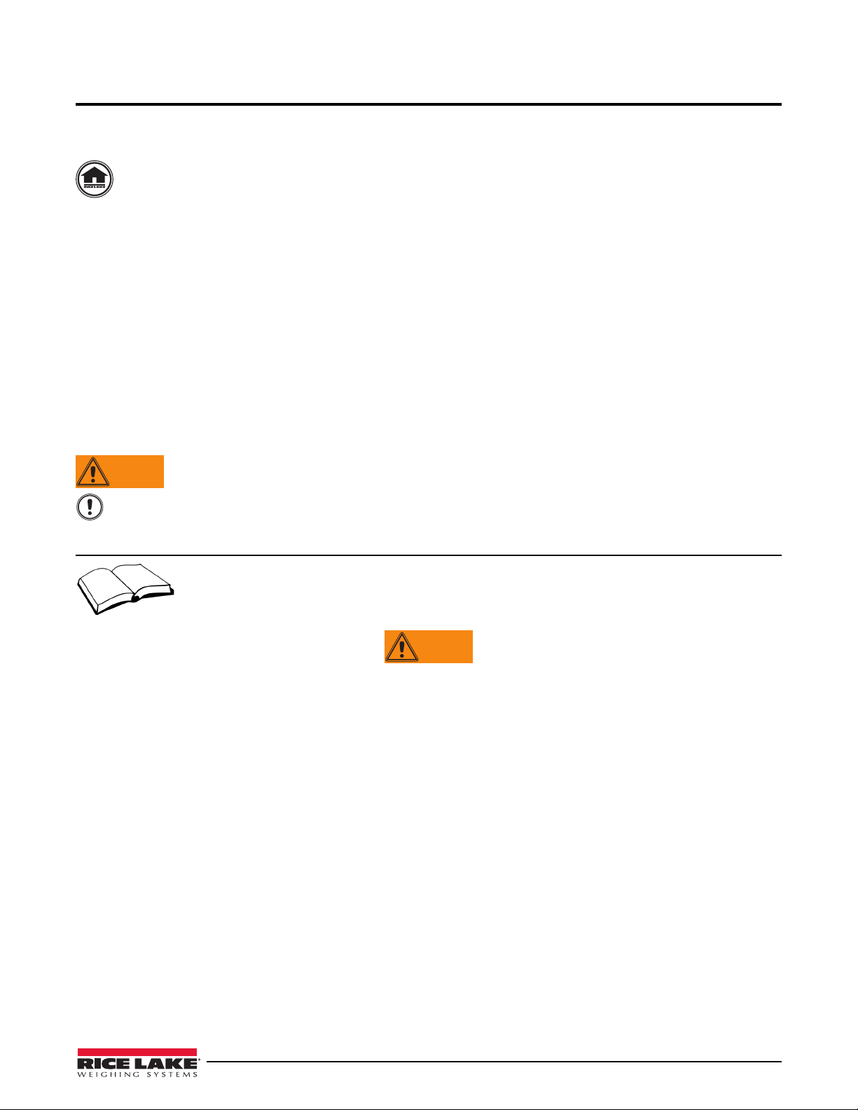
1.2 10" x 10" and 12" x 12" SL Models
Overload Protection Springs
Lift up Protection Screw
Overload Protection Screw
All seven models of the 10" x 10" and 12"x12" SL series have stainless steel covers and frame systems. All models
use a single point load cell. The 10, 20, 30, 50, and 100 lb models come standard with a potted single point load cell
that offers extra protection against water infiltration but is not designed for washdown use. The 30, 50, and 100 lb
models can also be supplied with an RL1140 stainless steel load cell. Extra load cell protection is also available in
optional stainless steel “clamshells” which enclose the load cell. See Section 5.0 for information about clamshell
installation. All load cells come with
The SL series scales use a sensitive 4-point, spring-plate suspension to minimize shock and overload damage
susceptible of light-capacity scales. The system uses a bolt and an overload protection spring at each of four
loading points beneath the top cover (see Figure 1-1). Each spring is set for a specific tension so that it will
compress to prevent overload damage. If a potentia
at that corner compresses. When the spring compresses, the load is taken off the load cell. This eliminates the
possibility of overloading the load cell. Likewise, if a load more than 150% of total capacity is placed anywhere on
the deck, the springs will compress and remove the load from the load cell.
In addition to the overload protection spring, the SL models inc
beneath the load cell to help prevent overload damage.
To protect the load cell from being acciden
spider, a lift up protection screw is incorporated into the design (see Figure 1-2).
10 feet of cable.
Figure 1-1. Overload Springs
lly damaging load is placed on a corner of the scale, the spring
orporate a load cell overload protection screw
tally forced upward and damaged by improperly lifting the scale by the
2 Benchmark Series Single Point Bench Scales
Figure 1-2. Lift up Protection Screw
Page 7
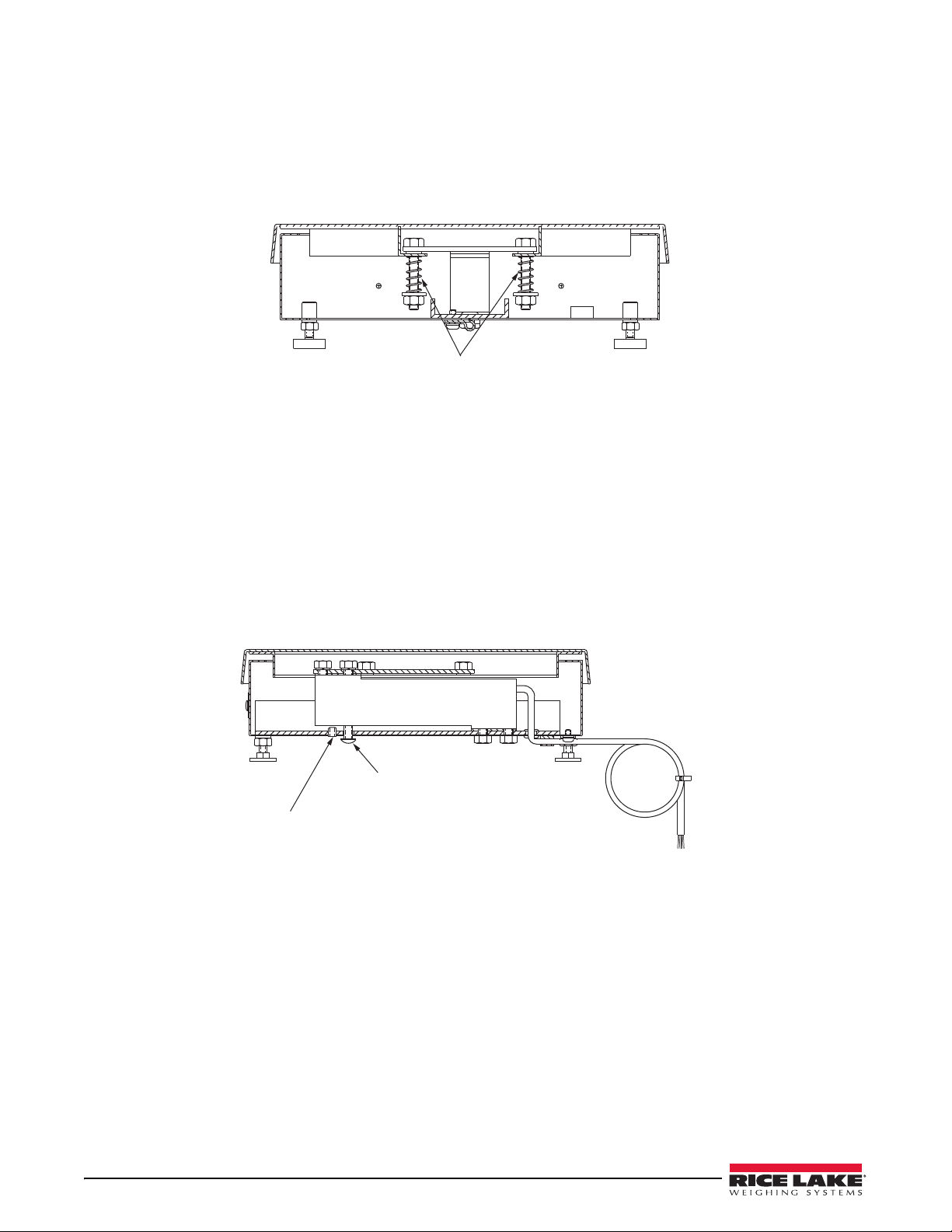
1.3 12", 18" and 24" Models
Top Frame
Overload Protection Screw
Overload Stops
Larger models in the series use mild steel frames and stainless steel deck covers for light washdown with a damp
sponge. All models are available with mild steel or optional stainless steel underbody frame construction. The
standard load cell is a single point load cell. Options include a stainless steel RL1140 load cell for 12" x 12" and
12" x 18" models and protective stainless steel clamshells for all models using a single point load cell. All load
cells come with 10 feet of cabling.
Figure 1-3. 12" x 12" With Overloads
These medium-capacity bench scales provide overload protection for the load cell by positive stops located beneath
each corner of the top frame (see Figure 1-3). These stops are set at the factory for 100% of scale capacity
Additional overload protection is provided by
damage.
an overload screw beneath the load cell to help prevent shock
.
1.4 12" x 18" Stainless Steel
The 12" x 18" model has a stainless steel cover and underbody frame to meet USDA requirements and make it
ideal for washdown use. The 12" x 18: comes standard with a single point load cell; a stainless steel load cell is
optional for both the 50 lb and 100 lb models. Extra load cell protection is available with the optional stainless steel
“clamshell” that encloses the load cell. See Section 5.0 for information about clamshell installati
come with 10 feet of cabling.
These medium capacity bench scales provide overload protec
of the top frame. These stops are set at the factory for 100% of scale capacity. Additional overload protection is
provided by an overload screw beneath the load cell to help prevent shock damage.
tion with positive stops located beneath each corner
on. All load cells
Introduction 3
Page 8
1.5 Specifications
1.5.1 10" x 10" and 12" x 12" SL Models
Load Cell: Potted single point
(5 lb is not potted)
Potted single point, stainless steel load
cell
cell optional on 30, 50, and 100 lb
models
Rated Output: 0.91 mV/V
Maximum Overload: 200%
Overload Protection: Spring loaded spider
Cable Length: 10 ft. (3 m) – 6 wire shielded
Output Impedance (ohms): 350
Compensated
Temperature Range: -10°C/14°F to +50°C/122°F
Safe Temperature Range:-30°C/-22°F to +70°C/158°F
Dimensions/Capacities:
1.5.2 12" x 18" Stainless Steel Model
Load Cell: Potted single point
Potted single point, stainless steel load
cell
optional on 50 lb and 100 lb models
Rated Output: 0.91 mV/V
Maximum Overload: 200%
Overload Protection: 5 point, independently adjusted
Cable Length: 10 ft. (3 m) – 6 wire shielded
Output Impedance (ohms): 350
Compensated
Temperature Range: -10°C/14°F to +50°C/122°F
Safe Temperature Range:-30°C/-22°F to +70°C/158°F
Dimensions/Capacities:
1.5.3 12", 18" and 24" Models
Load Cell: 12"x12" and 12"x18":
Potted single-point
18"x18", 18"x24" and 24"x24":
Overload Protection: 5 point, independently adjusted
Cable Length: 10 ft. (3 m) – 6 wire shielded
Rated Output: 0.91 mV/V
Output Impedance: 350
Maximum Overload: 200%
Compensated
Temperature Range: -10°C/14°F to +50°C/122°F
Safe Temperature Range:-30°C/-22°F to +70°C/158°F
Dimensions/Capacities:
Size Capacity Height
10" x 10"/
254mm x 254mm
5 lb / 2.3 kg 3.15" / 80 mm
10 lb / 4.5 kg 3.15" / 80 mm
20 lb / 9.1 kg 3.15" / 80 mm
30 lb / 13.6 kg 3.15" / 80 mm
12" x 12"/
305mm x 305mm
30 lb / 15 kg 3.25" / 92 mm
50 lb / 25 kg 3.25" / 92 mm
100 lb / 50 kg 3.25" / 92 mm
Table 1-1. 10" x 10" and 12" x 12" SL Model Sizes
Size Capacity Height
12" x 18" /
305mm x 457mm
50 lb / 25 kg 4.00" / 102mm
100 lb / 50 kg 4.00" / 102mm
Table 1-2. 12" x 18" Stainless Steel Model Sizes
Size Capacity Height
12" x 12" /
305mm x 305mm
30 lb / 13.6 kg 3.62" / 92mm
50 lb / 25 kg
100 lb / 50 kg
12" x 18" /
305mm x 457mm
50 lb / 25 kg 3.62" / 92mm
100 lb / 50 kg
18" x 18" /
457mm x 457mm
50 lb / 25 kg 5.25" /
133mm
100 lb / 50 kg
150 lb / 75 kg
200 lb / 100 kg
250 lb / 125 kg
300 lb / 150 kg
500 lb / 250 kg
1000 lb / 500
kg
18" x 24" /
457mm x 610mm
50 lb / 25 kg 5.25" /
133mm
100 lb / 50 kg
150 lb / 75 kg
200 lb / 100 kg
250 lb / 125 kg
300 lb / 150 kg
500 lb / 250 kg
1000 lb / 500
kg
24" x 24" /
610mm x 610mm
100 lb / 50 kg 5.25" /
133mm
150 lb / 75 kg
200 lb / 100 kg
250 lb / 125 kg
300 lb / 150 kg
500 lb / 250 kg
1000 lb / 500
kg
Table 1-3. 12", 18, and 24" Model Sizes
4 Benchmark Series Single Point Bench Scales
Page 9

2.0 Installation
Important
For 6-wire operation: For 4-wire operation:
6-Wire Color Code Function
Red +Signal
White - Signal
Green + Excitation
Black - Excitation
Blue + Sense
Brown - Sense
Yellow or Bare Shield
Table 2-1. Load Cell Wiring - 6 Wire
4-Wire Color Code Function
Red + Signal
White - Signal
Green and Blue* + Excitation
Black and Brown* - Excitation
Yellow or Bare Shield
* Connect Sense and Excitation wires together
if using 4-wire system without sense leads.
Table 2-2. Load Cell Wiring - 4 Wire
2.1 Leveling Scale
Remove the scale from the shipping container and place it in the desired location. Lift off the deck cover and locate
the bubble level. Adjust the four corner feet until the scale is level and all feet contact the support surface so the
scale does not rock. Lock the jam nuts on the feet when the final level is correct.
2.2 Connecting the Load Cell Cable
All models come with 10 feet of color-coded load cell cable.
Do not cut this cable. The load cell is temperature-compensated for an exact cable length of 10 feet.
See your indicator manual to determine the proper load cell cable input connectors. Use the following color codes
to wire the load cell cable.
2.3 Grounding the Scale Base
Bench scales can build up a static electricity charge during weighing operations. If powerful enough, this charge
can travel through the load cell cable to the indicator. To prevent this, all bench scales should be adequately
grounded so that static charges and transient electrical surges can drain directly to ground. Recommended practice
is to connect the scale base to an AC ground circuit using at least #12 wire. All BenchMark scales have either a
grounding screw or a hole for such a grounding screw located on the bottom of the lower frame for this purpose.
Installation 5
Page 10

3.0 Calibration
It is recommended that the scale be “exercised” by loading it to near capacity two or three times before calibration
to be certain that everything is seated. To calibrate your BenchMark:
1. With no load on scale, place the indicator in its calibration mode and perform a zero calibration.
2. Place test weights on platform equal to 70%–100% of scale’s capacity. If several weights are used, they
distribute them evenly around the platform.
3. Perform a span calibration.
4. Remove the test weights and check the zero reading. If necessary, repeat the calibration process.
See the indicator manual for the specific indicator calibration procedure.
6 Benchmark Series Single Point Bench Scales
Page 11

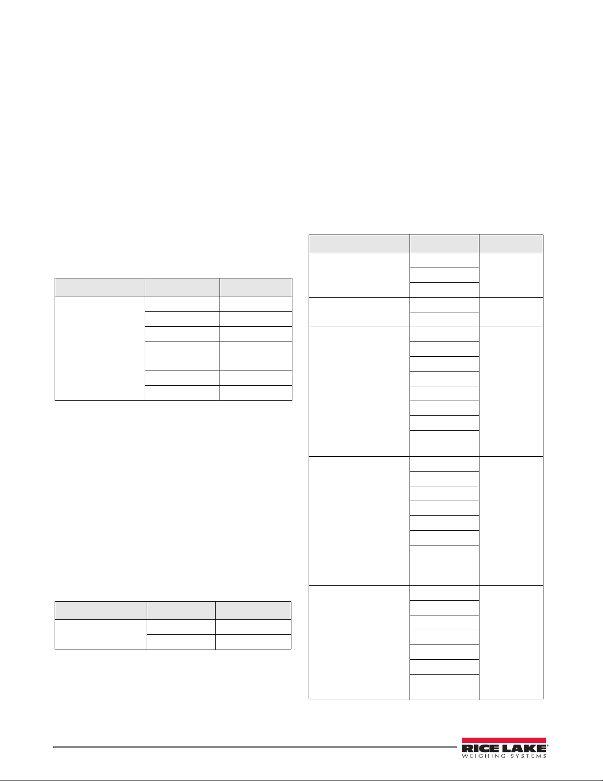
4.0 Troubleshooting Guide
Use the following troubleshooting tips for the Benchmark scale if necessary.
Symptom Probable Cause Remedy
No display Power disconnected Connect power
Cable cut or disconnected Repair cable
Signal leads incorrectly wired at indicator Connect according to the manual
Display starts at zero Incorrect load cell c
Faulty indicator Service indicator
Erratic Weight display Vibration near the scale Remove the source of the vibration, or adjust
Scale not level Level the scale
Water damage to the load cell or cable Replace the load cell
Faulty indicator Service the indicator
Loose load cell screws Tighten to correct torque
Faulty load cell Test and replace if necessary
Consistently low weight Indicator not properly adjusted to zero Zero indicator correctly
Scale deck cover binding Obtain adequate clearance
Overload stops set too high Reset the stops correctly
Indicator not calibrated for scale Calibrate the scale
Faulty load cell Test and replace if necessary
able connections Connect according to the manual
gital averaging of indicator to minimize erratic
di
display
Table 4-1. Benchmark Troubleshooting Table
Troubleshooting Guide 7
Page 12

5.0 Load Cell Replacement
Important
Lift up
Protection
Screw
Overload
Protection
Screw
Load Cell Screw
Load Cell Screw
Top Sub-Assembly
Load Plate / Spider
Top Cover
Scale Model Spring Length "H"
10 x 10 - 5 Lb 1.06
10 x 10 - 10 Lb .94
10 x 10 - 20 Lb .97
10 x 10 - 30 Lb 1.43
12 x 12 - 30 Lb 1.43
12 x 12 - 50 Lb 1.12
12 x 12 - 100 Lb 1.16
Table 5-1. Overload Spring Length
H ±.0 2
Figure 5-2. Spring Height
5.1 10"x10" and 12"x12" SL Models
1. Unplug AC power from indicator and disconnect load cell cable from indicator.
2. Lift off scale top cover.
3. Locate two upper load cell
Do not remove four spring-loaded screws that attach load plate to spider assembly.
4. Lift off load plate/spider assembly as a unit.
5. Remove spacer between load plate and load cell and set it aside.
screws. Use 7/16" wrench to unscrew and remove those two load cell screws.
6. Turn scale over and back off overload protection screw one complete turn. Completely unscrew and
remove lift up protection screw.
7. Use 7/16" wrench to unscrew and remove two lower load ce
removed from scale. Do not lose shim beneath load cell.
8. Thread cable of replacement load cell through rubber grommet. P
two lower load cell screws. Torque to 80 in-lb.
9. Replace lift up protection screw by screwing it in
10. Turn scale right side up. Position spacer on load cell, then place load plate/spider assembly into position.
Screw in
two upper load cell screws. Torque to 80 in-lb.
11. Using an accurate caliper, check compressed spring le
necessary, adjust spring length to specifica
necessary.
12. Connect load cell cable to indicator.
13. Recalibrate scale as described in Section 3.0.
14. Adjust overload protection screw on bottom of scale by
on top cover, centered on platform. Use a hex wrench to screw in overload protection screw until it touches
load cell, then back off 1/6 turn. Recheck calibration.
8 Benchmark Series Single Point Bench Scales
Figure 5-1. Load Cell Mount Diagram
ll screws. The load cell and cable can now be
osition load cell on shim and screw in
until it lightly bottoms, then back it off 1/4 turn.
ngth on four overload springs (Figure 5-2). If
tions shown in Tabl e 5-1. Replace top cover and re-level scale if
loading scale to 125% capacity. Place this weight
Page 13

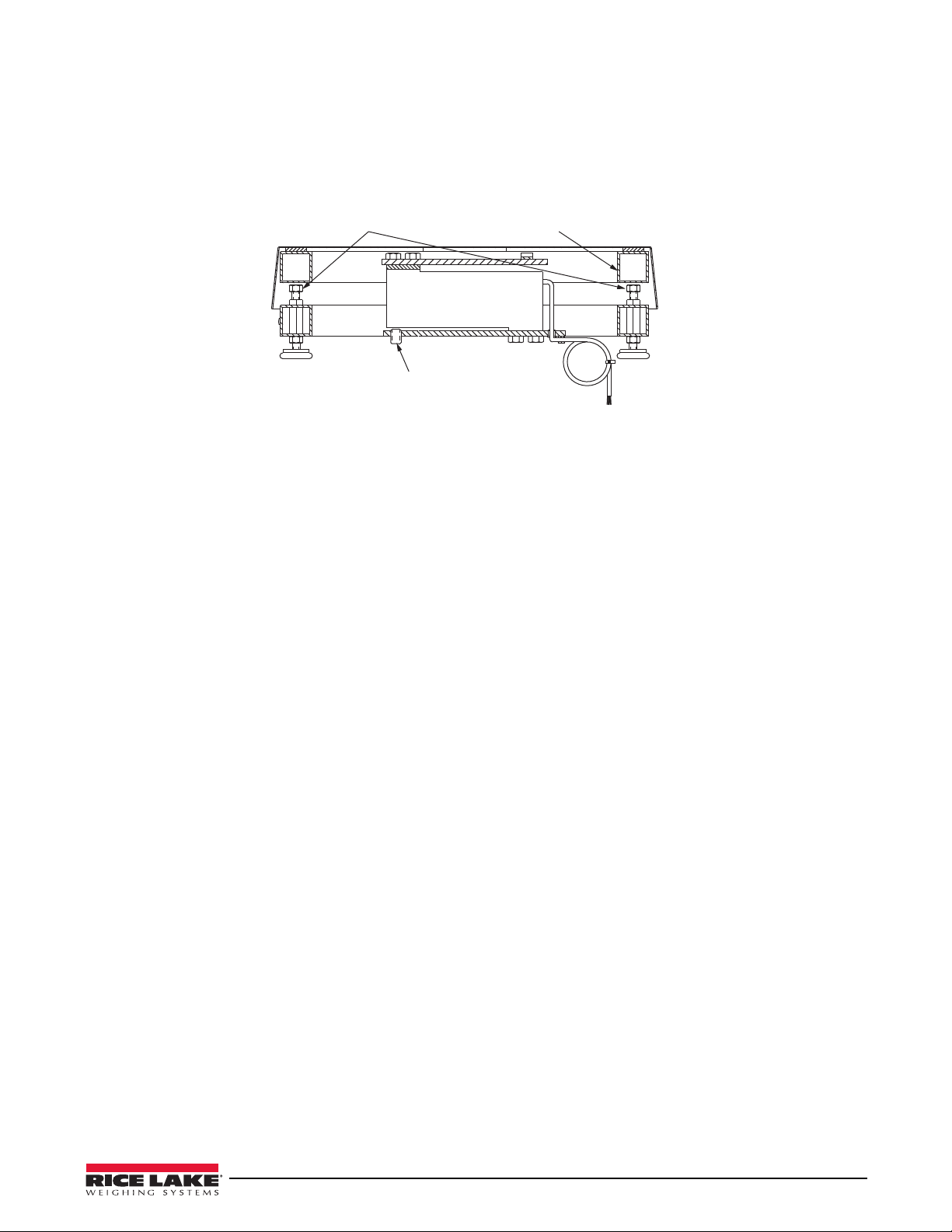
5.2 12", 18", and 24" Models
Overload Stop
Screws
Overload
Protection Screw
Load Cell Screws
Load Cell
Screws
Load Plate
Top Frame
1. Unplug AC power from indicator and disconnect load cell cable from indicator.
2. Lift off scale top cover.
3. Remove two load cell screws.
4. Lift off top spider.
5. Remove spacer plate and set it aside.
Figure 5-2. 12" x 12" Load Cell Mount
6. Loosen the four overload stop screws and turn each screw in one turn to provide ample clearance for the
new load cell. Turn scale over and back off overload protection screw one complete turn to provide
clearance.
7. Unscrew and remove lower load cell screws. Depending on model of scale, there will be eit
lower load cell screws.
8. Remove bottom shim beneath loa
d cell and set it aside.
9. Remove load cell and cable from scale.
10. Thread cable of replacement load cell through rubber grommet.
11. Position bottom shim directly beneath load cel
l and screw in lower load cell screws. Torque to 80 in-lbs for
12" x 12" and 12" x 18" scales, to 120 in-lb for 18" x 18", 18" x 24", and 24" x 24" scales.
12. Turn scale right side up. Position spacer plate on load cell, then
place top spider into position.
13. Screw in four upper load cell screws. Torque to 80 in-lbs for 12" x 12" and 12" x 18" scales, to 120 in-lb
fo
r 18" x 18", 18" x 24", and 24" x 24" scales.
14. Connect load cell cable to indicator.
15. Recalibrate scale as described in Section 3.0 of this manual.
16. Adjust overload protection screw on bottom of scale by
loading scale to 125% capacity. Place this weight
on top cover, centered on platform. Use a hex wrench to screw in overload protection screw until it touches
the load cell, then back off 1/6 turn. Recheck calibration.
17. To reset corner overload stop screws, load top spider ove
r one corner with approximately 30% of scale
capacity. Adjust screw under that corner to just touch top frame. Place a drop of a non-permanent,
high-strength locking compound such as LOCTITE
®
on the thread. Back screw off slightly so it is not
touching.
her two or four
LOCTITE is a registered trademark of the Loctite Corporation
Load Cell Replacement 9
Page 14

5.3 Installing Protective Clamshells
Important
UPPER
CLAM SHELL
LOWER
CLAM
SHELL
Stainless steel enclosures called clamshells are available to provide extra protection for the load cell of every
BenchMark scale. All clamshells are pre-drilled for load cell screws, overload screws, and cables. Any existing
load cell shims or spacers are installed inside the clamshells.
1. The lower clamshell fits inside the upper cl
part of it touches the load cell, then tighten the lower load cell screws to the specifications given
Section 5.1 or Section 5.2.
When installing the upper clam shell, position it so there is clearance on all sides to prevent any binding
problems with the lower clam shell.
2. Tighten the upper load cell screws to the required torque.
3. When installation is complete
, reset all overload protection screws as described in Section 5.1 or
Section 5.2.
4. Calibrate the scale according to the proce
amshell and is installed first. Position the clamshell so that no
dure described in Section 3.0.
Figure 5-3. Clamshell Enclosure
10 Benchmark Series Single Point Bench Scales
Page 15

6.0 Replacement Parts
Section BB (Enlarged)
Top View of Scale
with cover
18
19
20
21
23
22
26
27
24
25
2
3
4
5
7
8
9
10
11
13
14
15
16
17
A
A
B
B
12
Section AA (Enlarged)
6.1 10" x 10" and 12" x 12" SL and SL/HE Series
Figure 6-1. 10 x 10 and 12 x 12 SL and SL/HE Parts Illustration
Replacement Parts 11
Page 16

Item Part No. Description Qty.
2 14920 Screw, Overload Protection, 8 -32UNC x 1/4, SS 1
3 35128 Foot, 1/4 - 20 NC x 1 3/16 SS 4
4 14645 Jam Nut, Foot 1/4 - 20, SS 4
5 19086 Bottom Subassembly, (2 lb – 30 lb, 10 in x 10 in) 1
35066 Bottom Subassembly, (30 lb – 100 lb, 12 in x 12 in) 1
7 52342 Label, Bench Scale 1
8 19091 Cover, Top, 10 x 10 SS 1
35069 Cover, Top, 12 x 12 SS 1
9 19088 Spider, Top, 10 x 10 1
35068 Spider, Top, 12 x 12 1
10 15148 Lockwasher 1/4 SS 4
11 21948 Screw, Load Cell, 1/4 - 20 x 5/8 SS 4
12 15410 Bubble Level, Plastic, 15 mm 1
13 Load cell 1
14 15132 Lockwasher, #8, SS 1
15 14857 Pan Head Screw, 8 - 32 x 1/4 SS 1
16 15408 Rubber Grommet, 3/16 ID x 1/2 OD 1
17 16141 Cable Tie, 8" 1
18 14984 Cap screw (2 lb-20 lb models) 4
21947 Cap screw (30 lb model) 4
35199 Cap screw (50 lb-100 lb models) 4
19 15412 Spring, overload (2 lb model) 4
21945 Spring, overload (5 lb model) 4
15416 Spring, overload (10 lb model) 4
21946 Spring, overload (20 lb model) 4
21944 Spring, overload (30 lb model) 4
35086 Spring, overload (50 lb model) 4
35200 Spring, overload (100 lb model) 4
20 15149 Flat Washer, 1/4 type A, SS 4
21 14634 Nut, Nylon Insert, 1/4-20, SS 4
22 19089 Load Cell Shim, SS 1
23 15409 Plastic Wire Clamp 1
24 19090 Load Plate, (2 lb – 30 lb, 10 in x 10 in) 1
35067 Load Plate, (30 lb – 100 lb, 12 in x 12 in) 1
25 15150 Washer, Rubber 4
26 15138 Washer, #8, SS 1
27 14862
Screw, 8 - 32 x 3/8 SS 1
Table 6-1. 10 x 10 and 12 x 12 SL and SL/HE Parts List
12 Benchmark Series Single Point Bench Scales
Page 17

6.2 12" x 12" and 12" x 18" Models, Mild Steel
Top View of 12" Scale Series with cover
removed to show location of rubber pads
13
14
12
11
9
10
8
7
6
4
3
2
1
19
10
9
17
16
15
Section AA (Enlarged)
20
AA
Figure 6-2. 12" x 12" and 12" x 18" Mild Steel Parts Illustration
Replacement Parts 13
Page 18

Item Part No. Description Qty.
1 35128 Foot, 1/4-20 NC x 1 3/16 4
2 14645 Jam Nut, Foot 4
3 32993 Frame, Bottom, 12" X
32992 Frame, Bottom, 12" X
4 52342 Label, Bench Scale 1
6 14739 Bolt, Overload, 12" X
7 19092 Cover, Top, 12" X
19093 Cover, Top, 12" X
8 26408 Bumper, Round Self Adhesive 12
9 15147 Washer, Locking, 1/4 4
10 14962 Screw Cap, 12" X
11 19089 Spacer, Load Cell 1
12 15410 Spirit Level Bubble, Plastic 1
13 Load Cell 1
14 19132 Frame, Top, 12" X
19134 Frame, Top, 12" X
15 16141 Cable Tie 1
16 15409 Plastic Wire Clamp 1
17 15418 Rubber Grommet, 3/16 X 1/2 od 1
19 14918 Overload Protection Screw, 8-32 X 1/4 1
20 19139 Square Insert Guide 8
12" 1
18" 1
12" 4
12" 1
18"
18" 4
12" 1
18" 1
Table 6-2. 12" x 12" and 12" x 18" Mild Steel Parts List
14 Benchmark Series Single Point Bench Scales
Page 19

6.3 12" x 18" Model, Stainless Steel
Top View of Scale with
cover removed
4
24
18
15
16
19
21
20
14
11
8
22
3
2
1
17
9
10
12
7
Figure 6-3. 12" x 18" Stainless Steel Parts Illustration
Replacement Parts 15
Page 20

Item Part No. Description Qty.
1 35128 Foot, Bench Scale, 1/4-20 NC 4
2 14645 Nut, Jam, 1/4-20 NC, Hex 4
3 32795 Bottom Sub-assembly 1
4 52342 Label, Bench Scale 1
7 32957 Top C o v e r, 1 2 " X 18" 1
8 Load Cell 1
9 15148 Washer, Lock, 1/4 Regular 4
10 14963 Screw, Cap, 1/4-20 NC X 3/4 4
11 35082 Shim, Load Cell 1
12 15410 Level, Spirit Bubble 1
14 32797 Spider Top, 12" x
15 16141 Cable Tie, 8" Nyl
16 15418 Grommet, Rubber 1
17 14920 Screw, Set, 8-32 NC x 1/4, Hex 1
18 15409 Clamp, Cable, No. 8 Hole 1
19 15138 Washer, Plain, Std No. 8 1
20 15132 Washer, Lock, No. 8, Type A 1
21 14862 Screw, Mach, 8-32 NC x 3/8 1
22 19089 Shim, Load Cell 1
24 26408 Bumper, Self Adhesive 4
18" 1
on 1
Table 6-3. 12" x 18" Stainless Steel Parts List
16 Benchmark Series Single Point Bench Scales
Page 21

6.4 18" x 18", 18" x 24" and 24" x 24" Models, Mild and Stainless Steel
15
16182021241
2
3
4
6
7
8
11 19 12
17
9
10
14
22
25
26
27
8
Figure 6-4. 18" x 18", 18" x 24" and 24" x 24" Models Parts Illustration
Item Part No. Description Qty.
1 19141 Foot, 3/8-16 X .78 4
2 14649 Jam Nut, Foot Ms 4
14653 Jam Nut, Foot Ss 4
3 49766 Frame Bottom, 18" X
49768 Frame Bottom, 18" X
49770 Frame Bottom, 18" X
49772 Frame Bottom, 18" X
49774 Frame Bottom, 24" X
49776 Frame Bottom, 24" X
19108 Frame Bottom, 18" X
19109 Frame Bottom, 18" X
19110 Frame Bottom, 18" X
19111 Frame Bottom, 18" X
19112 Frame Bottom, 24" X
19114 Frame Bottom, 24" X
4 52342 Label Roll, 4" X
6 14742 Bolt, 3/8-16 NC X 1, Hex Head 4
7 19094 Cover, Top, 18" X
19095 Cover, Top, 18" X
19096 Cover, Top, 24" X
18", MS (RL1260/PMW16 Load Cell) 1
18", SS (RL1260/PMW16 Load Cell) 1
24", MS (RL1260/PMW16 Load Cell) 1
24", SS (RL1260/PMW16 Load Cell) 1
24", MS (RL1260/PMW16 Load Cell) 1
24", SS (RL1260/PMW16 Load Cell) 1
18", MS (RL1250 Load Cell) 1
18", SS (RL1250 Load Cell) 1
24", MS (RL1250 Load Cell) 1
24", SS (RL1250 Load Cell) 1
24", MS (RL1250 Load Cell) 1
24", SS (RL1250 Load Cell) 1
1.25" 1
18" 1
24" 1
24" 1
Table 6-4. 18" x 18", 18" x 24" and 24" x 24" Models Parts List
Replacement Parts 17
Page 22

Item Part No. Description Qty.
8 26407 Bumper, Self Adhesive 20
9 15153 Washer, Lock, 5/16 Regular, MS 8
15154 Washer, Lock, 5/16 Regular, SS 8
10 26668 Screw, Cap, 5/16-18 NC x 3/4, Hex, MS 4
26669 Screw, Cap, 5/16-18 NC x 3/4, Hex, SS 4
26667 Screw, Cap, 5/16-18 NC x 1, hex, MS 4
26670 Screw, Cap, 5/16-18 NC x 1, hex, SS 4
11 49785 Plate, Washer, MS (RL1260/RLPMW16 load cell) 1
49786 Plate, Washer, SS (RL1260/RLPMW16 load cell) 1
19102 Plate, Washer, MS (RL1250 load cell) 1
19103 Plate, Washer, SS (RL1250 load cell) 1
12 15410 Level, Spirit Bubble 1
14 19140 Insert, Glide, Square 8
15 49765 Frame, Top, 18" x 18", MS (RL1260/RLPMW16 Load Cell) 1
49767 Frame, Top, 18" x 18", SS (RL1260/RLPMW16 Load Cell) 1
19116 Frame, Top, 18" x 18", MS (RL1250 Load Cell) 1
19117 Frame, Top, 18" x 18", SS (RL1250 Load Cell) 1
19118 Frame, Top, 18" x 24", MS (RL1250 Load Cell) 1
19119 Frame, Top, 18" x 24", SS (RL1250 Load Cell) 1
49769 Frame, Top, 18" x 24", MS (RL1260/RLPMW16 Load Cell) 1
49771 Frame, Top, 18" x 24", SS (RL1260/RLPMW16 Load Cell) 1
49773 Frame, Top, 24" x 24", MS (RL1260/RLPMW16 Load Cell) 1
49775 Frame, Top, 24" x 24", SS (RL1260/RLPMW16 Load Cell) 1
19120 Frame, Top, 24" x 24", MS (RL1250 Load Cell) 1
19121 Frame, Top, 24" x 24", SS (RL1250 Load Cell) 1
16 16141 Cable, Tie, 8" Nylon 1
17 15409 Clamp, Cable, No. 8 Hole 1
18 15418 Grommet, Rubber 1
49788 Screw, Cap, 5/16-18 NC X 1 1/4, Hex, MS (RL1260 Load Cell) 4
49789 Screw, Cap, 5/16-18 NC X 1 1/4, Hex, SS (RL1260 Load Cell) 4
26667 Screw, Cap, 5/16-18 NC X 1, Hex, MS (RL1250 Load Cell) 4
26668 Screw, Cap, 5/16-18 NC X 3/4, Hex, MS (RL1250 Load Cell) 4
26669 Screw, Cap, 5/16-18 NC X 3/4, Hex, SS (RL1250 Load Cell) 4
20 49787 Shim Plate (RL1260/RLPMW16 Load Cell) 1
22264 Shim Plate (RL1250 Load Cell) 1
21 15045 Screw, Set, 1/2-20 NF X 1/2, Hex, MS 1
15047 Screw, Set, 1/2-20 NF X 1/2, Hex, SS 1
22 14858 Screw, Mach, 8-32 NC X 5/16, MS 1
14862 Screw, Mach, 8-32 NC X 3/8, SS 1
24 32849 Load Cell 1
25 35316 Screw, Cap, 1/4-20 NC X 2, Hex, MS 1
35199 Screw, Cap, 1/4-20 NC X 2, Hex, SS 1
26 15145 Washer, Plain, 1/4 Type A, MS 1
15149 Washer, Plain, 1/4 Type A, SS 1
27 14635 Nut, Lock, 1/4-20 NC, Hex, MS 1
14634 Nut, Lock, 1/4-20 NC, Hex, SS 1
Table 6-4. 18" x 18", 18" x 24" and 24" x 24" Models Parts List
18 Benchmark Series Single Point Bench Scales
Page 23

BenchMark Series Limited Warranty
Rice Lake Weighing Systems (RLWS) warrants that all RLWS equipment and systems properly installed by a
Distributor or Original Equipment Manufacturer (OEM) will operate per written specifications as confirmed by the
Distributor/OEM and accepted by RLWS. All systems and components are warranted against defects in materials
and workmanship for two years.
RLWS warrants that the equipment sold hereunder will conform to the current written specifications authorized by
RLWS. RLWS warrants the equipment against faulty workmanship and defective materials. If any equipment fails
to conform to these warranties, RLWS will, at its option, repair or replace such goods returned within the warranty
period subject to the following conditions:
• Upon discovery by Buyer of such nonconformity, RLWS will be given prompt written notice with a
detailed explanation of the alleged deficiencies.
• Individual electronic components returned to RLWS for warranty purposes must be packaged to
prevent electrostatic discharge (ESD) damage in shipment. Packaging requirements are listed in a
publication, “Protecting Your Components From Static Damage in Shipment,” available from RLWS
Equipment Return Department.
• Examination of such equipment by RLWS confirms that the nonconformity actually exists, and was
not caused by accident, misuse, neglect, alteration, improper installation, improper repair or improper
testing; RLWS shall be the sole judge of all alleged nonconformities.
• Such equipment has not been modified, altered, or changed by any person other than RLWS or its duly
authorized repair agents.
• RLWS will have a reasonable time to repair or replace the defective equipment. Buyer is responsible
for shipping charges both ways.
• In no event will RLWS be responsible for travel time or on-location repairs, including assembly or
disassembly of equipment, nor will RLWS be liable for the cost of any repairs made by others.
THESE WARRANTIES EXCLUDE ALL OTHER WARRANTIES, EXPRESSED OR IMPLIED, INCLUDING WITHOUT
LIMITATION WARRANTIES OF MERCHANTABILITY OR FITNESS FOR A PARTICULAR PURPOSE. NEITHER RLWS
NOR DISTRIBUTOR WILL, IN ANY EVENT, BE LIABLE FOR INCIDENTAL OR CONSEQUENTIAL DAMAGES.
RLWS AND BUYER AGREE THAT RLWS’S SOLE AND EXCLUSIVE LIABILITY HEREUNDER IS LIMITED TO REPAIR
OR REPLACEMENT OF SUCH GOODS. IN ACCEPTING THIS WARRANTY, THE BUYER WAIVES ANY AND ALL OTHER
CLAIMS TO WARRANTY.
SHOULD THE SELLER BE OTHER THAN RLWS, THE BUYER AGREES TO LOOK ONLY TO THE SELLER FOR
WARRANTY CLAIMS.
No terms, conditions, understanding, or agreements purporting to modify the terms of this warranty shall have any
legal effect unless made in writing and signed by a corporate officer of RLWS and the Buyer.
© Rice Lake Weighing Systems, Inc. Rice Lake, WI USA. All Rights Reserved.
RICE LAKE WEIGHING SYSTEMS • 230 WEST COLEMAN STREET • RICE LAKE, WISCONSIN 54868 • USA
Replacement Parts 19
Page 24

For More Information
Web Site
• Frequently Asked Questions (FAQs) at
• http://www.ricelake.com/faqs.aspx
Contact Information
Hours of Operation
Knowledgeable customer service representatives are available 6:30 a.m. - 6:30 p.m. Monday through Friday and 8
a.m. to 12 noon on Saturday. (CST)
Telephone
• Sales/Technical Support 800-472-6703
• Canadian and Mexican Customers 800-321-6703
• International 715-234-9171
Immediate/Emergency Service
For immediate assistance call toll-free 1-800-472-6703 (Canadian and Mexican customers please call
1-800-321-6703). If you are calling after standard business hours and have an urgent scale outage or emergency,
press 1 to reach on-call personnel.
Fax
Fax Number 715-234-6967
E-mail
• U.S. sales and product information at
• prodinfo@ricelake.com
• International (non-U.S.) sales and product information at
• intlsales@ricelake.com
Mailing Address
Rice Lake Weighing Systems
230 West Coleman Street
Rice Lake, WI 54868 USA
20 Benchmark Series Single Point Bench Scales
Page 25

Page 26

230 W. Coleman St. • Rice Lake, WI 54868 • USA
www.ricelake.com www.ricelake.mx www.ricelake.eu www.ricelake.co.in m.ricelake.com
U.S. 800-472-6703 • Canada/Mexico 800-321-6703 • International 715-234-9171 • Europe +31 (0)26 472 1319
© Rice Lake Weighing Systems 10/23/14 PN 22125 Rev D
 Loading...