

Page 1

In-Motion Belt Scale System
To be the best by every measure
#$
Version 2.00
Installation & Operation
Manual
94805
Page 2

Page 3

Contents
Technical training seminars are available through Rice Lake Weighing Systems.
Course descriptions and dates can be viewed at www.ricelake.com or obtained
by calling 715-234-9171 and asking for the training department.
Integrator Hardware Setup ..............................................................................................................................26
1.0 Introduction and Overview........................................................................................................... 1
1.1 Belt Conveyor Scale System Components . . . . . . . . . . . . . . . . . . . . . . . . . . . . . . . . . . . . . . . . . . . . . 1
1.2 Operation . . . . . . . . . . . . . . . . . . . . . . . . . . . . . . . . . . . . . . . . . . . . . . . . . . . . . . . . . . . . .
1.3 Application Brief . . . . . . . . . . . . . . . . . . . . . . . . . . . . . . . . . . . . . . . . . . . . . . . . . . . . . . . . . .
1.4 Selecting a Mounting Location . . . . . . . . . . . . . . . . . . . . . . . . . . . . . . . . . . . . . . . . . . . . . . . . . . . .
1.5 Poor Choices for Belt Scale Installations. . . . . . . . . . . . . . . . . . . . . . . . . . . . . . . . . . . . . . . . . . . . . . 12
6 Handbook 44 Requirements for Belt Scales . . . . . . . . . . . . . . . . . . . . . . . . . . . . . . . . . . . . . . . . . . . 13
1.
2.0 Integrator Hardware Installation ............................................................................................... 14
2.1 Unpacking and Assembly . . . . . . . . . . . . . . . . . . . . . . . . . . . . . . . . . . . . . . . . . . . . . . . . . . . . . . . . . 14
2.2 Scale Carriage Installation. . . . . . . . . . . . . . . . . . . . . . . . . . . . . . . . . . . . . . . . . . . . . . . . . . . . .
2.3 Junction Box Installation . . . . . . . . . . . . . . . . . . . . . . . . . . . . . . . . . . . . . . . . . . . . . . . . . . . . . .
2.4 Attaching the Idlers to the Scale Carriage . . . . . . . . . . . . . . . . . . . . . . . . . . . . . . . . . . . . . . . . . . . . . 20
2.5 Speed Sensor Installation . . . . . . . . . . . . . . . . . . . . . . . . . . . . . . . . . . . . . . . . . . . . . . . . . . . . . .
2.6 Scale Carriage Replacement Parts . . . . . . . . . . . . . . . . . . . . . . . . . . . . . . . . . . . . . . . . . . . . . . . . . . 24
3.0 Integrator Hardware Setup ........................................................................................................ 26
3.1 Enclosure Disassembly. . . . . . . . . . . . . . . . . . . . . . . . . . . . . . . . . . . . . . . . . . . . . . . . . . . . . . . . . . . 26
3.2 Cable Connections . . . . . . . . . . . . . . . . . . . . . . . . . . . . . . . . . . . . . . . . . . . . . . . . . . . . . . . . . .
3.3 Enclosure Reassembly . . . . . . . . . . . . . . . . . . . . . . . . . . . . . . . . . . . . . . . . . . . . . . . . . . . . . . . .
3.4 CPU Board Removal . . . . . . . . . . . . . . . . . . . . . . . . . . . . . . . . . . . . . . . . . . . . . . . . . . . . . . . . .
3.5 Fuse Replacement . . . . . . . . . . . . . . . . . . . . . . . . . . . . . . . . . . . . . . . . . . . . . . . . . . . . . . . . . .
3.6 Battery Replacement . . . . . . . . . . . . . . . . . . . . . . . . . . . . . . . . . . . . . . . . . . . . . . . . . . . . . . . .
3.7 Parts Kit Contents . . . . . . . . . . . . . . . . . . . . . . . . . . . . . . . . . . . . . . . . . . . . . . . . . . . . . . . . . .
3.8 Replacement Parts and Assembly Drawings. . . . . . . . . . . . . . . . . . . . . . . . . . . . . . . . . . . . . . . . . . . 35
. . . . . . . . . 6
. . . . . . . 7
. . 9
. . . . 14
. . . . 16
. . . 22
. . . . 26
. . . 32
. . . 33
. . . . 33
. . . . 33
. . . . 34
4.0 Supervisor Mode Parameters.................................................................................................... 38
4.1 Admin. Passcode (numeric) . . . . . . . . . . . . . . . . . . . . . . . . . . . . . . . . . . . . . . . . . . . . . . . . . . . . . . . 39
4.2 Scale Capacity . . . . . . . . . . . . . . . . . . . . . . . . . . . . . . . . . . . . . . . . . . . . . . . . . . . . . . . . . . .
4.3 Load Cell MV . . . . . . . . . . . . . . . . . . . . . . . . . . . . . . . . . . . . . . . . . . . . . . . . . . . . . . . . . . . .
4.4 Total Load Cell Build . . . . . . . . . . . . . . . . . . . . . . . . . . . . . . . . . . . . . . . . . . . . . . . . . . . . . . . .
4.5 Rate Unit Time . . . . . . . . . . . . . . . . . . . . . . . . . . . . . . . . . . . . . . . . . . . . . . . . . . . . . . . . . . .
4.6 Filter (s). . . . . . . . . . . . . . . . . . . . . . . . . . . . . . . . . . . . . . . . . . . . . . . . . . . . . . . . . . . . . .
4.7 Filter Threshold (divisions) . . . . . . . . . . . . . . . . . . . . . . . . . . . . . . . . . . . . . . . . . . . . . . . . . . . . .
4.8 Speed Unit Time. . . . . . . . . . . . . . . . . . . . . . . . . . . . . . . . . . . . . . . . . . . . . . . . . . . . . . . . . . . .
4.9 Fixed Speed . . . . . . . . . . . . . . . . . . . . . . . . . . . . . . . . . . . . . . . . . . . . . . . . . . . . . . . . . . . . .
4.10 Unit of Measure . . . . . . . . . . . . . . . . . . . . . . . . . . . . . . . . . . . . . . . . . . . . . . . . . . . . . . . . . . .
4.11 Unit of Rate. . . . . . . . . . . . . . . . . . . . . . . . . . . . . . . . . . . . . . . . . . . . . . . . . . . . . . . . . . . . .
4.12 Rate Count By . . . . . . . . . . . . . . . . . . . . . . . . . . . . . . . . . . . . . . . . . . . . . . . . . . . . . . . . . . . .
4.13 Totalizer Count By . . . . . . . . . . . . . . . . . . . . . . . . . . . . . . . . . . . . . . . . . . . . . . . . . . . . . . . . .
4.14 Load Display Units . . . . . . . . . . . . . . . . . . . . . . . . . . . . . . . . . . . . . . . . . . . . . . . . . . . . . . . . .
4.15 Load Count By . . . . . . . . . . . . . . . . . . . . . . . . . . . . . . . . . . . . . . . . . . . . . . . . . . . . . . . . . . . .
4.16 Auto Zero Tracking (%) . . . . . . . . . . . . . . . . . . . . . . . . . . . . . . . . . . . . . . . . . . . . . . . . . . . . . . .
4.17 Auto Zero Tracking Percentage. . . . . . . . . . . . . . . . . . . . . . . . . . . . . . . . . . . . . . . . . . . . . . . . . . . . 41
18 Dead Band . . . . . . . . . . . . . . . . . . . . . . . . . . . . . . . . . . . . . . . . . . . . . . . . . . . . . . . . . . . . . . .
4.
. . . . . . 40
. . . . . . 40
. . . . 40
. . . . . . 40
. . . . . . . . . 40
. . . . 40
. . . . 40
. . . . . . 40
. . . . 40
. . . . . . 40
. . . . 41
. . . . 41
. . . . 41
. . . . 41
. . . 41
. . . . 41
Page 4

4.19 Cal. Test Weight. . . . . . . . . . . . . . . . . . . . . . . . . . . . . . . . . . . . . . . . . . . . . . . . . . . . . . . . . . . . . . . 42
4.20 Cal. Test Chain . . . . . . . . . . . . . . . . . . . . . . . . . . . . . . . . . . . . . . . . . . . . . . . . . . . . . . . . . . .
4.21 Calibration Load . . . . . . . . . . . . . . . . . . . . . . . . . . . . . . . . . . . . . . . . . . . . . . . . . . . . . . . . . . .
4.22 Material Factor . . . . . . . . . . . . . . . . . . . . . . . . . . . . . . . . . . . . . . . . . . . . . . . . . . . . . . . . . .
4.23 Zero Error% . . . . . . . . . . . . . . . . . . . . . . . . . . . . . . . . . . . . . . . . . . . . . . . . . . . . . . . . . . . .
4.24 Zero Counts . . . . . . . . . . . . . . . . . . . . . . . . . . . . . . . . . . . . . . . . . . . . . . . . . . . . . . . . . . . .
4.25 Span Error% . . . . . . . . . . . . . . . . . . . . . . . . . . . . . . . . . . . . . . . . . . . . . . . . . . . . . . . . . . . . .
4.26 Idler Spacing . . . . . . . . . . . . . . . . . . . . . . . . . . . . . . . . . . . . . . . . . . . . . . . . . . . . . . . . . . .
4.27 Number of Idlers . . . . . . . . . . . . . . . . . . . . . . . . . . . . . . . . . . . . . . . . . . . . . . . . . . . . . . . . . .
4.28 Belt Test Revolutions . . . . . . . . . . . . . . . . . . . . . . . . . . . . . . . . . . . . . . . . . . . . . . . . . . . . . . .
4.29 Pulses per Revolution. . . . . . . . . . . . . . . . . . . . . . . . . . . . . . . . . . . . . . . . . . . . . . . . . . . . . . . . .
4.30 Belt Length . . . . . . . . . . . . . . . . . . . . . . . . . . . . . . . . . . . . . . . . . . . . . . . . . . . . . . . . . . . .
4.31 Pulses Per Unit Measure . . . . . . . . . . . . . . . . . . . . . . . . . . . . . . . . . . . . . . . . . . . . . . . . . . . . . .
4.32 Test Duration . . . . . . . . . . . . . . . . . . . . . . . . . . . . . . . . . . . . . . . . . . . . . . . . . . . . . . . . . . .
4.33 Tons per Pulse (output) . . . . . . . . . . . . . . . . . . . . . . . . . . . . . . . . . . . . . . . . . . . . . . . . . . . . . . .
4.34 Pulse Duty Cycle (in seconds) . . . . . . . . . . . . . . . . . . . . . . . . . . . . . . . . . . . . . . . . . . . . . . . . . . .
4.35 Alarm - Low Rate Alarm Value (%) . . . . . . . . . . . . . . . . . . . . . . . . . . . . . . . . . . . . . . . . . . . . . . . . . 43
4.36 Maximum Speed Value . . . . . . . . . . . . . . . . . . . . . . . . . . . . . . . . . . . . . . . . . . . . . . . . . . . . . . . .
4.37 Low Rate Alarm Bit . . . . . . . . . . . . . . . . . . . . . . . . . . . . . . . . . . . . . . . . . . . . . . . . . . . . . . . . . .
4.38 High Rate Alarm Bit . . . . . . . . . . . . . . . . . . . . . . . . . . . . . . . . . . . . . . . . . . . . . . . . . . . . . . . .
4.39 Speed Alarm Bit . . . . . . . . . . . . . . . . . . . . . . . . . . . . . . . . . . . . . . . . . . . . . . . . . . . . . . . . . . .
4.40 Totalizer Pulse Bit. . . . . . . . . . . . . . . . . . . . . . . . . . . . . . . . . . . . . . . . . . . . . . . . . . . . . . . .
4.41 Fill Output Bit . . . . . . . . . . . . . . . . . . . . . . . . . . . . . . . . . . . . . . . . . . . . . . . . . . . . . . . . . . .
4.42 Remote Print Input Bit . . . . . . . . . . . . . . . . . . . . . . . . . . . . . . . . . . . . . . . . . . . . . . . . . . . . . . . .
4.43 Print Output Port . . . . . . . . . . . . . . . . . . . . . . . . . . . . . . . . . . . . . . . . . . . . . . . . . . . . . . . . . .
4.44 Print Format . . . . . . . . . . . . . . . . . . . . . . . . . . . . . . . . . . . . . . . . . . . . . . . . . . . . . . . . . . . .
4.45 Stream Output Port . . . . . . . . . . . . . . . . . . . . . . . . . . . . . . . . . . . . . . . . . . . . . . . . . . . . . . . . . .
4.46 Stream Format . . . . . . . . . . . . . . . . . . . . . . . . . . . . . . . . . . . . . . . . . . . . . . . . . . . . . . . . . . . .
4.47 Clear Totalizer with Print . . . . . . . . . . . . . . . . . . . . . . . . . . . . . . . . . . . . . . . . . . . . . . . . . . . . .
4.48 Remote Totalizer Reset Input . . . . . . . . . . . . . . . . . . . . . . . . . . . . . . . . . . . . . . . . . . . . . . . . . . . .
4.49 Integrator Identification . . . . . . . . . . . . . . . . . . . . . . . . . . . . . . . . . . . . . . . . . . . . . . . . . . . . . .
4.50 Preact Length . . . . . . . . . . . . . . . . . . . . . . . . . . . . . . . . . . . . . . . . . . . . . . . . . . . . . . . . . . . .
4.51 Enable Batching . . . . . . . . . . . . . . . . . . . . . . . . . . . . . . . . . . . . . . . . . . . . . . . . . . . . . . . . . . .
4.52 Analog 1 Mode . . . . . . . . . . . . . . . . . . . . . . . . . . . . . . . . . . . . . . . . . . . . . . . . . . . . . . . . . . .
4.53 Analog 2 Mode . . . . . . . . . . . . . . . . . . . . . . . . . . . . . . . . . . . . . . . . . . . . . . . . . . . . . . . . . . .
4.54 Setting Time and Date . . . . . . . . . . . . . . . . . . . . . . . . . . . . . . . . . . . . . . . . . . . . . . . . . . . . . . . .
4.55 Interfacing a PLC to the Belt Scale System . . . . . . . . . . . . . . . . . . . . . . . . . . . . . . . . . . . . . . . . . . 45
. . . . 42
. . . . 42
. . . . . . 42
. . . . . . 42
. . . . . . 42
. . . . 42
. . . . . . 42
. . . . 42
. . . . 42
. . 43
. . . . . . 43
. . 43
. . . . . . 43
. . 43
. 43
. 43
. . 43
. . . . 43
. . . . 43
. . . . . . 43
. . . . . . 43
. . 44
. . . . 44
. . . . . . 44
. . 44
. . . . 44
. . . . 44
. 44
. . . . 44
. . . . 44
. . . . 44
. . . . 45
. . . . 45
. . 45
5.0 Calibration ................................................................................................................................. 46
5.1 Speed Sensor Calibration . . . . . . . . . . . . . . . . . . . . . . . . . . . . . . . . . . . . . . . . . . . . . . . . . . . . . . . . 46
5.2 Integrator Calibration . . . . . . . . . . . . . . . . . . . . . . . . . . . . . . . . . . . . . . . . . . . . . . . . . . . . . . . .
5.3 Complete System Calibration Test Used In Conjunction with integrator Calibration . . . . . . . . . . . . . 49
. . . . 47
6.0 Run Sequence ............................................................................................................................ 53
6.1 Target Settings . . . . . . . . . . . . . . . . . . . . . . . . . . . . . . . . . . . . . . . . . . . . . . . . . . . . . . . . . . . . . . . . 53
6.2 Diagnostics . . . . . . . . . . . . . . . . . . . . . . . . . . . . . . . . . . . . . . . . . . . . . . . . . . . . . . . . . . . .
6.3 Reset Totalizer . . . . . . . . . . . . . . . . . . . . . . . . . . . . . . . . . . . . . . . . . . . . . . . . . . . . . . . . . . .
6.4 Start Fill . . . . . . . . . . . . . . . . . . . . . . . . . . . . . . . . . . . . . . . . . . . . . . . . . . . . . . . . . . . . .
. . . . . . . 54
. . . . . . 54
. . . . . . . . . 54
7.0 Handbook 44 Requirements for Belt-Conveyor Scales ............................................................. 55
7.1 Reference Test . . . . . . . . . . . . . . . . . . . . . . . . . . . . . . . . . . . . . . . . . . . . . . . . . . . . . . . . . . . . . . . . 55
7.2 Conditions of Test . . . . . . . . . . . . . . . . . . . . . . . . . . . . . . . . . . . . . . . . . . . . . . . . . . . . . . . . . .
2 BCi Installation Manual
. . . . 55
Page 5

8.0 Maintenance .............................................................................................................................. 56
8.1 Maintenance Checkpoints . . . . . . . . . . . . . . . . . . . . . . . . . . . . . . . . . . . . . . . . . . . . . . . . . . . . . . . . 56
8.2 Belt Scale Troubleshooting Tips . . . . . . . . . . . . . . . . . . . . . . . . . . . . . . . . . . . . . . . . . . . . . . . . . . .
8.3 BCi Integrator Troubleshooting Tips . . . . . . . . . . . . . . . . . . . . . . . . . . . . . . . . . . . . . . . . . . . . . . . . . 59
. 58
9.0 Appendix .................................................................................................................................... 60
9.0 BCi Permanent Field Record . . . . . . . . . . . . . . . . . . . . . . . . . . . . . . . . . . . . . . . . . . . . . . . . . . . . . . 62
9.0 BCi integrator Specifications. . . . . . . . . . . . . . . . . . . . . . . . . . . . . . . . . . . . . . . . . . . . . . . . . . . .
. . . 64
Page 6

4 BCi Installation Manual
Rice Lake continually offers web-based video training on a growing selection
of product-related topics at no cost. Visit www.ricelake.com/webinars.
Page 7
About This Manual
Intern et
Warning
This manual is intended for use by service technicians responsible for installing and servicing the BCi In-Motion
Belt Scale System Installation & Operation Manual.
This manual can be viewed and downloaded from the Rice Lake Weighing Systems web
site at
company.
Some procedures described in this manual require work in and around working parts of the
belt scale. These procedures are to be performed by qualified service personnel
www.ricelake.com. Rice Lake Weighing Systems is an ISO 9001 registered
only .
1.0 Introduction and Overview
A belt conveyor scale is a device that continuously measures bulk material as it moves along a conveyor. The
system requires two general parameters to operate:
•It needs to know the weight of the material being moved along the conveyor belt
It needs to know the speed at which it’s moving along the conveyor belt.
•
The weight of the material on the belt is determin
and then subtracting the average weight of the unloaded belt. The speed at which the material is moving is
determined by measuring the speed of an idler or wheel in contact with the conveyor belt. The weight and speed
is combined to give a running total and a rate of flow of the material. The correct operation of the scale system
requires the components to be installed correctly, periodically calibrated, and properly maintained.
Typical applications where a belt conveyor scale can be used are:
• Mining
• Quarries
• Bulk Material Blending
• Truck/Barge/Rail Loading
• Process Control Applications
A belt conveyor scale is also able to compute the tota
of time and while it is in motion.
The BCi In-Motion Belt Scale System is durable and one of the mos
handles capacities up to 10,000 tons per hour with unsurpassed accuracy. It’s innovative integrator fits a wide
variety of applications - from simple inventory reporting to automated load-out.
ed by weighing a section of conveyor belt loaded with material
l mass of the material that is conveyed over a given period
t accurate scales in its class. The BCi easily
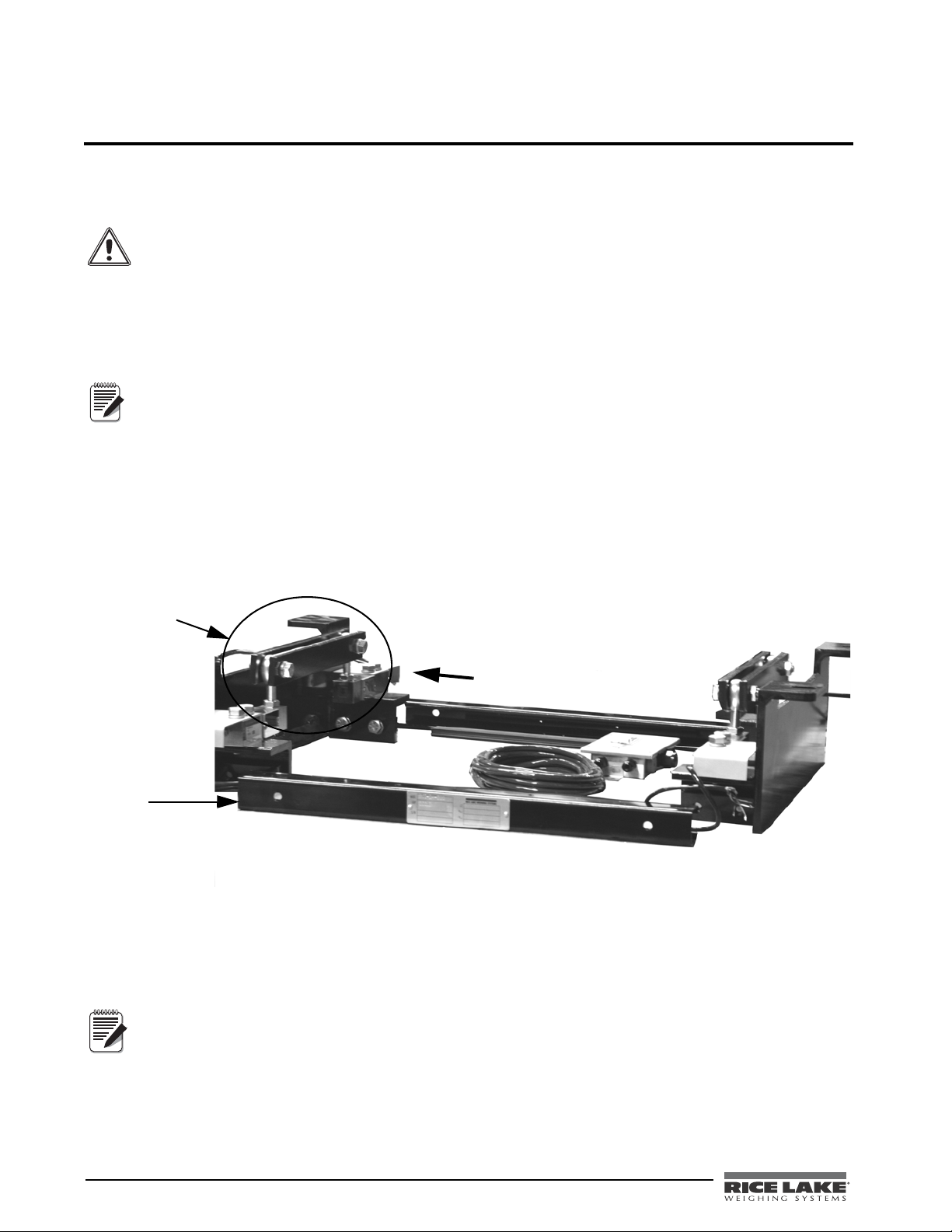
1.1 Belt Conveyor Scale System Components
The main components of a basic belt conveyor scale include:
• Scale carriage
• Load cells
• Belt travel pickup speed sensor (not shown)
• Electronic integrator
BCi Installation & Operation Manual - Introduction and Overview 1
Page 8
BCi Electronic Integrator
Load Cells
Scale Carriage
Figure 1-1. Component Parts of the BCi Belt Conveyor Scale System
2 BCi Installation & Operation Manual
Page 9
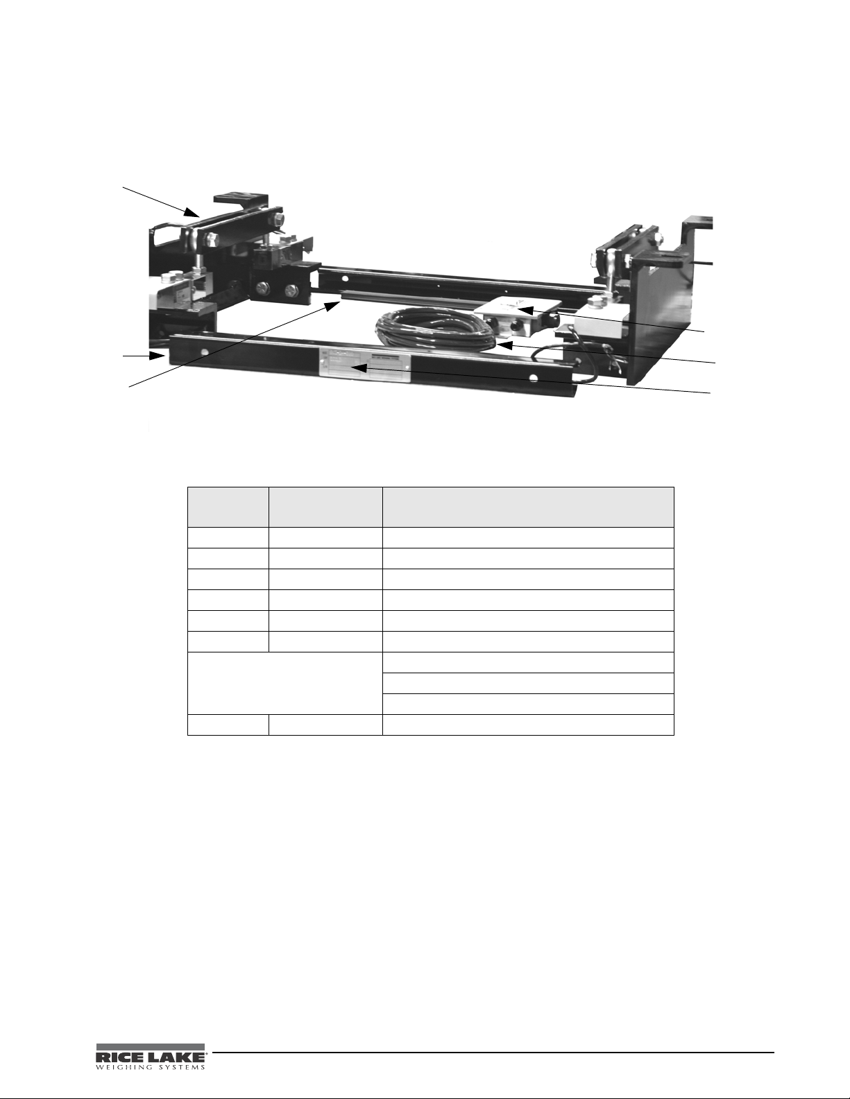
Scale Carriage
1
2
3
4
5
6
The scale carriage is mounted to a conveyor structure and transmits the forces resulting from the belt load and
directs those forces to the load sensor(s). The following picture and table illustrate the component parts shipped
with the scale carriage.
Figure 1-2. Scale Carriage Components
RLWS Part
Number
1 - - - - - End Plate Assembly (2)
2 - - - - - Uni-Strut Middle Bars (2)
3 - - - - - Uni-Strut Closure Strips (2)
4 38557 Home Run Cable (1)
5 88956 Junction Box w/ Grounding Lug (1)
6 16863 Metal Serial Tag (1)
Nuts (2)
Bolts (2)
Lock Washers (2)
97416 Shim Kit
Description (Qty.)
Table 1-1. Scale Carriage Component Part Numbers
BCi Installation & Operation Manual - Introduction and Overview 3
Page 10

Load Cells
There are four strain gauge load cells located on the corners of the weigh idler. These sensors support the weight
of the conveyor belt and the material moving along on the belt. The weight signals from the load cells are
combined and processed by the integrator.
Figure 1-3. Load Cell Location on Scale Carriage
4 BCi Installation & Operation Manual
Page 11

Belt Travel Speed Wheel - Optional
The belt travel speed wheel is located near the weigh frame. Positive contact must be maintained between the roll
and the belt for proper operation. The speed sensor should never come in contact with material that is being
conveyed along the belt nor the belt itself. The signal generated by the speed wheel is converted by the integrator
into a value that represents belt travel distance. Various devices used for sensing belt travel include AC and DC
generators, mechanical belt or chain drives, photo-optical segmented disks, and electromagnetic pulse
generators. Installation procedures for the speed wheel are explained in detail on page 24. The graphic below
illustrates the major component parts of the speed wheel.
Figure 1-4. Speed Wheel
RLWS Part Number Description (Qty)
94969 Complete Speed Wheel Assembly (1)
96543 Speed Wheel (1) (wheel only)
94979 Speed Proximity Sensor (1)
94970 Speed Wheel Bracket Assembly (1) (wheel not included)
Cabling to integrator (1)
94980 U-Bolts (2)
21161 Splice Box (1)
98501 Expansion Cable - 20’
100038 Magnetic Shaft Encoder
Table 1-2. Speed Wheel Assembly Component Part Numbers
Magnetic Shaft Encoder - Optional
Another option besides the belt travel speed wheel is a magnetic shaft encoder which can also be used to
determine belt travel distance like the speed wheel. The magnetic shaft encoder should never come in contact
with material that is being conveyed along the belt nor the belt itself. The signal generated by the encoder is
converted by the integrator into a value that represents belt travel distance.
Figure 1-5. Magnetic Shaft Encoder
BCi Installation & Operation Manual - Introduction and Overview 5
Page 12
Electronic Integrator
13*/5
6/*54
40'5,&: 40'5,&:
40'5,&:
40'5,&: 40'5,&:
Outputs from the belt travel speed sensor and from the load cell carriage are combined in the integrator to
produce a running total of material passed over the belt conveyor scale. Using the BCi HMI as a calibrated
electronic integrator allows signals to be converted into values that represent the weight and speed of the material
that is traveling on the conveyor.
1.2 Operation
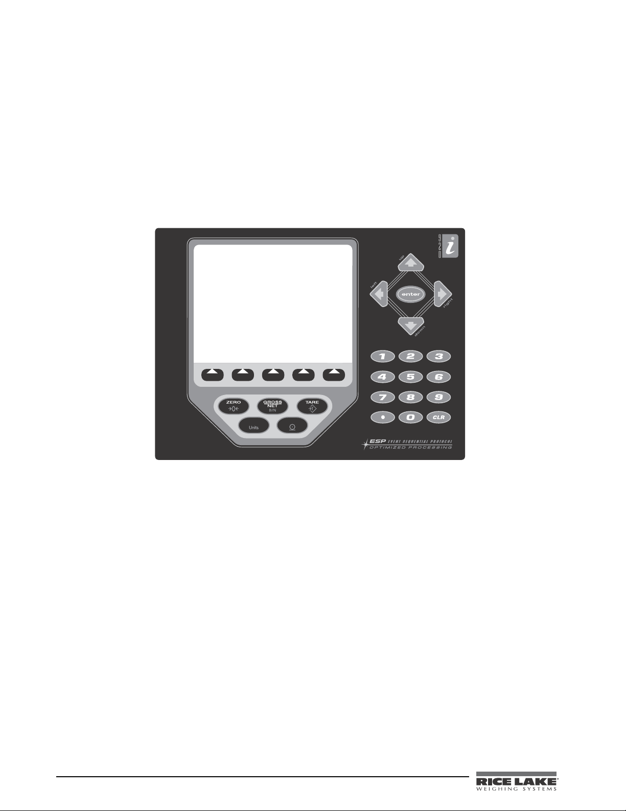
The BCi front panel, shown below consists of a 27-button keypad with a large backlit LCD display. The keys are
grouped as five configurable softkeys, five primary scale functions keys, four navigational keys, and numeric
entry keys. It should be noted that the scale parameters and calibration values cannot be changed without first
pressing the
settings. Pressing
TARE key and unlocking the parameters. After pressing the TARE key, press enter to unlock the
ZERO when the display is on the main menu will clear the Reset Total.
Figure 1-6. BCi Front Panel
The following sections describe the front panel key operation of the belt scale integrator.
Zero
This parameter will initiate the front panel zero mechanism. Periodic use of the zero parameter is required due to
weather conditions.
This will print the custom ticket if the print port is configured.
Reset Totalizer
Often during this operation of a belt scale, the totalizer will need to be reset. This is known as the reset totalizer.
Press the
operator will press
Diagnostics
Reset Totalizer softkey to access this parameter. The integrat or will prompt the user, “Clear Totalizer?” The
Yes to clear the totalizer, or No to leave the accumulated weight in the totalizer.
This softkey displays the current mV input, PPS (pulses per second from the speed sensor), current analog output
(if installed), current A/D counts, and the master total. This is just informational data that the operator or a
technician can use from troubleshooting purposes.
Supervisor Mode
Use this softkey to enter the Supervisor Mode. If there is no passcode configured the BCi will enter into the
Setup Mode. If a passcode is configured, the operator will need to enter the passcode before the BCi will switch
to the Supervisor Mode. To configure a passcode, see the Supervisor’s Parameters.
6 BCi Installation & Operation Manual
Page 13

1.3 Application Brief
There are four factors used to determine a suitable belt scale application on a given conveyor.
• Load cell size
• Belt speed
•Idler spacing
• Belt splicing
Load Cell Size
The capacity of the belt scale is rated on the maximum continuous load that can be carried across the weigh idler.
The capacity of the conveyor shou ld be known p rior to determining the components of the scale system. The load
cells should be sized to operate across a loading range with a marginal safety factor. The minimum net loading
should be greater than 10% of the rated capacity and the maximum loading should be less than 65%. The load
applied to the loadcell can be calculated with the following formula:
Net load = (conveyor capacity / belt speed) x idler spacing
Gross load = net load + (idler weight + belt weight + mounting hardware)
Examples:
Net load = (50,000 lbs per minute / 400 feet per minute) x 4 foot spacing
Net load = (125 lbs per foot) x 4 foot spacing
Net Load = 500 lbs.
Gross load = 500 lbs + (175 lb idler + 48 lb belt + 24 lbs hardware)
Gross Load = 747 lbs.
Net Load > 10% of total load cell capacity
(4) x 500 lb load cells x 10% = 200 lbs 500 lbs > 200 lbs (500 lb load cells are okay)
(4) x 1000 lb load cells x 10% = 400 lbs 500 lbs > 400 lbs (500 lb
(4) x 2000 lb load cells x 10% = 800 lbs 500 lbs > 800 lbs (2000 lb load cell
Gross Load < 65% of total load cell capacity
load cells are okay)
s are too large)
(4) x 250 lb load cells x 65% = 650 lbs 747 lbs > 650 lbs (250 lb load cells are too small)
(4) x 500 lb load cells x 65% = 1300 lbs 74
(4) x 1000 lb load cells x 65% = 2600 lbs 74
The example listed would require 500 lb or 1000 lb load
Belt Speed
7 lbs < 1300 lbs (500 lb load cells are okay)
7 lbs < 2600 lbs (1000 lb load cells are okay)
cells.
The belt speed is defined as the maximum velocity of the unloaded conveyor belt. The belt speed can be variable,
but for sizing requirements the maximum speed is required.
BCi Installation & Operation Manual - Introduction and Overview 7
Page 14
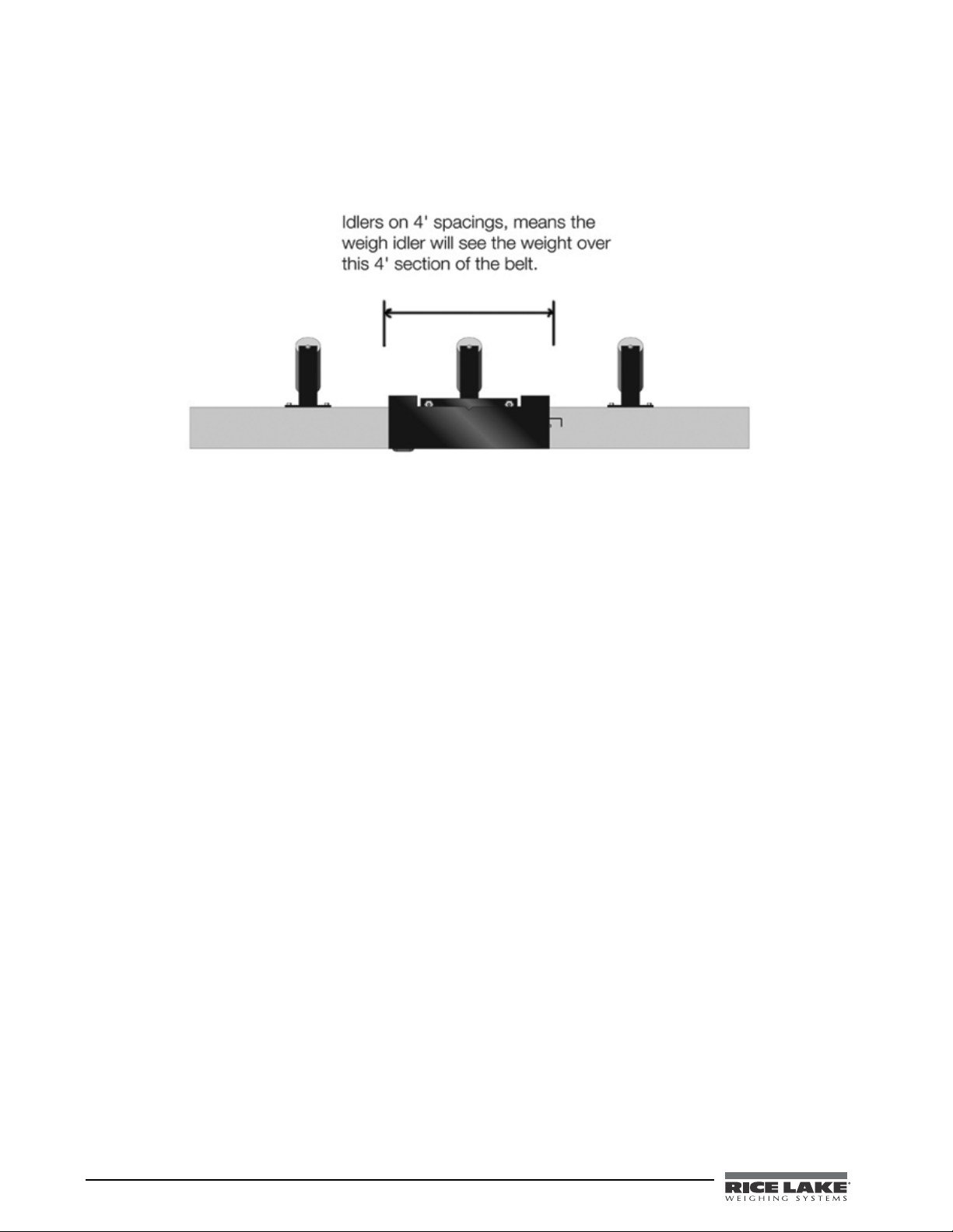
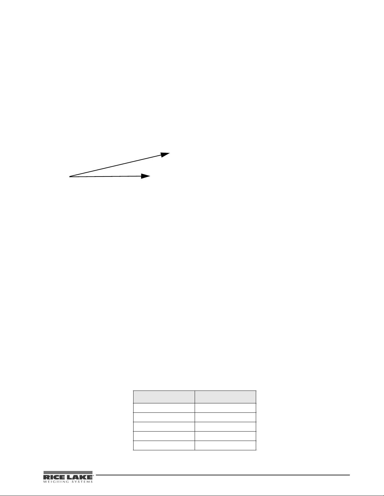
Idler Spacing
The spacing between idlers should conform to the recommendations of the idler manufacturer and the Conveyor
Equipment Manufacturer’s Association specifications. A general rule of thumb is the idler supports the belt half
the distance from the previous idler to half the distance to the following idler as shown in the example below.
Figure 1-7. Idler Spacing Example
The number of weigh idlers required to accurately weigh the material being conveyed is determined by the
velocity of the conveyor belt. The scale born time of the material should be greater than 400 mSec. If the belt
speed multiplied by the idler spacing is less than 400 mSec, the idler spacing must be increased or multiple weigh
idlers must be used. Scale born time can be calculated with the following formula:
Scale Time = (Idler Spacing / Belt Speed)
Example: Scale Ti
me = (4 feet / 8.33 fps) = 480 mSec
Belt Splicing
Belt splices also have a contributing factor in limiting the belt scale’s capacity. Mechanical belt splices can shock
load and damage load cells on high speed conveyors. Vulcanized splices are preferred for proper scale operation.
Figure 1-8. Mechanical Belt Splicing Example
8 BCi Installation & Operation Manual
Page 15
1.4 Selecting a Mounting Location
It is very important to select the right mounting location for the scale carriage along the conveyor structure and
the location of the speed sensor. There are several factors that must be taken into consideration when selecting a
mounting location. Those factors will determine the overall long-term and short-term accuracy you might expect.
Those factors include the following:
• Tension
• Uniform Belt Loading
• Single Load Point on Belt
• Material Slippage
• Convex Curves
• Concave Curves
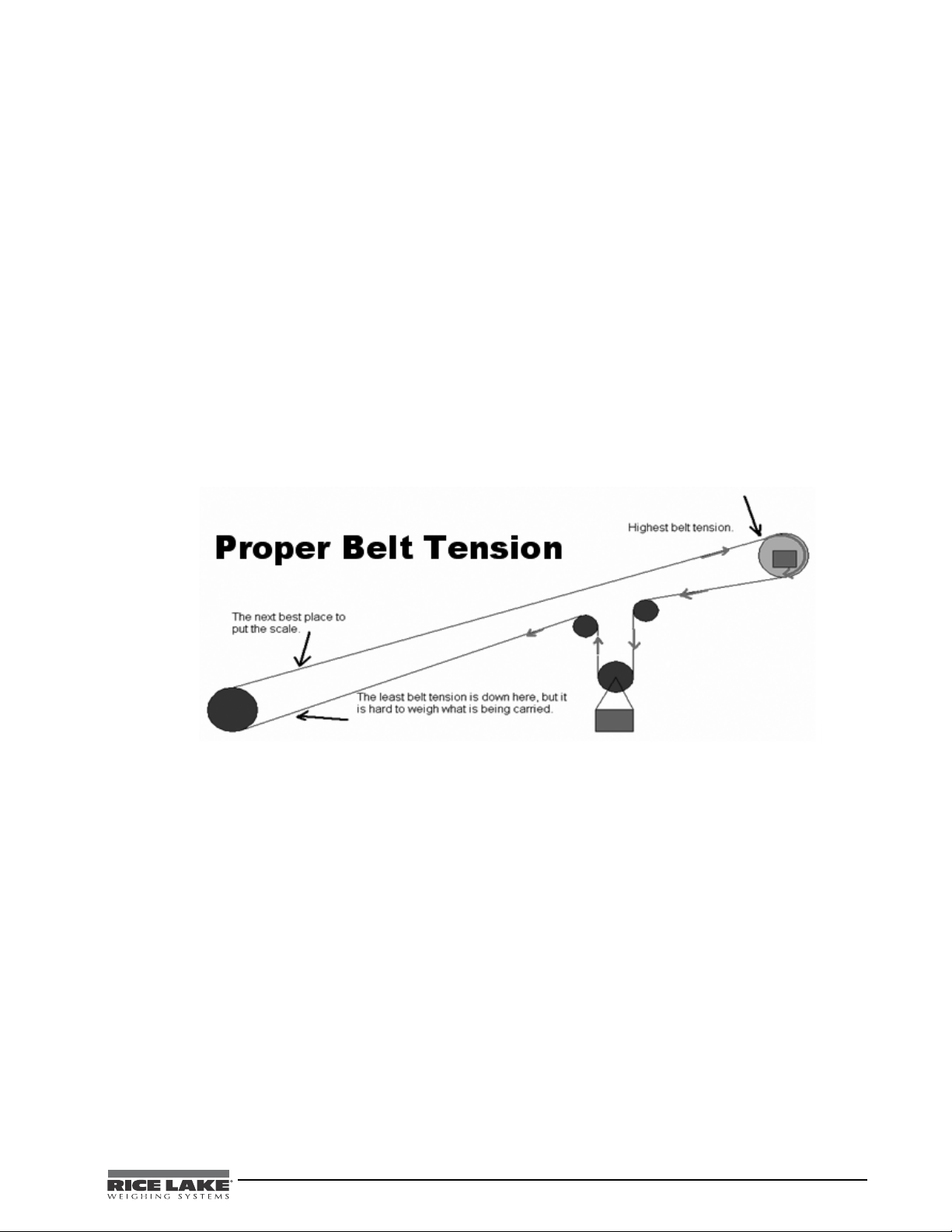
Tension
The transfer of weight along the conveyor belt can be greatly affected by belt tension. By locating the scale
carriage in an area of the conveyor with the least amount of tension, the scale will be more accurate and achieve
better performance. An ideal location to mount the scale carriage is near a tail section of the conveyor, but far
enough forward so as not to be influenced by infeed skirts boards, etc. Figure 1-9 illustrates the proper belt
tension.
•Trippers
• Speed Sensor Mounting Location
• Electronic Wiring Location
• Speed Wheel
• Troughing Angle
Figure 1-9. Proper Belt Tension Example
Uniform Belt Loading
It is desirable that the belt loading be as uniform as possible to prevent unequal shifts in material. To minimize
surges or feed variations, hoppers should be equipped with depth limiting gates or other flow control devices
such as a feeder.
Single Load Point on Belt
On high accuracy installations, the conveyor should be loaded at one and the same point. This assures constant
belt tension at the scale during all loading conditions.
Material Slippage
The belt scale system processes belt loading and belt travel to arrive at an accurate weight. Product speed must be
equal to the belt speed at the scale. So the conveyor speed and slope should not exceed that at which material
slippage occurs. This is typically less than a 20% pitch for most materials.
Convex Curves
Conveyors that have convex curves should be avoided or the scale should be located in a section of the conveyor
that is not affected by the curve.
Convex curves are permissible at a distance of 20 feet or a m
inimum of five idler spaces beyond the scale area
idlers.
BCi Installation & Operation Manual - Introduction and Overview 9
Page 16
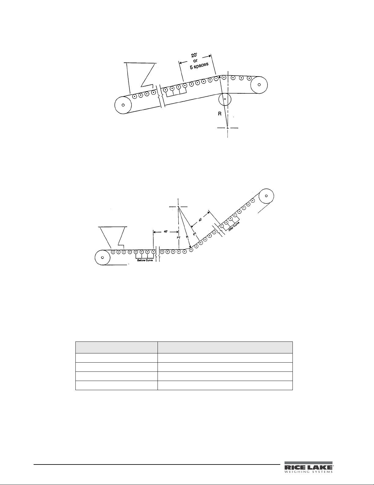
Figure 1-10. Convex Curved Conveyor
Concave Curves
Conveyors that have concave curves should be avoided or the scale should be located in a section of the conveyor
that is not affected by the curve. If there is a curve, the belt must remain in contact with the idler rollers at all
times for at least 20 feet (6m).
Figure 1-11. Concave Curved Conveyor
Trippers
Tripper belts, mechanical sweep samplers, training idlers, feed points, skirt boards and other device that also
affect belt tension should be located away from the scale carriage.
If the scale must be installed on a conveyor with a tripper, then the same rules apply as for an installation in a
ncave conveyor.
co
nce
The following table offers basic guidelines for minimum dista
s and applies to both horizontal and incline
conveyors.
Type of Conveyor Distance from Scale Carriage
End of skirt boards or feed point 15’ or 4 idler spaces whichever is greater
Training idler or sweep sampler 30’ or 8 idler spaces, whichever is greater
Tripper or concave curve 40’ from the first idler affected by the curve
Convex curve or head pulley 20’ or 5 idler spaces
Table 1-3. Distance Points from Conveyor to Scale Carriage
Speed Sensor or Magnetic Shaft Encoder Mounting Location - (Optional items)
The optional speed sensor location is not as critical as scale carriage location, however improper installation of
the speed sensor will significantly affect the performance of the scale system. The speed sensor must give an
accurate representation of the speed of the material and travel of the belt.
10 BCi Installation & Operation Manual
Page 17

The favorable location for the speed sensor is the tail roll of the conveyor, provided that the conveyor is not
driven from the tail, and that the tail roll is accessible.
Figure 1-12. Speed Sensor Pulley
If the tail roll is not accessible then the speed sensor can be mounted on a tailing wheel that rides on the return
side of the belt, or on a live shaft roller . If a trailing wheel is used, the wheel should be located on a section of the
belt in which belt vibration will not add movement to the wheel. The preferable location would be directly
opposite a conveyor return roll.
If a live shaft roller is installed to sense the belt speed, the roller
should have positive contact with the belt. The
preferred location would be between two retu rn idlers with the speed roller being installed on the top side of the
returning belt and the return idlers installed on the bottom side.
Electronic Wiring Location
The location for the electronics to be mounted is determined by accessibility, wire routing, and environment. The
scale electronics require a clean and stable 120 VAC supply. The enclosure for the electronics is rated NEMA
4X. The electronics can be mounted up to 2000’ away from the scale carriage provided the optional load cell
sense wiring is installed. If the electronics are to be installed within 200’ of the scale carriage, the optional sense
wiring is not required. To reduce the effects of signal interference, the scale signals should not be ru n in conduit
or cable trays in conjunction with high voltage cables.
are
The digital input and output signals
compatible with OPTO 22 G4 5VDC relay modules and can be
controlled with AC, DC or dry contact signals. The analog output signal for rate of flow can be wired for 0-10
VDC, 2-10 VDC, 0-20mA current or 4- 20mA current. The printer signal can be RS-232, RS-485, or 20 mA
current loop.
Speed Wheel
If an optional speed wheel is used, the wheel should be located on a section of the belt in which belt vibration
will not add movement to the wheel. The preferable location would be directly opposite a conveyor return roll.
Figure 1-13. Optional Speed Wheel Assembly
BCi Installation & Operation Manual - Introduction and Overview 11
Page 18
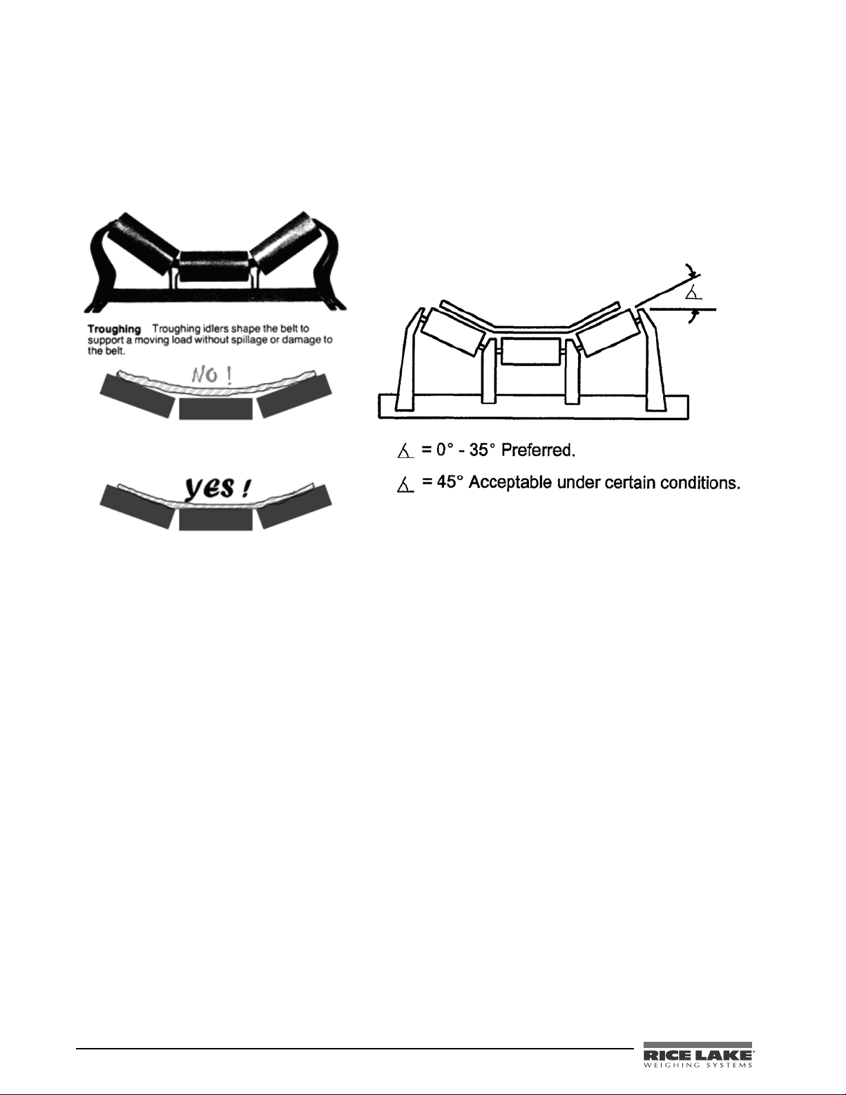
Troughing Angle
The use of idlers with steep troughing angles causes many problems. Not only does the bean or catenary effect of
the belt become more pronounced as the toughing increases, but the effect of idler misalignment is amplified as
well. The graphics below show an example of a correct and an incorrect troughing angles.
Troughing angles of 35 degrees or less are preferred for all h
igh accuracy installations. Troughing angles of 45
degrees are acceptable under certain conditions.
Figure 1-14. Troughing Angle Examples
1.5 Poor Choices for Belt Scale Installations
There are several instances where a belt scale installation would not be the best solution. The following list
points these out.
• Conveyors with multiple loading points
• Conveyors with convex or concave curves
• Conveyors with different stringer members i
• Conveyors that do not receive periodic inspections and housekeeping
• Conveyors where there is no facility to conduct a simulat
• Conveyors that are used in cold weather that are not i
• Tripper convey ors
• Radial stacking conveyors
• Applications where the belt scale results are compared w
• Applications where the belt scale weighment is subject to certific
Handbook 44 requirements.
• Applications where plant personnel are unwilling or unable to perfo
• Conveyors with more than 2-ply belting
• Conveyors that are installed outdoors, but are not equipped with a cover over the c
n troughing rolls
ed test
nstalled in a heated conveyor gallery
ith a marine draft survey
ation but the conveyor does not meet
rm routine conveyor maintenance
arry belt.
12 BCi Installation & Operation Manual
Page 19

1.6 Handbook 44 Requirements for Belt Scales
The following is a listing of various Handbook 44 requirements for belt scales.
• Minimum divisions shall not be greater than 0.1 of the minimum
• On test, the recorder must show the initial totalizer reading; the final tota
measure and the quantity delivered along with the time and date.
• The integrator master totalizer shall not be reset
• In the event of loss of power of up to 24 hours, the accumulated me
totalizer shall be retained in memory during that power loss.
• An audio or visual alarm indication shall be activated when the flow rate
in excess of 98% of the rated capacity.
• The totalizer can only advance when the belt conveyor
on the belt, the totalizer could not register).
• The master totalizer shall not be re-settable without breaking a security seal.
Means shall be provided that the totalizer reading shall be retained
•
event of a power failure.
• The belt scale integrator must factor in belt speed as a function
• Zero is to be limited to +/- 2% without breaking the security sea
• Auto zero mechanism shall be designed to operate only after a whole number of belt r
• An indication shall be provided for when the auto zero adjustment
• Belt speed device shall be designed so that there is no slip.
• An event logger must provide an audit trail of all calibration adjustment with a prin
demand. It shall have the capacity to retain records equal to ten times the number of sealable parameters
in the device, but not more than 1000 records are required, (ie: time and date of change; the parameter
value; the parameter ID).
• A zero circuit should provide for an average of one belt revolution (track +/-).
• Remote outputs record for (digital and analog), the total tons,
• Front panel calibration that is password protected w/ audit trail.
• Ability to enter the belt length and indicate in feet.
•
Ability to accept pulse input for belt speed indication.
the master totalizer without breaking a security seal.
is running (ie: if the belt is shut down with coal
totalized load.
asured quantity on the master
equals or falls below 35% or is
for a minimum of 24 hours in the
of calculating tons per hour weight.
l.
has reached its maximum limit.
rate in% of full cap, and the belt speed.
lizer reading, the unit of
evolutions.
ted copy available on
BCi Installation & Operation Manual - Introduction and Overview 13
Page 20
2.0 Integrator Hardware Installation
Warning
Note
End plate
assembly (x2)
Uni-Strut center
bars
Note
This section describes procedures for assembling the scale carriage, adding the idlers to the scale carriage, speed
sensor connections, and any associated wiring.
Installation instructions for the integrator (BCi) are explained starting on page 25.
Take all necessary safety precautions when setting up the BCi In-motion belt scale system, including
wearing safety shoes, protective eye wear and
2.1 Unpacking and Assembly
Upon receipt of the shipping pallet, visually inspect all components to make sure that they are included and
undamaged. The shipping carton should contain the scale carriage, the integrator, this manual, and a parts kit. If
any parts were damaged in shipment, notify Rice Lake Weighing Systems and the shipper immediately.
To ensure that all products received from the manufacturer are in good shape upon arrival, it is
recommended to fully inspect all contents and properl
2.2 Scale Carriage Installation
The proper location must be chosen for installation of the scale carriage prior to installation. Information on page
12 helps choose the correct location for the scale carriage.
Once the correct location for the scale carriage is chosen, use the following steps to assemble the carriage as
there is mini
to work with the junction box. Figure 2-1 shows the component parts for the scale carriage that need to be
assembled.
mal assembly required. Tools required for assembly include a 3/4" wrench and a small screwdriver
using the proper tools.
y complete the bill of lading.
The exact steps for assembling the scale carriage may vary depending on the site location and size of carriage.
14 BCi Installation & Operation Manual
Figure 2-1. Scale Carriage Component Parts
1. Space the two end plate assemblies far enough apart
so that the uni-strut center bars will slide into the
channels on the end plate assembly making sure that the uni-strut center bar is centered equally from
both ends.
There should be roughly a 5/8" gap on each side and the drilled mounting holes (for junction box
placement), should be facing upwards.
Page 21

.
Figure 2-2. Slide the Uni-Strut Center Bars onto the End Plate Assembly
2. Using a 3/4" wrench, tighten the bolts on each end of the uni-strut center bars on both ends of the end
plate assembly.
Figure 2-3. Tighten Bolts
BCi Installation & Operation Manual - Integrator Hardware Installation 15
Page 22

2.3 Junction Box Installation
The BCi In-Motion Belt Scale uses the TuffSeal JB4SS (PN 88956) junction box. It is a four -channel sig nal trim
junction box with an expansion board enclosed. The junction box is a stainless steel NEMA 4X enclosure that
comes with a standard Prevent
or environmental changes.
Use the following steps to install the junction box.
1. Set the junction box onto the uni-strut center bar an
2. Attach the ground lug (shown below).
®
breather vent which inhibits the buildup of pressure cause by sudden temperature
Figure 2-4. TuffSeal Junction Box
d attach to the bar using the enclosed screws.
Figure 2-5. Attach the Ground Lug onto the Junction Box
16 BCi Installation & Operation Manual
Page 23
Wiring the Junction Box
Run load cell
cable
through
scale
carriage
channel
The four channel TuffSeal JB4SS has been designed to connect and trim up to four load cells per board.
However, it is possible to use this junction box with other combinations.
Run the load cell cables from the load cells through the channels
Figure 2-6. Route Load Cell Cable From Load Cell to Junction Box
on the scale carriage over to the junction box.
3. Open the cover to the junction box to expose the interior.
4. Wire the junction box by running the load cell
Figure 2-7. Junction Box Interior
cable inside of the junction box.
Use the following table to wire the load cell cables.
Wire Color Signal
Red +EX
Black -EX
Green +SIG
White -SIG
Silver Braid SHIELD
Table 2-1. Load Cell Wiring
BCi Installation & Operation Manual - Integrator Hardware Installation 17
Page 24

5. Use the expansion port on the main board to connect multiple junction boxes in series to accommodate
+1
15 15
+1
+1
15
&91
15
+1
$&--
$&--
$&--
$&--
*/%
&9
4*
4)%
4*
&9
.
4*
4$
4*
&9
&9
4*
4)%
4*
&9
&9
4*
4)%
4*
&9
4*
4*
&9
4)%
&9
4)%
&9
4&
4&
&91
*/%
4*
4*
&9
4)%
&9
4&
4&
applications that have more than four load cells. Figure 2-8 illustrates the expansion port wiring location.
Figure 2-8. Expansion Port Location
18 BCi Installation & Operation Manual
Page 25

Trimming Procedure
*0
*0
04
04
*0
04
%80
04
*0
#%,,
#%,,
#%,,
#%,,
).$
%8
3)
3($
3)
%8
-
2
.
)
3)
3#
)
!
'
%8
3)
3)
3($
%8
)
3
'
!
,
4
3)
-
3
)
.
,
4
2
%8
%8
3)
3($
3)
%8
3)
%8
3)
3($
%8
3($
3%
3%
%8
0OTENTIOMETERS
*UMPER,OCATIONS
*0AND*0
3HADED
*UMPER,OCATIONS
*0AND*0
3HADED
0OTENTIOMETERS
Insert Uni-strut
closure strip
into uni-strut
center bars
Trimming is a process of equalizing the output from multiple individual load cells. If needed, load cell output can
be individually trimmed with potentiometers.
Whenever a substantial amount of trim (more than 5% of normal output), seems necessary to equalize output,
check for other
possible problems. The best trim is always the least amount of trim. When all errors except cell
mismatch and cable extensions or reductions have been corrected, continue on with the trimming.
Use the following steps to properly trim the JB4SS junction box.
1. Determine the number of load cells needed.
2. Make sure jumpers are in place to enable trimming of the cells corre
Figure 2-9 for the location of jumpers JP1, JP2, JP3 and JP4. Note that you will
sponding to each load cell. See
need to remove jumpers
for any unused cells.
3. Set all potentiometers fully clockwise to give maximum
signal output from each cell (see below for
location of potentiometers).
Figure 2-9. Potentiometer Location
Refer to the TuffSeal Installation manual (PN 91909) for additional information on the junction box.
Once all of the cables are attached and the scale carriage is c
ompletely assembled, take the uni-strut closure strip
and seal up the middle bars.
Figure 2-10. Insert Uni-strut Closure Strip
BCi Installation & Operation Manual - Integrator Hardware Installation 19
Page 26

2.4 Attaching the Idlers to the Scale Carriage
Mount the idlers
to the carriage
using the V-bolts
and bolting them
to the carriage
frame.
Note:
V-bolts can be
purchased
separately from
RLWS.
PN 98806 - fits 3"
angles
PN 99323 - fits 4"
angles
Once the scale carriage is assembled, you can mount the idlers to the carriage.
Figure 2-11. Mount Idlers to Scale Carriage
Mount the idlers to the scale carriage using the large V-bolts and bolting them to the scale carriage frame.
If the scale carriage requires the relocation of cross bracing directly under the sc
should be relocated or replaced as to no t re duce the structural integrity of the conveyor. The minimum clearance
under the scale is 6.50" as measured from the top mounting surface. If the return conveyor belt is less than 6.50"
from the top of the frame, then the scale carriage will require extra shimming or the return idlers will require
relocation. The return side of the conveyor belt must not contact the bottom of the scale when the conveyor is
operating.
20 BCi Installation & Operation Manual
Figure 2-12. Mount Idlers to Scale Carriage Using V-Bolts
ale. Any bracing that is removed
Page 27

Figure 2-13. Scale Carriage Location May Need Cross-Bracing
The idler spacing for the scale has been predetermined, and the three idlers before and after the scale should be
moved to match the same spacing.
Any splices in the conveyor frame work in the scale area
are required to be permanently joined. Additional
bracing may be required under the conveyor frame work to minimize deflection and vibration under the load as
any additional bouncing will decrease the scale’s accuracy.
The 3rd idler before and the 3rd idler after the scale should be
shimmed 1/4" higher than the adjacent
idlers.
These will be the first and last idlers in the scale area.
The first and last scale idlers should be shimmed level across the c
onveyor. If the idlers adjacent to the scale area
are greater than 1/4" lower than the scale area, the adjacent idlers should be shimmed to ramp up to the scale area
in 1/4" increments.
Figure 2-14. Idlers Should be Level
The idler on the scale should be mounted to the scale weigh pads. The existing mounting feet should be removed
and the new feet welded on at the correct spacing for the pads.
Apply alignment string lines across the scale
area idlers, stretching over the 3rd before and the 3rd idler after the
scale carriage.
BCi Installation & Operation Manual - Integrator Hardware Installation 21
Page 28

The scale frame should be shimmed to match the weigh idler to the plane drawn by the alignment strings.
Figure 2-15. Shim Carriage if Needed
Recheck the level of the scale carriage and weigh idler.
The other idlers in the scale area should be shimmed to match the alignment
strings. The finished aligned scale
area idlers should be equally spaced, level, and in a plane 1/4" higher than the adjacent idlers on the conveyor.
2.5 Speed Sensor Installation
The installation of the speed sensor will vary based upon accessibility to the tail roller, belt speed and distance
from the electronic integrator (BCi).
n
There are a variety of scenarios that can be used to i
following steps go through various types of speed sensor installations but individual applications vary for each
job.
Encoder Speed Sensor Located on the Tail Pulley or Live Shaft Roller
1. Drill and tap a 3/8" hole centered on the tail roll shaft.
2. Prepare a mounting stud by removing the head of 3/8" x 1 1/2" bolt.
3. Thread the mounting stud into the tail roll shaft.
4. Install the 3/8" to 10mm encoder coupling to the mounting stud.
5.
Install the encoder to the coupling.
6. Fabricate a mounting bracket to support the encoder.
Proximity Sensor Located on Idler Pulley
1. Measure the diameter of the idler to be used for the speed sensor.
2. Determine the number of targets to give a pulse a minimum of e
3. Install steel targets equal around the idler.
4
. Mount the proximity sensor within 1/4" of the tar
stall the speed sensor depending on accessibility. The
very 4" of travel.
gets.
22 BCi Installation & Operation Manual
Page 29

Proximity Sensor Located on Wheel
Speed Wheel
Sensor
1. The wheel speed sensor should be mounted to ride against the inside of the return conveyor belting.
2. Install the wheel bracket assembly to the tail end side of the s
cale carriage. The belt travel should pull the
wheel away from the scale carriage.
Figure 2-16. Speed Wheel Sensor
3. Mount the wheel arm to the cross brace closest to the tail of the conveyor. The wheel assembly must be
free to move in the vertical direction and must maintain contact with the belt at all times.
BCi Installation & Operation Manual - Integrator Hardware Installation 23
Page 30

2.6 Scale Carriage Replacement Parts
The table below lists replacement parts for the BCi In-Motion Belt Scale System.
Ref Number Part Number Description (quantity)
1
2
3
4
5
6
7
8
9
10
11
12
- - - - - Unistrut spacer bar (2) Consult Factory Consult Factory
- - - - - Unistrut closure strip (2) Consult Factory Consult Factory
94969 Speed wheel assembly (1)
- - - - - End plate assembly (2) 96730 96732
88956 TuffSeal stainless steel junction box (1)
22066 Machine screws, 10-32NF (2)
14878 Machine screws, 10-32 x 1/2 (2)
16863 Label (1)
14905 Drive screws, 4 x 3/8 (2)
31546 Lock washer, 1/4 (2)
43810 Connecting ring terminal, 1/4 inch (1)
- Load cell (2) 17341 17342
Table 2-2. Scale Carriage Replacement Parts
500 Lb
Capacity
1000 Lb
Capacity
Figure 2-17. Belt Scale Assembly, Top View A
24 BCi Installation & Operation Manual
Page 31

Figure 2-18. Belt Scale Assembly, View B
Figure 2-19. Belt Scale Assembly, View C
Figure 2-20. Belt Scale Assembly, View D
BCi Installation & Operation Manual - Integrator Hardware Installation 25
Page 32

3.0 Integrator Hardware Setup
Warning
$PSEHSJQ
*OTVMBUFEDBCMF
'PJMTJMWFSTJEFPVU
(SPVOEJOHDMBNQ
4IJFMEXJSFDVU
-FOHUIPGGPJMCFGPSFGPMEJOH
CBDLPODBCMFJOTVMBUJPO
$VUJOTVMBUJPOIFSF
GPSGPJMTIJFMEFEDBCMFT
#SBJE
$VUJOTVMBUJPOIFSF
GPSCSBJEFEDBCMFT
/05&*OTUBMMMPDLXBTIFST
mSTUBHBJOTUFODMPTVSF
VOEFSHSPVOEJOHDMBNQ
3.1 Enclosure Disassembly
The integrator enclosure must be opened to install option cards and to connect cables for installed option cards.
The BCi integrator has no on/off switch. Before opening the unit, ensure the power cord is
disconnected from the power outlet.
Ensure power to the integrator is disconnected, then place the integrator face-down on an
antistatic work mat. Remove the screws that hold the backplate to the enclosure body, then lift the backplate
away from the enclosure and set it aside.
3.2 Cable Connections
The universal model of the BCi integrator provides six cord grips for cabling into the unit: one for the power
cord, five to accommodate cabling for option cards. Install plugs in all unused cord grips to prevent moisture
from entering the enclosure.
Cable Grounding
Except for the power cord, all cables routed through the cord grips should be grounded against the integra tor
enclosure. Do the following to ground shielded cables:
• Use the lockwashers, clamps, and keep nuts provided in
enclosure studs adjacent to cord grips. Install grounding clamps only for cord grips that will be used; do
not tighten nuts.
• Route cables through cord grips and grounding clamps to determin
connectors. Mark cables to remove insulation and shield as described below:
• For cables with foil shielding, strip insulation and foil from the cable
grounding clamp. Fold the foil shield back on the cable where the cable passes through the clamp.
Ensure silver (conductive) side of foil is turned outward for contact with the grounding clamp.
• For cables with braided shielding, strip cable insulation
grounding clamp. Strip another half inch (15 mm) of insulation only to expose the braid where the cable
passes through the clamp (see figure below).
the parts kit to install grounding clamps on the
e cable lengths required to reach cable
half an inch (15 mm) past the
and braided shield from a point just past the
Figure 3-1. Grounding Clamp Attachment for Foil-Shielded and Braided Cabling
• For load cell cables, cut the shield wire just past the grounding clamp. Shield wire function is provided
by contact between the cable shield and the grounding clamp.
• Route stripped cables through cord grips and clamps.
in the figure above. Tighten grounding clamp nuts.
• Finish installation using cable ties to secure cables inside
26 BCi Installation & Operation Manual
Ensure shields contact grounding clamps as shown
of integrator enclosure.
Page 33

Load Cells
4*(
4*(o
4&/
4&/o
&9$
&9$o
+
+1+1
CHANNEL 2
CHANNEL 1
SIG+
SIG–
SEN+
SEN–
EXC+
EXC–
J2
J1
JP3 JP4
JP2 JP1
CH 2
CH 1
T o attach cable from a load cell or junction box to an installed A/D card, route the cable through the cord grip and
ground the shield wire.
Next, remove connector J1 from the single-channel A/D card. The connector plugs
into a header on the A/D card.
Wire the load cell cable from the load cell or junction box to connector J1 as shown in the table below.
Figure 3-2. Single-Channel and Dual-Channel A/D Cards
If using 6-wire load cell cable (with sense wires), remove jumpers JP1 and JP2 before reinstalling connector J1.
For 4-wire installation, leave jumpers JP1 and JP2 on. For 6-wire load cell connections on dual-channel A/D
cards, remove jumpers JP3 and JP4 for connections to J2.
d
When connections are complete, reinstall loa
cell connector on the A/D card and use two cable ties to secure the
load cell cable to the inside of the enclosure.
A/D Card
Connector Pin Function
1 +SIG
2 –SIG
3 +SENSE
4 –SENSE
5 +EXC
6 –EXC
• For 6-wire load cell connections to connector J1, remove jumpers JP1 and JP2.
tor J2 (dual A/D cards), remove
• For 6-wire load cell connections to conne
jumpers JP3 and JP4. 2.
Table 3-1. A/D Card Pin Assignments
c
BCi Installation & Operation Manual - Integrator Hardware Setup 27
Page 34

Pulse Input Card
Warning
Caution
+
Use the following procedure to install pulse input cards in BCi integrator:
1. Disconnect integrator from power source.
Disconnect power before removing integrator backplate.
2. Place integrator face-down on an antistatic work mat. Remove screws that hold the backplate to the
enclosure body.
Use a wrist strap to ground yourself and protect components from electrostatic discharge (ESD) when
working inside the integrator enclosure.
3. Carefully align the large option card connector with connector J5 or J6 on the 920i CPU board. Press
down to seat the option card in the CPU board connector.
Use the screws and lockwashers provided in the op
tion kit to secure the other end of the option card to the
threaded standoffs on the CPU board.
Figure 3-3. Pulse Input Card
4. Make connections to the option card as required.
Wire Color Function
Brown +12 V
Black Pulse In
Blue Ground
Table 3-2. Speed Wheel Pulse Input Wiring Colors
5. Use cable ties to secure loose cables inside the enclosure. Once cabling is complete, position
backplate over the enclosure and reinstall the backplate screws. Use the torque pattern shown in the
backplate torque graphic on the next page to prevent distorting the backplate gasket. Torque screws to 15
in-lb (1.7 N-m).
6. Ensure no excess cable is left inside the
enclosure and tighten cord grips.
the
28 BCi Installation & Operation Manual
Page 35

Reconnect power to the integrator.
5PSRVFCBDLQMBUFTDSFXT
UPJOMC/N
7
+
(/%
16-4&*/
7
(/%
Figure 3-4. Backplate Torque
The integrator automatically recognizes all installed option cards when the unit is powered on. No
hardware-specific configuration is required to identify the newly-installed card to the system.
Figure 3-5. Pulse Input Board Option Card
Serial Communications
The four communications ports on the BCi CPU board support full duplex RS-232, 20 mA output, or RS-485
communications at up to 115200 bps.
To attach serial communications cables, route the cable through
the cord grip and ground the shield wire as
described on page 26. Remove the serial connector from the CPU board and wire to the connector. Once cables
are attached, plug the connector into the header on the board. Use cable ties to secure serial cables to the inside of
the enclosure.
BCi Installation & Operation Manual - Integrator Hardware Setup 29
Page 36

The serial port pin assignment table shows the pin assignments for Ports 1, 3, and 4. Port 2 provides DIN-8 and
-$%$POUSBTU
%*/$POOFDUPSGPS
143FNPUF,FZCPBSE
%#$POOFDUPS
GPS1PSU+
DB-9 connectors for remote keyboard attachment of PS/2-type personal computer keyboards (see below). The
DB-9 connector pin assignments for Port 2 are shown in the DB-9 Connector table below.
Connector Pin Signal Port
J11
J9
J10
1 GND
2 RS-232 RxD
3 RS-232 TxD
1 GND / –20mA OUT
2 RS-232 RxD
3 RS-232 TxD
4 +20mA OUT
1 GND / –20mA OUT
2 RS-232 RxD
3 RS-232 TxD
4 +20mA OUT
5 RS-485 A
6 RS-485 B
1
3
4
Table 3-3. Serial Port Pin Assignments
Serial ports are configured using the SERIAL menu.
An optional dual-channel serial communications exp
ansion card, PN 67604, is also available. Each serial
expansion card provides two additional serial ports, including one port that supports RS-485 communications.
Both ports on the expansion card can support RS-232 or 20mA connections.
30 BCi Installation & Operation Manual
Figure 3-6. Interface Board Connections
DB-9 Pin Signal
2 TxD
3 RxD
5 GND
7 CTS
8 RTS
Table 3-4. DB-9 Connector Pin Assignments
Page 37

+
1035
+
1035
+
1035
+
1*&;0
#6;;&3
015*0/
+
o7%$
(/%
(/%
7%$
&91"/4*0/#64
(/%
343Y%
345Y%
(/%oN"065
343Y%
345Y%
N"065
343Y%
345Y%
N"065
345Y%
345Y%¦
7%$
(/%
%*0
%*0
%*0
%*0
*/5&3'"$&
#0"3%
$0//&$5*0/
108&3
4611-:
48
48
+1
+
+
+
%*(*5"-*0
+
1035
015*0/$"3%
$0//&$503
015*0/$"3%
$0//&$503
015*0/$"3%-0$"5*0/4
+
#"55&3:
+
#005
.0%&
4-05
4-05
(/%oN"065
3&.05&
4&561
48*5$)
Figure 3-7. BCi CPU Board, Showing Option Card Locations
BCi Installation & Operation Manual - Integrator Hardware Setup 31
Page 38

Digital I/O
Note
5PSRVFCBDLQMBUFTDSFXT
UPJOMC/N
Digital inputs can be set to provide many integrator functions, including all keypad functions. Digital inputs are
active low (0 VDC), inactive high (5 VDC).
Digital outputs are typically used to con
trol relays that drive other equipment. Outputs are designed to sink,
rather than source, switching current. Each output is a normally open collector circuit, capable of sinking 24 mA
when active. Digital outputs are wired to switch relays when the digital output is active (low, 0 VDC) with
reference to a 5 VDC supply.
The table below shows the pin assignments for connector J2.
J2 Pin J2 Signal
1 +5 VDC
2 GND
3 DIO 1
4 DIO 2
5 DIO 3
6 DIO 4
Table 3-5. J2 Pin Assignments (Digital I/O)
using the DIG I/O menu.
Digital inputs and outputs are config
An optional 24-channel digital I/O expansion card, PN 67601, is available for applications requi
ured
ring more digital
I/O channels.
• The maximum number of option board slots is fourtee n: two onboard s lots, plus two six-card exp ansion
board
s.
• The two-card expansion board is always placed at the en
d of the expansion bus. No more than one
two-card expansion board can be used in any system configuration.
• The panel mount enclosure can accommodat
e a single two-card expansion board.
• The wall mount enclosure can accommodate a two-card or a six-card expansion board.
• Systems using two expansion boards are housed in a custom enclosure.
3.3 Enclosure Reassembly
Once cabling is complete, position the backplate over the enclosure and reinstall the backplate screws. Use the
torque pattern shown below to prevent distorting the backplate gasket. Torque screws to 15 in-lb (1.7 N-m).
Figure 3-8. BCi Enclosure Backplate
32 BCi Installation & Operation Manual
Page 39

3.4 CPU Board Removal
Caution
5PSRVFGVTFBOEJOUFSGBDFCPBSEBDDFTTDPWFSTUP
JOMC/N
'VTFT
''
*OUFSGBDF#PBSE
Note
Caution
If you must remove the BCi CPU board, use the following procedure:
1. Disconnect power to the integrator. Remove backplat
2. Unplug connectors J9, J10, and J11 (serial communications), J2 (digital I/O), P1 (power su
e as described on page 29.
pply), and
connectors to any installed option cards.
3. Remove any installed option cards.
4. Remove the five phillips head screws and two kep nuts from
5. Gently lift up the CPU board, then disconne
ct connectors J12 (power to display), J4 (ribbon cable, J3
the CPU board.
(keypad connector), then the cable J8 (Port 2 serial port).
6. Remove CPU board from the enclosure. If necessary, cut cable ties to shift cables out of the way
To replace the CPU board, reverse the above procedure. Be sure to reinstall cable ties to secure all ca
.
bles inside
the integrator enclosure.
3.5 Fuse Replacement
Fuses for the universal and deep enclosure models of the BCi are located under a cover plate on the outside of the
enclosure. Remove the cover plate, replace the fuses, and reinstall the cover plate as described on page 32.
To protect against the risk of fire, replace fuses only with same type and rating fuse.
Interface board and fuse access cover plates must be in pla
ce for use in NEMA 4X/IP66 applications.
Figure 3-9. Interface Board and Fuse Locations, Universal Model
3.6 Battery Replacement
The lithium battery on the CPU board maintains the real-time clock and protects data stored in the system RAM
when the integrator is not connected to AC power.
Data protected by the CPU board battery includes time and date, truck and tare memory, onboard database
informa
Use
any data is lost, the integrator configuration can be restored from the PC.
Watch for the low battery warning on the LCD display and periodically ch eck the battery voltage on both the
CPU board and on any installed memory option cards. Batteries should be repla ced when the integrator low
battery warning comes on, or when battery voltage falls to 2.2 VDC. Life expectancy of the battery is ten years.
See page 31 for CPU board battery location and
tion, and setpoint configuration.
Revolution to store a copy of the integrator configuration on a PC before attempting battery replacement. If
Memory option card data is also protected by a lithium battery. All database information stored on a
memory card is lost if the memory card battery fails.
Risk of explosion if battery is replaced with incorrect type. Dispose of batteries per manufacturer
instruction.
orientation (positive side up).
BCi Installation & Operation Manual - Integrator Hardware Setup 33
Page 40

3.7 Parts Kit Contents
The Parts Kit Content table lists the parts kit contents for the universal model of the BCi.
PN Description
14626 Kep nuts, 8-32NC (4)
14862 Machine screws, 8-32NC x 3/8 (12)
75068 Sealing washers (14)
15133 Lock washers, No. 8, Type A (4)
30623 Machine screws, 8-32NC x 7/16 (2)
15631 Cable ties (4–single A/D, 6–dual A/D)
15665 Reducing glands for 1/2 NPT cord grips (2)
15887 6-position screw terminal f
19538 Cord grip plugs (4–single A/D, 3–dual A/D)
42350 Capacity label (1–single A/D, 2–dual A/D)
53075 Cable shield ground clamps (4)
70599 6-position screw terminals
71126 4-position screw terminal for J9 and opti
71125 3-position screw terminal for
42149 Rubber feet for tilt stand (4)
15144 Nylon washers for tilt stand, 1/4 x 1 x
68403 Wing knobs for tilt stand (2)
or load cell connection (1–single A/D, 2–dual A/D)
or J2 and J10 (2)
f
onal keyboard connection (2)
J11 (1)
1
/16 (2, universal model only)
Table 3-6. Parts Kit Contents
34 BCi Installation & Operation Manual
Page 41

3.8 Replacement Parts and Assembly Drawings
Replacement parts for the BCi universal enclosure mode are listed below.
Ref Number PN Description (Quantity) See Figure
1 67529 Enclosure, universal (1) 3-10
2 68598 Protective lens (1)
3 67614 LCD display (1)
4 68425 Fuse access coverplate (1)
5 68621 Fuse access coverplate gasket (1)
6 67886 Standoffs, short (4)
7 68661 Standoffs, long (2)
8 70912 CPU board (1)
9 14618 Kep nuts, 4-40NC (2)
10 67613 Power supply, ±6VDC, 25W (1)
11 67536 Power supply bracket (1)
12 16861 High voltage warning label (1)
13 14624 Lock nuts, 6-32NC, nylon (2)
14 14822 Machine screws, 4-40NC x 1/4 (11)
15 67530 Interface board connector plate (1)
16 67535 Interface board gasket (1)
17 14862 Machine screws, 8-32NC x 3/8 (4)*
18 75068 Sealing washers (12)*
19 32365 Setup switch access screw, 1/4 x 20NC x 1/4 (1)
20 44676 Sealing washer for setup switch access screw (1)
21 15626 Cord grips, PG9 (3)
22 15627 Lock nuts, PCN9 (3)
23 30375 Nylon seal rings for P
25 15134 Lock washers, No. 8, Type A (3)
26 14626 Kep nuts, 8-32NC (3)*
27 45043 Ground wire, 4 in w/ No. 8 eye connector (1)
28 68424 Enclosure backplate, universal (1) 3-10
29 67532 Backplate gasket, universal (1) 3-10
30 15631 Cable tie, 3-in nylon (1)*
31 67795 Power cord assembly, 115 VAC and 230 VAC North American units (1) 3-10
69998 Power cord assembly, 230 V
32 67796 Power supply cable assembly,
33 68662 Ribbon cable to interface board, universal (1)
34 16892 Ground/Earth label (1)
35 15650 Cable tie mounts, 3/4 in. (4)
40 53308 Model/serial number label (1)
41 68532 Single-channel A/D card (1, can be single- or dual-channel A/D) —
68533 Dual-channel A/D card (1, can be single- or dual-channel A/D)
43 71027 Fuses (115 VAC models), 2 A T
71026 Fuses (230 VAC models), 2 A Ti
G9 cord grips (3)
A
C European units (1) —
to CPU board (1)
me-Lag TR5 (2) 3-10
i
me-Lag TR5 (2)
Table 3-7. Replacement Parts
BCi Installation & Operation Manual - Integrator Hardware Setup 35
Page 42

Ref Number PN Description (Quantity) See Figure
Caution
45 67869 Interface board (1)
46 14832 Machine screws, 4-40NC x 3/8 (2)
47 22086 Machine screws, 6-32NC x 1/4 (8) 3-10
50 15628 Cord grips, 1/2 NPT (2)
52 30376 Nylon seal rings for 1/2 NPT cord grips (2)
53 15630 Lock nuts for 1/2 NPT cord grips (2)
54 70069 3V Lithium coin battery
55 69898 Nylon spacers (4) 3-10
— 66502 Switch panel membrane (1)
* Additional parts included
in parts kit.
To protect against the risk of fire, replace fuses only with same type and rating fuse.
Table 3-7. Replacement Parts (Continued)
36 BCi Installation & Operation Manual
Page 43

9
9-
,
9,
&
9
#308/8*3&
#-6&8*3&
(3&&/:&--088*3&
&
501
9
9
%
"
'
(
$
9#
9&
9
9
9"
9
9
)
9
+
3&%8*3&
9
'30.-$%%*41-":#0"3%
50#0550.0'$16#0"3%
8"3/*/(
)*()70-5"(
&
Figure 3-10. BCi Universal Model Assembly
BCi Installation & Operation Manual - Integrator Hardware Setup 37
Page 44

4.0 Supervisor Mode Parameters
Supervisor
Mode
SCALE #1
Reset
Totalizer
Diagnostics
11/23/2011 08:13AM
Rate
Speed
Load
Totalizer
TN/Hr
Ft/Min
lb/ft
kg
293467.2
43.21
47.5
207467.8
Supervisor Mode
Softkey
Exit=>
SCALE #1
Master
Totalizer
Integrator
Calibration
Time/Date
Belt
Calibration
11/23/2011 08:13AM
Admin. Passcode (numeric)
Scale Capacity (Max Rate)
Load Cell MV
Total LC Build
Rate Unit Time
Filter
Speed Unit Time
Fixed Speed
Unit of Measure
Unit of Rate
500.00
3.00000
600
Hr
10
Min
0.00
Ft
TN
Use up and down arrows
on BCi to scroll through
various parameters.
Various parameters can be set by using the Supervisor Mode softkey from the main menu.
NOTE: All parameters must be entered prior to calibrating the unit.
Figure 4-1. Supervisor Softkey Location
Press the Supervisor Mode softkey to access the following screen.
Figure 4-2. Supervisor Mode Parameters
Use the up and down arrow keys on the BCi to navigate the parameter list. Use the enter key to select the
parameter to edit. If the parameter is a value that can be entered, a user prompt will open. The operator can then
key in the new value and press
enter to accept the new value. If the parameter has a list of available values, the
value will scroll through all available selections.
38 BCi Installation & Operation Manual
Page 45

4.1 Admin. Passcode (numeric)
SCALE #1
Exit =>
11/23/2011
08:13AM
Rate
Speed
Load
Totalizer
Tn/Hr
Ft/Min
lb/ft
kg
19346.2
43.21
47.5
17467.8
Enter Password
Exit=>
SCALE #1
Master
Totalizer
Integrator
Calibration
Time/Date
Belt
Calibration
11/23/2011 08:13AM
Admin. Passcode (numeric)
Scale Capacity (Max Rate)
Load Cell MV
Total LC Build
Rate Unit Time
Filter
Speed Unit Time
Fixed Speed
Unit of Measure
Unit of Rate
500.00
3.00000
600
Hr
10
Min
0.00
Ft
TN
This parameter allows the administration password to be configured. It prevents unauthorized changes to system
parameters and calibration.
Figure 4-3. Enter Password
Once the password is entered into the BCi, the following menu screen appears. There are several parameters that
can be entered and are explained in the following sections.
Figure 4-4. Main Supervisor Screen
Use the up and down arrows on the BCi to scroll through the menu items. The available parameters are displayed
by pressing the
enter key on the BCi.
BCi Installation & Operation Manual - Supervisor Mode Parameters 39
Page 46

There are many parameters in the
Note
Note
Supervisor Mode (shown in the following
sections), but most will not be used for a
must be set prior to calibration include the following:
Calibration Weight (if using static weights to calibrate)
basic installation. The parameters that
• Idler Spacing
• Number of Idlers
• Belt Length
• Load Cell MV
• Total Load Cell Build
The other parameters that are commonly set are the
filtering values but they can be done after setup and
calibration.
The angle of inclination is
Rice Lake Weighing Systems frames due to
terally opposed shearbeams.
la
not required with
4.2 Scale Capacity
This parameter defines the maximum rated capacity
for the belt scale or the maximum amount of weight
that can pass along the belt scale per hour.
The default parameter is measured in tons/hour.
Enter the maximum rate in tons using the numeric
keypad and press
enter key to save that parameter.
the
4.3 Load Cell MV
Enter the average mv/v rating of all the load cells in
the system.
Use the numeric keypad to enter that value which
must be greater tha
n
0. Press the
enter key to save that
parameter.
4.4 Total Load Cell Build
This parameter is the total load cell capacity of the all
the load cells in system. If you have eight load cells
for example and each one has a rated capacity of XX,
take that capacity and times it by 8 to get the total load
cell capacity to be entered into the BCi integrator.
4.5 Rate Unit Time
This parameter defines what unit of time the rate will
be displayed in on the BCi. Available selections are:
• Hr. - hour (default)
• Min - minute
• Sec - seconds
Press the
choices above. The default rate unit time is Hr.
enter key to toggle between the listed
4.6 Filter (s)
This parameter defines the number of seconds
filtering samples to average the scale load. It is
measured in tenths of seconds.
4.7 Filter Threshold (divisions)
This is the number os division the load must maintain
for the filter to be enabled. If the load sees a change in
weight that is greater than this value, the filter is
flushed.
4.8 Speed Unit Time
This parameter defines how the belt speed is displayed
on the BCi. The selections are displayed in the
following units.
• Hr. - hour
• Min - minute (default)
• Sec - seconds
Press the
enter key to toggle between the listed
choices above. The default speed unit time is
displayed in minutes.
4.9 Fixed Speed
This parameter allows a technician to configure a
fixed belt speed for the BCi. The BCi will no longer
calculate speed using the speed sensor.
The default value is 0 and if a value is set then the BCi
th
will used
e fixed value. The unit of measure is how
the BCi has been configured for speed so usually it
will be either ft/min or m/min.
The user can change the time units to be either
seconds
enter key to save that value.
or hours. Enter a numeric value and press the
4.10 Unit of Measure
The unit of measure parameter defines how the belt is
measured and speed calculated. The selections are
displayed in the following units.
• Ft - feet (default)
• M - meters
Press the
enter key to toggle between the listed
choices above. The default speed is shown as Ft/Min.
4.11 Unit of Rate
The unit of rate parameter defines how the rate is
displayed. The selections are displayed in the
following units:
• TN (tons) - (default)
• lb (pounds)
• kg (kilograms
40 BCi Installation & Operation Manual
Page 47

• T (metric tons)
End
SCALE #1
Home
Cancel
11/23/2011 08:13AM
Load Cell MV
Total LC Build
Rate Unit Time
Filter
Speed Unit Time
Fixed Speed
Unit of Measure
Unit of Rate
Rate Count By
Totalizer Count By
200.00
Min
10
Min
5.0
Ft
T
0.1
0.1
2.0000
Rate Count By
End
SCALE #1
Home
Cancel
11/23/2011 08:13AM
Load Cell MV
Total LC Build
Rate Unit Time
Filter
Speed Unit Time
Fixed Speed
Unit of Measure
Unit of Rate
Rate Count By
Totalizer Count By
200.00
Min
10
Min
5.0
Ft
T
0.1
0.1
2.0000
Totalizer Count By
End
SCALE #1
Home
Cancel
11/23/2011 08:13AM
Load Display Units
Load Count By
Auto Zero Tracking
Filter
Speed Unit Time
Fixed Speed
Unit of Measure
Unit of Rate
Rate Count By
Totalizer Count By
Lb
0.1
10
Min
5.0
Ft
T
0.1
0.1
0.1
Load Count By
• LT (long ton)
Press the
enter key to toggle between the listed
choices above. The default rate display is TN/Hr.
4.12 Rate Count By
This parameter defines what county by and decimal
divisions the rate will be displayed. This is a value
that can be keyed in using the numeric keypad on the
display, 1, 2, 0.1, 0.01, etc. To change the rate count
by value, press the
rate count by prompt appears. Using the numeric keypad
on the integrator, enter the value and press
to save that value.
enter key on the integrator and a
enter again
4.14 Load Display Units
This parameter defines what weight units the belt
loading is displayed in. The selections are displayed in
the following units:
• Lb - default
•kg
Press the
enter key to toggle between the listed
choices. The default load display unit is Lb.
4.15 Load Count By
This parameter is defined by what count by an d
decimal divisions the load is to be displayed in. this is
a value that can be keyed in using the numeric keypad
on the BCi such as 1, 2, 0.1, 0.01, etc. To change the
load count by value, press the
integrator and a
load count by prompt appears. Using
the numeric keypad on the integrator, enter the value
and press
enter again to save that value.
enter key on the
4.13 Totalizer Count By
This parameter is defined by what the count by and
decimal divisions the totalizers will be displayed. This
is a value that can be keyed in such as 1, 2, 0.1, 0.01,
erc. To change the totalizer count by value, press the
enter key on the integrator and a totalizer count by
prompt appears. Using the numeric keypad on the
integrator, enter the value and press
that value.
enter again to save
4.16 Auto Zero Tracking (%)
This is the percentage of full scale that zero tracking is
attempted. If the rate is larger than this value, the zero
tracking is turned off.
4.17 Auto Zero Tracking Percentage
This is the percentage of full scale that will zero a
track off.
4.18 Dead Band
The accumulator will only totalize the amount if the
rate is above the dead band value. Press the
to add the dead band value and press
save that value.
BCi Installation & Operation Manual - Supervisor Mode Parameters 41
enter key
enter again to
Page 48

4.19 Cal. Test Weight
End
SCALE #1
Home
Cancel
11/23/2011
08:13AM
Load Display Units
Load Count By
Auto Zero Tracking
Calibration Load
Cal. Test Weight
Cal. Test Chain
Dead Band
Unit of Rate
Rate Count By
Totalizer Count By
0.0
0.0
T
0.1
0.1
Lb
0.1
0.0
0.0
0.0
Cal. Test Weight
what you want
what you’ve got
X 100 = Material Factor
This parameter is defined as the value of the total
weight used to calibrate the belt scale. The default
value is measured in pounds. This parameter would
change on all the above measurement and weight
parameters.
4.20 Cal. Test Chain
This parameter defines the value of the test chain used
to calibrate the scale. It’s default value is measured in
Lb/Ft
Test chains are rated in Lbs/Ft or Kg/m. Check the
chain rating for this value.
4.21 Calibration Load
NOTE: The calibration load does not need to be entered
prior to calibrating the scale.
This parameter is the amount of material used in a
material test and is used with the Material Calibration.
Enter the calibration load weight value using
units label as the totalizer
totalizer is in TN, then you would enter the value as a
TN value. Use the numeric keypad and press
save that value.
4.22 Material Factor
The material factor adjusts the span value to correct
for dynamic loading at the weigh frame. This value is
computed during calibration but they can be adjusted
manually
An example of calculating the material factor is:
42 BCi Installation & Operation Manual
the same
. An example would be if the
enter to
4.23 Zero Error%
This is the percentage of error calculated for the span
error. This is a direct relation between theoretical zero
and actual zero with dead load on the load cells.
4.24 Zero Counts
This parameter illustrates the raw dead load counts of
a calibrated system. This value can be recorded and
entered manually in the event of a complete integrator
replacement.
The default value for this parameter is: 0.
4.25 Span Error%
this is the percentage of error calculated during the
span calibration. The relation between the calculated
span and the actual registered span.
4.26 Idler Spacing
This parameter defines the spacing between the idlers.
It also determines the weighing surface of the belt
scale.
Refer to section 1.3.3 on page 7 to determine your
idler spacing. That number is the number that is
entered into
the integrator Idler Spacing parameter.
The default value of this parameter is: 48 inches.
4.27 Number of Idlers
This parameter defines the number of idlers in a
system.
in
Enter the number is idlers be
using the numeric keypad and press
g used in the system
enter.
The default value for this parameter is: 1.
4.28 Belt Test Revolutions
This parameter defines the number of conveyor belt
revolutions the unit will make after the belt speed
calibration is done. The operator will key in the
number of full belt revolutions the unit will make for
the deadload and span calibrations. The deadload, or
zero calibration is a calibration that runs for a
pre-determined amount of time during which the belt
is running with no material on it. The span calibration
is a calibration that runs for the same pre-determined
amount of time with a known weight applied to the
scale.
The default value for this parameter is: 1.
Page 49

4.29 Pulses per Revolution
This value is the number of pulses recorded for a
complete revolution of the belt. This value can be
recorded and entered manually in the event of a
complete integrator replacement.
The default value for this parameter is: 3600.
4.30 Belt Length
This is the total length of the conveyor belt. This value
can be recorded and entered manually in the event of a
complete integrator replacement. An easy way to
measure the belt length is to spray paint a marking on
the belt. Run a tape measure down to the other end
and times it by two to get the total belt length.
Enter the total belt length being used in this system
using the numeric keyp
that value.
The default value for this parameter is: 600.
ad. Press the
enter key to save
4.31 Pulses Per Unit Measure
This parameter is a result of how many pulses the
integrator needs to count for the belt to move just one
unit of measure. The BCi calculates this during a
speed calibration.
The default value for this parameter is: 6.0.
4.32 Test Duration
This parameter is the value used for a timed
calibration. This value is represented in seconds. Enter
the desired length of time to run the timed calibration
using the numeric keypad and press
value.
It should be noted that per Handbook 44, the
n
requireme
belt. So based on the length of time it takes for a
complete revolution, times that by three to get your
parameter.
The default value for this para
t to test at least three revolutions of the
meter is: 60 seconds.
enter to save that
4.34 Pulse Duty Cycle (in seconds)
This parameter defines how long the above output
(tons per pulse) stays on. This is required for older
model PLC’s in order for the pulse to be recognized.
This is a numeric value that can be keyed in using the
BCi numeric keypad.
The value is a representation of seconds and its default
is
value
0.25 seconds.
4.35 Alarm - Low Rate Alarm Value (%)
There are several alarm parameters that are set in
place for the proper operation of the BCi belt scale.
These alarms are needed for the proper operation of
the scale and can be used for troubleshooting
purposes. Special digital input/output option cards
must be installed for the alarms to work.
This parameter defines which output will energize for
e low rate alarm.
th
The default value for this parameter is: 0.
4.36 Maximum Speed Value
The value that is needed to determine an over speed
condition. Default value is 300.
4.37 Low Rate Alarm Bit
This parameter defines which output will energize for
the low rate alarm.
The default value for this parameter is: 0.
4.38 High Rate Alarm Bit
This parameter defines which output will energize for
the high rate alarm.
The default value for this parameter is: 0.
4.39 Speed Alarm Bit
This parameter defines which output will energize for
the high speed alarm.
The default value for this parameter is: 0.
4.33 Tons per Pulse (output)
This parameter defines how many tons are
accumulated to generate a pulse output for a remote
totalizer. This is a numeric value that can be keyed in
using the BCi numeric keypad and sends a pulse out
of slot 0, bit 2 on the main CPU board of the BCi.
The default value for this parameter is 0.1.
BCi Installation & Operation Manual - Supervisor Mode Parameters 43
4.40 Totalizer Pulse Bit
This parameter defines the bit for the totalizer pulse
output.
The default parameter for this value is 1.
4.41 Fill Output Bit
This parameter defines the bit used for the fill output.
The default parameter for this value is 2.
Page 50

I/O NOTE: There are six onboard I/O
Note
No
SCALE #1
Yes
11/23/2011
08:13AM
Admin. Passcode (numeric)
Rate Unit Time
Speed Unit Time
Unit of Measure
Unit of Rate
Rate Count By
Totalizer Count By
Load Display Units
Load Count By
Calibration Weight
Hr
Sec
M
kg
0.1
0.1
lb
0.1
20.0
Clear Master Totalizer?
bits on the BCi integrator. Depending
on their use, the installer may need to
reconfigure the use to “
OUTPUT” or “PROGIN”.
If the use is as a remote button supported by the BCi
software, the softkey will be
one of the alarm bits, then
PROGRIN. If it’s used as
OUTPUT is the setting.
4.42 Remote Print Input Bit
This parameter defines which digital input bit will
work the same as the Print key on the front of the BCi.
The default value for this parameter is: 4.
NOTE:
4.43 Print Output Port
This parameter defines which serial port the print
format will be sent from.
The default value for this parameter is: 0.
The default value of this parameter is: 0.Master
To
talizer Reset
To reset the Master Totalizer, press the
Master Totalizer
softkey from the Supervisor Mode to access this
parameter. The BCi prompts
Clear Master Totalizer?
4.44 Print Format
This parameter defines the print format for the belt
scale integrator.
The default value for this parameter is:
TIME: <TI><NL>DATE: <DA><NL>MASTER TOTAL:
The default value for this parameter is: 0.0.
4.45 Stream Output Port
This parameter defines which serial port the stream
format will be sent from. The BCi will only stream if
this is set to a valid port with a value greater than zero.
The default value for this parameter is: 0.
4.46 Stream Format
This parameter defines the stream format for the belt
scale integrator.
The default value for this parameter is:
<R><NL>
4.47 Clear Totalizer with Print
Toggles between Yes and No
4.48 Remote Totalizer Reset Input
This parameter defines a digital input that can reset
the reset totalizer. This only affect the reset totalizer
and not the master totalizer. The master totalizer can
only be reset through the supervisor menu.
44 BCi Installation & Operation Manual
<MT><NL>RESET TOTAL:
<RT><NL>RATE: <R>
Press
Yes to clear the totalizer or No to leave the
accumulated weight in the master totalizer.
4.49 Integrator Identification
The integrator ID can be an alpha-numeric string up to
8 characters.
Press the
press the
enter key and enter the identification ID and
enter key again to save this ID.
It can be used for printing or streaming information.
4.50 Preact Length
With this parameter, this value is used to dynamicall y
adjust the target value based on the rate of the belt
scale.
Enter the distance from the feed gate to the midpoint
e weigh idler and the first dual idler. Enter the
of th
preact length in feet and press the
enter key to save
that parameter.
4.51 Enable Batching
Press On to enable batching When this is enabled,
system controls gates for filling applications.
When enabled, the operator will see
Settings
softkeys on the display.
The default value is Off.
Start Fill and Targ et
Page 51

4.52 Analog 1 Mode
Three settings are available with this parameter. They
are:
• Rate - Tracks to the maximum rated
capacity
of the belt sca
le (see Section
4.2).
• Load - Tracks to the maximum total cell
build of the system
(see Section 4.4)
• Speed - Tracks to the maximum speed
value (se
e Section 4.36)
4.53 Analog 2 Mode
Three settings are available with this parameter. They
are:
• Rate - Tracks to the maximum rated
capacity
of the belt sca
le (see Section
4.2).
• Load - Tracks to the maximum total cell
build of the system
(see Section 4.4)
• Speed - Tracks to the maximum speed
value (se
e Section 4.36)
4.54 Setting Time and Date
Press the Time/Date softkey from the supervisors mode
to access this parameter. The BCi prompts
XX/XX/20XX MMDDYY=>
MMDDYY format and press
prompts
Enter Time XX:XX AM/PM HHMM. Enter in a new
time in 24 hour format and press
. Enter in a new date in
enter. The integrator then
enter.
Enter Date
The following setpoints will contain these values from
the variable needed in the belt scal
Setpoint
Val ue Description
SP4 Clear totalizer any non-zero value.
SP97 Return belt speed
SP98 Return TN/HR (rate)
SP99 Return load
SP100 Return totalizer value
Table 4-1. Setpoint Values
e:
4.55 Interfacing a PLC to the Belt Scale System
Within the BCi, there are setpoints which contain four
numeric variables:
•Value (target)
•Bandwidth
• Preact
•Hysteresis
These setpoints can be written and read by
program. They can also be read or written from a
PLC. The command for a write value is a 304 and a
read value is a 320. The other write values are 305,
306, and 307 for the hysteresis, bandwidth and preact.
The read values are 321, 322, and 323. You will only
be using the value variables in each setpoint.
The only step in the setpoint menu of the
enable the setpoints to a Gross (KIND) and they will
be ready to act as “mailboxes”.
a user
BCi is to
BCi Installation & Operation Manual - Supervisor Mode Parameters 45
Page 52

5.0 Calibration
Note
Exit =>
SCALE #1
Start
11/23/2011 08:13AM
96489 Pulse
261 Per Sec
889.25
Time Running
Stop
There are two components of the Belt Scale Conveyor system need to be calibrated for the system to work. Those
component parts include:
• Speed sensor
• Integrator (BCi)
The speed sensor calibration must be done prior to the BCi calibration.
5.1 Speed Sensor Calibration
A belt conveyor scale shall be equipped with a belt speed or travel sensor that will accurately sense the belt speed
or travel whether the belt is empty or loaded.
Use the following steps to ca
1. Select the
Belt Calibration softkey from the Supervisors menu.
librate the speed sensor
2. The integrator will change the softkeys to
3. A reference point needs to be marked on the conveyor be lt a
conveyor frame. This will give the operator a reference to count the number of revolutions the belt
travels during the speed calibration. The more revolutions in a test, the better the speed and distance
accuracy.
4. Press the
Start softkey. This will cause the integrator to change screens displa yed the number of pulses
counted, the frequency of the pulses and the time the test is running as shown below.
.
Start, Stop, and Exit.
nd a reference needs to be marked on the
The screen illustrates a live display of how the belt is working. If the pulses and frequency are not
changing then there is a problem with the speed sensor and can be a sign that either the wiring or the
sensor itself is bad. During this cycle of the calibration procedure, the operator needs to count the
number of belt revolutions.
5. Pressing the
Stop softkey will stop the speed sensor calibration. The integrator will then prompt the user
46 BCi Installation & Operation Manual
Figure 5-1. Pulses Counted
Page 53

to enter the number of belt revolutions.
End
SCALE #1
Home
11/23/2011 08:13AM
96489 Pulse
261 Per Sec
889.25
Time Running
Cancel
Enter Number of Revolutions
=> 1.0
11/23/2011 08:13AM
Exit=>
Test Time
Test Accumulator
Old Span Error %
Auto Cal
Span Error %
13.50
117.4
3574
25.00
Progress
Material
Zero Cal
Figure 5-2. Enter Number of Revolutions
6. The operator will key in the number of times the belt traveled past the reference point.
7. The integrator will then calculate the pulses per unit of measure.
This will be used for displaying the
speed of the belt and totalizing the weight during operation.
8. The number of belt revolutions is stored as the test duration. Th
is value is used for auto calibration when
the integrator is being calibrated to the load cell.
5.2 Integrator Calibration
There are three modes of integrator calibration:
• Auto Cal
• Material Cal
•Zero Cal
All three calibration methods are described in the following sections and are
Figure 5-3. Calibration Method Softkeys
their softkey locations.
BCi Installation & Operation Manual - Calibration 47
Page 54

Auto Cal Mode
11/23/2011 08:13AM
No
Test Time
Test Accumulator
Old Span Error %
Yes
Span Error %
13.50
117.4
3574
25.00
Accept New Zero
11/23/2011 08:13AM
No
Test Time
Test Accumulator
Old Span Error %
Yes
Span Error %
13.50
147.4
3274
25.00
Accept New Span
By selecting the Auto Cal mode, the BCi will calibrate the span using the number of calibration revolutions as
the reference for the calibration duration. Span calibrations are based on belt length defined by the number of
revolutions and use either static weights or test chains. Use the following steps to perform an auto calibration.
1. Press the
Auto Cal softkey on the BCi display. The BCi will display Te st W eigh t s, Tes t Chai n , and Exit
softkeys.
2. After the integrator has run the zero cal, a zero percentage error
Figure 5-4. Zero Percentage Error Display
is displayed.
The operator has the option of accepting this error and setting the new dead load value or reject it with no
change made to the dead load.
3. The
Span Cal softkey will initiate the calibration sequence for the span calibration. This is similar to the
zero cal but there is a load applied to the scale during this process. The load can be static weights, or
chains. To initiate this calibration sequence, press the
4. After the integrator has run the span cal, the BCi will
Start softkey.
display the percentage of span error.
Figure 5-5. Percentage of Span Error Display
The operator can accept the error and the new span value will be stored, or the operator can reject it with
no change made to the span value.
5. The zero and span cal process can be stopped a nd restarted by pressing the
Start. The process can be aborted by pressing the Exit=> softkey.
48 BCi Installation & Operation Manual
Stop softkey and then press
Page 55

Material Calibration Mode
11/23/2011 08:13AM
No
Test Time
Test Accumulator
Old Span Error %
Yes
Span Error %
13.50
147.4
3274
25.00
Accept New Span
Use this calibration mode if you want to calibrate the scale with a known amount of material. The material must
be pre-weighed or post weighed.
Use the following steps to perform a material calibration.
1. Press the
2. The
Material softkey on the BCi display. The BCi will display Span Cal and Exit => softkeys.
Span Cal softkey will initiate the calibration sequence for the span calibration. This is similar to the
zero cal but material will be passed over the scale during the calibration test.
3. The operator will press
will then press the
4. The BCi will prompt the operator for the amount of mat
the new value and press
Start, the integrator will start taking span averages. At some point the operator
Finish softkey to end the sequence.
erial that was weighed. The operator may key in
enter or cancel to exit with no changes.
Figure 5-6. Accept New Span
5. The process can be aborted at any time by pressing the Exit => softkey.
Zero Cal Calibration Mode
By selecting this mode will calibrate the integrator based on
a zero test. A zero calibration is based on the number
of belt revolutions is established during the belt speed sensor calibration.
Use the following steps to perform a Zero Cal calibration.
1.
Press the
ZERO key on the integrator. The previous zero information will be displayed with the zero scale
menu.
2. The operator will press the Start key.
3. The Zero Cal test will run, and after the test is completed the new zero error% will be shown on the
display
. The operator needs to press either the Yes softkey to accept that value or No softkey to not see
the new zero.
4. There is also a config mode zero test which goes through the same steps a
s the zero cal calibration but
this is accessed through the Integrator calibration softkey on the main menu.
5.3 Complete System Calibration Test Used In Conjunction with integrator Calibration
There are three types of tests that are also used in conjunction with calibrating the complete system. They are:
• Material testing
• Simulated (resistor) load testing.
• Maintenance testing
Material testing is used only with the material calibration
with the Auto Calibration and the Timed Cal.
The following sections describe how to perform a material test and a simulate
and the simulated (resistor) load testing is used only
d load test.
BCi Installation & Operation Manual - Calibration 49
Page 56

Material Testing
Material testing is the only known way to establish repeatability and traceable accuracy of a conveyor belt scale
system. Normally three or more successive material tests are required to achieve acceptance accuracy and
demonstrate repeatability of the belt scale system. Once the material test is complete, one or more methods of
simulated testing is also done to ensure accuracy. Material tests should be done at least every six months.
Material tests should also be done immediately following any type of conveyor maintenance that may affect the
scale.
The test itself consists of passing previously weighed - or material
to be weighed, over the belt conveyor scale.
Care must be taken to see that all material is weighed both on the reference scale and on the belt conveyor scale.
The two weights are compared, the differences figured, and the error is percentage computed.
The following steps are involved in doing a material tes t.
1. The reference scale (track scale, truck scale, dumper s
cale, hoppe
r scale, etc) is checked to determine
that it is in compliance with the applicable regulatory agency or Handbook 44 and must not leak or be
overloaded to the point that material will be lost. According to Handbook 44 instructions, the test shall
not be less than 1000 scale divisions, must run at least three revolutions of the belt scale and must run for
at least 30 minutes or more (below 41
2. After running the belt empty (to warm up the belt), a reading is
3. The belt is run for a period of time equal to that required to deliver the minimum tot
°F, the belt should be run longer).
taken from the integrator.
alized load,
approximately 10 minutes and the reading is again taken. It should not vary more than +/- increment of
the scale. If the reading varies more, the zero must be adjusted. This process is repeated until an
acceptable zero condition is achieved.
4. After taking the integrator reading, material is introduced onto the scale
belt and th
e rate of flow should
be carefully watched to rise to better than 35% of the rated capacity. The ideal operating and weighing
range is 50 to 85% of the rated capacity. A rule of thumb is if the time the scale is operated under 35% of
rated capacity, after the infeed is opened and closed, doesn’t exceed 10% of the running time, acceptable
weighing is present.
5. After the weighing has been completed, the belt should b
6. The reading is taken from the master totalizer again. The “start” figure is
e running and empty (do not stop the belt).
subtracted from the “stop”
figure, which shows tons (or pounds) weighed. This figure is compared with the printer. The printer may
show +/- increment difference.
7. Compute the percent error. If the belt conveyor scale is out of tole
rance, adjust the span by the computed
error. Repeat the material test again, steps 4-6. If the scale is in tolerance, the accuracy is established; and
proceed to step 8. If not, compute the error and again, adjust the belt conveyor span. If the accuracy
tolerance cannot be obtained, determine the problem before proceeding.
8. Conduct a final material test following steps 4-7 (do not adjust the span). If the belt
its repeatability is established. Note: on the initial verification, two additiona
scale is in tolerance,
l test are required, total
three to establish repeatability.
There are several advantages and disadvantages to material testing. They are listed in the following t
able.
Advantages of Material Testing Disadvantages of Material Testing
This is the only method that
conveyor scale accuracy.
It readily permits testing at several feed rates to test
li
nearity.
It tests the entire system; electronics, scale carriage, and
nveyor effects.
the co
50 BCi Installation & Operation Manual
can establish traceable
Table 5-1. Advantages and Disadvantages to Materi al Testing
Requires availability of accurate static scale.
Requires accumulation, transportation to static scales, and
static weighing of the test load material.
Page 57

Simulated Testing
A simulated load test consisting of at least three consecutive test runs should be conducted as soon as possible,
but not more than 12 hours after the completion of the material test, to establish the factor to relate the results of
the simulated load test to the results of the material tests. The results of the simulated load test should repeat
within 0.1 percent.
Simulated testing is used only with auto calibration of the
There are two different simulated load testing te
chniques that can be used. They are:
integrator.
• Roller test chains
• Static test weights
There are several advantages and disadvantages to each of the list simulated testing techniques. They are listed
be
low.
Simulated Testing Type Advantages Disadvantages
Roller (chain) Simulates some conveyor belt
effec
ts
Acceptable simulated test Heavy chains are difficult to handle.
Static Simulates some conveyor belt
fects
ef
Easy to apply Does not simulate conveyor belt
Conveyor belt does not have to be
stopped to apply
inearity test is easy to perform
L
Detect load cell failures, and applies
ce
to the load cell
for
Acceptable simulated test
Table 5-2. Advantages and Disadvantages to Simulated Testing
Chains do not provide a traceable
conveyor scale calibration standard.
Conveyor belt must be stopped to
e
apply and r
Linearity test requires several chains.
Chains are costly.
Weights do not provide a traceable
conveyor scale calibration standard
fe
cts
ef
move.
BCi Installation & Operation Manual - Calibration 51
Page 58

Maintenance Testing
Note
A belt scale should be tested weekly using one of the simulated testing devices, like test chains or test weights.
They need to be conducted at periodic maintenance intervals between the material tests to provide a reasonable
assurance that the scale is performing correctly. Records of these tests should be kept for use by the applicable
regulatory agency. The following steps should be performed when doing maintenance testing.
1. A visual inspection should be made to
insure the equipment is in good
mechanical condition: scale area
clean, no obstructions, the idlers turn, the bearings are sound, etc.
2. Zero test the scale system. Adjust zero until within the
tolerance of the applicable regulatory agency. An
idle belt should run 30 minutes or more depending on the temperature prior to the zero test.
3. Span test the scale system (span testing explained in the Auto
Cal Mode section), using the selected
simulated test device. Adjust the span until it’s within the tolerance of the applicable regulatory agency.
Perform three to five repeatability tests. The scale should repeat to the given tolerance.
4. Remove the simulated testing device and c
5. The system is now ready for n
If a convenient material test method is available, the simulated test need not be performed. The material test
is then performed on a weekly basis. Test results should be ke
ormal operation.
heck zero per step 2.
pt for the applicable regulatory agency.
52 BCi Installation & Operation Manual
Page 59

6.0 Run Sequence
SCALE #1
Target
Settings
11/23/2011 08:13AM
Rate
Speed
Load
Totalizer
Tn/Min
Ft/Min
lb/Ft
T
6.2
5.0
3.0
167.8
Reset
Totalizer
Start Fill Diagnostics
Supervisor
Mode
SCALE #1
Fixed
Preact
11/23/2011 08:13AM
Rate
Speed
Load
Totalizer
Tn/Min
Ft/Min
lb/Ft
T
6.2
5.0
3.0
167.8
Target
Exit =>
Once configuration of the supervisor’s parameters are all entered, the BCi should be ready for daily operation.
The following sub-sections give an overview of how you will use the BCi during a normal work shift. The main
screen is shown below.
Figure 6-1. BCi Main Screen
Beyond the supervisor mode parameters there are other softkeys that the user can access to run the BCi. Those
softkeys include:
• Target Settings
• Diagnostics
• Reset Totalizer
• Start Fill
6.1 Target Settings
Press the Target Settings softkey to access this parameter. The target settings parameter allows the operator to
change the target value of the fill and the fixed preact value. Press the
Enter a new target value and press
The fixed preact value will not have any use if the preact length is set in configuration mode. To access the fixed
preact softkey, press the softkey and enter the preact value in tons. Press
enter to save that value.
Figure 6-2. Target Setting Screen
Targ et softkey to access that parameter.
enter to save that value.
BCi Installation & Operation Manual - Run Sequence 53
Page 60

6.2 Diagnostics
SCALE #1
11/23/2011 08:13AM
mV Input
PPS
Analog Out
A/D Counts
0.710
34
3.0
167.8
Exit =>
235
Master Total
Diagnostics checks the following parameters to ensure that the outputs are working properly. When pressing the
Diagnostics softkey, the following screen is displayed.
Figure 6-3.
Press the Exit softkey to exit out of diagnostics.
6.3 Reset Totalizer
The operator has the option to clear the totalizer of all data. Select the Reset Totalizer softkey and the user is
prompted
the screen prompt says that the
Clear Totalizer? Press Ye s to clear the information or No to keep the entered information. If selecting Yes,
Totalizer has been reset.
6.4 Start Fill
The Start Fill softkey starts the fi ll process and turns on the digital output until the target preact is met. Once the
target preact is met, the on-screen display changes to
operator the
Pressing
Pressing
Re-Start or Abort softkey.
Re-Start will resume the fill process.
Abort will halt the filling process and returns the integrator to normal operation.
Stop Fill which turns off the digital output and gives the
54 BCi Installation & Operation Manual
Page 61

7.0 Handbook 44 Requirements for Belt-Conveyor Scales
A belt conveyor scale system must be tested after it is installed according to Handbook 44. It must be tested on
the conveyor system with which is to be used and under such environmental conditions as may normally be
expected. Each test shall be conducted with test loads no less than the minimum test load.
Material testing is the only known way t
Normally three or more successive material tests are required to achieve acceptance accuracy and demonstrate
repeatability of the belt scale system.
Following a material test, one or more methods of simulated testing is
maintenance accuracy. Material tests should be conducted at least every six months. Material tests should also be
done immediately after conveyor maintenance that could affect the scale.
Once the belt scale is installed properly, use the followi
7.1 Reference Test
Reference scale is used to pre-weigh or post-weigh the actual material that will be used for calibration of the belt
scale. The different types that may be used are:
• Static vehicle scale
• Static track scale
• A certified belt scale
• Uncoupled full bridge in-motion track scale
• Uncouple double draft in-motion track scale
• Test weigh bin
• Garner system
The following scales and methods are not acceptable
• Coupled in motion track scale
• Marine draft survey
• Truck or bucket count
o establish repeatability and traceable accuracy of a belt scale system.
employed
ng procedures to material test the scale.
for material testing.
to ensure repeatability and
7.2 Conditions of Test
A belt scale needs to be tested after it’s installed on the conveyor system that it’s to be used with. It also needs to
be tested under the same environmental conditions as may normally be expected. It needs to be tested at normal
use capacity and can be tested at any other rate of flow that may be used at the installation. Three tests are
required. Each test shall be conducted for the following.
Handbook 44
• Not less than 1000 scale divisions
• At least three revolutions of the belt
• At least 10 minute’s operation or for a normal weighment
AAR Scale Handbook
• Not less than 1000 scale divisions
• At least three revolutions of the belt
• At least 10 minute’s operation or sufficient time to
deliver a normal weighment.
BCi Installation & Operation Manual - Handbook 44 Requirements for Belt-Conveyor Scales 55
Page 62

8.0 Maintenance
The maintenance information in this manual is designed to cover all aspects of maintaining and troubleshooting
the BCi in-motion belt scale. Should you encounter a problem that requires technical assistance, you can call
Rice Lake Weighing Systems’ service department at 1-800-472-6703.
NOTE: Have your scale model number and serial number available when you call in for assistance.
8.1 Maintenance Checkpoints
The scale should be checked frequently to determine when calibration is required. It is recommended that zero
calibration be checked every other day and that calibration be checked every week for several months after
installation. Observe the results and lengthen the period between calibration checks, depending upon the
accuracy desired.
Establish a routine inspection procedure including not only the belt conveyor scale itself but the entire material
handling system. Note
any changes in
responsible for the scales’ performance.
Housekeeping Tips
There are several maintenance issues that need attention to maintain the general well being of the belt scale. They
are listed below.
Cleaning
Keep the scale area clean of rocks, dust and material build-up.
Lubrication
The weigh idlers should be greased one to two times yearly. Overloading the weigh idlers with grease can change
the tare weight and place the scale out of calibration. A zero calibration is necessary after greasing.
the scale function and report them to the individual or department that is
Belt Training
The belt must be trained to run true to the center line of the idlers in the area of the scale while running empty, as
well as under loaded conditions. Where this cannot be accomplished due to off-center loading, the loading should
be modified. Where a belt does not train while empty but does train while loaded, it will be necessary to train the
belt over the scale area at least during the calibration checks.
Belt Tension
It is important that the conveyor conditions remain constant at all times. Therefore, gravity-type take-ups are
recommended on all conveyors where belt scales are installed. Conveyors which do not have a constant tension
device will require calibration whenever the belt tension changes and the take-up is readjusted.
Belt Loading
Extreme loading conditions which cause flow rate of material to be above 125% of the instrument range must be
avoided. Any load capacity above this amount can’t be measured. Belt loading should be adjusted to stay within
the instrument range. On the other hand, very low flow rates, with respect to full scale range, can produce low
accuracy.
Material Sticking to the Belt
Material can form a film on the belt which is carried continually around the belt and is never discharged. This
condition is often true when handling wet, fine material. Belt scrapers may correct this condition. If the film can’ t
be removed, the zero will have to be adjusted. Any change in the build-up of the film adhering to the belt will
require further adjustment.
Skirtboards and Covers
Skirtboards should not be placed closer to the weigh idlers than the +3 or -3 idler. If skirts or covers are necessary
in the weighing area, they must not place any external forces on the scale. Even though the skirts are clear of the
belt under “no load” conditions, material will jam or slide between the boards and the belt when the conveyor is
operating. Errors of several percent can be expected where such conditions exist.
56 BCi Installation & Operation Manual
Page 63

Belt Scale Maintenance Checklist
Item Daily Weekly Monthly Quarterly Annually Description
Scale area - debris x Clean scale area. Determine cause of debris and take
Zero calibration Perform zero calibration procedure. If change is greater
Condition of idler
ro
ls
l
Span calibration Perform auto span simulated load tests. Che
Belt scraper Adjust or replace blades if worn.
Belt condition Visual inspections for cuts
Belt take-up X Inspect for free travel, (bearings, belts, etc)
Speed pulley Inspect for wear, material buil
Speed sensor
co
pling
u
Load cell offset X No load output must be within 1% of rated maximum
cell balance Multiple load cell scales must be bal
Load
Static weight
dition
con
Resolution time Verify time for 1 belt revolution a
Zero reference
numbe
r
Audit trail Review scale history
Line voltage Measure hot and neutral. Hot to ground, neutral to
Alignment X Complete per manual
Excitation Verify value and stability
Belt length Measure and verify. Perform ac
Check rods Inspect check rods. Rods mus
I/O Check and verify performance of all I/O be
Dead band Confirm settings and adjust if necessary
zero track limit Record data
Auto
Auto zero track
cor
rection
Passwords Confirm and revise if required
Wire terminations Inspect for tightness and corrosion
Cable integrity Visual and ohm check (corrosion, moisture,
Spherical washers Inspect for corrosion, pitting, etc. Replace if necessary
Material factors Verify with weighed load test.
X Inspect idlers for wear and damage. Replace rolls and
steps to remedy
than .25
bearings as necessary.
epeatabilty and record results.
r
bearings also.
Inspect for tightness, wobble and corrosion
mV
Check for corrosion, location and clearances
Compare zero number with reference an maximum
change is 2%/year
ground
changes noted.
washers without corrosion.
Record data
det
, identify cause and correct. Record results.
%
, tears, or worn edges
d-up, belt wrap. Check
anced to within 1
t maximum speed
and correct as needed.
quire test duration if
be straight, spherical
t
e
rioration)
ck
ing us
ed.
Table 8-1. Maintenance Checklist
BCi Installation & Operation Manual - Maintenance 57
Page 64

8.2 Belt Scale Troubleshooting Tips
The following section covers basic troubleshooting tips for the belt scale. If the BCi in-motion belt scale fails to
operate properly during or after performing set up and calibration, it’s suggested to perform the procedure again,
and if the problem still persists, follow the troubleshooting procedures listed in the following sections.
Calibration Shifts
Frequent calibration shifts should be isolated to zero shifts or span shifts.
Zero Calibration Shifts
Zero shifts are normally associated with the conveying system. When a zero shift occurs, the span will shift by a
like number of TPH, this then appears as a span shift.
Common causes of zero shifts:
• Material buildup on the carriage/weighbridge assembly
• Rocks lodged in the carriage/weighbridge
• Conveyor belt tracking
• Non-uniform conveyor training
• Conveyor belt belting stretch due to material temperature variations
• Trouble in the electronic measuring components
• Severely overloaded load cell
Span Calibration Shifts
Span shifts are normally associated with the electronic measuring of components of the system, with one
exception, which is conveyor belt tension. A span shift is present if both points change by the same percentage
TPH.
Common cause of span calibration
•
Change in conveyor belting tension
• Speed sensor roll build-up and/or slipping
• Conveyor scale alignment
• Severely overloaded load cell
• Trouble in electronic measuring components
shifts:
Field Wiring
If you suspect a problem with the wiring of the belt scale, use the following points to double check the electrical
portion of the scale.
be
• Check for proper interconnections
tween the components of the system. All the wiring must be as
specified on the installation drawings.
• Check all wiring and connections for continuity, shorts, and grounds using an ohmmeter.
• Loose connections, poor solder joints, shorted or broken wires and unspecified grounds in wiring
will cause erratic
• Check that the grounding of all cable shields is made at only th
readings and shifts in weight readings.
e locations as specified in the
installation drawings.
58 BCi Installation & Operation Manual
Page 65

8.3 BCi Integrator Troubleshooting Tips
The following table lists general troubleshooting tips for various hardware and software error conditions
regarding the BCI in-motion belt scale.
Symptom Remedy
integrator does not power up Possible blown fuse or bad power supply. Check fuses and re
are good, check all voltages on CPU board. Power supply should output both +6V and
–6V levels to the CPU board. If power supply appears bad, check the small glass fuse
(2.5A, 5x20mm) on the power supply board.
orts in
Front panel power integrator blinking
( )
"Blue screen" Check LCD contrast pot (under
Tare and truck data pointers are
corrupt, Tare storage is corrupt error
messages at startup
Divide by zero error message at
startup
Dashes in weight display Overrange or underrange scale condition. Check scale.
Display reads 0.000000 Scale not updating. Check for bad option card hanging the bus.
Cannot enter setup mode Possible bad switch. Test switch; replac
Serial port not responding Possible configuration error. For command input, ensur
A/D scale out of range Check source scale for proper mechanical operation. Chec
Locked — Scale in use Scale is assigned as an input to a
Option x Error Field bus card (Profibus, DeviceNet, or Remote
Option card failure Possible defective card or slot. Disconnect power,
Power supply overloaded. Check for sh
converter of any installed analog output or pulse input cards.
interface board access cover; possible corrupt core
software; reset or reload software.
Possible dead battery. Perform configuration r
on display. If battery is low, replace battery, perform another configuration reset, then
reload files.
ogram error.
User pr
total scale display, check all scale inputs for positive weight values.
CMD.
connection. Possible bad load cell: check integrator operation with load cell simulator.
total
output, or setpoint. If not correct, deconfigure this scale assignment and reconfigure as
required.
power again.
A/D card regulators or in the DC-to-DC
e
set then check for low battery warning
For out-of -range conditions in
e i
nterface board if necessary.
e port INPUT parameter is set to
k load cell and cable
scale or is the source for a serial scale, analog
I/O) in slot x failed to initialize.
install card in different slot, then apply
place if necessary. If fuses
Table 8-2. Basic Troubleshooting for the BCI In-Motion Belt Scale
BCi Installation & Operation Manual - Maintenance 59
Page 66

9.0 Appendix
0736 Rev. 5 6/10
Contact____________________________________________________Prepared By _________________________________
Company __________________________________________________ Date ________________________________________
Address ___________________________________________________Notes of the Application ______________________
City ____________________________________________________________________________________________________
State/Zip ___________________________________________________ Country _____________________________________
Email ______________________________________________________ Phone ______________________________________
Fax ________________________________________________________
Page 1 of 2
CONVEYOR
INTEGRATOR REQUIREMENTS
MATERIAL
Belt Scale Questionnaire
Material being measured ____________________________________ Bulk Density (lbs/cu. ft) _______________________
Corrosive state of material High Moderate Not Corrosive
(choose one)
(Supply sketch where possible) Sketch attached
Application: Inventory Load out Control Blending Legal for Trade
Material Feed Rate: _________________minimum t/hr Accuracy required: +/- __________________________ %
_________________minimum t/hr
Constant Feed Rate: Yes No Automatic Tensioning Apparatus: Yes No
Access side: (looking in direction of belt travel) Left Right Both
Electrical classification at scale location: ______________________________________________
(Class Division Group if Applicable)
Profile: Horizontal Incline/decline ______ (degrees) Variable Incline _____ (degrees) Curved
Belt Speed: _________________minimum ft/min.
_________________minimum ft/min.
Belt length: ____________ feet Belt width: ___________ inches Conveyor length: ________ feet
Idler diameter: _________ inches Tail pulley dia: ________ inches Belt cleaning device Yes No
Trough angle: __________ degrees Idler spacing: ________ inches
(Indicate all that apply) Power available: _____________________________
Outputs required: Communications: Remote Display Totalizer: Panel Mount Wall Mount
4-20 mA AB Remote I/O Remote Display Rate: Panel Mount Wall Mount
RS-232 Device Net Load Out Control Explain details _______________________
Ethernet TCP/IP Profibus-DP _______________________________________________________________
Ethernet IP Printer Model _____________________________________
BCi Data Sheet
60 BCi Installation & Operation Manual
Page 67

0736 Rev. 5 6/10 Page 2 of 2
Belt Scale Questionnaire
BCi Installation & Operation Manual - Appendix 61
Page 68

BCi Permanent Field Record
Keep this record in a handy place in the event of having to do maintanence on the BCi.
Conveyor Number _______________________________________________
Date _______________________________________________
Scale Capacity (Tons per Hour) _______________________________________________
Load Cell mv/v (Average) _______________________________________________
Total Load Cell Build = #4 x #7 _______________________________________________
Number of Weigh Idlers _______________________________________________
Number of Load Cells _______________________________________________
Idler Spacing _______________________________________________
Load Cell Capacity _______________________________________________
Conveyor Belt Length _______________________________________________
Pulses per Revolution _______________________________________________
Number of Test Revolutions _______________________________________________
Zero Counts _______________________________________________
Material Factor _______________________________________________
62 BCi Installation & Operation Manual
Page 69

BCi Installation & Operation Manual - Appendix 63
Page 70

BCi integrator Specifications
•
N
A
T
I
O
N
A
L
C
O
N
F
E
R
E
N
C
E
•
O
N
W
E
I
G
H
T
S
A
N
D
M
E
A
S
U
R
E
S
Power
Line Voltages 115 or 230 VAC
Frequency 50 or 60 Hz
Power Consumption
115 VAC 400 mA (46 W)
230 VAC 250 mA (53 W)
Fusing
115 VAC 2 x 2A TR5 subminiature fuses
Wickmann Time-Lag 19374 Series
UL Listed, CSA Certified and
230 VAC 2 x 2A TR5 subminiature fuses
Wickmann Time-Lag 19374 Series
UL Recognized, Semko and VDE
Approved
A/D Specifications
Excitation Voltage 10 ± 0.5 VDC,
32 x 700 load cel
ls per A/D card
Sense Amplifier Differential amplifier with
4- and 6-wire sensing
Analog Signal Input Range –10 mV to +40 mV
Analog Signal Sensitivity 0.3 V/
g
rad minimum @ 7.5 Hz
1.0 V/grad typical @ 120 Hz
4.0 V/grad typical @ 960 Hz
A/D Sample Rate 7.5–960 Hz, software selectable
Input Impedance >35 M¾ typical
Internal Resolution 8 000 000 counts
Wt Display Resolution 9,999,999
Input Sensitivity 10 nV per internal count
System Linearity ±0.01% of full scale
Zero Stability ±150 nV/°C, maximum
Span Stability ± 3.5 ppm/°C, maximum
Input Voltage Differential ±800 mV referenced to earth ground
Input Overload Load cell signal lines ±10 V
cont
in
uous, ESD protected
RFI/EMI Protection Communications, signal, excitation,
and se
lines protected
nse
Digital Specifications
Microcomputer Motorola ColdFire® MCF5307 main
processor @ 90 MHz
Digital I/O 4 I/O channels on CP
U boar
24-channel I/O expansion cards available
Digital Filter Software selectable: 1–2
Rattletrap® hybrid digital filtering
Serial Communications
Serial Ports 4 ports on CPU board support up to 115200
bps; optional dual-channel serial expansion
cards available
Port 1 Full duplex RS-232
Port 2 RS-232 with CTS/RTS; PS/2 keyboard
interface
Port 3 Full duplex RS-232, 20 mA output
Port 4 Full duplex RS-232, 2-wire RS-485, 20 mA
output
via DB-9 connector
Approved
d; optional
56, enhanced
2
26000 cd/m
brightness
Keyboard 27-key membrane panel, PS/2 port for
extern
al keyboard connection
Environmental
Operating Temperature
Legal –10 to +40°C (14 to 104°F)
Industrial –10 to +40°C (14 to 104°F)
Storage Temperature –10 to +70°C (14 to 158°F)
Humidity 0–95% relative humidity
Enclosure
Enclosure Dimensions
Universal enclosure 10.56 in x 8.51 in x 4.61 in
(without tilt stand) 268 mm x 216 mm x 117 mm
Deep enclosure 10.76 in x 8.51 x 5.25 in
(without tilt stand) 273 mm x 216 mm x 133 mm
Panel mount enclosure11.5 in x 9.1 in x 5 in
292 mm x 231 mm x 127 mm
Wall mount enclosure14 in x 18 in x 6.75 in
356 mm x 457 mm x 171 mm
Weight
Universal enclosure 9.5 lb (4.3 Kg)
Deep enclosure 10.75 lb (4.9 Kg)
Panel mount enclosure8.5 lb (3.9 Kg)
Wall mount enclosure23 lb (10.4 Kg)
Rating/Material NEMA 4X/IP66, stainless steel
Certifications and Approvals
NTEP
CoC Number01-088
Accuracy ClassIII/IIILn
Measurement Canada
Approval AM-5426
Accuracy Class III n
max
UL
Universal model
U
US
L
C
®
File Number:E151461
LISTED
Panel mount model
File Number:E151461, Vol 2
Wall mount model
U
US
L
C
®
LISTED
UL 508A control panel approved
File Number:E207758
OIML
GB-1140 n
GB-1135 n
: 10 000
max
: 6 000
max
: 10 000
max
: 10 000
Operator Interface
Display 320x240 pixel VGA LCD display module with
64 BCi Installation & Operation Manual
adjustable contrast, 75Hz scan rate
Page 71

BCi Limited Warranty
Rice Lake Weighing Systems (RLWS) warrants that all RLWS equipment and systems properly installed by a
Distributor or Original Equipment Manufacturer (OEM) will operate per written specifications as confirmed by
the Distributor/OEM and accepted by RLWS. All systems and components are warranted against defects in
materials and workmanship for two (2) years.
RLWS warrants that the equipment sold hereunder will conform
to the current
by RLWS. RLWS warrants the equipment against faulty workmanship and defective materials. If any equipment
fails to conform to these warranties, RLWS will, at its option, repair or replace such goods returned within the
warranty period subject to the following conditions:
• Upon discovery by Buyer of such nonconformity, RL
WS will be given prompt written notice with a
detailed explanation of the alleged deficiencies.
• Individual electronic components returned to RLWS for warranty purpose
prevent electrostatic discharge (ESD) damage in shipment. Packaging requirements are listed in a
publication, Protecting Your Components From Static Damage in Shipment, available from RLWS
Equipment Return Department.
• Examination of such equipment by RLWS confirms that the nonconformity actually
not caused by accident, misuse, neglect, alteration, improper installation, improper repair or
improper testing; RLWS shall be the sole judge of all alleged non-conformities.
• Such equipment has not been modified, altered, or changed
by any person other than RLWS or its
duly authorized repair agents.
• RLWS will have a reasonable time to repair or replace the
defective equipment. Buyer is responsible
for shipping charges both ways.
• In no event will RLWS be responsible for travel time or on-location re
disassembly of equipment, nor will RLWS be liable for the cost of any repairs made by others.
T
HESE WARRANTIES EXCLUDE ALL OTHER WARRANTIES, EXPRESSED OR IMPLIED, INCLUDING WITHOUT
LIMITATION WARRANTIES OF MERCHANTABILITY OR FITNESS FOR A PARTICULAR PURPOSE. NEITHER
RLWS
RLWS
REPAIR OR REPLACEMENT OF SUCH GOODS. IN ACCE PT ING THIS WARRANTY, THE BUYER WAIVES ANY AND
ALL OTHER CLAIMS TO WARRANTY.
S
WARRANTY CLAIMS.
N
WARRANTY SHALL HAVE ANY LEGAL EFFECT UNLESS MADE IN WRITING AND SI GNED BY A CORPORATE
OFFICER OF RLWS AND THE BUYER.
NOR DISTRIBUTOR WILL, IN ANY EVENT, BE LIABLE FOR INCIDENTAL OR CONSEQUENTIAL DAMAGES.
AND BUYER AGREE TH AT RLWS’ SOLE AND EXCLUSIVE LIABILITY HEREUNDER IS LIMITED TO
HOULD THE SELLER BE OTHER THAN RLWS, THE BUYER AGREES TO LOOK ONLY TO THE SELLER FOR
O TERMS, CONDITIONS, UNDERSTANDING, OR AGREEMENTS PURPORTING TO MODIFY THE TERMS OF THIS
written specifications authorized
s must be packaged to
exists, and was
pairs, including assembly or
© 2011 Rice Lake Weighing Systems, Inc. Rice Lake, WI USA. All Rights Reserved.
BCi Installation & Operation Manual - Appendix 65
Page 72

66 BCi Installation & Operation Manual
Page 73

Page 74

230 W. Coleman St. • Rice Lake, WI 54868 • USA
U.S. 800-472-6703 • Canada/Mexico 800-321-6703
International 715-234-9171
www.ricelake.com
 Loading...