

Page 1
Remote I/O
ALLEN-BRADLEY® Remote I/O Indicator Interface
for 520, 720i
®
, 820i® and 920i® Indicators
Installation and
Programming Manual
69950
Page 2

Page 3

Contents
Technical training seminars are available through Rice Lake Weighing Systems.
Course descriptions and dates can be viewed at www.ricelake.com/training
or obtained by calling 715-234-9171 and asking for the training department.
About This Manual ................................................................................................................................... 1
1.0 Introduction.................................................................................................................................. 1
2.0 Installation ................................................................................................................................... 2
2.1 Installing the Remote I/O Interface . . . . . . . . . . . . . . . . . . . . . . . . . . . . . . . . . . . . . . . . . . . . . . . . . . . 2
2.1.1 Termination Resistance. . . . . . . . . . . . . . . . . . . . . . . . . . . . . . . . . . . . . . . . . . . . . . . . . . . . . . . . . . . . . 3
2.1.2 A-B Network Connections . . . . . . . . . . . . . . . . . . . . . . . . . . . . . . . . . . . . . . . . . . . . . . . . . . . . .
2.1.3 LED Status Indicator. . . . . . . . . . . . . . . . . . . . . . . . . . . . . . . . . . . . . . . . . . . . . . . . . . . . . . . . . . . . . . . 3
2.2 DIP Switch Configuration . . . . . . . . . . . . . . . . . . . . . . . . . . . . . . . . . . . . . . . . . . . . . . . . . . . . . . . . . . 4
2.3 Decimal Point Handling . . . . . . . . . . . . . . . . . . . . . . . . . . . . . . . . . . . . . . . . . . . . . . . . . . . . . .
3.0 Discrete Transfer Commands ...................................................................................................... 6
3.1 Output Image Table Format . . . . . . . . . . . . . . . . . . . . . . . . . . . . . . . . . . . . . . . . . . . . . . . . . . . . . . . . 6
3.2 Input Image Table Format . . . . . . . . . . . . . . . . . . . . . . . . . . . . . . . . . . . . . . . . . . . . . . . . . . . .
3.3 Discrete Command Descriptions . . . . . . . . . . . . . . . . . . . . . . . . . . . . . . . . . . . . . . . . . . . . . . . . . . .
Return Status and Current Weight. . . . . . . . . . . . . . . . . . . . . . . . . . . . . . . . . . . . . . . . . . . . . . . . .9
Display Channel . . . . . . . . . . . . . . . . . . . . . . . . . . . . . . . . . . . . . . . . . . . . . . . . . . . . . . . .
Display Gross Weight . . . . . . . . . . . . . . . . . . . . . . . . . . . . . . . . . . . . . . . . . . . . . . . . . . . . . .
Display Net Weight . . . . . . . . . . . . . . . . . . . . . . . . . . . . . . . . . . . . . . . . . . . . . . . . . . . . . . . .
Display Piece Count . . . . . . . . . . . . . . . . . . . . . . . . . . . . . . . . . . . . . . . . . . . . . . . . . . . . . . .
Gross/Net Key Press (toggle mode) . . . . . . . . . . . . . . . . . . . . . . . . . . . . . . . . . . . . . . . . . . . . . . . 9
Zero . . . . . . . . . . . . . . . . . . . . . . . . . . . . . . . . . . . . . . . . . . . . . . . . . . . . . . . . . . . . . .
Display Tare . . . . . . . . . . . . . . . . . . . . . . . . . . . . . . . . . . . . . . . . . . . . . . . . . . . . . . . . . . .
Enter Tare (integer) . . . . . . . . . . . . . . . . . . . . . . . . . . . . . . . . . . . . . . . . . . . . . . . . . . . . . .
Acquire Tare (simulate tare key press) . . . . . . . . . . . . . . . . . . . . . . . . . . . . . . . . . . . . . . . . . . . . . .9
Clear Tare . . . . . . . . . . . . . . . . . . . . . . . . . . . . . . . . . . . . . . . . . . . . . . . . . . . . . . . . . . .
Primary Units. . . . . . . . . . . . . . . . . . . . . . . . . . . . . . . . . . . . . . . . . . . . . . . . . . . . . . . . . . .
Secondary Units . . . . . . . . . . . . . . . . . . . . . . . . . . . . . . . . . . . . . . . . . . . . . . . . . . . . . . . .
Tertiary Units . . . . . . . . . . . . . . . . . . . . . . . . . . . . . . . . . . . . . . . . . . . . . . . . . . . . . . . . .
Units Key Press (toggle units) . . . . . . . . . . . . . . . . . . . . . . . . . . . . . . . . . . . . . . . . . . . . . . . . . .
Print Request . . . . . . . . . . . . . . . . . . . . . . . . . . . . . . . . . . . . . . . . . . . . . . . . . . . . . . . . . .
Display Accumulator . . . . . . . . . . . . . . . . . . . . . . . . . . . . . . . . . . . . . . . . . . . . . . . . . . . . . . .
Clear Accumulator . . . . . . . . . . . . . . . . . . . . . . . . . . . . . . . . . . . . . . . . . . . . . . . . . . . . . . . .
Push Weight to Accumulator . . . . . . . . . . . . . . . . . . . . . . . . . . . . . . . . . . . . . . . . . . . . . . . . . . . .1
Return Gross as Integer . . . . . . . . . . . . . . . . . . . . . . . . . . . . . . . . . . . . . . . . . . . . . . . . . . . . .
Return Net as Integer . . . . . . . . . . . . . . . . . . . . . . . . . . . . . . . . . . . . . . . . . . . . . . . . . . . . . .
Return Tare as Integer. . . . . . . . . . . . . . . . . . . . . . . . . . . . . . . . . . . . . . . . . . . . . . . . . . . . . .
Return Piece Count . . . . . . . . . . . . . . . . . . . . . . . . . . . . . . . . . . . . . . . . . . . . . . . . . . . . . . . .
Return Current Display as Integer . . . . . . . . . . . . . . . . . . . . . . . . . . . . . . . . . . . . . . . . . . . . . . . .1
Return Accumulator as Integer . . . . . . . . . . . . . . . . . . . . . . . . . . . . . . . . . . . . . . . . . . . . . . . . . .1
Return Rate of Change as Integer . . . . . . . . . . . . . . . . . . . . . . . . . . . . . . . . . . . . . . . . . . . . . . . . 10
Return Peak as Integer . . . . . . . . . . . . . . . . . . . . . . . . . . . . . . . . . . . . . . . . . . . . . . . . . . . . .
Set Batching State . . . . . . . . . . . . . . . . . . . . . . . . . . . . . . . . . . . . . . . . . . . . . . . . . . . . . . . .
Batch Start . . . . . . . . . . . . . . . . . . . . . . . . . . . . . . . . . . . . . . . . . . . . . . . . . . . . . . . . . .
. . . . . 3
. . . . . 5
. . . . . 8
. 9
. . . . . . 9
. . . . 9
. . . . 9
. . . . 9
. . . . . . . . . 9
. . . . . . 9
. . . . . . 9
. . . . . . . . 9
. . . . . . 9
. . . . . . 9
. . . . . . . . 9
. 10
. . . . . 10
. . . 10
. . . 10
. . 10
. . . 10
. . . 10
. . . 10
. . . 10
. . . 10
. . . . . . . 10
0
0
0
© Rice Lake Weighing Systems. All rights reserved. Printed in the United States of America.
Rice Lake Weighing Systems is an ISO 9001 registered company.
Specifications subject to change without notice.
March 2013
Page 4

Batch Pause . . . . . . . . . . . . . . . . . . . . . . . . . . . . . . . . . . . . . . . . . . . . . . . . . . . . . . . . . . . . . . . . 11
Rice Lake continually offers web-based video training on a growing selection
of product-related topics at no cost. Visit www.ricelake.com/webinars.
Batch Reset . . . . . . . . . . . . . . . . . . . . . . . . . . . . . . . . . . . . . . . . . . . . . . . . . . . . . . . . . . . . . . . . 11
Batch Status . . . . . . . . . . . . . . . . . . . . . . . . . . . . . . . . . . . . . . . . . . . . . . . . . . . . . . . . . . .
Lock Front Panel of Indicator. . . . . . . . . . . . . . . . . . . . . . . . . . . . . . . . . . . . . . . . . . . . . . . . . . .
Unlock Front Panel of Indicator . . . . . . . . . . . . . . . . . . . . . . . . . . . . . . . . . . . . . . . . . . . . . . . . . .
Set Digital Output ON . . . . . . . . . . . . . . . . . . . . . . . . . . . . . . . . . . . . . . . . . . . . . . . . . . . . . .
Set Digital Output OFF . . . . . . . . . . . . . . . . . . . . . . . . . . . . . . . . . . . . . . . . . . . . . . . . . . . . .
Read Digital I/O . . . . . . . . . . . . . . . . . . . . . . . . . . . . . . . . . . . . . . . . . . . . . . . . . . . . . . . . .
No Operation . . . . . . . . . . . . . . . . . . . . . . . . . . . . . . . . . . . . . . . . . . . . . . . . . . . . . . . . . .
Reset Indicator . . . . . . . . . . . . . . . . . . . . . . . . . . . . . . . . . . . . . . . . . . . . . . . . . . . . . . . . .
Set Register . . . . . . . . . . . . . . . . . . . . . . . . . . . . . . . . . . . . . . . . . . . . . . . . . . . . . . . . . . .
Get Register . . . . . . . . . . . . . . . . . . . . . . . . . . . . . . . . . . . . . . . . . . . . . . . . . . . . . . . . . . .
. . . . . 11
. 11
11
. . . 11
. . . 11
. . . . . 11
. . . . . 11
. . . . . 11
. . . . . 11
. . . . . 11
4.0 Block Transfer Commands......................................................................................................... 12
4.1 Block Write Command Format. . . . . . . . . . . . . . . . . . . . . . . . . . . . . . . . . . . . . . . . . . . . . . . . . . . . . 13
4.2 Block Read Command Format . . . . . . . . . . . . . . . . . . . . . . . . . . . . . . . . . . . . . . . . . . . . . . . . . . . . 13
4.3 Block Transfer Command Descriptions . . . . . . . . . . . . . . . . . . . . . . . . . . . . . . . . . . . . . . . . . . . . . . 15
Set Tare Value. . . . . . . . . . . . . . . . . . . . . . . . . . . . . . . . . . . . . . . . . . . . . . . . . . . . . . . . . .
Read Gross Weight . . . . . . . . . . . . . . . . . . . . . . . . . . . . . . . . . . . . . . . . . . . . . . . . . . . . . . . .
Read Net Weight. . . . . . . . . . . . . . . . . . . . . . . . . . . . . . . . . . . . . . . . . . . . . . . . . . . . . . . . . .
Read Tare Weight . . . . . . . . . . . . . . . . . . . . . . . . . . . . . . . . . . . . . . . . . . . . . . . . . . . . . . . . .
Read Piece Count . . . . . . . . . . . . . . . . . . . . . . . . . . . . . . . . . . . . . . . . . . . . . . . . . . . . . . . . .
Read Current Display . . . . . . . . . . . . . . . . . . . . . . . . . . . . . . . . . . . . . . . . . . . . . . . . . . . . . .
Read Accumulator . . . . . . . . . . . . . . . . . . . . . . . . . . . . . . . . . . . . . . . . . . . . . . . . . . . . . . . .
Read Rate of Change . . . . . . . . . . . . . . . . . . . . . . . . . . . . . . . . . . . . . . . . . . . . . . . . . . . . . . .
Read Peak Value. . . . . . . . . . . . . . . . . . . . . . . . . . . . . . . . . . . . . . . . . . . . . . . . . . . . . . . . . .
Read Gross, Tare, Net . . . . . . . . . . . . . . . . . . . . . . . . . . . . . . . . . . . . . . . . . . . . . . . . . . . . . .
Read Multiple Weights. . . . . . . . . . . . . . . . . . . . . . . . . . . . . . . . . . . . . . . . . . . . . . . . . . . . . .
Set Setpoint Value. . . . . . . . . . . . . . . . . . . . . . . . . . . . . . . . . . . . . . . . . . . . . . . . . . . . . . .
Set Setpoint Hysteresis . . . . . . . . . . . . . . . . . . . . . . . . . . . . . . . . . . . . . . . . . . . . . . . . . . . . .
Set Setpoint Bandwidth . . . . . . . . . . . . . . . . . . . . . . . . . . . . . . . . . . . . . . . . . . . . . . . . . . . . . .
Set Setpoint Preact . . . . . . . . . . . . . . . . . . . . . . . . . . . . . . . . . . . . . . . . . . . . . . . . . . . . . . . .
Set Single Setpoint, All Values . . . . . . . . . . . . . . . . . . . . . . . . . . . . . . . . . . . . . . . . . . . . . . . . . .
Read Setpoint Value . . . . . . . . . . . . . . . . . . . . . . . . . . . . . . . . . . . . . . . . . . . . . . . . . . . . . . .
Read Setpoint Hysteresis . . . . . . . . . . . . . . . . . . . . . . . . . . . . . . . . . . . . . . . . . . . . . . . . . . . . .
Read Setpoint Bandwidth . . . . . . . . . . . . . . . . . . . . . . . . . . . . . . . . . . . . . . . . . . . . . . . . . . . . . .
Read Setpoint Preact . . . . . . . . . . . . . . . . . . . . . . . . . . . . . . . . . . . . . . . . . . . . . . . . . . . . . .
Read Single Setpoint, All Values . . . . . . . . . . . . . . . . . . . . . . . . . . . . . . . . . . . . . . . . . . . . . . . . .
Set Multiple Setpoint Values . . . . . . . . . . . . . . . . . . . . . . . . . . . . . . . . . . . . . . . . . . . . . . . . . . .
Read Multiple Setpoint Values . . . . . . . . . . . . . . . . . . . . . . . . . . . . . . . . . . . . . . . . . . . . . . . . . . .
. . . . . . . . . . . . . . . . . . . . . . . . . . . . . . . . . . . . . . . . . . . . . . . . . . . . . . . . . . . . . . . . . . . . . . . . . . 18
. . . . . 15
. . . 15
. . . 15
. . . 15
. . . 15
. . . 15
. . . 15
. . 15
. . . 16
. . 16
. . . 16
. . . . . 16
. . . 16
. 16
. . . 16
. 17
. . . 17
. 17
18
. . . 18
18
. 18
18
5.0 Operation.................................................................................................................................... 19
5.1 Test Program for Verifying Remote I/O Interface Operation . . . . . . . . . . . . . . . . . . . . . . . . . . . . . . . 19
5.2 PLC Program for Converting 20-bit Values to Floating Integers . . . . . . . . . . . . . . . . . . . . . . . . . . . . 21
5.3 Using Block Transfer to Set and Read Setpoint Values . . . . . . . . . . . . . . . . . . . . . . . . . . . . . . . . . . 22
6.0 Remote I/O Interface Card Specifications................................................................................. 24
Remote I/O Interface Limited Warranty................................................................................................. 25
ii Remote I/O Installation and Programming Manual
Page 5

About This Manual
W arning
This manual provides information needed to install
and use the Rice Lake Weighing Systems Remote I/O
Interface card. The Remote I/O Interface allows
®
720i
, 820i®, and 920i® indicators to communicate
®
with PLC
Allen-Bradley
720i, 820i, or 920i Installation Manual for additional
and SLC™ controllers using the
®
Remote I/O network.1 See the 520,
520,
installation information and detailed descriptions of
indicator functions.
The Remote I/O Interface card is installed inside the
indicator enc
losure. Installation in NEMA 4X
stainless steel enclosures permits use in washdown
environments.
Some procedures described in this manual
require work inside the indicator enclosure.
These procedures
qualified service personnel only.
are to be performed by
Authorized distributors and their employees
can view or download this manual from the
Lake Weighing Systems distributor site
1. Allen-Bradley®, PLC®, and SLC™ are trademarks of
Allen-Bradley Company, Inc., a Rockwell International
company.
Rice
www.ricelake.com.
at
1.0 Introduction
The Remote I/O Interface returns weight and status information from the 520, 720i, 820i, or 920i indicator to the
PLC controller. The Remote I/O Interface also provides the PLC programmer with limited control of indicator
functions. Indicator configuration and calibration cannot be performed through the Remote I/O Interface.
The Remote I/O Interface behaves as a node adapter device to the mas
The PLC controller and Remote I/O Interface communicate using a quarter rack of data slots (4 slots with 8 bits
of input, 8 bits of output per slot). Each pair of slots corresponds to a “module group”, one input and one output
word. The Remote I/O Interface contains two module groups and therefore communicates two words of data.
The PLC controller sends commands
to the indicator
through the Remote I/O Interface by writing the commands
to the output image table, and reads returned weight and status data from the input image table. These actions are
referred to as discrete transfers. See Section 3.0 for information about using discrete transfer commands.
Block transfers are accomplished by sending a block write command
Separate data files are set up for block commands. The length of these files depends on the length of the data
being read or written. See Section 4.0 for information about using block transfer commands.
ter PLC, appearing as a quarter rack of I/O.
followed by a block read command.
Introduction 1
Page 6
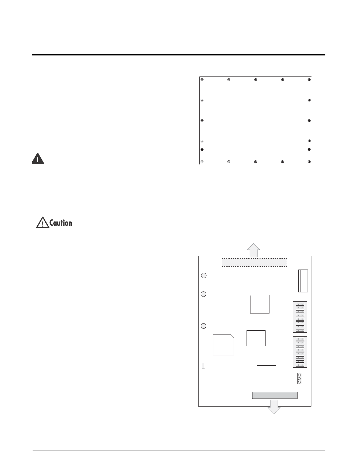
2.0 Installation
W arning
SW2
SW1
150Ω
82Ω
JMP4
1
1
P1
TP1
TP3
TP2
J2
1
Allen-Bradley Network
connections
J1
CPU board connection
1, 4 = BLUE
2, 5 = SHIELD
3, 6 = CLEAR
STATUS LED
123 4567 8123 4567 8
This section describes the procedures used to install
the Remote I/O interface card into the
920i indicators; connect communications cables;
and
520, 720i, 820i,
select the termination resistance; and set the
configuration DIP switches for the Remote I/O
interface.
2.1 Installing the Remote I/O Interface
Use the following procedure to install the Remote I/O
Interface card into
1. Disconnect indicator from power source.
2. Open indicator enclosure. For indicator
models with backplates, place indicator
face-down on an antistatic work mat and
remove screws that hold the backplate to the
enclosure body.
3. Carefully align the option card connector with
the option card slot on the indicator CPU
board (or
to seat the option card in the CPU board
connector.
4. Use the screws provided in the option kit to
secure the other end of
threaded standoffs on the CPU board.
5. Set termination resistance (jumper JMP4) as
described in
6. Wire the card to the network as described in
Section 2.1.2 on page 3.
7. Set DIP switches as described in Section 2.2
on page 4.
8. Use cable ties to secure loose cables inside the
enclos
For indicator models that include a backplate,
9.
position the backplate over the enclosure
reinstall the backplate screws. For the
and 920i desktop and universal m odels, use
the torque pattern shown in Figure 2-1 to
prevent distorting the backplate gasket.
Torque screws to 15 in-lb (1.7 N-m).
10. Ensure no excess cable is left inside the
enclosure a
2 Remote I/O Installation and Programming Manual
520, 720i, 820i, and 920i indicators.
Disconnect power before removing indicator
backplate. The 520, 720i, 820i, and 920i
have no on/off switch. Before opening the
unit, ensure the power cord is disconnected
from the power outlet.
Use a wrist strap to ground yourself and
protect components from elect
discharge (ESD) when working inside the
indicator enclosure.
920i expansion board). Press down
the option card to the
Section 2.1.1 on page 3.
ure.
nd tighten cord grips.
rostatic
and
820i
.
16 12
14
Torque backplate screws
to 15 in-lb (1.7 N-m)
5
3
1
17
9
Figure 2-1. 820i and 920i Enclosure Backplate.
8
7
10
11
11. Reconnect power to the indicator. The
indicator automatically recognizes all
installed option cards when the unit is
powered on. No hardware-specific
configuration is required to identify the
newly-installed Remote I/O card to the
system.
Figure 2-2. Remote I/O Interface Card
18
13
6
2
4
15
Page 7

2.1.1 Termination Resistance
If the Remote I/O Interface is the last, or only, device
attached to the PLC, the interface must provide a
termination resistance. Use Table 2-1 to determine the
appropriate termination resistance value and JMP4
jumper
position for the network. If the Remote I/O
Interface is not the last device in a chain, position the
jumper on one pin only. Resistance values for the
jumper positions are marked on the Remote I/O
Interface card.
JMP4
Network Data
Rate
57.6 Kbps 10 000 ft 16 150
115.2 Kbps 5000 ft
230.4 Kbps 2500 ft 32 82
Table 2-1. JMP4 Jumper Positions and Termination
Maximum
Cable Length
Resistance Values
Maximum
Nodes
Termination
Resistance
2.1.2 A-B Network Connections
Connections to the Allen-Bradley network are made at
connector J2 on the Remote I/O Interface card (see
Figure 2-2). Connectors 4–6 are tied to connectors
1–3 to allow daisy-chaining through the Remote I/O
Interface.
Feed Allen-Bradley network cable through cord grip.
Allow enou
gh cable for routing along inside of
enclosure to J2 connector on the Remote I/O Interface
card. Connect Allen-Bradley network cables into
connector J2 on the Remote I/O Interface card, then
use cable ties to secure network cables to the cable tie
mounts.
2.1.3 LED Status Indicator
A single LED on the Remote I/O card provides status
information for troubleshooting (see Figure 2-2).
Table 2-2 summarizes the function of the LED.
LED Function
OFF Not initialized or not receiving valid frames
Pulsing
(2Hz)
ON Valid communications established with
Communications established with Comm
1’
s or timeout
mmand 2’
Co
s
and
Table 2-2. Remote I/O Interface Status LED
Installation 3
Page 8
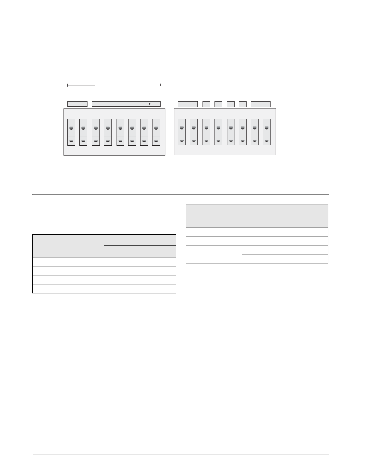
2.2 DIP Switch Configuration
SW2
SW1
Starting
Quarter
Rack Address
MSB
LSB
Network
Data Rate
Reserved
Last Rack
Rack Size
Reserved
Link Address
Block Transfer
12 345678
12 345678
OPEN
OPEN
Two banks of DIP switches, SW1 and SW2, are used to configure the Remote I/O Interface for communication
with the indicator and the network. Figure 2-3 shows the switch assignments for SW1 and SW2.
Figure 2-3. SW1 and SW2 DIP Switch Assignments.
Starting Quarter
Switches SW1-1 and SW1-2 set the starting quarter
(or group number) used by the Remote I/O Interface.
Use Table 2-3 to select the correct switch settings.
Starting
Quarter
1st 0 CLOSED CLOSED
2nd 2 OPEN CLOSED
3rd 4 CLOSED OPEN
4th 6 OPEN OPEN
Group
Number
Table 2-3. Starting Quarter
Rack Address
SW1 Switch Settings
1 2
Switches SW1-3 through SW1-8 are used to set the
rack address of the Remote I/O Interface. Use Table
on page 5 to select the correct switch settings for the
rack address.
logical “1” and that SW1-3 represents the least significant bit
(LSB) of the rack address.
Network Data Rate
Note that setting a switch OPEN acts as a
SW2-1 and SW2-2 set the data rate of the
Allen-Bradley network. Use Table 2-4 to select the
correct switch settings for the network.
SW2 Switch Settings
Remote I/O Data Rate
57.6 Kbps CLOSED CLOSED
115.2 Kbps OPEN CLOSED
230.4 Kbps CLOSED OPEN
1 2
OPEN OPEN
Table 2-4. Network Data Rate
Last Rack
Set SW2-3 OPEN if the Remote I/O Interface link
address includes the highest module group in this rack
address.
Rack Size
At this time only a quarter rack size is supported. This
option has been included for possible future expansion
to include half rack support. Switch 2-4 is ignored.
Block Transfer
Set SW2-6 CLOSED to enable or OPEN to disable
block transfer to the Remote I/O Interface. Setting this
switch OPEN causes the Remote I/O Interface to
ignore unsolicited block transfer requests from the
PLC.
4 Remote I/O Installation and Programming Manual
Page 9

Rack Address SW1 Switch Settings (LSB—>MSB) Rack Address SW1 Switch Settings (LSB—>MSB)
Decimal Octal 3 4 5 6 7 8 Decimal Octal 3 4 5 6 7 8
00 00 CLOSED CLOSED CLOSED CLOSED CLOSED CLOSED 32 40 CLOSED CLOSED CLOSED CLOSED CLOSED OPEN
01 01 OPEN CLOSED CLOSED CLOSED CLOSED CLOSED 33 41 OPEN CLOSED CLOSED CLOSED CLOSED OPEN
02 02 CLOSED OPEN CLOSED CLOSED CLOSED CLOSED 34 42 CLOSED OPEN CLOSED CLOSED CLOSED OPEN
03 03 OPEN OPEN CLOSED CLOSED CLOSED CLOSED 35 43 OPEN OPEN CLOSED CLOSED CLOSED OPEN
04 04 CLOSED CLOSED OPEN CLOSED CLOSED CLOSED 36 44 CLOSED CLOSED OPEN CLOSED CLOSED OPEN
05 05 OPEN CLOSED OPEN CLOSED CLOSED CLOSED 37 45 OPEN CLOSED OPEN CLOSED CLOSED OPEN
06 06 CLOSED OPEN OPEN CLOSED CLOSED CLOSED 38 46 CLOSED OPEN OPEN CLOSED CLOSED OPEN
07 07 OPEN OPEN OPEN CLOSED CLOSED CLOSED 39 47 OPEN OPEN OPEN CLOSED CLOSED OPEN
08 10 CLOSED CLOSED CLOSED OPEN CLOSED CLOSED 40 50 CLOSED CLOSED CLOSED OPEN CLOSED OPEN
09 11 OPEN CLOSED CLOSED OPEN CLOSED CLOSED 41 51 OPEN CLOSED CLOSED OPEN CLOSED OPEN
10 12 CLOSED OPEN CLOSED OPEN CLOSED CLOSED 42 52 CLOSED OPEN CLOSED OPEN CLOSED OPEN
11 13 OPEN OPEN CLOSED OPEN CLOSED CLOSED 43 53 OPEN OPEN CLOSED OPEN CLOSED OPEN
12 14 CLOSED CLOSED OPEN OPEN CLOSED CLOSED 44 54 CLOSED CLOSED OPEN OPEN CLOSED OPEN
13 15 OPEN CLOSED OPEN OPEN CLOSED CLOSED 45 55 OPEN CLOSED OPEN OPEN CLOSED OPEN
14 16 CLOSED OPEN OPEN OPEN CLOSED CLOSED 46 56 CLOSED OPEN OPEN OPEN CLOSED OPEN
15 17 OPEN OPEN OPEN OPEN CLOSED CLOSED 47 57 OPEN OPEN OPEN OPEN CLOSED OPEN
16 20 CLOSED CLOSED CLOSED CLOSED OPEN CLOSED 48 60 CLOSED CLOSED CLOSED CLOSED OPEN OPEN
17 21 OPEN CLOSED CLOSED CLOSED OPEN CLOSED 49 61 OPEN CLOSED CLOSED CLOSED OPEN OPEN
18 22 CLOSED OPEN CLOSED CLOSED OPEN CLOSED 50 62 CLOSED OPEN CLOSED CLOSED OPEN OPEN
19 23 OPEN OPEN CLOSED CLOSED OPEN CLOSED 51 63 OPEN OPEN CLOSED CLOSED OPEN OPEN
20 24 CLOSED CLOSED OPEN CLOSED OPEN CLOSED 52 64 CLOSED CLOSED OPEN CLOSED OPEN OPEN
21 25 OPEN CLOSED OPEN CLOSED OPEN CLOSED 53 65 OPEN CLOSED OPEN CLOSED OPEN OPEN
22 26 CLOSED OPEN OPEN CLOSED OPEN CLOSED 54 66 CLOSED OPEN OPEN CLOSED OPEN OPEN
23 27 OPEN OPEN OPEN CLOSED OPEN CLOSED 55 67 OPEN OPEN OPEN CLOSED OPEN OPEN
24 30 CLOSED CLOSED CLOSED OPEN OPEN CLOSED 56 70 CLOSED CLOSED CLOSED OPEN OPEN OPEN
25 31 OPEN CLOSED CLOSED OPEN OPEN CLOSED 57 71 OPEN CLOSED CLOSED OPEN OPEN OPEN
26 32 CLOSED OPEN CLOSED OPEN OPEN CLOSED 58 72 CLOSED OPEN CLOSED OPEN OPEN OPEN
27 33 OPEN OPEN CLOSED OPEN OPEN CLOSED 59 73 OPEN OPEN CLOSED OPEN OPEN OPEN
28 34 CLOSED CLOSED OPEN OPEN OPEN CLOSED 60 74 CLOSED CLOSED OPEN OPEN OPEN OPEN
29 35 OPEN CLOSED OPEN OPEN OPEN CLOSED 61 75 OPEN CLOSED OPEN OPEN OPEN OPEN
30 36 CLOSED OPEN OPEN OPEN OPEN CLOSED 62 76 CLOSED OPEN OPEN OPEN OPEN OPEN
31 37 OPEN OPEN OPEN OPEN OPEN CLOSED 63 77 OPEN OPEN OPEN OPEN OPEN OPEN
Table 2-5. SW1 Switch Settings for Remote I/O Interface Rack Address
2.3 Decimal Point Handling
Discrete Transfer
Discrete transfer commands return no decimal point information to the PLC. For example, a value of 750.1
displayed on the indicator is returned to the PLC as 7501.
Block Transfer
Block transfer commands support decimal point information with no special handling.
Installation 5
Page 10

3.0 Discrete Transfer Commands
Discrete commands are used by the PLC to send and receive data from the Remote I/O Interface. The PLC
controller and Remote I/O Interface share a quarter rack of slot space, resulting in two 16-bit words for the output
image table (used to write commands to the indicator) and two 16-bit words for the input image table (used to
read data from the indicator).
NOTE: Data returned by discrete transfer commands is not valid when the indicator is in setup mode.
3.1 Output Image Table Format
To perform a discrete command, the PLC places two 16-bit words in the PLC output image table, which is sent
by the scanner to the node adapter of the Remote I/O Interface. The Remote I/O Interface provides the contents
of the output image table to the indicator for command processing.
The format of the output image table is shown in Table 3-1.
Bit 15 14 13 12 11 10 9 8 7 6 5 4 3 2 1 0
Word 0 v15 v14 v13 v12 v11 v10 v09 v08 v07 v06 v05 v04 v03 v02 v01 v00
Word 1 p07 p06 p05 p04 p03 p02 p01 p00 c07 c06 c05 c04 c03 c02 c01 c00
Table 3-1. Output Image Table Format
where:
v00–v15 16-bit unsigned integer value
p00–p07 Parameter value
c00–c07 Command number
These fields are described below:
Val ue
Word 0 of the output image table is used to pass value
data on certain commands. This field should be used
only when block transfer is disabled. For example, to
enter a tare value, use word 0 to specify the tare value;
the Enter Tare command number (12) is specified in
bits 00 through 07 of word 1.
Values entered in this field are
treated as
unsigned
integers. Possible values range from 0 to 65535.
Decimal Hex Binary Command
0 0x00 0000 0000 Return Status and Weight
1 0x01 0000 0001 Display Channel
2 0x02 0000 0010 Display Gross Weight
3 0x03 0000 0011 Display Net Weight
4 0x04 0000 0100 Display Piece Count
9 0x09 0000 1001 Gross/Net key press (tog
10 0x0A 000
11 0x0B 0000 1011 Display Tare
12 0x0C 0000 1100 Enter Tare (integer)
13 0x0D 0000 1101 Acquire Tare
0 1010 Zero
Parameter value
To allow communication with a multi-scale indicator,
the scale number is sent in the upper byte of word 1. A
value of 0 represents the current scale. Certain
commands require a parameter other than a scale
number. These commands are noted in the table as
requiring a slot number or other selection parameter.
Command Number
The number representing the indicator command is
sent in the lower byte of word 1. Table 3-2 lists the
remote commands that can be specified for
920i indicators on discrete write commands.
NOTE: A lockout feature that looks for any change in the
image table data is incorporated into the indicator receive
mechanism to prevent inundation by the same command.
Repeated commands must be separated by any other valid
command/parameter/value combination.
gle mode)
520 and
Table 3-2. 520 /720i/ 820i / 920i Remote Commands
6 Remote I/O Installation and Programming Manual
Page 11

Decimal Hex Binary Command
14 0x0E 0000 1110 Clear Tare
16 0x10 0001 0000 Primary Units
17 0x11 0001 0001 Secondary Units
18 0x12 0001 0010 Tertiary Units
19 0x13 0001 0011 Units key press (toggle units)
20 0x14 0001 0100 Print Request
21 0x15 0001 0101 Display Accumulator
22 0x16 0001 0110 Clear Accumulator
23 0x17 0001 0111 Push Weight to Accumulator
32 0x20 0010 0000 Return Gross (integer)
33 0x21 0010 0001 Return Net (integer)
34 0x22 0010 0010 Return Tare (integer)
35 0x23 0010 0011 Return Piece Count
37 0x25 0010 0101 Return Current Display (integer)
38 0x26 0010 0110 Return Accumulator (integer)
39 0x27 0010 0111 Return Rate of Change (integer)
40 0x28 0010 1000 Return Peak (integer)
95 0x5F 0101 1111 Set Batching State
96 0x60 0110 0000 Batch Start
97 0x61 0110 0001 Batch Pause
98 0x62 0110 0010 Batch Reset
99 0x63 0110 0011 Batch Status
112 0x70 0110 0100 Lock Indicator Front Panel
113 0x71 0110 0101 Unlock Indicator Front Panel
114 0x72 0110 0110 Set Digital Input ON
115 0x73 0110 0111 Set Digital Input OFF
116 0x74 0110 1000 Read Digital Input Status
253 0xFD 1111 1101 No operation
254 0xFE 1111 1110 Reset Indicator
368 0x170 10111 0000 Set Register
402 0x192 11001 0010
Get Register
Table 3-2. 520 /720i/ 820i / 920i Remote Commands (Continued)
Discrete Transfer Commands 7
Page 12

3.2 Input Image Table Format
In response to a discrete command, the Remote I/O Interface interface returns data and status information across
the network as two 16-bit words. This information is read from the input image table by the PLC. The format of
the input image table is shown in Table 3-3:
Bit 15 14 13 12 11 10 9 8 7 6 5 4 3 2 1 0
Word 0 v15 v14 v13 v12 v11 v10 v09 v08 v07 v06 v05 v04 v03 v02 v01 v00
Word 1 s11 s10 s09 s08 s07 s06 s05 s04 s03 s02 s01 s00 v19 v18 v17 v16
Table 3-3. Input Image Table Format
where:
v00–v19 20-bit unsigned integer
s00–s11 Status data
Val ue
Weight data is returned to the PLC using word 0 and
bits 0 to 3 from word 1 of the input image table. The
PLC can use just word 0 to read data in a 16-bit
format, allowing unsigned values from 0 to 65,535 to
be returned from the indicator. If larger numbers or
greater precision is required, the PLC can piece
together the additional four bits from word 1, resulting
in a 20-bit unsigned value. This format allows the
indicator to return values up to 1,048,575. Polarity is
returned with status data. The weight data returned is
the displayed weight after the command is executed
unless the command specifies otherwise.
Status Data
Indicator status data is returned in bits 4–15 of word 1.
Status data is listed in Table 3-4. Batch commands
return batch status in place of bits 8–15 as listed in
Table 3-5.
Channel Bits
Bits s01–s03 of the indicator status data (Table 3-4)
are used to represent the lower three bits of the scale
channel number. For example, if a value of ‘001’ is
returned in these bits, the scale channel number is 1, 9,
17 or 25.
Word 1
Status
Bit
04 s00 Positive weight Negative weight
05 s01 Lower three bits of scale number
06 s02
07 s03
08 s04 Gross Net
09 s05 No tare Tare acquired
10 s06 Primary units Secondary/ other
11 s07 Standstill In motion
12 s08 Weight invalid /
13 s09 Not zero Center of zero
14 s10 Tare not entered Tare entered
15 s11 Error No error
Bit
Table 3-4. Indicator Status Data Format
Word 1
Status
Bit
08 s04 Alarm OFF Alarm ON
09 s05 Batch not stopped Batch stopped
10 s06 Batch not running Batch running
11 s07 Batch not paused Batch paused
12 s08 Digital input 1 OFF Digital input 1 ON
13 s09 Digital input 2 OFF Digital input 2 ON
14 s10 Digital input 3 OFF Digital input 3 ON
15 s11 Digital input 4 OFF
Bit
Indicator Status Data
Value=0 Value=1
uni
We
ight OK
-range
Over
Batch Function Status Data
Value=0 Value=1
Digital input 4 ON
520) Error
(
(520) No error
s
t
8 Remote I/O Installation and Programming Manual
Table 3-5. Batch Function Status Data Format
Page 13

3.3 Discrete Command Descriptions
NOTE: For all commands that require a scale number, a value
of 0 indicates the current scale. Unless otherwise specified,
the indicator returns weight and status data for the specified
scale.
Return Status and Current Weight
Command: 0, 0x00
Parameter: Scale number
Command 0 returns the status and weight of the
specified scale in integer format, without changing the
display.
Display Channel
Command: 1, 0x01
Parameter: Scale number
Command 1 causes the weight of the specified scale to
be displayed and returned in its current mode and
format. This command is valid for the
Display Gross Weight
Command: 2, 0x02
Parameter: Scale number
Command 2 causes the gross weight of the specified
scale to be displayed and returned.
Display Net Weight
Command: 3, 0x03
Parameter: Scale number
Command 3 causes the net weight of the specified
scale to be displayed and returned.
Display Piece Count
Command: 4, 0x04
Parameter: Scale number
Command 4 causes the piece count on the specified
scale to be displayed and returned. This command is
valid only for the
520 indicator, and only if count
mode is enabled.
Gross/Net Key Press (toggle mode)
Command: 9, 0x09
Parameter: Scale number
Command 9 toggles between gross and net mode (and
count mode, if enabled). If a scale number other than 0
is specified, the action may not be evident until the
specified scale is displayed.
Zero
Command: 10, 0x0A
Command 10 performs a zero action on the current
scale.
920i only.
Display Tare
Command: 11, 0x0B
Parameter: Scale number
Command 11 causes the tare weight on the specified
scale to be displayed. If a scale number other than 0 is
specified, the indicator first causes the specified scale
to be displayed. The tare data continues being
returned even if the display times out and returns to
another mode, until another command is issued.
Enter Tare (integer)
Command: 12, 0x0C
Parameter: Scale number
Value: Tare weight
Command 12 enters a tare for the scale selected. Tare
data must be in integer format. The indicator
continues to return weight data in the current mode for
the specified scale. This command is not valid if block
transfer is enabled.
Acquire Tare (simulate tare key press)
Command: 13, 0x0D
Parameter: Scale number
Command 13 acquires a tare based on the weight
currently on the specified scale. The indicator
continues to return weight data in the current mode for
the specified scale.
Clear Tare
Command: 14, 0x0E
Parameter: Scale number
Command 14 clears the tare for the specified scale.
The indicator continues to return weight data in the
current mode for the specified scale.
Primary Units
Command: 16, 0x10
Parameter: Scale number
Command 16 switches the current format of the
specified scale to the primary units configured for that
scale.
Secondary Units
Command: 17, 0x11
Parameter: Scale number
Command 17 switches the current format of the
specified scale to the secondary units configured for
that scale.
Tertiary Units
Command: 18, 0x12
Parameter: Scale number
Command 18 switches the current format of the
specified scale to the tertiary units configured for that
scale. This command is valid for the
920i only.
Discrete Transfer Commands 9
Page 14

Units Key Press (toggle units)
Command: 19, 0x13
Parameter: Scale number
Command 19 toggles the current format of the
specified scale to the next units configured for that
scale, as available.
Return Piece Count
Command: 35, 0x23
Parameter: Scale number
Command 35 returns the piece count value for the
specified scale. This command is valid only for the
520 indicator, and only if count mode is enabled.
Print Request
Command: 20, 0x14
Parameter: Scale number
Command 20 causes the indicator to execute a print
request using the current scale.
Display Accumulator
Command: 21, 0x15
Parameter: Scale number
Command 21 causes the value of the accumulator for
the specified scale to be displayed and returned. This
command is only valid if the accumulator for the
specified scale is enabled.
Clear Accumulator
Command: 22, 0x16
Parameter: Scale number
Command 22 clears the value of the accumulator for
the specified scale. This command is only valid if the
accumulator for the specified scale is enabled.
Push Weight to Accumulator
Command: 23, 0x17
Parameter: Scale number
Command 23 adds the net weight on the specified
scale to the value of the accumulator for the specified
scale. The scale must return to net zero between
accumulations. The indicator returns the accumulated
weight data for the specified scale. This command is
only valid if the accumulator for the specified scale is
enabled.
Return Gross as Integer
Command: 32, 0x20
Parameter: Scale number
Command 32 returns the gross weight value for the
specified scale as an integer.
Return Current Display as Integer
Command: 37, 0x25
Parameter: Scale number
Command 37 returns the weight value for the
specified scale as currently displayed. This may
include gross, net, tare, piece count, or accumulator
values, as enabled. On the
920i, the weight value is
returned in the mode used to display a scale widget.
Return Accumulator as Integer
Command: 38, 0x26
Parameter: Scale number
Command 38 returns the accumulator value for the
specified scale. This command is only valid if the
accumulator for the specified scale is enabled.
Return Rate of Change as Integer
Command: 39, 0x27
Parameter: Scale number
Command 39 returns the current rate of change value
for the specified scale. This command is valid only for
720i, 820i, 920i.
the
Return Peak as Integer
Command: 40, 0x28
Parameter: Scale number
Command 40 returns the net peak value for the
specified scale. This command is valid only for the
520 indicator, and only if the peak hold function is
enabled.
Set Batching State
Command: 95, 0x5F
Parameter: State (0 = off; 1 = auto; 2 = manual)
Command 95 sets the batching (BATCHNG)
parameter. Indicator status is returned with the current
weight for the last scale specified.
Return Net as Integer
Command: 33, 0x21
Parameter: Scale number
Command 33 returns the net weight value for the
specified scale as an integer.
Return Tare as Integer
Command: 34, 0x22
Parameter: Scale number
Command 34 returns the tare weight value for the
specified scale as an integer.
10 Remote I/O Installation and Programming Manual
Batch Start
Command: 96, 0x60
Parameter: Scale number
Command 96 starts a batch program from the current
step after a stop, pause or reset. Batch status is
returned with the current weight for the specified
scale.
Page 15

Batch Pause
Command: 97, 0x61
Parameter: Scale number
Command 97 pauses a batch program at the current
step. Batch status is returned with the current weight
for the specified scale.
Batch Reset
Command: 98, 0x62
Parameter: Scale number
Command 98 stops a batch program and resets it to
the first batch step. Batch status is returned with the
current weight for the specified scale.
Batch Status
Command: 99, 0x63
Parameter: Scale number
Command 99 returns the status of a batch. Batch
status is returned with the current weight for the
specified scale.
Lock Front Panel of Indicator
Command: 112, 0x70
Parameter: Scale number
Command 112 disables all the keys on the front panel
of the indicator. Indicator status is returned with the
current weight for the specified scale.
Unlock Front Panel of Indicator
Command: 113, 0x71
Parameter: Scale number
Command 113 re-enables all the keys on the front
panel of the indicator. Indicator status is returned with
the current weight for the specified scale.
Set Digital Output ON
Command: 114, 0x72
Parameter: Slot number
Val ue : Bit n umber
Command 114 sets the specified digital output ON
(active). Use slot number 0 for onboard digital
outputs. Indicator status is returned with the current
weight for the last scale specified. This command is
not valid if block transfer is enabled.
Read Digital I/O
Command: 116, 0x74
Parameter: Slot Number and Shift (1 = low; 2 = high)
Command 116 returns the status of all digital I/O
(digital inputs only, for the
520) for the slot specified
in word 0.
Because word 0 only contains 16 bits,
a shift is used to
slide a "window" over the slot data to be returned. The
high nibble of the parameter contains 1 to look at the
low 16 bits of the slot (bits 1–16) or 2 to return the
high 16 bits (bits 9–24). Use slot number 0 for
onboard digital inputs. Indicator status is returned in
the status area for the last scale specified.
No Operation
Command: 253, 0xFD
Parameter: Scale number
Command 253 provides a command to use between
operations, as necessary, without causing the indicator
to perform any action. Indicator status and weight data
for the specified scale is still returned.
Reset Indicator
Command: 254, 0xFE
Parameter: None
Command 254 provides a command to remotely reset
the indicator. No data is returned.
Set Register
Command: 368
Registers: 1 thru 256
Command 368 sets register value. 1 through128 are
integer and 129 through 256 are real. This command
is only valid for the
Get Register
Command: 402
Registers: 1 thru 256
720i PCE version.
Command 402 returns register value. 1 through128
are integer and 129 through 256 are real. This
command is only valid for the
720i PCE version.
Set Digital Output OFF
Command: 115, 0x73
Parameter: Slot number
Val ue : Bit n umber
Command 115 sets the specified digital output OFF
(inactive). Use slot number 0 for onboard digital
outputs. Indicator status is returned with the current
weight for the last scale specified. This command is
not valid if block transfer is enabled.
Discrete Transfer Commands 11
Page 16

4.0 Block Transfer Commands
The Remote I/O Interface supports block transfer commands for the 520, 720i, 820i, and 920i indicators. These
commands allow the PLC controller to exchange larger blocks of data with the indicator, such as 32-bit
floating-point values and partial setpoint configuration.
NOTE: Weight data returned by block transfer commands is not valid when the indicator is in setup mode.
Table 4-1 shows the block write and block read commands supported by the Remote I/O Interface.
Command Number
Command Name
268 0x10C Set Tare Value 4 4
288 0x120 Read Gross Weight 2 4
289 0x121 Read Net Weight 2 4
290 0x122 Read Tare Weight 2 4
291 0x123 Read Piece Count 2 4
293 0x125 Read Current Display 2 4
294 0x126 Read Accumulator 2 4
295 0x127 Read Rate of Change 2 4
296 0x128 Read Peak Value 2 4
302 0x12E Read Gross, Tare, Net 2 8
303 0x12F Read Multiple Weights 4 4–62
304 0x130 Set Setpoint Value 4 2
305 0x131 Set Setpoint Hysteresis 4 2
306 0x132 Set Setpoint Bandwidth 4 2
307 0x133 Set Setpoint Preact 4 2
319 0x13F Set Single Setpoint, All Values 10 2
320 0x140 Read Setpoint Value 2 4
321 0x141 Read Setpoint Hysteresis 2 4
322 0x142 Read Setpoint Bandwidth 2 4
323 0x143 Read Setpoint Preact 2 4
335 0x14F Read Single Setpoint, All Values 2 10
336 0x150 Set Multiple Setpoint Values 4–62 2
337 0x151 Read Multiple Setpoint Values 2 4–62
and lengths expressed as number of words. Number of words required for variable length commands depends on
NOTE: Com
number of setpoints or scales specified.
m
Block Write
Command
Length
Block Read
Command
LengthDecimal Hex
Table 4-1. Block Transfer Commands
12 Remote I/O Installation and Programming Manual
Page 17

4.1 Block Write Command Format
The format for sending a block write command includes a minimum of two words. The first word always
contains the command to be executed by the indicator. The second word contains one or more parameters
necessary to execute the command, such as a scale number or setpoint number. If a command requires additional
values, this data follows, generally as one or more 4-byte, single-precision floating-point numbers. Below is a
general outline and example for setting up a data file for a block write command.
Word Description Sample Data Description
0 Command number (hex) 0x010C Set Tare command
1 Parameter data (hex) 0x0000 Current scale
2 Value, MSW 125.0 Ta r e v a l u e
3 Val ue , LSW
Table 4-2. Block Write Command Format Example
4.2 Block Read Command Format
Block read commands have a similar format. The first word echoes the command number. If the command fails
or is not recognized, the negative of the command number is returned to signal the error. The second word
contains a status of the indicator for the scale selected , or a batch status for setpoint commands. Data being
returned to the PLC follows, as required by the command, generally as one or more 4-byte, single-precision
floating-point numbers. Below is a general outline and example for setting up a data file for a block read
command.
Word Description Sample Data Description
0 Command number 0x0151 Read Multiple Setpoints command
1 Status data 0x0B02 Batch status
2 First value, MSW 150.0 Setpoint 1 value
3 First value, LSW
4 Second value, MSW 225.0 Setpoint 2 value
5 Second value, LSW
Table 4-3. Block Read Command Format Example
Block Transfer Commands 13
Page 18

Status Data
Block command status bit definitions are shown in
Table 4-4. Setpoint commands return the setpoint
ber in the low byte, batch status in the high byte
num
of the status word (see Table 4-5).
Word 1
Status
Bit
00 s00 Positive weight Negative weight
01 s01 Reserved
02 s02
03 s03 Scale number
04 s04
05 s05
06 s06
07 s07
08 s08 Gross Net
09 s09 No tare Tare acqu i red
10 s10 Primary units Secondary/ other
11 s11 Standstill In motion
12 s12 Weight invalid /
13 s13 Not zero Center of zero
14 s14 Tare not entered Tare entered
15 s15 Error No error
Bit
(NOTE: Value 0 represents scale #32)
Indicator Status Data
Val ue =0 Va lue=1
un
Weight OK
-range
Over
i
ts
Word 1
00 s00 Setpoint number
01 s01
02 s02
03 s03
04 s04
05 s05
06 s06
07 s07
08 s08 Alarm OFF Alarm ON
09 s09 Batch not stopped Batch stopped
10 s10 Batch not running Batch running
11 s11 Batch not paused Batch paused
12 s12 Digital input 1 OFF Digital input 1 ON
13 s13 Digital input 2 OFF Digital input 2 ON
14 s14 Digital input 3 OFF Digital input 3 ON
15 s15 Digital input 4 OFF
Bit
Status
Bit
Batch Function Status Data
Value=0 Value=1
Digital input 4 ON
520) Error
(
(520) No error
Table 4-5. Batch Function Status Data Format
Table 4-4. Block Command Status Data Format
14 Remote I/O Installation and Programming Manual
Page 19

4.3 Block Transfer Command Descriptions
NOTE: For all commands that require a scale number, a value
of 0 indicates the current scale. Unless otherwise specified,
the indicator returns weight and status data for the specified
scale.
Set Tare Value
Command: 268, 0x10C
Block Write: 4 words
Parameter: Scale number
Value: Tare weight
Block Read: 4 words
Return Status: Selected scale
Return Value: Tare weight
Command 268 enters a tare for the scale selected in
floating-point format. The indicator returns the tare
weight as taken, or 0 for no tare.
Read Gross Weight
Command: 288, 0x120
Block Write: 2 words
Parameter: Scale number
Val ue : None
Block Read: 4 words
Return Status: Selected scale
Return Value: Gross weight
Command 288 returns the gross weight value for the
specified scale in floating-point format.
Read Net Weight
Command: 289, 0x121
Block Write: 2 words
Parameter: Scale number
Val ue : None
Block Read: 4 words
Return Status: Selected scale
Return Value: Net weight
Command 289 returns the net weight value for the
specified scale in floating-point format.
Read Tare Weight
Command: 290, 0x122
Block Write: 2 words
Parameter: Scale number
Val ue : None
Block Read: 4 words
Return Status: Selected scale
Return Value: Tare weight
Command 290 returns the tare weight value for the
specified scale in floating-point format.
Read Piece Count
Command: 291, 0x123
Block Write: 2 words
Parameter: Scale number
Value: None
Block Read: 4 words
Return Status: Selected scale
Return Value: Count value
Command 291 returns the piece count value for the
specified scale in floating-point format. This
command is only valid for the
520, and only if count
mode is enabled.
Read Current Display
Command: 293, 0x125
Block Write: 2 words
Parameter: Scale number
Value: None
Block Read: 4 words
Return Status: Selected scale
Return Value: Currently displayed
weight
Command 293 returns the weight value for the
specified scale as currently displayed in floating-point
format. This may include gross, net, tare, piece count,
or accumulator values, as enabled. On the
920i, the
weight value is returned in the mode used to display a
scale widget.
Read Accumulator
Command: 294, 0x126
Block Write: 2 words
Parameter: Scale number
Value: None
Block Read: 4 words
Return Status: Selected scale
Return Value: Accumulator value
Command 294 returns the accumulator value for the
specified scale in floating-point format. This
command is only valid if the accumulator for the
specified scale is enabled.
Read Rate of Change
Command: 295, 0x127
Block Write: 2 words
Parameter: Scale number
Value: None
Block Read: 4 words
Return Status: Selected scale
Return Value: Rate of change value
Command 295 returns the current rate of change value
for the specified scale in floating-point format. This
command is only valid for the
920i.
Block Transfer Commands 15
Page 20

Read Peak Value
Command: 296, 0x128
Block Write: 2 words
Parameter: Scale number
Val ue : None
Block Read: 4 words
Return Status: Selected scale
Return Value: Net peak weight
Command 296 returns the net peak value for the
specified scale in floating-point format. This
command is only valid for the
520, and only if the
peak hold function is enabled.
Set Setpoint Value
Command: 304, 0x130
Block Write: 4 words
Parameter: Setpoint number
Value: Target Value
Block Read: 2 words
Return Status: Batch
Return Value: None
Command 304 sets the target value for the specified
setpoint in floating-point format. This command is
only valid if the setpoint is enabled and requires a
target value.
Read Gross, Tare, Net
Command: 302, 0x12E
Block Write: 2 words
Parameter: Scale number
Val ue : None
Block Read: 8 words
Return Status: Selected scale
Return Value: Gross, tare, and net
weights
Command 302 returns the gross, tare, and net weights
on a single command. The structure of the command
is as follows:
Word 0: Command number
Word 1: Scale number
Words 2–3: Gross weight
Words 4–5: Tare weight
Words 6–7: Net weight
Read Multiple Weights
Command: 303, 0x12F
Block Write: 4 words
Parameter: Weight type
Value: Bit-map of scales
Block Read: Variable, 4 words minimum
Return Status: Composite
Return Value: Weight for each scale
re
quested
Command 303 returns the weights for up to 30 scales
in floating-point format. The weights are returned in
the mode specified by the parameter weight type, 0 for
gross or 1 for net. Words 2 and 3 contain a bit map of
the scales for which a weight should be returned; the
least significant bit represents scale 1. Each 2-word
value represents the weight for the next scale
requested, if valid, beginning with scale 1. If a scale is
not valid (scale does not exist), the bit is ignored.
Status data returned is a composite of the scales
requested, according to the following rules:
• Indicator status: If a bit is set for any of the
scales requested, it is set in the composite.
• Scale number: The total number of scales in
the composite is returned.
This command is valid only for
820i or 920i.
Set Setpoint Hysteresis
Command: 305, 0x131
Block Write: 4 words
Parameter: Setpoint number
Value: Hysteresis value
Block Read: 2 words
Return Status: Batch
Return Value: None
Command 305 sets the hysteresis va lue for the
specified setpoint in floating-point format. This
command is only valid if the setpoint is enabled and
requires a hysteresis value.
Set Setpoint Bandwidth
Command: 306, 0x132
Block Write: 4 words
Parameter: Setpoint number
Value: Bandwidth value
Block Read: 2 words
Return Status: Batch
Return Value: None
Command 306 sets the bandwidth value for the
specified setpoint in floating-point format. This
command is only valid if the setpoint is enabled and
requires a bandwidth value.
Set Setpoint Preact
Command: 307, 0x133
Block Write: 4 words
Parameter: Setpoint number
Value: Preact Value
Block Read: 2 words
Return Status: Batch
Return Value: None
Command 307 sets the preact value for the specified
setpoint in floating-point format. This command is
only valid if the setpoint is enabled and requires a
preact value.
16 Remote I/O Installation and Programming Manual
Page 21

Set Single Setpoint, All Values
Command: 319, 0x13F
Block Write: 10 words
Parameter: Setpoint number
Value: Values as required
Block Read: 2 words
Return Status: Batch
Return Value: None
Command 319 sets the target, hysteresis/bandwidth
and preact values for the specified setpoint in
floating-point format. This command is only valid if
the setpoint is enabled and requires a target value.
The structure of the block write command is as
follows:
Word 0: Command number
Word 1: Setpoint number
Word 2: Setpoint kind
Word 3: Re
Words 4–5: Target value
Words 6–7: Hysteresis or band value
Words 8–9: Preact value
served/not used
The value sent in words 6 and 7 is interpreted as
hysteresis or band value based on the TRIP setting of
the setpoint. If the setpoint requires neither a
hysteresis nor a band value, this value is ignored and
only the target value is set. The preact value is ignored
if preact is not enabled for the setpoint.
Table 4-6 lists the values specified for the setpoint
kind in word 2.
Supported for
Indicator
820i/
Value (Hex) Setpoint Kind
0000 OFF
0001 GROSS
0002 NET
0003 –GROSS (Negative gross)
0004 –NET (Negative net)
0005 ACCUM (Accumulator)
0006 ROC (Rate of change)
0007 +REL (Positive relative)
0008 –REL (Negative relative)
0009 %REL (Percent relative)
000A RESREL (Result relative)
000B PAU SE
000C DELAY
000D WAITSS (Wait for standstill)
000E COUNTER
520
920i
Supported for
Indicator
820i/
Value (Hex) Setpoint Kind
000F AUTOJOG
0010 COZ (Center of zero)
0011 INMOTON (In motion)
0012 INRANGE (In range)
0013 BATCHPR (Batch process)
0014 TIMER
0015 CONCUR
0016 DIGIN (Digital input)
0017 AVG (Average)
0018 TOD (Time of day)
0019 DELTA (Delta weight)
001A CHKWEI (Checkweigher)
001B PLSCNT (Pulse counter)
001C PLSRAT (Pulse rate)
001D ALWAYS
001E NEVER
520
920i
Table 4-6. T able nt Kind Values (Continued)
Read Setpoint Value
Command: 320, 0x140
Block Write: 2 words
Parameter: Setpoint number
Value: None
Block Read: 4 words
Return Status: Batch
Return Value: Target value
Command 320 returns the target value for the
specified setpoint in floating-point format. This
command is only valid if the setpoint is enabled and
requires a target value.
Read Setpoint Hysteresis
Command: 321, 0x141
Block Write: 2 words
Parameter: Setpoint number
Value: None
Block Read: 4 words
Return Status: Batch
Return Value: Hysteresis value
Command 321 returns the hysteresis value for the
specified setpoint in floating-point format. This
command is only valid if the setpoint is enabled and
requires a hysteresis value.
Table 4-6. Table nt Kind Values
Block Transfer Commands 17
Page 22

Read Setpoint Bandwidth
Command: 322, 0x142
Block Write: 2 words
Parameter: Setpoint number
Val ue : None
Block Read: 4 words
Return Status: Batch
Return Value: Bandwidth value
Command 322 returns the bandwidth value for the
specified setpoint in floating-point format. This
command is only valid if the setpoint is enabled and
requires a bandwidth value.
Read Setpoint Preact
Command: 323, 0x143
Block Write: 2 words
Parameter: Setpoint number
Val ue : None
Block Read: 4 words
Return Status: Batch
Return Value: Preact value
Command 323 returns the preact value for the
specified setpoint in floating-point format. This
command is only valid if the setpoint is enabled and
requires a preact value.
Read Single Setpoint, All Values
Command: 335, 0x14F
Block Write: 2 words
Parameter: Setpoint number
Val ue : None
Block Read: 10 words
Return Status: Batch
Return Value: Values as available
Command 335 returns the target,
hysteresis/bandwidth and preact values for the
specified setpoint in floating-point format. This
command is only valid if the setpoint is enabled and
requires a target value.
The structure of the block read command is as
follows:
Word 0: Command number
Word 1: Setpoint number
Word 2: Setpoint kind
Word 3: Reser
Words 4–5: Target value
Words 6–7: Hysteresis or band value
Words 8–9: Preact value
ved/not used
The value returned in words 6 and 7 is either the
hysteresis or band value, based on the TRIP setting of
the setpoint. If the setpoint requires neither a
hysteresis nor a band value, this value is set to 0. The
preact value returned is set to 0 if preact is not enabled
for the setpoint.
See Table 4-6 for a list of the setpoint kind valu es
returned in word 2.
Set Multiple Setpoint Values
Command: 336, 0x150
Block Write: Variable, 4 words minimum
Parameter: Setpoint range
Value: Values as required
Block Read: 2 words
Return Status: Batch
Return Value: None
Command 336 sets the target values for the specified
range of setpoints in floating-point format. The first
value sent is the target value for the setpoint number
specified in the low byte of the parameter. The last
value sent is the target value for the setpoint number
specified in the high byte of the parameter. If a target
value is not required for any setpoint, the value should
be set to 0.0, but is actually ignored by the indicator.
Up to 30 setpoints can be set at one time. The return
status includes the setpoint number of the last setpoint
set.
Read Multiple Setpoint Values
Command: 337, 0x151
Block Write: 2 words
Parameter: Setpoint range
Value: None
Block Read: Variable, 4 words minimum
Return Status: Batch
Return Value: Values as available
Command 337 returns the target values for the
specified range of setpoints in floating-point format.
The first value returned is the target value for the
setpoint number specified in the low byte of the
parameter. The last value returned is the target value
for the setpoint number specified in the high byte of
the parameter. If a target value is not required for any
setpoint, the value returned is 0.0. Up to 30 setpoints
can be requested at one time. The return status
includes the setpoint number of the last setpoint read.
18 Remote I/O Installation and Programming Manual
Page 23

5.0 Operation
The examples on the following pages provide PLC programming examples for using the Remote I/O Interface.
5.1 Test Program for Verifying Remote I/O Interface Operation
The programming example shown on the next page writes a series of dis crete commands to the Remote I/O
Interface and checks the status bits returned in the input image table to confirm completion of each command.
This example assumes the Remote I/O scanner to be in slot #2, with the Remote I/O Interface at rack address 0,
quarter 0.
NOTES:
• This program can be edited and used to test communic
• The COMMAND WORD must be zeroed after chec
ations between the PLC and the Remote I/O Interface.
king the status bits to confirm that the command has been executed.
Operation 19
Page 24

MOV
MOV
COMMAND WORD
COMMAND WORD
MOV
COMMAND WORD
MOV
COMMAND WORD
MOV
COMMAND WORD
S2:1
B3
0
15
B3
B3
B3
1
2
3
0
1
2
3
4
5
MOV
COMMAND WORD
JSR
Jump To Subroutine
SBR File Number U:8
CONVERT
6
7
[END]
B3
0
(U)
B3
1
(U)
B3
2
(U)
B3
3
(U)
TARE SCALE
DISPLAY
GROSS WEIGHT
DISPLAY
NET WEIGHT
CLEAR TARE
B3
0
I:2.1
6
B3
1
I:2.1
7
B3
2
I:2.1
7
B3
3
I:2.1
6
TARE SCALE SCALE TARE STATUS
DISPLAY
GROSS WEIGHT
GROSS/NET
STATUS
DISPLAY
NET WEIGHT
GROSS/NET
STATUS
CLEAR TARE
SCALE TARE
STATUS
MONITOR STATUS BITS TO CONFIRM EACH TASK IS PERFORMED,
THEN CLEAR DISCRETE WRITE OUTPUT
CLEAR DISCRETE WRITE OUTPUT COMMAND
IF TARE BIT IS SET, SEND ACQUIRE TARE COMMAND TO DISCRETE WRITE OUTPUT
TARE SCALE
DISPLAY GROSS WEIGHT
DISPLAY NET WEIGHT
CLEAR TARE
IF GROSS BIT IS SET, SET SCALE TO GROSS MODE
IF NET BIT IS SET, SET SCALE TO NET MODE
IF CLEAR TARE BIT IS SET, CLEAR TARE VALUE
FIRST PASS
Move
Source 0
Dest O:2.0
0
Move
Source 14
Dest O:2.0
0
Move
Source 0
Dest O:2.0
0
Move
Source 13
Dest O:2.0
0
Move
Source 2
Dest O:2.0
0
Move
Source 3
Dest O:2.0
0
20 Remote I/O Installation and Programming Manual
Page 25

5.2 PLC Program for Converting 20-bit Values to Floating Integers
The following programming example converts a 20-bit value in the input image table to a floating integer value
stored at location F8:5.
DISCRETE WRITE WEIGHT CONVERSION ROUTINE
COPY INPUT IMAGE WORD 0 TO INTEGER FILE
0
COPY INPUT IMAGE WORD 1 TO INTEGER FILE
1
IF BIT 15 IS 0, COPY WORD 0 TO FLOAT ADDRESS
N10:9
2
15
IF BIT 15 IS 1, ADD 65536 TO WORD 0
N10:9
3
15
MASK OFF BITS 4-15 OF WORD 1
4
INPUT IMAGE WORD 1
COP
Copy File
S
ce #I:2.0
our
Dest #N10:9
Length 1
INPUT IMAGE WORD 0
COP
Copy File
Source #I:2.1
Dest #N10:10
Length 1
MOV
Move
Source #N10:9
29728
Dest #F8:0
29728.0
ADD
Add
Source A 65536.0
Source B N10:9
29728
Dest F8:0
29728.0
AND
Bitwise AND
ce A N10:10
Sour
000h
Source B 15
Dest N10:9
000h
MULTIPLY BITS 0-3 OF WORD 1 BY 65536
5
ADD UPPER AND LOWER VALUES
6
IF BIT 4 OF WORD 1 (POLARITY BIT) IS SET, CHANGE SIGN OF DATA TO NEGATIVE
I:2.1
7
8
8
9
MUL
Multiply
Source A 65536.0
Source B N10:10
2
Dest F8:1
131072.0
ADD
Add
Source A F8:0
29728.0
Source B F8:1
131072.0
Dest F8:5
160600.0
MUL
Multiply
Source A F8:5
160600.0
Source B -1.0
Dest F8:5
160600.0
RET
Return
[END]
Operation 21
Page 26

5.3 Using Block Transfer to Set and Read Setpoint Values
[END]
BTW
1
BTR
BTW
2
BTR
N10:0
N10:5
15
BTR
enable bit
15
BTW
enable bit
N10:0
N10:5
15
BTR
enable bit
15
BTW
enable bit
N10:0
N10:5
15
BTR
enable bit
15
BTW
enable bit
N10:0
N10:5
15
BTR
enable bit
15
BTW
enable bit
0
3
BLOCK TRANSFER WRITE COMMAND 335:SET SETPOINT VALUES
BLOCK TRANSFER READ COMMAND 319:SET SETPOINT VALUES (READ RESPONSE CODE)
BLOCK TRANSFER READ COMMAND 319:SET SETPOINT VALUES
BLOCK TRANSFER WRITE COMMAND 335:READ SETPOINT VALUES
Rack 3
Group 2
Module 0
Ctl Blk #N10:5
Data File #N11:10
Length 10
Continuous NO
Rack 3
Group 2
Module 0
Ctl Blk #N10:0
Data File #N11:0
Length 2
Continuous NO
Rack 3
Group 2
Module 0
Ctl Blk #N10:5
Data File #N11:10
Length 2
Continuous NO
Rack 3
Group 2
Module 0
Ctl Blk #N10:0
Data File #N11:0
Length 10
Continuous NO
The following program example uses block transfer commands to write setpoint values to the 520, 820i, or 920i
indicator (block write/block read command 335), then read the values for the setpoint (block write/block read
command 319). See Section 4.0 for more information about the Set and Read Setpoint Va
commands.
lue block transfer
22 Remote I/O Installation and Programming Manual
Page 27

Floating point values used for the Set Setpoint Values parameters must be copied into separate words before
7
[END]
0
COP
COP
COPY FLOATING POINT SETPOINT VALUE INTO TWO SEPARATE WORDS
CONVERT 2-WORD PREACT VALUE TO FLOATING POINT VALUE
1
COP
COPY FLOATING POINT BAND VALUE INTO TWO SEPARATE WORDS
2
COP
COPY FLOATING POINT HYSTERESIS VALUE INTO TWO SEPARATE WORDS
3
COP
COPY FLOATING POINT PREACT VALUE INTO TWO SEPARATE WORDS
6
COP
CONVERT 2-WORD HYSTERESIS VALUE TO FLOATING POINT VALUE
5
COP
CONVERT 2-WORD BAND VALUE TO FLOATING POINT VALUE
4
COP
CONVERT 2-WORD SETPOINT VALUE TO FLOATING POINT VALUE
(SET SETPOINT VALUES, READ SETPOINT VALUES BLOCK TRANSFER COMMANDS)
Copy File
Source #F8:1
Dest #N11:13
Length 2
Copy File
Source #F8:2
Dest #N11:15
Length 2
Copy File
Source #F8:3
Dest #N11:17
Length 2
Copy File
Source #F8:4
Dest #N11:19
Length 2
Copy File
Source #N11:13
Dest #F8:1
Length 1
Copy File
Source #N11:15
Dest #F8:2
Length 1
Copy File
Source #N11:17
Dest #F8:3
Length 1
Copy File
Source #N11:19
Dest #F8:4
Length 1
issuing the command. Values returned on the Read Setpoint Values block read command must be converted back
to floating point values. The following example shows these conversions for all four parameters on the Set and
Read Setpoint Values commands.
Operation 23
Page 28

6.0 Remote I/O Interface Card Specifications
Power Requirements
Option Card, DC Power:
Supply voltage: 6 VDC, supplied by indicator
Typical current draw: 137 mA
Power consumption: 126 mW
Indicators, Typical AC Load:
520 Power (TRMS): 2.0 W
Current (TRMS): 65 mA
720i Power (TRMS): 1.1W
Current (TRMS): 15 mA
820i Power (TRMS): 1.1W
Current (TRMS): 15 mA
920i Power (TRMS): 1.1 W
Current (TRMS): 15 mA
bus
Communications Specifications
Allen-Bradley Remote I/O Network Communications:
Twinaxial cable attachment to n
230.4 Kbps
Update rate is dependent on the configured baud rate and the
number of network nodes. Maximum update rates are:
etworks at 57.6, 115.2, or
520: up to 120 updates/sec
720i: up to 960 updates/sec
820i: up to 960 updates/sec
920i: up to 960 updates/sec
Environmental Specifications
Temperature: –10° to +40° C (14° to 104° F)
24 Remote I/O Installation and Programming Manual
Page 29

Remote I/O Interface Limited Warranty
Rice Lake Weighing Systems (RLWS) warrants that all RLWS equipment and systems properly installed by a
Distributor or Original Equipment Manufacturer (OEM) will operate per written specifications as confirmed by
the Distributor/OEM and accepted by RLWS. All systems and components are warranted against defects in
materials and workmanship for one year.
RLWS warrants that the equipment sold hereunder will conform
by RLWS. RLWS warrants the equipment against faulty workmanship and defective materials. If any equipment
fails to conform to these warranties, RLWS will, at its option, repair or replace such goods returned within the
warranty period subject to the following conditions:
to the current written specifications authorized
• Upon discovery by Buyer of such nonconformity
, RLWS will be given prompt written notice with a
detailed explanation of the alleged deficiencies.
• Individual electronic components returned to RL
WS for warranty purposes must be packaged to
prevent electrostatic discharge (ESD) damage in shipment. Packaging requirements are listed in a
publication, “Protecting Your Components From Static Damage in Shipment,” available from RLWS
Equipment Return Department.
• E xamination of such equip ment by RLWS confirms that
the nonconformity actually exists, and was
not caused by accident, misuse, neglect, alteration, improper installation, improper repair or
improper testing; RLWS shall be the sole judge of all alleged non-conformities.
• S uch equipment has not been modified, altered, or ch
anged by any person other than RLWS or its
duly authorized repair agents.
• RLWS will have a reasonable time to repair or replac
e the defective equipment. Buyer is responsible
for shipping charges both ways.
• In no event will RLWS be responsible for travel time or on-location r
epairs, including assembly or
disassembly of equipment, nor will RLWS be liable for the cost of any repairs made by others.
HESE WARRANTIES EXCLUDE ALL OTHER WARRANTIES, EXPRESSED OR IMPLIED, INCLUDING WITHOUT
T
LIMITATION WARRANTIES OF MERCHANTABILITY OR FITNESS FOR A PARTICULAR PURPOSE. NEITHER
RLWS
RLWS
REPAIR OR REPLACEMENT OF SUCH GOODS. IN ACCEPTING THIS WARRANTY, THE BU YER WAIVES ANY AND
ALL OTHER CLAIMS TO WARRANTY.
S
WARRANTY CLAIMS.
N
WARRANTY SHALL HAVE ANY LEGAL EFFECT UNLESS MADE IN WRITING AND SIGNED BY A CORPORATE
OFFICER OF RLWS AND THE BUYER.
NOR DISTRIBUTOR WILL, IN ANY EVENT, BE LIABLE FOR INCIDENTAL OR CONSEQUENTIAL DAMAGES.
AND BUYER AGREE THAT RLWS’ SOLE AND EXCLUSIVE LIABILITY HEREUNDER IS LIMITED TO
HOULD THE SELLER BE OTHER THAN RLWS, THE BUYER AGREES TO LOOK ONLY TO THE SELLER FOR
O TERMS, CONDITIONS, UNDERSTANDING, OR AGREEMENTS PURPORTING TO MODIFY THE TERMS OF THIS
© 2010 Rice Lake Weighing Systems, Inc. Rice Lake, WI USA. All Rights Reserved.
RICE LAKE WEIGHING SYSTEMS • 230 WEST COLEMAN STREET • RICE LAKE, WISCONSIN 54868 • USA
Remote I/O Interface Card Specifications 25
Page 30

Page 31

PN 69950 03/2012
 Loading...