

Page 1
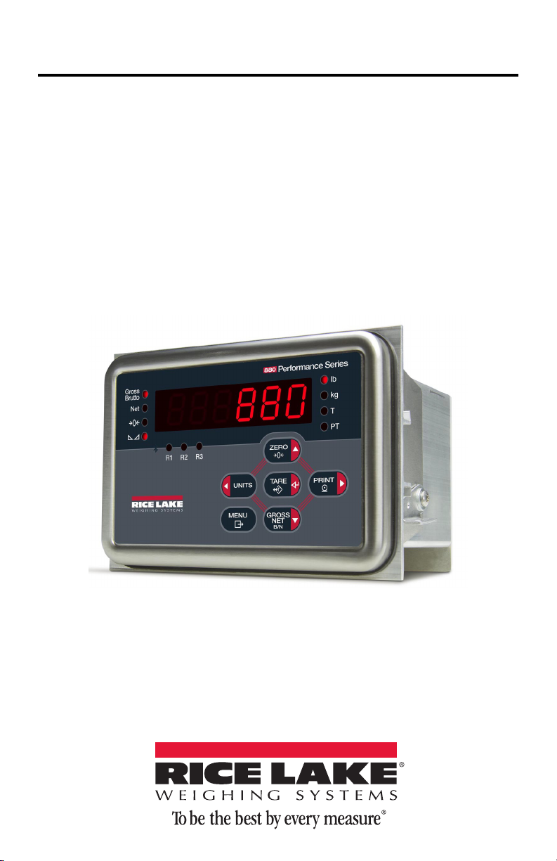
880 Performance Series
Panel Mount Controller/Indicator
Version 1.01
Operation Manual
152240 - Rev C
Page 2

Page 3

Contents
Technical training seminars are available through Rice Lake Weighing Systems.
Course descriptions and dates can be viewed at www.ricelake.com/training
or obtained by calling 715-234-9171 and asking for the training department.
About This Manual ................................................................................ 1
1.0 Introduction............................................................................... 1
1.1 Safety . . . . . . . . . . . . . . . . . . . . . . . . . . . . . . . . . . . . . . . . . . . . . 2
1.2 Operating Modes . . . . . . . . . . . . . . . . . . . . . . . . . . . . . . . . . . . . 3
1.3 Front Panel Display . . . . . . . . . . . . . . . . . . . . . . . . . . . . . . . . . . . 3
1.4 Indicator Operations . . . . . . . . . . . . . . . . . . . . . . . . . . . . . . . . . . 6
1.4.1 Toggle Gross/Net Mode . . . . . . . . . . . . . . . . . . . . . . . . . . . . . 6
1.4.2 Toggle Units . . . . . . . . . . . . . . . . . . . . . . . . . . . . . . . . . . . . . . 6
1.4.3 Zero Scale. . . . . . . . . . . . . . . . . . . . . . . . . . . . . . . . . . . . . . . . 6
1.4.4 Acquire Tare . . . . . . . . . . . . . . . . . . . . . . . . . . . . . . . . . . . . . . 6
1.4.5 Remove Stored Tare Value . . . . . . . . . . . . . . . . . . . . . . . . . . . 6
1.4.6 Preset Tare (Keyed Tare) . . . . . . . . . . . . . . . . . . . . . . . . . . . . . 7
1.4.7 Print Ticket . . . . . . . . . . . . . . . . . . . . . . . . . . . . . . . . . . . . . . . 7
1.4.8 Front Panel Setup . . . . . . . . . . . . . . . . . . . . . . . . . . . . . . . . . . 7
1.4.9 Displaying Audit Trail Information . . . . . . . . . . . . . . . . . . . . . . . 7
1.4.10 Setpoints . . . . . . . . . . . . . . . . . . . . . . . . . . . . . . . . . . . . . . . . . 8
1.4.11 Set Time and Date. . . . . . . . . . . . . . . . . . . . . . . . . . . . . . . . . . 9
1.4.12 Display Accumulator . . . . . . . . . . . . . . . . . . . . . . . . . . . . . . . . 9
1.4.13 Clear the Accumulator . . . . . . . . . . . . . . . . . . . . . . . . . . . . . . 10
1.4.14 Display Tare. . . . . . . . . . . . . . . . . . . . . . . . . . . . . . . . . . . . . . 10
2.0 Configuration .......................................................................... 11
2.1 Configuration Methods . . . . . . . . . . . . . . . . . . . . . . . . . . . . . . . 11
2.1.1 Revolution® Configuration. . . . . . . . . . . . . . . . . . . . . . . . . . . 11
2.1.2 EDP Command Configuration . . . . . . . . . . . . . . . . . . . . . . . . 12
2.1.3 Front Panel Configuration . . . . . . . . . . . . . . . . . . . . . . . . . . . 12
2.1.4 Alphanumeric Entry Procedure . . . . . . . . . . . . . . . . . . . . . . . 14
2.2 Menu Structures and Parameter Descriptions . . . . . . . . . . . . . . 14
2.2.1 Audit Menu . . . . . . . . . . . . . . . . . . . . . . . . . . . . . . . . . . . . . . 14
2.2.2 Setup Menu. . . . . . . . . . . . . . . . . . . . . . . . . . . . . . . . . . . . . . 15
2.2.3 Scale Menu . . . . . . . . . . . . . . . . . . . . . . . . . . . . . . . . . . . . . . 15
2.2.4 Feature Menu . . . . . . . . . . . . . . . . . . . . . . . . . . . . . . . . . . . . 18
2.2.5 Ports Menu . . . . . . . . . . . . . . . . . . . . . . . . . . . . . . . . . . . . . . 20
2.2.6 Ethernet Communications Menu . . . . . . . . . . . . . . . . . . . . . . 22
2.2.7 USB Host . . . . . . . . . . . . . . . . . . . . . . . . . . . . . . . . . . . . . . . 22
2.2.8 Print Format Menu. . . . . . . . . . . . . . . . . . . . . . . . . . . . . . . . . 23
2.2.9 Setpoint Menu. . . . . . . . . . . . . . . . . . . . . . . . . . . . . . . . . . . . 23
2.2.10 Digital Input/Output Menu . . . . . . . . . . . . . . . . . . . . . . . . . . . 26
© Rice Lake Weighing Systems. All rights reserved. Printed in the United States of America.
Rice Lake Weighing Systems is an ISO 9001 registered company.
i 880 Operator’s Manual
Specifications subject to change without notice.
Version 1.01, June 20, 2014
Page 4

Rice Lake continually offers web-based video training on a growing selection
of product-related topics at no cost. Visit www.ricelake.com/webinars.
2.2.11 Analog Output Menu . . . . . . . . . . . . . . . . . . . . . . . . . . . . . . . 26
2.2.12 Version Menu . . . . . . . . . . . . . . . . . . . . . . . . . . . . . . . . . . . . 26
3.0 Appendix ................................................................................. 27
3.1 Displayed Error Messages. . . . . . . . . . . . . . . . . . . . . . . . . . . . . 27
3.2 Specifications . . . . . . . . . . . . . . . . . . . . . . . . . . . . . . . . . . . . . . 28
880 Limited Warranty.......................................................................... 30
Contents ii
Page 5

About This Manual
This manual is intended for use the operator of the 880 digital weight indicators and
applies to indicators using Version 1.01 of the 880 software.
The Technical/Service manual (PN 158387) that is referred to throughout this manual
and is available online.
Manuals can be viewed or downloaded the Rice Lake Weighing Systems
website at
www.ricelake.com/manuals.
Please leave this manual with the indicator when installation and configuration are
complete.
1.0 Introduction
The 880 is a single-channel digital weight indicator housed in a panel mount
enclosure. The front panel bezel can be sealed to a NEMA 4X/IP65 rating. The front
panel consists of a 6-button keypad; a large, seven-digit, 14-segment, vacuum
fluorescent display; two-character dot-matrix annunciator field; and 16-character dotmatrix prompt field. Features include:
• Drives up to 8 350
• Supports four and six wire load cell connections
• Four configurable digital inputs or outputs
• Full duplex RS-232 or half duplex RS-485 communications up to 115200 bps
• Ethernet TCP/IP interface for 10Base-T/100Base-TX network communications
• USB interface for host (type A connection) or device
• Expansion slot for one option card
• Optional DeviceNet
Bradley
®
controllers
• Optional Ethernet/IP interface for Allen-Bradley PLC and other Ethernet/IP
master devices
• Optional Profibus® DP interface
• Optional Modbus TCP interface
• Optional Profinet Interface
• Optional analog output module provides 0–10 VDC, 0-20mA or 4–20 mA
tracking of gross or net weight values
• Optional four channel relay module, dry connect 3A @ 115VAC, 3A @ 30VDC
• Available in 115 VAC and 230 VAC versions
or 16 700 load cells
™
interface for communications network with Allen-
1
3
2
1. DeviceNet™ is a trademark of the Open DeviceNet Vendor Association.
2. Profibus
3. EtherNet/IP
1 880 Operator’s Manual
®
is a registered trademark of Profibus International.
™
is a trademark of the Open DeviceNet Vendor Association.
Page 6
1. 1 S af et y
WARNING
CAUTION
Important
WARNING
WARNING
Safety Symbol Definitions
Indicates a potentially hazardous situation that, if not avoided,
could result in serious injury or death, and includes hazards that
are exposed when guards are removed.
Indicates a potentially hazardous situation that, if not avoided,
may result in minor or moderate injury.
Indicates information about procedures that, if not observed,
could result in damage to equipment or corruption to and loss of
data.
Safety Precautions
Do not operate or work on this equipment unless you have read
and understand the instructions and warnings in this manual.
Failure to follow the instructions or heed the warnings could
result in injury or death. Contact any Rice Lake Weighing
Systems dealer for replacement manuals. Proper care is your
responsibility.
Some procedures described in this manual require work inside
the indicator enclosure. These procedures are to be performed by
qualified service personnel only.
General Safety
Failure to heed may result in serious injury or death.
DO NOT allow minors (children) or inexperienced persons to operate this unit.
DO NOT operate without all shields and guards in place.
DO NOT step on the unit.
DO NOT jump on the scale.
DO NOT use for purposes other than weight taking.
DO NOT place fingers into slots or possible pinch points.
DO NOT use any load-bearing component that is worn beyond 5% of the original
dimension.
DO NOT use this product if any of the components are cracked.
DO NOT exceed the rated load limit of the unit.
DO NOT make alterations or modifications to the unit.
DO NOT remove or obscure warning labels.
DO NOT use near water.
Before opening the unit, ensure the power cord is disconnected from the outlet.
Keep hands, feet and loose clothing away from moving parts.
Introduction 2
Page 7

1.2 Operating Modes
Gross
Brutto
Net
lb
kg
PT
T
MENU
ZERO
PRINT
GROSS
NET
B/N
TAR E
UNITS
R1 R2 R3
The 880 has three modes of operation:
Normal mode
Normal mode is the weighing mode of the indicator. The indicator
displays gross or net weights as required, and annunciators to indicate
scale status and the type of weight value displayed.
User Setup Mode
User setup mode (accessed by pressing MENU) is used to:
• View the audit trail
• Set the time and date
• View or clear the accumulator value
• Change setpoint values
• View the current tare value
• Enter setup mode (if audit trail is enabled)
See Section 1.4.8 for more information.
1.3 Front Panel Display
Figure 1-1 shows the 880 front panel keys and the key functions assigned in normal
mode.
The numeric display consists of six large, 14-segment LED digits. If a negative
number is displayed the first LED is used to display “-”, reducing the number of
available digits to five.
The symbols on the keys in Figure 1-1 (representing up, down, enter, left, right)
describe the key functions assigned in setup mode. The keys are used to navigate
through menus, select digits within numeric values, and increment/decrement values.
See Section 2.1.3 for information about using the front panel keys in setup mode.
3 880 Operator’s Manual
Page 8
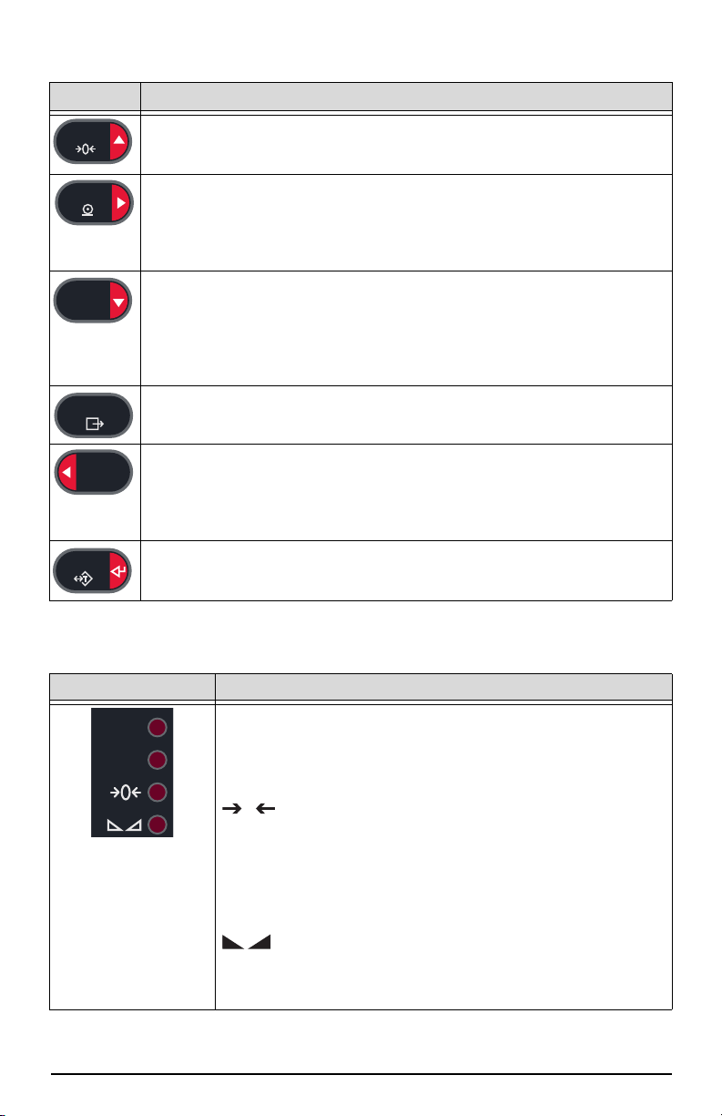
Figure 1-1. 880 Front Panel Display
ZERO
PRINT
GROSS
NET
B/N
MENU
UNITS
TAR E
Gross
Brutto
Net
0
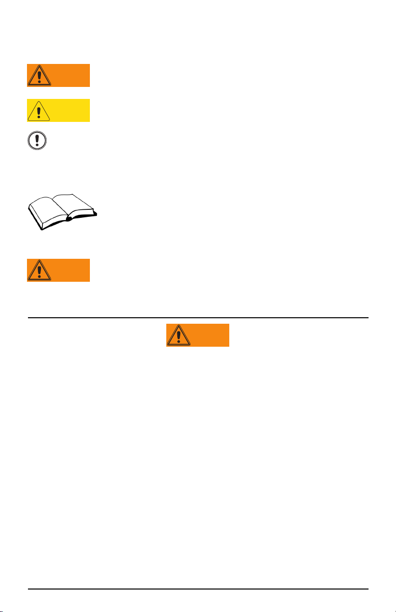
Key Function
Sets the current gross weight to zero.
Also used to navigate to different menu levels or used to increment a
number when editing a value.
Sends “on-demand” print format out the serial port, provided the
conditions for standstill are met. PRINT may be displayed while the unit
prints.
Also used to navigate to different menus or to toggle to another digit when
editing a value.
Toggles between gross and net. If a tare value has been entered or
acquired, the net value is the gross weight minus the tare.
Gross mode is shown by the Gross/Brutto annunciator; net mode is
shown by the Net annunciator.
Also used to navigate to different menu levels or to decrement a number
when editing a value.
The MENU key is used to access the setup menu.
Also acts as the cancel key when editing parameter values.
Switches the weight display to an alternate unit, defined in the Format
menu, see Technical/Service manual for more information.
Units Available: lb, kg, oz, metric ton, ton, gram.
Also used to navigate to different menus or to toggle to another digit when
editing a value.
Performs one of several predetermined Tare functions dependent on the
mode of operation selected in the TAREFN parameter.
Also acts as enter for numeric or parameter entry.
Table 1-1. Key Functions
Key Function
Gross/Brutto LED
Gross weight mode (or Brutto in OIML mode)
Net LED
Net weight mode.
Center of Zero LED
Indicates that the current gross weight reading is within +/-
0.25 display divisions of the acquired zero, or is within the
center of zero band.
A display division is the resolution of the displayed weight
value, or the smallest incremental increase or decrease that
can be displayed or printed.
Standstill LED
Scale is at standstill or within the specified motion band. Some
operations, including Zero, Tare and Printing, can only be done
when the standstill LED is on.
Table 1-2. Annunciator Functions
Introduction 4
Page 9
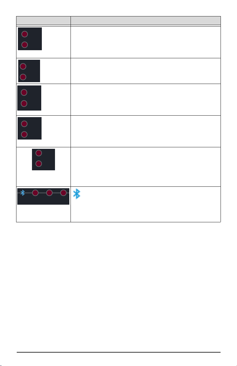
Key Function
lb
kg
kg
lb
lb
kg
primary
secondary
lb
kg
tn, t, oz,
lb
g or none
lb
kg
tn, T, oz,
kg
g or none
PT
T
R1 R2 R3
lb/kg LED
Displays which unit of measure is being used.
The lb and kg annunciators indicate the units associated with
the displayed value. If the displayed value is pounds, lb will be
lit. If the displayed value is kilograms, kg will be lit.
primary/secondary LED
If the other units value is neither lb or kg, then lb will be lit for
the units assigned as primary, and kg will be lit for the units
assigned as secondary.
lb/tn,t,oz,g,none LED
Alternate units that can be displayed include short tons (tn),
metric tons (t), ounces (oz), grams (g), or NONE (no units). If the
displayed units is one of these alternate units, and the other
unit value is lb, then lb will be lit.
tn,t,oz,g,none /kg LED
Alternate units that can be displayed include short tons (tn),
metric tons (t), ounces (oz), grams (g), or NONE (no units). If the
displayed units is one of these alternate units, and the other
unit value is kg, then kg will be lit.
T LED
Indicates that a tare has been acquired and stored by the
system.
PT LED
Indicates that a preset tare weight has been keyed in or
entered via the EDP serial port.
5 880 Operator’s Manual
Bluetooth
Bluetooth communications enabled
R1, R2 and R3
Range settings for multi interval or multi range
Table 1-2. Annunciator Functions
Page 10
1.4 Indicator Operations
GROSS
NET
B/N
Note
UNITS
ZERO
0
Note
TAR E
TAR E
ZERO
Note
TAR E
TAR E
Basic 880 operations are summarized below:
1.4.1 Toggle Gross/Net Mode
1. Press to toggle the display mode between gross and net.
Net mode is available when a tare value has been entered or acquired,
(NET = GROSS minus TARE). If tare has not been entered or acquired, the
display remains in gross mode. LEDs next to Gross or Net indicates the
current mode.
1.4.2 Toggle Units
1. Press to switch between primary and secondary units. The current
units LED will be lit.
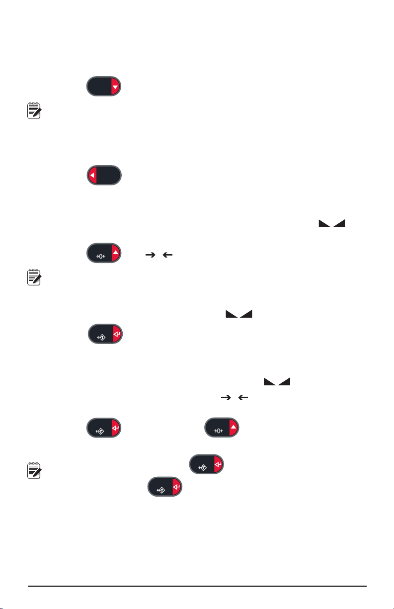
1.4.3 Zero Scale
1. In gross mode, remove all weight from the scale and wait for the LED
to light.
2. Press . The LED lights to indicate the scale is zeroed.
The scale must be stable and within the configured zero range, for the
scale to be zeroed. If the scale cannot be zeroed, NOZERO will display.
1.4.4 Acquire Tare
1. Place container on scale and wait for the LED to light.
2. Press to acquire the tare weight of the container. Net weight is
displayed and the T LED lights to show the tare value was entered.
1.4.5 Remove Stored Tare Value
1. Remove all weight from the scale and wait for the LED to light.
2. The display should read zero and the LED should be lit, zero the
scale if needed.
3. Press (or, in OIML mode ). Display shifts to gross weight
and the Gross LED is lit.
If keyed tare is allowed, press to open the keyed tare prompt. To
clear the tare press again.
0
Introduction 6
Page 11
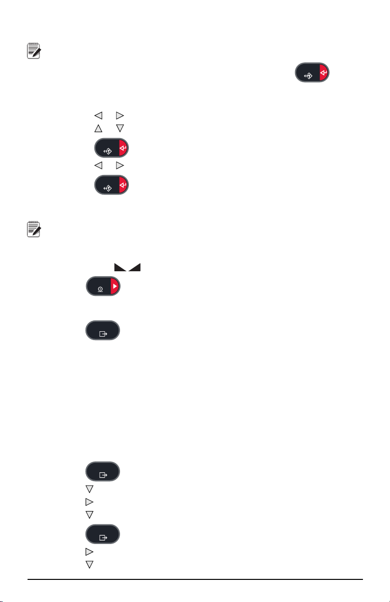
1.4.6 Preset Tare (Keyed Tare)
Note
TAR E
TAR E
TAR E
Note
PRINT
MENU
MENU
MENU
Tare mode must be set to keyed or both for preset tare to function.
1. With the scale empty and zero weight on the display, press .
2. Display will show (000000); the focused digit will flash.
3. To edit the value:
• Press or to select the digit.
• Press or to increment or decrement the value.
• Press to move to the decimal point entry.
• Press or to adjust the decimal point placement.
• Press when the value is correct.
4. The display will change to the Net mode and the
PT LED lights to show the
preset tare was entered.
Entering a keyed tare of zero will remove the stored tare value.
1.4.7 Print Ticket
1. Wait for the ( ) LED to light.
2. Press to send data to a communications port.
1.4.8 Front Panel Setup
1. Press to enter user setup mode. Use user setup to:
• View audit trail information
• Enter setup mode if audit trail is enabled
• View or set time and date
• View or clear the accumulator
• Change setpoint values and enable/disable setpoints
• View the current tare value
1.4.9 Displaying Audit Trail Information
The Audit Trail Configuration and Calibration counters can be viewed through the
User Menu.
1. Press ,
2. Press to display the Legally Relevant Firmware version.
3. Press to display
4. Press to view the Calibration Counter.
5. Press to return to
6. Press to display
7. Press to view the Configuration Counter.
7 880 Operator’s Manual
AUDIT is displayed.
CALIB.
CALIB.
CFG.
Page 12

8. Press to return to CFG.
MENU
MENU
MENU
Note
MENU
TAR E
TAR E
MENU
Note
9. Press to return to the weigh mode.
1.4.10 Setpoints
Setpoints must be enabled in the setup mode to be accessible in the user setup mode.
To enter the setup mode:
1. Remove the large fillister head screw from the back of the enclosure.
2. Insert a nonconductive tool into the access hole and press the setup switch.
Indicator display changes to show
3. Press or until
4. Press ,
SP CFG is displayed.
SETPTS is displayed.
5. Press , press or to desired setpoint number.
6. Press to enter setpoint settings.
7. Select the type by pressing or to desired setting, then press to set the
value. For complete list of options see Section 3.2.13.
8. When all settings have been made, press to return to weighing
mode.
Setpoints are now accessible from the front panel menu.
Display or Edit Setpoint Value
1. Press . AUDIT is displayed.
2. Press or until
3. Press and the first available setpoint number is displayed.
4. Press or to toggle through each setpoint that is operator accessible.
5. Press , is displayed.
6. Press again to display or edit the value. To edit the value:
• Press or to increment or decrement the value of the flashing digit.
• Press or to select the digit to edit.
SETPTS is displayed.
SCALE.
• Press to move to the decimal point entry.
• Press or to adjust the decimal point placement.
7. Press to accept the displayed value.
8. Repeat the above steps to set
PREACT, if enabled
9. When all settings have been made, press to return to weighing
mode.
Setpoint Value and Preact Value may be accessible from the front panel
in weigh mode.
Some indicator configurations may not allow setpoint values to be
changed through the front panel or may require a password to display or
change the setpoint value.
Introduction 8
Page 13

Turn Setpoint On or Off
MENU
TAR E
MENU
Note
MENU
TAR E
TAR E
MENU
MENU
To turn a setpoint off at the front panel:
1. Press . AUDIT is displayed.
2. Press or until SETPTS is displayed.
3. Press and the first available setpoint number is displayed.
4. Press or to toggle through each setpoint that is operator accessible.
5. Press , then press or to
6. Press , then press or to turn setpoint
ENABLE/DISABLE.
ON/OFF.
7. Press to accept the setting.
8. Press to return to weighing mode.
Some indicator configurations may not allow setpoints to be turned off
through the front panel or may require a password to turn the setpoint on
and off.
1.4.11 Set Time and Date
1. Press , AUDIT is displayed.
2. Press or until
3. Press ,
TIME is displayed.
4. Press , to enter time.
5. To edit the value ( 24 hour format):
• Press or to select the digit.
• Press or to increment or decrement the value.
T&D is displayed.
6. Press when the value is correct.
DATE is displayed.
7. Press , to enter time.
8. To edit the value in specified format (MMDDYY, DDMMYY, or YYMMDD):
• Press or to select the digit.
• Press or to increment or decrement the value.
9. Press when the value is correct.
TIME is displayed.
10. Press to return to weighing mode.
1.4.12 Display Accumulator
Enable accumulator before use in either normal mode or setpoint operations. Once
enabled, weight (net weight if a tare is in the system) is accumulated whenever a print
operation is performed using the
operation or KPRINT serial command. The scale must return to below the threshold
value (except for the setpoint
1. Press to enter the user setup mode, AUDIT is displayed.
2. Press or until ACCUM is displayed.
9 880 Operator’s Manual
PRINT key, digital input, setpoint PSHACC
PSHACC operation) before the next accumulation.
Page 14

ACCUM
Note
PRINT
Note
MENU
TAR E
MENU
Note
MENU
MENU
is only displayed if the accumulator is enabled.
3. Press , VIEW is displayed.
4. Press to view the current accumulator value.
5. While the accumulator value is displayed, press to print the value.
The format of the print ouput can be configured using accumulator print
format. See Section 7.0.
1.4.13 Clear the Accumulator
1. Press to enter the user setup mode, AUDIT is displayed.
2. Press or until
3. Press , then press or until
ACCUM is displayed.
CLR Y is displayed.
4. Press to clear the accumulator,
display returns to
CLR Y.
CLEAR will display briefly and
5. Press to return to the weigh mode.
The PRINT key only performs one accumulation. Weight must return to
zero below the configured threshold value before another accumulation
is allowed.
Threshold is configured in the setup menu, see Section 3.2.3.
1.4.14 Display Tare
When a stored Tare value is displayed, the Gross and Net LEDs will be off and the
will be lit. To display a stored tare:
1. Press .
2. Press to
3. Press twice to return to weighing mode.
If there is no tare in the system, the value displayed will be zero and the Gross and
Net LED will be turned off.
See the Technical Service Manual (PN 158387) for more information pertaining to
the regulatory mode of operation.
TAR E and press to view the current tare value.
Introduction 10
Page 15

2.0 Configuration
Important
Note
MENU
J1 J2 J3 J4 J5 J6
Setup
Switch
Access
MENU
Note
To configure the 880 indicator, the indicator must be placed in setup mode. The setup
switch is accessed through a small hole on the enclosure backplate, insert a nonconductive tool into the access hole and press the configuration switch. Indicator
display changes to show
Use caution when inserting the non-conductive tool into the
backplate, press the tool in about 3/4 inch, using the board as a
guide, until the switch is engaged. Do not use excessive force, the
switch may be damaged.
CONFIG.
If audit trail is enabled, press
Press or until SETUP is displayed, then press to SCALE.
to access setup mode.
.
Figure 2-1. Back View – Setup Switch Access
When the indicator is placed in setup mode, the word
CONFIG is shown on the
display. The CONFIG menu is the first of ten top-level menus used for configuring
the indicator. Detailed descriptions of these menus are given in Section 2.2. When
configuration is complete, return to the CONFIG menu and press the (
ZERO) key
to exit setup mode.
When configuration is complete, press to return to the weigh mode.
2.1 Configuration Methods
The 880 indicator can be configured by using the front panel keys to navigate through
a series of configuration menus or by sending commands or configuration data to the
EDP port. Configuration using the menus is described in Section 2.1.3.
Configuration using the EDP port can be accomplished using either the EDP
command set described in the Technical Service manual or Version 3.0 or later of the
Revolution
®
configuration utility.
2.1.1 Revolution® Configuration
The Revolution configuration utility provides the preferred method for configuring
the 880 indicator. Revolution runs on a personal computer to set configuration
parameters for the indicator. When Revolution configuration is complete,
configuration data is downloaded to the indicator.
See Section 5.0 of the Technical/Service manual (PN 158387) for more
information on Revolution.
11 880 Operator’s Manual
Page 16

2.1.2 EDP Command Configuration
000000
000000
ACCUM
Displayed only
if turned on in
Scale Menu
AUDIT
TARE
SETPTST & D ACCUMSETUP
000000
DATE
TIME
No Access
unless the
jumper is
installed
VIEW CLR Y?
000000
See
Figure 2-7
See
Figure 2-6
See
Figure 2-18
The EDP command set can be used to configure the 880 indicator using either a
personal computer or terminal. Like Revolution, EDP command configuration sends
commands to the indicator EDP port; unlike Revolution, EDP commands can be sent
using any external device capable of sending ASCII characters over a serial
connection.
EDP commands duplicate the functions available using the indicator front panel and
provide some functions not otherwise available. EDP commands can be used to
simulate pressing front panel keys, to configure the indicator, or to dump lists of
parameter settings. See the Technical Service manual for more information about
using the EDP command set.
2.1.3 Front Panel Configuration
The 880 indicator can be configured using a series of menus accessed through the
indicator front panel when the indicator is in setup mode. Table 2-1 summarizes the
functions of each of the main menus.
Figure 2-2. 880 Menu Layout
Menu Menu Function
AUDIT Audit Trail Displays the legally relevant (LR) firmware version,
SETUP Setup
T&D Time and Date View and change time and date.
ACCUM Accumulator Displays the current accumulator value.
SETPTS Setpoints Configure setpoints.
TA R E Ta re Ta re f u n c t i o n . E n a b l e s or disables push-button and
configuration count and calibration count.
keyed tare
Table 2-1. 880 Menu Summary
Configuration 12
Page 17

Figure 2-3. Five-Key Keypad Functions in Setup Mode
T
MENU
ZERO
PRINT
GROSS
NET
B/N
TA RE
UNITS
Level 1
Parameter
Current value
Level 2
Parameter
Value Value Value
Level 1
Parameter
Level 2
Parameter
When moving through values below the first menu level, press to return to the level
above.
0 0 0 0 0 0
When editing numeric values, press or to change the selected digit.
Press or to increment or decrement the value of the selected digit.
After the number desired is displayed, press ENTER. The decimal point
will begin flashing if a decimal value is allowed. To move the decimal,
use or to move the decimal position. Press ENTER when done.
Four front panel keys are used as directional keys to navigate through the menus in
setup mode (see Figure 2-3). The
(horizontally) on the same menu level;
down (vertically) to different menu levels. The
UNITS ( ) and PRINT ( ) keys scroll left and right
ZERO () and GROSS/NET ( ) move up and
TARE key ( ) serves as an Enter key
for selecting parameter values within the menus.
Figure 2-4. Setup Mode Menu Navigation
To select a parameter, press or to scroll left or right until the desired menu group
appears on the display, then press to move down to the submenu or parameter you
want. When moving through the menu parameters, the default or previously selected
value appears first on the display.
To change a parameter value, scroll left or right to view the values for that parameter.
When the desired value appears on the display, press to select the value and move
back up one level. To edit numerical values, use the navigation keys to select the digit
and to increment or decrement the value.
13 880 Operator’s Manual
Figure 2-5. Editing Procedure for Numeric Values
Page 18

2.1.4 Alphanumeric Entry Procedure
Display first 6
characters of format
Display and edit
active character and
ASCII value
Delete active
character
Scroll right in format string
Scroll left in format string
Increment ASCII value of active character
Decrement ASCII value of active character
Press to insert a space
before the active character
Press to accept the changes
and return to the level above.
Level 2
Parameter
Level 1
Parameter
Level 2
Parameter
Level 1
Parameter
Press to accept the changes
and return to the level above.
LRV 1.00
number
AUDIT
TARE
SETPTST & D
ACCUMSETUP
CALIB CFG
number
Because of its limited keypad, the 880 will use the following scheme for
alphanumeric entry.
Table 2-2. Editing Procedure for Numeric Values
2.2 Menu Structures and Parameter Descriptions
The following sections provide graphic representations of the 880 menu structures. In
the actual menu structure, the settings you choose under each parameter are arranged
horizontally. To save page space, menu choices are shown in vertical columns. The
factory default setting appears at the top of each column and is bolded. Parameters
shown surrounded by a dotted-line box only appear under the special circumstances
explained under each box.
Most menu diagrams are accompanied by one or more tables that describe all
parameters and parameter values associated with that menu option. Default parameter
values are shown in bold type.
2.2.1 Audit Menu
AUDIT Menu
Parameter Choices Description
LRV --- Legally relevant firmware version
CALIB 000000 Displays total calibration events.
CFG 000000 Displays total configuration events.
Figure 2-6. Audit Menu Structure
Table 2-3. Audit Menu Parameters
Configuration 14
Page 19

2.2.2 Setup Menu
SCALE FEATUR PORTS
PFORMT
SETPTS DIGIO ALGOUT VERS
AUDIT TARESETPTST & D ACCUMSETUP
10000
1-100000
....
30HZ
7.5HZ
15HZ
60HZ
120HZ
240HZ
480HZ
960HZ
LIGHT
MEDIUM
HEAVY
SETUP
........
SCALE
GRADS
OFF
2RNG
3RNG
2INTVL
3INTVL
SPLIT MOTBAN
0-1000-100
ZRANGEZTRKBNFORMAT
0-100
DSPRAT
1-80
FS+2%
FS+ 1D
FS+ 9D
FS
OVRLOA SSTIME
1-65536
SMPRAT DFTHRHDFSENS TAREFN
1-99999
BOTH
NOTARE
PBTARE
KEYED
THRESH CALIBRPWRUPM ACCUM
GO
DELAY
OFF
ON
0-999999
See
Figure 2-9
See
Figure 2-10
2.2.3 Scale Menu
Figure 2-7. Setup Menu Structure
15 880 Operator’s Manual
Figure 2-8. Scale Menu Structure
Page 20

Format Menu
........
SCALE
....
FORMAT
PRI
1D
2D
5D
DSPDIV
DECPNT
888888
888880
8.88888
88.8888
888.888
8888.88
88888.8
SETUP
........
UNITS
LB
KG
OZ
TN
T
G
NONE
SEC
5D
1D
2D
DSPDIV
DECPNT
88888.8
888888
888888
8.88888
88.8888
888.888
8888.88
UNITS
LB
KG
OZ
TN
T
G
NONE
........
SCALE
....
FORMAT
1D
2D
5D
DDIV1DECPT1
888888
888880
8.88888
88.8888
888.888
8888.88
88888.8
SETUP
....
....
MAX1
2000
weight
5D
1D
2D
DDIV2
DECPT2
88888.8
888888
888880
8.88888
88.8888
888.888
8888.88
5D
1D
2D
DDIV3DECPT3
88888.8
888888
888880
8.88888
88.8888
888.888
8888.88
UNITS
LB
KG
OZ
TN
T
G
NONE
MAX2
5000
weight
MAX3
10000
weight
Only available if
SPLIT = 3RNG or 3INTVL
If SPLIT = OFF
If SPLIT = 2RNG, 3RNG, 2INTVL, or 3INTVL
Figure 2-9. Format Menu Structure
Configuration 16
Page 21

Calibration Menu
SCALE
....
....
....
CALIBR
SETUP
....
....
Display and edit
test weight value
WVAL WLIN
POINT1
Same as POINT 1
REZERO
Calibrating, please wait
Press Enter to
compensate for
zero offset
WGT 1
WZERO
Calibrating, please wait
Press Enter
to calibrate zero
Press Menu
to cancel
Previous A/D raw
counts are shown
CAL1
POINT2 POINT3 POINT4 POINT5
WSPAN
Calibrating, please wait
Press Enter
to calibrate span
Press Menu
to cancel
Previous A/D raw
counts are shown
LAST
Calibrating, please wait
Press enter to recall
the last established
pushbutton zero value
to allow calibration
without removing test
weights from the scale.
TEMP
Calibrating, please wait
Press enter to
temporarily zero the
displayed weight of a
non-empty scale.
After span calibration
the previously
calibrated zero value
is used as the offset.
Calibrating, please wait
Press Enter
to calibrate span
Press Menu
to cancel
Previous A/D raw
counts are shown
Display and edit
test weight value
Figure 2-10. Calibration Menu Structure
17 880 Operator’s Manual
Page 22

2.2.4 Feature Menu
CONFIG
....
SETUP
........
REGION
000000
UID
KEYLCK
ZERO
UNLOCK
LOCK
UNITS
UNLOCK
LOCK
PRINT
UNLOCK
LOCK
TARE
UNLOCK
LOCK
MENU
UNLOCK
LOCK
GRSNET
UNLOCK
LOCK
0
RESVAL
LOCALE
OFF
ON
0
CURVAL
CONSC#
PASSWD
USER
0
SETUP
0
FEATUR
LATUDE
0-90
ELEVAT
-9999 to +9999
Shown if LOCALE is ON
See
Figure 2-12
Figure 2-11. Feature Menu Structure
Configuration 18
Page 23

Region Menu
SETUP
........
TFORMT T SEP SET
DFORMT D SEP SET
REGION
REGULA
REGWOR DECFMT
TIME DATE
NTEP
CANADA
INDUST
GROSS
BRUTTO
DOT
COMMA
NONE
OIML
24 HOUR
COLON
COMMA
XX.XXAM
000000
MMDDY4
DDMMY4
Y4MMDD
Y4DDMM
SLASH
DASH
SEMI
MMDDY2
DDMMY2
Y2MMDD
Y2DDMM
12 HOUR
....
FEATUR
SNPSHT
DISPLY
SCALE
ZTARE
NO
YES
KTARE
MTARE
REMOVE
REPLAC
NOTHIN
YES
NO
PRTMOT
NO
YES
PRTPT
NO
YES
CALIB
SCALE
NTEP
NONE
OIML
CANADA
NO
YES
NTARE
NO
YES
OVRBAS
CTARE
See INDUST
submenu below
AUDAG
Figure 2-12. Region Menu Structure
19 880 Operator’s Manual
Page 24

2.2.5 Ports Menu
SETUP
........
COM
SWAP
FLDBUS
USBCOM
....
PORTS
....
BYTE
BOTH
NONE
DVCNET
PRFBUS
Address Address
number number
USB
MEM
ETHNET
LOAD SAVE?
ALL ?
CFG ?
CAL ?
See
Figure 2-14
See
Figure 2-15
Figure 2-13. Ports Menu Structure
Configuration 20
Page 25

Com and USBCOM Menu
SETUP
.......
COM
....
PORTS
TRIGGE
STRIND
COMAND
STRLFT
REMOTE
STOP B
1
2
TERMIN
CR
CR/LF
ECHO
ON
OFF
EOLDLY
0-255
PRNMSG
OFF
ON
BAUD
1200
2400
4800
9600
19200
28800
38400
57600
115200
RESPNS
ON
OFF
TRIGGE
REMOTE
BITS
7ODD
7EVEN
8NONE
STOP B
1
2
BAUD
1200
2400
4800
9600
19200
28800
38400
57600
115200
PRNMSG
OFF
ON
SFMT
format
Menu Structure if TRIGGE is set to REMOTE.
BITS
7EVEN
8NONE
7ODD
USBCOM
TYPE
232
485
ADDRES
0-255
Only Available
if TYPE is
set to 485
Not available in USBCOM
Not available in USBCOM
SFMT
format
Menu Structure if
TRIGGE is set to
STRIND or STRLFT.
21 880 Operator’s Manual
Figure 2-14. Com Menu Structure
Page 26

2.2.6 Ethernet Communications Menu
SETUP
........
....
PORTS
ETHNET
DHCP
ON
OFF
IPADRS
xxx.xxx.xxx.xxx
NETMSK
xxx.xxx.xxx.xxx
DFTGWY
xxx.xxx.xxx.xxx
DNSPRI
xxx.xxx.xxx.xxx
DNSSEC
xxx.xxx.xxx.xxx
MACSERVER
PORT
number
TRIGGE
STRLFT
COMAND
STRIND
TERMIN
CR/LF
CR
EOLDLY
number
TIMOUT
number
SFMT
ECHO
OFF
ON
ON
OFF
RESPNS
RMOTIP TRIGGE
STRLFT
COMAND
STRIND
TERMIN
CR/LF
CR
EOLDLY
number
TIMOUT
number
ECHO
OFF
ON
ON
OFF
RESPNS
RMOTPT
number
SFMT
ALPHA/NUM
ALPHA/NUM
xxx.xxx.xxx.xxx
xx.xx.xx.xx.xx.xx
CLIENT
USB
MEM
LOAD SAVE?
ALL ?
CFG ?
CAL ?
2.2.7 USB Host
Figure 2-15. Ethernet Communications Menu Structure
......
Figure 2-16. USB Host Menu Structure
Configuration 22
Page 27

2.2.8 Print Format Menu
PFORMT
....
....
SETUP
....
....
GFMT
FMT
COM
ETH-S
USBCOM
PORT
format
NFMT SPFMTACCFMT HDRFMT
format
USBMEM
ETH-C
OFF
Note
SETUP
.....
SP CFG
....
SETPTS
SETPT1
BATCHG
SETPT2-20
OFF
AUTO
MANUAL
Same as
SETPT1
OFF
GROSS
NET
-GROSS
-NET
%REL
PAUSE
DELAY
WAITSS
COUNTR
AUTJOG
TIMER
CONCUR
See Figure 2-19
Menu Layout A
See Figure 2-20
Menu Layout B
See Figure 2-21
Menu Layout C
Figure 2-17. Print Format Menu Structure
See Technical/Service Manual (158387) for port choice descriptions.
2.2.9 Setpoint Menu
23 880 Operator’s Manual
Figure 2-18. Setpoint Menu Structure
Page 28

Setpoint Menu – Layout A
A
GROSS, NET, -GROSS, -NET, %REL
%RELSP Only
If PREACT is LEARN
number
VALUE
HIGHER
LOWER
INBAND
OUTBAN
TRIP
If TRIP=
HIGHER or
LOWER
number
HYSTER
OFF
ON
LEARN
PREACT
If TRIP=
INBAND or
OUTBAND
number
BANDVAL
RELNUM
1–20
PREVAL
If PREACT is
ON or LEARN
number
PREADJ
number
PRESTA
number
PCOUNT
number
BATSEQ
OFF
ON
CLRACM
OFF
ON
CLRTAR
OFF
ON
PSHPRT
OFF
ON
WAITSS
PSHTAR
OFF
ON
ACCESS
ON
OFF
DIGOUT
BIT1-4
PSHACM
OFF
ON
ONQUIE
NAME
6ALPHA
SENSE
NORMAL
INVERT
BRANCH
0
1-20
Based on which
DIGIO are config
as OUTPUT
If BATSEQ is ON
NONE
SLOT
SLOT 0
SLOT 1
SLOT 0 - if any DIGIO are configured as OUTPUT.
SLOT 1 - if RELAY option board is installed.
Figure 2-19. Setpoint Menu Structure – Layout A
Configuration 24
Page 29

Setpoint Menu – Layout B
B
PAUSE, DELAY, WAITSS, COUNTR, AUTJOG
SLOT
number
VALUE
CLRACM
OFF
ON
CLRTAR
OFF
ON
PSHPRT
OFF
ON
WAITSS
PSHTAR
OFF
ON
ACCESS
OFF
ON
PSHACM
OFF
ON
ONQUIE
NAME
6ALPHA
SENSE
NORMAL
INVERT
DIGOUT
BIT 1-4
Based on which DIGIO
are config as OUTPUT
BRANCH
0
1-20
COUNTR setpoint
only, if BATSEQ is ON
DELAY, WAITSS and AUTJOG setpoints only.
NONE
SLOT 0
SLOT 1
SLOT 0 - if any DIGIO are configured as OUTPUT.
SLOT 1 - if RELAY option board is installed.
C
TIMER and CONCUR
number
VALUE
ACCESS
OFF
ON
NAME
6ALPHA
SENSE
NORMAL
INVERT
DIGOUT
BIT 1-4
Based on which DIGIO
are config as OUTPUT
START
1
1-20
END
1
1-20
NONE
SLOT
SLOT 0
SLOT 1
SLOT 0 - if any DIGIO are configured as OUTPUT.
SLOT 1 - if RELAY option board is installed.
Figure 2-20. Setpoint Menu Structure – Layout B
Setpoint Menu – Layout C
25 880 Operator’s Manual
Figure 2-21. Setpoint Menu Structure – Layout C
Page 30

2.2.10 Digital Input/Output Menu
SETUP
BIT 1
BIT 2-4
....
DIGIO
....
OFF
PRINT
ZERO
TARE
UNITS
CLEAR
DSPACC
DSPTAR
NT/GRS
CLRCN
BATRUN
BATSTR
BATPAS
BATRST
BATSTP
OUTPUT
SLOT 0
Same as
SLOT 0
BIT 1
SETUP
.....
....
ALGOUT
number
TWSPAN
OFF
ON
MAXNEGMINNEG
OFF
ON
ERRACT
FULLSC
ZEROSC
HOLD
OUTPUT
0-10V
0-20MA
4-20MA
MODE
GROSS
NET
MAX
10000
number
TWZERO
number
MIN
number
0
SETUP
........
....
VERS
....
DEFALT
NO
YES
REG
LRV X.XX
SOFTWR
VX.XX.XX
........
Figure 2-22. Digital Input/Output Menu Structure
2.2.11 Analog Output Menu
The ALGOUT menu is used only if the analog output option is installed. If the analog
output option is installed, configure all other indicator functions and calibrate the
indicator before configuring the analog output. See Technical/Service Manual for
analog output calibration procedures.
2.2.12 Version Menu
Figure 2-23. Analog Output Menu Structure
Figure 2-24. Version Menu Structure
Configuration 26
Page 31

3.0 Appendix
3.1 Displayed Error Messages
The 880 provides a number of front panel error messages to assist in problem
diagnosis. Table 3-1 lists these messages and their meanings.
Error
Message
¯ ¯ ¯ ¯
Over range Check for improper load cell
¯ ¯
_ _ _ _
Under range
_ _
A/D out of range
(center
Or if using local/remote (serial scale) loss of serial scale data.
dashes)
CFGERR Configuration error on power up if there
was an error loading configuration
ERROR Internal program error Check configuration.
HWFERR Hardware failure error
• on failure to write to the EEPROM
• any error (except for a battery error or
an accumulation over range error)
when exiting the menu
LOBATT The low battery error flashes every 30
seconds when the battery is low.
NOTARE Tare is prevented because of
regulatory mode settings, the
configuration of the TAREFN
parameter, motion on the scale, etc.
RANGE A numeric value entered in
configuration is out of the acceptable
range. The error is displayed
momentarily – then parameter being
edited is displayed so the value can be
corrected.
NO ZERO Zero is prevented (due to regulatory
mode settings, motion on the scale,
zero range settings)
Description Solution
wiring, configuration,
calibration, scale hardware
problems.
Press the Enter key to reboot
the indicator.
Press the Enter key to reboot
the indicator.
Replace the battery.
Change regulatory mode
settings or the TAREFN
parameter.
Re-enter a value that is in
range for the parameter being
edited.
Check zero settings and for
motion.
Table 3-1. 880 Error Messages
27 880 Operator’s Manual
Page 32

3.2 Specifications
Power
Line Voltages Input Voltage – 100-240VAC, 9-36VDC
Input Frequency – 47-63Hz
Power Consumption AC: 15 watts
DC: 20 watts
Analog Specifications
Full Scale Input Signal -45 mV to +45 mV
Excitation Voltage 10 VDC ±,
Sense Amplifier Differential amplifier with
Analog Signal Input Range -45 mV to 45mV
Analog Signal Sensitivity:
A/D Sample Rate: 7.5 – 960Hz, software selectable
Input Impedance 200 M, typical
Noise (Usable Minimum
LSB) 0.3 V p-p
Internal Resolution 8 000 000 counts @ 23 usable bits, approximate
Display Resolution 100 000 dd
Input Sensitivity 10 nV per internal count
System Linearity ±0.01% of full scale
Temperature
Zero ±150 nV/°C, maximum
Span ±3.5 ppm/°C, maximum
Calibration Method Software, constants stored in EEPROM
Common Mode Voltage ±0.8V in unbalanced condition
Common Mode Rejection120 dB minimum @ 50 or 60 Hz
Input Overload ± 12 V continuous, static discharge protected
EMI/RFI Protection Signal, excitation, and sense lines protected by capacitor bypass
Optional Analog
Output Fully isolated, voltage or current output
Digital I/O
I/O Channels Up to 4, 5V/TTL, Active Low (0V), each software configurable as
Relay Supply Voltage 5 VDC, 500mA maximum
Input Voltage 0–5.5V maximum
Digital Outputs Active low, sink up to 24mA per output.
8 x 350 or 16 x 700 load cells
4- and 6-wire sensing
0.3 μV/graduation minimum @ 7.5 Hz
1.0 μV/graduation typical @ 120 Hz
4.0 μV/graduation typical @ 960 Hz
and filtering elements
Voltage output: 0 –10 VDC
Load resistance:1k minimum
Current output: 0-20 mA or 4–20 mA
External loop resistance: 500 maximum
input or output
Appendix 28
Page 33

Optional Four channel relay module, dry connect 3A @ 115VAC, 3A @
t
N
A
T
I
O
N
A
L
C
O
N
F
E
R
E
N
C
E
t
O
N
W
E
I
G
H
T
S
A
N
D
M
E
A
S
U
R
E
S
30VDC
Serial Communications
RS-232 Full Duplex
RS-485 Half Duplex
USB USB Type A Connector 2.0
USB Micro A/B Connector 2.0
EtherNet EtherNet TCP/IP
Operator Interface
Display LED, Six 0.56 inch (14 mm),
14 Segment with Decimal or Comma
Keyboard 6-key membrane panel
Environmental
Operating Temperature14°F to 104°F (–10 to +40°C) (legal-for-trade applications);
14°F to 122°F (–10 to +50°C)
(industrial applications)
Storage Temperature –25 to +70°C
Humidity 0–95% relative humidity
Enclosure
Enclosure Dimensions 6.0 in x 4.0 in x 4.95 in
(152 mm x 102 mm x 126 mm)
Weight 2.5 lb (1.2 kg)
Rating/Material Display Bezel NEMA 4X, IP69K
Certifications and Approvals
NTEP
CoC Number: 13-080
Accuracy Class III/IIIL n
max
: 10 000
Measurement Canada
Approval: AM-5931C
Accuracy Class III/IIIHD n
: 10 000
max
File Number: Pending
File Number: Pending
The 880 DC indicator must be connected to a class 2 power source in accordance with
the NEC (National Electrical Code) and local regulations. See equipment data plate for
power requirements.
29 880 Operator’s Manual
Page 34

880 Limited Warranty
Rice Lake Weighing Systems (RLWS) warrants that all RLWS equipment and
systems properly installed by a Distributor or Original Equipment Manufacturer
(OEM) will operate per written specifications as confirmed by the Distributor/OEM
and accepted by RLWS. All systems and components are warranted against defects in
materials and workmanship for two years.
RLWS warrants that the equipment sold hereunder will conform to the current written
specifications authorized by RLWS. RLWS warrants the equipment against faulty
workmanship and defective materials. If any equipment fails to conform to these
warranties, RLWS will, at its option, repair or replace such goods returned within the
warranty period subject to the following conditions:
• Upon discovery by Buyer of such nonconformity, RLWS will be given
prompt written notice with a detailed explanation of the alleged deficiencies.
• Individual electronic components returned to RLWS for warranty purposes
must be packaged to prevent electrostatic discharge (ESD) damage in
shipment. Packaging requirements are listed in a publication, Protecting
Your Components From Static Damage in Shipment, available from RLWS
Equipment Return Department.
• Examination of such equipment by RLWS confirms that the nonconformity
actually exists, and was not caused by accident, misuse, neglect, alteration,
improper installation, improper repair or improper testing; RLWS shall be
the sole judge of all alleged non-conformities.
• Such equipment has not been modified, altered, or changed by any person
other than RLWS or its duly authorized repair agents.
• RLWS will have a reasonable time to repair or replace the defective
equipment. Buyer is responsible for shipping charges both ways.
• In no event will RLWS be responsible for travel time or on-location repairs,
including assembly or disassembly of equipment, nor will RLWS be liable
for the cost of any repairs made by others.
These warranties exclude all other warranties, expressed or implied, including
without limitation warranties of merchantability or fitness for a particular purpose.
Neither RLWS nor distributor will, in any event, be liable for incidental or
consequential damages.
RLWS and buyer agree that RLWS’s sole and exclusive liability hereunder is limited
to repair or replacement of such goods. In accepting this warranty, the buyer waives
any and all other claims to warranty.
Should the seller be other than RLWS, the buyer agrees to look only to the seller for
warranty claims.
No terms, conditions, understanding, or agreements purporting to modify the terms of
this warranty shall have any legal effect unless made in writing and signed by a
corporate officer of RLWS and the Buyer.
© Rice Lake Weighing Systems, Inc. Rice Lake, WI USA. All Rights Reserved.
RICE LAKE WEIGHING SYSTEMS • 230 WEST COLEMAN STREET
RICE LAKE, WISCONSIN 54868 • USA
Appendix 30
Page 35

Page 36

230 W. Coleman St. • Rice Lake, WI 54868 • USA
U.S. 800-472-6703 • Canada/Mexico 800-321-6703 • International 715-234-9171 • Europe +31 (0) 88 2349171
www.ricelake.com www.ricelake.mx www.ricelake.eu www.ricelake.co.in m.ricelake.com
© Rice Lake Weighing Systems 06/2014 PN 152240 - Rev B
 Loading...