

Page 1
Programmable HMI Indicator/Controller
Disponible
en Español
Visite ricelake.com/spanish
para ver todos los materiales
RLWS disponibles en Español
Version 2.01
720i Batching Version 1.01
Installation Manual
103121 Rev B
Page 2

Page 3

Contents
Technical training seminars are available through Rice Lake Weighing Systems.
Course descriptions and dates can be viewed at www.ricelake.com/training
or obtained by calling 715-234-9171 and asking for the training department.
About This Manual ................................................................................................................................... 1
Safety ........................................................................................................................................... 1
1.0 Introduction.................................................................................................................................. 2
1.1 Operating Modes. . . . . . . . . . . . . . . . . . . . . . . . . . . . . . . . . . . . . . . . . . . . . . . . . . . . . . . . . . . . . . . . 3
1.2 Indicator Operations . . . . . . . . . . . . . . . . . . . . . . . . . . . . . . . . . . . . . . . . . . . . . . . . . . . . . . . . . . . . . 3
1.3 Softkey Operations . . . . . . . . . . . . . . . . . . . . . . . . . . . . . . . . . . . . . . . . . . . . . . . . . . . . . . . . . . . . . . 4
1.4 System Configurations and Options. . . . . . . . . . . . . . . . . . . . . . . . . . . . . . . . . . . . . . . . . . . . . . . . . . 5
1.5 Summary of Changes . . . . . . . . . . . . . . . . . . . . . . . . . . . . . . . . . . . . . . . . . . . . . . . . . . . . . . . . . . . . 5
2.0 Installation ................................................................................................................................... 6
2.1 Unpacking and Assembly . . . . . . . . . . . . . . . . . . . . . . . . . . . . . . . . . . . . . . . . . . . . . . . . . . . . . . . . . 6
2.2 Enclosure Disassembly . . . . . . . . . . . . . . . . . . . . . . . . . . . . . . . . . . . . . . . . . . . . . . . . . . . . . . . . . . . 6
2.3 Cable Connections . . . . . . . . . . . . . . . . . . . . . . . . . . . . . . . . . . . . . . . . . . . . . . . . . . . . . . . . . . . . . . 6
2.3.1 Cable Grounding. . . . . . . . . . . . . . . . . . . . . . . . . . . . . . . . . . . . . . . . . . . . . . . . . . . . . . . . . . . . . . . . . . 6
2.3.2 Load Cells. . . . . . . . . . . . . . . . . . . . . . . . . . . . . . . . . . . . . . . . . . . . . . . . . . . . . . . . . . . . . . . . . . . . . . . 7
2.3.3 Serial Communications . . . . . . . . . . . . . . . . . . . . . . . . . . . . . . . . . . . . . . . . . . . . . . . . . . . . . . . . . . . . . 7
2.3.4 Digital I/O . . . . . . . . . . . . . . . . . . . . . . . . . . . . . . . . . . . . . . . . . . . . . . . . . . . . . . . . . . . . . . . . . . . . . . . 8
2.3.5 Detached Display Module (DDM). . . . . . . . . . . . . . . . . . . . . . . . . . . . . . . . . . . . . . . . . . . . . . . . . . . . . . 8
2.4 Installing Option Cards. . . . . . . . . . . . . . . . . . . . . . . . . . . . . . . . . . . . . . . . . . . . . . . . . . . . . . . . . . . . 8
2.5 Slot Assignments. . . . . . . . . . . . . . . . . . . . . . . . . . . . . . . . . . . . . . . . . . . . . . . . . . . . . . . . . . . . . . . 10
2.6 Enclosure Reassembly. . . . . . . . . . . . . . . . . . . . . . . . . . . . . . . . . . . . . . . . . . . . . . . . . . . . . . . . . . . 10
2.7 CPU Board Removal . . . . . . . . . . . . . . . . . . . . . . . . . . . . . . . . . . . . . . . . . . . . . . . . . . . . . . . . . . . . 10
2.8 Battery Replacement . . . . . . . . . . . . . . . . . . . . . . . . . . . . . . . . . . . . . . . . . . . . . . . . . . . . . . . . . . . . 11
2.9 Replacement Parts and Assembly Drawings . . . . . . . . . . . . . . . . . . . . . . . . . . . . . . . . . . . . . . . . . . 11
2.9.1 Universal Model . . . . . . . . . . . . . . . . . . . . . . . . . . . . . . . . . . . . . . . . . . . . . . . . . . . . . . . . . . . . . . . . . 11
2.9.2 Panel Mount Controller . . . . . . . . . . . . . . . . . . . . . . . . . . . . . . . . . . . . . . . . . . . . . . . . . . . . . . . . . . . . 15
2.9.3 Panel Mount Display . . . . . . . . . . . . . . . . . . . . . . . . . . . . . . . . . . . . . . . . . . . . . . . . . . . . . . . . . . . . . . 17
3.0 Configuration ............................................................................................................................. 18
3.1 Configuration Methods . . . . . . . . . . . . . . . . . . . . . . . . . . . . . . . . . . . . . . . . . . . . . . . . . . . . . . . . . . 18
3.1.1 Revolution Configuration. . . . . . . . . . . . . . . . . . . . . . . . . . . . . . . . . . . . . . . . . . . . . . . . . . . . . . . . . . . 18
3.1.2 Serial Command Configuration . . . . . . . . . . . . . . . . . . . . . . . . . . . . . . . . . . . . . . . . . . . . . . . . . . . . . . 19
3.1.3 Front Panel Configuration . . . . . . . . . . . . . . . . . . . . . . . . . . . . . . . . . . . . . . . . . . . . . . . . . . . . . . . . . . 19
3.1.4 Multi-Range and Multi-Interval Scales . . . . . . . . . . . . . . . . . . . . . . . . . . . . . . . . . . . . . . . . . . . . . . . . . 19
3.2 Menu Structures and Parameter Descriptions . . . . . . . . . . . . . . . . . . . . . . . . . . . . . . . . . . . . . . . . . 20
3.2.1 SCALES Menu . . . . . . . . . . . . . . . . . . . . . . . . . . . . . . . . . . . . . . . . . . . . . . . . . . . . . . . . . . . . . . . . . . 22
3.2.2 SERIAL Menu . . . . . . . . . . . . . . . . . . . . . . . . . . . . . . . . . . . . . . . . . . . . . . . . . . . . . . . . . . . . . . . . . . . 33
3.2.3 FEATURE Menu . . . . . . . . . . . . . . . . . . . . . . . . . . . . . . . . . . . . . . . . . . . . . . . . . . . . . . . . . . . . . . . . . 37
3.2.4 PFORMT Menu. . . . . . . . . . . . . . . . . . . . . . . . . . . . . . . . . . . . . . . . . . . . . . . . . . . . . . . . . . . . . . . . . . 42
3.2.5 DIG I/O Menu . . . . . . . . . . . . . . . . . . . . . . . . . . . . . . . . . . . . . . . . . . . . . . . . . . . . . . . . . . . . . . . . . . . 43
3.2.6 ALGOUT Menu . . . . . . . . . . . . . . . . . . . . . . . . . . . . . . . . . . . . . . . . . . . . . . . . . . . . . . . . . . . . . . . . . . 45
3.2.7 FLDBUS Menu . . . . . . . . . . . . . . . . . . . . . . . . . . . . . . . . . . . . . . . . . . . . . . . . . . . . . . . . . . . . . . . . . . 46
3.2.8 VERS Menu . . . . . . . . . . . . . . . . . . . . . . . . . . . . . . . . . . . . . . . . . . . . . . . . . . . . . . . . . . . . . . . . . . . . 46
4.0 Calibration ................................................................................................................................. 47
4.1 Gravity Compensation . . . . . . . . . . . . . . . . . . . . . . . . . . . . . . . . . . . . . . . . . . . . . . . . . . . . . . . . . . . 47
4.2 Front Panel Calibration. . . . . . . . . . . . . . . . . . . . . . . . . . . . . . . . . . . . . . . . . . . . . . . . . . . . . . . . . . . 47
4.3 Serial Command Calibration . . . . . . . . . . . . . . . . . . . . . . . . . . . . . . . . . . . . . . . . . . . . . . . . . . . . . . 48
4.4 Revolution Calibration . . . . . . . . . . . . . . . . . . . . . . . . . . . . . . . . . . . . . . . . . . . . . . . . . . . . . . . . . . . 49
© Rice Lake Weighing Systems. All rights reserved. Printed in the United States of America.
Rice Lake Weighing Systems is an ISO 9001 registered company.
Specifications subject to change without notice.
Version 2.01 720i Batching Version 1.01
January 14 , 2014
Page 4

5.0 Using Revolution ........................................................................................................................ 50
Rice Lake continually offers web-based video training on a growing selection
of product-related topics at no cost. Visit www.ricelake.com/webinars.
5.1 Connecting to the Indicator . . . . . . . . . . . . . . . . . . . . . . . . . . . . . . . . . . . . . . . . . . . . . . . . . . . . . . . 50
5.2 Installing Software Upgrades . . . . . . . . . . . . . . . . . . . . . . . . . . . . . . . . . . . . . . . . . . . . . . . . . . . . . . 51
6.0 Print Formatting ......................................................................................................................... 52
6.1 Print Formatting Commands . . . . . . . . . . . . . . . . . . . . . . . . . . . . . . . . . . . . . . . . . . . . . . . . . . . . . . 52
6.2 Default Print Formats . . . . . . . . . . . . . . . . . . . . . . . . . . . . . . . . . . . . . . . . . . . . . . . . . . . . . . . . . . . . 54
6.3 Customizing Print Formats. . . . . . . . . . . . . . . . . . . . . . . . . . . . . . . . . . . . . . . . . . . . . . . . . . . . . . . . 55
6.3.1 Using Revolution. . . . . . . . . . . . . . . . . . . . . . . . . . . . . . . . . . . . . . . . . . . . . . . . . . . . . . . . . . . . . . . . . 55
6.3.2 Using the Front Panel . . . . . . . . . . . . . . . . . . . . . . . . . . . . . . . . . . . . . . . . . . . . . . . . . . . . . . . . . . . . . 56
6.3.3 Using Serial Commands . . . . . . . . . . . . . . . . . . . . . . . . . . . . . . . . . . . . . . . . . . . . . . . . . . . . . . . . . . . 57
7.0 Truck Modes .............................................................................................................................. 58
7.1 Using the Truck Modes . . . . . . . . . . . . . . . . . . . . . . . . . . . . . . . . . . . . . . . . . . . . . . . . . . . . . . . . . . 58
7.2 Using the Truck Regs Display . . . . . . . . . . . . . . . . . . . . . . . . . . . . . . . . . . . . . . . . . . . . . . . . . . . . . 58
7.3 Weigh-In Procedure. . . . . . . . . . . . . . . . . . . . . . . . . . . . . . . . . . . . . . . . . . . . . . . . . . . . . . . . . . . . . 59
7.4 Weigh-Out Procedure . . . . . . . . . . . . . . . . . . . . . . . . . . . . . . . . . . . . . . . . . . . . . . . . . . . . . . . . . . . 59
7.5 Single-Transaction Tare Weights and IDs. . . . . . . . . . . . . . . . . . . . . . . . . . . . . . . . . . . . . . . . . . . . . 59
7.6 Using the Advance Mode. . . . . . . . . . . . . . . . . . . . . . . . . . . . . . . . . . . . . . . . . . . . . . . . . . . . . . . . . 59
7.6.1 Advance Mode Menus . . . . . . . . . . . . . . . . . . . . . . . . . . . . . . . . . . . . . . . . . . . . . . . . . . . . . . . . . . . . 63
8.0 Setpoints .................................................................................................................................... 65
8.1 Batch and Continuous Setpoints . . . . . . . . . . . . . . . . . . . . . . . . . . . . . . . . . . . . . . . . . . . . . . . . . . . 65
8.2 Setpoint Menu Parameters . . . . . . . . . . . . . . . . . . . . . . . . . . . . . . . . . . . . . . . . . . . . . . . . . . . . . . . 68
8.3 Batch Operations. . . . . . . . . . . . . . . . . . . . . . . . . . . . . . . . . . . . . . . . . . . . . . . . . . . . . . . . . . . . . . . 79
9.0 Using ProAction PCEE................................................................................................................ 81
10.0 Serial Commands ...................................................................................................................... 86
10.1 The Serial Command Set . . . . . . . . . . . . . . . . . . . . . . . . . . . . . . . . . . . . . . . . . . . . . . . . . . . . . . . . 86
10.1.1 Key Press Commands . . . . . . . . . . . . . . . . . . . . . . . . . . . . . . . . . . . . . . . . . . . . . . . . . . . . . . . . . . . . 86
10.1.2 Reporting Commands. . . . . . . . . . . . . . . . . . . . . . . . . . . . . . . . . . . . . . . . . . . . . . . . . . . . . . . . . . . . . 87
10.1.3 Clear and Reset Commands. . . . . . . . . . . . . . . . . . . . . . . . . . . . . . . . . . . . . . . . . . . . . . . . . . . . . . . . 87
10.1.4 Parameter Setting Commands . . . . . . . . . . . . . . . . . . . . . . . . . . . . . . . . . . . . . . . . . . . . . . . . . . . . . . 87
10.1.5 Normal Mode Commands. . . . . . . . . . . . . . . . . . . . . . . . . . . . . . . . . . . . . . . . . . . . . . . . . . . . . . . . . . 93
10.1.6 Batching Control Commands . . . . . . . . . . . . . . . . . . . . . . . . . . . . . . . . . . . . . . . . . . . . . . . . . . . . . . . 94
10.1.7 Database Commands. . . . . . . . . . . . . . . . . . . . . . . . . . . . . . . . . . . . . . . . . . . . . . . . . . . . . . . . . . . . . 95
10.1.8 Advance Mode EDP Commands . . . . . . . . . . . . . . . . . . . . . . . . . . . . . . . . . . . . . . . . . . . . . . . . . . . . 97
11.0 Appendix .................................................................................................................................... 98
11.1 Troubleshooting . . . . . . . . . . . . . . . . . . . . . . . . . . . . . . . . . . . . . . . . . . . . . . . . . . . . . . . . . . . . . . . 98
11.1.1 Option Card Diagnostic Errors . . . . . . . . . . . . . . . . . . . . . . . . . . . . . . . . . . . . . . . . . . . . . . . . . . . . . . 99
11.1.2 Using the HARDWARE Command . . . . . . . . . . . . . . . . . . . . . . . . . . . . . . . . . . . . . . . . . . . . . . . . . . . 99
11.1.3 Diagnostic Boot Procedure. . . . . . . . . . . . . . . . . . . . . . . . . . . . . . . . . . . . . . . . . . . . . . . . . . . . . . . . . 99
11.1.4 Onboard Diagnostic LEDs. . . . . . . . . . . . . . . . . . . . . . . . . . . . . . . . . . . . . . . . . . . . . . . . . . . . . . . . . . 99
11.1.5 Using the XE Serial Command . . . . . . . . . . . . . . . . . . . . . . . . . . . . . . . . . . . . . . . . . . . . . . . . . . . . . 100
11.2 Regulatory Mode Functions . . . . . . . . . . . . . . . . . . . . . . . . . . . . . . . . . . . . . . . . . . . . . . . . . . . . . 101
11.3 Serial Scale Interface . . . . . . . . . . . . . . . . . . . . . . . . . . . . . . . . . . . . . . . . . . . . . . . . . . . . . . . . . . 102
11.4 Local/Remote Operation . . . . . . . . . . . . . . . . . . . . . . . . . . . . . . . . . . . . . . . . . . . . . . . . . . . . . . . 103
11.5 Custom Stream Formatting . . . . . . . . . . . . . . . . . . . . . . . . . . . . . . . . . . . . . . . . . . . . . . . . . . . . . 103
11.6 Data Formats . . . . . . . . . . . . . . . . . . . . . . . . . . . . . . . . . . . . . . . . . . . . . . . . . . . . . . . . . . . . . . . . 106
11.7 Digital Filtering . . . . . . . . . . . . . . . . . . . . . . . . . . . . . . . . . . . . . . . . . . . . . . . . . . . . . . . . . . . . . . . 107
11.8 Conversion Factors for Secondary Units . . . . . . . . . . . . . . . . . . . . . . . . . . . . . . . . . . . . . . . . . . . 108
11.9 PS/2 Keyboard Interface . . . . . . . . . . . . . . . . . . . . . . . . . . . . . . . . . . . . . . . . . . . . . . . . . . . . . . . 109
11.10 Audit Trail Support . . . . . . . . . . . . . . . . . . . . . . . . . . . . . . . . . . . . . . . . . . . . . . . . . . . . . . . . . . . 109
11.11 Display Module Configuration . . . . . . . . . . . . . . . . . . . . . . . . . . . . . . . . . . . . . . . . . . . . . . . . . . . 110
11.12 Alibi Tracking . . . . . . . . . . . . . . . . . . . . . . . . . . . . . . . . . . . . . . . . . . . . . . . . . . . . . . . . . . . . . . . 110
ii 720i Installation Manual
Page 5

11.13 Dimension Drawings . . . . . . . . . . . . . . . . . . . . . . . . . . . . . . . . . . . . . . . . . . . . . . . . . . . . . . . . . 111
11.14 Printed Information . . . . . . . . . . . . . . . . . . . . . . . . . . . . . . . . . . . . . . . . . . . . . . . . . . . . . . . . . . . 112
11.15 Specifications. . . . . . . . . . . . . . . . . . . . . . . . . . . . . . . . . . . . . . . . . . . . . . . . . . . . . . . . . . . . . . . 113
720i Limited Warranty ......................................................................................................................... 114
iii
Page 6

iv 720i Installation Manual
Page 7
About This Manual
WARNING
WARNING
Important
CAUTION
WARNING
This manual is intended for use by service technicians responsible for installing and servicing 720i™ digital weight
indicators. This manual applies to Version 2.00 of the
indicator software.
720i indicator software and Version 1.01 of the 720i Batching
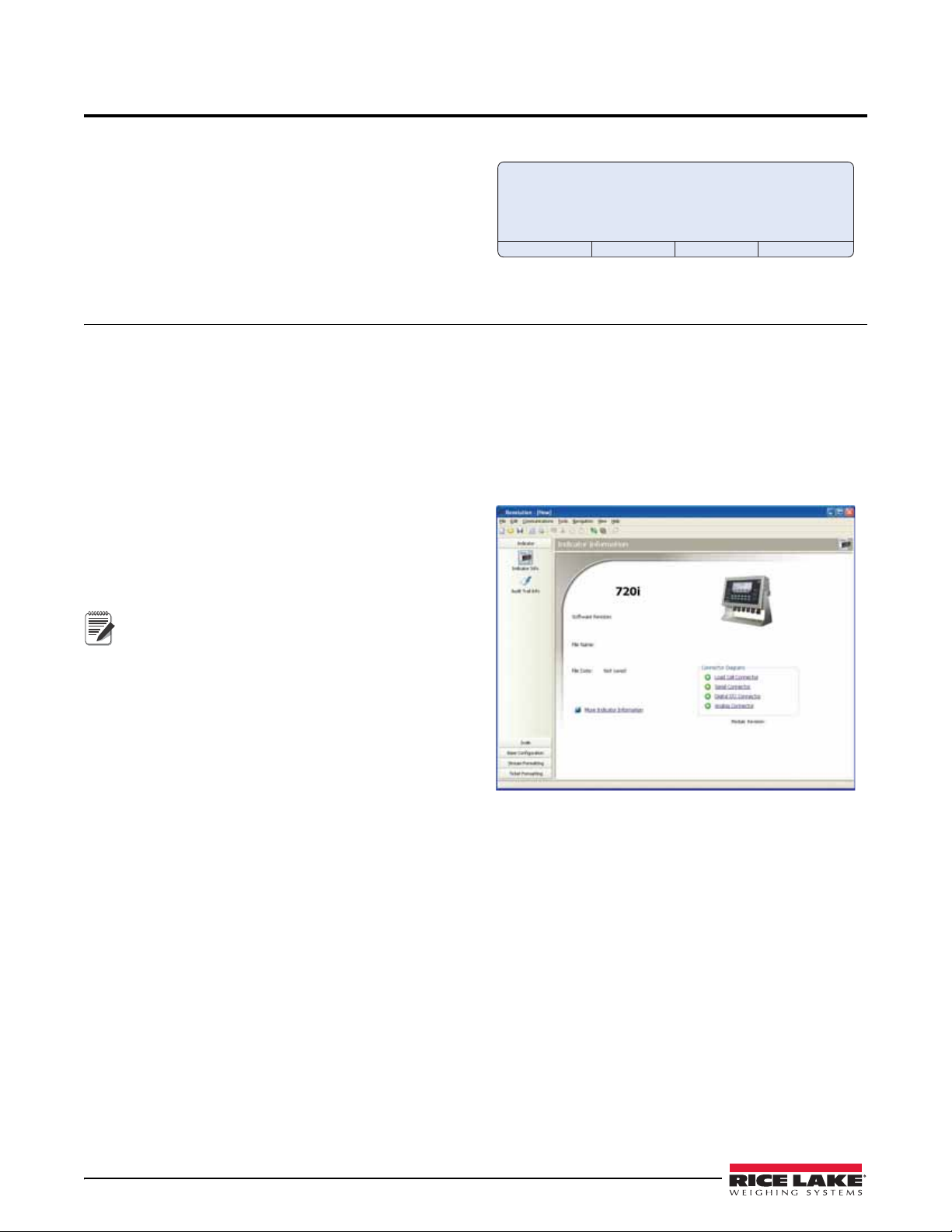
Configuration and calibration of the indica
tor can be accomplished using the Revolution II I® configuration utility,
serial commands, or the indicator front panel keys. See Section 3.1 on page 18 for information about configuration
methods.
Authorized distributors and their employees can view or download this manual from the Rice Lake
Weighing Systems distributor site at
The Operator Car
d included with this manual provides basic operating instructions for users of the 720i. Please
www.ricelake.com.
leave the Operator Card with the indicator when installation and configuration are complete.
Safety
Safety Signals
Safety Symbol Definitions
Indicates a potentially hazardous situation that, if not avoided, could result in serious injury or death, and
includes hazards that are exposed when guards are removed.
Indicates a potentially hazardous situation that, if not avoided may result in minor or moderate injury.
Indicates information about procedures that, if not observed, could result in damage to equipment or
corruption to and loss of data.
Safety Precautions
Do not operate or work on this equipment unless you have read and understand the instructions and
warnings in this Manual. Failure to follow the instructions or heed the warnings could result in injury or
death. Contact any Rice Lake Weighing Systems dealer for replacement manuals. Proper care is your
responsibility.
Some procedures described in this manual require work i
procedures are to be performed by qualified service personnel only.
nside the indicator enclosure. These
DO NOT allow minors (children) or inexperi
DO NOT operate without all shields and guards i
DO NOT step on the unit.
DO NOT jump up and down on the scale.
DO NOT use for purposes other than weight taking.
DO NOT place fingers into slots or possible pinch points.
DO NOT use any load-bearing component
DO NOT use this product if any of the components are cracked.
DO NOT exceed the rated load limit of the unit.
DO NOT make alterations or modifications to the unit.
DO NOT remove or obscure warning labels.
DO NOT use near water.
Before opening the unit, ensure the power cord is disconnected from the outl
Keep hands, feet and loose clothing
General Safety
Failure to heed may result in serious injury or death.
enced persons to operate this unit.
n place.
that is worn beyond 5% of the original dimension.
et.
away from moving parts.
Safety 1
Page 8
1.0 Introduction
The 720i is a single-channel, programmable digital
weight indicator/controller. The configuration can be
performed using the front panel, with an attached
1
®
PS/2
-type keyboard, or using the Revolution III
utility.
The 720i can be loaded with either
720i batching software. Refer to Section 8.0 on page 65
PCE software or
or Section 9.0 on page 81 for further information on
each of these software choices.
Onboard Features
Features of the basic 720i include:
• Support for a single A/D or serial scale input.
• Eight digital I/O channels
configurable as either input or output.
• Two serial ports on main board support duplex
232 up to 115200 bps. Port 2 supports RS-232
RSwith hardware handshaking; Port 4 supports
RS-232 and 20mA communications.
• Available in 115 VAC and 230 VAC North
rican and European versions.
Ame
• Configurable print formats can be defined for up to
1000 c
Revolu tion I II. These formats are used to print
haracters each using serial commands or
gross or net weights, truck in/out weights,
accumulator weights, alert messages, and header
information. Additional print formats can be
created using twenty auxiliary print formats.
• Seven truck modes to store and recall weights for
gross, tare, and
net printing. The truck register
contains fields for ID number, weight, and the
transaction time and date. Weights can be stored
permanently or erased at the end of the transaction.
720i is NTEP-certified for Classes III and III L at
The
10,000 divisions. See Section 11.15 on page 113 for
more information about additional ce
approvals.
on main board, each
rtifications and
Profibus
®
DP networks5 and ControlNet™6.
Part numbers of available option cards are listed in
Section 1.4 on page 5.
Front Panel
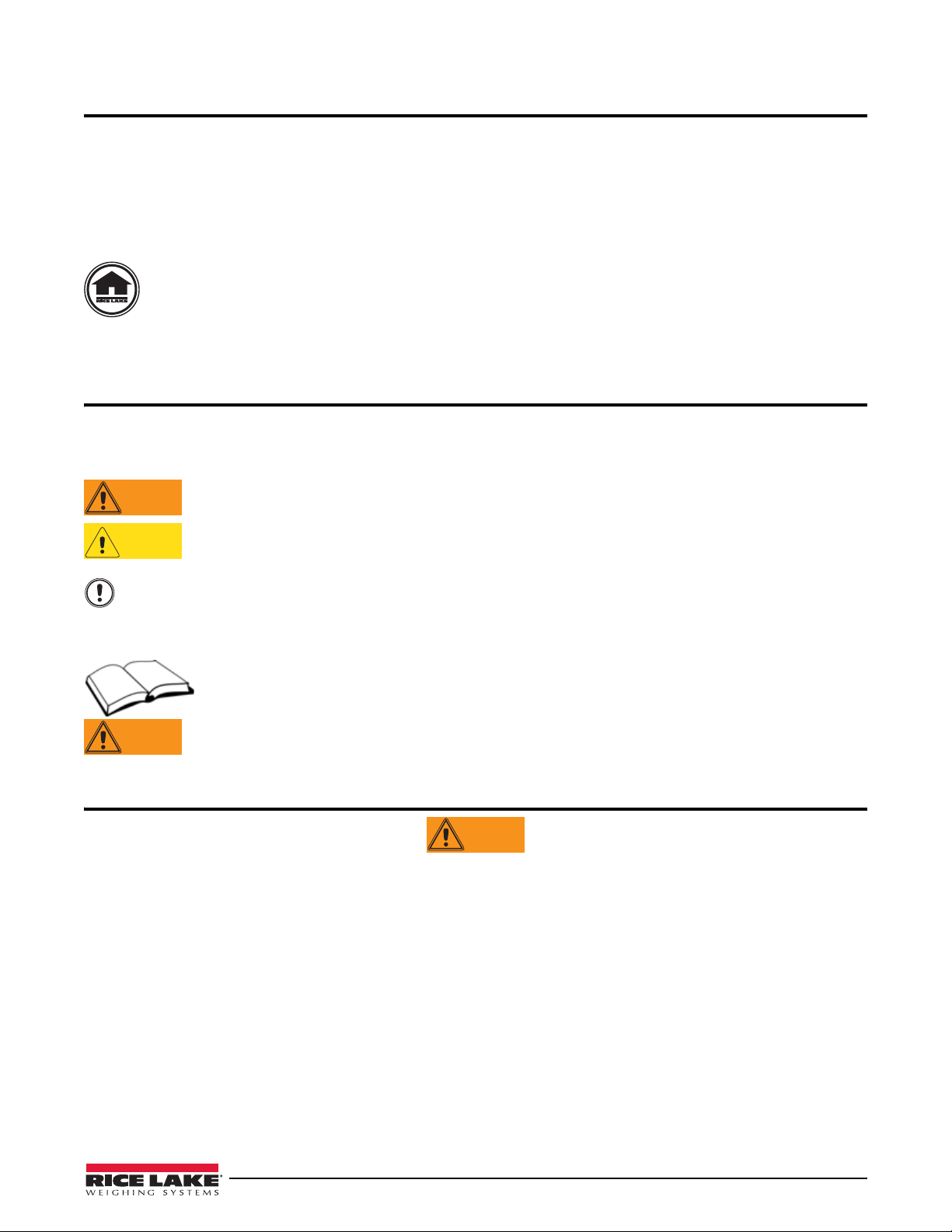
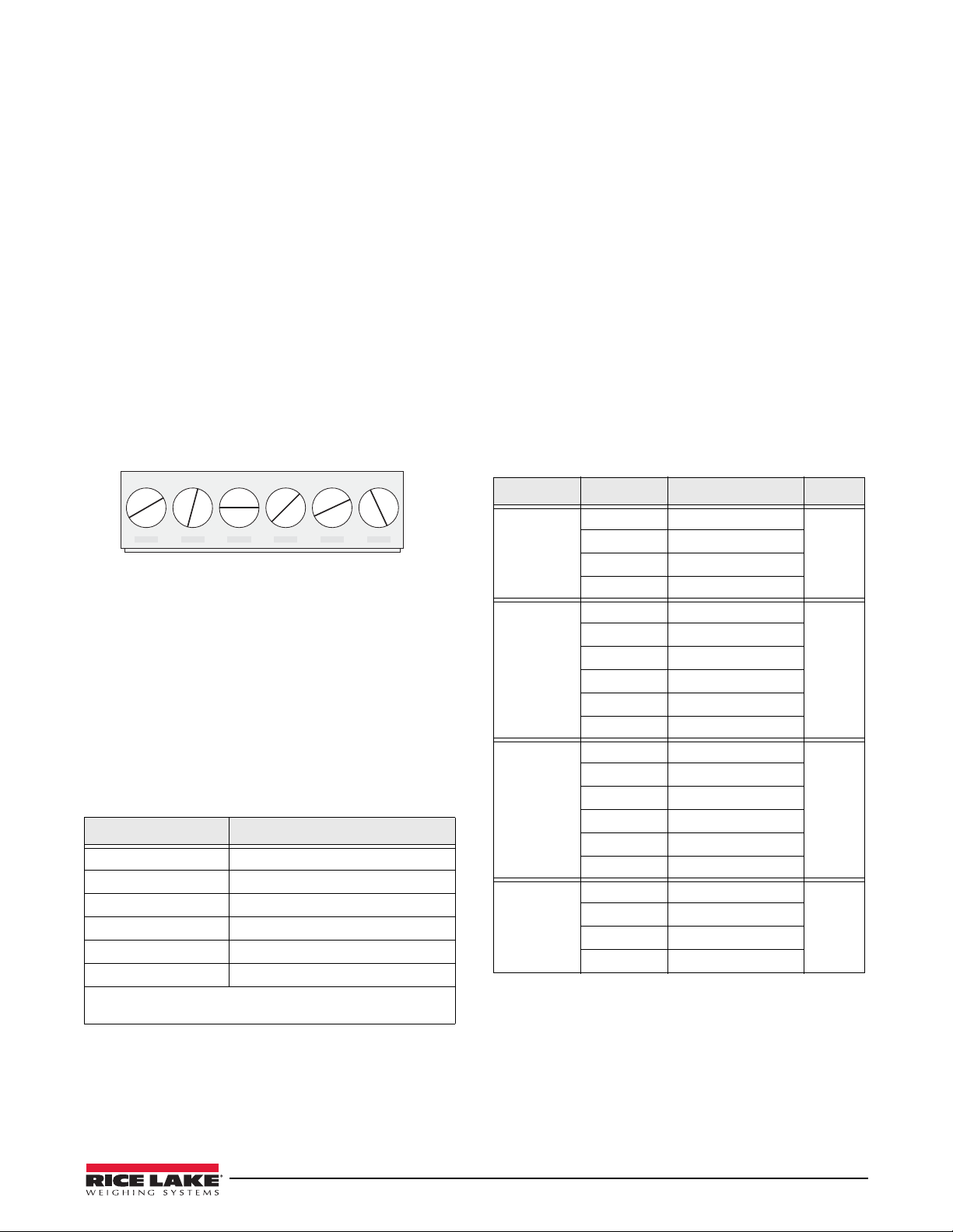
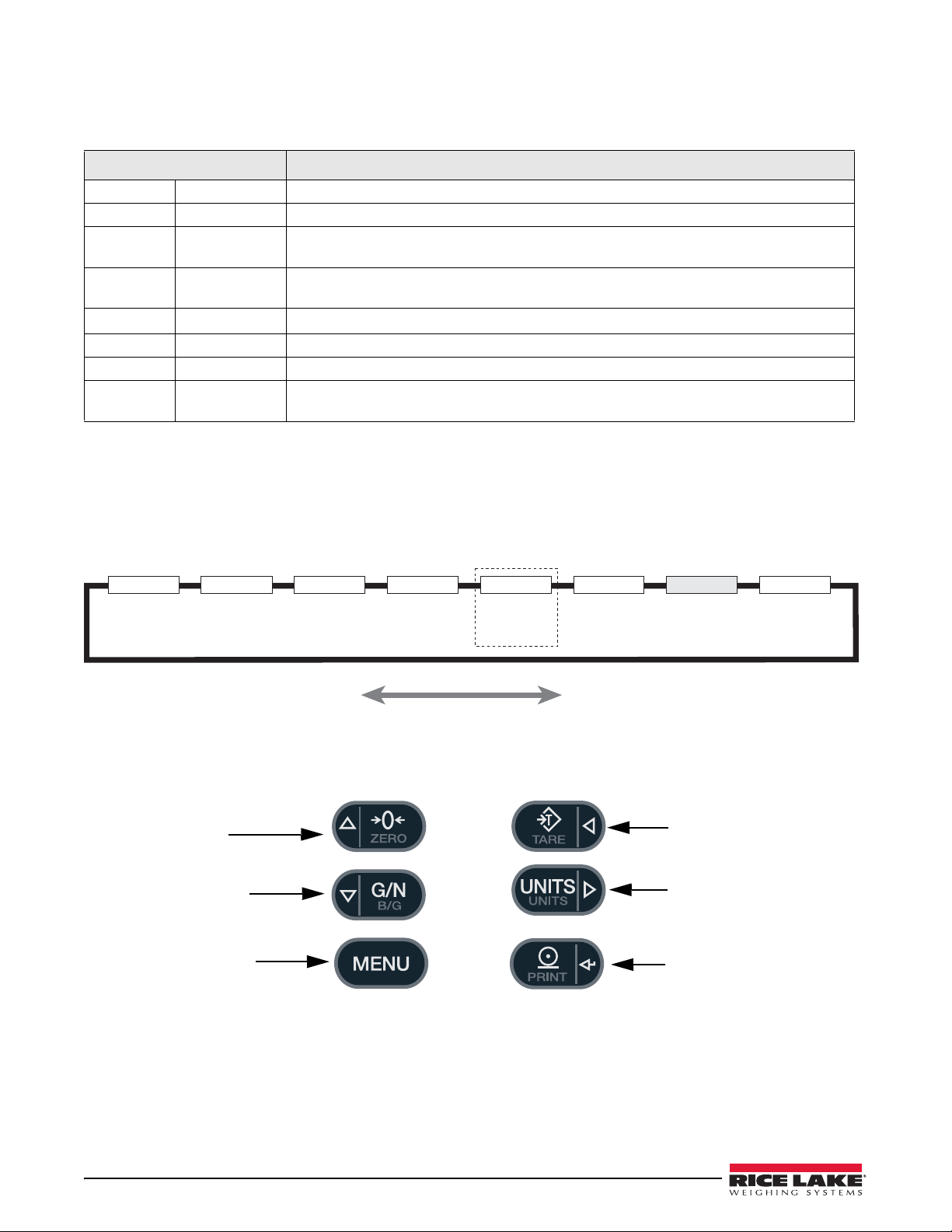
The 720i universal model front panel, shown in
Figure 1-1, consists of a 22-button keypad with an
LCD display. The keys are grouped as four
urable softkeys, four scale function/navigation
config
MENU and PRINT/Enter keys, and numeric entry
keys,
keys. The panel mount front panel is shown in
Figure 1-2.
LCD display contrast can be adjusted selecting the
Contrast Adj function from the system menu.
Figure 1-1. 720i Universal Front Panel
Option Cards
The CPU board provides one slot for installing other
option cards. Available option cards include:
• Analog output card for 0–10 VDC or 0–20 mA
trackin
• Dual-channel serial expansion card provides one
RS-48
20mA communications at up to 19200 bps.
• 24-channel digital I/O ex
• Ethernet option card
• Bus interface cards for EtherNet/IP
DeviceNet
1. PS/2® is a registered trademark of IBM Corporation.
2. EtherNet/IP™ is a trademark of ControlNe
3. DeviceNet™ is a trademark of the Open DeviceNet Vendor
2 720i Installation Manual
g of gross or net weight values.
5 port or two ports for either RS-232 or
pansion card.
3
™
, Allen-Bradley Remote I/O4,
Ltd., under license by the Open DeviceNet Vendor Association.
ciation.
Asso
t International,
2
™
Figure 1-2. 720i Panel Mount Front Panel
Enclosures
The 720i is available in universal (tilt-stand) and panel
mount enclosures. Stainless steel enclosures are rated
for NEMA 4X/IP66. This manual provides assembly
drawings and replacement parts lists for the universal
model; supplemental documentation provides
information specific to the panel mount model (See
,
Section 1.4 on page 5).
4. Allen-Bradley®, PLC®, and SLC™ are trademarks of
Allen-Bradley Company, Inc., a Rockwell International company.
5. Profibus
6. ControlNet is a trademark of C
®
is a registered trademark of Profibus Interna-
tional.
under license by the Open DeviceNet Vendor Association.
ontrolNet International, Ltd.,
Page 9

Support Applications
Note
0
Note
In addition to Revolut io n II I, the 7 20i is supported by
two Windows-based applications that extend its
capabilities for batch control and database
management. ProAction
PCEE, or Process Control
Engine Editor, provides functions similar to setpoint
configuration for
DBE, the database editor, is a tool for creating, editing,
and managing databases in the
are included on the
720i-based batch control. ProAction
720i. Both applications
720i Toolkit CD.
1.1 Operating Modes
The 720i has two modes of operation:
Setup mode
Most of the procedures described in this manual
require the indicator to be in setup mode, including
configuration and calibration.
To enter setup mode, press the
front panel, select
Configuration, then press Enter.
MENU key on the
The indicator display changes to show scale
configuration menus.
Jumper J9 (see Figure 2-3 on page 9) must be
installed to enable access to setup mode.
When configuration is complete, remove the
jumper (place the jumper on a single pin of J9)
to disable access to the configuration menus.
Normal mode
Normal mode is the weighing mode of the
indicator. The indicator displays gross, net, or tare
weights as required, using the secondary display to
indicate scale status and the type of weight value
displayed. Once configuration is complete, remove
jumper J9 and affix a legal seal to the fillister-head
screws on the indicator enclosure.
1.2 Indicator Operations
Basic 720i operations are summarized below:
Zero Scale
1. In gross mode, remove all weight from the
scale and wait for the standstill annunciator
(
2. Press the
).
ZERO key . The center of zero (
annunciator lights to indicate the scale is
zeroed.
Acquire Tare
1. Place container on scale and wait for the
standstill annunciator (
2. Press the
TARE key to acquire the tare weight
).
of the container.
3. Display shifts to net weight and shows the
N on the display.
letter
Enter Tare Value
For the universal model, use the numeric keypad to key
in the tare value, then press the
and hold the front panel
TARE key to enter the tare.
Tare softkey or press
For the panel mount model, do the following:
1. Press and hold the
GROSS/NET key for about
three seconds. When released, a zero appears.
2. Use the
Up and Down navigation keys to adjust
the value (0-9 and a decimal point) and the
Right and Left navigation keys to select the
digit.
3. Press the
Tare softkey or press and hold the
front panel TARE key for about three seconds,
then release to enter the tare.
Remove Stored Tare Value
1. Remove all weight from the scale and wait for
the standstill annunciator (
2. Press the
ZERO key). Display shifts to gross weight and
shows the word
TARE key (or, in OIML mode, the
Gross.
).
)
Display Menu
Press the MENU key to show the system menu, then use
Up or Down navigation keys to select an item from
the
the list. The menu provides access to audit trail
information, configuration, test operations, and display
contrast adjustment.
Toggle Gross/Net Mode
Press the GROSS/NET key to switch the display mode
from gross to net, or from net to gross. If a tare value
has been entered or acquired, the net value is the gross
weight minus the tare. If no tare has been entered or
acquired, the display remains in gross mode.
Gross mode is indicated by the letter
OIML mode,
N.
letter
B (brutto); net mode is indicated by the
G (gross) or, in
Toggle Units
Press the UNITS key to switch between primary,
secondary, and tertiary units.
Print Ticket
1. Wait for the standstill annunciator ( ).
2. Press the
PRINT key to send data to the serial
port.
Select Auxiliary Print Format
Any of the auxiliary print formats (1–20) can be
selected for printed output while in weighing mode.
Not available in Advance Truck Mode.
For the universal model, use the numeric keypad to key
in the print format value, then press the
the front panel
PRINT key to print using the selected
auxiliary format.
For the panel mount model, do the following:
1. Press and hold the
GROSS/NET key for about
three seconds. When released, a zero appears.
2. Use the
Up and Down navigation keys to adjust
the value (0-9 and a decimal point) and the
Print softkey or
Introduction 3
Page 10

Right and Left navigation keys to select the
Note
digit.
3. Press the
Print softkey or the front panel PRINT
key to print using the selected auxiliary format.
Accumulator Functions
The accumulator must be enabled before use. Once
enabled, weight (net weight if a tare is in the system) is
accumulated whenever a print operation is performed
using the
PRINT key, digital input, or serial command.
The scale must return to zero (net zero if a tare is in the
system) before the next accumulation.
Display Accum softkey can be configured to display
The
the current accumulator value. Printing while the
accumulator is displayed uses the ACCFMT print
format (see Section 6.0 on page 52).
Press the
CLEAR key twice to clear the accumulator.
With the panel mount version of the 720i, you
need to use CLR Accumulator DigIn Function
to clear the indicator.
1.3 Softkey Operations
Softkeys provide additional operator functions for
specific applications. Softkey assignments are listed on
the tabs shown at the bottom of the LCD display;
softkey functions are activated by pressing the arrow
keys below the softkey tabs (see Figures 1-1 and 1-2 on
page 2).
For example, to set up a
commands, do the following:
1. Place indicator in setup mode.
2. Send the following serial command:
SK#s=TimeDate
where s is th
3. Press
SaveExit (or send the KSAVEEXIT serial
command). The new softkey will appear in the
position specified by s.
4. Press the
TimeDate softkey. Use the Up/Down
navigation keys to adjust the time and date
value; use the
fields. Time and date fields are presented in the
following order:
HOUR>MIN>[AM/PM]>MONTH>DAY>YEAR
When done, press
mode.
The particular set of softkeys sh
be set using serial commands or
TimeDate softkey using serial
e softkey position.
Left/Right keys to move between
Enter to return to weighing
own on the display can
Revolution III.
Softkey Description
None Not Configured, no softkeys wil
after a none key.
<blank> Empty Key, allows for a space/blank
tween other softkeys.
be
Time/Date Displays current time and date; allows
and date change.
time
Display Tare Displays tare value for the current scale
Display Accum Displays accumulator value, if enabled, for
ent scale.
the curr
Display ROC Displays rate-of-change value, if enabled,
r the current scale.
fo
***Weigh In Allows truck ID entry; generates
ticket for truck weighing applications.
***Weigh Out Allows truck ID entry; generates weig
ticket for truck weighing applications.
***Truck Regs Displays truck register; allows deletion of
ndividual or all entries. Truck register can
i
be printed by pressing the PRINT key
e truck register is displayed.
while th
Alibi Allows previous print transactions to be
ecalled and reprinted.
r
SKUD 1-10 User-programmable keys; defined by
l appear
weigh-in
h-out
PCEE.
**Setpoint Displays a menu of configured setpoints;
allows display and change of some
setpoint parameters.
**Batch Start Starts a configured batch.
Stop Stops a running batch and turns off all
**Batch
associated digital outputs. Requires a
batch start to resume processing.
ch Pause Pauses a running batch. (Same as stop,
**Bat
but digital outputs, if on, are not turned
off.)
**Batch Reset Stops a batch and resets it to the first
batch step.
*Weigh Start the Weigh-In and Weigh-Out
ocedure.
Pr
*Reports Select which report to print. There are four
sub menus under
Summary, Daily, Detail, and Code List.
*Management Add and remove materials, customers,
nd source IDs and names.
a
More… For applications with more than three
fined softkeys, the More… key is
de
automatically assigned to the fourth
softkey position. Press More… to toggle
tween groups of softkeys.
be
* Advance Truck Mode only
720i Batching Version software only
**
*** Truck Modes 1-6 only
the Reports softkey:
Table 1-1. Configurable Softkeys
4 720i Installation Manual
Page 11

1.4 System Configurations and Options
Table 1-2 lists the 720i system models and part
numbers. All models inclu
option card slot. The
cannot be upgraded to a multi-channel A/D.
System Model Model PNs
Universal (tilt stand) model, 115/230 VAC
with PCE softwar
Universal (tilt stand) model, 115/230 VAC,
opean, CEE 7/7 power cord with PCE
Eur
software
Panel mount model, 115/230 VAC (power
cor
d sold separately), with PCE software
Universal (tilt stand) model, 115/230 VAC
h 720i Batch software
wit
Universal (tilt stand) model, 115/230 VAC,
Eur
opean, CEE 7/7 power cord with 720i
Batch software
Panel mount model, 115/230 VAC (power
d sold separately), with 720i Batch
cor
software
Table 1-2. Part Numbers for 720i Models
e
Option Cards
Table 1-3 lists the available 720i option cards. Most of
the listed option cards are installed in
card slot, J12. USB, Ethernet, and fiber-optic interface
cards are installed in connector J11.
Option Card PN
Single-channel analog output card 67602
Dual serial port expansion card 67604
24-channel digital I/O expansion card 67601
Ethernet communications card 71986
EtherNet/IP communications card 87803
DeviceNet interface card 68541
Allen-Bradley Remote I/O interface card 68539
Profibus DP interface card 68540
USB interface card 93245
Fiber-optic interface card 96736
de CPU board with one
720i is a single scale unit and
101230
103459
101229
115447
115448
115449
the expansion
Relay Options
Relay racks are available for all 720i systems. Relays
require an external enclosure for the relays. Consult
factory for details.
DC Power Supplies
Two DC power supplies are available for mobile 720i
applications:
PN 97474, 9–36 VDC supply
PN 99480, 10–60 VDC supply
Consult factory for more information.
1.5 Summary of Changes
Updates to this manual include the following:
Version 1.03
• MINNEG and MAXNEG parameters have
been added to the ALGOUT menu (see
Section 3.2.6 on page 45) to support tracking
of negative weight values.
•Added Section 9.0 on page 81 on ProAction
PCEE information.
• Added print token for Al
Version 1.04
• Upda t ed the analog menu.
•Added Section 8.0 on page 65 on Setpoints
(Version 2.00)
•Batching (
720i batching Version 1.00).
• Updated Alibi Tracking Section 11.12 on
page 110.
Version 2.00
• Added Advance Mode Section 7.6 on page 59.
• Updated FEATURE menu Figure 3-13 on
page 37 to include Advance Mode.
•Batching (
720i batching Version 1.01).
ibi Numbering <AN>.
Table 1-3. Part Numbers for 720i Option Cards
Introduction 5
Page 12
2.0 Installation
CAUTION
WARNING
Insulated cable
Foil (silver side out)
Grounding clamp
Shield wire (cut)
Length of foil before folding
back on cable insulation
Cut insulation here
for foil-shielded cables
Braid
Cut insulation here
for braided cables
NOTE: Install lockwashers
first, against backplate,
under grounding clamp
This section describes procedures for connecting load
cell, digital I/O, and serial communications cables to
720i indicator. Assembly drawings and replacement
the
parts lists for the universal model are included for the
service technician. See Section 11.13 on page 111 for
dimension drawings.
• Use a wrist strap to ground yourself and
protect components from electrostatic
discharge (ESD) when working inside the
indicator enclosure.
• This unit uses double pole/neutral fusing
hich could create an electric shock hazard.
w
Procedures requiring work inside the indicator
must be performed by qualified service
personnel only.
• The supply cord serves as the power
connect for the 720i. The power outlet
dis
supplying the indicator must be installed near
the unit and be easily accessible.
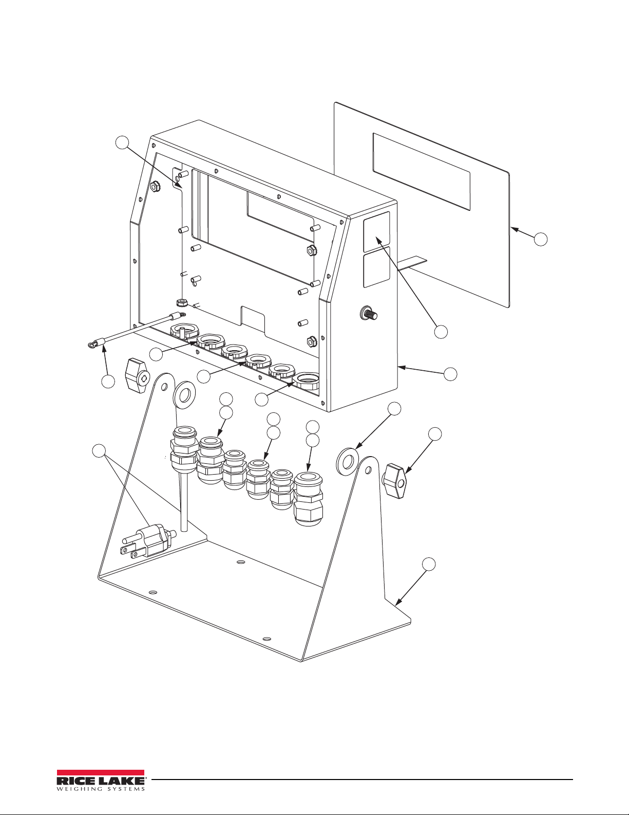
2.1 Unpacking and Assembly
Immediately after unpacking, visually inspect the 720i
to ensure all components are included and undamaged.
The shipping carton should contain the indicator, this
manual, and a parts kit. If any parts were damaged in
shipment, notify Rice Lake Weighing Systems and the
shipper immediately.
See Section 2.9 on page 11 for parts kit contents.
2.3.1 Cable Grounding
Except for the power cord, all cables routed through the
cord grips should be grounded against the indicator
enclosure. Do the following to ground shielded cables:
• Use the lock washers, clam
provided in the parts kit to install grounding
clamps on the enclosure studs adjacent to cord
grips. Install grounding clamps only for cord
grips that will be used; do not tighten nuts.
• Route cables through cord grips and grounding
clamps to
determine cable lengths required to
reach cable connectors. Mark cables to remove
insulation and shield as described below:
• F or cables with foil shielding, strip insulation
and foil from
the cable half an inch (13 mm)
past the grounding clamp (see Figure 2-1).
Fold the foil shield back on the c
cable passes through the clamp. Ensure silver
(conductive) side of foil is turned outward for
contact with the grounding clamp.
• For cables with braided shielding, strip cable
insulation
and braided shield from a point just
past the grounding clamp. Strip another half
inch (13 mm) of insulation only to expose the
braid where the cable passes through the clamp
(see Figure 2-1).
ps, and kep nuts
able where the
2.2 Enclosure Disassembly
The indicator enclosure must be opened to install
option cards and to connect cables for installed option
cards.
Ensure power to the indicator is disconnected, then
place the indicator face-down on an antistatic work
mat. Remove the screws that hold the backplate to the
enclosure body, then lift the backplate away from the
enclosure and set it aside.
2.3 Cable Connections
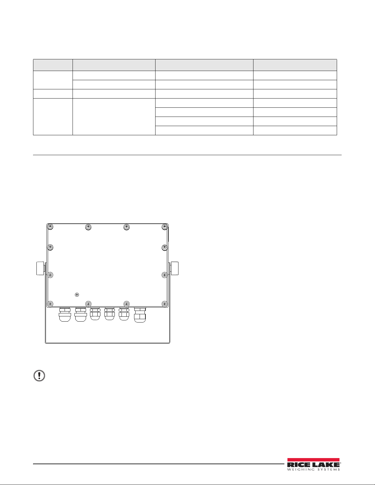
The universal model of the 720i provides six cord grips
for cabling into the indicator: one for the power cord,
five to accommodate other cabling. Install plugs in all
unused cord grips to prevent moisture from entering
the enclosure.
6 720i Installation Manual
The 720i has no on/off switch. Before
opening the unit, ensure the power cord is
di
sconnected from the power outlet.
Figure 2-1. Grounding Clamp Attachment for Foil-Shielded
and Braided Cabling
Page 13
• For load cell cables, cut the shield wire just
J1
LOAD CELL CONNECTOR
+SIG
–SIG
+SENS
–SENS
+EXC
–EXC
past the grounding clamp. Shield wire function
is provided by contact between the cable shield
and the grounding clamp.
• Route stripped cables through cord grips and
clamps. Ensure shields contact grounding
clamps as shown in Figure 2-1. Tighten
grounding clamp nuts.
• Finish installation using cable ties to secure
cables inside
of indicator enclosure.
2.3.2 Load Cells
To attach cable from a load cell or junction box to the
720i, route the cable through the cord grip and ground
the shield wire as described in Section 2.3.1 on page 6.
Next, remove load cell connect or J1 from C PU board.
ire the load cell cable from the load cell or junction
W
box to the connector as shown in Table 2-1.
Figure 2-2. Load Cell Connector
If using 6-wire load cell cable (with sense wires),
remove jumpers JP1 and JP2 before reinstalling
connector J1. For 4-wire installation, leave jumpers
JP1 and JP2 on.
When connections are complete, reinstall load cell
connector on the CPU board heade
ties to secure the load cell cable to the inside of the
enclosure.
J1 Connector Pin Function
1 +SIG
2 –SIG
3 +SENSE
4 –SENSE
5 +EXC
6 –EXC
• For 6-wire load cell connections,
and JP2.
Table 2-1. Load Cell Connector Pin Assignments
r and use two cable
remove jumpers JP1
2.3.3 Serial Communications
Communications ports on the 720i CPU board support
PS/2-type remote keyboard, full duplex RS-232, and
20 mA output communications at up to 115200 bps.
Optional communications cards support USB,
Ethernet, and fiber-optic connections to the
To attach serial communications ca
bles, route the cable
through the cord grip and ground the shield wire as
described in Section 2.3.1 on page 6. Remove the serial
connector from the CPU board and wire to the
connec
tor. Once cables are attached, plug the connector
into the header on the board. Use cable ties to secure
serial cables to the inside of the enclosure.
Table 2-2 shows the pin assignments for Ports 1, 2, and
4. Port 1 supports remote keyboard attachment of PS/
2-type perso
nal computer keyboards (see Section 11.9
on page 109 for information about the PS/2 keyboard
interface.) Port 3 uses connector J4 to provide a
edicated display port for both universal and pan el
d
mount versions of the
Connector Pin Signal Port
J3 1 CLK 1
J2 1 GND 2
J4 1 RS-422/485 Y 3
J5 1 GND 4
Table 2-2. Serial Port Pin Assignments
720i.
2 +5V
3 GND
4 DATA
2 RS-232 RxD
3 RS-232 TxD
4 RS-232 RTS
5 RS-232 CTS
6 GND
2 RS-422/485 Z
3 RS-422/485 B
4 RS-422/485 A
5 +6V
6 GND
2 RS-232 RxD
3 RS-232 TxD
4 20mA OUT
Serial ports are configured using the SERIAL menu.
See Section 3.2.2 on page 33 for configuration
information.
720i.
Installation 7
Page 14
An optional dual-channel serial communications
Note
Note
CAUTION
expansion card, PN 67604, is also available. The serial
expansion card provides two additional serial ports,
assigned as port numbers 7 and 8. One port on the
serial expansion card supports four-wire RS-485
communications. Both ports on the expansion card can
support RS-232 or 20mA connections.
Installation of option cards in connector J11
requires removal of the PORT2/OPTI port
lection jumper (see Figure 2-3 on page 9).
se
Install the jumper to enable RS-232
communications through connector J2;
remove the jumper to enable an USB,
fiber-optic, or Ethernet option card installed in
connector J11.
See the communications interface card installation
instructions for more information.
2.3.4 Digital I/O
Digital inputs can be set to provide many indicator
functions, including all keypad functions. Digital
inputs are active low (0 VDC), inactive high (5 VDC).
Digital outputs are typically used to control rel
drive other equipment. Outputs are designed to sink,
rather than source, switching current. Each output is a
normally open collector circuit, capable of sinking 24
mA when active. Digital outputs are wired to switch
relays when the digital output is active (low, 0 VDC)
with reference to a 5 VDC supply.
Table 2-3 shows the pin assignments for connector J6.
J6 Pin J6 Signal
1 +5 VDC
2 GND
3 DIO 1
4 DIO 2
5 DIO 3
6 DIO 4
7 DIO 5
8 DIO 6
9 DIO 7
10 DIO 8
Table 2-3. J6 Pin Assignments (Digital I/O)
Digital inputs and outputs are configured using the
DIG I/O menu. See Section 3.2.5 on page 43 for
configuration information.
An optional 24-channel digital I/O exp
ansion card, PN
67601, is available for applications requiring more
digital I/O channels.
A digital I/O point can be configured to count
active pulse inputs by setting the bit to INPUT
(DIG I/O menu) and using
bit. However, the fastest pulse rate that can be
counted using a digital input is 10Hz (10 pulses
per second).
PCEE to monitor the
ays that
2.3.5 Detached Display Module (DDM)
Table 2-4 shows the connections between connector J4
on the
720i CPU board and connector J3 (Com 1) on
the detached display module (DDM) board. See board
diagrams in Figures 2-3 and 2-4, on page 9.
DDM Com 1
J3 Connector
Pin Signal Pin Signal
1 A 1 Y
2 B 2 Z
3 Z 3 B
4 Y 4 A
5 +6V 5 +6V
6 GND 6 GND
Table 2-4. CPU Board—DDM Connections
CPU Board
J4 Connector
2.4 Installing Option Cards
Each option card is shipped with installation
instructions specific to that card. The general procedure
for all option cards is as follows:
Option cards are not hot-pluggable.
Disconnect power to the
installing option cards.
1. Disconnect power to the indicator. Remove
backplate as described in Section 2.2 on
page 6.
2. Carefully align the option card co
connector J12 or J11 on the CPU board (see
Figure 2-3 on page 9). Press down to seat the
option card in the CPU board connector.
3. Use the screws provided in the option kit to
secure
the other end of the option card to the
threaded standoffs on the CPU board (see
Figure 2-3).
4. Make connections to the option card as
required. U
se cable ties to secure loose cables
inside the enclosure. When installation is
complete, reassemble the enclosure as
described in Section 2.6 on page 10.
720i automatically recognizes all installed option
The
cards when the unit is powered on. No
hardware-specific configuration is required to identify
the newly installed card to the system.
720i before
nnector with
8 720i Installation Manual
Page 15
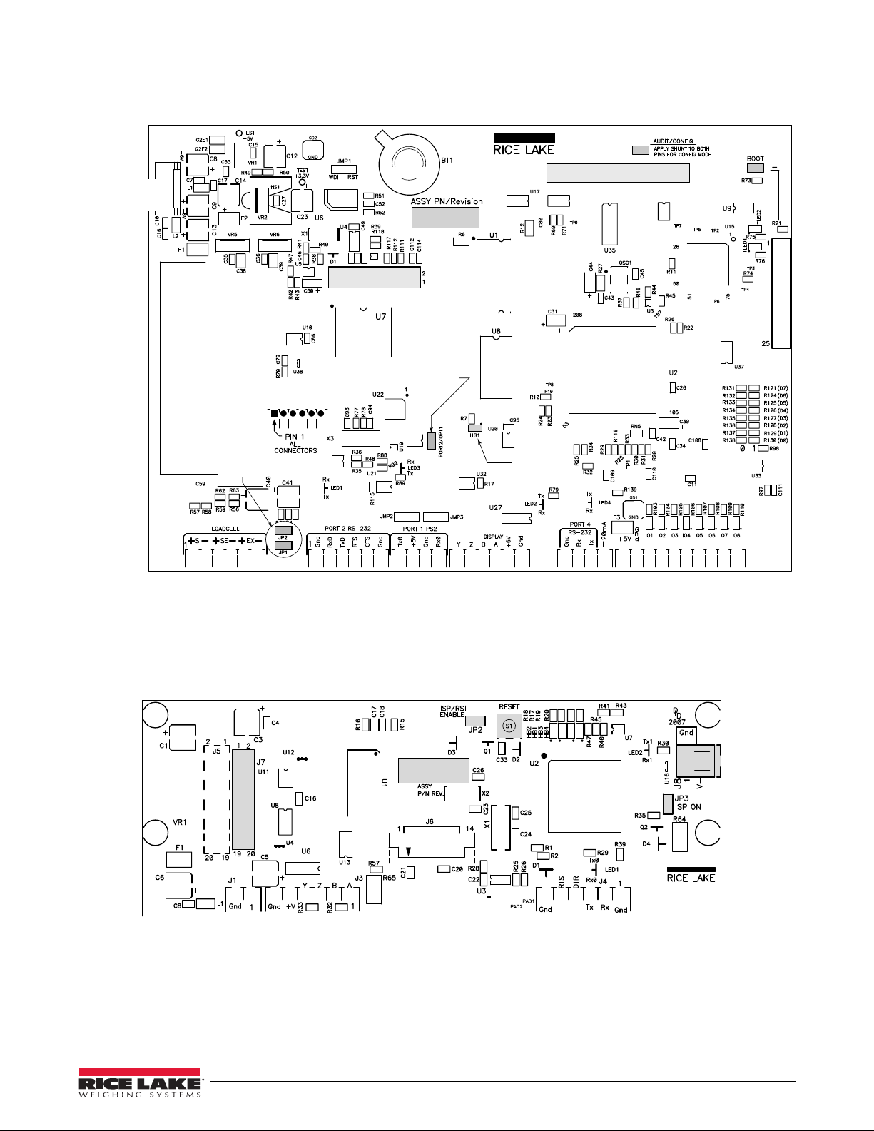
J5
SERIAL PORT 4
J4
SERIAL PORT 3
DISPLAY
J3
SERIAL PORT 1
PS/2
J2
SERIAL PORT 2
J1
LOAD CELL CONNECTOR
BATTERY
LOAD CELL SENSE
JUMPERS
J6
DIGITAL I/O
J12
EXPANSION CARD SLOT
J11
COMMUNICATIONS
OPTION CARD SLOT
J9
SW1
JUMPER ON TO ENABLE J2,
OFF TO ENABLE J11
HEARTBEAT
LED
J10
POWER SUPPLY
CONNECTOR
J7
J8
COM 1 COM 0
CPU Interface Port
Programming Port
Figure 2-3. 720i CPU Board
Figure 2-4. 720i Display Board
Installation 9
Page 16
2.5 Slot Assignments
5PSRVFCBDLQMBUFTDSFXT
UPJOMC/N
Important
Table 2-5 lists the slot numbers, CPU board connectors, and configuration assignments made for both onboard and
expansion card functions in the
Slot Number Connector Function Configured As
0
1
2
Connector J6 Onboard digital I/O Slot 0, bits 1–8
Connectors J3, J2, J5 Onboard serial communications Ports 1, 2, 4
Connector J1 Onboard single-channel A/D Channel 1
Connectors J12 (expansion card
slot) and J11(communications
option card slot)
720i. See Figure 2-3 for connector locations.
Dual-channel serial expansion card Ports 7–8
Digital I/O expansion card Slot 2, bits 1–24
Analog output card Analog 2
Bus communications cards Bus Option 2
Table 2-5. 720i Slot Assignments
2.6 Enclosure Reassembly
Once cabling is complete, position the backplate over
the enclosure and reinstall the backplate screws. Use
the torque pattern shown in Figure 2-5 to prevent
distorting the backplate gasket. Torque screws to 15
in-lb (1.7
N-m).
2.7 CPU Board Removal
If you must remove the 720i CPU board, use the
following procedure:
1. Disconnect power to the indicator. Remove
backplate as describe
page 6.
2. Unplug connectors for power to the board,
serial co
mmunications, digital I/O, and any
installed option cards.
3. Remove any installed option cards.
4. Remove the five phillips head sc
kep nut from the CPU board.
5. Remove CPU board from the enclosure. If
necessary
, cut cable ties to shift cables out of
the way.
To replace the CPU board, reverse the above
procedure. Be sure to reinstall cable ties to secure all
bles inside the indicator enclosure.
ca
d in Section 2.2 on
rews and the
Figure 2-5. 720i Enclosure Backplate
10 720i Installation Manual
Torqued screws may become less tight as
the gasket is compressed during torque
pattern, therefore a second torque is
required using the same pattern and
torque value.
Page 17

2.8 Battery Replacement
WARNING
The lithium battery on the CPU board maintains the
real-time clock and protects data stored in the system
RAM when the indicator is not connected to AC power.
Data protected by the CPU boar
and date, truck and tare memory, and onboard database
information.
Revolut ion I II
Use
™
to store a copy of the indicator
configuration on a PC before attempting battery
replacement. If any data is lost, the indicator
configuration can be restored from the PC.
Watch for the low battery warning on the LCD display
and periodically check
the battery voltage on both the
CPU board and on any installed memory option cards.
Batteries should be replaced when the indicator low
battery warning comes on, or when battery voltage falls
d battery includes time
Replacement Procedure
For best results, replace the battery while in weigh
mode and with AC power applied. Use care not to
bend the battery retaining spring.
If the battery must be replaced with power removed, do
ollowing immediately after restoring power:
the f
1. Place indicator in setup mode.
2. Go to the Version menu and press the
RSConfig
softkey. If connected using Revolution III,
configuration can be reset by using monitor
mode to enter the RESETCONFIGURATION
command followed by the RS command.
See Figure 2-3 on page 9 for CPU board battery
location and orientation (positive side up).
Risk of explosion if battery is replaced
with incorrect type. Dispose of batteries
per manufacturer instruction.
to 2.2 VDC. Life expectancy of the battery is ten years.
2.9 Replacement Parts and Assembly Drawings
2.9.1 Universal Model
Table 2-6 lists replacement parts and parts kit contents for the 720i universal enclosure model, including all parts
referenced in Figures 2-6 through 2-8.
Ref Number PN Description (Quantity) See Figure
1 101257 Switch panel membrane, universal (1) 2-6
2 53308 Model/serial number label (1)
3 101263 Enclosure, universal (1)
4 103988 Tilt stand washer
5 103610 Tilt stand knobs (2),
6 67531 Tilt stand (1)
7 15628 Cord grip, 1/2 NPT (1)
8 15626 Cord grips, PG9 (3)
9 15630 Lock nut for 1/2 NPT cord grip (1)
10 68600 Cord grip, PG11 (1)
11 15627 Lock nuts, PCN9 (3)
12 68601 Lock nut, PG11 (1)
13 45043 Ground wire, 4 in w/ No. 8 eye connector (1)
14 102887 Display board assembly, universal (1) 2-7
15 85202 Power cord assembly, 115 VAC and 230 VAC North American units (1) 2-6
85203 Power cord assembly, 230 V
16 67885 Standoffs, M-F, 4-40NC x 3/4 (2) 2-7
17 14618 Kep nuts, 4-40NC hex (3)
18 103443 CPU board mounting strip (1)
19 106788
20 102376 Backplate gasket, universal (1) 2-7
21 75062 Sealing washers (4)*
22 14862 Machine screws, 8-32NC x 3/8 (4)*
720i CPU board (PCE Version) (1)
s (2), in parts kit
in parts kit
AC European units (1) —
Table 2-6. Universal Model Replacement Parts
Installation 11
Page 18

Ref Number PN Description (Quantity) See Figure
23 14626 Kep nuts, 8-32NC (7)* 2-8
24 53307 Label (1) 2-7
25 69291 3V Lithium coin battery
26 103989 Standoffs, F-F, 4-40 x 1.06 (3)
27 14825 Machine screws, 4-40NC x 1/4 (18)
28 102888 LCD display module, 240x64, universal (1)
29 16861 High voltage warning label (1)
30 67796 Power supply cable assembly, to CPU board (1)
31 67613 Power supply, ±6VDC, 25W (1)
32 103442 Power supply bracket (1)
33 103936 Component plate (1) 2-6
35 16892 Ground/Earth label (1) 2-8
36 15134 Lock washers, No. 8, Type A (3)
37 30376 Nylon seal ring for 1/2 NPT cord grip (1) 2-6
38 30375 Nylon seal rings for PG9 cord grips (3)
39 68599 Nylon seal ring for PG11 cord grip (1)
40 102377 Enclosure backplate, universal (1) 2-7
— 103458 Ribbon cable assembly, 7 in, 20-pin female, universal (1) —
— 103609 Cable assembly, CPU-to-display, universal (1) —
* Additional parts included in parts kit.
Universal Model Parts Kit Contents
104033
103988 Tilt stand washers (2)
103610 Tilt stand knobs (2)
42149 Rubber feet for tilt stand (4)
30623 Machine screws, 8-32NC x 7/16 (3)
14626 Kep nuts, 8-32NC (4)
14862 Machine screws, 8-32NC x 3/8 (5)
15134 Lock washers, No. 8, Type A (4)
15631 Cable ties (5)
15665 Reducing gland for 1/2 NPT cord grip (1)
19538 Cord grip plugs (4)
53075 Cable shield ground clamps (4)
75062 Sealing washers (8)
71344 10-position screw terminal for J6 (1)
76513 4-position screw terminals for J3 and J5 (2)
76514 6-position screw terminals for J1, J2 and J4 (3)
94422 Capacity label (1)
720i Software Tool Kit CD (1)
12 720i Installation Manual
Table 2-6. Universal Model Replacement Parts (Continued)
Page 19
33
13
12
11
9
39
10
38
8
37
7
15
3
4
5
6
2
1
Figure 2-6. 720i Universal Model Assembly, Enclosure and Tilt Stand
Installation 13
Page 20
25
26
27
28
29
30
31
32
14
16
18
17
19
40
24
21
22
20
From Power Supply
Ground wire (13)
to backplate (22)
36
23
35
Ground wire from
power cord (15)
Grounding Stack
14 720i Installation Manual
Figure 2-7. 720i Universal Model, CPU Board and Backplate
Figure 2-8. 720i Universal Model, Grounding Detail
Page 21

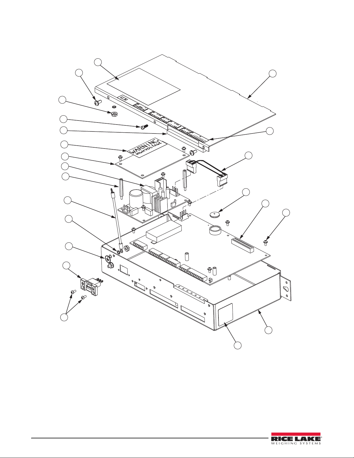
2.9.2 Panel Mount Controller
Table 2-7 lists replacement parts and parts kit contents for the 720i panel mount controller, including all parts
referenced in Figure 2-9 on page 16.
Ref Number PN Description (Quantity)
1 103314 Panel mount controller cover (1)
2 103677 Panel mount controller connector label (1)
3 101263 Enclosure, universal (1)
3 67796 Power supply cable assembly
4 69291 3V Lithium coin battery
5 106788
6 14822 Machine screws, 4-40NC x 1/4 (10)
7 101264 Panel mount controller enclosure (1)
8 53308 Labels (2)
9 14825 Machine screws, 4-40NC x 1/4 (2)
10 103681 AC feed-through header (1)
11 16892 Ground/Earth label (1)
12 15601 Ground wire, 6 in w/ No. 8 eye
13 67885 Standoffs, M-F 4-40NC x 1.25 (2)
14 67613 Power supply, ±6VDC, 25W (1)
15 85494 Power supply cover (1)
16 16861 High voltage warning label (1)
17 54206 Machine screw, fillister h
18 14626 Kep nuts, 8-32NC hex (2)
19 14839 Machine screws, 6-32NC x 1/4 (2)
20 53307 Label (1)
21 15134 Lock washers, No. 8, Type A (2)
22 71698
720i CPU board assembly (PCE Version) (1)
Polyurethane foam strip (1)
, to CPU board (1)
connector (1)
ead, 6-32NC x 3/8 (1)
Panel Mount Controller Parts Kit Contents
104033
15888 3-position terminal block (1)
71344 10-position screw terminal for J6 (1)
76513 4-position screw terminals for J3 and J5 (2)
76514 6-position screw terminals for J1, J2 and J4 (3)
14626 Kep nut, 8-32NC hex (1)
14862 Machine screws, 8-32NC x 3/8 (2)
15134 Lock washers, No. 8 Type A (7)
15694 No. 8 crimp connector (1)
53075 Cable shield ground clamps (4)
30623 Machine screws, fillister head, 8-32NC x 7/16 (2)
94422 Capacity label (1)
720i Software Toolkit CD (1)
Table 2-7. Panel Mount Controller Replacement Parts
Installation 15
Page 22
20
19
18
17
22
16
15
14
13
12
21
11
10
9
8
7
6
5
4
3
1
2
Figure 2-9. Panel Mount Controller Assembly
16 720i Installation Manual
Page 23
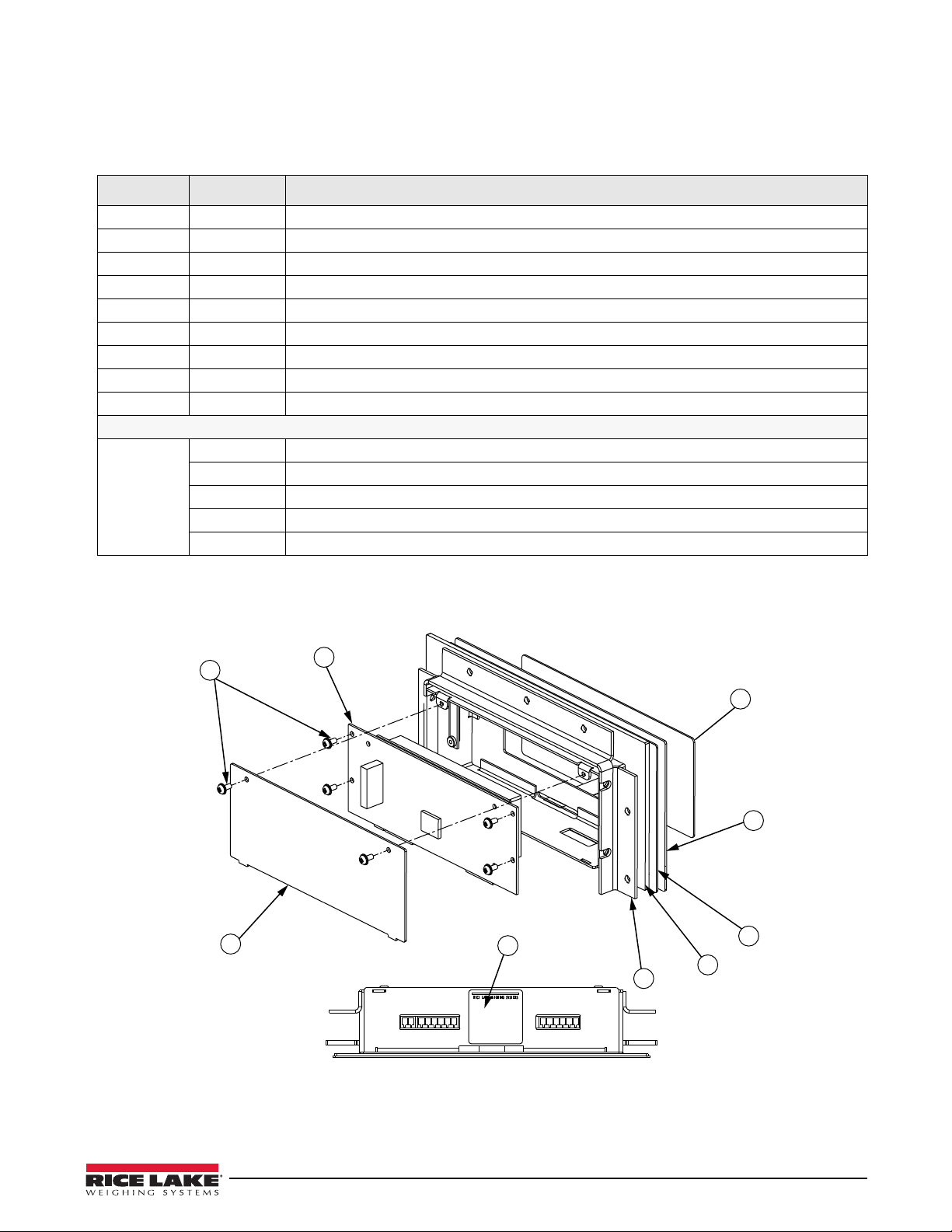
2.9.3 Panel Mount Display
6
5
4
1
2
3
9
8
7
Table 2-8 lists replacement parts and parts kit contents for the 720i panel mount remote display unit, including all
parts referenced in Figure 2-10.
Ref Number PN Description (Quantity)
1 101256 Switch panel membrane, panel
2 101265 Faceplate, panel mount display (1)
3 68719 Faceplate gasket, panel mount display (1)
4 102605 Backplate, panel mount display
5 14822 Machine screws, 4-40NC x 1/4 (6)
6 101239 Remote display board assembly (1)
7 53308 Label (1)
8 69787 Clinching bracket (1)
9 82426
Panel Mount Remote Display Parts Kit Contents
76514 6-position screw terminal (1)
94422 Capacity label (1)
53075 Cable shield ground clamp (1)
71522 Machine screws, 8-32NC x 1/4 (4)
82425 Machine screws, 10-32NF x 1.50 (7)
Backing plate, panel mount display (1)
Table 2-8. Panel Mount Display Unit Replacement Parts
mount display (1)
(1)
Figure 2-10. 720i Panel Mount Display Assembly
Installation 17
Page 24
3.0 Configuration
Menu:
Save & Exit
Audit Trail
Configuration
Test Operations
Contrast Adj.
Exit
Note
To configure the 720i indicator, press the MENU key on
the front panel (only if jumper J9 is installed), press the
Down key to select Configuration, then press Enter.
Detailed descriptions of the configuration menus are
provided in Section 3.2 on page 20.
When configuration is complete, press the
softkey to exit setup mode. Save & Exit writes all
parameter changes to NV RAM before returning to
normal mode.
3.1 Configuration Methods
The 720i indicator can be configured by using the front
panel keys to navigate through a series of configuration
menus or by sending commands or configuration data
to an indicator serial port. Configuration using the
menus is described in Section 3.1.3 on page 19.
Configuration using the serial port can be
complished using either the serial command set
ac
described in Section 10.1 on page 86 or the
® configuration utility and there are two software
III
modules available:
720i PCE
•
•
720i Batching
Some configuration parameters cannot be
accessed through the configuration menus.
Revolution III provides the most complete
and efficient configuration interface for the
720i.
Save & Exit
Revolution
Figure 3-1. 720i Menu Display
2. With both indicator and PC powered off,
connect
the PC serial port to the RS-232 pins
on the indicator serial port or to the optional
USB communications card.
3. Power up the PC and the indicator. To enter
up mode, see “Configuration” above.
set
4. Start the
Revolution II I program.
3.1.1 Revolution Configuration
The Revol uti on II I configuration utility provides the
preferred method for configuring the
Revolution III runs on a personal computer to set
configuration parameters for the indicator. When
Revolutio n III configuration is complete, configuration
data is downloaded to the indicator.
Revolution III supports both uploading and
downloading of indicator configuration data. This
capability allows configuration data to be retrieved
from one indicator, edited, then downloaded to another
indicator with an identical hardware configuration.
To use
18 720i Installation Manual
720i indicator.
Revolution II I , do the following:
1. Install
Revolution III on an IBM-compatible
personal computer. See Section 5.0 on page 50
for detailed hardware and software
requirements.
Figure 3-2. Revolution III Display for 720i PCE Version
Revolut ion I II
provides online help for each of its
configuration displays. Parameter descriptions
provided in this manual for front panel configuration
can also be used when configuring the indicator using
Revolution III: The interface is different, but the
parameters set are the same.
See Section 5.0 on page 50 for more information about
Revolution III to configure the 720i.
using
Page 25

3.1.2 Serial Command Configuration
CONFIG
PORT 4
The serial command set can be used to configure the
720i indicator using either a personal computer,
terminal, or remote keyboard. Like
Revolution III,
serial command configuration sends commands to the
indicator serial port; unlike
Revolution II I, serial
commands can be sent using any external device
capable of sending ASCII characters over a serial
connection.
Serial commands duplicate the functions available
the indicator front panel and provide some
using
functions not otherwise available. Serial commands
can be used to simulate pressing front panel keys, to
configure the indicator, or to dump lists of parameter
settings. See Section 10.1 on page 86 for more
information about using the
3.1.3 Front Panel Configuration
serial command set.
By default, the 720i is configured to use the installed
single-channel A/D as the source for Scale 1. To
configure the
720i for serial scale support, use the
CONFIG submenu under the SCALES menu.
For example: to configure a serial scale, set the serial
input function (SERI
AL menu) for Port 4 (or Port 7, if
using a serial expansion card) to SCALE or INDUST
(see Section 3.2.2 on page 33). Return to the top-level
SCALES menu, then go
Configuration,
Configuration), then
source options. Use the
change the default
Right to CONFIG (Scale Hardware
Down once more to show the scale
Right or Left navigation key to
A/D value to PORT 4 (or PORT 7) as
Down to Scale 1
shown in Figure 3-3.
Figure 3-3. Scale Hardware Configuration Display
See Section 11.3 on page 102 for more information
about configuring serial scales.
3.1.4 Multi-Range and Multi-Interval Scales
The 720i supports multi-range and multi-interval scales
of either two or three ranges or intervals.
Multi-range scales provide
two or three ranges, each
extending from zero to the maximum capacity
specified for the range, that can specify different scale
display divisions. The scale interval range changes as
the applied weight increases but does not reset to lower
range until the scale returns to zero.
Multi-interval s
cales divide the scale into two or three
partial weighing ranges, each with different scale
display divisions. The scale interval changes with both
increasing and decreasing loads applied.
To configure a multi-range or multi-interval scale, use
the SPLIT parameter to select 2RNG or 3RNG (for
multi-range scales), or
2INTVL or 3INTVL (for
multi-interval scales). Selecting a SPLIT value other
than OFF allows specification of decimal point, display
divisions, and maximum capacity for each range or
interval.
The SPLIT parameter is used to enable multi-range or
multi-interval. The S
PLIT parameter is in the SCALES
menu, see Figure 3-7, and Table 3-2. After setting the
SPLIT parameter, the
Format menu selection will
change as shown in Figure 3-9, and Table 3-4.
If using streaming with multi-range or
the stream must be set to Custom in
multi-interval,
Revolution III. The
Tokens for Secondary and Tertiary Units must be set to
L or K to match the Primary, refer to the Serial Menu,
Tokens Parameter, in Section 3.2.2 on page 33. They
can be set using
Revolution III or through the front
panel.
In multi-range, each range has its own capacity and
display division, extending from ze
ro. The scale
display division will increase at the entered range
capacities, either two or three ranges. Once the range
has increased to the next level, the display division will
remain in new range until the scale returns to zero. The
tare value can be taken in any range.
For example,
Range 1 is 0 - 3000 x 1 lb.
Range 2 is 0 - 10,000 x 5 lb.
In multi-interval, the scale has one capacity, which is
segmented into weighing intervals, either two or three
intervals, each with different display division sizes. As
the weight value exceeds an interval or set interval, the
display division will increase, as the weight falls below
an interval or set interval, the display division will
decrease. The tare can only be taken in the first
interval.
For example,
Range 1 is 0-30 x 0.01 lb.
Range 2 is 30 - 60 x 0.02 lbs.
Configuration 19
Page 26
3.2 Menu Structures and Parameter Descriptions
SCALES SERIAL
FEATURE
PFORMT DIG I/O ALGOUT VERS
720i Batching
Version only
see page 57
SETPTS
Move LEFT / Previous
Move RIGHT / Next
ENTER value
Move UP
Move DOWN
Access MENU
The 720i indicator can be configured using a series of menus accessed through the indicator front panel when the
indicator is in setup mode. Table 3-1 summarizes the functions of each of the main menus.
Menu Menu Function
SCALES Configuration Configure and calibrate scale
SERIAL Serial Configure communications ports
FEATURE Feature Set date and time formats, truck
initial consecutive number value, and define softkeys.
PFORMT Print Format Set port used for header, gross, net, truck in/out, and auxili
Section 6.0 on page 52 for more information.
SETPTS Setpoints
DIG I/O Digital I/O Assign digital input/output functions
ALGOUT Analog Output Configure analog output modul
VERSION Versi on Display installed software version number. The RSConfig softkey on the V
Configure setpoints and batching
be used to restore all configuration parameters to their default values.
Table 3-1. 720i Menu Summary
The following sections provide graphic representations of the 720i menu structures and tables describing the menu
parameters. Default values are shown in bold type; numeric ranges and string values are shown in italic type.
Parameters shown surrounded by a dotted-line box only appear under the special circumstances explained under
each box.
mode, passwords, keyboard locks, regulatory mode, and
ary print ticket formats. See
mode. Only available in the 720i Batching version.
e. Used only if analog output option is installed.
ersion menu can
Four front panel keys are used as directional keys to navigate thro ugh the menus in setup m ode (see Figu re 3-5).
UNITS and TARE keys scroll left and right (horizontally) on the same menu level; ZERO and GROSS/NET move
The
up and down (vertically) to different menu levels. The
values within the menus. Press the
direction provided by the key when navigating through the setup menus.
20 720i Installation Manual
Figure 3-4. Configuration Menu Flow
Figure 3-5. Front Panel Key Functions in Setup Mode
MENU key to show the system menu. A label on each of these keys identifies the
PRINT key serves as an Enter key for selecting parameter
Page 27
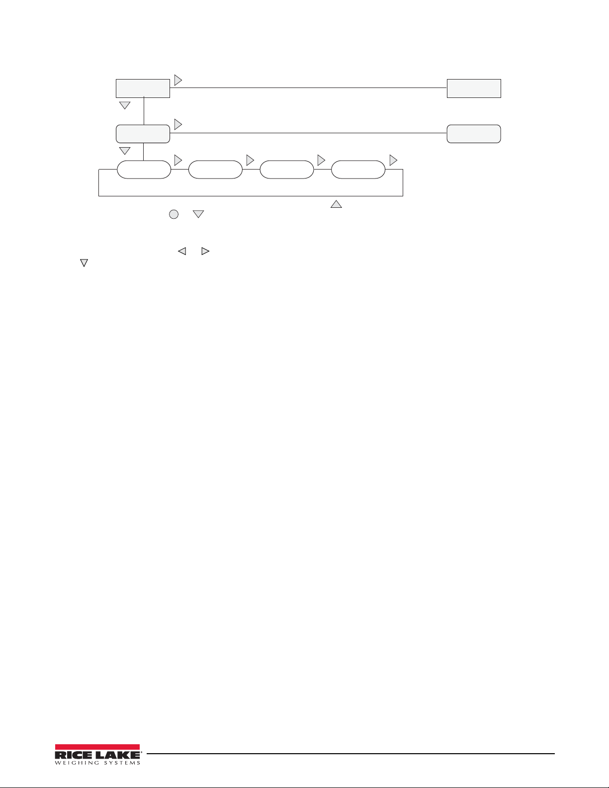
1st Level
Parameter
Default value Value
When moving through values below the first menu level, press to return to the
level above. Press or to move to the next parameter on the level above.
1st Level
Parameter
2nd Level
Parameter
2nd Level
Parameter
Value
Value
Figure 3-6. Setup Mode Menu Navigation
To select a parameter, press or to scroll left or right until the desired menu group appears on the display, then
press
to move down to the submenu or parameter you want. When moving through the menu parameters, the
default or previously selected value appears first on the display.
Configuration 21
Page 28
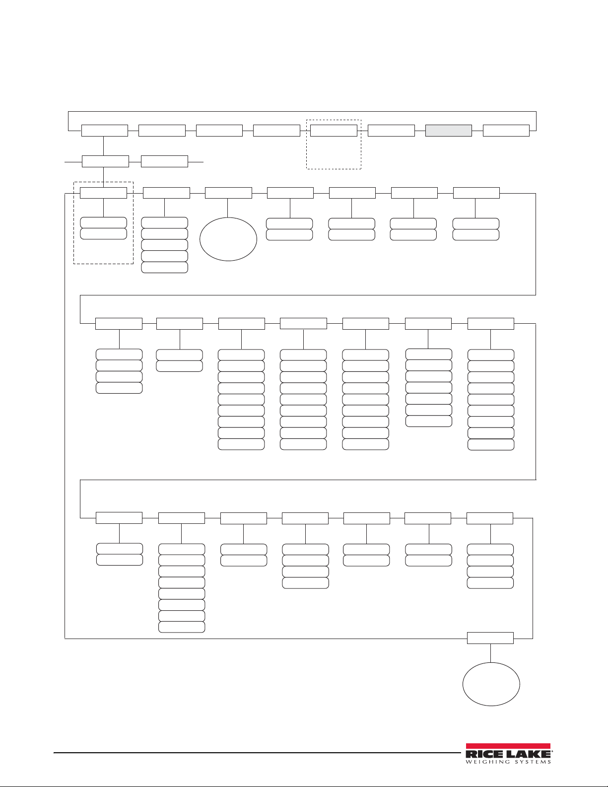
3.2.1 SCALES Menu
SCALES SERIAL FEATURE PFORMT DIG I/O ALGOUT VERS
SCALE 1
GRADS ZRANGE MOTBAND
OVRLOAD
SSTIME
DIGFLT1
DIGFLT2
10000
number
ZTRKBND
0
number
1.900000
number
1
number
FS+2%
FS+9D
FS+1D
FS
number
10
64
128
4
16
8
32
256
DFSENS
RATTRAP
DFTHRH
PWRUPMD TAREFN
32OUT
64OUT
2OUT
8OUT
4OUT
16OUT
128OUT
20D
50D
250D
5D
2D
10D
100D
NONE
200D
OFF
ON
SMPRAT
960HZ
7.5HZ
30HZ
240HZ
120HZ
480HZ
15HZ
60HZ
GO
DELAY
BOTH
PBTARE
NOTARE
KEYED
See
FORMAT
Submenu
1
2
DIGFLT3
ACCUM
CALIBR
OFF
ON
VISIBL
ON
OFF
FORMAT
See
CALIBR
Submenu
64
128
4
16
8
32
256
1
2
64
128
4
16
8
32
256
1
2
WMTTHRH
number
1000
SPLIT
PEAK HOLD
OFF
BI-DIR
NORMAL
AUTO
3INTVL
3RNG
2RNG
2INTVL
OFF
Specify for
SPLIT = OFF
CONFIG
SETPTS
720i Batching
V
ersion only
see page 57
The SCALES menu is shown in Figure 3-7. The FORMAT submenu is shown in Figure 3-8 on page 26; the
CALIBR submenu is shown in Figure 3-10 on page 32. Parameters shown in each diagram are described in the
table following that diagram.
22 720i Installation Manual
Figure 3-7. SCALES Menu
Page 29

SCALES Menu
Note
Parameter Choices Description
Level 2 submenus
SCALE 1 Allows configuration and calibration of each scale
CONFIG Scale hardware configuration (A/D or serial scale)
Level 3 submenus
GRADS 10000
1–9999999
SPLIT OFF
2RNG
3RNG
2INTVL
3INTVL
FORMAT PRIMAR
SECNDR
TERTIA
ROC
ZTRKBND 0
number
Specifies the number of full scale graduations if SPLIT=OFF
multi-interval scales (SPLIT
display divisions specified for the range or interval.)
The value entered must be in t
requirements and environmental limits on system resolution.
To calculate GRADS, use the formula: GRADS = Capaci
Display divisions are specified under
Specifies whether the scale is full-range (OFF), m
(2INTVL, 3INTVL). For multi-range and multi-interval scales, see the submenu shown in
Figure 3-9 on page 30 and parameter descriptions in Ta bl e 3-4 on page 31.
For standard scales (SPLIT=OFF), see Level 4 submenu descriptions in Tab le 3-3 on
page 27.
For multi-range and multi-interval scales, see Tab l e 3-4 on page 31.
Automatically zeroes the scale when
within the ZRANGE and scale is at standstill. Specify the zero tracking band in ± display
divisions. Maximum legal value varies depending on local regulations.
For scales using linear calibration, do not set the zero tracking band
to a value greater than that specified for the first linearization point.
OFF), the GRADS value is derived from the capacity and
he range 1–9999999 and should be consistent with legal
the FORMAT submenu.
within the range specified, as long as the input is
. (For multi-range and
ty / Display Divisions.
ulti-range (2RNG, 3RNG), or multi-interval
ZRANGE 1.900000
number
MOTBAND 1
number
SSTIME 10
number
OVRLOAD FS+2%
FS+1D
FS+9D
FS
WMTTHRH 1000
number
Selects the range within which the scale can be zer
1.9% around the calibrated zero point, for a total range of 3.8%. Indicator must be at
standstill to zero the scale. Use the default value for legal-for-trade applications.
Sets the level, in display divisions, at which
detected for 1 second or more, the standstill symbol lights. Some operations, including
print, tare, and zero, require the scale to be at standstill. Maximum legal value varies
depending on local regulations.
If this parameter is set to 0, the standstill an
operations including zero, print, and tare will be performed regardless of scale motion. If 0 is
selected, ZTRKBND must also be set to 0.
Specifies the length of time the scale must be ou
the scale is considered to be at standstill. Values greater than 10 are not recommended.
Determines the point at which the
displayed. Maximum legal value varies depending on local regulations.
Specifies the minimum number of grads requir
recorded number of weighments.
display blanks and an out-of-range error message is
oed. The 1.900000 default value is ±
scale motion is detected. If motion is not
nunciator will be set continuously on, and
t of motion, in 0.1-second intervals, before
ed for a weighment to be added to the
Table 3-2. SCALES Menu Parameters
Configuration 23
Page 30

Note
SCALES Menu
Parameter Choices Description
DIGFLT1
DIGFLT2
DIGFLT3
DFSENS 2OUT
DFTHRH NONE
RATTRAP OFF
SMPRAT 30HZ
PWRUPMD GO
4
8
16
32
64
128
256
1
2
4OUT
8OUT
16OUT
32OUT
64OUT
128OUT
2D
5D
10D
20D
50D
100D
200D
250D
ON
120HZ
240HZ
480HZ
960HZ
7.5HZ
15HZ
60HZ
DELAY
Selects the digital filtering
immediate area of the scale.
Choices indicate the number of A/
displayed reading. A higher number gives a more accurate display by minimizing the effect
of a few noisy readings, but slows down the settling rate of the indicator.
When configuring non-A/D scales, set the DIGFLTx parameters to
1 to disable filtering.
See Section 11.7 on page 107 for more infor
Digital filter cutout sensitivity. Specifies the number of c
outside the filter threshold (DFTHRH parameter) before digital filtering is suspended.
See Section 11.7 on page 107 for more information about digital filtering.
Digital filter cutout threshold. Specifies the filter thr
specified number of consecutive scale readings (DFSENS parameter) fall outside of this
threshold, digital filtering is suspended. If NONE is selected, the filter is always enabled.
See Section 11.7 on page 107 for more information about digital filtering.
Enables RATTLETRAP
vibrations caused by mechanical noise from nearby machines but may increase settling
times over standard digital filter selections.
Sample rate. Selects measurement rate, in samples per second, of the analog-to-digital
converter
Hz value may be too fast to provide the desired stability in some static weighing
applications.
Power up mode. In GO mode, the indicator goes in
power up display test.
. Lower sample rate values provide greater signal noise immunity: the default 120
rate used to reduce the effects of mechanical vibration from the
D conversions per update that are averaged to obtain the
®
digital filtering. RATTLETRAP is most effective at filtering repeating
mation about digital filtering.
onsecutive readings that must fall
eshold, in display divisions. When a
to operation immediately after a brief
TAREFN BOTH
NOTARE
PBTARE
KEYED
ACCUM OFF
ON
VISIBL ON
OFF
24 720i Installation Manual
In DELAY mode, the indicator performs a power up displa
warm up period. If no motion is detected during the warm up period, the indicator becomes
operational when the warm up period ends; if motion is detected, the delay timer is reset
and the warm up period repeated.
Enables or disables push-button and keyed
BOTH: Both push-button and ke
NOTARE: No tare allowed (gross mode only)
PBTARE: Push-button tares enabled
KEYED: Keyed tare enabled
Accumulator. Specifies whether the scale accumulator is enabled. If enabled, accumulation
occurs whenever a print operation is performed.
Scale visibility. Specifies whether scale data is displayed.
tares. Possible values are:
yed tares are enabled
y test, then enters a 30-second
Table 3-2. SCALES Menu Parameters (Continued)
Page 31

SCALES Menu
Parameter Choices Description
PEAK HOLD OFF
NORMAL
BI-DIR
AUTO
CALIBR WZERO
WVAL
WSPAN
WLIN
REZERO
Peak hold. Used to determine, display, and print the greatest net weight read during a
weighing cycle. The weighing cycle ends when a print command is executed (AUTO setting)
or when the peak weight is cleared by pressing ZERO or PRINT. Press GROSS/NET to
display gross weight data when using the peak hold function.
OFF Peak hold function is off.
NORMAL Positive peak, manual reset. Greatest net weight is held in memory until the
weight is removed from the scale and either the ZERO or PRINT key is pressed.
BI-DIR Bi-directional peak, manual reset. Same as NORMAL, but peak value can be
either positive or negative, determined by absolute value.
AUTO Positive peak, auto print, auto reset. Automatic print occurs when scale load is 0
± 10 display divisions and at standstill. Following the print command, the peak
value is cleared and reset automatically.
See Level 4 submenu descriptions in Table 3-5 on page 32 and Section 4.2 on page 47.
Table 3-2. SCALES Menu Parameters (Continued)
Configuration 25
Page 32

FORMAT
PRIMAR
DECPNT
88.88888
888.8888
8888888
8888800
8888880
8.888888
8888.888
88888.88
888888.8
DSPDIV
1D
5D
2D
UNITS
TN
T
LB
G
KG
OZ
GR
troyoz
troylb
LT
CUSTOM
NONE
SECNDR
DECPNT
88.88888
888.8888
8888888
8888800
8888880
8.888888
8888.888
88888.88
888888.8
DSPDIV
5D
2D
1D
UNITS
TN
T
lb
G
KG
OZ
GR
troyoz
troylb
LT
CUSTOM
NONE
MULT
0.453592
number
TERTIA
DECPNT
88.88888
888.8888
8888888
8888800
8888880
8.888888
8888.888
88888.88
888888.8
DSPDIV
5D
2D
1D
UNITS
TN
T
G
KG
OZ
GR
troyoz
troylb
LT
CUSTOM
MULT
0.453592
number
ROC
DECPNT
88.88888
888.8888
8888888
8888800
8888880
8.888888
8888.888
88888.88
888888.8
DSPDIV
2D
1D
5D
MULT
1.000000
number
UNITS
MIN
SEC
HOUR
INTERVL
number
10
REFRESH
number
0.100000
GRADS ZRANGE MOTBANDZTRKBND
…
…
OFF
OFF
lb
NONE
OFF
SPLIT
26 720i Installation Manual
Figure 3-8. SCALES Menu, FORMAT Submenu, SPLIT = OFF
Page 33

SCALES Menu, FORMAT Submenu, SPLIT = OFF
Parameter Choices Description
Level 4, FORMAT submenu
PRIMAR DECPNT
DSPDIV
UNITS
SECNDR DECPNT
DSPDIV
UNITS
MULT
TERTIA DECPNT
DSPDIV
UNITS
MULT
ROC DECPNT
DSPDIV
MULT
TIME
INTERVL
REFRESH
Level 5 submenus
Primary Units (PRIMAR) Parameters
DECPNT 8888888
8888880
8888800
8.888888
88.88888
888.8888
8888.888
88888.88
888888.8
DSPDIV 1D
2D
5D
UNITS LB
KG
G
OZ
TN
T
GR
troyoz
troylb
LT
CUSTOM
NONE
OFF
Specifies the decimal position, display divisions, and units used for the primary units. See
Level 5 submenu parameter descriptions.
Specifies the decimal position, display divisions, units, and conversion multiplier used for the
secondary units. See Level 5 submenu parameter descriptions.
Specifies the decimal position, display divisions, units, and conversion multiplier used for the
tertiary units. See Level 5 submenu parameter descriptions.
Specifies the decimal position, display divisions, conversion multiplier, time units, update
interval, and refresh interval used for the rate of change units. See Level 5 submenu
parameter descriptions.
Decimal point location. Specifies the location of the decimal point or dummy zeroes in the
primary unit display. Value should be consistent with local legal requirements.
Display divisions. Selects the minimum division size for the primary units displayed weight.
Specifies primary units for displayed and printed weight. Values are: LB=pound;
KG=kilogram; G=gram; OZ=ounce; TN=short ton; T=metric ton; GR=grain; troyoz=troy
ounce; troylb=troy pound; LT=long ton.
Table 3-3. SCALES Menu, FORMAT Submenu Parameters, SPLIT = OFF
Configuration 27
Page 34

SCALES Menu, FORMAT Submenu, SPLIT = OFF
Parameter Choices Description
Secondary Units (SECNDR) and Tertiary Units (TERTIA) Parameters
DECPNT 888888.8
8888888
8888880
8888800
8.888888
88.88888
888.8888
8888.888
88888.88
DSPDIV 2D
5D
1D
UNITS LB
KG
G
OZ
TN
T
GR
troyoz
troylb
LT
CUSTOM
NONE
OFF
MULT 0.453592
0.000001–
9999999
Decimal point location. Determines the location of the decimal point or dummy zeros in the
secondary or tertiary units display.
Display divisions. Selects the value of minimum division size of the displayed weight for
secondary or tertiary units display.
Specifies secondary or tertiary units for displayed and printed weight. Values are:
LB=pound; KG=kilogram; G=gram; OZ=ounce; TN=short ton; T=metric ton; GR=grain;
troyoz=troy ounce; troylb=troy pound; LT=long ton.
Multiplier. Specifies the conversion factor by which the primary units are multiplied by to
obtain the secondary or tertiary units. The default is 0.453592, which is the conversion
factor for changing pounds to kilograms. See
multipliers.
Section 11.8 on page 108 for a list of
To shift between primary, secondary, and tertiary units, press the UNITS key.
Rate of Change (ROC) Units Parameters
For applications using the ROC function, the primary scale should be configured with a finer resolution than the rate of change
(ROC) units to prevent a stepwise appearance in the ROC display. The ROC display step size (weight increment between
displayed values) can be roughly calculated as follows:
(updates_per_ROC_UNIT) * (PRIMARY_resolution / ROC_resolution)
For example, with INTERVL=30; REFRESH =0.1; UNITS=MIN; PRIMARY resolution at 0.1 LB and ROC resolution at 1.0 (LB/
MIN):
- INTERVL * REFRESH = 30 * 0.1 = 3.0 seconds per update (ROC data is flushed every 3.0 seconds)
- With UNITS = MIN, there are 20 ROC data updates per ROC time unit: 60 seconds / 3.0 seconds per update
- The resolution ratio of PRIMARY to ROC units is 0.1 (0.1 / 1.0)
- This configuration provides a step size in the ROC display of 2 LB (2 LB increments between displayed values):
20 * 0.1 = 2
Note that setting both PRIMARY and ROC display resolutions to 1 LB would have resulted in a step size of 20 LB.
Table 3-3. SCALES Menu, FORMAT Submenu Parameters, SPLIT = OFF (Continued)
28 720i Installation Manual
Page 35

SCALES Menu, FORMAT Submenu, SPLIT = OFF
Parameter Choices Description
DECPNT 8888888
8888880
8888800
8.888888
88.88888
888.8888
8888.888
88888.88
888888.8
DSPDIV 1D
2D
5D
MULT 1.0
0.000001–
9999999
UNITS SEC
MIN
HOUR
INTERVL 10
1–100
REFRESH 0.1
0.1–60
Decimal point location. Determines the location of the decimal point or dummy zeros in the
display.
Display divisions. Selects the minimum division size for the ROC units displayed weight.
Multiplier. Specifies the conversion factor by which the primary units are multiplied by to
obtain the displayed rate of change units.
See Section 11.8 on page 108 for information about conversion factors.
Rate-of-change units.
Update interval. Specifies the number of refreshes over which the rate-of-change is
calculated.
For example, with REFRESH set to 0.1 second and INTERVL at 60, each weight value takes
6 seconds (0.1 * 60) to be flushed from the ROC data.
Refresh interval. Specifies the number of seconds between rate-of-change samples.
Table 3-3. SCALES Menu, FORMAT Submenu Parameters, SPLIT = OFF (Continued)
Configuration 29
Page 36

FORMAT ZRANGE MOTBANDZTRKBND
…
…
SPLIT
DECPT1
88.88888
888.8888
8888888
8888800
8888880
8.888888
8888.888
88888.88
888888.8
DDIV1
1D
5D
2D
UNITS
TN
T
LB
G
KG
OZ
GR
troyoz
troylb
LT
CUSTOM
NONE
OFF
MAX1
2000
weight
DECPT2
88.88888
888.8888
8888888
8888800
8888880
8.888888
8888.888
88888.88
888888.8
DDIV2
5D
2D
1D
MAX2
5000
weight
DECPT3
88.88888
888.8888
8888888
8888800
8888880
8.888888
8888.888
88888.88
888888.8
DDIV3
5D
2D
1D
MAX3
10000
weight
If SPLIT = 3RNG or 3INTVL
Figure 3-9. FORMAT Submenu, SPLIT OFF (Multi-range and Multi-interval Scales)
30 720i Installation Manual
Page 37

SCALES Menu, FORMAT Submenu, SPLIT OFF
Parameter Choices Description
Level 4, FORMAT submenu
DECPT1 8888888
8888880
8888800
8.888888
88.88888
888.8888
8888.888
88888.88
888888.8
DDIV1 1D
2D
5D
MAX1 2000
weight
DECPT2 888888.8
8888888
8888880
8888800
8.888888
88.88888
888.8888
8888.888
88888.88
DDIV2 2D
5D
1D
MAX2 5000
weight
DECPT3 888888.8
8888888
8888880
8888800
8.888888
88.88888
888.8888
8888.888
88888.88
DDIV3 2D
5D
1D
MAX3 10000
weight
Decimal point location for first range or interval. Specifies the location of the decimal point or
dummy zeroes in the primary unit display. Value should be consistent with local legal
requirements.
Display divisions for first range or interval. Selects the minimum division size for the primary
units displayed weight.
Maximum weight for first range or interval.
Decimal point location for second range or interval. Specifies the location of the decimal
point or dummy zeroes in the primary unit display. Value should be consistent with local legal
requirements.
Display divisions for second range or interval. Selects the minimum division size for the
primary units displayed weight.
Maximum weight for second range or interval.
Decimal point location for third range or interval (SPLIT = 3RNG or 3INTVL only). Specifies
the location of the decimal point or dummy zeroes in the primary unit display. Value should
be consistent with local legal requirements.
Display divisions for third range or interval (SPLIT = 3RNG or 3INTVL only). Selects the
minimum division size for the primary units displayed weight.
Maximum weight for third range or interval (SPLIT = 3RNG or 3INTVL only).
Table 3-4. SCALES Menu, FORMAT Submenu Parameters, SPLIT OFF
Configuration 31
Page 38

Note
Note
WZERO WVAL WSPAN WLIN REZERO
POINT 4 POINT 5 POINT 1 POINT 2POINT 3
VISIBLE GRADS FORMATCALIBR
…
…
SCALES Menu, FORMAT Submenu, SPLIT OFF
Parameter Choices Description
UNITS LB
KG
G
OZ
TN
T
GR
troyoz
troylb
LT
CUSTOM
NONE
OFF
Specifies primary units for displayed and pr
KG=kilogram; G=gram; OZ=ounce; TN=short ton; T=metric ton; GR=grain; troyoz=troy
ounce; troylb=troy pound; LT=long ton.
Table 3-4. SCALES Menu, FORMAT Submenu Parameters, SPLIT OFF (Continued)
inted weight. Values are: LB=pound;
Figure 3-10. SCALES Menu, CALIBR Submenu
SCALES Menu, CALIBR Submenu
Parameter Choices Description
Level 4, CALIBR submenu
WZERO — Press ENTER to display and edit the zero cal
WVAL — Press ENTER to display and edit
If unable to change value using keypad, use the following method to enter new
value:
To enter new value use the up/down keys to chan ge th e fi rst di git to desired
er. Then use the key pad to enter the rest of the numbers.
numb
the test weight value.
ibration A/D count or millivolts value.
Example: To enter 25000 change the first number using up/down arrows to 2. Then use the keypad and
enter 5000. The result will be 25000.
WSPAN — Press ENTER to display and edit the span calibration A/D count or millivolts value.
WLIN POINT 1 —
T 5
POIN
REZERO — Press ENTER to remove an offset value fr
Press ENTER to display and edit test weight and calibration values for up to five linearization points.
Perform linear calibration only after WZERO and WSPAN have been set.
om the zero and span calibrations.
Use this parameter only after WZERO and WSPAN have been set. See
Section 4.2 on page 47 for more information about using this parameter.
Table 3-5. SCALES Menu, CALIBR Submenu Parameters
32 720i Installation Manual
Page 39

3.2.2 SERIAL Menu
BAUD TERMINBITS
600
1200
38400
57600
300
2400
28800
9600
4800
19200
8NONE
7ODD
7EVEN
CR/LF
CR
EOLDLY
0
number
HANDSHK
OFF
HRDWAR
STREAM
OFF
INDUST
LFT
SOURCE
List of
configured
scales
If STREAM ≠ OFF
SFMT
format
XONXOFF
8ODD
8EVEN
STOP BITS
2
1
ECHO
ON
OFF
RESPONSE
ON
OFF
PORT 2
…
CMD
115200
4KEYS
DISPLAY
KEYPAD
720i Batching Version only
SCALES SERIAL FEATURE PFORMT DIG I/O ALGOUT VERS
SETPTS
720i Batching
V
ersion only
see page 57
See Section 11.6 on page 106 for information about 720i serial data formats.
Figure 3-11. SERIAL Menu, Port 2
Configuration 33
Page 40

BAUD TERMINBITS
600
1200
38400
115200
57600
300
2400
28800
9600
4800
19200
8NONE
7ODD
7EVEN
CR/LF
CR
SFMT
format
If PORT = CMD
CMD
8ODD
8EVEN
STOP BITS
2
1
SCALE
See CMD Selections
…
IND SC
ADDRESS
0
number
PORTTYPE
232
485
DUPLEX
HALF
FULL
If PORTTYPE = 485
HANDSHK
OFF
XONXOFF
EOLDLY
0
number
ECHO
ON
OFF
RESPONSE
ON
OFF
STREAM
OFF
INDUST
LFT
If PORT = CMD
4KEYS
DISPLAY
KEYPAD
RS-485 can be specified
for PORT 7
(serial expansion card) only
PORT 4
Optional Ports 7 or 8
Only when in Command Mode
TOKENS
PRIMAR
TARE
Selectable token characters
If STREAM = LFT or INDUST
720i Batching Version only
720i Batching Version only
SCALES SERIAL FEATURE PFORMT DIG I/O ALGOUT VERS
SETPTS
720i Batching
V
ersion only
see page 57
Figure 3-12. SERIAL Menu, Port 4 and Expansion Ports
34 720i Installation Manual
Page 41

SERIAL Menu
Note
Note
Note
Parameter Choices Description
Level 2 submenus
PORT 2
PORT 4
Level 3 Submenus Ports 2 and 4
BAUD 9600
BITS 8NONE
STOP BITS 2
ECHO ON
RESPONSE ON
TERMIN CR/LF
EOLDLY 0
HANDSHK OFF
PORTTYPE 232
CMD
SCALE
IND SC
19200
28800
38400
57600
115200
300
600
1200
2400
4800
7EVEN
7ODD
8ODD
8EVEN
1
OFF
OFF
CR
0–255
XONOFF
HRDWAR
485
Specifies the type of data received by the port:
SCALE: Legal-for-trade serial scale input
IND SC: Industrial (non-legal-for
KEYBD is available only on Port 1; SCALE, IND SC are available only on Port 4 and higher
(expansion ports).
The keyboard interface is not hot-pluggable. Power-off the 720i
before attaching keyboard cable to the Port 1 connector.
with the detached display module (DDM); changing these parameters will disable the
display.
Print format outputs default to Port 4; if using Port 4 for other scale connections,
reas
sign needed print formats to another port before configuring.
Baud rate. Selects the transmission speed for the port.
Selects number of data bits and parity of data transmitted or received by the port.
Selects number of stop bits transm
Specifies whether characters received by the port ar
Specifies whether the port transmits
Termination character. Selects termination
End-of-line delay. Sets the delay period, in 0.1-se
terminated to the beginning of the next formatted serial output. Value specified must be in the
range 0-255, in tenths of a second (10 = .1 second).
Specifies whether XON/XOFF flow control charact
Hardware handshaking is available only on Port 2.
Specifies whether the port is used for RS-232 or RS-485 communications. If 485 is selected
(Port
7 only), additional prompts are shown to specify half- or full-duplex operation and
RS-485 address.
DO NOT EDIT PORT 3 PARAMETERS. Port 3 provides communications
The maximum baud rate for ports on serial expansion cards
(port number greater than 4) is 19200.
RS-485 communications can be specified for Port 7 (serial expansion card)
only.
-trade) scale input
itted or received by the port.
replies to serial commands.
character for data sent from the port.
e echoed back to the sending unit.
cond intervals, from when a formatted line is
ers or hardware handshaking is used.
Table 3-6. Serial Menu Parameters
Configuration 35
Page 42

Note
SERIAL Menu
Parameter Choices Description
DUPLEX HALF
FULL
ADDRESS 0
0–255
TOKENS PRIMAR
SECNDR
TERTIA
GROSS
INVALID
MOTION
ZERO
NET
OK
RANGE
TAR E
STREAM OFF
LFT
INDUST
4KEYS
KEYPAD
SFMT format Specifies the stream format used for the streamed data (CMD
Specifies whether the RS-485 communications is half- or full-duplex.
Specifies the decimal indicator address for RSdisabled if an address other than zero is specified for this parameter. RS-485 addresses must
be in the range 01–255.
If STREAM is set to LFT or INDUST, the TOKENS parameter can be used to replace tokens
used in the da
information about custom stream formatting.
Specifies what data, if any, is streamed from the port.
LFT updates streamed data at the display
streamed.
INDUST streams data at the A/D update rate specified by
SCALES menu (page 22).
4KEYS and KEYPAD stream keypad events to a r
keypad events; 4KEYS transmits key presses of the ZERO, GROSS/NET, TAR E, and UNITS
keys only.
is the Rice Lake format (see Section 11.6 on page 106). See Section 11.5 on page 103 for
information about custom stream formatting.
ta stream from the indicator front panel. See Section 11.5 on page 103 for more
Streaming is not supported for RS-485 connections.
The print key always prints locally.
485 connections. RS-232 communications is
rate, so only weight values shown on the display are
eceiving indicator. KEYPAD transmits all
the SMPRATE parameter on the
scale type). The default format
Table 3-6. Serial Menu Parameters (Continued)
36 720i Installation Manual
Page 43

3.2.3 FEATURE Menu
DATE
DATEFMT DATESEP
DDMMYYYY
YYYYMMDD
MMDDYYYY
YYYYDDMM
DASH
SEMI
SLASH
TIME
TIMEFMT TIMESEP
24HOUR
12HOUR
COMMA
COLON
DECFMT
COMMA
DOT
CONSNUM
number
0
CONSTUP
number
0
TRUCK
OFF
CFGPWD
number
0
LOCALE
ON
OFF
LATUDE
number
45
ELEVAT
number
345
If LOCALE = ON
REGWORD
BRUTTO
GROSS
REGULAT
CANADA
NTEP
OIML
NONE
INDUST
See
INDUST
Submenu
KYBDLK
ON
OFF
ZERONLY
ON
OFF
ALIBI
ON
OFF
HEARTBEAT
0.5
1.0
1.5
2.0
2.5
3.0
OFF
3.5
4.0
SOFTKEYS
List of
available and
configured
softkeys
ADVANCE MODE
MATERIAL
CUSTOMER
VEHICLE
SOURCE
DELIVERY
DELIVERY WGT
REMARKS
ADVANCE
MODE1
MODE2
MODE3
MODE4
MODE5
MODE6
REPRINT
SHIFTS
PRINT
DAY
SERIAL
NUMBER
SHIFT 1 - 3
DAY START
DAY END
HHMMSS
HHMMSS
SHIFT # START
SHIFT # END
SCALES SERIAL FEATURE PFORMT DIG I/O ALGOUT VERS
SETPTS
720i Batching
V
ersion only
see page 57
The FEATURE menu is used to set miscellaneous system attributes, including time and date, truck mode, softkey
definitions, and parameters relating to the regulatory environment. See Table 3-7 on page 38 for parameter
descriptions.
Figure 3-13. FEATURE Menu
Configuration 37
Page 44

FEATURE Menu
Note
Parameter Choices Description
Level 2 submenus
DATE DATEFMT
DATESEP
TIME TIMEFMT
TIMESEP
DECFMT DOT
COMMA
CONSNUM 0
0–9999999
CONSTUP 0
0–9999999
TRUCK OFF
MODE1
MODE2
MODE3
MODE4
MODE5
MODE6
ADVANCE
Allows selection of date format and date sepa
parameter descriptions.
Use the TIME/DATE softkey or the SD serial command to set the date. See Section 10.0
on page 86 for information about using the serial commands.
Allows selection of time format and separator character. See Level 3 submenu parameter
iptions.
descr
Use the TIME/DATE softkey or the ST ser
on page 86 for information about using the serial commands.
Specifies whether decimal numbers are displayed using a period (DOT) or comma as the
al symbol.
decim
Consecutive numbering. Allows sequential number
consecutive number value is incremented following each print operation that includes
<CN> in the ticket format. When the consecutive number is reset, it is reset to the value
specified on the CONSTUP parameter.
Specifies the consecutive number start-up value used when the
reset by sending the KCLRCN serial command or a CLRCN digital input. Value specified
must be in the range 0–9 999 999.
Specifies the truck mode used. If selected, the i
the selected truck mode. See Section 7.0 on page 58 for more information about using
the truck modes.
MODE1: Auto clear ID, keyed tar
MODE2: Auto clear ID, no keyed tares, value swapping
MODE3: Stored ID, keyed tares, value swapping
MODE4: Stored ID, no keyed tares, value swapping
MODE5: Stored ID, keyed tar
MODE6: Stored ID, no keyed tares, no value swapping
ADVANCE: Enables the advance mode.
Modes 1 - 6 have stored tare weight by Truck ID, Advance mode does
not have stored tare weight, only stored transactions.
es, value swapping
es, no value swapping
ial command to set the time. See Section 10.1
rator character. See Level 3 submenu
ing for print operations. The
consecutive number is
ndicator switches from normal mode to
ADVANCE
MODE
ALIBI OFF
38 720i Installation Manual
VEHICLE
MATERIAL
CUSTOMER
SOURCE
DELIVERY
DELIVERY WGT
REMARKS
PRINT
REPRINT
SHIFTS
DAY
SERIAL NUMBER
ON
ON or OFF, default is ON
ON or OFF, default is ON
ON or OFF, default is ON
ON or OFF, default is ON
ON or OFF, default is ON
ON or OFF, default is ON
ON or OFF, default is ON
ON, OFF or PROMPT, default is ON
ON or OFF
SHIFT 1, SHIFT 2, SHIFT 3
DAY START, DAY END
Enter Serial Number (Ticket Serial Number) 0-99999999 (Default is 0)
See Tabl e 7-2 on page 59 for more information
Specifies whether data storage is used by the a
transaction.
Use the SOFTKEYS parameter to enable a softkey for r
See Section 11.12 on page 110 for more information about
on each prompt.
libi feature to allow reprinting any
ecalling alibi print transactions.
using the alibi feature.
Table 3-7. FEATURE Menu Parameters
Page 45

Note
FEATURE Menu
Parameter Choices Description
CFGPWD 0
0–9999999
reset=999999
KYBDLK OFF
ON
ZERONLY OFF
ON
SOFTKEYS None
<blank>
Time/Date
Display Tare
Display Accum
Display ROC
Alibi
Setpoint
Batch Start
Batch Stop
Batch Pause
Batch Reset
Weigh
Reports
Management
Weigh In
Weigh Out
Truck R e g s
SKUD 1-10
REGULAT NTEP
CANADA
INDUST
NONE
OIML
REGWORD GROSS
BRUTTO
Configuration password. Specify a non-zero value to restrict access to all configuration
menus and PCE.
If a configuration password is specified, be sure to record the password
and keep it in a safe place. If the configuration password is lost or
unavailable, the indicator must be cleared (reset configuration and
calibration parameters) to continue use.
To clear the indicator, press the setup switch, then enter 999999 (six nines) at the
configuration password prompt. The unit performs a RESETCONFIGURATION then
returns to the setup mode configuration display.
Keyboard lock. Specify ON to disable the keypad in normal mode.
Zero key only. Specify ON to disable all fr
Softkeys provide additional operator functions for specif
listed on the tabs shown at the bottom of the LCD display; functions are activated by
pressing the arrow keys below the softkey tabs.
These features are only available with the 720i Batching version software.
These features are available with the Advanced T
These features are available with the T
User-programmable softkeys; defined by PCEE.
Regulatory mode. Specifies the r
• OIML, NTEP, and CANADA modes allow a tare to be ac
than zero. NONE allows tares to be acquired at any weight value.
• OIML, NTEP, and CANADA modes allow a tare
is at no load. NONE allows tares to be cleared at any weight value.
• NTEP and OIML modes allow a ne
present. In CANADA mode, the previous tare must be cleared before a new tare can
be acquired.
• NONE, NTEP and CANADA modes allow the scale to be zer
mode as long as the current weight is within the specified ZRANGE. In OIML mode,
the scale must be in gross mode before it can be zeroed; pressing the ZERO key in
net mode clears the tare.
• INDUST provides a set of subparameters to al
print functions in non-legal-for-trade scale installations. See Level 4 parameter
descriptions in Table 3-8 on page 41.
The value specified for this parameter affects the function of
ZERO keys. See Section 11.2 on page 101 for a complete description of TARE and ZERO
key functions for each of the regulatory modes.
Sets the term displayed when weighing in gross mode. Selecting BRUTTO replaces the
Gross annunciator with Brutto.
egulatory agency having jurisdiction over the scale site.
ont panel keys except ZERO in normal mode.
ruck Modes 1-6 Only.
w tare to be acquired even if a tare is already
ic applications. Assignments are
ruck Mode Only.
quired at any weight greater
to be cleared only if the gross weight
oed in either gross or net
low customization of tare, clear, and
the front panel TARE and
Table 3-7. FEATURE Menu Parameters (Continued)
Configuration 39
Page 46

FEATURE Menu
Parameter Choices Description
HEARTBEAT OFF, 0.5—4.0 Specifies, in seconds, the rate of the heartbeat signal sent from the host to the display
module. The heartbeat is used to verify active communications between the host and the
display and to ensure that the displayed data is current.
If specified, the display module input heartbeat (HB1:I parameter) must also be set,
typically to a value slightly longer than the host HEARTBEAT parameter. (For example,
Section 11.11 on page 110 for more information about
LOCALE OFF
ON
LATUDE 45
0–90
ELEVAT 345
±0–9999
Level 3 submenus
DATEFMT MMDDYYYY
DDMMYYYY
YYYYMMDD
YYYYDDMM
DATESEP SLASH
DASH
SEMI
TIMEFMT 12HOUR
24HOUR
TIMESEP COLON
COMMA
SHIFT 1 - 3 SHIFT # START
SHIFT # END
DAY START
DAY END
HHMMSS
HHMMSS
HEARTBEAT=1.5, HB1:I=2.0.) See
configuring the display module.
Locale. Set this parameter ON to enable the LATUDE and ELEVAT parameters. Specifying
latitude and elevation of the scale site provides compensation for gravitational effects.
Attached scales must be recalibrated after changing this parameter from OFF to ON.
Latitude. Specify the latitude of the scale site in degrees. This parameter is shown only if
LOCALE=ON.
Elevation. Specify the elevation of the scale site in meters. Valid values are –9999 through
9999. This parameter is shown only if LOCALE=ON.
Specifies the format used to display or print the date.
Specifies the date separator character.
Specifies the format used to display or print the time.
Specifies the time separator character.
Specifies the shift start and end time in 24 hour format (HHMMSS)
Specifies the day start and end time in 24 hour format (HHMMSS)
40 720i Installation Manual
Table 3-7. FEATURE Menu Parameters (Continued)
Page 47

FEATURE Menu, REGULAT/INDUST Submenu
REGULAT
SNPSHOT
DISPLAY
INDUST
SCALE
HTARE
NO
YES
ZTARE
NO
YES
KTARE
YES
NO
MTARE
REPLACE
REMOVE
NOTHING
NTARE
NO
YES
CTARE
YES
NO
PRTMOT
NO
YES
PRTPT
NO
YES
PRTHLD
NO
YES
HLDWGH
NO
YES
MOTWGH
NO
YES
AUDAGNCY
NTEP
CANADA
INDUST
NONE
OIML
OVRBASE
CALIB
SCALE
SCALES SERIAL FEATURE PFORMT DIG I/O ALGOUT VERS
SETPTS
720i Batching
V
ersion only
see page 57
The INDUST setting of the REGULAT parameter allows customization of several tare, clear, and print functions
for use in non-legal-for-trade scale installations. See Section 11.2 on page 101 for more information about
regulatory mode functions.
Figure 3-14. REGULAT / INDUST Submenu
FEATURE Menu, REGULAT / INDUST Submenu
Parameter Choices Description
Level 4, REGULAT / INDUST submenu
SNPSHOT DISPLAY, SCALE Display or Scale weight source.
HTARE NO, YES Allow tare in display hold
ZTARE NO, YES Remove tare on ZERO
KTARE YES, NO Always allow keyed tare
MTARE REPLACE
REMOVE
NOTHING
NTARE NO, YES Allow negative or zero tare
CTARE YES, NO Allow CLEAR key to clear tare/accumulator
PRTMOT NO, YES Allow print while in motion
PRTPT NO, YES Add PT to keyed tare print
PRTHLD NO, YES Print during display hold
HLDWGH NO, YES Allow truck weighment dur
MOTWGH NO, YES Allow truck weighment in motion
OVRBASE CALIB, SCALE Zero base for overload calculation
AUDAGNCY NTEP
CANADA
INDUST
NONE
OIML
Table 3-8. REGULAT / INDUST Submenu Parameters
Multiple tare action
Audit trail display agency format.
ing display hold
Configuration 41
Page 48

3.2.4 PFORMT Menu
GFMT NFMT ACCFMT
HDRFMT1 HDRFMT2 AUXFMT
TRWOUT TRFMT ALERT
Same as AUXFMT1
AUX1FMT AUX20FMT
PORT 2
PORT 4
PORT
...
PORT 2
PORT 4
PORT
SPFMT
720i
Batching Version
Software Only
FMT
SCALES SERIAL FEATURE PFORMT DIG I/O ALGOUT VERS
SETPTS
720i Batching
Version only
see page 57
TRWIN
See GFMT Menu
The PFORMT menu can be used to set the port used by each print format. Print formats can be viewed or edited
Revolution III, serial commands or the front panel. See Section 6.0 on page 52 for detailed information about
using
print formatting.
Figure 3-15. PFORMT Menu
42 720i Installation Manual
Page 49

3.2.5 DIG I/O Menu
BIT 1
INPUT
OUTPUT
OFF
ZERO
NT/GRS
BIT 2
SLOT 0
BIT 3 BIT 8
UNITS
PRINT
TARE
ACCUM
TIMDATE
KEY1
KEY2
KEY3
KEY4
KEY5
KEY6
KEY7
KEY9
KEYDP
KEY8
KEY0
ENTER
Same as BIT 1
SLOT 2
…
NAVUP
NAVDN
NAVLFT
NAVRGT
BIT 1
BIT 24
Same as SLOT 0, BIT 1
……
If DIG I/O Expansion Board
Is Installed
KBDLOC
HOLD
BATRUN
BATSTRT
BATPAUS
BATRESET
CLRCN
NET
PRIM
GROSS
SEC
CLRTAR
CLRACC
TER
BATSTOP
*720i
Batching Version
Software Only
DSPTAR
CLEAR
ESC
SETPT*
SCALES SERIAL FEATURE PFORMT DIG I/O ALGOUT VERS
SETPTS
720i Batching
V
ersion only
see page 57
The DIG I/O menu shown in Figure 3-16 is used to assign functions to digital inputs and outputs. SLOT 0
represents the eight I/O bits available on the CPU board (connector J6). The additional slot, with 24 I/O bits, is
shown only if the digital I/O expansion card is installed.
Figure 3-16. DIG I/O Menu
Configuration 43
Page 50

DIG I/O Menu
Parameter Choices Description
Level 2 submenus
SLOTx BIT y Lists available digital I/O slots.
Level 3 submenus
BIT y OFF
INPUT
OUTPUT
ZERO
NT/GRS
TARE
UNITS
PRINT
ACCUM
SETPTS
TIMDATE
ESC
CLEAR
DSPTAR
KEY0—KEY9
KEYDP
ENTER
NAVUP
NAVDN
NAVLFT
NAVRGT
KBDLOC
HOLD
TRUN
*BA
TSTRT
*BA
*BATPAUS
*BATRESET
TSTOP
*BA
CLRCN
GROSS
NET
PRIM
SEC
TER
CLRTAR
CLRACC
* 720i Batching Software Version Only
Specifies the function of the digital I/O bit.
• OFF indicates that the bit is not configured.
• INPUT assigns the bit as a digital input.
• OUTPUT assigns the bit as a digital output.
• ZERO, NT/GRS (net/gross mode toggle), TARE
functions as the five major front panel keys.
• ACCUM adds the current scale weight to the ac
enabled.
• SETPTS and TIMDATE provide the same function as the Setpoint and Time/Date softkeys.
• TIMDATE provides the same function as the Time/Date softkey.
• ESC provides a function equivalent to the Cancel softkey.
• CLEAR simulates pressing
• DSPTAR displays the current tare; equivalent to pressing the Display Tare softkey.
• KEY0—KEY9 and KEYDP (decimal point) simulate pr
• ENTER simulates pressing the front panel ENTER key.
• NAVUP, NAVDN, NAVLFT, and NAVRGT simulat
• KBDLOC locks the keyboard (indicator front panel) when held low.
• HOLD holds the current display. Releasing this
• BATRUN allows a batch routine to be started and run. With BATRUN active (low), the
BATSTRT input starts the batch; if BATRUN is inactive (high), BATSTRT resets the batch.
• BATSTRT starts or resets a batch routine, depending on the state of the BATRUN input.
• BATPAUS pauses a batch routine when held low.
• BATRESET stops the batch sequence and resets to the first batch step.
• BATSTOP stops the batch routine.
• CLRCN resets the consecutive number to the val
(FEATURE menu).
• GROSS, NET, PRIM, SEC, and TER select gross or net weight display, and primary,
secondary, or tertiary units display modes.
• CLRTAR clears the current tare for the active scale.
• CLRACC clears the active accumulator.
the front panel CLR key.
, UNITS, and PRINT provide the same
cumulator, if the scale accumulator is
essing keys on the numeric keypad.
e pressing the navigation keys.
input clears the running average filter.
ue specified on the CONSTUP parameter
44 720i Installation Manual
Table 3-9. DIG I/O Menu Parameters
Page 51

3.2.6 ALGOUT Menu
number
10000
number
SOURCE1
OFFSET
20%
0%
ERRACT
SCALE 1 FULLSC
HOLD
ZEROSC
MIN
number
000000
MINNEG
number
OFF
MAX
OFF
MAXNEG
MODE
GROSS
NET
If SOURCE1≠ PROG
ALGOUT2
number
40
number
TWZERO
59650
TWSPAN
SCALES SERIAL FEATURE PFORMT DIG I/O ALGOUT VERS
SETPTS
720i Batching
V
ersion only
see page 57
If the analog output option is installed, configure all other indicator functions and calibrate the indicator itself
before configuring the analog output. See the Analog Output Card Installation Instructions, PN 69089, for more
information.
Figure 3-17. Analog Output Menu
ALGOUT Menu
Parameter Choices Description
Level 2 submenus
SOURCE1 SCALE Specifies the scale tracked by the analog output.
MODE GROSS
NET
OFFSET 0%
20%
ERRACT FULLSC
HOLD
ZEROSC
MIN 000000
0–9999999
MINNEG OFF
ON
MAX 10000
0–9999999
MAXNEG OFF
TWZERO 40
ON
0–65535
TWSPAN 59650
0-65535
Specifies the weight data, gross or net, tracked by th
e analog output.
Zero offset. Select 0% for 0–10 V or 0–20 mA output; select 20% for 4–20 mA output. This
eter must be set before calibrating the analog output.
param
Error action. Specifies how the analog output
Possible values are:
FULLSC: Set to full value (10 V or 20 mA)
HOLD: Hold current value
ZEROSC: Set to zero value (0 V or 4 mA)
Specifies the minimum weight value tracked by the
responds to system error conditions.
analog output. Specify a value in the range
0–9999999.
Specifies the minimum negative weight value tracked by the analog output.
Specifies the maximum weight value tracked by the analog output. Speci
0–9999999
Specifies the maximum negative weight value
Tweak zero. Enter tweak value to adjust the analog ou
tracked by the analog output.
tput zero calibration. Use a multimeter to
monitor the analog output value.
Tweak span. Enter tweak value to adjust the analog output span calibration. Use a multimeter to
monitor the analog output value.
Table 3-10. Analog Output Menu Parameters
fy a value in the range
Configuration 45
Page 52

3.2.7 FLDBUS Menu
NO
YES
DATASIZE
8
data_size
SCALES SERIAL FEATURE PFORMT DIG I/O FLDBUS VERS
SETPTS
720i Batching
V
ersion only
see page 57
SWAP
SCALES SERIAL FEATURE PFORMT DIG I/O ALGOUT VERS
SETPTS
720i Batching
V
ersion only
see page 57
Software
version
The FLDBUS menu is shown only if a DeviceNet, Profibus, EtherNet/IP, or ControlNet option card is installed.
The SWAP parameter on the FLDBUS menu enables byte swapping by the
PCEE BusCommand handler rather
than requiring a SWP (SWAPBYTE) instruction in the PLC.
• YES swaps bytes within the word before transmis
sion to the scanner
• NO disables swapping
The DATASIZE parameter se ts the size of the BusCommand handler data transfers. The de
fault value (8 bytes)
matches the default data size specified in the EDS and GSD files, and used by the standard discrete transfer
commands. DATASIZE can be set to any value from 2–128 bytes (1–64 words), but the value specified must match
the data size set for the PLC Scanner I/O data size.
Figure 3-18. FLDBUS Menu
FLDBUS Menu
Parameter Choices Description
Level 2 submenus
SWAP NO
YES
DATASIZE 8
2-128
Specifies byte-swapping used for the fieldbus card.
Specifies the data size, in bytes, th
a value other than the default (8 bytes), ensure that it matches the Scanner I/O data size specified
for the PLC.
at the BusCommand handler transfers. If this parameter is set to
Table 3-11. Fieldbus Menu Parameters
3.2.8 VERS Menu
The VERS menu can be used to check the installed software version or, by using the RSConfig (reset configuration)
softkey, to restore all configuration parameters to their factory default values. There are no parameters associated
with the Version menu: when selected, the indicator displays the installed software version number.
Figure 3-19. Version Menu
46 720i Installation Manual
Page 53

4.0 Calibration
SCALES SERIAL FEATURE PFORMT DIG I/O ALGOUT VERS
WZERO WVAL WSPAN WLIN REZERO
POINT 4 POINT 5 POINT 1 POINT 2POINT 3
GRADSCALIBR
SCALE 1
WZERO
+ / -
1440
Last Zero
Calibrate MV
The 720i can be calibrated using the front panel, serial commands, or Revoluti o n III®. Each method consists of the
following steps:
• Zero calibration
• E ntering the test weight value
• Span calibration
• Optional five-point linearization
• Optional rezero calibration for test weights using hooks or chains
The following sections describe the
calibration procedure for each of the calibration methods.
Figure 4-1. Calibration (CALIBR) Submenu
4.1 Gravity Compensation
Gravity compensation for latitude and elevation is available for the 720i. To calibrate with gravity compensation,
the LOCALE parameter under the FEATURE menu must be set ON, and the LATUDE (latitude) and ELEVAT
(elevation, in meters) parameters set before calibrating the indicator (see Figure 3-10 on page 32).
If the indicator is later installed at a dif
ferent location, gravity compensation can be applied to a pre-calibrated
indicator by adjusting the LATUDE and ELEVAT parameters.
4.2 Front Panel Calibration
The CALIBR submenu (under the SCALES menu, see
Figure 4-2) is used to calibrate the
Figure 4-2. WZERO Calibration Display
The zero, span, and linear calibration point displays
provide a set of softkeys used specifically for
calibration procedures:
+/– Toggles to allow entry of negative or
Last Zero Recalls the last established zero value to
positive values
allow calibration without removing tests
weights or product from scale.
Calibrate Performs calibration for the selected
point
720i.
Millivolts (or Counts)
Toggles between display of captured A/
D counts and captured millivolts valu
es;
allows entry of calibration values in mV
or counts
To calibrate the indicator using the front panel, do the
following:
1. Place the indicator in setu
p mode (display
reads Scale Configuration) and remove all weight
from the scale platform. If your test weights
require hooks or chains, place the hooks or
chains on the scale for zero calibration.
2. With the
Down key , then select the scale to be calibrated.
SCALES menu highlighted, press the
Press Down again (GRADS parameter
highlighted), then press
CALIBR submenu (see Figure 4-1). Press Down to
go to zero calibration (WZERO). See Figure 4-2 on
page 47
.
Left to highlight the
Calibration 47
Page 54

3. Ensure scale is empty, then press Down again
Note
Note
to show the current WZERO value, then press
Calibrate softkey to calibrate zero. When
the
complete, the new A/D count for the zero
calibration is displayed. Press
Enter to save
the zero calibration value and go to the next
prompt (
4. With
WVAL).
WVAL displayed, press Down to show the
stored calibration weight value. Enter the
actual value of the calibration test weight
using the up/down arrows or keypad, then
Enter to save the value and go to span
press
calibration (
the first digit to
key pad to enter the rest of the numbers.
Example: To enter 25000 change the first
number using up/down arrows to 2. Then use
the keypad and enter 5000. The result will be
25000.
WSPAN).
If unable to change value using
keypad, use the following method to
enter new value:
Use the up/down keys to change
desired number. Then use the
5. Place test weights on scale. Press Down again
to show the current WSPAN value, then press
Calibrate softkey to calibrate span. When
the
complete, the new A/D count for the span
calibration is displayed. Press
Enter again to
save the span calibration value and go to the
next prompt (
WLIN).
6. Five-point linearization (using the WLIN
pa
rameter) provides increased scale accuracy
by calibrating the indicator at up to five
additional points between the zero and span
calibrations.
Linearization is optional:
if you choose not to
perform linearization, skip the WLIN
parameter; if linearization values have
previously been entered, these values are reset
to zero during calibration. To perform
linearization, follow the procedure below:
WLIN displayed, Press Down to go to the
With
first linearization point (
POINT 1). Press Down
again to show the weight value prompt (WGT
), then Down once more to show the weight
1
value. Place test weights on the scale, then use
the numeric keypad to enter the actual test
weight value. Press
and move to the calibration (
Enter to save the value
CAL 1) prompt.
Press Down to show the current calibration
value, then press the
Calibrate softkey to
calibrate the linearization point. When
complete, the A/D count for the linear
calibration is displayed. Press
Enter again to
save the calibration value and go to the next
prompt (
POINT 2).
Repeat for up to five linearization points. To
exit
the linearization parameters, press the
Up
key to return to WLIN.
7. The optional rezero function is used to
remove a
calibration offset when hooks or
chains are used to hang the test weights.
The rezero function cannot be used
with five-point linear calibration.
• If no other apparatus was used to hang the
test weights during calibration, remove
the test weights and press Up to return to
the CALIBR submenu.
• If hooks or chains were used during
calibration, remove thes
e and the test
weights from the scale. With all weight
removed, go to the REZERO parameter,
then press
value. Press the
Down to show the current zero
Calibrate softkey to adjust
the zero and span calibration values. Press
Enter or Up to return to the CALIBR
submenu.
8. Press
Up to return to the SCALES menu, or
press the Save and Exit softkey to exit setup
mode.
4.3 Serial Command Calibration
To calibrate the indicator using serial commands, the
indicator serial port must be connected to a terminal or
personal computer. See Section 2.3.3 on page 7 for
serial port pin assignments; see Section 10.0 on
page 86 for more information about using serial
commands.
Once the indicator is connected to the sending device,
do the
following:
1. Place the indicator in setu
p mode (display
reads CONFIG) and remove all weight from the
scale platform. If your test weights require
hooks or chains, place the hooks or chains on
the scale for zero calibration.
2. Send the SC.WZERO#1 serial command to
librate zero.
ca
3. Place test weights on the scale and use the
SC.WV
AL command to enter the test weight
value in the following format:
SC.WVAL#1=vvvvv<CR>
4. Send the SC.WSPAN#1 serial command to
calibrate span.
5. Up to five linearization points can be calibrated
between the
zero and span calibration values.
Use the following commands to set and
calibrate a single linearization point:
SC.WLIN#1.V1=vvvvv<CR>
SC.WLIN#1.C1<CR>
The SC.WLIN#1.V1 command sets the test
weight value (vvvvv) for linearization point 1.
The SC.WLIN#1.C1 command calibrates the
point. Repeat using the SC.WLIN#1.Vx and
SC.WLIN#1.Cx commands as required for
additional linearization points.
48 720i Installation Manual
Page 55

6. To remove an offset value, clear all weight
from the scale, including hooks or chains used
to hang test weights, then send the
SC.REZERO#1 serial command.
7. Send the KSAVE seria l command to save the
calibration changes; send KEXIT to exit setup
mode.
4.4 Revolution Calibration
The Revolution III Calibration Wizard provides
step-by-step scale calibration. With the
to the PC, select the scale and click on the scale icon in
the Calibration Wizard from the Tools menu on the
Revolut ion II I Scales display, then follow the steps
listed below to calibrate the scale. See Section 5.0 on
page 50 for a general overview of the
utility.
1. On the first Calibration Wizard display (see
Figure 4-3), select whether you are performing
a standard (zero and span) calibration or a
multi-point linear calibration. Click the
button to continue.
720i connected
Revolu tio n II I
Next
6. If performing a multi-point linear calibration,
up to five other calibration weight
values can
be entered on the display. The weights must be
in ascending order and must not include zero
or the span weight. Enter the weight values and
click the
Go button to calibrate each point.
7. Review the new calibration values then click
Finish to close the Calibration Wizard. To
restore the current calibration values, click
Cancel.
Figure 4-3. Revolution III Calibration Wizard Display
2. Enter the test weight used to calibrate the scale.
If chains or hooks are used to hold the weights,
check the box below the test weight value
entry. This adds a rezero step to the calibration
sequence.
3. Remove all weights from the scale. If chains or
are used, place them on the scale. Press
hooks
Calibrate Zero button to perform the zero
the
calibration. A message box appears when the
process is complete.
4. Apply the test weights to the scale. Press the
Calibrate Span button to perform the span
calibration. A message box appears when the
process is complete.
5. If the option for chains or hooks was selected
in step 2, the Rezero display is shown. Remove
all weights from the scale, including chains or
hoo
ks. Press the Re-Zero button to calibrate the
zero offset.
Calibration 49
Page 56

5.0 Using Revolution
Note
The Revolution III® utility provides a suite of functions
used to support configuration, calibration,
customization, and backup of the
720i software.
Hardware and software configuration, stream and
ticket formatting, and database management are all
supported by
Revolution III.
The 720i uses two different version software
depending upon the application. They are:
• 720i Batching version software
•PCE software
Calibration values, scale configuration, database tables,
and user programs, can be both saved and restored to
720i using Revolution III. (See Section 4.4 on
the
page 49 for
Revolution III calibration procedures.)
Other supporting applications provided with
Revolution II I include:
• The Rice Lake Web Update util
ity uses your
internet connection to check for and download
updates to the
Hardware and Software Requirements
Revolution III and 720i software.
Minimum system requirements: 166 MHz,
x86-compatible, with 32MB RAM (64MB for NT4/
2000/XP), 40MB disk space. Recommended system:
233 MHz, x86-compatible or greater, with 64MB
RAM, 40 MB disk space.
Revoluti on III runs on most Windows
®
operating
systems, including Windows 98, Windows 98 SE,
Windows ME, Windows NT 4.0 (SP4 or greater),
Windows 2000, Windows XP (Home or Professional),
and Windows Vista™ and Windows 7.
®
Internet Explorer
Revolution II I help system. Explorer is included on
the
Revolution III installation CD or is available from
the
(IE) 4.0 or greater is required to use
Microsoft Corporation.
5.1 Connecting to the Indicator
Open the Revolution III program and select file/new the
select the
Connect the PC serial port to
click on the
attempts to establish communications to the indicator.
If communications settings need to be adjusted, select
Options… from the Tools menu.
Downloading to the Indicator
The Download Configuration function on the Revolution
Communications menu allows a Revolution III
III
configuration file (with or without scale calibration
data) or ticket formats to be downloaded to a connected
indicator in setup mode.
The
menu allows you to download only the currently
displayed object, such as contact information for a
scale configuration.
Because less data is transferred using
Display
download, but there is an increased possibility that the
download may fail due to dependencies on other
objects. If the download fails, try performing a
complete download using the
function.
Uploading Configuration to Revolution
The Upload Configuration function on the Revolut ion III
Communications menu allows the existing
configuration of a connected indicator to be saved to a
file on the PC. Once saved, the configuration file
provides a backup that can be quickly restored to the
indicator if needed. Or, the file can be edited within
Revolution II I , then downloaded back to the indicator.
720i icon and press OK.
port 2 of the 720i, then
Connect icon in the toolbar. Revolution III
Download Section function on the Communications
Download Current
, it is typically faster than a full configuration
Download Configuration
50 720i Installation Manual
Page 57

5.2 Installing Software Upgrades
Note
New releases of the 720i system software can be
downloaded and installed using an internet connection
and the Rice Lake Web Update application. To use the
Web Update application, install the program
Tool Kit CD.
Before upgrading to a new version of 720i
system software, ensure that a copy of the
rent indicator configuration has been saved
cur
using
Revolution III as these are not
interchangeable. Reloading the system
software requires a RESETCONFIGURATION
function and resets all configuration and
calibration values to their factory defaults.
from the
Click on the Check for Updates button in the Rice Lake
Web Update application to check if a new version of
720i software (either 720i or 720i Batching) is
the
available. To download a new software version, select
the new software version and click on
Get Selection.
Once the new software is downloaded to the PC, do the
following:
1. Disconnect power to the
720i.
2. Open the indicator enclosure and place a
jumpe
r across the SW1 boot mode pins (see
Figure 2-3 on page 9).
3. Connect the PC serial port to port 2 of the
4. Power up the
720i. The indicator will stall at
720i.
the diagnostic monitor.
5. Click on the
Update Indicator button to
download the new software. When the
download is complete, the indicator resets and
goes to weigh mode.
6. Disconnect power to the indicator. Remove the
per from the SW1 boot mode pins and
jum
place it on a single pin.
7. Power up the indicator and reload as necessary.
Figure 5-1. Rice Lake Web Update Display
Using Revolution 51
Page 58

6.0 Print Formatting
Note
The 720i provides print formats that determine the format of the printed output when the PRINT key is pre ssed, a
KPRINT serial command is received, or when truck weigh-in or weigh-out operations are performed. Supp orted
print formats are: GFMT, NFMT, ACCFMT, SPFMT, SETPNT, TRWIN, TRWOUT, ALERT, and AUXFMT1—
AUXFMT20. Additionally, two header formats, HDRFMT1 and HDRFMT2, can be inserted into any of the other
ticket formats using the <H1> and <H2>formatting commands. The particular ticket format used for a given print
operation depends on the indicator configuration (see Table 6-2 on page 54) and the particular operation
performed.
Each print format can be customized to include up to 1000 characters
address, on printed tickets. You can customize the print formats using the
serial commands.
6.1 Print Formatting Commands
Table 6-1 lists commands you can use to format the 720i print formats. Commands included in the format strings
must be enclosed between < and > delimiters. Any characters outside of the delimiters are printed
ticket. Text characters can include any ASCII character that can be printed by the output device.
Command Description Supported Ticket Formats
General Weight Data Commands
<G> Gross weight, current scale GFMT, NFMT, TRWIN. TRWOUT, ACCFMT,
<G#n> Gross weight, scale n
<N> Net weight, current scale
<N#n> Net weight, scale n
<T> Tare weight, current scale
<T#n> Tare weight, scale n
<S>
Example: To format a ticket to show net weight for Scale #1 in secondar
Formatted weight strings contain a 10-digit weight field (including s
suppressed), followed by a space and a two-digit units identifier. Total field length with units identifier is 12 (or 13)
characters.
Accumulator Commands
<A> Accumulated weight, current scale GFMT, NFMT, ACCFMT, AUXFMTxx
<A#n> Accumulated weight, scale n
<AA> Average accumulation, current scale
<AA#n> Average accumulation, scale n
<AC> Number of accumulations, current scale
<AC#n> Number of accumulations, scale n
<AT> Time of last accumulation, current scale
<AT#n> Time of last accumulation, scale n
<AD> Date of last accumulation, current scale
<AD#n> Date of last accumulation, scale n
Truck Mode Commands
Current scale number
Gross, net, tare, accumulator, truck, and setpoint weights can be printed in any configured weight units by
adding the following modifiers to the gross, net, and tare weight commands: /P (primary units), /D (displayed
units), /S (secondary units), /T (tertiary units). If not specified, the current displayed units (/D) is assumed.
of information, such as company name and
Revolut io n I II
®
configuration utility or
as text on the
AUXFMTxx, ALERT
y units, use the following command: <N#3/S>
ign and decimal point, with leading zeroes
Table 6-1. Print Format Commands
52 720i Installation Manual
Page 59

Note
Note
Note
Command Description Supported Ticket Formats
<TID> Truck ID number TRWIN, TRWOUT
<TR1> Gross weight for current ticket in displayed units
<TR2> Tare weight for current ticket in displayed units
<TR3>
Setpoint Commands
<SCV> Setpoint captured value SPFMT
<SN> Setpoint number
<SNA> Setpoint name
<SPM> Setpoint mode (gross or net label)
<SPV> Setpoint preact value
<STV> Setpoint target value
Auditing Commands
<CD> Last calibration date All
<NOC> Number of calibrations
<NOW>
Formatting and General-Purpose Co
<nnn> ASCII character (nnn = decimal value of ASCII character). Used for
<TI> Time
<DA> Date
<TD> Time and date
<UID> Unit ID number (up to 8 alphanumeric characters)
<CN> Consecutive number (up to 7 digits)
<H1> Insert header format 1 (HDRFMT1); see Ta ble 6-2 on page 54
<H2> Insert header format 2 (HDRFMT2); see Ta ble 6-2 on page 54
<CR> Carriage return character
<LF> Line feed character
<NLnn
<SPnn
<SU> Toggle weight data format (formatted/unformatted)
<USnn
Net weight for current ticket in displayed units
TR1, TR2, and TR3 truck ticket weight data includes keywords INBOUND, KEYED, RECALLED, as necessary.
See Table 7-3 on page 60 for Advance Truck commands
Number of weighments since last calibration
Last calibration date (<CD>) and number of calibrations (<NOC>) are updated whenever WZERO, WVAL,
WSPAN, or REZERO are changed.
Number of weighments (<NOW> command) is incremented whenever the scale weight exceeds 10% of scale
capacity. Scale must return to gross or net zero before the value can be incremented again.
mmands
All
nserting control characters (STX, for example) in the print stream.
i
> New line (nn = number of termination (<CR/LF> or <CR>)
characters)*
> Space (nn = number of spaces)*
> Insert user print text string (from user program, SetPrintText API)
* If nn is not specified, 1 is assumed. Value must be in the range 1–99.
User Program-dependent Commands
<USnn> Insert user print text string (from user program, SetPrintText API) All
<EV> Invoke user program print handler x (PrintFmtx) AUXFMT
Table 6-1. Print Format Commands (Continued)
x
Print Formatting 53
Page 60

6.2 Default Print Formats
Note
Table 6-2 shows the default print formats for the 720i and lists the conditions under which each print format is
used. The HDRFMT1 and HDRFMT2 formats are used to specify
ticket formats. The contents of the HDRFMT
and <H2> formatting commands. Use
x format can be inserted into any other ticket format using the <H1>
Revolutio n III or serial commands to view and edit print formats (see
Section 6.3 on page 55).
Format Default Format String Used When
GFMT GROSS<G><NL2><TD><NL> Normal mode, no tare in system
NFMT GROSS<G><NL>TARE<SP><T><NL>NET<SP2><N><NL2>
<TD><NL>
ACCFMT ACCUM<A><NL><DA><TI><NL> Accumulator enabled and displayed
FMT <SCV><SP><SPM><NL> Setpoint print operation with PSHPRNT=ON
*SP
TRWIN <NL>ID<SP><TID><NL2>GROSS<TR1>
<NL2><DA><SP><TI><NL>
TRWOUT <NL6>ID<SP><TID><NL2>GROSS<TR1><NL>TARE<SP><T
TRFMT REG ID: <TID>: <TR2> SCALE<S>
ALERT <COMP><NL><COAR1><NL><COAR2>
HDRFMT1
HDRFMT2
AUXFMT.FMT#x
x=1-20
R2><NL>NET<SP2><TR3><NL2><DA><SP><TI><NL>
<TD><NL> Truck register currently displayed
<NL>
<CONM1><NL><COPH1><NL>
<CONM2><NL><COPH2><NL>
<COML><NL><ERR><NL>
COMPANY NAME<NL>STREET ADDRESS<NL>
CITY, ST ZIP<NL2>
GROSS<G><NL2><TD><NL>
See Ta bl e 7-5, “Default Print Formats for Advanced T
page 61
In OIML and CANADA modes, the letters PT (preset tare) are automatically inserted after the printed tare
weight.
header information that can be used by the othe r
Normal mode, tare in system
Press the We
number, and press Enter.
Press the Weigh Out softkey, enter truck ID
number, and press Enter.
—
Must be inserted into other print format
Formats AUX1FMT—AUX20FMT
ruck,” on
igh In softkey, enter truck ID
* 720i Batching Version only
Table 6-2. Default Print Formats
54 720i Installation Manual
Page 61

6.3 Customizing Print Formats
Note
The following sections describe procedures for customizing print formats using the Revolution III configuration
utility or serial commands. See Section 11.5 on page 103 for information about custom stream formatting.
6.3.1 Using Revolution
The Revolution III configuration utility provid es a ticket formatting grid with a tool bar. The grid allows you to
construct the ticket format without using the formatting commands (<NL> and <SP>) required by the front panel
or serial command methods. Using
fields from the tool bar and place them where you want them to appear on the printed ticket.
If you are using Advance Truck mode, expand all AUXFMT horizontal columns to a minimum of 80 columns
due to the size of the default formats.
Figure 6-1 shows an example of the Revolution II I print formatting display.
Revolution III, you can type text directly into the grid, then select weight value
Figure 6-1. Revolution III Print Formatting Display
Print Formatting 55
Page 62

6.3.2 Using the Front Panel
GFMT NFMT ACCFMT
HDRFMT1 HDRFMT2 AUXFMT
TRWOUT TRFMT ALERT
Same as AUXFMT1
AUX1FMT AUX20FMT
PORT 2
PORT 4
PORT
...
PORT 2
PORT 4
PORT
SPFMT
720i
Batching Version
Software Only
FMT
SCALES SERIAL FEATURE PFORMT DIG I/O ALGOUT VERS
SETPTS
720i Batching
Version only
see page 57
TRWIN
See GFMT Menu
GFMT
Insert ^
GFmt=> _ROSS<G><NL2><TD><NL>
<=Backspace
Default Restore
*
F4
F3
F2
F1
*GROSS - G is blinking to indicate active character.
If you have no access to equipment for communication through a serial port or are working at a site where such
equipment cannot be used, you can use the PFORMT menu (see Figure 6-2 56) to customize the print formats.
Figure 6-2. PFORMT Menu
Each print format can be edited from the front panel using a character selection like that shown in Figure 6-3. Use
the navigation keys (
up, down, left, right) to move around and between the format command line and the character
selection list.
Figure 6-3. Print Formatting Character Selection Display
• To add a character: position the cursor in the format where you want to add the character. Use the up key to
return to the character selection list, use the navigation keys to highlight the character to add, then press
The new character is added to the left of the current cursor location in the format string.
• To add a blank space to a string, position
• T o delete a character, position the cursor to the right of the character to be deleted from the format string, then
56 720i Installation Manual
format string, highlight the
pre
ss the
CLR key.
SP character in the selection list, and press enter.
the cursor to the right of where the space is to be inserted in the
enter.
Page 63

• To add a special character, insert the < and > delimiter characters from the selection list. Use the numeric
Note
keypad to insert the decimal ASCII value (1–255) of the character betwe en the delimiters. For example,
<2> to add the STX character to the print format.
insert
To save the edited format string, position the cursor in the format string and press enter
. Softkeys shown on the
character selection display provide additional functions:
Default Restores the string to its default value.
Home Positions cursor at the beginning of the format string.
Cancel Exits without saving changes to the format string.
End Positions cursor at the end of the format string.
Restore Restores the string to its previously saved value.
A
Print Test softkey is shown under the FMT parameter after exiting the character selection display. If a printer is
attached, this key can be used to verify the edited string format before exiting setup mode.
The Print Test softkey is not available for the HDRFMTx formats. These formats can be output only when
inserted into one of the printable ticket formats by using the <H1> or <H2> print format commands.
6.3.3 Using Serial Commands
With a personal computer, terminal, or remote keyboard attached to one of the 720i serial ports, you can use the
serial command set described in Table 6-1 on pa ge 52 to customize the print format strings.
To view the current setting of a format string, type
example, to check the current configuration of the GFMT format, type GFMT.FMT and press
the name of the print format and press the Enter key. For
Enter. The indicator
responds by sending the current configuration for the gross format:
GFMT.FMT=GROSS<G><NL2><TD><NL>
To change the format, use the GFMT.FMT or NFMT.FMT serial command followed by an equals sign (=) and the
modified print format string. For example, to add the name and address of a company to the gross format, you
could send the following serial command:
GFMT.FMT=MOE'S DUMP<NL>2356 EAST HIGHWAY ROAD<NL>SMALLTOWN<NL2><G> GROSS<NL>
A ticket printed using this format might look like the following:
MOE'S DUMP
2356 EAST HIGHWAY ROAD
SMALLTOWN
1345 LB GROSS
The ticket above could also be formatted by specifying the company address information in the HDRFMT1 ticket
format, then substituting the <H1> command for the address in the GFMT ticket format:
HDRFMT1=MOE'S DUMP<NL>2356 EAST HIGHWAY ROAD<NL>SMALLTOWN<NL2>
GFMT.FMT=<H1><G> GROSS<NL>
Print Formatting 57
Page 64

7.0 Truck Modes
Note
Note
Weigh In Weigh Out Truck Regs
12880
lb
G
Page Up Page Down Cancel
More
12345 25460lb 1 10:23AM 02/01/2010
The truck in/out modes are used to handle multiple
truck ID numbers and weights. Truck IDs can be up to
16 alphanumeric characters in length.
Six truck modes combine stored
ID, keyed tare, and
value swapping features in various ways:
Mode Stored IDs Keyed Tares
MODE1 NO YES YES
MODE2 NO NO YES
MODE3 YES YES YES
MODE4 YES NO YES
MODE5 YES YES NO
MODE6 YES NO NO
ADVANCE See Ta bl e 7-2
OFF
Table 7-1. Truck Mode Features
Sto r ed I D s let you keep a database of truck IDs and
weigh-in weights in the indicator’s memory. The
indicator can automatically store up to 1000 truck IDs
and tares; or it can clear the information after printing a
weigh-out ticket. For example, if the same truck
seldom crosses the scale, it may not be practical to save
its ID number and weigh-in weight. However, if that
same truck crosses the scale many times each day, it’s
more convenient to store the information in the
indicator memory and recall it when needed. Stored
IDs and weights are available in modes 3, 4, 5, and 6.
Keyed tares allow you to manually enter the tare weight
using the numeric keypad and the
tares are available in modes 1, 3, and 5. To use keyed
tares, an incoming truck must be empty at weigh-in,
full at weigh-out.
Some local regulations require the tare weight
to be read from the scale. If so, don’t use the
keyed tares feature.
Value swapping ensures that the lower of two weight
values associated with a particular ID number is used
as the tare weight. For example, if a truck crosses the
scale fully loaded at weigh-in, then unloads and crosses
the scale empty at weigh-out, the indicator
automatically assigns the lesser (empty truck) weight
as the tare. Value swapping is available in modes 1, 2,
3, and 4.
58 720i Installation Manual
Val ue
Swapping
TARE key. Keyed
In the OIML regulatory mode, modes 5 and 6
are not allowed to complete a transaction if the
outbound weight is greater than the inbound
weight. In this case, the indicator will display
an error message "Illegal Weighment",
because a negative net weight cannot be
printed as a legal weight.
7.1 Using the Truck Modes
T o select a truck in/out mode, enter setup mode, use the
navigation keys to go to the FEATURE menu, then to
the TRUCK submenu to select the mode.
When a mode is selected, softkeys
are automatically
configured for truck mode operation (In PCEE version
software only).
Figure 7-1. 720i Display , showing Truck Modes 1-6 Softkeys
7.2 Using the Truck Regs Display
The Truck Regs display is shown by pressing the Truck
Regs softkey in weighing mode. The display contains
an alphabetical list of stored truck IDs, weigh-in
weights (in primary units), and the time and date of the
weigh-in transaction (see Figure 7-2).
Figure 7-2. Truck Register Display Showing Modes 1-6
Use the up and down navigation keys to scroll through
the truck register. Softkeys shown at the bottom of the
Truck Regs display are described below.
Page Up Move up ten entries in the truck register.
Page Down Move down ten entries in the truck
register.
Cancel Exits to weighing mode.
More Show the second (or first) page of truck
register softkeys.
Delete Deletes the highlighted truck ID from the
truck register.
Delete All Deletes all truck IDs from the truck
register.
The truck register can be printed to an attached printer
pressing the
by
display is shown. The printed register uses the TRFMT
print format (see Section 6.2 on page 54).
PRINT key while the Truck Regs
Page 65

7.3 Weigh-In Procedure
Note
Note
Note
In modes 1 and 2, the indicator erases truck ID
numbers and tare weights from memory after the
transaction. In modes 3–6, the truck ID and weigh-in
weight values are saved after the weigh-out ticket has
been processed.
The general weigh-in procedure is as follows:
1. The empty truck moves onto the scale for
weigh-in.
2. Press the
Weigh In softkey.
3. A prompt is shown to enter the truck ID (up to
eight
alphanumeric characters). Enter the ID,
then press the
4. Any additional prompts turned on
Enter key.
in Advance
Mode will prompt the operator to enter the
required information in order to proceed to the
next step. See “Advance Mode Weigh-In
Procedure” on page 62.
5. Indicator generates the weigh-in ticket:
ID 304812
GROSS 15000. LB INBOUND
01/14/2010 10:24 AM
6. Truck leaves the scale.
7.4 Weigh-Out Procedure
The general weigh-out procedure is as follows:
1. The loaded truck moves onto the scale for
weigh-out.
2. If truck ID is known, press the
softkey, enter the ID, and press the Enter key.
If ID is not known, press the
softkey to view list of stored IDs (see
Figure 7-2 on page 58). Scroll to the correct
truck ID, note the ID number, then press the
Cancel softkey to return to the weight display.
From the weight display, press
in the ID, then press the Enter key.
3. Any additional prompts turned on
Mode will prompt the operator to enter the
required information in order to proceed to the
next step. See “Advance Mode Weigh-In
Procedure” on page 62.
4. Indicator generates the weigh-out ticket. In
s 1 and 2, the ID is deleted once the
mode
weigh-out ticket is processed.
Weigh Out
Truck R e g s
Weigh Out, key
in Advance
7.5 Single-Transaction Tare Weights and IDs
One-time transactions are supported in all modes that
can be configured to use stored IDs (modes 3–6). This
function allows one-time weighing of trucks without
adding the truck ID and weigh-in weight to the
permanent truck register.
To use this function, press the
Weigh In or Weigh Out
softkey, then enter a truck ID containing a decimal
point. IDs entered with a decimal point as part of the ID
are erased from the truck register when the transaction
is complete.
This option is not available with Advance Mode
enabled.
7.6 Using the Advance Mode
Under the TRUCK submenu ADVANCE is available.
Setting the truck mode to this enables the advance
mode. This will automatically turn on the
Reports and Management softkeys.
If you use Revolution III® to enable Advanced
Mode, you also need to set the Weigh, Reports
and Management softkeys.
For a complete description for each setting of the
following choices, see “ADVANCE MODE” on
page 38 in Table 3-7.
Mode Description
VEHICLE Vehicle ID and Description
MATERIAL Material ID, Name and Description
CUSTOMER Customer ID, Name and Description
SOURCE Source ID, Name and Description
DELIVERY Delivery Number
DELIVERY WGT Weight of the material
REMARKS Additional comments
PRINT Configuration for the W
REPRINT Configuration for reprinting the Weigh-In
eigh-Out tickets.
and W
SHIFTS Configure the shift start and end ti
reports use these values.
DAY Configure day start and end times,
eports use this value.
r
SERIAL NUMBER
(Ticket Serial #)
0-9999999
Default is 0
eigh-In ticket.
Table 7-2. Advance Mode Features
Advanced Truck Mode only stores
transactions in the pri
mary units of measure.
Weigh,
mes,
Truck Modes 59
Page 66

In Advance Mode the Weigh, Reports and Management
Weigh Reports Management
12880
lb
G
softkeys are enabled. Softkeys are described below.
Figure 7-3. 720i Display, showing Advance Mode Softkeys
Weigh Start the Weigh-In and Weigh-Out
Procedure. See “Advance Mode
Weigh-In Procedure” on page 62.
Reports Select which report to print. There are
four sub menus under the
Reports
softkey: Summary, Daily, Detail, and
Code List.
Management Add and remove materials, customers,
and source IDs and names.
While in a submenu the
TARE key ca n be pressed to go
back to the previous menu. If using the PS2 keyboard,
ESC key will take you to the previous menu.
the
On Weigh-In the AUX1FMT is printed.
On Weight-Out the AUX2FMT is printed.
When printing Shift/Day and Detail All/Pending
reports:
• AUX3FMT is the header
• AUX4FMT is each line for each transaction
• AUX5FMT is the footer/total lines
When printing Summary Reports:
• AUX6FMT is the header
• AUX7FMT is the header for Source Reports
• AUX8FMT is the header for Customer Reports
• AUX9FMT is the header for Material Reports
• AUX10FMT is each line for each transaction
for Source
Reports
• AUX11FMT is each line for each transaction
for Customer Reports
• AUX12FMT is each line for each transaction
for Material Reports
• AUX13FMT is the sub total line
• AUX14FMT is the footer/total lines
When printing the Code list reports:
• AUX15FMT is the header
• AUX16FMT is printed for the Source
• AUX17FMT is printed for the Customers
• AUX18FMT is printed for the Materials
Print Format Commands
When the ADVANCE mode is selected the AUX
formats are changed to generic in/out formatting. This
can be changed using an EDP command. See “Advance
Mode EDP Commands” on page 97.
To see the configuration of the AUX format send:
AUXFMT.FMT#n (where n is the aux format number)
To change the format serially send:
AUXFMT.FMT#n=<><><><CR>
Command Description Characters
<TID> Tr u c k I D 12
alpha numeric
<MID> Material ID 10
numeric only, no
decimals
<MN> Material Name /
Description
<CID> Customer ID 10
<CSN> Customer Name /
scription
De
<SID> Source ID 10
<SD> Source Name /
De
scription
<DN> Delivery / Challan
Nu
mber
<DW> Delivery / Challan
We
ight
<TC> Remarks /
Co
mments
<VD> Vehicle ID /
De
scription
<TDO> Time / Date Out 18
<TDI> Time / Date in 18
<RT> Report Type 24
<JN> Julian Date Number Floating Point with 5
<TCN> Ticket Consecutive
Number /
Serial
Number
Table 7-3. Print Format Commands
30
alpha numeric
numeric only, no
decimals
30
alpha numeric
numeric only, no
decimals
30
alpha numeric
15
alpha numeric
Floating Point 9
Characters
30
alpha numeric
10
alpha numeric
De
cimal Places
numeric
60 720i Installation Manual
Page 67

Command Description
Important
<RTT> Report Total Tare
<RTN> Report Total Net
<RSD> Report Start Date (used for summary r
<RED> Report End Date (used for summar
<SBG> Subtotal Gross
<SBN> Subtotal Net
<SBT> Subtotal Tare
eports)
y reports)
Table 7-4. Print Format Commands Continued
Advance Mode Default Print Formats
Table 7-5 shows the default print formats for ADVANCE mode. All print formats are, by default, set to port 4.
Revolution III or serial commands to view and edit print formats (see Section 6.3 on page 55)
Use
The AUXFMTs are automatically set up when Advanced Truck Mode is selected. To revert back to
default the unit must be reset using the RESETCONFIGURATION function. See Section 10.1.3 on
page 87 for help using RESETCONFIGURATION. If Revolution is used then the file will also have the
AUXFMTs set for Advance Truck formats so they should be reviewed before a download if they are not
as needed.
Format Default Format String
AUXFMT.FMT#1 <NL><H1><NL>ID<SP14>: <TID><NL>SERIAL NUM
AUXFMT.FMT#2 <NL><H1><NL>ID<SP14>: <TID><NL>SERIAL NUM
AUXFMT.FMT#3 <NL><H1><NL><RT> PRINTING TIME & DATE: <TD><NL>
AUXFMT.FMT#4 <TID> <VD> <MID><MN><TR1> <TDI> <TR3> <NL><TCN><SP14><TR2>
AUXFMT.FMT#5 <NL> <NL><SP43><RTG><SP13><R
AUXFMT.FMT#6 <H1><NL><RT> FOR THE PERIOD : <RSD> TO <RED><NL>PRINTING TIME & DA
AUXFMT.FMT#7 SL. SOURCE ID<SP9>MATERIAL ID VEHICLE NUMBER WEIGHING NET WEIGHT<NL>NO.
AUXFMT.FMT#8 SL. CUSTOMER ID<SP7>MATERIAL ID VEHICLE NUMBER WEIGHING NET WEIGHT<NL>NO.
AUXFMT.FMT#9 SL. MATERIAL ID<SP8>CUSTOMER ID VEHICLE NU
AUXFMT.FMT#10 <TCN> <SID><SP10><MID><SP10><TID> <TD>
AUXFMT.FMT#11 <TCN> <CID><SP10><MID><SP10><TID> <TD>
<TR1><NL>IN<SP14>: <TDI><NL>
<VD><NL>DELIVERY NUMBER: <DN><NL>DELIVERY WGT.: <DW><NL>CUSTOMER<SP8>: <CID>
<CSN><NL>SOURCE<SP10>: <SID> <SD><NL>MATERIAL<SP8>: <MID>
<MN><NL>GROSS<SP11>: <TR1><NL>TARE<SP12>: <TR2><NL>NET<SP13>:
<TR3><NL>IN<SP14>: <TDI><NL>OUT<SP13>: <TDO><NL>COMMENTS<SP8>: <TC><NL>
MATERIAL<SP9>PLACE<SP6>GROSS WT. TIME & DATE<NL> <SP7>IN<NL>SERIAL NO. DELIVERY
NO. PARTY<SP12>DELIVERY WGT<SP15>OUT<NL> <NL>
TN><NL><SP43><RTT><NL> <NL>~ - GROSS WEIGHING
FIRST<NL>
<NL>
RCE NAME<SP7>MATERIAL NAME DATE & TIME (KG)<NL><SP40>CHALLAN NUMBER<NL>
SOU
<NL>
STOMER NAME MATERIAL NAME DATE & TIME (KG)<NL><SP40>CHALLAN NUMBER<NL>
CU
<NL>
MATERIAL NAME<SP6>CUSTOMER NAME DATE & TIME (KG)<NL><SP40>CHALLAN
NUMBER<NL>
<TR3><NL><SP7><SD><SP11><MN><SP11><DN><NL>
<TR3><NL><SP7><CSN><SP10><MN><SP11><DN><NL>
BER: <TCN><NL>INBOUND WEIGHT:
BER: <TCN><NL>TRUCK TYPE<SP6>:
<NL>VEHICLE NO. VEHICLE TYPE
<TDO><NL>
TE : <TD><NL>
MBER WEIGHING NET WEIGHT<NL>NO.
Table 7-5. Default Print Formats for Advanced Truck
Truck Modes 61
Page 68

Note
Note
Note
Format Default Format String
AUXFMT.FMT#12 <TCN> <MID><SP10><CID><SP10><TID> <TD>
<TR3><NL><SP7><MN><SP11><CSN><SP10><DN><NL>
AUXFMT.FMT#13 <NL><SP58> <NL><SP60><SBN><NL>
AUXFMT.FMT#14 <NL> <NL><SP62><RTN><NL> <NL>~ - GROSS
AUXFMT.FMT#15 <TD><NL><RT><NL> <NL> ID NAME<NL>
AUXFMT.FMT#16 <SID><SP4><SD><NL>
AUXFMT.FMT#17 <CID><SP4><CSN><NL>
AUXFMT.FMT#18 <MID><SP4><MN><NL>
AUXFMT.FMT#19 GROSS<G><NL2><TD><NL>
AUXFMT.FMT#20
If any of the Advance Mode features (See Ta bl e 7-3 on page 60) are turned off, that field should be removed
from the Print Format, otherwise a blank field will be printed.
Advance Mode Weigh-In Procedure
GROSS<G><NL2><TD><NL>
Table 7-5. Default Print Formats for Advanced Truck (Continued)
The Advance Mode weigh-in procedure is as follows:
1. The truck moves onto the scale for weigh-in.
2. Press the
3. A prompt is shown to enter the truck ID (up to 12 a
Enter key.
4. A prompt is shown to enter Vehicle, Material, Cus
Weigh softkey.
lphanumeric characters). Enter the ID, then press the
tomer, Source, Delivery, Delivery Wgt, and Remarks
(comments) if enabled.
Each one of these may be set to ON (prompt)
or OFF in Advance Mode. The default is ON.
5. Indicator generates the weigh-in ticket.
6. Truck leaves the scale.
WEIGHING FIRST<NL>
Advance Mode Weigh-Out Procedure
The Advance Mode weigh-out procedure is as follows:
1. The truck moves onto the scale for weigh-out.
2. Press the
Weigh softkey, enter the ID, and press the Enter key.
3. Indicator generates the weigh-out ticket.
The truck may be empty or loaded for either of the above procedures. The 720i will calculate the proper net
weight.
Advance Mode Keyed Tare
If the truck tare weight is known, Advance Mode keyed tare allows for both weigh-in and weigh-out to be
performed in one transaction.
1. Manually enter the tare weight using
2. Press the
3. Press the
TARE key.
Weigh softkey, enter the truck ID, and press the Enter key.
the numeric keypad.
4. Indicator generates the weigh-out ticket.
Some local regulations require the tare weight to be read from the scale. If so, don’t use the keyed tares
feature.
62 720i Installation Manual
Page 69

7.6.1 Advance Mode Menus
WEIGH REPORTS MANAGEMENT
DDMMYYYY
MATERIAL
CUSTOMER
SINGLE ID
ALL
DAILY
DDMMYYYY
SHIFT
ALL
SHIFT 2
SHIFT 1
DETAIL
PENDING
ALL
CODE LIST
CUSTOMER
MATERIAL
SUMMARY
SOURCE
SOURCE
SHIFT 3
REPORT START
REPORT END DAY
Note
Advance Mode Reports Menu
In Advance Mode the Weigh, Reports and Management softkeys are enabled. The Reports softkey is described
below.
While in a submenu the TARE key can be pressed to go back to the previous menu. If using the PS2
keyboard, the ESC key will take you to the previous menu.
Print Menu
Parameter Choices Description
Level 2 submenus
SUMMARY REPORT START
REPORT END DAY
DAILY REPORT DAY Report of selected date enter
DETAIL ALL
PENDING
CODE LIST MATERIAL
CUSTOMER
SOURCE
Level 3 submenus
MATERIAL ALL
SINGLE ID
CUSTOMER ALL
SINGLE ID
SOURCE ALL
SINGLE ID
ALL - Prints all shifts for the Daily Report
SHIFT SHIFT 1
SHIFT 2
SHIFT 3
Figure 7-4. Reports Menu
Report from beginning date to ending date specified by the operator. (DDMMYYY)
Report by material, customer or source
ed by operator, can be all transactions or by a selected
shift (1, 2 or 3)
All transations in the database or pending transactions only
List of stored items by material, customer or source
Specifies the material for the Summary Report
Specifies the customer for the Summary Report
Specifies the source of the Summary Report
Prints select shifts for the Daily Report
Table 7-6. Reports Menu Parameters
Truck Modes 63
Page 70

Advance Mode Management Menu
WEIGH REPORTS
MANAGEMENT
ADD
DELETE
EDIT CUSTOMER
EDIT SOURCE
DELETE TRANS.
INCOMPLETE
ALL
EDIT MATERIAL
COMPLETE
NO
YES
ADD
DELETE
ADD
DELETE
Note
Note
Note
In Advance Mode the Weigh, Reports and Management softkeys are enabled. The Management softkey is
described below.
While in a submenu the TARE key can be pressed to go back to the previous menu. If using the PS2
keyboard, the ESC key will take you to the previous menu.
Figure 7-5. Management Menu
Management Menu
Parameter Choices Description
Level 2 submenus
EDIT MATERIAL ADD
DELETE
EDIT CUSTOMER ADD
DELETE
EDIT SOURCE ADD
DELETE
DELETE TRANS. ALL
INCOMPLETE
COMPLETE
Add or delete material
Add or delete customers
The system can store a total 99 customers, files and source
numbers. These records must be keyed in as there is no file upload
or download available.
Add or delete source
Specifies which transactions to delete. The system offers a Yes or No to confirm
prompt before the transactions are deleted. The system can store 1496 transactions.
You must manually delete the transactions when the system is full.
64 720i Installation Manual
Table 7-7. Management Menu Parameters
Page 71

8.0 Setpoints
Note
Note
Note
Directions in this chapter require the batching
version of software (720i batching).
The 720i indicator provides 32 configurable setpoints
for control of both indicator and external equipment
functions. Setpoints can be configured to perform
actions or functions based on specified parameter
conditions. Parameters associated with various setpoint
kinds can, for example, be configured to perform
functions (print, tare, accumulate), to change the state
of a digital output controlling indicator or external
equipment functions, or to make conditional decisions.
Weight-based setpoints are tripped by values
specified in primary units only.
8.1 Batch and Continuous Setpoints
720i setpoints can be either continuous or batch
setpoints.
Continuous setpoints are free-running: the
indicator constantly monitors the condition of
free-running setpoints at each A/D update. The
specified setpoint action or function is performed
when the designated setpoint parameter conditions
are met. A digital output or function assigned to a
free-running setpoint continuously changes state,
becoming active or inactive, as defined by the
setpoint parameters.
Batch setpoints are active one at a time, in an
ordered sequence. The 720i can use setpoints to
control up to 32 separate batch processing steps.
A digital output associated with a batch setpoint is
ive until the setpoint condition is met, then
act
latched for the remainder of the batch sequence.
To use batch setpoints, you must activate the
BA
TCHNG parameter on the SETPTS menu. This
parameter defines whether a batch sequence is
automatic or manual. AUTO sequences repeat
continuously , while MANUAL sequences require a
BATSTRT signal. The BATSTRT signal can be
initiated by a digital input, serial command, or
Batch Start softkey.
For setpoint kinds that can be used as either
co
ntinuous or batch setpoints, the BATCH
parameter must also be set ON. (Setpoint kinds that
can only be used as batch setpoints do not require
the BATCH parameter.) If the setpoint is defined
but the BATCH parameter is off, the setpoint
operates as a continuous setpoint, even during
batch sequences.
In applications that contain both batch setpoint
routines and continuous setpoints, continuous
setpoints should be kept separate from the
using CONCUR or TIMER setpoints to perform actions or
functions based on the batch sequence. CONCUR and
TIMER setpoints should not be included in the referenced
START and END setpoint sequence.
batch sequence. This is especially true when
Kind Description Batch Continuous
OFF Setpoint turned off/ignored.
GROSS Gross setpoint. Performs functions based o
entered is considered a positive gross weight.
NET Net setpoint. Performs funct
entered is considered a positive net weight value.
–GROSS Negative gross weight. Perfor
weight entered is considered a negative gross weight.
–NET Negative net weight. Performs funct
weight entered is considered a negative net weight value.
ACCUM Accumulate setpoint. Compares the value of
accumulator. The accumulator setpoint is satisfied when the value of the source
scale accumulator meets the value and conditions of the accumulator setpoint.
ROC Rate-of-change setpoint. Performs functions bas
value.
+REL Positive relative setpoint. Performs functi
referenced setpoint, using the same weight mode as the referenced setpoint.
–REL Negative relative set
referenced setpoint, using the same weight mode as the referenced setpoint.
point. Performs functions based on a specified value below a
ions based on the net weight. The target weight
ms functions based on the gross weight. The target
Table 8-1. Setpoint Kinds
n the gross weight. The target weight
ions based on the net weight. The target
the setpoint to the source scale
ons based on a specified value above a
ed on the rate-of-change (ROC)
X X
X X
X X
X X
X X
X X
X X
X X
Setpoints 65
Page 72

Note
Kind Description Batch Continuous
%REL Percent relative setpoint. Performs functions based on a specified percentage of
the target value of a referenced setpoint, using the same weight mode as the
referenced setpoint. The actual target value of the %REL setpoint is calculated as
a percentage of the target value of the referenced setpoint.
RESREL Relative to a result setpoint
of the captured value of a referenced setpoint, using the same weight mode as
the referenced setpoint. The actual target value of the RESREL setpoint is
calculated as a percentage of the captured value of the referenced setpoint, rather
than the target value.
PAU SE Pauses the batch sequence indefinitely. A
continue the batch process.
DELAY Delays the batch sequence for a specified t
of a second) is specified on the VALUE parameter.
WAITSS Wait for standstill. Suspends th
COUNTER Specifies the number of consecutive ba
setpoints should be placed at the beginning of a batch routine.
AUTOJOG Automatically checks the previous weight-bas
weight value is satisfied in a standstill condition. If the previous setpoint is not
satisfied when at standstill, the AUTOJOG setpoint activates the digital output of
the previous weight-based setpoint for a period of time, specified on the VALUE
parameter. The autojog process repeats until the previous weight-based setpoint
is satisfied when the scale is at standstill.
The AUTOJOG digital output is typically used to signify that an
autojog operation is being performed. AUTOJOG should not be
assigned to the same digital output as the related weight-based
setpoint.
COZ Center of zero. Monitors for a gross zero condition
with this setpoint kind is activated when the referenced scale is a center of zero.
No value is required for this setpoint.
INMOTON In motion. Monitors for an in-motion condition
this setpoint is activated when the scale is not at standstill. No value is required for
this setpoint.
INRANGE In range. Monitors for an in-range condition. The di
this setpoint is activated when the scale is within capacity range. No value is
required for this setpoint.
BATCHPR Batch processing signal. The digital output a
activated whenever a batch sequence is in progress. No value is required for this
setpoint.
TIMER Tracks the progress of a batch sequence based on a timer.
. Performs functions based on a specified percentage
BATSTRT signal must be initiated to
ime. The length of the delay (in tenths
e batch sequence until the scale is at standstill. X
tch sequences to perform. Counter
ed setpoint to verify the setpoint
. The digital output associated
. The digital output associated with
gital output associated with
ssociated with this setpoint is
X X
X X
X
X
X
X
X
X
X
X
X
The timer value, specified in tenths o
determines the length of time allowed between start and end setpoints. The
indicator START and END parameters are used to specify the start and end
setpoints. If the END setpoint is not reached before the timer expires, the digital
output associated with this setpoint is activated.
CONCUR Allows a digital output to remain active over a spe
sequence. Two types of concur setpoints can be configured:
Type 1 (VALUE=0): The digital output associated with this setpoint becomes active
when the START setpoint becomes the current batch step and remains active
until the END setpoint becomes the current batch step.
Type 2 (VALUE > 0): If a non-zero value is specified for the VALUE parameter, that
value represents the timer, in tenths of a second, for this setpoint. The digital
output associated with this setpoint becomes active when the START setpoint
becomes the current batch step and remains active until the timer expires.
f a second on the VALUE parameter,
Table 8-1. Setpoint Kinds (Continued)
66 720i Installation Manual
cified portion of the batch
X
Page 73

Kind Description Batch Continuous
TOD Time of day setpoint. Performs functions when the internal clock time of the
indicator matches the specified setpoint time.
DELTA Delta weight setpoint. Satisfied when the change in weight on the scale is equal to
or exceeds the absolute value specified for the setpoint.
CHKWEI Checkweigher setpoint. Allows specification of over- and under-weight values. Up
to three digital outputs can be configured to represent overweight, underweight,
and accept conditions.
ALWAYS Always setpoint. This setpoint is always satisfied. It is typically used to provide an
endpoint for true/false branching batch routines.
NEVER Never setpoint. This setpoint is never satisfied. It is used to branch to a
designated setpoint in true/false branching batch routines in which the batch will
not continue through the normal sequence of batch setpoints.
X X
X
X
X
Table 8-1. Setpoint Kinds (Continued)
X
Setpoints 67
Page 74

8.2 Setpoint Menu Parameters
SCALES SERIAL FEATURE PFORMT SETPTS DIG I/O VERS
SP CFG
BATCHNG
OFF
MANUAL
AUTO
SETPT 1 SETPT 32
…
–NET ACCUM
OFF
NET GROSS –GROSS
ROC
RESREL PAUSE –REL +REL %REL DELAY
COZ INMOTON
COUNTER WAITSS
AUTOJOG
INRANGE TIMER BATCHPR
CONCUR
TOD
CHKWEI DELTA
Go to A
Go to B
Go to C
Go to E
Go to F
Go to D
ALWAYS
Go to G
NEVER
Figure 8-1 shows the general structure of the SETPTS
menu. Submenus (indicated by
Go to X in Figure 8-1)
See Table 8-1 on page 65 for descriptions of each of the
setpoint kinds.
for various groups of setpoint kinds are shown on the
followi
descriptions for the submenus are
ng pages (Figures 8-3 through 8-9); parameter
provided in
Table 8-2 on page 75.
68 720i Installation Manual
Figure 8-1. SETPTS Menu
Page 75

–NET
ACCUM
NET
GROSS
–GROSS
ROC
A
Same as GROSS
number
VALUE SOURCE TRI P
HIGHER
INBAND
LOWER
OUTBAND
number
BANDVAL
number
HYSTER
PREACT
OFF
LEARN
ON
FLOW
number
PREVAL
number
PREADJ
If TRIP=INBAND
or
TRIP=OUTBAND
If TRIP=HIGHER
or
TRIP=LOWER
If PREACT≠OFF
If TRIP=HIGHER
or
TRIP=LOWER
If
PREACT=LEARN
or
PREACT=FLOW
PRESTAB
number
PCOUNT
If
PREACT=LEARN
or
PREACT=FLOW
number
TOLBAND
If TRIP=HIGHER or TRIP=LOWER
and BA TCH=O N
BATCH
OFF
ON
CLRACCM
OFF
ON
CLRTARE
OFF
ON
PSHACCM
OFF
ON
PSHPRNT
OFF
ON
PSHTARE
OFF
ON
WAITSS ONQUIET
ALARM
OFF
ON
ACCESS
ON
HIDE
OFF
NAME
NONE
1–30
SLOT
NONE
Scale 1
List of available
digital I/O slots
BRANCH
0
1–32
If BA TCH=ON
DIGOUT
List of available
output bits for
specified slot
If SLOT≠NONE
If
PREACT=LEARN
or
PREACT=FLOW
number
number
TOLCNT
GROSS, NET, –GROSS, and
–NET setpoints only
GROSS, NET, –GROSS, and –NET setpoints only
GROSS, NET, –GROSS, –NET, and ACCUM
setpoints only
SENSE
NORMAL
INVERT
Figure 8-2. GROSS, NET, –GROSS, –NET, ACCUM, and ROC Setpoint Parameters
Setpoints 69
Page 76

–REL
%REL
+REL
RESREL
B
Same as +REL
number
VALUE TRIP
HIGHER
INBAND
LOWER
OUTBAND
number
BANDVAL
number
HYSTER PREACT
OFF
LEARN
ON
FLOW
number
PREVAL
number
PREADJ
If TRIP=INBAND
or
TRIP=OUTBAND
If TRIP=HIGHER
or
TRIP=LOWER
If PREACT≠OFF
If TRIP=HIGHER
or
TRIP=LOWER
If
PREACT=LEARN
or
PREACT=FLOW
PRESTAB
If
PREACT=LEARN
or
PREACT=FLOW
number
PCOUNT
If
PREACT=LEARN
or
PREACT=FLOW
BATCH
OFF
ON
CLRACCM
OFF
ON
CLRTARE
OFF
ON
PSHACCM
OFF
ON
PSHPRNT
OFF
ON
PSHTARE
OFF
ON
WAITSS ONQUIET
ALARM
OFF
ON
ACCESS
ON
HIDE
OFF
NAME
NONE
1–30
BRANCH
0
1–32
If BA TCH=ON
RELNUM
0
1–32
SLOT
NONE
List of available
digital I/O slots
DIGOUT
List of available
output bits for
specified slot
If SLOT≠NONE
number
number
TOLBAND
If TRIP=HIGHER or TRIP=LOWER
and BA TCH=ON
number
TOLCNT
SENSE
NORMAL
INVERT
Figure 8-3. +REL, –REL, %RELS and RESREL Setpoint Parameters
70 720i Installation Manual
Page 77

DELAY, WAITSS, and AUTOJOG setpoints
P AUSE and COUNTER setpoints
C
number
VALUE
CLRACCM
OFF
ON
CLRTARE
OFF
ON
PSHACCM
OFF
ON
PSHPRNT
OFF
ON
PSHTARE
OFF
ON
WAITSS ONQUIET
ALARM
OFF
ON
ACCESS
ON
HIDE
OFF
NAME
NONE
1–30
ACCESS
ON
HIDE
OFF
NAME
NONE
1–30
BRANCH
0
1–32
COUNTER
setpoints only
COUNTER
setpoints only
number
VALUE
SOURCE
Scale 1
DELAY and
AUTOJOG
setpoints only
WAITSS
setpoints only
DELAY and
WAITSS
setpoints only
SLOT
NONE
List of available
digital I/O slots
DIGOUT
List of available
output bits for
specified slot
If SLOT≠ NONE
SLOT
NONE
List of available
digital I/O slots
DIGOUT
List of available
output bits for
specified slot
If SLOT≠ NONE
SENSE
NORMAL
INVERT
SENSE
NORMAL
INVERT
Figure 8-4. PAUSE, COUNTER, DELAY, WAITSS, and AUTOJOG Setpoint Parameters
Setpoints 71
Page 78

TIMER and CONCUR setpoints
COZ, INMOTON, INRANGE, and BATCHPR setpoints
D
ACCESS
ON
HIDE
OFF
NAME
NONE
1–30
ACCESS
ON
HIDE
OFF
NAME
NONE
1–30
number
VALUE
SOURCE
Scale 1
COZ, INMOTON,
and INRANGE
setpoints only
START
1–32
END
1–32
SLOT
NONE
List of available
digital I/O slots
DIGOUT
List of available
output bits for
specified slot
If SLOT≠ NONE
SLOT
NONE
List of available
digital I/O slots
DIGOUT
List of available
output bits for
specified slot
If SLOT≠ NONE
SENSE
NORMAL
INVERT
SENSE
NORMAL
INVERT
Figure 8-5. COZ, INMOTON, INRANGE, and BATCHPR Setpoint Parameters
72 720i Installation Manual
Page 79

TOD setpoints
E
SOURCE
Scale 1
time entry
TIME
time entry
DURATION
TOD setpoints only
ACCESS
ON
HIDE
OFF
NAME
NONE
1–30
BATCH
OFF
ON
CLRACCM
OFF
ON
CLRTARE
OFF
ON
PSHACCM
OFF
ON
PSHPRNT
OFF
ON
PSHTARE
OFF
ON
WAITSSONQUIET
SLOT
NONE
List of available
digital I/O slots
DIGOUT
List of available
output bits for
specified slot
If SLOT≠ NONE
SENSE
NORMAL
INVERT
Figure 8-6. TOD Setpoint Parameters
Setpoints 73
Page 80

DELTA
F
number
VALUE
ACCESS
ON
HIDE
OFF
NAME
NONE
1–30
CLRACCM
OFF
ON
CLRTARE
OFF
ON
PSHACCM
OFF
ON
PSHPRNT
OFF
ON
PSHTARE
OFF
ON
WAITSS ONQUIET
BRANCH
0
1–32
SOURCE
Scale 1
CHKWEI
number
SOURCE
Scale 1
number
ACCESS
ON
HIDE
OFF
NAME
NONE
1–30
VOVER VUNDER
SLOT
NONE
List of available
digital I/O slots
DIGOUT
List of available
output bits for
specified slot
If SLOT≠ NONE
SLOT
NONE
List of available
digital I/O slots
DUNDER
List of available
output bits for
specified slot
If SLOT≠ NONE
DACCEPT
List of available
output bits for
specified slot
DOVER
List of available
output bits for
specified slot
SENSE
NORMAL
INVERT
Figure 8-7. DELTA and CHKWEI Setpoint Parameters
74 720i Installation Manual
Page 81

ALWAYS NEVER
BRANCH
0
1–32
G
Figure 8-8. ALWAYS and NEVER Setpoint Parameters
SETPTS Menu
Parameter Choices Description
Level 2 submenus
SETPT 1–
SETPT 32
BATCHNG OFF
OFF
GROSS
NET
–GROSS
–NET
ACCUM
ROC
+REL
–REL
%REL
RESREL
PAUS E
DELAY
WAITSS
COUNTER
AUTOJOG
COZ
INMOTON
INRANGE
BATCHPR
TIMER
CONCUR
TOD
DELTA
CHKWEI
ALWAYS
NEVER
AUTO
MANUAL
Specifies the setpoint kind.
GROSS, NET, –GROSS, –NET, ACCUM, ROC,
TOD setpoint kinds can be used as either batch or continuous setpoints.
PAUSE, DELAY, WAITSS, COUNTER, AUTOJOG, DELTA, ALWAYS, and NEVER
setpoint
COZ, INMOTON, INRANGE, BATCHPR, TIMER, CONCUR, and CHKWEI setpoint
ki
See Ta bl e 8-1 on page 65 for more information about setpoint kinds.
Batching enable. Set to AUTO or MANUAL to
MANUAL requires a BATSTRT digital input, BATSTART serial command, Batch Start
softkey, or the StartBatch function before the batch sequence can run. AUTO allows
batch sequences to repeat continuously.
kinds can only be used in batch sequences.
nds can only be used as continuous setpoints.
+REL, –REL, %REL, RESREL. and
allow a batch sequence to run.
Table 8-2. Setpoint Menu Parameters
Setpoints 75
Page 82

SETPTS Menu
Parameter Choices Description
Level 4 submenus
VALUE number Setpoint value.
• For weight-based setpoints: Specifies the target weight value, 0–9999999.
• For time-based setpoints: Specifies, in 0.1-second intervals, a time value in the
range 0–65535.
• For COUNTER setpoints: Specifies the number of consecutive batches to be run,
0–65535.
SOURCE source_scale Specify the scale number used as the source for the setpoint.
TRIP HIGHER
LOWER
INBAND
OUTBAND
BANDVAL 0–9999999 For setpoints with TRIP=INBAND or OUTBAND, specifies a weight equal to half the
HYSTER 0–9999999 Specifies a band around the setpoint value that must be exceeded before the
PREACT OFF
ON
LEARN
FLOW
PREVAL 0–9999999 Specifies the preact value for setpoints with PREACT set to ON, LEARN, or FLOW.
PREADJ 0.500000
0–9999999
PRESTAB 0
0–65535
PCOUNT 1
0–65535
TOLBAND 0
0–9999999
Specifies whether the setpoint is satisfied when the weight is higher or lower than the
setpoint value, within a band established around the value, or outside of that band.
In a batch sequence with TRIP=HIGHER, the associated digital output is active until
the setpoint value is reached or exceeded; with TRIP=LOWER, the output is active
until the weight goes below the setpoint value.
band width. The band established around the setpoint value is VALUE ±BANDVAL.
setpoint, once off, can trip on again.
Allows the digital output associated with a setpoint to shut off before the setpoint is
satisfied to allow for material in suspension.
The ON value adjusts the setpoint trip value up or down (depending on the TRIP
parameter setting) from the setpoint value using a fixed value specified on the
PREVAL parameter.
The LEARN value can be used to automatically adjust the preact value after each
batch. LEARN compares the actual weight at standstill to the target setpoint value,
then adjusts the preact PREVAL by the PREADJ value times the difference after each
batch.
FLOW preact provides dynamic compensation for material flow rate in determining
when to shut off the digital output. Rather than waiting for the specified weight to be
reached, FLOW preact uses the change in weight over time to anticipate when the
TRIP minus PREACT weight value will be reached.
Depending on the TRIP setting specified for the setpoint, the setpoint trip value is
adjusted up or down by the PREVAL value.
Preact adjustment factor. For setpoints with PREACT set to LEARN, specifies a
decimal representation of the percentage of error correction applied (0.5 = 50%, 1.0
= 100%) each time a PREACT adjustment is made.
Preact stabilization time-out. For setpoints with PREACT set to LEARN, specifies the
time, in 0.1-second intervals, to wait for standstill before adjusting the PREACT
value. Setting this parameter to a value greater than zero disables the learn process if
standstill is not achieved in the specified interval.
Preact learn interval. For setpoints with PREACT set to LEARN, specifies the number
of batches after which the preact value is recalculated. The default value, 1,
recalculates the preact value after every batch cycle.
Tolerance band. For setpoints with TRIP set to HIGHER or LOWER, specifies a
tolerance band around the target weight. If the captured weight is not within the
specified tolerance band, the preact learn function is not applied and the batch is
paused (based on the value of the TOLCNT parameter, below) until restarted or
reset.
76 720i Installation Manual
Table 8-2. Setpoint Menu Parameters (Continued)
Page 83

Note
Note
SETPTS Menu
Parameter Choices Description
TOLCNT 1
0–65535
RELNUM 1–32 For relative setpoints, specifies the number of t
Tolerance count. For setpoints with TRIP set to HIGHER or LOWER, specifies the
number of consecutive batch cycles in which the tolerance band (TOLBAND
parameter) must be exceeded before the batch process is paused. When the
specified value is met, the batch is paused and an error message is displayed. The
batch must be restarted or reset to clear the error message. The special value of zero
means that the batch is never paused for an out-of-tolerance condition.
for this setpoint is determined as follows:
• For +REL setpoints, the value of the relativ
parameter) of the +REL setpoint
• For –REL setpoints, the value of the relative setpo
setpoint
• For %REL setpoints, the percentage (spe
%REL setpoint) of the target value of the relative setpoint
• For RESREL setpoints, the percentage (specified on t
RESREL setpoint) of the captured value of the relative setpoint
he relative setpoint. The target weight
e setpoint plus the value (VALUE
int minus the value of the –REL
cified on the VALUE parameter of the
he VALUE parameter of the
BATCH OFF
ON
CLRACCM OFF
ON
CLRTARE OFF
ON
PSHACCM OFF
ON
ONQUIET
PSHPRNT OFF
ON
WAITSS
PSHTARE OFF
ON
If two or more of the CLRx
parameters are performed in the following order when the setpoi
clear tare; 3) accumulate; 4) print; 5) acquire tare.
ALARM OFF
ON
START 1–32 Specifies the starting setpoint number. Do n
END 1–32 Specifies the ending setpoint number. Do n
ACCESS ON
HIDE
OFF
NAME NONE, 1–30 Specify the number of an assigned prompt. Up to 60 pr
SLOT slot_number
Specifies whether the setpoint is used as a batch (ON) or continuo
Specify ON to clear the accumulator
Specify ON to clear the tare when th
Specify ON to update the accumulator and
setpoint is satisfied. Specify ONQUIET to update the accumulator without printing.
Specify ON to perform a print operation when
WAITSS to wait for standstill after setpoint is satisfied before printing.
Specify ON to perform an acquire tare opera
PSHTARE acquires the tare regardless of the value specified for
the REGULAT parameter on the FEATURE menu.
xxx and PSHxxxx parameters are set on, the actions specified by those
Specify ON to display the word AL
active (batch setpoints) or while the setpoint is not tripped (continuous setpoints).
CONCUR setpoint itself. The TIMER or CONCUR setpoint begins when the starting
setpoint begins.
CONCUR setpoint itself. The TIMER or CONCUR setpoint stops when the ending
setpoint begins.
Specifies the access allowed to setpoint parameter
Setpoint softkey in normal mode.
ON: Values can be displayed and changed
HIDE: Values cannot be displayed or changed
OFF: Values can be displayed but
on the PROMPTS submenu of the FEATURE menu.
Lists all available digital I/O slots. This parameter specifies the slot number of the
digital I/O card referenced by the DIGOUT parameter.
when the setpoint is satisfied
e setpoint is satisfied
perform a print operation when the
the setpoint is satisfied; specify
tion when the setpoint is satisfied.
nt is satisfied: 1) clear accumulator; 2)
ARM on the primary display while the setpoint is
ot specify the number of the TIMER or
ot specify the number of the TIMER or
not changed
us (OFF) setpoint.
s shown by pressing the
ompt names can be specified
Table 8-2. Setpoint Menu Parameters (Continued)
Setpoints 77
Page 84

SETPTS Menu
Parameter Choices Description
DIGOUT bit_number Lists all digital output bits available for the specified SLOT. This parameter is used to
specify the digital output bit associated with this setpoint. Use the DIG I/O menu to
assign bit function to OUTPUT.
For continuous setpoints, the digital output becomes active (low) when the condition
is met; for batch setpoints, the digital output is active until the setpoint condition is
met.
BRANCH 0
1-32
TIME time For TOD setpoints, specifies the time at which the setpoint becomes active. The
DURATION hh:mm:ss For TOD setpoints, specifies the length of time that the digital output associated with
VUNDER 0–9999999 For CHKWEI setpoints, specifies the lower weight limit.
VOVER 0–9999999 For CHKWEI setpoints, specifies the upper weight limit.
DUNDER digital_output For CHKWEI setpoints, specifies the bit number of digital output activated when the
DACCEPT digital_output For CHKWEI setpoints, specifies the bit number of digital output activated when the
DOVER digital_output For CHKWEI setpoints, specifies the bit number of digital output activated when the
SENSE NORMAL
INVERT
Specifies the setpoint number to which the batch sequence is to branch if the current
setpoint is not satisfied upon initial evaluation.
The special value zero indicates that no branch is taken.
format used to enter the time (12-hour or 24-hour) is based on the value specified for
the TIMEFMT parameter on the FEATURE menu.
this setpoint changes state. The value is entered in hours, minutes, and seconds
(hh:mm:ss). All other operations associated with this setpoint (print, tare, or
accumulate) are performed at the end of the specified duration.
scale weight is less than the VUNDER value specified.
scale weight between the VUNDER and VOVER values specified.
scale weight is greater than the VOVER value specified.
Specifies whether the value of the digital output associated with this setpoint is
inverted when the setpoint is satisfied.
Table 8-2. Setpoint Menu Parameters (Continued)
78 720i Installation Manual
Page 85

8.3 Batch Operations
WARNING
WARNING
RED
WHITE
BLACK
RED
BLACK
STOP/START MUSHROOM SWITCH
ABORT/RUN/START SWITCH
A
B
O
R
T
S
T
A
R
T
3
4
1
2
NO NC NC
NO NO
J6
+5VDC
GND
DIO1
DIO2
DIO3
DIO4
DIGITAL I/O
12 4563
CPU BOARD
3
4
1
2
3
4
10
. . . . . .
Softkeys can be configured to allow operator control of
batch operations from the
Figure 8-9), Softkeys can be configured using
Revolution
®
, serial commands, or the FEATURE menu
(see Section 3.2.3 on page 37).
Figure 8-9. Batching Softkeys
720i front panel (see
Once cables and switches have been connected to the
indicator
, use the setup switch to place the indicator in
setup mode. Use the DIG I/O menu (see Section 3.2.5
on page 43) to configure digital input and output
functions.
Setpoint Display or change assigned setpoints.
Batch Start Starts batch process.
Batch Pause Pauses an active batch and turns off all
Batch Reset Stops and resets an active batch to the
Batch Stop Stops an active batch and turns off all
Batching Switch
The batching switch option, PN 19369, comes as a
complete unit in an FRP enclosure, with legend plate,
locking stop switch (mushroom button), and a run/start/
abort 3-way switch.
Both switches are wired into the indicator’s digital I/O
terminal strip as shown in Figure 8-11. Each switch
uses a separate digital input.
digital outputs except those associated
with concurrent and timer setpoints.
Processing is suspended until
Start
is pressed again. Pressing Batch
Start
resumes the batch and
Batch
re-energizes all digital outputs turned
off by the
Batch Pause.
beginning of the process.
associated digital outputs.
To prevent personal injury and equipment
damage, software-based interrupts must
always be supplemented by emergency
stop switches and other safety devices
necessary for the application.
Figure 8-10. Batching Switch
When configuration is complete, exit setup mode.
Initialize the batch by turning the 3-way switch to
ABORT, then unlock the STOP button (the STOP button
must be in the OUT position to allow the batch process
to run). The batching switch is now ready to use.
If no digital input is assigned to BATRUN,
batching proceeds as if BATRUN were
always on: the batch will start when the
3-way switch is turned to RUN, but the
STOP mushroom button will not function.
Figure 8-11. Batching Switch Wiring Diagram Example
Setpoints 79
Page 86

To begin a batch process, turn the 3-way switch to
Note
START momentarily. If the STOP button is pushed
during the batch process, the process halts an d the
button locks in the IN position.
START switch is ignored while the STOP button is
The
locked in the IN position. The STOP button must be
turned counterclockwise to unlock it, then released into
the OUT position to enable the 3-way switch.
To restart an interrupted batch from the step where it
off, do the following:
left
1. Unlock STOP button (OUT position)
2. Turn 3-way switch to
START
To restart an interrupted batch from the first batch step,
do the following:
1. Turn 3-way switch to
ABORT
2. Unlock STOP button (OUT position)
3. Turn 3-way switch to
Use this procedure (or the BATRESET serial
command) to initialize the new batch routine
following any change to the setpoint
configuration.
START
80 720i Installation Manual
Page 87

9.0 Using ProAction PCEE
Note
When working with this chapter, the PCE Version software must be installed.
In addition to Revolution III®, the 720i is supported by two additional applications that extend its capabilities for
batch control and database management. ProAction PCEE, or Process Control Engine Editor, provides functions
similar to setpoint configuration for
creating, editing, and managing databases in the
PCEE is developed around a step,
A step contains conditions and actions (see example bel
accomplish the true actions. If the conditions are not met, the false actions are executed. When a transition happens
to the condition, the corresponding true or false actions will be executed. All actions will all be executed even after
a pause.
Example:
The condition could be a Weight Compare
(Gross is trip higher than 1000).
The false action could be to turn on a digital output
(Digital I/O 1 is On, since weight is below 1000).
The true action could be to turn off the digital output
(Digital I/O 1 is Off, since the weight is above 1000).
Steps are typically sequenced one after another. This is accomplished by actions that allow a step to deactivate
itself and to activate other steps. The true action list for the above example is:
• Digital I/O is Off
• Deactivate Step 1
• Activate Step 2
When a step is enabled, the actions will only be
from true to false, or from false to true. Deactivated steps are not evaluated until activated by another step. When a
step is activated (enabled), either the true or false actions will be executed.
720i-based batch control. ProAction DBE, the database editor, is a tool for
720i. Both applications are included on the 720i Toolkit CD.
condition, and action philosophy.
ow). A condition is a situation that must be met to
executed once until a condition transitions. This transition can be
Writing a PCE Process
The first step to writing a PCE Process is to decide what small routines are to be built into the total process. This
could include steps for:
• The batch process
• E ntering a new target weight
• Printing the weight
• Other functions relating to the process
Before the steps are created, you should write out the sequen
ce of the process/functions on a worksheet. Then,
consider the following in working through the details:
• The softkeys or inputs/outputs required
• T he steps “enabled” at power-up (at least one is required to start the process)
• Determine the condition to evaluate for each
step, and the actions
• What the print formats are going to be
• W hat database tables need to be created and the data stored in each field
As each step is built, keep in mind the True, False, and Paus
e lists execute the actions in the order they are listed,
meaning an action such as “print” should precede an action such as “tare.”
Steps for a particular routine can be built
and tested using just that routine, and when all of the smaller routines are
complete, a final merge can be done to finalize the process.
Using ProAction PCEE 81
Page 88

Within the PCE, there are four temporary variables called user data. They are used as an interface between:
Note
• The steps and the database (such as reading or writing data)
• T he user and the database (such as searching by an ID)
• The user and the step compares (such as setting a tar
All data goes through these temporary variables as a “Get” or “Set.”
get value)
A “Get” is used to get data from a user or from
a condition in a step. A “Set” is used to put data into a condition in a step.
Each variable supports a different type of data: integer (whole numbers without a decimal point); real (numbers
t can contain a decimal point); string (alphanumeric printable data); and datetime (preset format for the date and
tha
time to be stored and printed). There is one location for each type of user data. The
User Clear action will clear out
one of the four variables based on its type.
Performing a Merge
There are some checks to perform whenever merging is used because the editor assigns condition numbers to each
step:
1. Re-Check each step’s
2. If any
Set or Get Compare actions are used, verify the condition number, as the editor will change it as it
Activate and Deactivate to ensure they are still aimed at the correct step.
builds a merged process.
3. If a
Pause, Reset, and Restore Process
Step Compare is used, verify the correct step is being evaluated.
The above checks also apply if a step is moved up or down. If you move a step, ensure condition numbers are
updated accordingly.
There are three unique actions that need a bit of clarification: the Pause Process, Reset Process, and Restore Process.
These actions are used to pause the process and then either restore (continue) or reset (abort) the process. These
actions are typically accomplished with a softkey or a digital input.
These actions will only af
steps means only those steps will be affected. When a
fect the steps that have the Pausable flag set. Setting this flag in any of the actual process
Pause Process is initiated, only the pause actions for the
current step (or other enabled, pausable steps) are run. Those steps without the pausable flag set will still operate as
normal. For example, a free-running independent weight compare or any non-pausable, enabled step can continue
to activate/deactivate other non-pausable steps.
Pause will stop the pausable steps. The state of each step is then saved. If a Restore is then executed, the steps’
A
states are restored and the process continues where it left off. If the
Reset action is executed, all pausable steps go
back to the default state and the process will need to be manually restarted based on the setup of the process.
Along with the PCE Editor, there is also a Databas
e Editor to build and download a database that can be used by
PCEE. First a Schema is built. This is the framework of the database. This will include the name, number of fields,
and the type of data each field will contain. This data can be used for displaying prompts, gathering data during a
batch process, and as a warehouse for any data that the PCE needs to use.
Use of the database is addressed using the database
commands discussed later in this document.
Revolution
Whenever a PCE process is built, be sure to build a Revolution II I hardware configuration file using the 720i
module so that all configuration parameters match the process. The
Revolution I II file will define any required
digital i/o, softkeys, and the print formats (AuxFmt) used.
Revolution II I, there is a Monitor Mode in the Tools tab of the editor, which can be used to set individual
In
parameters such as a DigOut to Output or Input.
Setting Up a Simple Three-Step Fill
The following example will set up three steps to start the process with DigIn 1, turn on DigOut 2 until the target is
reached (100 lbs), and wait for the scale to empty before allowing a restart.
82 720i Installation Manual
Page 89

To create this process:
1. Install both the PCEE program and the DBE program.
2. Open the PCEE program.
3. Click
4. In the St
5. Ensure
6. Click
New Step button.
The St
ep dialog box appears.
ep Name text box, type the desired name for this step.
Auto-Sequence is checked.
OK.
The step will appear in the left column and the Auto Sequence will add the Deactivate for this step and an
Activate for the next step.
7. Click on
8. Under A
Enable to set the default to Enabled for this step.
vailable Conditions, click on Digital Input Compare and click the Left Arrow button.
This will use a DigIn to start this process.
9. Select
10. Using
11. Click
12. Under A
13. Set the parameters to
14. Select the “T
15. Click
16. In the parameters, set to
17. Select the “
18. Click
19. Set the parameters to
20. Using
21. Click the
22. Under A
23. Set the parameters to
24. Under Step 3’s true actions, adjust the
bit 1 in the parameter section and ON for Ta r g e t St a t e .
Revolution II I , ensure that DIO bit 1 on Slot 0 is set to INPUT.
New Step to create the second step and name it.
vailable Conditions, click on Weight Compare and click the Left Arrow button.
Higher and a value of 100. We won’t use a Preact for now. This is our fill step.
rue Actions” tab.
Digital Output and click the Left Arrow button.
bit 2 and OFF. This will turn our relay off when the target is reached.
False Actions” tab.
Digital Output and click the Left Arrow button.
bit 2 and select ON. This will turn our relay on until the target is reached.
Revolution II I , ensure that DIO bit 2 is set to OUTPUT.
New Step button for the final step and name it.
vailable Conditions, click on Weight Compare and click the Left Arrow button.
Lower and a value of 5. This is our Dump step.
Activate to Step 1 instead of Step 4. Auto Sequence will continue to
enable a next step; however, if there is no next step, we need to change the activate back to our first step.
25. From the To
26. From the File menu, se
ols menu, select Validate to check the process steps for any basic errors.
lect Save As... and select a file name and save location.
Using ProAction PCEE 83
Page 90

27. Open Revolution III and Connect to 720i.
Note
Note
28. Place 720i in configuration mode.
29. Download the matching
Revolution III file.
30. Download the file you saved in Step 26.
31. Press
SaveExit softkey on the 720i to open and execute these files.
32. Verify all operations of your files.
For ease in debugging your process, there is an EDP comma
nd that will dump the raw list of commands you have
sent to the 720i, "SPSUMP." The first half of the list is all the conditions and actions. The second half lists the steps
and associated conditions and actions by numeric reference.
The Enable flag will be True for the steps that are presently active. If they were set to ENABLED on download
and no other step ever turns it off, it should still be ENABLED. If it was off at download and is part of a process
sequence, then it may be on now to represent where the process is at this time. The EDP command can be
used every step of the process to watch the progress. It is very useful.
Helpful Hints
PCE has a special feature, called auto-sequence, that when enabled, will automatically add an Activate and Deactivate
action to the current step. This is used to consecutively enable and disable steps in a routine to form a process flow.
Enable is a preset flag that you set to activate a step on a download or reset. That is its default state. A Restore
The
will always put this flag back to a default state when processed. It can also be turned ON or OFF from any other
step to form a sequence of steps. If it stays on and no other step turns it off, it can be considered free-running and is
always examined by the PCE.
Pausable flag is used for any step to be included in a pause action. Any time the process needs to be paused, this
The
pause list in each pausable step will be executed. This flag also marks steps to be included in a
Reset action to put
them back to its default state, particularly to put the enable flag back to its default state.
Reset Process with reset all pausable steps back to the downloaded default settings. If a pause was not
The
performed prior to this action, it will be performed and then the reset will be done.
Restore action sets all paused steps back to where they were when the pause was executed so the process can
The
continue where it left off.
There are 32 timers that are used as a “one-shot timer.” They c
Timer Compare to check if the timer is still running or stopped, and perform the appropriate actions based on
use a
an be started inside a step and then another step can
the timer’s state.
A simple hint for naming the steps is to insert
a character or number before the step name, i.e. “A. Start.” The next
step would then be “A. Setup,” for example. This routine is then saved as group of steps and the next routine can be
built with a prefix of “B.” When the merge is done, this simplified identifying which steps are grouped together in
the total process.
A simple
setting a digital output to ON, and the true action would turn the digital output OFF when the
Weight Compare step would have a Weight Compare condition of Higher than a Target with the false action
Compare is true.
Once a negative value is used for a Weight Compare, any new value set from a Set Compare will retain the
negative sign.
Within the Weight Compare steps we can add actions that are the same as the old setpoints used, such as Tare Sca l e ,
Clear Tare, Accumulate, Clear Accumulator
Whenever a
User Get action is used, it should be used with a User Entry condition as the next step. The User Get will
prompt the user for a new value. At this time, an
will pause processing of this stream of steps until the operator presses either the
, and Turn a Digital Output On or OFF.
Activate should start a new step with the User Entry condition that
Enter key or a Cancel key. This
ensures the process has the requested data before it continues.
Printing can be done by using a
Print action and selecting one of 20 AuxFmts. These formats can be configured
using Rev III to print anything required. The <USx> strings can be added to any or all formats and there are 99 of
these to use. A
Set User Print Text will fill these fields. They are strings but any type of data, (real, integer, string or
DT) can be inserted and the 720i will convert it to a printable string.
Registers are a group of 256 variable registers used to hold
counter. There is also a
84 720i Installation Manual
Clear Register (only 1) and a Clear Register All (all of them).
a number that can be incremented or decremented as a
Page 91

Math functions of Add, Subtract, Multiply and Divide are supplied and used as follows:
• T here are two sources for the data to be worked with. Immediate is the value within the step to be used.
Database is the field of the data to be used. This source is then added, subtracted, etc. from the user
variables. The result is then left in the user variable so it can be either printed or written to the database.
Also only Integers and Real variables can be used.
Database Information
A Database consists of a group of fields that comprise a record; Record 1 = F1, F2, F3, F4, F5 etc.
Record 2 = F1, F2, F3, F4, F5 etc.
To ensure a simple search, try to make Field 1 an integer to be used as an index number. This will allow you to
search for an index and then get the other fields as you need them, or insert data to them after a successful search.
A Sort of the database by index will sort all records by the index and place them in order . This is not mandatory, but
makes working with a database much easier.
The database index is the database number assigned from the Database Editor. DB 1 is always the embedded Truck
Database for Weigh In / Weigh out functions. The next is DB 2 which is the first PCE database that can be used.
Eight databases are allowed, but as the number increases the size of each is reduced. Slot is usually 0 as memory
card expansion options are not allowed in the 720i.
There are two actions that are similar but need further definition. They are the DB Write and DB Capture. The DB Write
will put a user variable into a field specified by the step. The DB Capture will put a captured value specified by the
step into a database field. Captured data can be trip weight from a
Weight Compare condition, Weight Compare preact
value, motion status, timer state, DigIn or step state, current time and date, or a current register value.
Add Record, Delete Record, and Copy Record pertains to the complete record with all fields involved.
DB Write, DB Read, and DB Clear only affect the specified field of the current record.
A Set Compare or Get Compare is the method used to either retrieve the Compare value or set it to a new value. These
values would be such as a
Weight Compare (Trip) value. This is assigned to a condition number, not a step number.
This is because a step could have multiple conditions of similar type so we need to aim at the exact condition.
From the Tools menu, there is a selection for Te x t V i e w. There is also a keyboard shortcut of CTRL+T.
We can go look at the condition we want to Set or Get and then switch to Text View to see the exact condition
number to assign. If you hover your mouse over any condition, it will show an ID number which is also the
condition number.
An example of a Text View would be:
SP.CONDITION#5=WEIGHT,SCALE1,GROSS,0,HIGHER,OFF,0.
With this example, we would assign our Set Compare to condition 5. Also a Set or Get Compare can come from a user
variable after a
User Get or from the Database from a specified field.
Using ProAction PCEE 85
Page 92

10.0 Serial Commands
The 720i indicator can be controlled by a personal
computer or remote keyboard connected to an indicator
serial port. Control is provided by a set of serial
commands that can simulate front panel key press
functions, display and change setup parameters, and
perform reporting functions. The serial commands
provide the capability to print configuration data or to
save that data to an attached personal computer. This
section describes the serial command set and
procedures for saving and transferring data using the
serial ports.
10.1 The Serial Command Set
The serial command set can be divided into five
groups: key press commands, reporting commands, the
RESETCONFIGURATION special function
command, parameter setting commands, and transmit
weight data commands.
When the indicator processes a serial command, it
sponds with the message
re
verifies that the command was received and ha s been
executed. If the command is unrecognized or cannot be
executed, the indicator responds with
The following sections list the commands and
command syntax use
10.1.1 Key Press Commands
d for each of these groups.
Key press serial commands (see Table 10-1) simulate
pressing the keys on the front panel of the indicator.
se commands can be used in both setup and normal
The
(weighing) mode. Several of the commands serve as
“pseudo” keys, providing functions that are not
represented by a key on the front panel.
For example, to enter a 15-pound tare weight using
l commands:
seria
1. Type K1 and press
2. Type K5 and press
3. Type KTARE and press
Command Function
KZERO In normal mode, press the ZERO key
KGROSSNET In normal mode, press the GROSS/NET
key
KGROSS Go to gross mode (pseudo key)
KNET Go to net mode (pseudo key)
KTARE Press the TARE key
KUNITS In weighing mode, pr
KPRIM Go to primary units (pseudo key)
KSEC Go to secondary units (pseudo key)
KTER Go to tertiary units (pseudo key)
OK. The OK response
??.
Enter (or RETURN).
Enter.
Enter.
ess the UNITS key
Command Function
KPRINT In normal mode, press the PRINT key
KDISPACCUM Press the ACCUM key
KDISPTARE Display tare (pseudo key)
KCLR Press the CLEAR key
KCLRCN Reset consecutive number (pseudo key)
KCLRTAR Clear tare from system (pseudo key)
KLEFT In setup mode, move left in the menu
KRIGHT In setup mode, move right in the menu
KUP In setup mode, move up in the menu; in
normal mode, scr
configured scale.
KDOWN In setup mode, move down in the menu; in
normal mode, scr
configured scale.
KSAVE In setup mode, saves the current
nfiguration
co
KSAVEEXIT In setup mode, saves the current
nfiguration then exits to normal mode
co
KCLRNV In setup mode, clears non-volatile RAM
K0–K9 Press number 0 (zero) through 9
KDOT Press the decimal point (.)
KENTER Press the Ente
KSOFTx Press softkey number x
KLOCK Lock specified front panel key. For
xample, to lock the ZERO key, enter
e
KLOCK=KZERO.
KUNLOCK Unlock specified front panel key. For
example, to un
KUNLOCK=KPRINT.
KTREG Display truck register
*KWIN Process truck weigh-in transaction
Example: KWIN, K2,
select ID #23)
*KWOUT Process truck weigh-out transaction
KDEL While truck register is displayed, delete
ck register
tru
KDATE Display date (pseudo key)
KTIME Display time (pseudo key)
KTIMEDATE Display time and date (pseudo key)
* Truck Modes 1-6 only
oll up to previous
oll down to the next
r key
lock the PRINT key, enter
K3, KENTER to
Table 10-1. Serial Key Press Commands (Continued)
Table 10-1. Serial Key Press Commands
86 720i Installation Manual
Page 93

10.1.2 Reporting Commands
Note
Note
Reporting commands send specific information to the
serial port. The commands listed in Table 10-2 can be
used in both setup mode and normal mode.
Command Function
DUMPALL List all parameter values
DUMPAUDIT List audit trail information
SPDUMP
VERSION
HARDWARE Lists installed option car
XE Returns a 10-digit code representing any
PCEE configuration
Print
720i software version
Write
ds. See
Section 11.1.2 on page 99 for more
information about using the HARDWARE
mmand.
co
rror conditions currently shown on the
e
front panel. See Section 11.1.5 on
page 100 for more information.
Table 10-2. Reporting Commands
10.1.3 Clear and Reset Commands
The following commands can be used to clear and reset
720i:
the
RS: Reset system. Resets the indicator without
resetting the configuration.
RESETCONFIGURATION: Restores all configuration
parameters to their default values (setup mode
only). The
also be initiated by pressing the
RESETCONFIGURATION function can
Reset Config
softkey under the VERSION menu. Use the up key
to select
Enter to reset the indicator.
Clear entire indicator configuration, then press
All load cell calibration settings are lost when
the RESETCONFIGURATION command is run.
10.1.4 Parameter Setting Commands
Parameter setting commands allow you to display or
change the current value for a particular configuration
parameter (Tables 10-3 through 10-10).
Current configuration para
meter settings can be
displayed in either setup mode or normal mode using
the following syntax:
command<ENTER>
Most parameter values can be changed in setup mode
only.
Use the following command syntax when
parameter values:
command=value<ENTER>, where value
changing
is either a number or a parameter value. Use no spaces
before or after the equal (=) sign. If you type an
incorrect command, the display reads
For example, to set the motio
n band parameter on Scale
??.
#1 to 5 divisions, type the following:
SC.MOTBAND#1=5<ENTER>
For parameters with selectable values, enter the
command and equal sign followed by a question mark:
command=?<ENTER> to see a list of those values. The
indicator must be in setup mode to use this function.
Some parameters are valid only if other
parameters or parameter values are specified.
See the configuration menus in Section 3.2 on
page 20 for information about parameter
dependencies. Restrictions for front-panel
configuration also apply to serial command
configuration.
Command Description Values
SC.GRADS#1 Graduations 1–9999999
SC.SPLIT#1 Multi-range or multi-inte
SC.ZTRKBND#1 Zero track band 0, 0–100
SC.ZRANGE#1 Zero range 1.900000, 0–100
SC.MOTBAND#1 Motion band 1, 0–100
SC.SSTIME#1 Standstill time 1–65535
SC.OVRLOAD#1 Overload FS+2%, FS+1D, FS+9D, FS
SC.WMTTHRH#1 Weighment threshold grads
SC.NUMWEIGH#1 Number of weighments —
SC.MAX_WEIGHT#1 Maximum weight —
SC.DIGFLTR1#1
SC.DIGFLTR2#1
SC.DIGFLTR3#1
SC.DFSENS#1 Digital filter cutout sensitivity 2OUT, 4OUT, 8OUT, 16OUT, 32OUT, 64OUT, 128OUT
Digital filtering 1, 2, 4, 8, 16, 32, 64, 128, 256
rval scale type OFF, 2RNG, 3RNG, 2INTVL, 3INTVL
Table 10-3. SCALES Serial Commands
Serial Commands 87
Page 94

Command Description Values
SC.DFTHRH#1 Digital filter cutout threshold NONE, 2D, 5D, 10D, 20D, 50D, 100D, 200D, 250D
SC.RATLTRAP#1 Rattletrap filtering OFF, ON
SC.SMPRAT#1 Sample rate 7.5HZ, 15HZ, 30HZ, 60HZ, 120HZ, 240HZ, 480HZ, 960HZ
SC.PWRUPMD#1 Power up mode GO, DELAY
SC.TAREFN#1 Tare function BOTH, NOTARE, PBTARE, KEYED
SC.PRI.DECPNT#1 Primary units decimal position 8.888888, 88.88888, 888.8888, 8888.888, 88888.88,
888888.8, 8888888, 8888880, 8888800
SC.PRI.DSPDIV#1 Primary units display divisions 1D, 2D, 5D
SC.PRI.UNITS#1 Primary units LB, KG, G, OZ, TN, T, GR, troyoz, troylb, LT, CUSTOM, NONE,
OFF
SC.PRI.CUNITS#1 Primary custom units Specify units if SC.PRI.UNITS=CUSTOM
SC.SEC.DECPNT#1 Secondary units decimal position 8.888888, 88.88888, 888.8888, 8888.888, 88888.88,
888888.8, 8888888, 8888880, 8888800
SC.SEC.DSPDIV#1 Secondary units display divisions 1D, 2D, 5D
SC.SEC.UNITS#1 Secondary units LB, KG, G, OZ, TN, T, GR, troyoz, troylb, LT, CUSTOM, NONE,
OFF
SC.SEC.CUNITS#1 Secondary custom units Specify units if SC.SEC.UNITS=CUSTOM
SC.SEC.MULT#1 Secondary units multiplier 0.00000–9999999
SC.TER.UNITS#1 Tertiary units LB, KG, G, OZ, TN, T, GR, troyoz, troylb, LT, CUSTOM, NONE,
OFF
SC.TER.CUNITS#1 Tertiary custom units Specify units if SC.TER.UNITS=CUSTOM
SC.TER.DECPNT#1 Tertiary units decimal position 8.888888, 88.88888, 888.8888, 8888.888, 88888.88,
888888.8, 8888888, 8888880, 8888800
SC.TER.DSPDIV#1 Tertiary units display divisions 1D, 2D, 5D
SC.TER.MULT#1 Tertiary units multiplier 0.000001–9999999
SC.ROC.DECPNT#1 Tertiary units decimal position 8.888888, 88.88888, 888.8888, 8888.888, 88888.88,
888888.8, 8888888, 8888880, 8888800
SC.ROC.DSPDIV#1 Rate-of-change units display divisions 1D, 2D, 5D
SC.ROC.MULT#1 Rate-of-change units multiplier 0.000001–9999999
SC.ROC.UNITS#1 Rate-of-change units SEC, MIN, HOUR
SC.ROC.INTERVL#1 Rate-of-change interval 1–100
SC.ROC.REFRESH#1 Rate-of-change refresh interval 0.1–60
SC.RANGE1.MAX#1 Weight maximum for first range or
interval
SC.RANGE2.MAX#1 Weight maximum for second range or
interval
SC.RANGE3.MAX#1#1 Weight maximum for third range or
interval
SC.ACCUM#1 Accumulator enable ON, OFF
SC.VISIBLE#1 Scale visibility ON, OFF
SC.PEAKHOLD#1 Peak hold OFF, NORMAL, BI-DIR, AUTO
SC.WZERO#1 Zero calibration —
SC.WVAL#1 Test weight value test_weight_value
SC.WSPAN#1 Span calibration —
SC.WLIN.F1#1–
SC.WLIN.F5#1
Actual raw count value for linearization
points 1–5
weight
weight
weight
0–16777215
88 720i Installation Manual
Table 10-3. SCALES Serial Commands (Continued)
Page 95

Command Description Values
SC.WLIN.V1#1–
SC.WLIN.V5#1
SC.WLIN.C1#1–
SC.WLIN.C5#1
SC.LC.CD#1 Deadload coefficient —
SC.LC.CW#1 Span coefficient —
SC.LC.CZ#1 Temporary zero —
SC.REZERO#1 Rezero
Test weight value for linearization points
1–5
Calibrate linearization points 1–5 —
0.000001–9999999
—
Table 10-3. SCALES Serial Commands (Continued)
Command Description Value s
EDP.PORT Active serial port Returns number of port being used
EDP.INPUT#p Port serial input function CMD, KEYBD, SCALE, IND SC
EDP.BAUD#p Port baud rate 300, 600, 1200, 2400, 4800, 9600, 192
115200
EDP.BITS#p Port data bits/parity 8NONE, 7EVEN, 7ODD, 8ODD, 8EVEN
EDP.TERMIN#p Port termination character CR/LF, CR
EDP.STOPBITS#p Port stop bits 2, 1
EDP.ECHO#p Port echo ON, OFF
EDP.RESPONSE#p Port response ON, OFF
EDP.EOLDLY#p Port end-of-line delay 0–255 (.01
EDP.HANDSHK#p Port handshaking OFF, XONXOFF, HRDWAR
EDP.PORTTYPE#p Port type 232, 485 (Port 7 only)
EDP.DUPLEX#p Port RS-485 duplex HALF, FULL
EDP.ADDRESS#p Port RS-485 address 0, 1–255
EDP.STREAM#p Port streaming OFF, LFT, INDUST, 4KEYS, KEYPAD
EDP.SOURCE#p Port source scale for output scale_number
EDP.SFMT#p Port custom stream format 0-50 characters
STR.POS#p Custom stream identifiers Specify replacement text for token
STR.NEG#p
STR.PRI#p
STR.SEC#p
STR.TER#p
STR.GROSS#p
STR.NET#p
STR.TARE#p
STR.MOTION#p
STR.RANGE#p
STR.OK#p
STR.INVALID#p
STR.ZERO#p
For commands including “#p”, p is the serial port number.
Example: STR.PRI#1=L
See Section 11.6 on page 106 for more information about custom
stream formatting.
-second intervals)
for serial command input
00, 28800, 38400, 57600,
Table 10-4. SERIAL Port Serial Commands
Serial Commands 89
Page 96

Command Description Val ue s
SD Set date MMDDYY, DDMMYY, YYMMDD, or YYDDMM. Enter six-digit date
using the year-month-day order specified for the DATEFMT
parameter, using only the last two digits of the year.
ST Set time hhmm (enter using 24-hour format)
DATEFMT Date format MMDDYYYY, DDMMYYYY, YYYYMMDD, YYYYDDMM
DATESEP Date separator SLASH, DASH, SEMI
TIMEFMT Time format 12HOUR, 24HOUR
TIMESEP Time separator COLON, COMMA
DECFMT Decimal format DOT, COMMA
CONSNUM Consecutive numbering 0–9999999
CONSTUP Consecutive number start-up value 0–9999999
TRUCK Truck in/out mode OFF, MODE1, MODE2, MODE3, MODE4, MODE5, MODE6,
ADVANCE
ALIBI Alibi data storage enable OFF, ON
ALIBI.ERASE.ALL To clear all entries
CFGPWD Configuration password 0, 1–9999999
SK#1–SK#10 Softkey assignment Blank, TimeDate, DspTar, DspAcc, DspROC, WeighIn, WeighOut,
TrkReg, Alibi, Setpoint*, Batch Start*, Batch Stop* Batch Pause*,
Batch Reset*, Weigh, Reports, Management
SKT#1–SKT#10 User-defined softkey text —
KYBDLK Keyboard lock (disable keypad) OFF, ON
ZERONLY Disable all keys except ZERO OFF, ON
REGULAT Regulatory compliance NONE, OIML, NTEP, CANADA, INDUST
REG.SNPSHOT Display or Scale weight source DISPLAY, SCALE
REG.HTARE Allow tare in display hold NO, YES
REG.ZTARE Remove tare on ZERO NO, YES
* 720i Batch Version Software only
REG.KTARE Always allow keyed tare NO, YES
REG.MTARE Multiple tare action REPLACE, REMOVE, NOTHING
REG.NTARE Allow negative tare NO, YES
REG.CTARE Allow clear keyed tare NO, YES
REG.PRTMOT Allow print while in motion NO, YES
REG.PRINTPT Add PT to keyed tare print NO, YES
REG.PRTHLD Print during display hold NO, YES
REG.HLDWGH Allow weighment during display
hold
REG.MOTWGH Allow weighment in motion NO, YES
REG.BASE Zero base for overload calculation CALIB, SCALE
REGWORD Regulatory word GROSS, BRUTTO
HEARTBEAT Display module heartbeat 0, 1—8 (0.5-second intervals; 4 = 2.0 seconds)
CONTACT.COMPANY Contact company name company_name (up to 30 characters)
CONTACT.ADDR1
CONTACT.ADDR2
Contact company address company_address (up to 30 characters for each line)
NO, YES
90 720i Installation Manual
Table 10-5. FEATURE Serial Commands
Page 97

Command Description Val ue s
CONTACT.NAME1
CONTACT.NAME2
CONTACT.PHONE1
CONTACT.PHONE2
CONTACT.EMAIL Contact e-mail address contact_e-mail_address (up to 30
CONTACT.NEXTCAL Next calibration date calibration_date
GRAVADJ Gravitational adjustment OFF, ON
LAT.LOC Latitude 0–90 (t
ELEV.LOC Elevation ±0–9999 (i
Contact names contact_names (up to 20 characters each)
Contact phone numbers contact_phone_numbers (up to
o nearest degree of latitude)
n meters)
20 characters each)
Table 10-5. FEATURE Serial Commands (Continued)
Command Description Values
characters)
GFMT.FMT
GFMT.PORT
NFMT.FMT
NFMT.PORT
ACC.FMT
ACC.PORT
TRWIN.FMT
TRWIN.PORT
TRWOUT.FMT
TRWOUT.PORT
TR.FMT
TR.PORT
ALERT.FMT
ALERT.PORT
HDRFMT1
HDRFMT2
AUXFMT.FMT#x
AUXFMT.PORT#x
Gross demand print format string For .PORT commands, specify the port number as PORTxx (
zero). For example: GFMT.PORT=PORT2.
Net demand print format string
Accumulator print format string
Truck weigh-in print format string
Truck weigh-out print format string
Truck register print format string
Alert format string
Ticket header format strings
Auxiliary ticket format
For AUXFMT.FMT commands, specify the a
20) as AUXFMTxx (no leading zero). For example:
AUXFMT.FMT#8=GROSS<G><NL>…
See Section 6.0 on page 52 for information about demand print format
strings.
uxiliary format number (1—
no leading
Table 10-6. PFORMT Serial Commands
Command Description Values
DON.b#s Set digital output on (active) at bit b, sl
DOFF.b#s Set digital output off (inactive) at bit b, slot s. —
DIO.b#s Digital input function OFF, INPUT, OUTPUT, PROGIN, ZERO, NT/GRS,
* 720i Batch Version Software only
ot s. —
T
ESC, CLEAR, DSPTAR, KEY0–KEY9, KEYDP,
ENTER, NAVUP, NAVDN, NAVLFT, NAVRGT,
KBDLOC, HOLD, BATRUN*, BATSTRT*, BATPAUS*,
BATRESET*, BATSTOP*, CLRCN, GROSS, NET,
PRIM, SEC, CLRTAR, CLRACC,
ARE, UNITS, PRINT, ACCUM, SETPNT, TIMDATE,
Table 10-7. DIG I/O Serial Commands
Serial Commands 91
Page 98

Command Description Val ue s
ALG.ALIAS#n Analog output alias name
ALG.SOURCE#n Analog output source SCALEn
ALG.MODE#n Mode GROSS, NET
ALG.OFFSET#n Zero offset 0%, 20%
ALG.ERRACT#n Error action FULLSC, HOLD, ZEROSC
ALG.MIN#n Minimum value tracked 0–9999999
ALG.MINNEG#n Minimum negative value tracked OFF, 0–99
ALG.MAX#n Maximum value tracked 0–9999999
ALG.MAXNEG#n Maximum negative value tracked OFF, 0–99
ALG.ZERO#n Zero calibration 0–65535
ALG.SPAN#n Span calibration 0–65535
#n indicates the slot number assign
ed to the analog output. Single-channel cards are assigned ALGOUT2.
99999
99999
Table 10-8. ALGOUT Serial Commands (Valid Only If Analog Output Card Is Installed)
Command Description Val ues
SP.KIND#n Setpoint kind OFF, GROSS, NET, –GROSS, –NET, ACCUM, ROC, +REL, –REL,
EL, RESREL, PAUSE, DELAY, WAITSS, COUNTER, AUTOJOG,
%R
COZ, INMOTON, INRANGE, BATCHPR, TIMER, CONCUR, DIGIN,
AVG, TOD, DELTA, CHWEI, PLSCNT, PLSRAT, ALWAYS, NEVER,
DINCNT
SP.VALUE#n Setpoint value number
SP.SOURCE#n Source scale SCALE1
SP.COAST#n Pulse counter coast number
SP.TRIP#n Tr ip HIGHER, LOWER, INBAND, OUTBAND
SP.BANDVAL#n Band value number
SP.HYSTER#n Hysteresis number
SP.PREACT#n Preact type OFF, ON, LEARN, FLOW
SP.PREVAL#n Preact value number
SP.PREADJ#n Preact adjustment percentage number
SP.PRESTAB#n Preact learn stability number
SP.PCOUNT#n Preact learn interval number
SP.TOLBAND#n Target tolerance number
SP.TOLCNT#n Tol e r a n ce c o u n t number
SP.BATCH#n Batch step enable OFF, ON
SP.CLRACCM#n Clear accumulator enable OFF, ON
SP.CLRTARE#n Clear tare enable OFF, ON
SP.PSHACCM#n Push accumulate OFF, ON, ONQUIET
SP.PSHPRINT#n Push print OFF, ON, WAITSS
SP.PSHTARE#n Push tare OFF, ON
SP.ALARM#n Alarm enable OFF, ON
SP.NAME#n Setpoint name number NONE, 1–3
SP.ACCESS#n Setpoint access OFF, ON, HIDE
SP.DSLOT#n Digital output slot NONE, SLOTx
SP.DIGOUT#n Digital output BITx
0
92 720i Installation Manual
Page 99

Command Description Val ues
SP.SENSE#n Digital output sense NORMAL, INVERT
SP.BRANCH#n Branch destination 0, 1-32
SP.RELNUM#n Relative setpoint number 1–32
SP.START#n Starting setpoint 1–32
SP.END#n Ending setpoint 1–32
SP.DISLOT#n Digital input slot NONE, SLOTx
SP.MASK#n Digital input mask number
SP.NSAMPLE#n Number of samples number
SP.TIME#n Trip t i m e hhmm
SP.DURATION#n Trip duration hhmmss
SP.VUNDER#n Underrange value number
SP.VOVER#n Overrange value number
SP.DUNDER#n Underrange digital output BITx
SP.DACCEPT#n Accept digital output BITx
SP.DOVER#n Overrange digital output BITx
BATCHNG Batching mode OFF, AUTO, MANUAL
SP.ENABLE#n Setpoint enable ON, OFF
For setpoint commands ending with “#n”, n is the setpoint number.
Table 10-9. Setpoint Serial Commands
10.1.5 Normal Mode Commands
The normal mode print commands (see Table 10-10) transmit data to the serial port on demand in eith er setup or
normal mode.
Command Description Val ue s
CONSNUM Set consecutive number 0–9 999 999
UID Set unit ID nnnnnnn
SD Set date MMDDYY, DDMMYY, YYMMDD, or YYDDMM. Enter six-digit
date using the year-month-day order specified for the
DATEFMT parameter, using only the last two digits of the year.
ST Set time hhmm (enter using 24-hour format)
CONTRAST Set display contrast 0–127
SX#p Start serial port streaming OK or ??
EX#p Stop serial port streaming
RS Reset system Soft reset. Used to reset the indicator without resetting the
SF#n Transmit single frame of stream Sends a single frame from scale n to the streaming port.
XA#1 Transmit accumulator value in displayed units nnnnnn UU
XAP#1 Transmit accumulator value in primary units
XAS#1 Transmit accumulator value in secondary units
XAT#1 Transmit accumulator value in tertiary units
The port streaming parameter (EDP.STREAM#p) for the
streaming port must be set to LFT or INDUST before using
these commands.
An EX command sent while in setup mode does not take
effect until the indicator is returned to normal mode.
configuration to the factory defaults.
Table 10-10. Normal Mode Serial Commands
Serial Commands 93
Page 100

Note
Command Description Val ue s
XG#1 Transmit gross weight in displayed units nnnnnn UU
XGP#1 Transmit gross weight in primary units
XGS#1 Transmit gross weight in secondary units
XGT#1 Transmit gross weight in
XN#1 Transmit net weight in displayed units nnnnnn UU
XNP#1 Transmit net weight in primary units
XNS#1 Transmit net weight in secondary units
XNT#1 Transmit net weight in tertiary units
XT#1 Transmit tare weight in displayed units nnnnnn UU
XTP#1 Transmit tare weight in primary units
XTS#1 Transmit tare weight in secondary units
XTT#1 Transmit tare weight in tertiary units
XE Query system error conditions nnnnn
tertiary units
See Section 11.1.5 on page 100 for detailed information
about the XE command response format.
Table 10-10. Normal Mode Serial Commands
10.1.6 Batching Control Commands
The commands listed in Table 10-11 provide batching control through the serial port
The following batch control commands only apply to the 720i Batch Version Software only.
Command Description Val ue s
BATSTART Batch start If the BATRUN digital input is active (low) or not assigned, the BA
command can be used to start the batch program.
BATSTOP Batch stop Stops the batch program and turns off
BATPAUSE Batch pause Stops the batch program at the current step. All digital outputs set on by the
ent step (except for those set by concur setpoints) are set off. The BATSTRT
curr
DIGIN, BATSTART serial command, or the Batch Start softkey.
BATRESET Batch reset Stops the program and resets the batch program to the first batch step. Run the
TRESET command after making changes to the batch configuration.
BA
BATSTATUS Batch status • S000 Stopped at SP0
• R003 Running at SP3
• P004 Paused at SP4
all associated digital outputs.
TSTART
Table 10-11. Batching Control Commands
94 720i Installation Manual
 Loading...