

Page 1
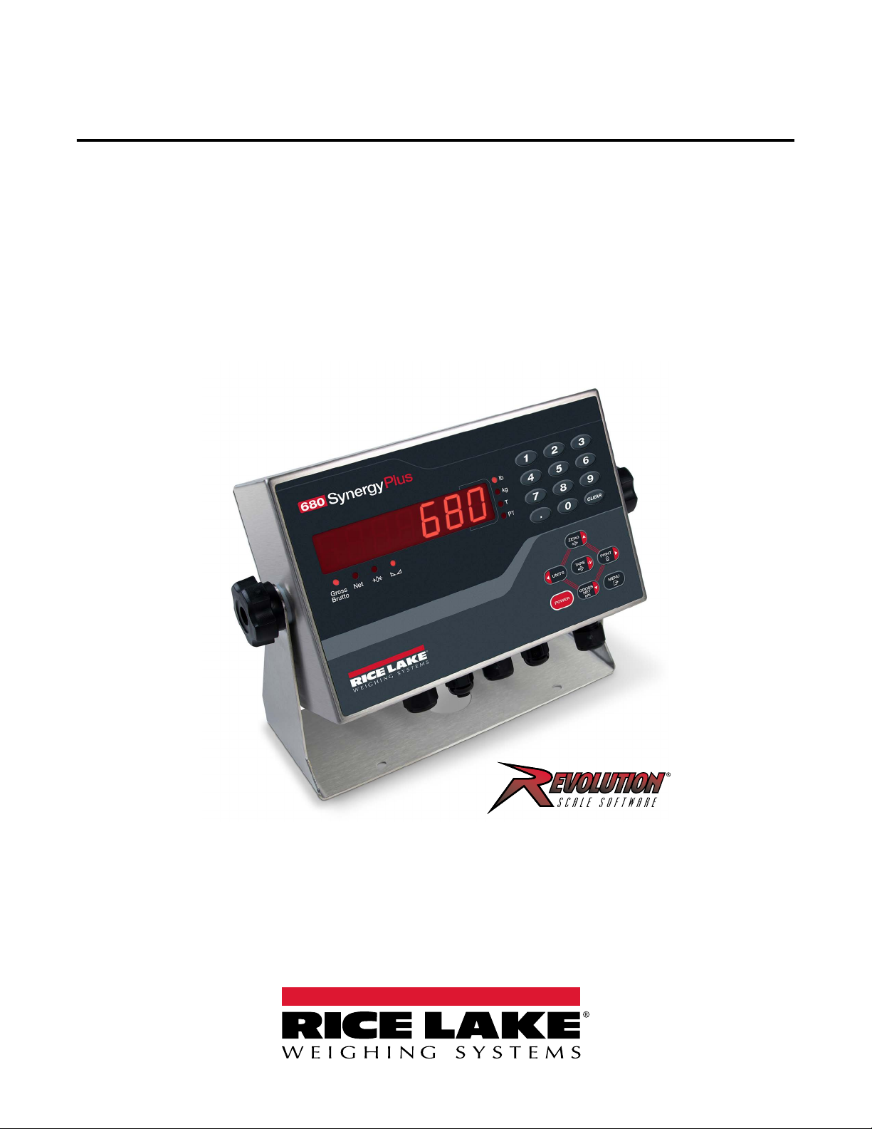
680 Synergy Plus
Digital Weight Indicator
Technical Manual
November 7, 2023 PN 192627 Rev N
Page 2

© Rice Lake Weighing Systems. All rights reserved.
Rice Lake Weighing Systems
®
is a registered trademark of
Rice Lake Weighing Systems.
All other brand or product names within this publication are trademarks or
registered trademarks of their respective companies.
All information contained within this publication is, to the best of our knowledge, complete and
accurate at the time of publication. Rice Lake Weighing Systems reserves the right to make
changes to the technology, features, specifications and design of the equipment without notice.
The most current version of this publication, software, firmware and all other product
updates can be found on our website:
www.ricelake.com
Page 3
Revision History
This section tracks and describes manual revisions for awareness of major updates.
Revision Date Description
– July 26, 2019 Initial manual release with the launch of the product; firmware version 1.0
L November 30, 2022 Revision history established; updates for RS-485/422, DC power, analog output configuration and approvals;
parameter updates made in the Configuration and EDP Commands chapters; firmware version 1.12
M December 22, 2022 Content addition for DC power cable and update to batching switch wiring; firmware version 1.12
N November 7, 2023 Added power cord details, updated serial scale input capacities, added CPU board updates
Table i. Revision Letter History
Revision History
Technical training seminars are available through Rice Lake Weighing Systems.
Course descriptions and dates can be viewed at www.ricelake.com/training
or obtained by calling 715-234-9171 and asking for the training department.
© Rice Lake Weighing Systems ● All Rights Reserved 3
Page 4
680 Synergy Plus
Contents
1.0 Introduction . . . . . . . . . . . . . . . . . . . . . . . . . . . . . . . . . . . . . . . . . . . . . . . . . . . . . . . . . . . . . . . . . . . . . . . . . . . . 7
1.1 Safety . . . . . . . . . . . . . . . . . . . . . . . . . . . . . . . . . . . . . . . . . . . . . . . . . . . . . . . . . . . . . . . . . . . . . . . . . . . . . . . . . . . . . . . . . . . . . 7
1.2 FCC Compliance. . . . . . . . . . . . . . . . . . . . . . . . . . . . . . . . . . . . . . . . . . . . . . . . . . . . . . . . . . . . . . . . . . . . . . . . . . . . . . . . . . . . . 8
1.3 Operating Modes. . . . . . . . . . . . . . . . . . . . . . . . . . . . . . . . . . . . . . . . . . . . . . . . . . . . . . . . . . . . . . . . . . . . . . . . . . . . . . . . . . . . . 8
1.4 Option Card. . . . . . . . . . . . . . . . . . . . . . . . . . . . . . . . . . . . . . . . . . . . . . . . . . . . . . . . . . . . . . . . . . . . . . . . . . . . . . . . . . . . . . . . . 8
1.5 RJ45 Option . . . . . . . . . . . . . . . . . . . . . . . . . . . . . . . . . . . . . . . . . . . . . . . . . . . . . . . . . . . . . . . . . . . . . . . . . . . . . . . . . . . . . . . . 8
2.0 Installation . . . . . . . . . . . . . . . . . . . . . . . . . . . . . . . . . . . . . . . . . . . . . . . . . . . . . . . . . . . . . . . . . . . . . . . . . . . . . 9
2.1 Unpacking . . . . . . . . . . . . . . . . . . . . . . . . . . . . . . . . . . . . . . . . . . . . . . . . . . . . . . . . . . . . . . . . . . . . . . . . . . . . . . . . . . . . . . . . . . 9
2.2 Product Dimensions . . . . . . . . . . . . . . . . . . . . . . . . . . . . . . . . . . . . . . . . . . . . . . . . . . . . . . . . . . . . . . . . . . . . . . . . . . . . . . . . . . 9
2.3 Mounting Instructions . . . . . . . . . . . . . . . . . . . . . . . . . . . . . . . . . . . . . . . . . . . . . . . . . . . . . . . . . . . . . . . . . . . . . . . . . . . . . . . . 10
2.4 Backplate Removal . . . . . . . . . . . . . . . . . . . . . . . . . . . . . . . . . . . . . . . . . . . . . . . . . . . . . . . . . . . . . . . . . . . . . . . . . . . . . . . . . . 11
2.5 Cable Connections . . . . . . . . . . . . . . . . . . . . . . . . . . . . . . . . . . . . . . . . . . . . . . . . . . . . . . . . . . . . . . . . . . . . . . . . . . . . . . . . . . 11
2.5.1 Cable Diameter Ranges. . . . . . . . . . . . . . . . . . . . . . . . . . . . . . . . . . . . . . . . . . . . . . . . . . . . . . . . . . . . . . . . . . . . . . . 12
2.5.2 Cable Shield Grounding . . . . . . . . . . . . . . . . . . . . . . . . . . . . . . . . . . . . . . . . . . . . . . . . . . . . . . . . . . . . . . . . . . . . . . . 12
2.5.3 Torque Ratings. . . . . . . . . . . . . . . . . . . . . . . . . . . . . . . . . . . . . . . . . . . . . . . . . . . . . . . . . . . . . . . . . . . . . . . . . . . . . . 13
2.5.4 AC Power . . . . . . . . . . . . . . . . . . . . . . . . . . . . . . . . . . . . . . . . . . . . . . . . . . . . . . . . . . . . . . . . . . . . . . . . . . . . . . . . . . 13
2.5.5 DC Power. . . . . . . . . . . . . . . . . . . . . . . . . . . . . . . . . . . . . . . . . . . . . . . . . . . . . . . . . . . . . . . . . . . . . . . . . . . . . . . . . . 13
2.5.6 Power Cable. . . . . . . . . . . . . . . . . . . . . . . . . . . . . . . . . . . . . . . . . . . . . . . . . . . . . . . . . . . . . . . . . . . . . . . . . . . . . . . . 14
2.5.7 Load Cell Cables . . . . . . . . . . . . . . . . . . . . . . . . . . . . . . . . . . . . . . . . . . . . . . . . . . . . . . . . . . . . . . . . . . . . . . . . . . . . 14
2.5.8 RS-232 Serial Communications . . . . . . . . . . . . . . . . . . . . . . . . . . . . . . . . . . . . . . . . . . . . . . . . . . . . . . . . . . . . . . . . . 15
2.5.9 RS-485/422 Serial Communications . . . . . . . . . . . . . . . . . . . . . . . . . . . . . . . . . . . . . . . . . . . . . . . . . . . . . . . . . . . . . 15
2.5.10 Digital I/O . . . . . . . . . . . . . . . . . . . . . . . . . . . . . . . . . . . . . . . . . . . . . . . . . . . . . . . . . . . . . . . . . . . . . . . . . . . . . . . . . . 15
2.5.11 Micro USB Device Communications . . . . . . . . . . . . . . . . . . . . . . . . . . . . . . . . . . . . . . . . . . . . . . . . . . . . . . . . . . . . . 16
2.5.12 Ethernet . . . . . . . . . . . . . . . . . . . . . . . . . . . . . . . . . . . . . . . . . . . . . . . . . . . . . . . . . . . . . . . . . . . . . . . . . . . . . . . . . . . 16
2.6 CPU Board . . . . . . . . . . . . . . . . . . . . . . . . . . . . . . . . . . . . . . . . . . . . . . . . . . . . . . . . . . . . . . . . . . . . . . . . . . . . . . . . . . . . . . . . 18
2.6.1 Option Card Port . . . . . . . . . . . . . . . . . . . . . . . . . . . . . . . . . . . . . . . . . . . . . . . . . . . . . . . . . . . . . . . . . . . . . . . . . . . . 18
2.6.2 Load Cell Compensation Jumper. . . . . . . . . . . . . . . . . . . . . . . . . . . . . . . . . . . . . . . . . . . . . . . . . . . . . . . . . . . . . . . . 18
2.7 Backplate Attachment . . . . . . . . . . . . . . . . . . . . . . . . . . . . . . . . . . . . . . . . . . . . . . . . . . . . . . . . . . . . . . . . . . . . . . . . . . . . . . . . 19
2.8 Sealing the Indicator (Optional). . . . . . . . . . . . . . . . . . . . . . . . . . . . . . . . . . . . . . . . . . . . . . . . . . . . . . . . . . . . . . . . . . . . . . . . . 19
2.9 Parts Kit Components . . . . . . . . . . . . . . . . . . . . . . . . . . . . . . . . . . . . . . . . . . . . . . . . . . . . . . . . . . . . . . . . . . . . . . . . . . . . . . . . 20
2.10 Replacement Parts . . . . . . . . . . . . . . . . . . . . . . . . . . . . . . . . . . . . . . . . . . . . . . . . . . . . . . . . . . . . . . . . . . . . . . . . . . . . . . . . . . 21
3.0 Operation . . . . . . . . . . . . . . . . . . . . . . . . . . . . . . . . . . . . . . . . . . . . . . . . . . . . . . . . . . . . . . . . . . . . . . . . . . . . . 25
3.1 Front Panel . . . . . . . . . . . . . . . . . . . . . . . . . . . . . . . . . . . . . . . . . . . . . . . . . . . . . . . . . . . . . . . . . . . . . . . . . . . . . . . . . . . . . . . . 25
3.2 LED Annunciators . . . . . . . . . . . . . . . . . . . . . . . . . . . . . . . . . . . . . . . . . . . . . . . . . . . . . . . . . . . . . . . . . . . . . . . . . . . . . . . . . . . 26
3.3 General Navigation . . . . . . . . . . . . . . . . . . . . . . . . . . . . . . . . . . . . . . . . . . . . . . . . . . . . . . . . . . . . . . . . . . . . . . . . . . . . . . . . . . 26
3.3.1 Numeric Value Entry . . . . . . . . . . . . . . . . . . . . . . . . . . . . . . . . . . . . . . . . . . . . . . . . . . . . . . . . . . . . . . . . . . . . . . . . . 26
3.3.2 Alphanumeric Entry . . . . . . . . . . . . . . . . . . . . . . . . . . . . . . . . . . . . . . . . . . . . . . . . . . . . . . . . . . . . . . . . . . . . . . . . . . 27
3.4 General Indicator Operation . . . . . . . . . . . . . . . . . . . . . . . . . . . . . . . . . . . . . . . . . . . . . . . . . . . . . . . . . . . . . . . . . . . . . . . . . . . 27
3.4.1 Zero Scale . . . . . . . . . . . . . . . . . . . . . . . . . . . . . . . . . . . . . . . . . . . . . . . . . . . . . . . . . . . . . . . . . . . . . . . . . . . . . . . . . 27
3.4.2 Print Ticket . . . . . . . . . . . . . . . . . . . . . . . . . . . . . . . . . . . . . . . . . . . . . . . . . . . . . . . . . . . . . . . . . . . . . . . . . . . . . . . . . 27
3.4.3 Toggle Units . . . . . . . . . . . . . . . . . . . . . . . . . . . . . . . . . . . . . . . . . . . . . . . . . . . . . . . . . . . . . . . . . . . . . . . . . . . . . . . . 27
3.4.4 Toggle Gross/Net Mode . . . . . . . . . . . . . . . . . . . . . . . . . . . . . . . . . . . . . . . . . . . . . . . . . . . . . . . . . . . . . . . . . . . . . . . 27
3.4.5 Acquire Tare. . . . . . . . . . . . . . . . . . . . . . . . . . . . . . . . . . . . . . . . . . . . . . . . . . . . . . . . . . . . . . . . . . . . . . . . . . . . . . . . 28
3.4.6 Remove Stored Tare Value . . . . . . . . . . . . . . . . . . . . . . . . . . . . . . . . . . . . . . . . . . . . . . . . . . . . . . . . . . . . . . . . . . . . 28
3.4.7 Preset Tare (Keyed Tare) . . . . . . . . . . . . . . . . . . . . . . . . . . . . . . . . . . . . . . . . . . . . . . . . . . . . . . . . . . . . . . . . . . . . . 28
3.4.8 Display a Stored Tare . . . . . . . . . . . . . . . . . . . . . . . . . . . . . . . . . . . . . . . . . . . . . . . . . . . . . . . . . . . . . . . . . . . . . . . . 28
Rice Lake continually offers web-based video training on a growing selection
of product-related topics at no cost. Visit www.ricelake.com/webinars
4 Visit our website www.RiceLake.com
Page 5

Contents
3.4.9 Clear a Stored Tare . . . . . . . . . . . . . . . . . . . . . . . . . . . . . . . . . . . . . . . . . . . . . . . . . . . . . . . . . . . . . . . . . . . . . . . . . . 28
3.4.10 View Audit Trail Counters. . . . . . . . . . . . . . . . . . . . . . . . . . . . . . . . . . . . . . . . . . . . . . . . . . . . . . . . . . . . . . . . . . . . . . 29
3.4.11 View Legally Relevant Version. . . . . . . . . . . . . . . . . . . . . . . . . . . . . . . . . . . . . . . . . . . . . . . . . . . . . . . . . . . . . . . . . . 29
3.4.12 Display Accumulator . . . . . . . . . . . . . . . . . . . . . . . . . . . . . . . . . . . . . . . . . . . . . . . . . . . . . . . . . . . . . . . . . . . . . . . . . 29
3.4.13 Print Accumulator. . . . . . . . . . . . . . . . . . . . . . . . . . . . . . . . . . . . . . . . . . . . . . . . . . . . . . . . . . . . . . . . . . . . . . . . . . . . 29
3.4.14 Clear Accumulator . . . . . . . . . . . . . . . . . . . . . . . . . . . . . . . . . . . . . . . . . . . . . . . . . . . . . . . . . . . . . . . . . . . . . . . . . . . 30
3.4.15 Enter New Unit ID . . . . . . . . . . . . . . . . . . . . . . . . . . . . . . . . . . . . . . . . . . . . . . . . . . . . . . . . . . . . . . . . . . . . . . . . . . . 30
3.4.16 View and Edit Time Value . . . . . . . . . . . . . . . . . . . . . . . . . . . . . . . . . . . . . . . . . . . . . . . . . . . . . . . . . . . . . . . . . . . . . 30
3.4.17 View and Edit Date Value . . . . . . . . . . . . . . . . . . . . . . . . . . . . . . . . . . . . . . . . . . . . . . . . . . . . . . . . . . . . . . . . . . . . . 31
3.4.18 View Configured Setpoint Values. . . . . . . . . . . . . . . . . . . . . . . . . . . . . . . . . . . . . . . . . . . . . . . . . . . . . . . . . . . . . . . . 31
3.4.19 Reset Configuration . . . . . . . . . . . . . . . . . . . . . . . . . . . . . . . . . . . . . . . . . . . . . . . . . . . . . . . . . . . . . . . . . . . . . . . . . . 31
4.0 Configuration . . . . . . . . . . . . . . . . . . . . . . . . . . . . . . . . . . . . . . . . . . . . . . . . . . . . . . . . . . . . . . . . . . . . . . . . . . 32
4.1 Setup Switch . . . . . . . . . . . . . . . . . . . . . . . . . . . . . . . . . . . . . . . . . . . . . . . . . . . . . . . . . . . . . . . . . . . . . . . . . . . . . . . . . . . . . . . 32
4.2 Main Menu . . . . . . . . . . . . . . . . . . . . . . . . . . . . . . . . . . . . . . . . . . . . . . . . . . . . . . . . . . . . . . . . . . . . . . . . . . . . . . . . . . . . . . . . 33
4.3 Audit Menu . . . . . . . . . . . . . . . . . . . . . . . . . . . . . . . . . . . . . . . . . . . . . . . . . . . . . . . . . . . . . . . . . . . . . . . . . . . . . . . . . . . . . . . . 33
4.4 Setup Menu. . . . . . . . . . . . . . . . . . . . . . . . . . . . . . . . . . . . . . . . . . . . . . . . . . . . . . . . . . . . . . . . . . . . . . . . . . . . . . . . . . . . . . . . 34
4.4.1 Configuration Menu . . . . . . . . . . . . . . . . . . . . . . . . . . . . . . . . . . . . . . . . . . . . . . . . . . . . . . . . . . . . . . . . . . . . . . . . . . 34
4.4.2 Format Menu . . . . . . . . . . . . . . . . . . . . . . . . . . . . . . . . . . . . . . . . . . . . . . . . . . . . . . . . . . . . . . . . . . . . . . . . . . . . . . . 36
4.4.3 Calibration Menu . . . . . . . . . . . . . . . . . . . . . . . . . . . . . . . . . . . . . . . . . . . . . . . . . . . . . . . . . . . . . . . . . . . . . . . . . . . . 36
4.4.4 Communication Menu . . . . . . . . . . . . . . . . . . . . . . . . . . . . . . . . . . . . . . . . . . . . . . . . . . . . . . . . . . . . . . . . . . . . . . . . 37
4.4.5 Program Menu . . . . . . . . . . . . . . . . . . . . . . . . . . . . . . . . . . . . . . . . . . . . . . . . . . . . . . . . . . . . . . . . . . . . . . . . . . . . . . 41
4.4.6 Print Format Menu . . . . . . . . . . . . . . . . . . . . . . . . . . . . . . . . . . . . . . . . . . . . . . . . . . . . . . . . . . . . . . . . . . . . . . . . . . . 44
4.4.7 Stream Format Menu . . . . . . . . . . . . . . . . . . . . . . . . . . . . . . . . . . . . . . . . . . . . . . . . . . . . . . . . . . . . . . . . . . . . . . . . . 45
4.4.8 Setpoints Menu . . . . . . . . . . . . . . . . . . . . . . . . . . . . . . . . . . . . . . . . . . . . . . . . . . . . . . . . . . . . . . . . . . . . . . . . . . . . . 46
4.4.9 Digital I/O Menu . . . . . . . . . . . . . . . . . . . . . . . . . . . . . . . . . . . . . . . . . . . . . . . . . . . . . . . . . . . . . . . . . . . . . . . . . . . . . 49
4.4.10 Analog Output Menu . . . . . . . . . . . . . . . . . . . . . . . . . . . . . . . . . . . . . . . . . . . . . . . . . . . . . . . . . . . . . . . . . . . . . . . . . 49
4.5 Accumulator Menu . . . . . . . . . . . . . . . . . . . . . . . . . . . . . . . . . . . . . . . . . . . . . . . . . . . . . . . . . . . . . . . . . . . . . . . . . . . . . . . . . . 50
4.6 Tare Menu. . . . . . . . . . . . . . . . . . . . . . . . . . . . . . . . . . . . . . . . . . . . . . . . . . . . . . . . . . . . . . . . . . . . . . . . . . . . . . . . . . . . . . . . . 50
5.0 Calibration . . . . . . . . . . . . . . . . . . . . . . . . . . . . . . . . . . . . . . . . . . . . . . . . . . . . . . . . . . . . . . . . . . . . . . . . . . . . 51
5.1 Front Panel Calibration . . . . . . . . . . . . . . . . . . . . . . . . . . . . . . . . . . . . . . . . . . . . . . . . . . . . . . . . . . . . . . . . . . . . . . . . . . . . . . . 51
5.1.1 Span Calibration. . . . . . . . . . . . . . . . . . . . . . . . . . . . . . . . . . . . . . . . . . . . . . . . . . . . . . . . . . . . . . . . . . . . . . . . . . . . . 51
5.1.2 Linear Calibration . . . . . . . . . . . . . . . . . . . . . . . . . . . . . . . . . . . . . . . . . . . . . . . . . . . . . . . . . . . . . . . . . . . . . . . . . . . . 52
5.2 Alternative Zero Calibrations. . . . . . . . . . . . . . . . . . . . . . . . . . . . . . . . . . . . . . . . . . . . . . . . . . . . . . . . . . . . . . . . . . . . . . . . . . . 52
5.2.1 Last Zero . . . . . . . . . . . . . . . . . . . . . . . . . . . . . . . . . . . . . . . . . . . . . . . . . . . . . . . . . . . . . . . . . . . . . . . . . . . . . . . . . . 52
5.2.2 Temporary Zero . . . . . . . . . . . . . . . . . . . . . . . . . . . . . . . . . . . . . . . . . . . . . . . . . . . . . . . . . . . . . . . . . . . . . . . . . . . . . 52
5.2.3 Rezero . . . . . . . . . . . . . . . . . . . . . . . . . . . . . . . . . . . . . . . . . . . . . . . . . . . . . . . . . . . . . . . . . . . . . . . . . . . . . . . . . . . . 52
5.3 EDP Command Calibration . . . . . . . . . . . . . . . . . . . . . . . . . . . . . . . . . . . . . . . . . . . . . . . . . . . . . . . . . . . . . . . . . . . . . . . . . . . . 53
6.0 Revolution . . . . . . . . . . . . . . . . . . . . . . . . . . . . . . . . . . . . . . . . . . . . . . . . . . . . . . . . . . . . . . . . . . . . . . . . . . . . 54
6.1 Connecting to the Indicator . . . . . . . . . . . . . . . . . . . . . . . . . . . . . . . . . . . . . . . . . . . . . . . . . . . . . . . . . . . . . . . . . . . . . . . . . . . . 54
6.2 Saving and Transferring Data . . . . . . . . . . . . . . . . . . . . . . . . . . . . . . . . . . . . . . . . . . . . . . . . . . . . . . . . . . . . . . . . . . . . . . . . . . 54
6.2.1 Saving Indicator Data to a Personal Computer . . . . . . . . . . . . . . . . . . . . . . . . . . . . . . . . . . . . . . . . . . . . . . . . . . . . . 54
6.2.2 Downloading Configuration Data from PC to Indicator . . . . . . . . . . . . . . . . . . . . . . . . . . . . . . . . . . . . . . . . . . . . . . . 54
6.3 Updating Firmware . . . . . . . . . . . . . . . . . . . . . . . . . . . . . . . . . . . . . . . . . . . . . . . . . . . . . . . . . . . . . . . . . . . . . . . . . . . . . . . . . . 54
7.0 EDP Commands. . . . . . . . . . . . . . . . . . . . . . . . . . . . . . . . . . . . . . . . . . . . . . . . . . . . . . . . . . . . . . . . . . . . . . . . 55
7.1 Key Press Commands . . . . . . . . . . . . . . . . . . . . . . . . . . . . . . . . . . . . . . . . . . . . . . . . . . . . . . . . . . . . . . . . . . . . . . . . . . . . . . . 55
7.2 Reporting Commands . . . . . . . . . . . . . . . . . . . . . . . . . . . . . . . . . . . . . . . . . . . . . . . . . . . . . . . . . . . . . . . . . . . . . . . . . . . . . . . . 56
7.3 Reset Configuration Command. . . . . . . . . . . . . . . . . . . . . . . . . . . . . . . . . . . . . . . . . . . . . . . . . . . . . . . . . . . . . . . . . . . . . . . . . 56
Technical training seminars are available through Rice Lake Weighing Systems.
Course descriptions and dates can be viewed at www.ricelake.com/training
or obtained by calling 715-234-9171 and asking for the training department.
© Rice Lake Weighing Systems ● All Rights Reserved 5
Page 6
680 Synergy Plus
7.4 Scale Parameter Setting Commands . . . . . . . . . . . . . . . . . . . . . . . . . . . . . . . . . . . . . . . . . . . . . . . . . . . . . . . . . . . . . . . . . . . . 57
7.5 Serial Port Setting Commands . . . . . . . . . . . . . . . . . . . . . . . . . . . . . . . . . . . . . . . . . . . . . . . . . . . . . . . . . . . . . . . . . . . . . . . . . 58
7.6 Ethernet and USB Setting Commands . . . . . . . . . . . . . . . . . . . . . . . . . . . . . . . . . . . . . . . . . . . . . . . . . . . . . . . . . . . . . . . . . . . 58
7.7 Stream Setting Commands . . . . . . . . . . . . . . . . . . . . . . . . . . . . . . . . . . . . . . . . . . . . . . . . . . . . . . . . . . . . . . . . . . . . . . . . . . . . 59
7.8 Program Commands . . . . . . . . . . . . . . . . . . . . . . . . . . . . . . . . . . . . . . . . . . . . . . . . . . . . . . . . . . . . . . . . . . . . . . . . . . . . . . . . . 60
7.9 Regulatory Commands . . . . . . . . . . . . . . . . . . . . . . . . . . . . . . . . . . . . . . . . . . . . . . . . . . . . . . . . . . . . . . . . . . . . . . . . . . . . . . . 60
7.10 Setpoint Commands . . . . . . . . . . . . . . . . . . . . . . . . . . . . . . . . . . . . . . . . . . . . . . . . . . . . . . . . . . . . . . . . . . . . . . . . . . . . . . . . . 61
7.11 Print Format Commands . . . . . . . . . . . . . . . . . . . . . . . . . . . . . . . . . . . . . . . . . . . . . . . . . . . . . . . . . . . . . . . . . . . . . . . . . . . . . . 62
7.12 Digital I/O Commands . . . . . . . . . . . . . . . . . . . . . . . . . . . . . . . . . . . . . . . . . . . . . . . . . . . . . . . . . . . . . . . . . . . . . . . . . . . . . . . . 62
7.13 Analog Output Commands . . . . . . . . . . . . . . . . . . . . . . . . . . . . . . . . . . . . . . . . . . . . . . . . . . . . . . . . . . . . . . . . . . . . . . . . . . . . 62
7.14 Weigh Mode Commands. . . . . . . . . . . . . . . . . . . . . . . . . . . . . . . . . . . . . . . . . . . . . . . . . . . . . . . . . . . . . . . . . . . . . . . . . . . . . . 63
7.15 Batching Control Commands . . . . . . . . . . . . . . . . . . . . . . . . . . . . . . . . . . . . . . . . . . . . . . . . . . . . . . . . . . . . . . . . . . . . . . . . . . 63
8.0 Print Formatting. . . . . . . . . . . . . . . . . . . . . . . . . . . . . . . . . . . . . . . . . . . . . . . . . . . . . . . . . . . . . . . . . . . . . . . . 64
8.1 Print Formatting Tokens . . . . . . . . . . . . . . . . . . . . . . . . . . . . . . . . . . . . . . . . . . . . . . . . . . . . . . . . . . . . . . . . . . . . . . . . . . . . . . 64
8.2 Customizing Print Formats . . . . . . . . . . . . . . . . . . . . . . . . . . . . . . . . . . . . . . . . . . . . . . . . . . . . . . . . . . . . . . . . . . . . . . . . . . . . 66
8.3 Non-Human Readable Characters . . . . . . . . . . . . . . . . . . . . . . . . . . . . . . . . . . . . . . . . . . . . . . . . . . . . . . . . . . . . . . . . . . . . . . 66
9.0 Setpoints . . . . . . . . . . . . . . . . . . . . . . . . . . . . . . . . . . . . . . . . . . . . . . . . . . . . . . . . . . . . . . . . . . . . . . . . . . . . . 67
9.1 Batch and Continuous Setpoints. . . . . . . . . . . . . . . . . . . . . . . . . . . . . . . . . . . . . . . . . . . . . . . . . . . . . . . . . . . . . . . . . . . . . . . . 67
9.2 Batch Operations . . . . . . . . . . . . . . . . . . . . . . . . . . . . . . . . . . . . . . . . . . . . . . . . . . . . . . . . . . . . . . . . . . . . . . . . . . . . . . . . . . . 69
9.3 Batching Switch. . . . . . . . . . . . . . . . . . . . . . . . . . . . . . . . . . . . . . . . . . . . . . . . . . . . . . . . . . . . . . . . . . . . . . . . . . . . . . . . . . . . . 69
9.4 Batching Examples . . . . . . . . . . . . . . . . . . . . . . . . . . . . . . . . . . . . . . . . . . . . . . . . . . . . . . . . . . . . . . . . . . . . . . . . . . . . . . . . . . 71
9.4.1 Example 1 . . . . . . . . . . . . . . . . . . . . . . . . . . . . . . . . . . . . . . . . . . . . . . . . . . . . . . . . . . . . . . . . . . . . . . . . . . . . . . . . . 71
9.4.2 Example 2 . . . . . . . . . . . . . . . . . . . . . . . . . . . . . . . . . . . . . . . . . . . . . . . . . . . . . . . . . . . . . . . . . . . . . . . . . . . . . . . . . 72
10.0 Maintenance. . . . . . . . . . . . . . . . . . . . . . . . . . . . . . . . . . . . . . . . . . . . . . . . . . . . . . . . . . . . . . . . . . . . . . . . . . . 73
10.1 Maintenance Checkpoints. . . . . . . . . . . . . . . . . . . . . . . . . . . . . . . . . . . . . . . . . . . . . . . . . . . . . . . . . . . . . . . . . . . . . . . . . . . . . 73
10.2 Field Wiring . . . . . . . . . . . . . . . . . . . . . . . . . . . . . . . . . . . . . . . . . . . . . . . . . . . . . . . . . . . . . . . . . . . . . . . . . . . . . . . . . . . . . . . . 73
10.3 Troubleshooting Tips. . . . . . . . . . . . . . . . . . . . . . . . . . . . . . . . . . . . . . . . . . . . . . . . . . . . . . . . . . . . . . . . . . . . . . . . . . . . . . . . . 73
10.4 Battery Replacement. . . . . . . . . . . . . . . . . . . . . . . . . . . . . . . . . . . . . . . . . . . . . . . . . . . . . . . . . . . . . . . . . . . . . . . . . . . . . . . . . 74
10.5 Board Replacement . . . . . . . . . . . . . . . . . . . . . . . . . . . . . . . . . . . . . . . . . . . . . . . . . . . . . . . . . . . . . . . . . . . . . . . . . . . . . . . . . 75
11.0 Appendix . . . . . . . . . . . . . . . . . . . . . . . . . . . . . . . . . . . . . . . . . . . . . . . . . . . . . . . . . . . . . . . . . . . . . . . . . . . . . 76
11.1 Error Messages. . . . . . . . . . . . . . . . . . . . . . . . . . . . . . . . . . . . . . . . . . . . . . . . . . . . . . . . . . . . . . . . . . . . . . . . . . . . . . . . . . . . . 76
11.2 ZZ EDP Command . . . . . . . . . . . . . . . . . . . . . . . . . . . . . . . . . . . . . . . . . . . . . . . . . . . . . . . . . . . . . . . . . . . . . . . . . . . . . . . . . . 76
11.3 Continuous Data (Stream) Output Formats. . . . . . . . . . . . . . . . . . . . . . . . . . . . . . . . . . . . . . . . . . . . . . . . . . . . . . . . . . . . . . . . 77
11.4 Custom Stream Formatting . . . . . . . . . . . . . . . . . . . . . . . . . . . . . . . . . . . . . . . . . . . . . . . . . . . . . . . . . . . . . . . . . . . . . . . . . . . . 79
11.5 Audit Trail Support . . . . . . . . . . . . . . . . . . . . . . . . . . . . . . . . . . . . . . . . . . . . . . . . . . . . . . . . . . . . . . . . . . . . . . . . . . . . . . . . . . 81
11.6 Conversion Factors for Secondary Units. . . . . . . . . . . . . . . . . . . . . . . . . . . . . . . . . . . . . . . . . . . . . . . . . . . . . . . . . . . . . . . . . . 81
11.7 Digital Filtering . . . . . . . . . . . . . . . . . . . . . . . . . . . . . . . . . . . . . . . . . . . . . . . . . . . . . . . . . . . . . . . . . . . . . . . . . . . . . . . . . . . . . 81
11.7.1 Digital Rolling Average Filter (AVGONLY) . . . . . . . . . . . . . . . . . . . . . . . . . . . . . . . . . . . . . . . . . . . . . . . . . . . . . . . . . 81
11.7.2 Adaptive Filter (ADPONLY) . . . . . . . . . . . . . . . . . . . . . . . . . . . . . . . . . . . . . . . . . . . . . . . . . . . . . . . . . . . . . . . . . . . . 82
11.7.3 Damping Filter (DMPONLY). . . . . . . . . . . . . . . . . . . . . . . . . . . . . . . . . . . . . . . . . . . . . . . . . . . . . . . . . . . . . . . . . . . . 83
11.8 Regulatory Mode Functions . . . . . . . . . . . . . . . . . . . . . . . . . . . . . . . . . . . . . . . . . . . . . . . . . . . . . . . . . . . . . . . . . . . . . . . . . . . 84
11.9 ASCII Character Chart . . . . . . . . . . . . . . . . . . . . . . . . . . . . . . . . . . . . . . . . . . . . . . . . . . . . . . . . . . . . . . . . . . . . . . . . . . . . . . . 85
11.10 Front Panel Display Characters . . . . . . . . . . . . . . . . . . . . . . . . . . . . . . . . . . . . . . . . . . . . . . . . . . . . . . . . . . . . . . . . . . . . . . . . 86
12.0 Compliance . . . . . . . . . . . . . . . . . . . . . . . . . . . . . . . . . . . . . . . . . . . . . . . . . . . . . . . . . . . . . . . . . . . . . . . . . . . 87
13.0 Specifications . . . . . . . . . . . . . . . . . . . . . . . . . . . . . . . . . . . . . . . . . . . . . . . . . . . . . . . . . . . . . . . . . . . . . . . . . 89
Rice Lake continually offers web-based video training on a growing selection
of product-related topics at no cost. Visit www.ricelake.com/webinars
6 Visit our website www.RiceLake.com
Page 7
Introduction
i
1.0 Introduction
This manual is intended for use by service technicians responsible for installing and servicing 680 digital weight indicators.
®
Configuration and calibration of the indicator can be accomplished using the Revolution
front panel keys. See Section 4.0 on page 32 and Section 5.0 on page 51 for information about configuration and calibration.
configuration utility or the indicator
Manuals are available from Rice Lake Weighing Systems at
www.ricelake.com/manuals
Warranty information is available at www.ricelake.com/warranties
1.1 Safety
Safety Definitions:
DANGER: Indicates an imminently hazardous situation that, if not avoided, will result in death or serious injury. Includes
hazards that are exposed when guards are removed.
WARNING: Indicates a potentially hazardous situation that, if not avoided, could result in serious injury or death. Includes
hazards that are exposed when guards are removed.
CAUTION: Indicates a potentially hazardous situation that, if not avoided, could result in minor or moderate injury.
IMPORTANT: Indicates information about procedures that, if not observed, could result in damage to equipment or
corruption to and loss of data.
General Safety
Do not operate or work on this equipment unless this manual has been read and all instructions are understood.
Failure to follow the instructions or heed the warnings could result in injury or death. Contact any Rice Lake
Weighing Systems dealer for replacement manuals.
WARNING: Failure to heed could result in serious injury or death.
Some procedures described in this manual require work inside the indicator enclosure. These procedures are to be performed by
qualified service personnel only.
Ensure the power cord is disconnected from the outlet before opening the unit.
Do not allow minors (children) or inexperienced persons to operate this unit.
Do not operate without the enclosure completely assembled.
Do not use for purposes other than weight taking.
Do not place fingers into slots or possible pinch points.
Do not use this product if any of the components are cracked.
Do not exceed the rated specification of the unit.
Only connect unit to equipment certified to IEC 60950, IEC 62368, IEC 61010 or similar.
Do not make alterations or modifications to the unit.
Do not remove or obscure warning labels.
Do not use solvents or aggressive substances to clean the indicator.
Do not submerge.
© Rice Lake Weighing Systems ● All Rights Reserved 7
Page 8

680 Synergy Plus
1.2 FCC Compliance
United States
This equipment has been tested and found to comply with the limits for a Class A digital device, pursuant to Part 15 of the FCC
Rules. These limits are designed to provide reasonable protection against harmful interference when the equipment is operated
in a commercial environment. This equipment generates, uses, and can radiate radio frequency energy and, if not installed and
used in accordance with the instruction manual, may cause harmful interference to radio communications. Operation of this
equipment in a residential area is likely to cause harmful interference in which case the user will be required to correct the
interference at his own expense.
Canada
This digital apparatus does not exceed the Class A limits for radio noise emissions from digital apparatus set out in the Radio
Interference Regulations of the Canadian Department of Communications.
Le présent appareil numérique n'émet pas de bruits radioélectriques dépassant les limites applicables aux appareils
numériques de la Class A prescites dans le Règlement sur le brouillage radioélectrique edicté par le ministère des
Communications du Canada.
1.3 Operating Modes
Weigh Mode
Weigh mode is the default mode of the indicator. The indicator displays gross or net weights as required, using the annunciators
to indicate scale status and the type of weight value displayed.
User Mode
User mode is accessible by pressing on the front panel. The indicator displays the audit, accumulator, tare and version
menus when in user mode.
Setup Mode
Most of the procedures described in this manual, including calibration, require the indicator to be in setup mode.
See Section 4.0 on page 32 for the procedure to enter setup mode and the parameters available.
1.4 Option Card
The 680 has a single option card slot which can support the Synergy Series Single Analog Output Option Card (PN 195084).
The Synergy Series Single Analog Output Option Card kit includes instructions for installation and setup.
1.5 RJ45 Option
The 680 is available with an external RJ45 option. This external RJ45 connector is located on the backplate of the 680 and
provides quick access to the Ethernet TCP/IP 10Base-T/100Base-TX communication (Section 2.5.12 on page 16). 680
indicators without the RJ45 option access Ethernet using the J8 connector on the CPU board inside of the enclosure.
8 Visit our website www.RiceLake.com
Page 9
2.0 Installation
A
C
F
E
B
D
G
Installation
This section describes procedures for connecting power, load cells, digital I/O and data communication cables to a 680 indicator.
An assembly drawing and parts list are included for the service technician.
WARNING
AVERTISSEMENT
CAUTION: Risk of explosion if battery is replaced by an incorrect type. Dispose of used batteries according to state and
local regulations.
ATTENTION: Risque d’explosion si la batterie est remplacée par un type incorrect. Mattre au rebus les batteries usagées
selon les règlements d'état et locaux.
WARNING: Failure to heed the following statements could result in serious injury or death.
• Procedures requiring work inside the product enclosure must be performed by qualified service personnel only.
• Use a grounding wrist strap to protect components from electrostatic discharge (ESD) damage when working inside the
product enclosure.
• The power outlet must be near the equipment and must be easily accessible.
Risk of electrical shock.
Risque de choc.
Disconnect power before servicing.
Débranchez l’alimentation avant l’entretien.
2.1 Unpacking
Immediately after unpacking, visually inspect the 680 to ensure all components are included and undamaged. The shipping
carton contains the indicator, this manual and a parts kit (Section 2.9 on page 20). If parts were damaged in shipment, notify
Rice Lake Weighing Systems and the shipper immediately.
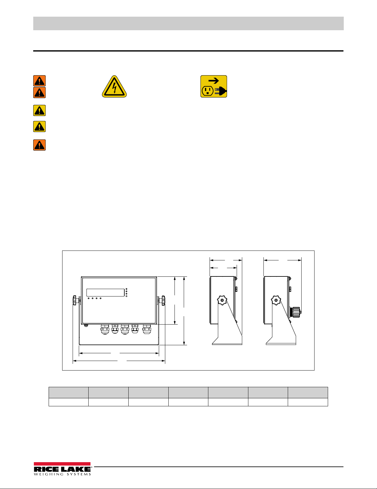
2.2 Product Dimensions
680 with Optional
RJ45 Connector
Figure 2-1. Product Diagram
A B C D E F G
10.02'' (254.5 mm) 11.58'' (294.1 mm) 6.00'' (152.4 mm) 8.57'' (217.7 mm) 3.40'' (86.4 mm) 4.05'' (102.9 mm) 4.74'' (120.4 mm)
Table 2-1. Product Dimensions
© Rice Lake Weighing Systems ● All Rights Reserved 9
Page 10
680 Synergy Plus
6.00
"
(152.4
mm
)
3.01
"
(76.5
mm
)
2.01
"
(51.1
mm
)
4X Ø 0.28
"
(4X Ø 7.1
mm
)
0.37
"
(9.4
mm
)
1.51
"
(38.4
mm
)
3.00
"
(76.2
mm
)
Ø 1.50
"
(Ø 38.1
mm
)
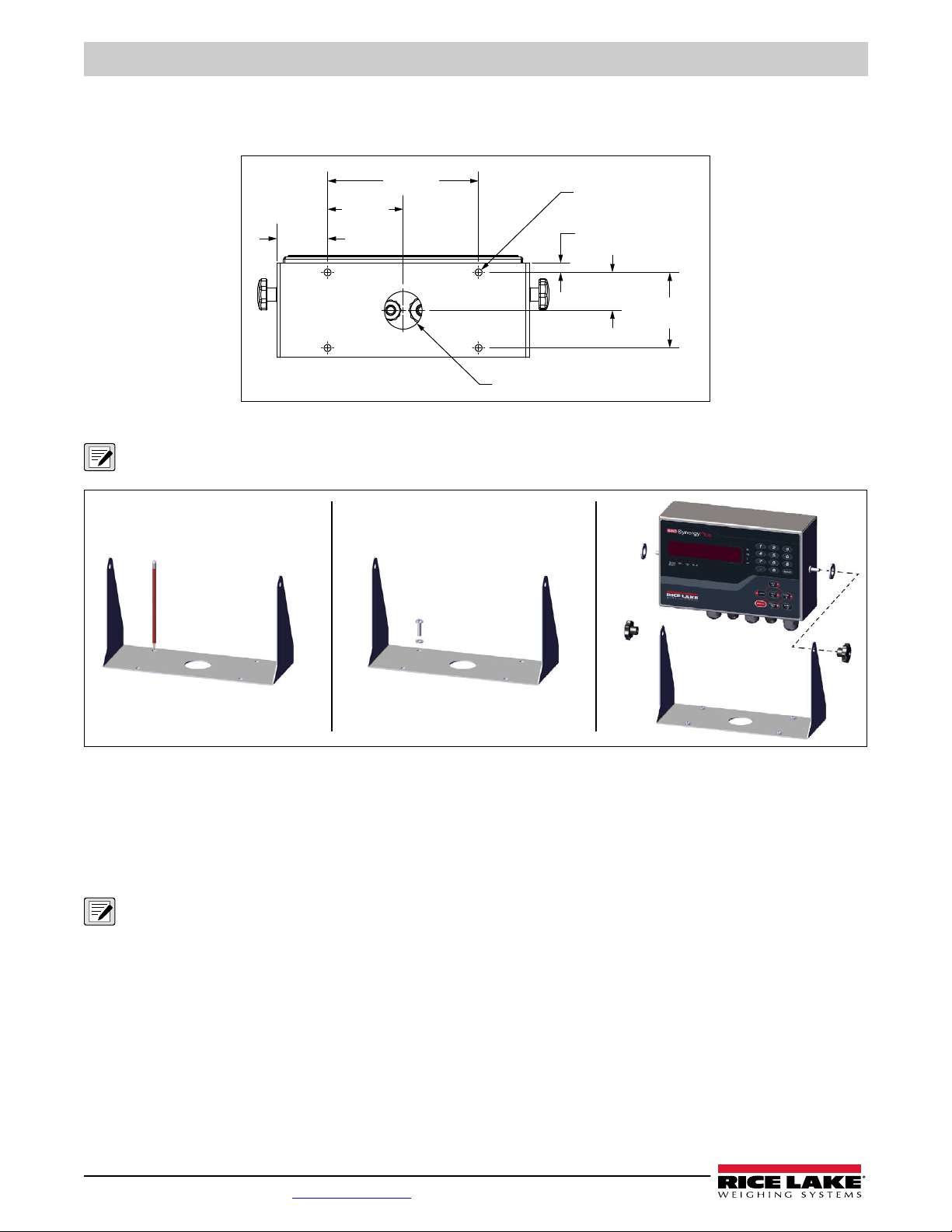
2.3 Mounting Instructions
The 680 includes a universal mount stand. The stand can be mounted on a wall, tabletop or a flat surface.
Figure 2-2. Mounting Dimensions
NOTE: The universal mount stand comes attached to the 680. Rice Lake Weighing Systems recommends removing the 680
from the stand prior to mounting.
1. Using the mount as a template, mark the screw locations.
2. Drill holes for the screws.
3. Secure the universal mount using the appropriate length 1/4'' or M6 hardware (not included).
4. Reattach the 680 to the universal mount stand.
NOTE: The parts kit includes rubber grommets to insert into the four screw holes of the universal mount stand for a
non-mounted application.
10 Visit our website www.RiceLake.com
Figure 2-3. Mounting the Indicator
Page 11
2.4 Backplate Removal
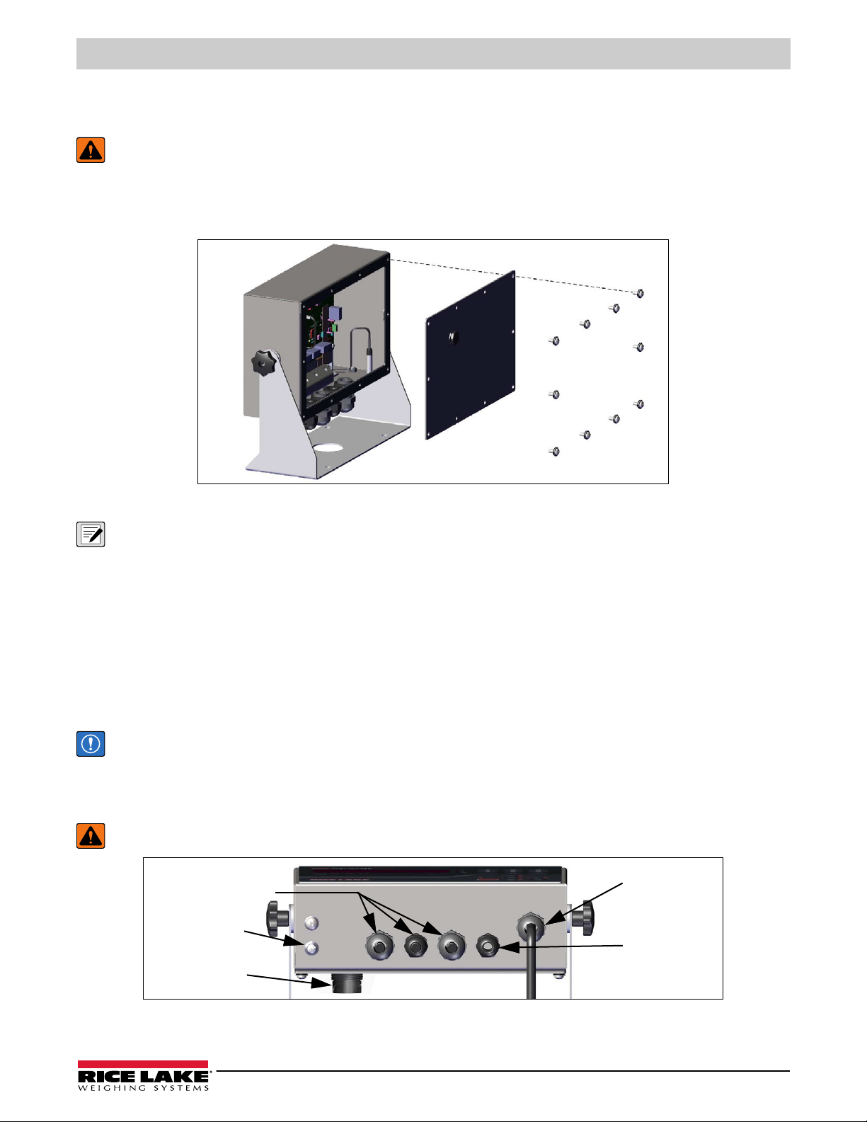
Remove the backplate of the 680 to connect cables and to gain access to the 680 board and power supply.
WARNING: Before opening the unit, ensure the power cord is disconnected from the power outlet.
1. Place the 680 face-down on an anti-static work mat.
2. Remove the screws holding the backplate to the enclosure.
3. Lift the backplate away from the enclosure and disconnect the ground wire from the backplate.
Installation
Figure 2-4. Removing the Backplate
NOTE: The 680 ships with only four screws securing the backplate. The remaining backplate screws are included in the
parts kit. For reassembly, torque backplate screws to 12 in-lb (1.3 N-m).
2.5 Cable Connections
The 680 provides five cord grips at the bottom of the enclosure for cabling into the indicator. One of the cord grips is used for
the power supply and the other four are used to accommodate the load cell cable and the serial, digital inputs and outputs,
Ethernet, micro USB or the optional analog output communications cables. A version of the 680 with an external RJ45
connector and cap is available. Cable plugs are included in the parts kit and must be installed in open cord grips to prevent
moisture from entering the enclosure. Use the attached cap to seal the optional RJ45 connector when not in use. See the
following sections to install cables as required for the application. The recommended cable strip length is 0.25'' (7 mm) for all
680 connectors. See Figure 2-5 for the recommended assignments for the 680 cord grips.
IMPORTANT: Do not have open/bare wires outside of the enclosure. Make sure stripped portion of cable is entirely inside
the cord grips.
IMPORTANT: Properly seal cord grips to prevent moisture damage inside of the enclosure. Cable plugs must be installed in
unused cord grips. Cord grip dome nuts, around a cable or a plug, must be torqued to 22 in-lb (2.5 N-m). The cord grip nut
against the enclosure must be torqued to 33 in-lb (3.7 N-m).
WARNING: Only connect unit to equipment certified to IEC 60950, IEC 62368, IEC 61010 or similar.
Cord grips for
communication cables
Access screw
for setup switch
RJ45 connector
(available option)
Power cord
Cord grip for
load cell cable
Figure 2-5. Recommended Cord Grip Assignments
© Rice Lake Weighing Systems ● All Rights Reserved 11
Page 12
680 Synergy Plus
2.5.1 Cable Diameter Ranges
Refer to Table 2-2 for minimum and maximum cable diameter sizes for use with 680 cord grips.
Cord Grip Diameter Range
PG9 (PN 15626) 0.138-0.315 in (3.5-8 mm)
PG11 (PN 68600) 0.197-0.394 in (5-10 mm)
Table 2-2. Cord Grip Cable Diameter Ranges
2.5.2 Cable Shield Grounding
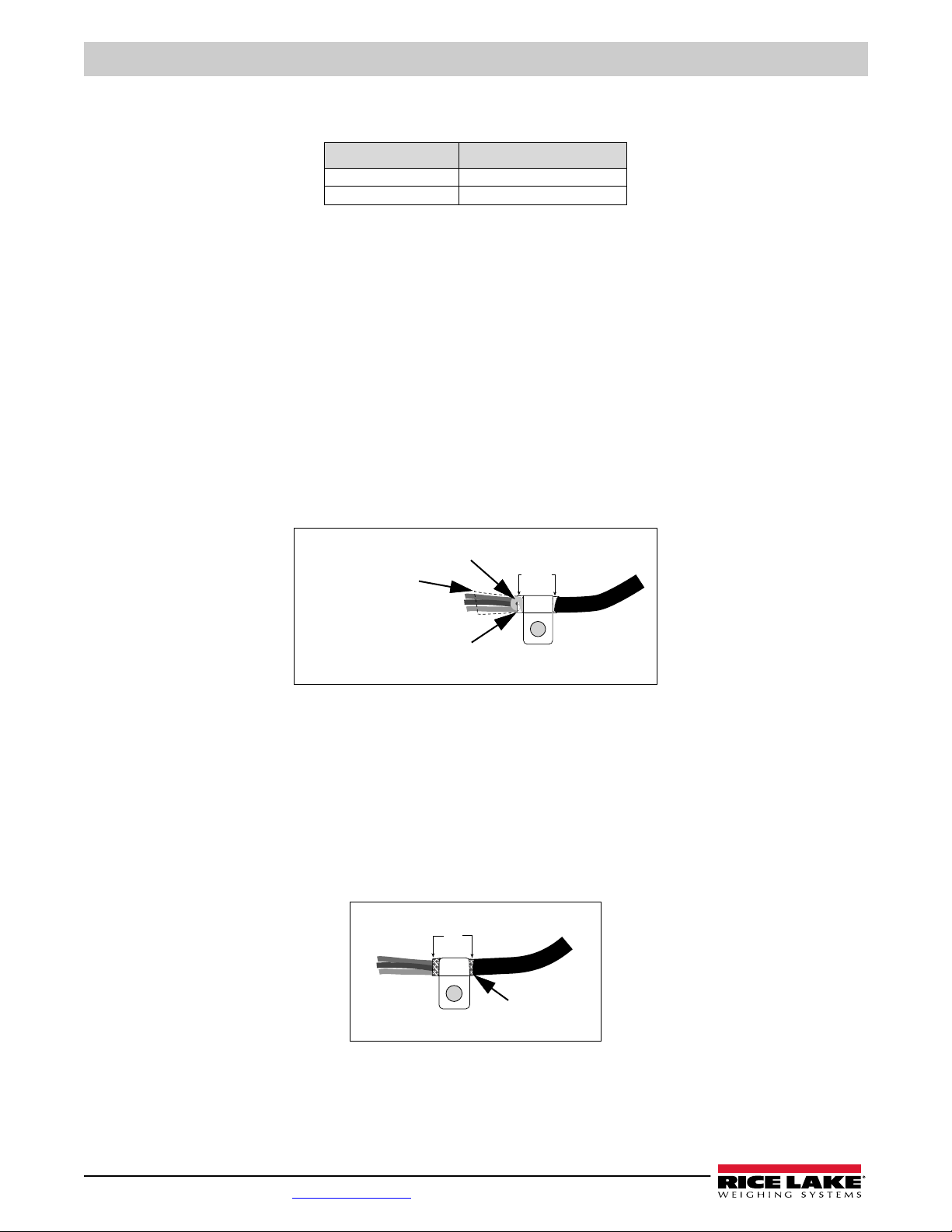
Except for the power cord, all cables routed through the cord grips must be shield grounded against the enclosure.
• Use hardware provided in the parts kit to install shielding clamps on the grounding bracket at the bottom of the enclosure
• Install only the necessary amount of shielding clamps for the cord grips to be used
• Remove the insulated jackets and shielding per the following instructions
Shielding Procedure
1. Install the shielding clamps on the grounding rail using the clamp screws. Finger tighten the screws at this time.
2. Route the cables through the cord grips and the shielding clamps to determine the cable lengths required to reach the
appropriate cable connectors.
3. Mark cables to remove the insulated jacket as described below for Foil Shielded Cables and Braid Shielded Cables.
Foil Shielded Cables
Shield wire
Length of foil before
folding back on
cable insulation
Cut insulated jacket here
for foil shielded cables
Figure 2-6. Foil Shielded Cable
Silver
side out
1. Strip the insulated jacket and foil 1/2'' (15 mm) past the shielding clamp.
2. Strip another 1/2'' of the insulated jacket, leaving the foil shielding exposed.
3. Fold the foil shielding back on the cable where the cable passes through the clamp.
4. Ensure the silver (conductive) side of the foil is turned outward.
5. Wrap the shield wire around the cable, ensuring it contacts the foil where the cable passes through the clamp.
6. Torque shielding clamp screw to 10 in-lb (1.1 N-m), ensuring clamp is around the cable and contacting the shield wire.
Braid Shielded Cables
Braid
Cut insulated
jacket here
Figure 2-7. Braid Shielded Cable
1. Strip the insulated jacket and braided shielding from a point just past the shielding clamp.
2. Strip another 1/2'' (15 mm) of the insulated jacket, leaving the braid exposed where the cable passes through the clamp.
3. Torque shielding clamp screw to 10 in-lb (1.1 N-m), ensuring the clamp is contacting the braided shielding of the cable.
12 Visit our website www.RiceLake.com
Page 13
2.5.3 Torque Ratings
I/P
1
2
3
1
2
O/P
LED
Refer to Table 2-3 throughout installation and use of product to maintain proper torque ratings for 680 components.
Component Torque Rating
Backplate Screw 12 in-lb (1.3 N-m)
Setup Screw 10 in-lb (1.1 N-m)
Cord Grip Nut (to enclosure) 33 in-lb (3.7 N-m)
Cord Grip Dome Nut (around cable) 22 in-lb (2.5 N-m)
Optional RJ45 Panel Nut 20 in-lb (2.3 N-m)
Table 2-3. Component Torque Ratings
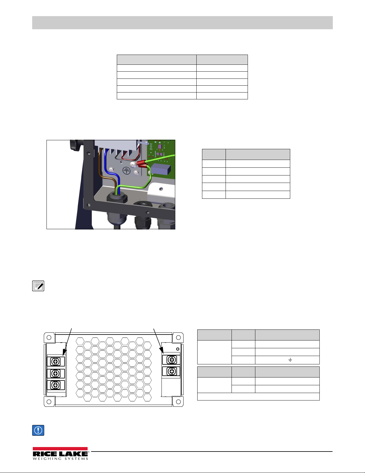
2.5.4 AC Power
AC models of the 680 are shipped with the power supply cable already installed and grounded to the enclosure.
Pin Function
1 120 VAC (Line In)
2 AC Neutral
3 Not Used
4 DC Out (-V)
5 DC Out (+V)
Table 2-4. AC Power Pin Assignments
Installation
Figure 2-8. Pre-installed AC Power Wiring
2.5.5 DC Power
DC models of the 680 do not include a power supply cable. Use the following steps to ground and connect a DC power cable.
1. Insert a 3-wire power cable (not included) into the enclosure through the power cable cord grip (
NOTE: The recommended wire gauge range for the power supply cable is 8-18 AWG. The recommended cable strip length
is 0.25'' (7 mm) for all 680 connectors. See Section 2.5.3 for proper torque ratings for the power cable cord grip and
Section 2.5.1 on page 12 for the allowed cable diameter range.
2. Connect the three wires of the power cable to the DC power supply board input screw terminal (I/P). See
the input terminal (I/P) pin assignments.
DC Power Input
Figure 2-9. DC Power Supply Board (PN 209417)
DC Power Output
Connector Pin Function
Input Terminal
(I/P)
1 DC Input V+
2 DC Input V3
Connector Pin Function
Output Terminal
(O/P)
Pre-installed wiring connects power supply board to CPU board.
1 DC Output V2 DC Output V+
Table 2-5. DC Power Pin Assignments
Figure 2-5 on page 11
Table 2-5
Ground (FG)
for
).
IMPORTANT: A 3-wire power cable is required and the ground wire must be connected to the specified pin assignment on
the DC power supply board.
© Rice Lake Weighing Systems ● All Rights Reserved 13
Page 14
680 Synergy Plus
2.5.6 Power Cable
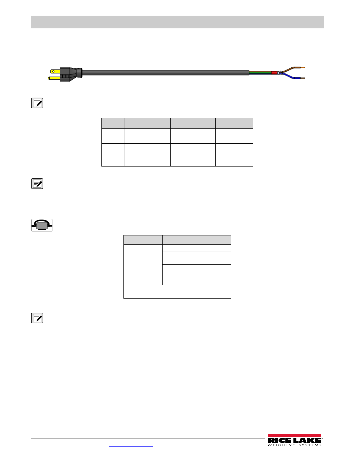
AC versions of the 680 are shipped with the AC power cable already installed.
Figure 2-10. AC Power Cable
NOTE: The AC power cable is grounded to the threaded grounding hole on the back panel of the enclosure between the
cord grip and the power supply connections rather than using Pin 3. This is a UL requirement.
Pin Description Wire Color Cable Part No.
1 120 VAC (Line In) Brown or Black 180842
2 AC Neutral Blue or White
3 Ground N/C or Green/Yellow –
4 DC Out (-V) Black 199514
5 DC Out (+V) Red
Table 2-6. AC Power Supply Pin Assignments
NOTE: Colors may vary depending on manufacturer of AC power cable. Utilize testing procedures to ensure proper
installation.
2.5.7 Load Cell Cables
To attach the cable from a load cell or junction box, route cable to the J1 connector (
cable is included in the parts kit. See
A ferrite from the parts kit must be applied to the load cell cable within 1'' (25 mm) of the load cell. The cable must be
sent through the ferrite twice.
NOTE: The Sense parameter is set to 4-wire by default and must be configured to match the load cell cable to function
properly.
For a 4-wire installation leave pins 3 and 4 empty on the connector.
For a 6-wire installation set the SENSE parameter to 6-WIRE in the CONFIG menu (Section 4.4.1 on page 34).
Table 2-7
for wiring the load cell cable from the load cell or junction box to connector.
Connector Pin Function
J1 1 +SIG
2 –SIG
3 +SENSE
4 –SENSE
5 +EXC
6 –EXC
IMPORTANT: For 4-wire connections on Rev
J2 CPU boards, short pin 3 to 5 and pin 4 to 6.
Table 2-7. J1 Pin Assignments (Load Cell)
Section 2.6 on page 18
). Connector for the
14 Visit our website www.RiceLake.com
Page 15
Installation
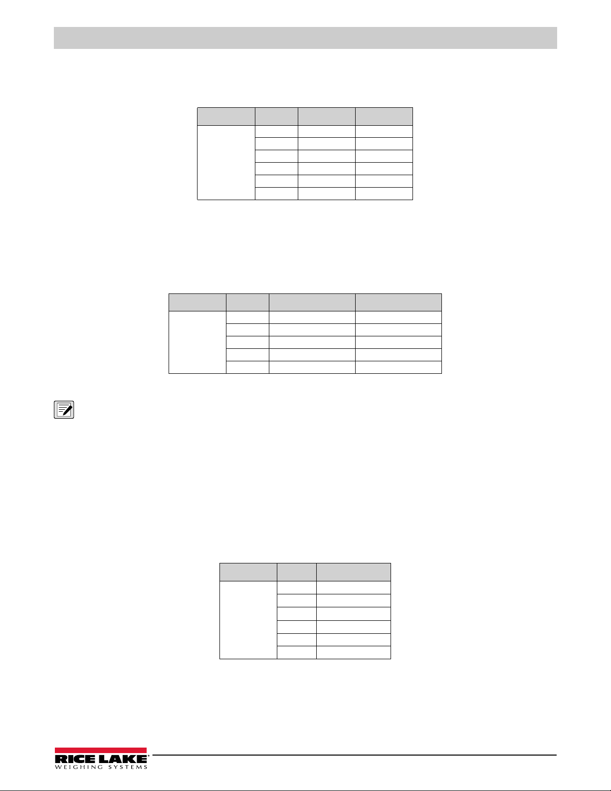
2.5.8 RS-232 Serial Communications
The J3 connector (Section 2.6 on page 18) provides a connection point for RS-232 serial communications. Two RS-232 ports
are available. See Table 2-8 for the pin assignments for the J3 connector.
Connector Pin RS232-1 RS232-2
J3 1 GND –
2 RX1 –
3 TX1 –
4 – GND
5 – RX2
6 – TX2
Table 2-8. J3 Pin Assignments (RS-232)
2.5.9 RS-485/422 Serial Communications
The J4 connector (Section 2.6 on page 18) provides a connection point for RS-485/422 serial communications. Both full duplex
(four-wire) and half duplex (two-wire) are supported through the J4 connector. See Table 2-9 for the pin assignments for the
J4 connector.
Connector Pin 4-Wire (Full Duplex) 2-Wire (Half Duplex)
J4 1 GND GND
2 A
3 B
4 Y Y
5 Z Z
Table 2-9. J4 Pin Assignments (RS-485/422)
–
–
NOTE: The DUPLEX parameter in the Serial menu (Section 4.4.4.1 on page 38) defaults to FULL and must be set to HALF for
half duplex applications.
2.5.10 Digital I/O
The Digital I/O port, J5 connector (Section 2.6 on page 18) is intended to be connected to both digital inputs and outputs.
Digital inputs can be set to provide many functions, including most keypad functions except MENU. Digital inputs are active low
(0 VDC) and inactive high (5 VDC). Use the Digital I/O menu to configure the digital inputs.
Digital outputs are used to control relays which drive other equipment. Outputs are designed to sink, rather than source current.
Each output is an open collector circuit, capable of sinking 20 mA when active. Digital outputs are active when low or at 0 VDC,
with reference to the 5 VDC supply.
Use the Digital I/O menu to set the function of the Digital I/O pins to OUTPUT and then use the Setpoints menu to configure the
digital outputs. See Table 2-10 for the pin assignments for the J5 connector.
Connector Pin Signal
J5 1 5 VDC, 250 mA max
2 GND
3 DIO1
4 DIO2
5 DIO3
6 DIO4
Table 2-10. J5 Pin Assignments (Digital I/O)
© Rice Lake Weighing Systems ● All Rights Reserved 15
Page 16
680 Synergy Plus
2.5.11 Micro USB Device Communications
The Micro USB port, J7 connector (Section 2.6 on page 18), is intended to be connected to a PC only. It appears as a Virtual
COM Port and is assigned a “COMx” designation. Applications communicate through the port like a standard RS-232
communications port.
The driver must be installed on the PC before the Micro USB device port can be used. With the PC and 680 powered on, connect
a USB cable from the PC to the micro USB connector (J7) on the 680. The PC recognizes if a device has been connected, and
attempts to install the driver needed to make it work. The driver can also be downloaded from the Rice Lake website.
NOTE: If using Windows 7 or later and the PC is connected to the Internet, the operating system may be able to install the
drivers automatically.
When the individual drivers are installed, a new COM Port designation is assigned for each physical USB port the 680 is
connected to on the PC.
For example, if the PC has two physical RS-232 COM Ports, they most likely are designated COM1 and COM2. When
connecting the 680 to a USB port on the PC, it is assigned the next available port designation, or in this case, COM3. When
plugging into the same physical USB port on the PC, the port designation is again COM3. If plugging into another physical USB
port on the PC, it is assigned the next available designation, in this case COM4.
®
After the drivers are installed, use Windows
the USB port, or open the application to be used with the 680, such as Revolution, to see which ports are available.
Configuration of the Micro USB port is done in the USBCOM sub-menu under PORTS in setup mode.
The port can be configured as either a demand port for EDP commands and printing, or as a data streaming port. Other settings
include the termination character(s), echoes, responses, the end-of-line delay and whether or not the 680 displays a 'print'
message when a print format sends data out the port.
NOTE: If a computer application has an open communications connection through the Micro USB device port and the
physical cable connection is interrupted, a soft reset must be performed on the 680 or the power must be cycled to the 680;
the connection in the computer application must be disconnected and then reconnected before it continues to
communicate with the 680.
NOTE: For the Micro USB device port, it does not matter what the settings are for Baud, Data Bits, Parity and Stop Bits in
the computer software. The port communicates in the same way regardless of these settings.
NOTE: This port is not a host port and is not intended to be connected to other devices such as keyboards, memory sticks
or printers.
Device Manager to determine the COM Port designation which was assigned to
2.5.12 Ethernet
The 680 features Ethernet TCP/IP 10Base-T/100Base-TX communication using the J8 connector (Section 2.6 on page 18),
and can support two simultaneous connections, one as a server, the other as a client.
Through an Ethernet network, software applications can communicate with the 680 using the EDP command set (Section 7.0
on page 55), or data can be streamed continuously from the 680, or printed on demand.
The Ethernet port supports both DHCP and manual configuration of settings such as the IP and netmask. In addition, the TCP
Port number, and the Default Gateway can be configured using the Ethernet sub-menu of the Ports setup menu. For more
information on configuring the Ethernet port see Section 4.4.4.3 on page 40.
Physical connection to the 680 Ethernet port can be made directly from a PC to the 680 (AdHoc Network), or through a network
router or switch. The port supports auto-sensing MDI/MDIX cable configuration, allowing either straight-through or crossover
cables to be used. See Table 2-11 for the pin assignments for the J8 connector.
Connector Pin Signal
J8 1 TX+
2 TX
3 RX+
4 RX
Table 2-11. J8 Pin Assignments (Ethernet)
NOTE: When looking into the enclosure from the backside of the indicator, pin 1 of the J8 connector is at the bottom.
-
-
16 Visit our website www.RiceLake.com
Page 17
Installation
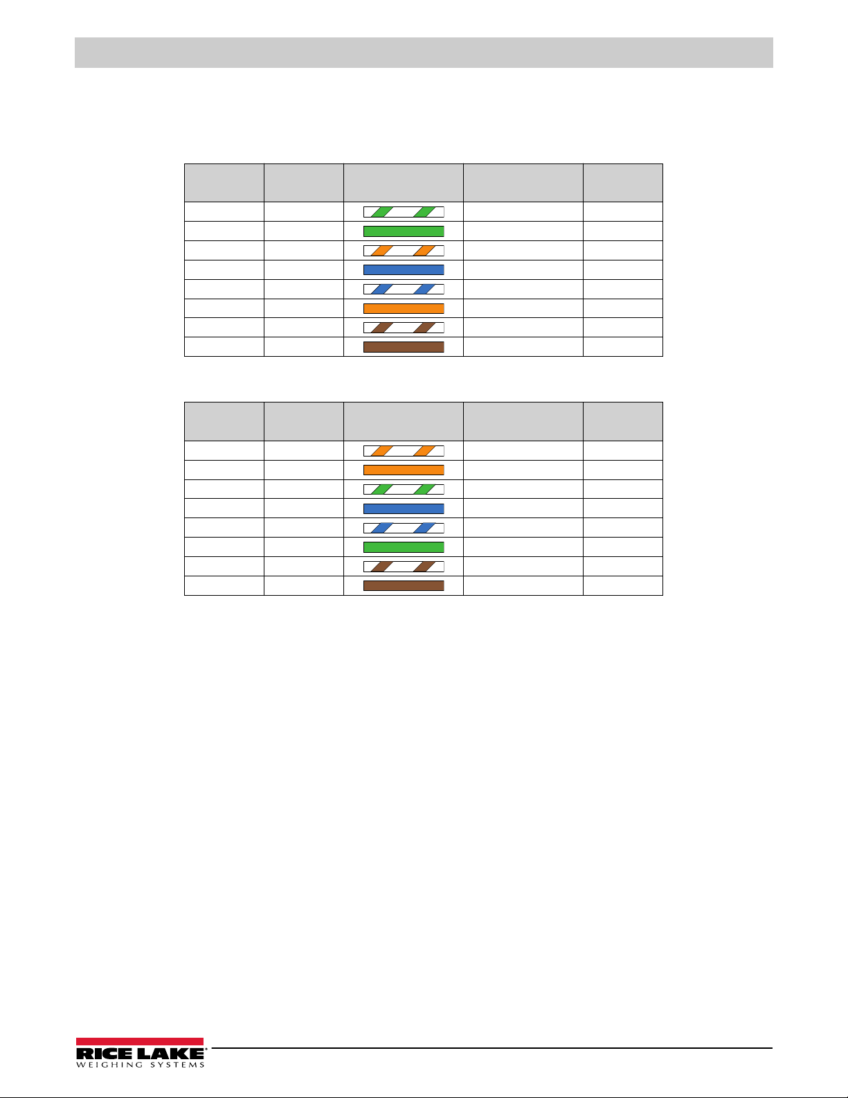
See Table 2-12 and Table 2-13 for the pin assignments when connecting a RJ45 Ethernet cable to the J8 connector. There
are two Ethernet wire standards (T568A and T568B). If the type of cable is unknown, use the wiring option in Table 2-12.
The auto-sensing feature of the Ethernet port allows either of the wiring options to work. Trim the unused wires to get them
out of the way.
RJ45 Cable
Pin
1
2
3
4
5
6
7
8
RJ45 Pin #
1
2
3
4
5
6
7
8
Wire Color
(T568A)
White/Green
Green
White/Orange
Blue
White/Blue
Orange
White/Brown
Brown
Wire Diagram
(T568A)
10Base-T Signal
100Base-TX Signal
Transmit+ 1
Transmit
Receive+ 3
Unused NA
Unused NA
Receive
Unused NA
Unused NA
Table 2-12. Ethernet Cable Pin Assignments for T568A
Wire Color
(T568B)
White/Orange
Orange
White/Green
Blue
White/Blue
Green
White/Brown
Brown
Wire Diagram
(T568B)
10Base-T Signal
100Base-TX Signal
Transmit+ 1
Transmit
Receive+ 3
Unused NA
Unused NA
Receive
Unused NA
Unused NA
Table 2-13. Ethernet Cable Pin Assignments for T568B
J8 Connector
Pin
-
-
2
4
J8 Pin #
-
-
2
4
© Rice Lake Weighing Systems ● All Rights Reserved 17
Page 18
680 Synergy Plus
J1 J3 J4 J5
J8
INSERT
SIDE UP
+
CR2032CR2032
9
LED3
LED4
LED1
LED2
HB
J25
J24
J29
RICE LAKE
Mac Address
Label
ASSY
PN/Rev
REMOTE
DISPLAY
RESET
SETUP
ON
AUDIT
OFF
SIG1+
SIG1-
SEN1+
SEN1-
EXC1+
EXC1-
GND
RX1
TX1
GND
RX2
TX2
GND
ABY
Z
RX TX
250mA
+5V
GND
DIO1
DIO2
DIO3
DIO4
TX+ TX- RX+ RX-
SDA
SCL
GND
6V
12V
POWER IN
RS-232
OPTION CARD
DIO
RS-485/422
SW1
RUN UPDATE
USB MICRO
J30
10/100Base-T
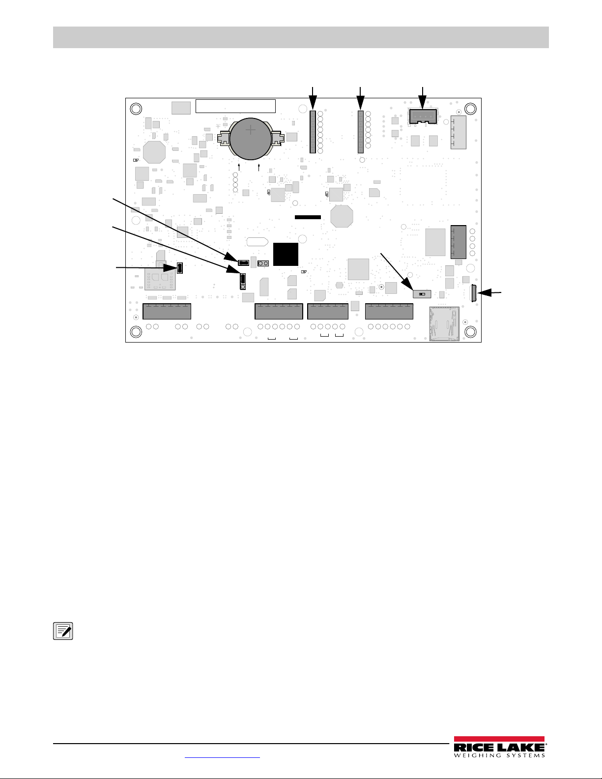
2.6 CPU Board
Setup Switch
Header (J25)
Audit Jumper
(J24)
Load Cell
Compensation
Jumper (J29)
J22 J23
Firmware Update
Switch (SW1)
J10
J7
Figure 2-11. 680 CPU Board
Connectors
• Load Cell (J1) • RS-485/422 (J4) • Micro USB (J7) • Power (J10)
• RS-232 1-2 (J3) • Digital I/O (J5) • Ethernet (J8) • Option Slot (J22/J23)
2.6.1 Option Card Port
The 680 has a single option card slot which uses the J22 and J23 connectors (Section 2.6). Instructions to install, setup or
replace an option card are provided with the option card.
2.6.2 Load Cell Compensation Jumper
The load cell compensation jumper, J29 (Section 2.6), must be set ON for load cells with balanced bridges and set to OFF for
load cells with unbalanced bridges. When OFF, the compensation jumper has the effect of lowering the excitation voltage.
Uncompensated unbalanced load cells can cause instability or calibration errors. The J29 jumper is included on boards Rev G
and newer.
Use the following procedure to determine the correct jumper position if the load cell type is unknown.
1. Disconnect load cell from indicator and use an ohmmeter to measure the following:
• +EXC to +SIG, +EXC to –SIG
• –EXC to +SIG, –EXC to –SIG
NOTE: Measured values between the excitation line and each of the signal lines should be within 2–3 Ω.
2. If the +EXC measurements are ≥ 5% larger than the –EXC measurements, set the compensation jumper in the OFF
position to compensate for the unbalanced load cell.
If the +EXC measurements are < 5% greater (or are less) than the –EXC measurements, set the jumper in the ON
position for the balanced load cell.
18 Visit our website www.RiceLake.com
Page 19
Installation
1
2
8
6
7
3
4
5
9
10
2.7 Backplate Attachment
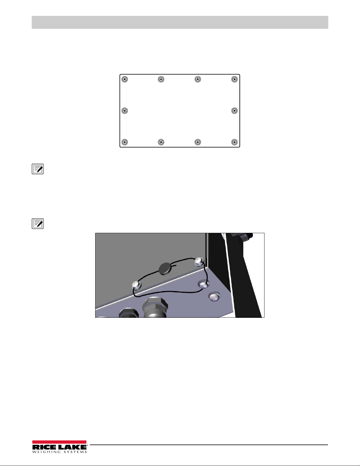
Once work inside of the enclosure is complete, reattach the backplate ground wire to the backplate. Position the backplate over
the enclosure and install the ten backplate screws. Use the torque pattern in Figure 2-12 to prevent distorting the backplate
gasket. Torque screws to 12 in-lb (1.3 N-m).
Figure 2-12. Backplate Torque Pattern
NOTE: Torqued screws may become less tight as the gasket is compressed during the torque pattern; a second torque is
required using the same pattern and torque value.
2.8 Sealing the Indicator (Optional)
Insert a lead wire seal through three fillister screws. This restricts access of the setup switch, electronics, electrical contacts and
Legal for Trade configuration parameters.
NOTE: The audit jumper (J24) must be set to off to require pressing the setup switch for access to configuration parameters.
Figure 2-13. Sealing the Indicator – No Access
1. Reposition the two fillister head backplate screws to the lower right and lower right-center screws locations.
2. Torque the two backplate screws and setup screw as specified in Section 2.5.3 on page 13.
3. Navigate the sealing wire through the fillister head screws on the backplate and the fillister head screw at the bottom of
the enclosure, as shown in Figure 2-13.
4. Seal the wire to secure.
© Rice Lake Weighing Systems ● All Rights Reserved 19
Page 20
680 Synergy Plus
2.9 Parts Kit Components
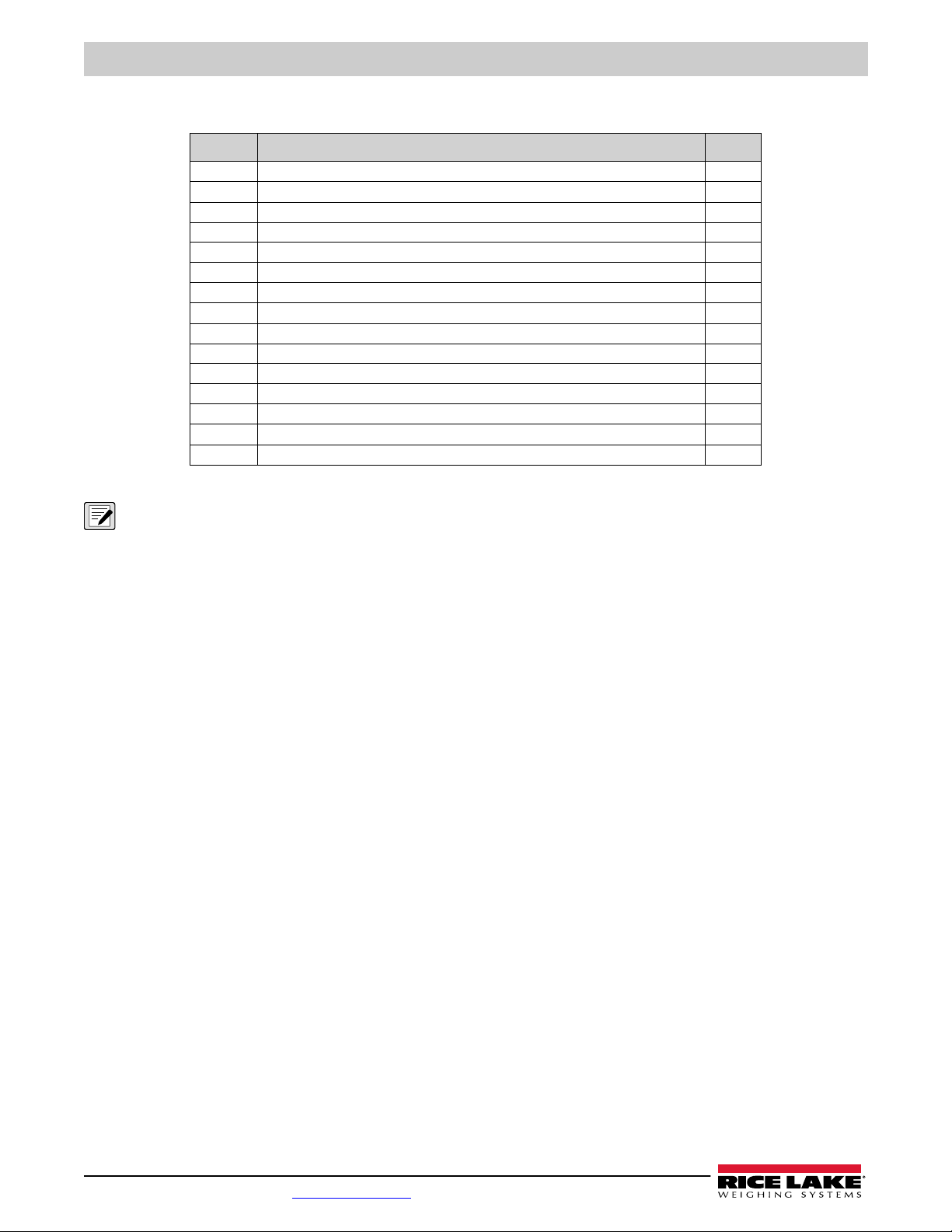
Part No. Description Qty
15631 Cable Tie, 3'' Nylon 4
15650 Mount, Cable Tie 3/4'' 2
193230 Screw, Mach M4-0.7 x 10 Phillips Pan Head SST 4
194219 Screw, Mach M4-0.7 x 10 Phillips Drilled Cheese Head SST 2
194446 Ferrite Core, Snap on Fair-rite 1
202140
19538 Post Plug, Slotted Black Plastic Stem, 1/4 x 1, Seals Inside Cord Grip 3
195993 Connector, 6 Position Screw Terminal Pluggable 3.50 mm Black 3
195995 Connector, 4 Position Screw Terminal Pluggable 3.50 mm Black 1
195998 Connector, 5 Position Screw Terminal Pluggable 3.50 mm Black 1
42149 Bumper, Rubber Grommet 0.50 (OD) x 0.281 (ID) 4
53075 Clamp, Ground Cable Shield, Radius 0.078'' 4
67550 Clamp, Ground Cable Shield, Radius 0.125'' 2
75062 Washer, Bonded Sealing #8 7/16 (0.4375) OD SST 6
94422 Label, Capacity 0.40 x 5.00 1
Screw, Mach M4-0.7 x 10 Phillips Pan Head, Zinc with External Tooth Washer SEMS
Table 2-14. AC and DC Models Parts Kit (PN 194477)
4
NOTE: The recommended cable strip length is 0.25'' (7 mm) for all 680 connectors.
20 Visit our website www.RiceLake.com
Page 21
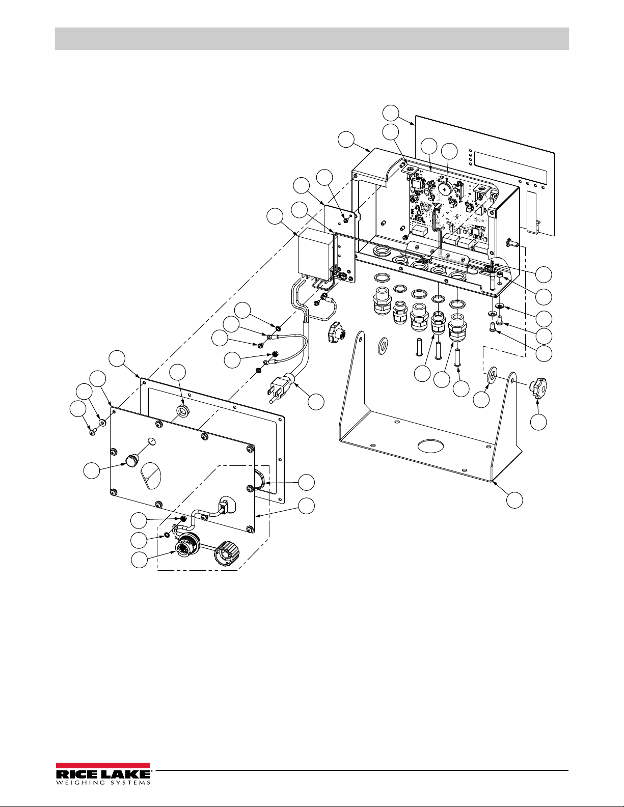
2.10 Replacement Parts
27
26
25
24
23
20
21
22
19
18
28
30
31
12
11
13
14
15
16
7
8
9
10
17
29
1
2
3
6
4
5
Backplate with RJ45 Option
Connects to J8 on CPU Board
33
32
33
34
35
680 AC Models
Installation
Figure 2-14. 680 AC Models Replacement Parts Diagram
© Rice Lake Weighing Systems ● All Rights Reserved 21
Page 22
680 Synergy Plus
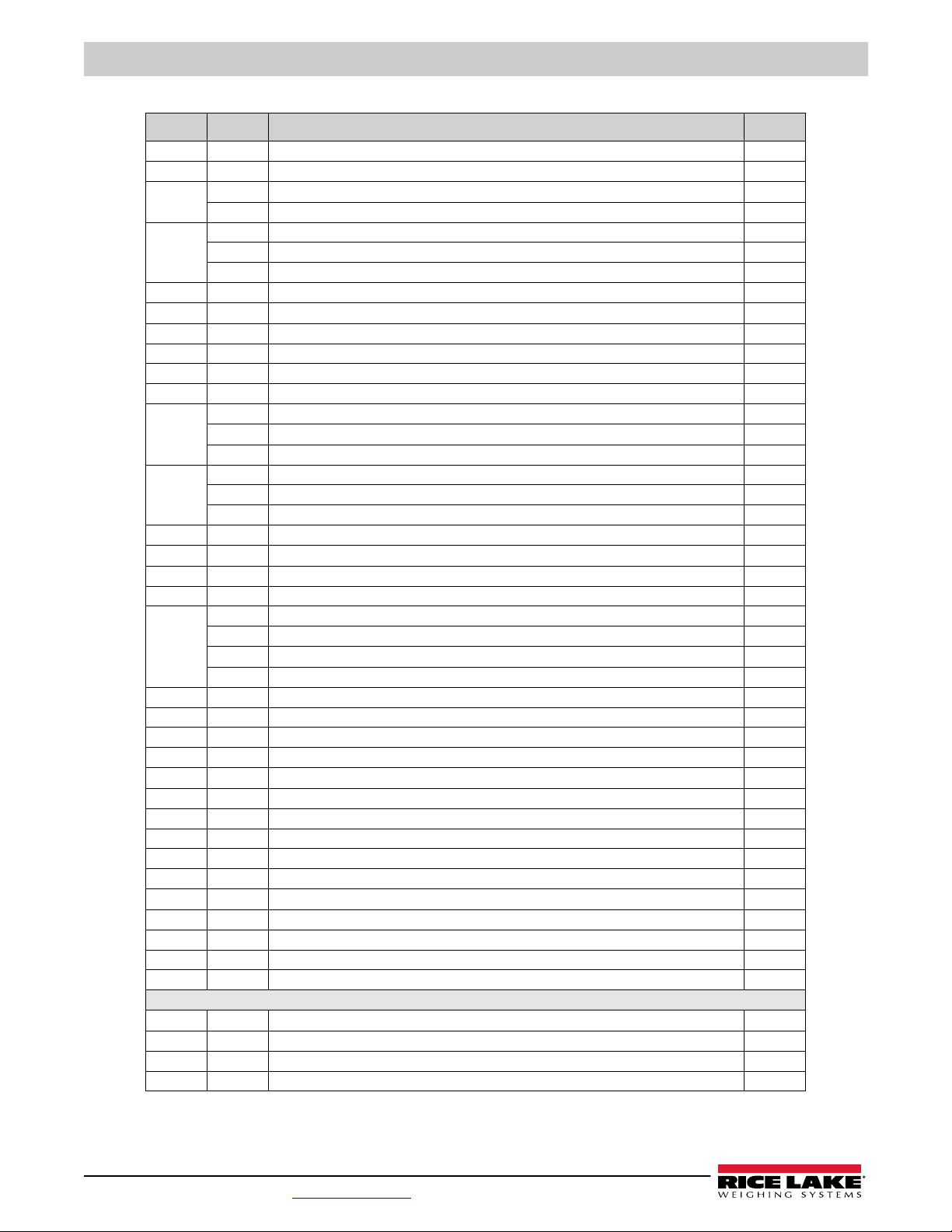
Item No. Part No. Description Qty
1 190142 Enclosure, 680 Plus Indicator Multi-Segment LED Display 1
2 190230 Overlay, 680 Plus Indicator Membrane Switch with Numeric Keys 1
3 15650 Mount, Cable Tie 3/4'' 4
4 195684 680 Replacement CPU Board with Battery 1
5 71408 Battery, CR2032 3 V Lithium Manganese Dioxide 1
6 193108 Setup Switch Assembly, Remote 1
7 187876 Nut, Lock M5 Nylon Insert A2 SST 1
8 46381 #10 Bonded Sealing Washer, 18-8 SST 2
9 150800 Screw, Mach M5-0.8 x 10 Pan Phillips SST 1
10 180861 Screw, Mach M5-0.8 x 10 mm Slotted Drilled Cheese Head SST 1
11 15626 Cord Grip, PG9 2
12 68600 Cord Grip, PG11 3
13 19538 Post, Slotted Black Seal 1/4 x 1 for Cord Grip
14 103988 Washer, Nylon 0.515-0.52 ID x 1.00 x 0.093-0.094 Thick White Nylon 6/6 2
15 180825 Knob, M6 x 1 Threaded 32 mm Diameter 7-Lobe Nylon ZN-Plated Steel 2
16 29635 Tilt Stand, SST 1
17 180842 Power Cord Assembly, NEMA 5-15 (Type B)
18 88733 Vent, Breather Sealed Gortex Membrane Black 1
19 88734 Nut, Breather Vent M12 x 1 Thread 1
20 193230 Screw, Mach M4-0.7 x 10 Phillips Pan Head SST 4
21 75062 #8 Bonded Sealing Washer, 7/16 OD SST 4
22 192562 Backplate, 680 Universal with Gore Vent Hole, No Options 1
23 84388 Gasket, Backplate 1
24 180826 Nut, KEP M4-0.7 External Tooth Lock Washer 18-8 SST 1
25 202140
26 15601 Wire, Ground 6'' with No. 8 Eye Connector 1
27 180856 Washer, M4 Internal Tooth SST 3
28 193281 Power supply, 12 V 15 W MeanWell RS-15-12 1
29 193337 Cable Assembly, 680 Power Harness, 2 Position, Flying Lead 1
30 192439 Bracket, power supply MeanWell 15 and 25 Watt 1
31 199474 Screw, Metric M3-0.5 x 5 SEMS Phillips Pan Head Zinc with External Tooth Washer 5
– 194477 680 Indicator Parts Kit (Section 2.9 on page 20) 1
32 198676 Backplate, 680 Universal with Gore Vent Hole, RJ45 Option
33 200296 RJ45 Cable Assembly, RJ45 Bulkhead to Four Position 3.50 mm Spacing Connector 1
34 180856 Washer, M4 Internal Tooth SST 1
35 180826 Nut, Kep M4 x 0.7 External Tooth Lock Washer 18-8 SST 1
15631 Cable Tie, 3'' Nylon 4
196109 Shield, ESD Lens 680, 6.25'' x 2.13'' 1
199474 Screw, Metric M3-0.5 x 5 SEMS Phillips Pan Head Zinc with External Tooth Washer 9
30375 Seal Ring, PG9 Nylon 2
15627 Lock Nut, PG9 2
68599 Seal Ring, PG11 Nylon 3
68601 Lock Nut, PG11 3
NOTE: These are provided in the Parts Kit 3
NOTE: For 193152, 195176, 200183 (AC - US) only 1
180850 Power Cord Assembly, Europe CEE7/7 (Type E)
196900 Power Cord Assembly, UK Plug BS1363 (Type G)
196901 Power Cord Assembly, AS 3112 Plug (Type I)
NOTE: For 193153, 195177, 200184 (AC - EURO) only 1
NOTE: For 196326, 196539, 200185 (AC - UK) only 1
NOTE: For 196327, 196538, 200186 (AC - AUS) only 1
Screw, Mach M4-0.7 x 10 Phillips Pan Head, Zinc with External Tooth Washer SEMS
Replacement Parts Specific to 680 Indicator with RJ45 Option
NOTE: Replaces 192562 in RJ45 option 1
Table 2-15. 680 AC Models Replacement Parts
2
22 Visit our website www.RiceLake.com
Page 23
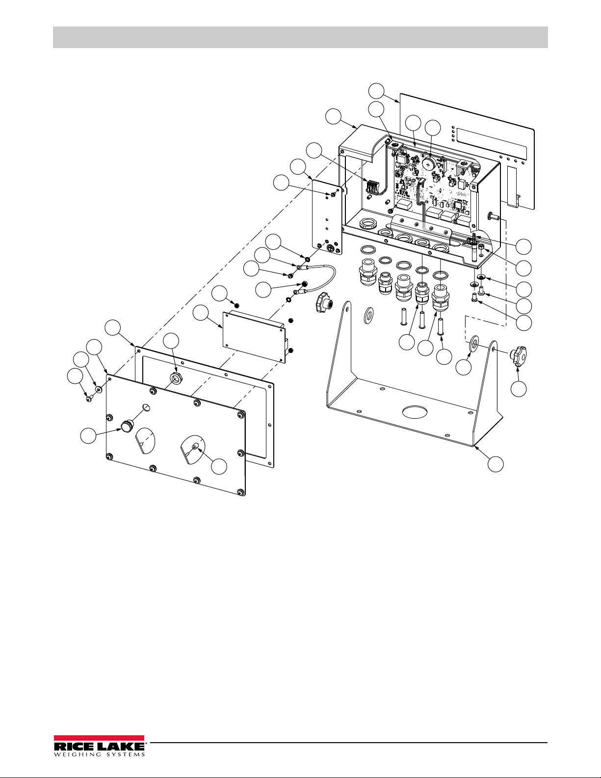
680 DC Models
27
26
25
24
23
20
21
22
19
18
28
31
32
12
11
13
14
15
16
7
8
9
10
17
30
1
2
3
6
4
5
29
Installation
Figure 2-15. 680 DC Models Replacement Parts Diagram
© Rice Lake Weighing Systems ● All Rights Reserved 23
Page 24
680 Synergy Plus
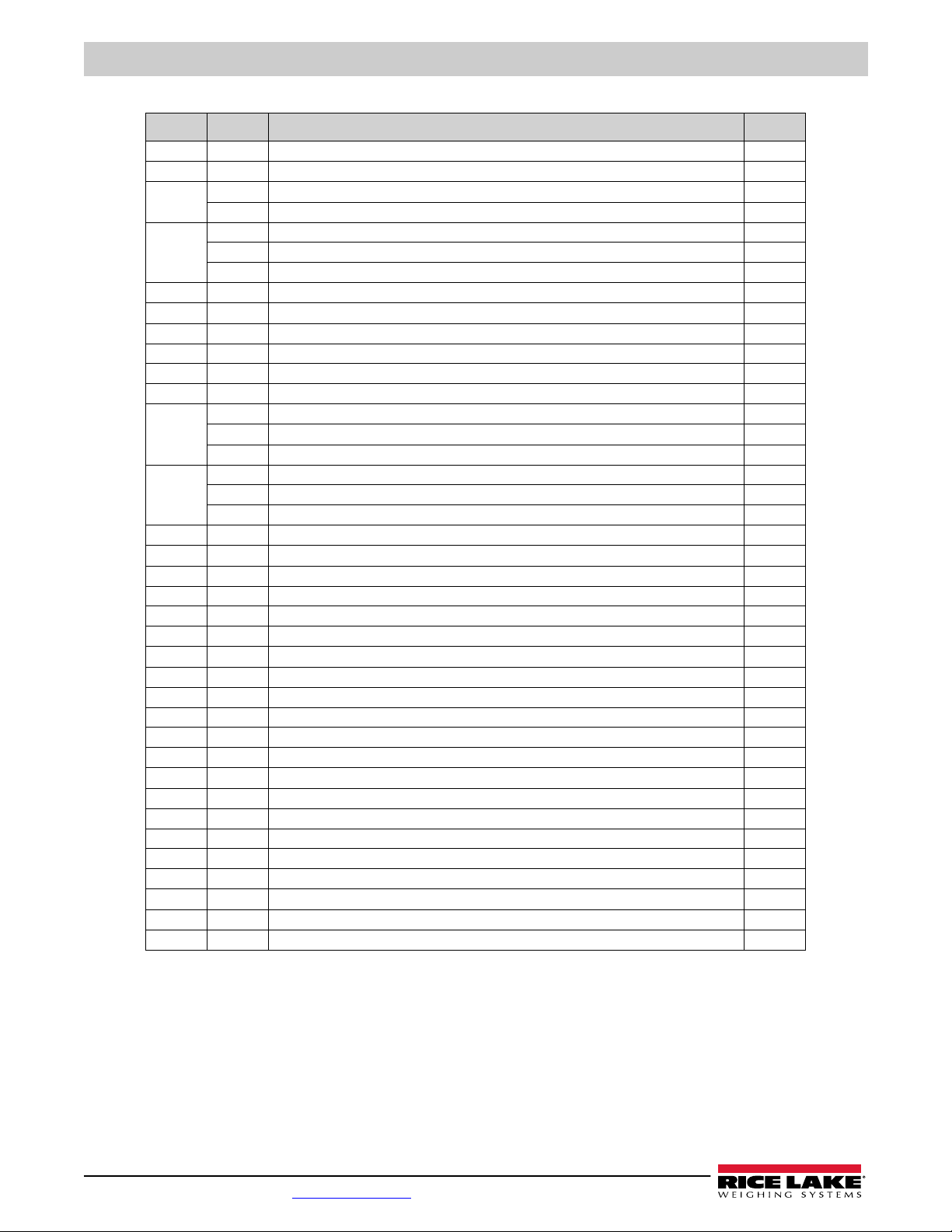
Item No. Part No. Description Qty
1 190142 Enclosure, 680 Plus Indicator Multi-Segment LED Display 1
2 190230 Overlay, 680 Plus Indicator Membrane Switch with Numeric Keys 1
3 15650 Mount, Cable Tie 3/4'' 2
4 195684 680 Replacement CPU Board with Battery 1
5 71408 Battery, CR2032 3 V Lithium Manganese Dioxide 1
6 193108 Setup Switch Assembly, Remote 1
7 187876 Nut, Lock M5 Nylon Insert A2 SST 1
8 46381 #10 Bonded Sealing Washer, 18-8 SST 2
9 150800 Screw, Mach M5-0.8 x 10 Pan Phillips SST 1
10 180861 Screw, Mach M5 x 0.8 x 10 mm Slotted Drilled Cheese Head SST 1
11 15626 Cord Grip, PG9 2
12 68600 Cord Grip, PG11 3
13 19538 Post, Slotted Black Seal 1/4 x 1 for Cord Grip
14 103988 Washer, Nylon 0.515-0.52 ID x 1.00 x 0.093-0.094 Thick White Nylon 6/6 2
15 180825 Knob, M6 x 1 Threaded 32 mm Diameter 7-Lobe Nylon ZN-Plated Steel 2
16 29635 Tilt Stand, SST 1
17 202064 Spacer, Round Nylon M3 x Ø 0.250 x 0.260 4
18 88733 Vent, Breather Sealed Gortex Membrane Black 1
19 88734 Nut, Breather Vent M12 x 1 Thread 1
20 193230 Screw, Mach M4 x 0.7 x 10 Phillips Pan Head SST 4
21 75062 #8 Bonded Sealing Washer, 7/16 OD SST 4
22 211928 Backplate, Universal DC with Gore Vent, MeanWell Supply 1
23 84388 Gasket, Backplate 1
24 180826 Nut, KEP M4 x 0.7 External Tooth Lock Washer 18-8 SST 1
25 202140
26 15601 Wire, Ground 6'' with No. 8 Eye Connector 1
27 180856 Washer, M4 Internal Tooth SST 3
28 209417 Power supply, DC/DC +12 V 30 Watt 9-36 VDC Input 1
29 202061 Nut, M3 x 0.5 Hex KEP SST 4
30 202023 Cable Assembly, 680 Power Harness, 2 Position, MTA for DC Supply 1
31 192439 Bracket, power supply MeanWell 15 and 25 Watt 1
32 199474 Screw, Metric M3 x 0.5 x 5 SEMS Phillips Pan Head Zinc with External Tooth Washer 3
– 194477 680 DC Indicator Parts Kit (Section 2.9 on page 20) 1
15631 Cable Tie, 3'' Nylon 2
196109 Shield, ESD Lens 680, 6.25'' x 2.13'' 1
199474 Screw, Metric M3 x 0.5 x 5 SEMS Phillips Pan Head Zinc with External Tooth Washer 9
30375 Seal Ring, PG9 Nylon 2
15627 Lock Nut, PG9 2
68599 Seal Ring, PG11 Nylon 3
68601 Lock Nut, PG11 3
NOTE: These are provided in the Parts Kit 3
Screw, Mach M4-0.7 x 10 Phillips Pan Head, Zinc with External Tooth Washer SEMS
Table 2-16. 680 DC Models Replacement Parts
2
24 Visit our website www.RiceLake.com
Page 25
Operation
3.0 Operation
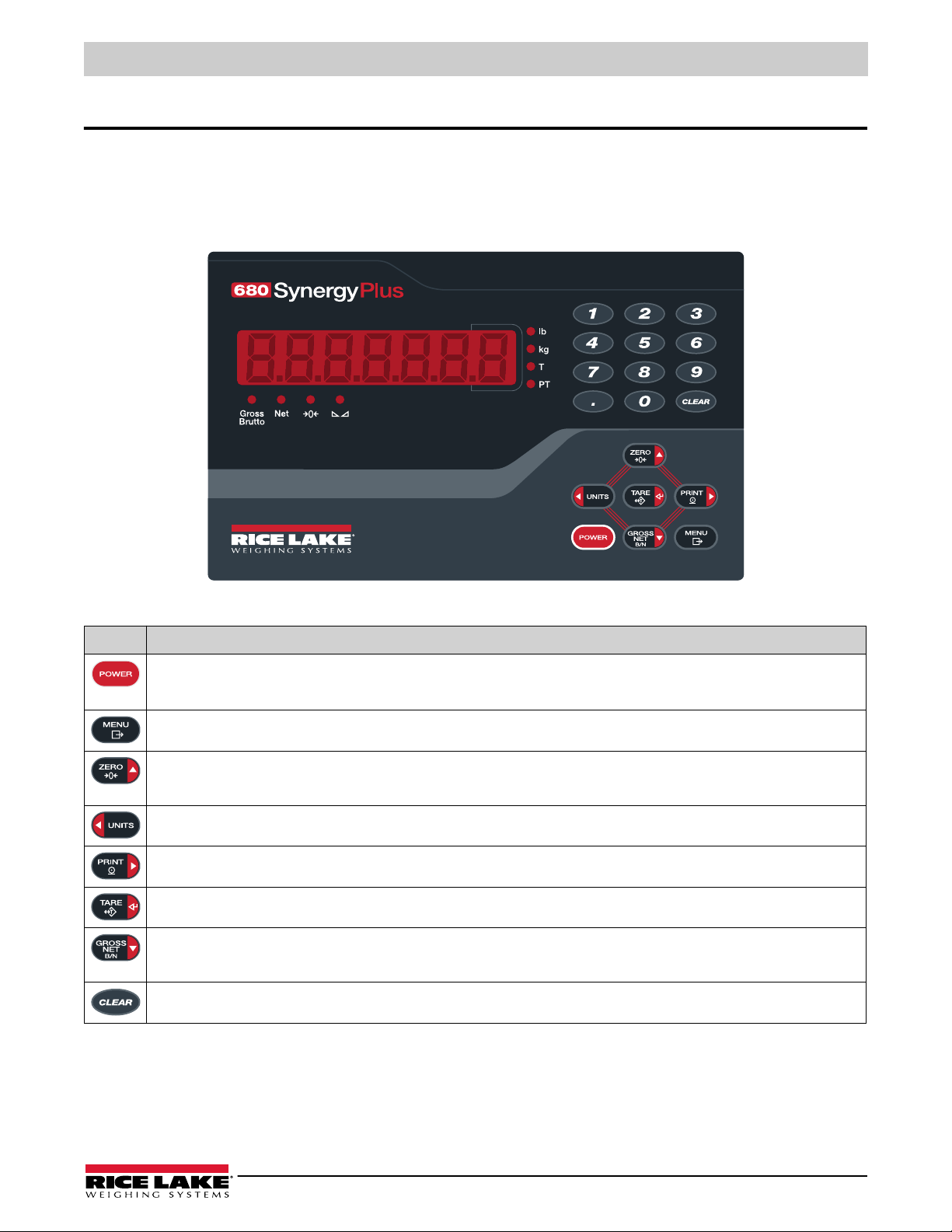
The front panel consists of a seven-segment display with seven 0.8'' (20 mm) tall digits. A negative number displays as six
digits plus the negative symbol. Front panel also includes 19 flat membrane panel, tactile feel buttons, which include six primary
scale function buttons, a numeric keypad and a power button. There are eight LED annunciators for units and scale functions.
3.1 Front Panel
Figure 3-1. 680 Front Panel
Key Function
Turns the unit ON/OFF:
If ON, press and hold for eight seconds to turn unit OFF
If OFF, press and hold for two seconds to turn unit ON
The Menu key is used to access user mode; See Section 4.1 on page 32 for more information on setting up the Menu key to access setup
mode parameters
Sets the current gross weight to zero, provided the amount of weight to be removed or added is within the specified zero range and the scale
is not in motion; The zero band is defaulted to 1.9% of full scale, but can be configured for up to 100% of full scale; Also used as the up key to
navigate menus
Switches the weight display to an alternate unit; The alternate unit is defined in the Configuration menu, and could be kg, g, lb, oz, tn or t;
Also used as the left key to navigate menus or to toggle to another digit when editing a value
Sends on-demand print format out the configured port, provided the conditions for standstill are met; RS232-1 is the default print port;
Also used as the right key to navigate menus or to toggle to another digit when editing a value
Performs one of several predetermined Tare functions dependent on the mode of operation selected in the TARE FN parameter; Also acts as
an enter key for numeric or parameter entry
Switches the display mode from gross to net, or from net to gross; If a tare value has been entered or acquired, the net value is the gross
weight minus the tare; Gross mode is represented by the Gross/Brutto annunciator; net mode is represented by the Net annunciator; Also
used as the down key to navigate menus
Clears current value in a numeric entry or clears the currently selected digit in an alphanumeric entry
Table 3-1. Buttons and Descriptions
© Rice Lake Weighing Systems ● All Rights Reserved 25
Page 26
680 Synergy Plus
3.2 LED Annunciators
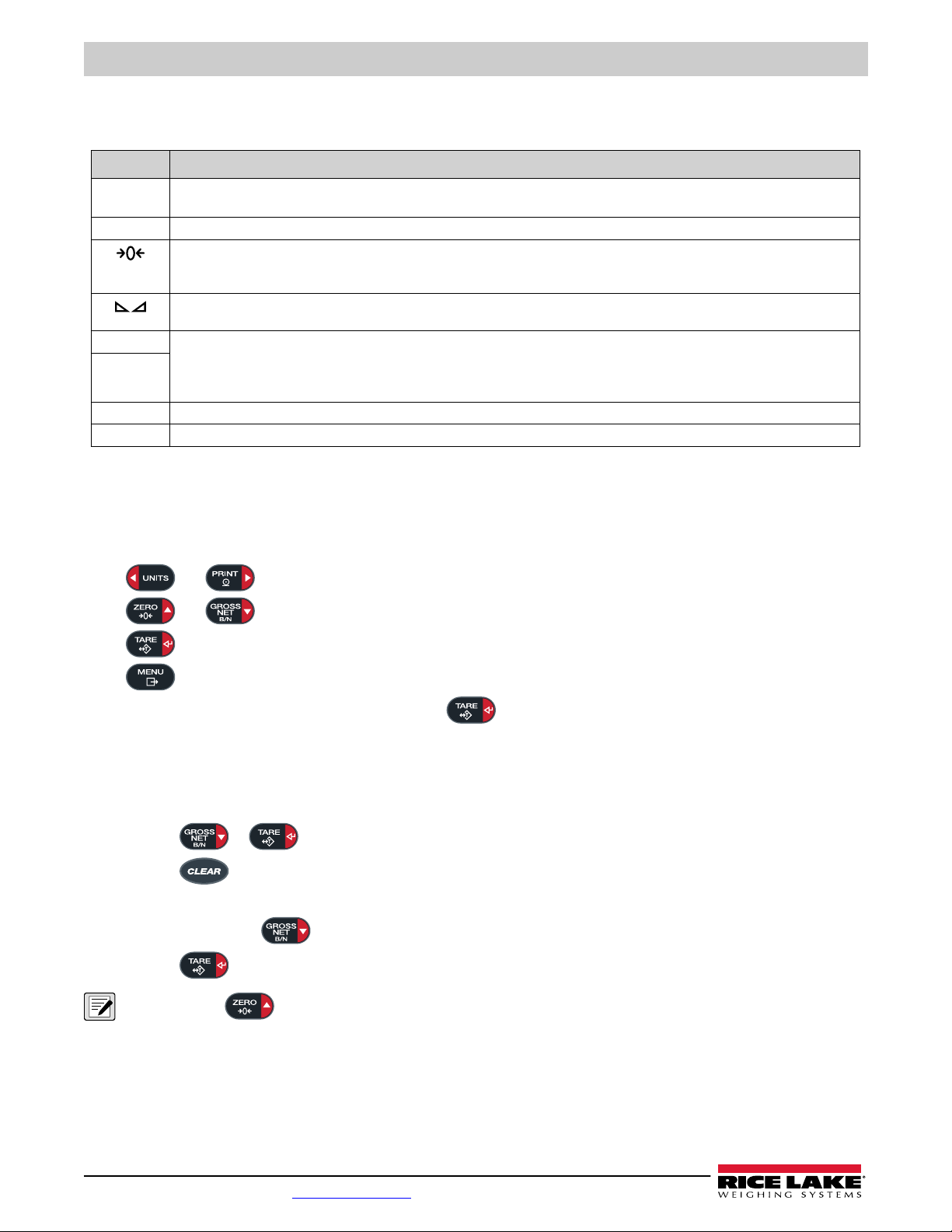
The 680 display uses a set of eight LED annunciators to provide additional information about the value being displayed.
LED Description
Gross
Brutto
Net
lb
kg
T
PT
Gross/Brutto LED – Gross weight display mode (or Brutto in OIML mode)
Net LED – Net weight display mode
The Center of Zero LED – Indicates the current gross weight reading is within ± 0.25 display divisions of the acquired zero, or is within
the center of zero band; A display division is the resolution of the displayed weight value, or the smallest incremental increase or
decrease which can be displayed or printed
Standstill LED – Scale is at standstill or within the specified motion band; Some operations, including zero, tare and print, can only be
done when the standstill LED is on
lb and kg LEDs – Indicate if pounds (lb annunciator) or kilograms (kg annunciator) are displayed; if pounds (lb) is a configured unit and
is not being displayed, then the kg annunciator lights for the displayed value; if kilograms (kg) is a configured unit and is not being
displayed, then the lb annunciator lights for the displayed value; if neither pounds (lb) or kilograms (kg) is a configured unit, then the lb
annunciator lights for the configured primary unit and the kg annunciator lights for the configured secondary unit
Tare LED – Indicates a push-button tare weight has been acquired and stored in memory
Preset Tare LED – Indicates a preset tare weight has been keyed in or entered and stored in memory
Table 3-2. LED Annunciators
3.3 General Navigation
The front panel scale function buttons are also used to navigate through the menu structure.
•
•
• enters a menu or parameter and selects/saves parameter settings or values
• to access user mode, to leave a parameter without making changes, or to return to weigh mode
• Use the numeric keypad to enter a value and press to accept the value (Section 3.3.1)
3.3.1 Numeric Value Entry
Several parameters in the menu structure require the entry of a numeric value rather than the making of a selection.
Follow this procedure to enter a numeric value:
1. Press or to enter into a parameter. The current parameter value displays.
2. Press to clear the current value.
3. Use the numeric keypad to enter a new value.
4. If necessary, press to make the value negative.
5. Press to save the new value. The next parameter in the menu displays.
and move left and right (horizontally) in a menu level
and move up and down to different menu levels
NOTE: Pressing also saves the new value, but the indicator returns up to the current parameter, rather than to the
next parameter in the menu.
26 Visit our website www.RiceLake.com
Page 27
Operation
3.3.2 Alphanumeric Entry
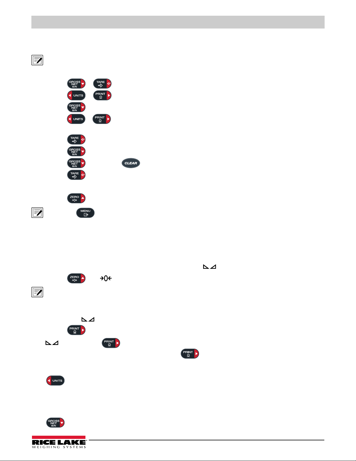
Several parameters in the menu structure require the entry of an alphanumeric value rather than the making of a selection.
NOTE: The end of the alphanumeric character string is indicated by the “_.” character symbol.
Follow this procedure to enter an alphanumeric value:
1. Press or to enter into the parameter. The current parameter entry displays.
2. Press or to move to the character to be edited.
3. Press to enter into the character options for the location at the far right of the display.
4. Press or to scroll through available character or use the numeric keypad to enter in the ASCII value of
the intended character (Section 11.9 on page 85).
5. Press to select the currently displayed character. The selected character displays in the second display field.
6. Press to enter into the character options again for the next character.
7. Press again or press to clear the current character.
8. Press to insert a space to the left of the current character.
9. Repeat the previous steps until alphanumeric entry is complete.
10. Press to save the new entry and exit the alphanumeric entry.
NOTE: Press to leave the parameter without saving the changes.
3.4 General Indicator Operation
This section summarizes basic 680 operations.
3.4.1 Zero Scale
1. In gross mode, remove all weight from the scale and wait for the LED to light.
2. Press . The LED lights to indicate the scale is zeroed.
NOTE: The scale must be stable and within the configured zero range for the scale to be zeroed. If the scale cannot be
zeroed, see Section 11.1 on page 76.
3.4.2 Print Ticket
1. Wait for the LED to be lit.
2. Press to send data to the configured port. The default print port is RS232-1 (Section 2.5.8 on page 15).
If the LED is not lit and is pressed, the print action only occurs if the scale comes out of motion within three
seconds. If the scale stays in motion for over three seconds, the press is ignored.
3.4.3 Toggle Units
Press to toggle between primary and secondary units. The current unit LED is lit.
3.4.4 Toggle Gross/Net Mode
Net mode is available when a tare value has been entered or acquired (Net = Gross minus Tare). If tare has not been entered
or acquired, the display remains in gross mode. The LED above Gross or Net indicate the current mode.
Press to toggle the display mode between gross and net.
© Rice Lake Weighing Systems ● All Rights Reserved 27
Page 28
680 Synergy Plus
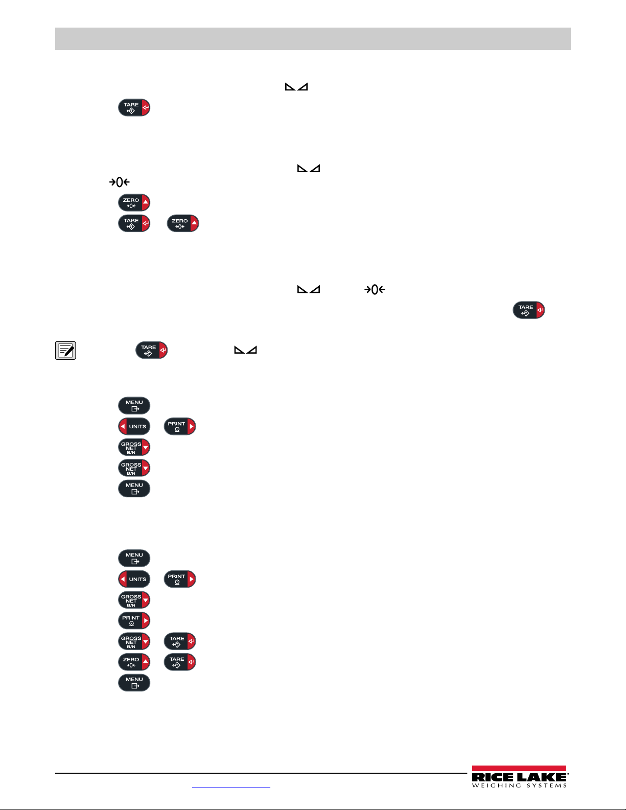
3.4.5 Acquire Tare
1. Place a container on the scale and wait for the LED to light.
2. Press to acquire the tare weight of the container. The net weight displays and the Net LED and T LED light,
confirming the tare value was entered.
3.4.6 Remove Stored Tare Value
1. Remove all weight from the scale and wait for the LED to light. The display reads the negative tare value and
the LED is lit.
2. Press to zero the scale, if needed.
3. Press (or in OIML mode). Display changes to gross weight and the Gross LED lights.
3.4.7 Preset Tare (Keyed Tare)
Tare mode must be set to keyed or both for the preset tare feature to function.
1. Remove all weight from the scale and wait for the LED and LED to light.
2. With the scale displaying zero weight, use the numeric keypad to enter the tare weight value and press .
3. The display changes to net weight and the Net LED and PT LED light, confirming the preset tare was entered.
NOTE: Press again while the LED is lit, or enter a keyed tare of zero to remove the preset tare value.
3.4.8 Display a Stored Tare
1. Press . audit displays.
2. Press or until
3. Press .
4. Press . The stored tare value displays.
5. Press twice to return to weigh mode.
If there is not a tare in the system, the value displayed is zero.
disptar displays.
tare displays.
3.4.9 Clear a Stored Tare
1. Press . audit displays.
2. Press or until
3. Press .
4. Press .
5. Press or to clear the stored tare value.
disptar displays.
clrtare displays.
tare displays.
ok displays.
6. Press or to return the audit menu.
7. Press to return to weigh mode.
28 Visit our website www.RiceLake.com
Page 29
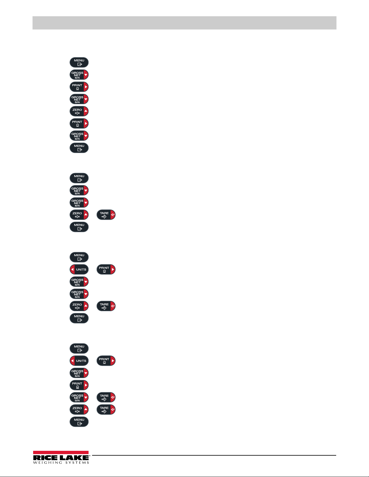
3.4.10 View Audit Trail Counters
The audit trail calibration and configuration counters can be viewed in user mode.
Operation
1. Press .
2. Press .
3. Press .
4. Press . The audit trail calibration counter displays.
5. Press .
6. Press .
7. Press . The audit trail configuration counter displays.
8. Press twice to return to weigh mode.
audit displays.
lrv displays.
calibr displays.
calibr displays.
config displays.
3.4.11 View Legally Relevant Version
1. Press . audit displays.
2. Press .
3. Press . The legally relevant version displays.
4. Press or to return the audit menu parameters.
5. Press twice to return to weigh mode.
lrv displays.
3.4.12 Display Accumulator
1. Press . audit displays.
2. Press or until
3. Press .
4. Press . The accumulator value displays.
5. Press or to return the accumulator menu parameters.
6. Press to return to weigh mode.
dispacm displays.
accum displays.
3.4.13 Print Accumulator
1. Press . audit displays.
2. Press or until
3. Press .
4. Press .
5. Press or to print the accumulator value.
6. Press or to return the accumulator menu parameters.
dispacm displays.
prtacum displays.
accum displays.
ok displays.
7. Press to return to weigh mode.
© Rice Lake Weighing Systems ● All Rights Reserved 29
Page 30
680 Synergy Plus
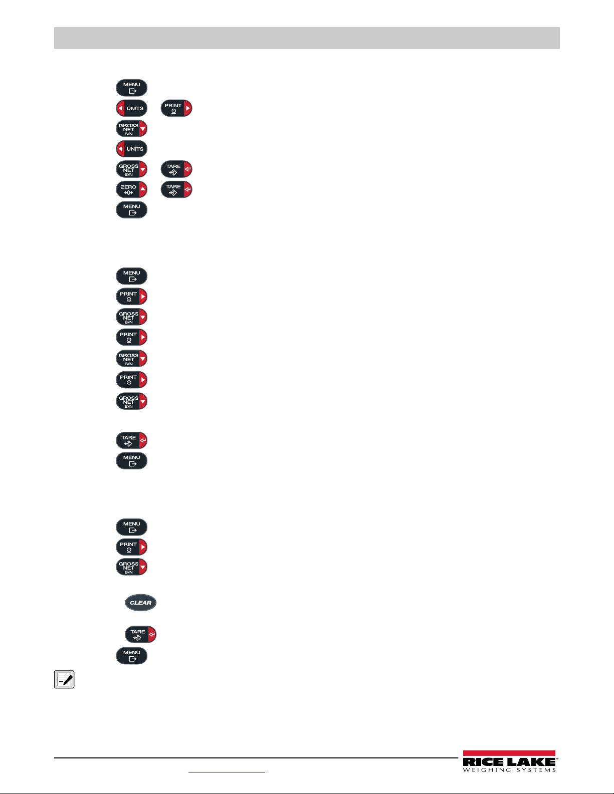
3.4.14 Clear Accumulator
1. Press . audit displays.
2. Press or until
3. Press .
4. Press .
5. Press or to clear the accumulator value.
6. Press or to return the accumulator menu parameters.
7. Press to return to weigh mode.
dispacm displays.
clracum displays.
accum displays.
ok displays.
3.4.15 Enter New Unit ID
Entering a new Unit ID requires access to setup mode (Section 4.1 on page 32).
1. Press .
2. Press .
3. Press .
4. Press to scroll until
5. Press .
6. Press to scroll until
audit displays.
setup displays.
config displays.
progrm displays.
pwrupm displays.
uid displays.
7. Press . The current unit ID value displays.
8. Edit the value using the keypad (Section 3.3.1 on page 26).
9. Press when the value is correct.
10. Press to return to weigh mode.
3.4.16 View and Edit Time Value
To view and edit the current time:
1. Press .
2. Press multiple times until
3. Press to view the current set time.
4. To edit the time value use the following method:
• Press to clear the current time
• Use the numeric keypad to enter the new time value
• Press to accept the new time value once correct
5. Press to return to weigh mode.
NOTE: Time is backed up by the internal battery and is not lost if the main power is interrupted.
See Section 4.4.5 on page 41 for time formatting options.
audit displays.
time displays.
30 Visit our website www.RiceLake.com
Page 31

3.4.17 View and Edit Date Value
To view and edit the current date:
Operation
1. Press .
2. Press multiple times until
3. Press to view the current set date.
4. To edit the date value use the following method:
• Press to clear the current date
• Use the numeric keypad to enter the new date value and press to accept the desired value
5. Press to return to weigh mode.
NOTE: Date is backed up by the internal battery and is not lost if the main power is interrupted.
See Section 4.4.5 on page 41 for date formatting options.
audit displays.
date displays.
3.4.18 View Configured Setpoint Values
See Section 9.0 on page 67 more information.
1. Press .
2. Press twice.
3. Press . The lowest configured setpoint number displays.
4. Press to navigate to the desired setpoint number (1-8).
NOTE: Only configured setpoint numbers display. Displayed setpoints are read only unless access is set to on.
See Section 4.4.8 on page 46 for the complete setpoint menu.
audit displays.
Setpnt displays.
5. Press . value displays.
6. Press again to view the current configured setpoint value.
7. To edit the setpoint value use the following method:
• Press to clear the current value
• Use the numeric keypad to enter the new value and press to accept it
• Press to accept the new value once correct
8. Press to return to weigh mode.
3.4.19 Reset Configuration
1. Access setup mode by pressing the setup switch (Figure 4-1 on page 32). Config displays.
2. Press .
3. Press .
4. Press .
5. Press or to reset the configuration setting.
6. Press or .
7. Press to return to weigh mode.
dfltcfg displays.
no displays.
yes displays.
ok displays.
no displays again.
© Rice Lake Weighing Systems ● All Rights Reserved 31
Page 32
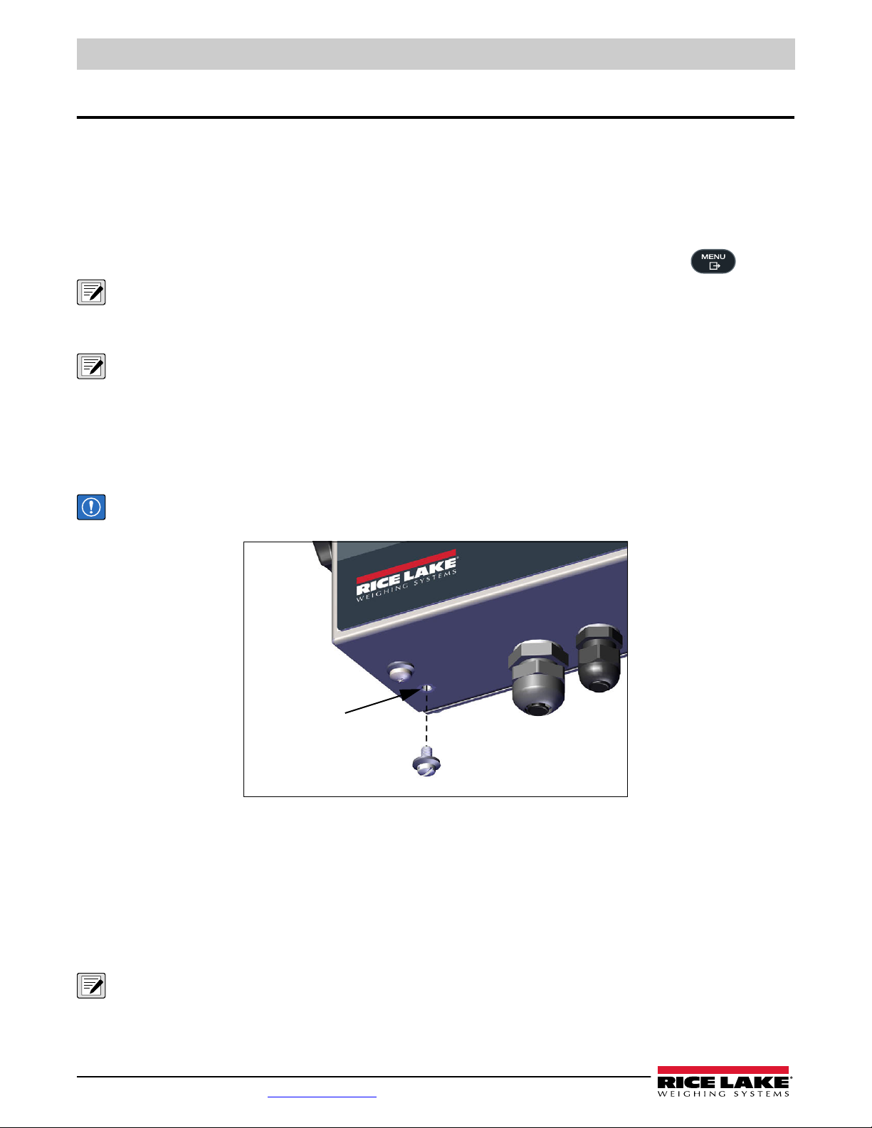
680 Synergy Plus
4.0 Configuration
There are two types of configuration parameters in the 680, setup mode parameters (or Legal for Trade configuration) and user
mode parameters (or non-legal configuration). Setup mode parameters are accessed by pressing the setup switch
User mode parameters are accessed by pressing the menu button and do not require pressing the setup switch.
The following sections provide graphic representations of the 680 menu structures. Most menu diagrams are accompanied by a
table which describes all parameters and parameter values associated with the menu. The factory default setting appears at the
top of each column in bold type.
The audit, setpoints, accumulator, tare, time, date, Mac ID and version menus can be accessed by pressing .
NOTE: The top-level setpoints menu displays the setpoint value of configured setpoints and is accessible with the menu
button. Complete configuration of setpoints is under the setup menu and requires the setup switch for access.
The setup menu are accessed by pressing the setup switch (Section 4.1).
NOTE: All weight related parameters must be configured prior to calibrating the unit.
4.1 Setup Switch
In order to configure the 680, it must be placed in setup mode with the setup switch. The setup switch is accessed through a
small hole on the bottom of the enclosure. Remove the setup switch screw and insert a non-conductive tool into the access hole
to press the setup switch.
IMPORTANT: Use caution when inserting the non-conductive tool into the enclosure. Insert the tool about 3/4'' (19 mm),
until the switch is engaged. Do not use excessive force which could damage the switch.
(Section 4.1).
Setup Switch
Access
Figure 4-1. Setup Switch Access
When the 680 is placed in setup mode, the setup menu is accessed and config displays. See Section 4.4 on page 34 for a
detailed breakdown of this menu. Torque the setup switch screw to 10 in-lb (1.1 N-m) when reinserting.
Audit Jumper
The audit jumper (J24) turns setup mode access on and off. Access to setup mode is allowed without pressing the setup switch
when the audit jumper is in the on position. Access to setup mode requires pressing the setup switch when the audit jumper is in
the off position. See
NOTE: In certain Legal for Trade applications it is necessary to seal the indicator to restrict access to the setup switch
(Section 2.8 on page 19). Breaking of the seal terminates the Legal for Trade status of the indicator.
32 Visit our website www.RiceLake.com
Section 2.6 on page 18
for the location of the audit jumper on the CPU board.
Page 33
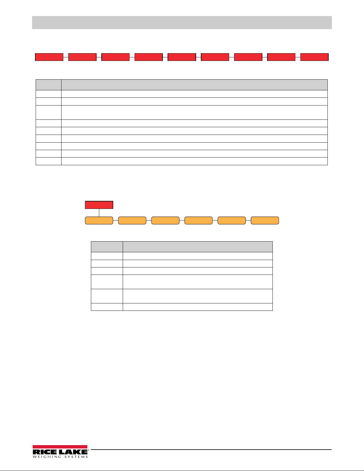
4.2 Main Menu
Audit Setup Setpnt Accum Tare time date mac id Vers
Audit
LRV Calibr Config dest 1 dest 2 dmpaud
Figure 4-2. Main Menu
Menu Description
Audit Audit – Displays the legally relevant firmware version and allows access to view/print audit trail information; See Section 4.3
Setup Setup – Set configuration parameters for indicator (only accessible in setup mode); See Section 4.4 on page 34
Setpnt Setpoints – Displays the setpoint value of configured setpoints; Read only unless access parameter for the setpoint is set to ON;
Setpoints are fully configurable in the setup menu while the indicator is in setup mode
Accum Accumulator – Displays, prints and clears accumulated weight value; See Section 4.5 on page 50
Tare Tare – Displays and clears stored tare value; See Section 4.6 on page 50
time Time – Displays the time and allows the time to be edited (24-hour)
date Date – Displays the date and allows the date to be edited
mac id Mac ID – Displays the Mac ID of the Ethernet Communications Interface (read only)
Vers Version – Displays the installed firmware version number
Table 4-1. Main Menu Descriptions
4.3 Audit Menu
Configuration
Figure 4-3. Audit Menu
Parameter Description
Lrv LRV – Legally relevant firmware version
Calibr Calibration – Displays total number of calibration events (read only)
Config Configuration – Displays total number of configuration events (read only)
dest 1 Destination Port 1 – Audit trail port; Settings: RS232-1 (default), RS232-2,
RS485, TCPC, TCPS, USB, NONE
dest 2 Destination Port 2 – Audit trail port; Settings: NONE (default), RS232-1,
RS232-2, RS485, TCPC, TCPS, USB
dumpaud Dump Audit Trail – Sends the audit parameters to the configured print port
Table 4-2. Audit Menu Descriptions
© Rice Lake Weighing Systems ● All Rights Reserved 33
Page 34
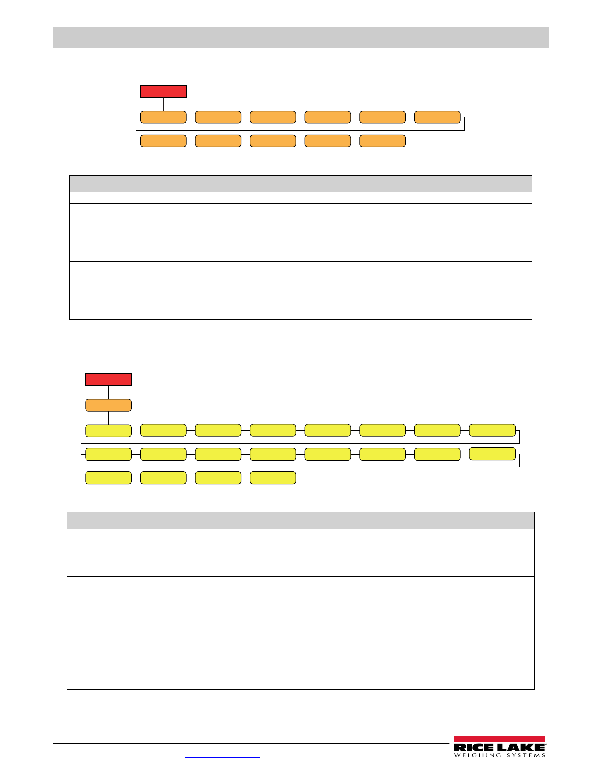
680 Synergy Plus
Setup
Config Format Calibr Comm Progrm
sFormt Setpnt DigIO AlgOut dfltcfg
pformt
Setup
Config
Capacty
fltrchn
digfl1 digfl2
digfl3
dfsens dfthrh
adsens
adthrh dampval
Ztrkbn Zrange Initzro motban ovrloa smprat
rtltrap tare fn ss time sense
4.4 Setup Menu
Figure 4-4. Setup Menu
Menu Description
Config Configuration – See Section 4.4.1 for menu structure and parameter descriptions of the Configuration menu
Format Format – See Section 4.4.2 on page 36 for menu structure and parameter descriptions of the Format menu
Calibr Calibration – See Section 4.4.3 on page 36 for menu structure and parameter descriptions of the Calibration menu
Comm Communication – See Section 4.4.4 on page 37 for menu structure and parameter descriptions of the Communication menu
Progrm Program – See Section 4.4.5 on page 41 for menu structure and parameter descriptions of the Program menu
Pformt Print Format – See Section 4.4.6 on page 44 for menu structure and parameter descriptions of the Print Format menu
sformt Stream Format – See Section 4.4.7 on page 45 for menu structure and parameter descriptions of the Stream Format menu
Setpnt Setpoints – See Section 4.4.8 on page 46 for menu structure and parameter descriptions of the Setpoint menu
Digio Digital I/O – See Section 4.4.9 on page 49 for menu structure and parameter descriptions of the Digital I/O menu
Algout Analog Output – See Section 4.4.10 on page 49 for menu structure and parameter descriptions of the Analog Output menu
dfltcfg Default Configuration – See Section 3.4.19 on page 31 for instructions to reset the configuration settings
Table 4-3. Setup Menu Descriptions
4.4.1 Configuration Menu
Figure 4-5. Setup – Configuration Menu
Menu Description
Capacty Capacity – Maximum rated capacity of the scale; Enter value: 0.0000001–9999999.0, 10000.0 (default)
Ztrkbn Zero Track Band – Automatically zeros the scale when within the range specified, as long as the input is within the zrange and
scale standstill; When weight is within the zero band, the center of zero annunciator displays; Max legal value depends on local
regulations; Specify the zero tracking band in ± display divisions; Enter value: 0.0–100.0, 0.0 (default)
Zrange Zero Range – The total amount the scale can be zeroed; Zero range represents a percentage of capacity; The default value of
1.9 represents ±1.9% around the calibrated zero point, for a total range of 3.8%; A value of 0.0 prevents zeroing; Maximum legal
value depends on local regulations; Enter value: 0.0–100.0, 1.9 (default)
Initzro Initial Zero Range – When the indicator is turned on and the weight value is between the ± percent range specified in Calibrated
Zero, the indicator automatically zeros off the weight; Enter value: 0.0–100.0, 0.0 (default)
Motban Motion Band – Sets the level, in display divisions, at which scale motion is detected; If motion is not detected for the time defined
by ss time, the standstill symbol lights; Some operations, including print, tare, and zero, require the scale to be at standstill;
Maximum legal value varies depending on local regulations; If this parameter is set to 0, the standstill annunciator is always lit
and operations requiring standstill are performed regardless of scale motion; If 0 is selected, ztrkbnd must also be set to 0;
Enter value: 0–100, 1 (default)
Table 4-4. Setup – Configuration Menu Descriptions
34 Visit our website www.RiceLake.com
Page 35
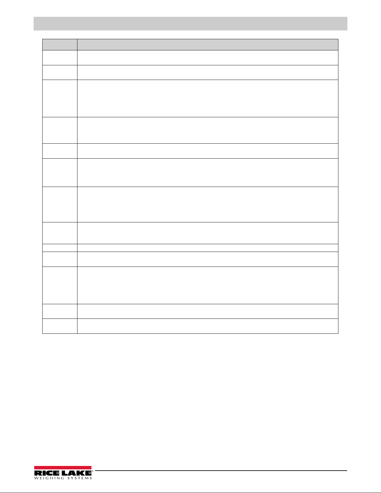
Configuration
Menu Description
Ovrloa Overload – Determines the point at which the display blanks and the overload error message displays (^^^^^^^);
Maximum legal value varies depending on local regulations; Settings: FS+2% (default), FS+1D, FS+9D, FS
Smprat
fltrchn Filter Chain Type – Sets the filter type to be used; Settings:
digfl1-3 Digital Filters – Sets the digital filtering rate used to reduce the effects of environmental influences from the immediate area of
Dfsens Digital Filter Sensitivity – Specifies the number of consecutive A/D readings which fall outside the Filter Threshold before filtering
Dfthrh Digital Filter Threshold – Sets a threshold value, in display divisions; when a number of consecutive A/D readings (Digital Filter
Adsens Adaptive Filter Sensitivity – Controls the stability and response time of the scale; Settings:
Adthrh Adaptive Filter Threshold – Sets the adaptive filter weight threshold value (in display divisions); a weight change exceeding the
Dampval Damping Value – Sets the damping time constant (in 0.1 sec intervals); Enter value: 1–2560, 10 (default)
Rtltrap RattleTrap – Enables RattleTrap filtering; Effective at eliminating vibration effects, environmental influences and mechanical
Tare fn Tare Function – Enables or disables push-button and keyed tare; Settings:
Ss time Standstill Time – Specifies the length of time the scale must be out of motion, before the scale is considered to be at standstill (in
sense Sense – Specifies the type of load cell cable connected to the J1 connector (Section 2.5.6 on page 14);
Sample Rate – Selects measurement rate, in samples per second, of the analog-to-digital converter; Lower sample rate values
provide greater signal noise immunity; Settings: 6.25HZ, 7.5HZ, 12.5HZ, 15HZ, 25HZ, 30HZ (default), 50HZ, 60HZ, 100HZ, 120HZ
AVGONLY (default) – Digital Rolling Average Filter (Section 11.7.1 on page 81); Uses DIGFL1-3, DFSENS and DFTHRH
ADPONLY – Adaptive Filter (Section 11.7.2 on page 82); Uses ADSENS and ADTHRH
DMPONLY – Damping Filter (Section 11.7.3 on page 83); Uses DAMPVAL
RAW – No filtering
the scale; Settings indicate the number of A/D conversions per update which are averaged to obtain the displayed reading; a
higher number gives a more accurate display by minimizing the effect of a few noisy readings, but slows down the response time
of the indicator; Settings: 1, 2, 4 (default), 8, 16, 32, 64, 128, 256
is suspended; Settings: 2OUT (default), 4OUT, 8OUT, 16OUT, 32OUT, 64OUT, 128OUT
Sensitivity) falls outside of this threshold value (when compared to the output of the filter), filtering is suspended and the A/D
value is sent straight through the filter; Filtering is not suspended if the threshold is set to NONE; Settings: NONE (default), 2D,
5D, 10D, 20D, 50D, 100D, 200D, 250D
LIGHT (default) – Fastest response to small weight changes, but less stable
MEDIUM – Has a quicker response time than heavy, but more stable than light
HEAVY – Results in an output which is more stable but settles slowly; small changes in weight data (a few grads) on the
scale base are not seen quickly
threshold resets the filtered values; must be set above the noise disturbances in the system (if set to zero, the filter is disabled);
Enter value: 0–2000, 10 (default)
interference from nearby machinery, may increase response time over standard digital filtering; Settings: OFF (default), ON
BOTH (default) – Both push-button and keyed tare are enabled
NOTARE – No tare allowed (gross mode only)
PBTARE – Push-button tares enabled
KEYED – Keyed tare enabled
0.1 sec intervals); Enter value: 0–600, 10 (default)
Settings: 4-WIRE (default), 6-WIRE
Table 4-4. Setup – Configuration Menu Descriptions (Continued)
© Rice Lake Weighing Systems ● All Rights Reserved 35
Page 36
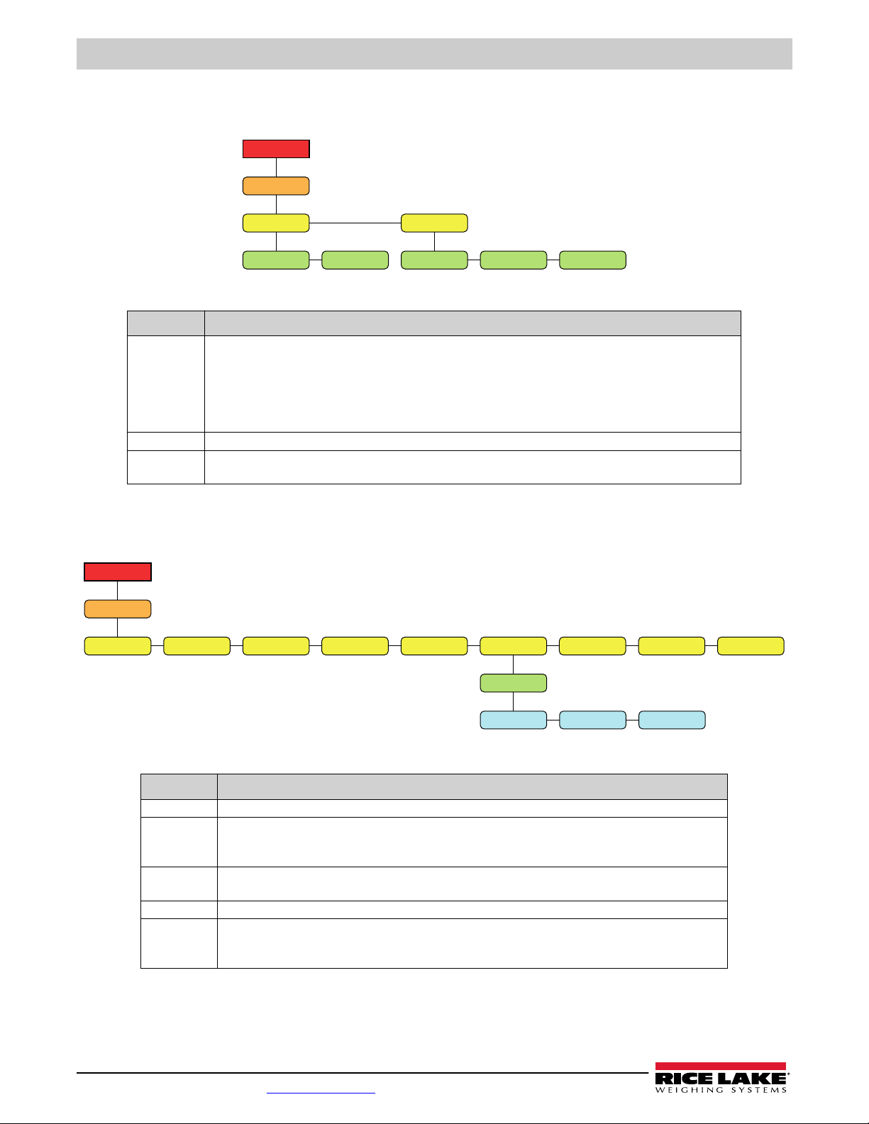
680 Synergy Plus
Setup
Format
FORMAT UNITS
PRIMAR
FORMAT UNITS ENABLED
SECNDR
Setup
Calibr
zerocntWZERO WVAL spancntWSPAN
Point 1-4
WLIN REZERO
Wlin v1-4 wlin c1-4 wlin f1-4
lstzero tmpzero
4.4.2 Format Menu
4.4.2.1 Primary and Secondary Menus
Figure 4-6. Format – Primary and Secondary Menus
Parameter Description
format Format – Sets the decimal point and the display divisions for the Primary (primar) and Secondary (secndr)
display weight format; For example, select 8888.885 if a count by of 0.005 is needed or select 8888820 if a count by
of 20 is needed (the 8s serve as placeholders and show a breakdown of how digits will display);
Settings: 8888881 (Primary default), 8888882, 8888885, 8888810, 8888820, 8888850, 8888100, 8888200,
8888500, 88.88881, 88.88882, 88.88885, 888.8881, 888.8882, 888.8885, 8888.881, 8888.882, 8888.885,
88888.81, 88888.82, 88888.85, 888888.1, 888888.2, 888888.5 (Secondary default)
Units Units – Sets the units type; Settings: LB (Primary default), KG (Secondary default), OZ, TN, T, G, NONE
Enabled Enabled – Enables the front panel UNITS button to toggle between the primary and secondary formats (only
displays under Secondary); Settings: ON (default), OFF
Table 4-5. Format – Primary and Secondary Menu Parameters
4.4.3 Calibration Menu
Figure 4-7. Setup – Calibration Menu
Parameter Description
wzero Zero Calibration – Executes the zero calibration process; See Section 5.1 on page 51
zerocnt Zero Calibration Count – Displays the raw count value at the zero weight; A zero calibration (WZERO)
generates this raw count value; Manually changing this count value changes the zero weight and negates the
zero calibration
wval Test Weight Value – Sets the weight value for the span calibration; See Section 5.1 on page 51;
Enter value: 0.000001–9999999.0, 10000.0 (default)
wspan Span Calibration – Executes the span calibration process; See Section 5.1.1 on page 51
spancnt Span Calibration Count – Displays the raw count value at the span weight; A span calibration (WSPAN)
generates this raw count value; Manually changing this count value changes the span weight and negates the
span calibration
Table 4-6. Setup – Calibration Menu Parameter
36 Visit our website www.RiceLake.com
Page 37
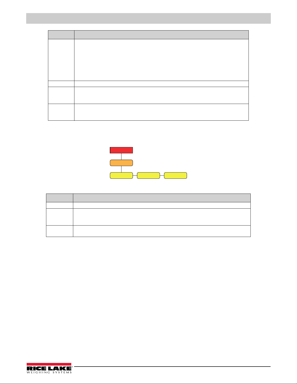
Parameter Description
Setup
Comm
SERIAL USB ETHrNET
wlin Linear Calibration – A linear or multi-point calibration is performed by entering up to four additional calibration
points; See Section 5.1.2 on page 52
WLIN V# – Sets the test weight value for linear calibration point
WLIN C# – Executes the linear calibration process for the point; generates the raw count value (F) for
the test weight value (V)
WLIN F# – Displays the raw count value at the linear point weight; A linear calibration (WLIN C#)
generates this raw count value; Manually changing this count value changes the linear point weight and
negates the linear calibration for the point
rezero Rezero – Removes an offset value from the zero and span calibrations; See Section 5.2.3 on page 52
lstzero Last Zero – Takes the last pushbutton zero in the system (from weigh mode) and uses it as the new zero
reference point, after which a new span calibration must be performed; This calibration cannot be performed
when calibrating a scale for the first time; See Section 5.2.1 on page 52
tmpzero Temporary Zero – Temporarily zeros the displayed weight of a non-empty scale, after a span calibration was
performed; The difference between the temporary zero and the previously calibrated zero value is used as an
offset; See Section 5.2.2 on page 52
4.4.4 Communication Menu
Configuration
Table 4-6. Setup – Calibration Menu Parameter (Continued)
Figure 4-8. Setup – Communication Menu
Menu Description
serial Serial Port – Supports RS-232 and RS-485/422 serial communications; See Section 4.4.4.1 on page 38
usb USB – Intended to be connected to a PC only; appears as a Virtual COM Port and is assigned a “COMx”
designation; applications communicate through the port like a standard RS-232 communications port;
See Section 4.4.4.2 on page 39
ethrnet Ethernet – Features Ethernet TCP/IP 10Base-T/100Base-TX communication and can support two simultaneous
connections, one as a server, the other as a client; See Section 4.4.4.3 on page 40
Table 4-7. Setup – Communication Menu Descriptions
© Rice Lake Weighing Systems ● All Rights Reserved 37
Page 38
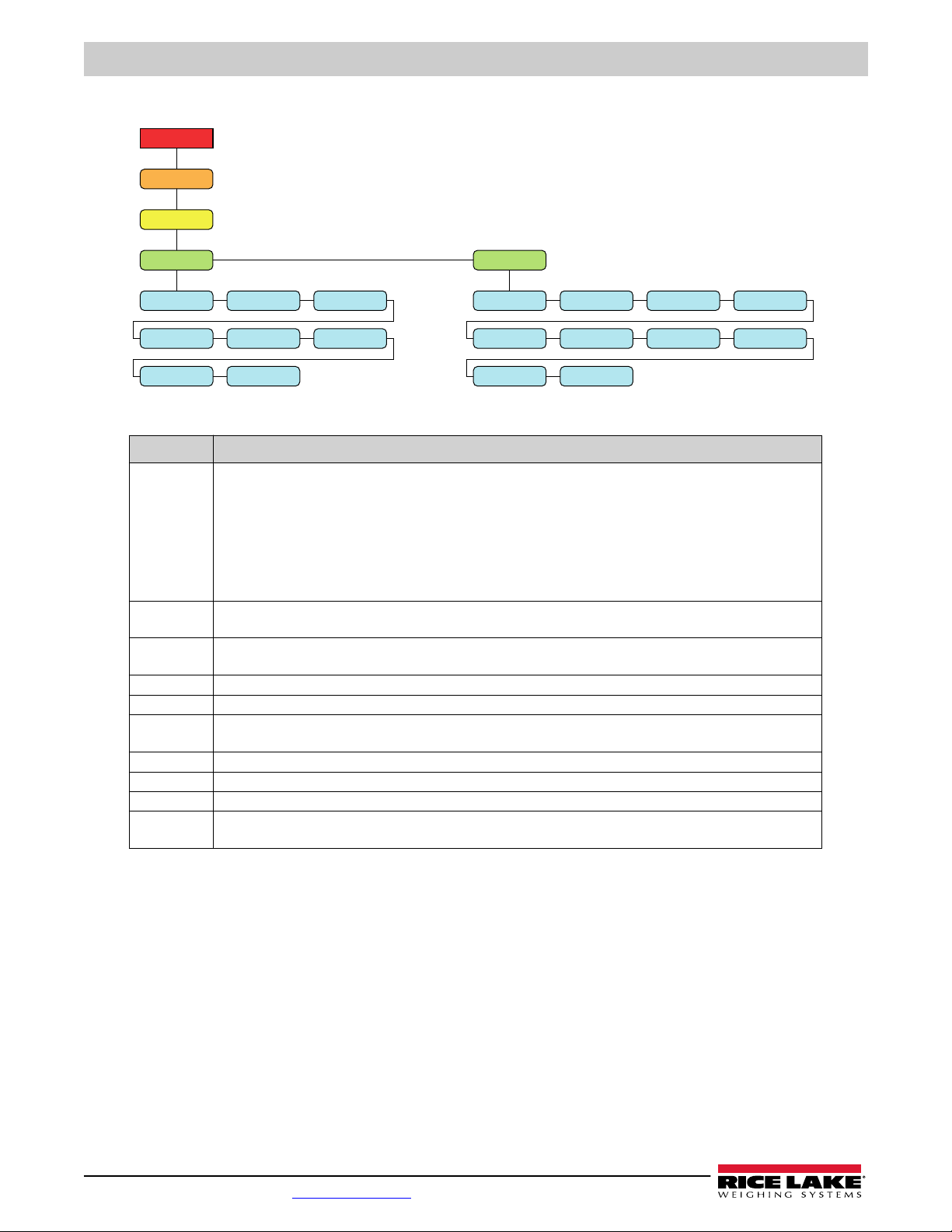
680 Synergy Plus
Setup
Comm
SERIAL
trigger BAUD
RS232 1-2
BITS
StopBIT TERMIN EOLDLY
ECHO ReSPNSE
trigger BAUD
RS485
BITS
TERMIN EOLDLY ECHO
address duplex
StopBIT
ReSPNSE
4.4.4.1 Serial Port Menu
Parameter Description
trigger Trigger – Sets the input trigger type; Settings:
NOTE: When in STRIND, STRLFT and REMOTE, if the COMM port is set to RS485, the port does not stream data
baud Baud Rate – Sets the transmission speed for the port; Settings: 1200, 2400, 4800, 9600 (default), 19200, 28800, 38400,
57600, 115200
bits Data Bits – Sets number of data bits transmitted or received by the port and specifies the parity bit to odd, even or none;
Settings: 8NONE (default), 8EVEN, 8ODD, 7EVEN, 7ODD
stopbit Stop Bits – Sets the number of stop bits transmitted or received by the port; Settings: 1 (default), 2
termin Outgoing Line Termination – Sets the termination character for data sent from the port; Settings: CR/LF (default), CR
eoldly End of Line Delay – Sets the delay period from when a formatted line is terminated to the beginning of the next
formatted serial output (measured in milliseconds); Enter value: 0–255, 0 (default)
echo Echo – Specifies if characters received by the port are echoed back to the sending unit; Settings: ON (default), OFF
respnse Response – Specifies if the port transmits replies to serial commands; Settings: ON (default), OFF
address Address – Specifies address used to connect to the port (RS-485/422 only); Enter value: 0–255, 0 (default)
duplex Duplex – Specifies FULL (4-wire) or HALF (2-wire) duplex used to connect to the port (RS-485/422 only);
Settings: FULL (default), HALF
Figure 4-9. Communication – Serial Port Menu
CMD (default) – Command: allows operation of EDP commands and printing
STRIND – Stream Industrial Scale Data: data is updated up to the configured sample rate; allows operation of
EDP commands and printing
STRLFT – Stream Legal for Trade Data: data is updated at the configured display update rate; allows operation of
EDP commands and printing
REMOTE – Configures the port to operate as a serial scale input
Table 4-8. Communication – Serial Port Menu Parameters
38 Visit our website www.RiceLake.com
Page 39
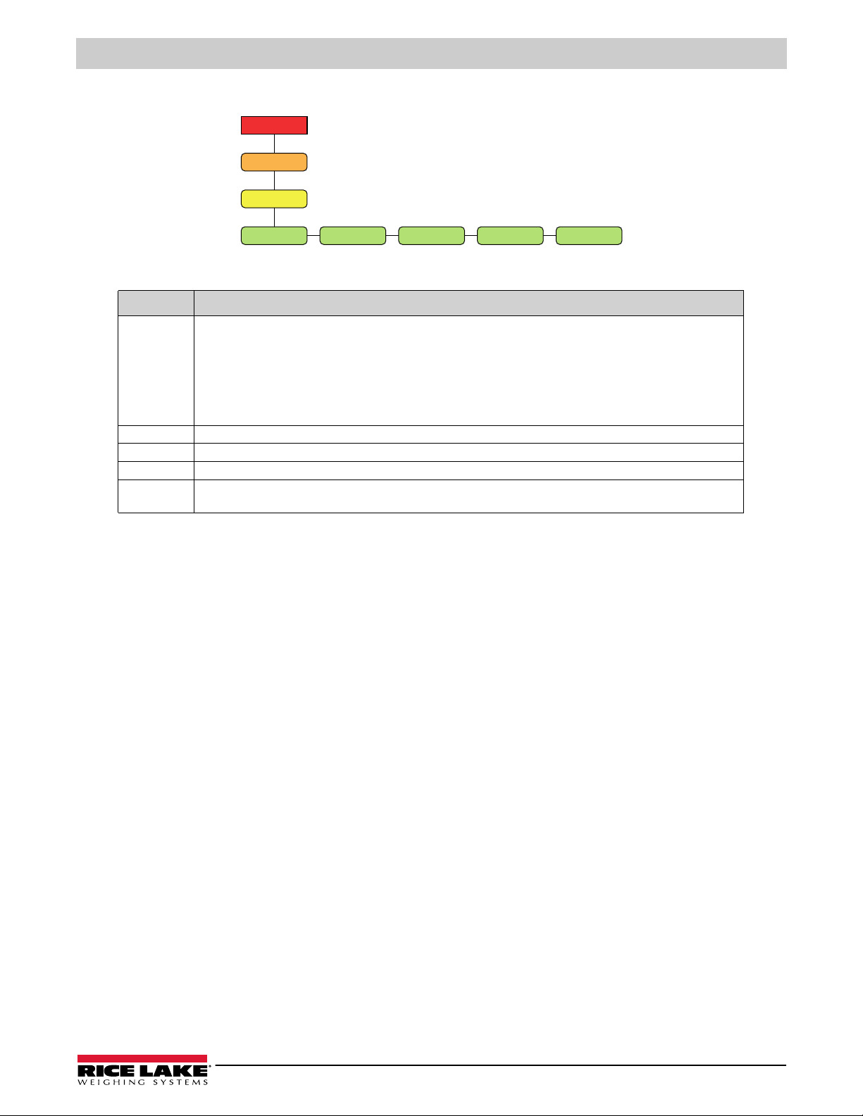
4.4.4.2 USB Menu
Setup
Comm
USB
trigger
termin ECHO ReSPNSE EOLDLY
Parameter Description
trigger Trigger – Sets the input trigger type; Settings:
termin Outgoing Line Termination – Sets the termination character for data sent from the port; Settings: CR/LF (default), CR
echo Echo – Specifies if characters received by the port are echoed back to the sending unit; Settings: ON (default), OFF
respnse Response – Specifies if the port transmits replies to serial commands; Settings: ON (default), OFF
eoldly End of Line Delay – Sets the delay period from when a formatted line is terminated to the beginning of the next
Configuration
Figure 4-10. Communication – USB Menu
CMD (default) – Command: setting input trigger to command allows operation of EDP commands and can print
STRIND – Stream Industrial Scale Data: data is updated up to the configured sample rate; allows operation of
EDP commands and printing
STRLFT – Stream Legal for Trade Data: data is updated at the configured display update rate; allows operation of
EDP commands and printing
REMOTE – Configures the port to operate as a serial scale input
formatted serial output (measured in milliseconds); Enter value: 0–255, 0 (default)
Table 4-9. Communication – USB Menu Parameters
© Rice Lake Weighing Systems ● All Rights Reserved 39
Page 40
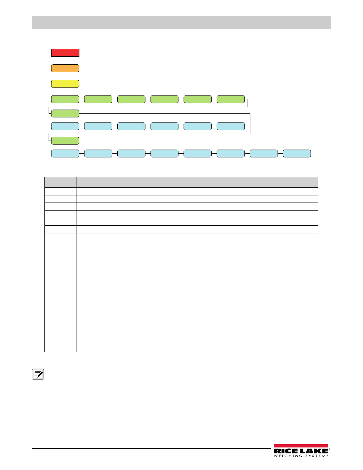
Setup
Comm
ETHrNET
DHCP
enabled IP ADDR subnet gateway
EThSRVR
trigger port termin ECHO respnse name
EthCLNT
trigger ip addr port TERMin eoldly echo respnse disctim
mac id
680 Synergy Plus
4.4.4.3 Ethernet Menu
Figure 4-11. Communication – Ethernet Menu
Parameter Description
mac id Mac ID – Read only; Settings: 00:00:00:00:00:00
dhcp DHCP – Dynamic Host Configuration Protocol (static allocation of IP address when OFF); Settings: ON (default), OFF
enabled Enabled – Enables Ethernet communications; Settings: OFF (default), ON
ip addr IP Address; Enter value: 0.0.0.0
subnet Subnet Mask; Enter value: 255.255.255.0
gateway Default Gateway; Enter value: 0.0.0.0
ethsrvr Ethernet Server – Allows the 680 to receive external EDP commands; Sub-parameters:
TRIGGER – Sets the input trigger type; Settings: CMD (default), STRIND, STRLFT, REMOTE
PORT – Specifies IP Address port to open to establish communications; Enter value: 1025–65535, 10001 (default)
TERMIN – Line Termination: Sets the termination character for data sent from the port; Settings: CR/LF (default), CR
ECHO – Specifies if characters received by the port are echoed back to the sending unit; Settings: OFF (default), ON
RESPNSE – Specifies if the port transmits replies to serial commands; Settings: ON (default), OFF
NAME – Host name for Ethernet Server; Enter characters: Alphanumeric entry up to 30 characters, 0 (default)
ethclnt Ethernet Client – Allows the 680 to send EDP commands to external devices; Sub-parameters:
TRIGGER – Sets the input trigger type; Settings: CMD (default), STRIND, STRLFT, REMOTE
IP ADDR – IP Address; Enter value: 0.0.0.0
PORT – Specifies IP Address port to look for to establish communications; Enter value: 1025–65535, 10001 (default)
TERMIN – Line Termination: Sets the termination character for data sent from the port; Settings: CR/LF (default), CR
EOLDLY – End of Line Delay: Sets the delay period from when a formatted line is terminated to the beginning of the
next formatted serial output (measured in milliseconds); Enter value: 0–255, 0 (default)
ECHO – Specifies if characters received by the port are echoed back to the sending unit; Settings: ON (default), OFF
RESPNSE – Specifies if the port transmits replies to serial commands; Settings: ON (default), OFF
DISCTIM – Disconnect Timeout (in seconds); Enter value: 0–60, 0 (default)
Table 4-10. Communication – Ethernet Menu Parameters
NOTE: A space is not a valid character in an address string. Pressing the ENTER key inserts a space to the left of the
current character, if the character limit has not been reached. See Section 3.3.2 on page 27 for complete instructions on
the alphanumeric entry procedure.
40 Visit our website www.RiceLake.com
Page 41
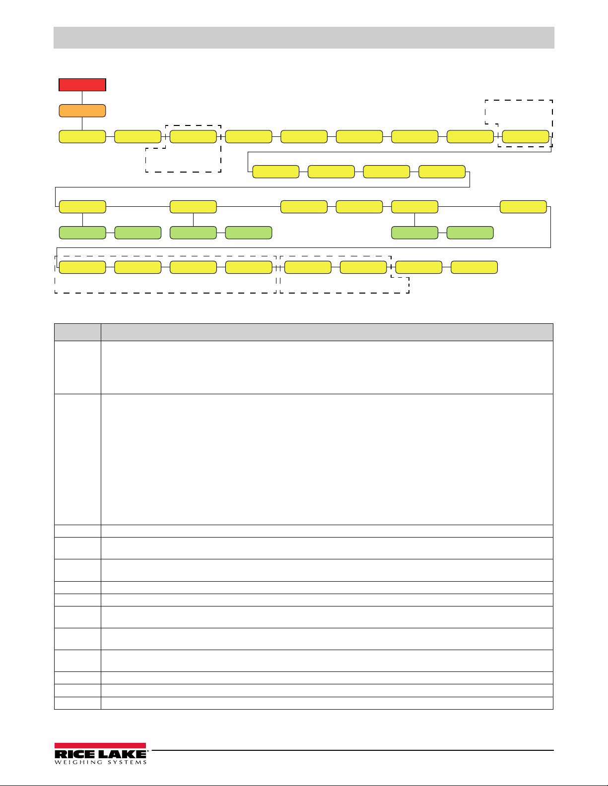
4.4.5 Program Menu
Setup
Progrm
Pwrupm Regula indset
Datefmt Datesep
Date
Timefmt Timesep
Time
Displays if regula
is set to indust
Consnu Uid contactconstu
wmtthrh maxwegh maxdatenumwegh
Accum
latorig eleorig latdest psttare rprtdeseledest
Displays if Locale is set to on
grvorig grvdest
Displays if Locale is set to factor
keyhold
hldtime intervl
LocaleKeylock zeronly
rtzgrad
Displays if accum
is set to on
Configuration
Figure 4-12. Setup – Program Menu
Parameter Description
pwrupm Power Up Mode – When the indicator is turned on, it performs a display test, then enters a warm up period; Settings:
GO (default) – Performs display test, then enters weigh mode after brief warm up period
DELAY – Performs display test, then enters a warm up period of 30 seconds
• If no motion is detected during warm up period, indicator enters weigh mode when warm up period ends
• If motion is detected, the 30 second timer is reset and the warm up period is repeated
regula
indset Industrial Settings – Displays when REGULA parameter is set to INDUST; See Section 4.4.5.2 on page 43
consnu Consecutive Numbering – Allows sequential numbering for print operations; the value is incremented following each print operation which
constu Consecutive Number Startup Value – Specifies the initial consecutive number (CONSNU) value used when the consecutive number is reset
uid Unit ID – Specifies the unit identification number with an alphanumeric value; Enter characters: Up to 8 alphanumeric characters, 1 (default)
contact Contact Information; See Section 4.4.5.1 on page 42
accum Accumulator – Accumulation can be toggled ON/OFF; if ON, accumulation occurs on print operation; if OFF, an accumulation
rtzgrad Return to Zero Grads – Number of graduations from the zero base at which the accumulator re-arms itself; only visible if the Accumulator
Wmtthrh Weighment Threshold – When the weight falls below the value set, the accumulator is rearmed;
Numwegh Number of Weighments – Displays the total number of weighments; Read only
Maxwegh Maximum Weighment – Displays the maximum weighment allowed; Read only
maxdate Date/Time of Max Weight – Displays the date and time the maximum weighment occurred; Read only
Regulatory Mode – Specifies the regulatory agency having jurisdiction over the scale site; the value specified for this parameter affects the
function of the front panel tare and zero keys; Settings: NTEP (default), OIML, CANADA, INDUST, NONE
• OIML, NTEP, and CANADA modes allow a tare to be acquired at a weight greater than zero; NONE allows tares to be acquired at
any weight value
• OIML, NTEP, and CANADA modes allow a tare to be cleared only if the gross weight is at no load; NONE allows tares to be cleared
at any weight value
• NTEP and OIML modes allow a new tare to be acquired even if a tare is already present; In CANADA mode, the previous tare must
be cleared before a new tare can be acquired
• NONE, NTEP and CANADA modes allow the scale to be zeroed in either gross or net mode as long as the current weight is within
the specified ZRANGE; In OIML mode, the scale must be in gross mode before it can be zeroed; pressing the ZERO key in net
mode clears the tare
• INDUST provides a set of sub-parameters to allow customization of tare, clear, and print functions in non Legal-for-Trade scale
installations
includes <CN> in the ticket format; Enter value: 0–9999999, 0 (default)
by sending CLRCN digital input; Enter value: 0–9999999, 0 (default)
does not occur; Settings: OFF (default), ON
(ACCUM) parameter is set to ON; Enter value: 0.0–100.0, 0.4 (default)
Enter value: 0.0–9999999.0, 1000.0 (default)
Table 4-11. Setup – Program Menu Parameters
© Rice Lake Weighing Systems ● All Rights Reserved 41
Page 42
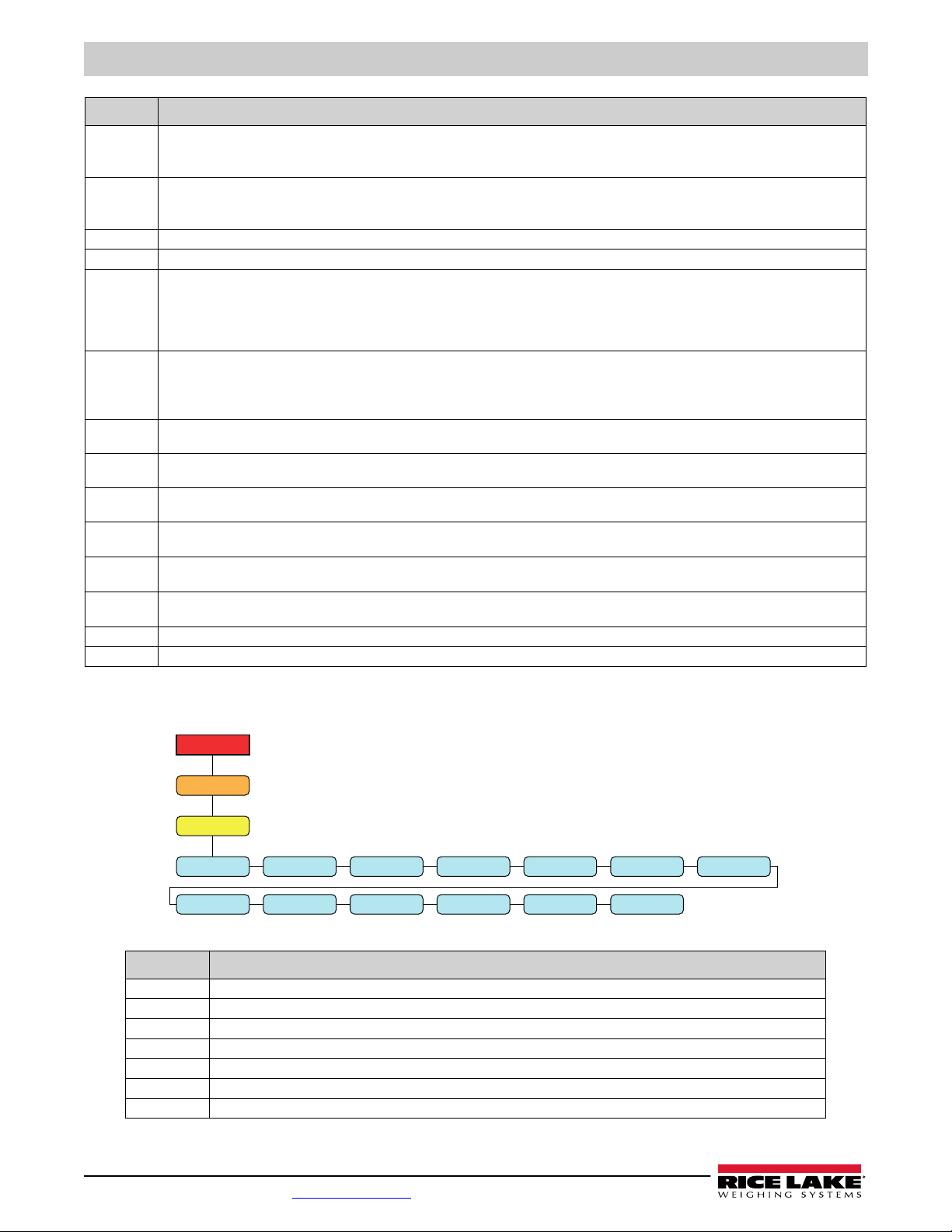
680 Synergy Plus
Setup
Progrm
contact
Company addr 1 addr 2
phone 1 phone 2 phone 3
addr 3 name 1
email lastcal
name 2 name 3
nextcal
Parameter Description
date Date – Allows setting of the date format and date separator character
DATEFMT – Date Format; Settings: MMDDYY (default), DDMMYY, YYMMDD, YYDDMM
DATESEP – Date Separator; Settings: SLASH (default), DASH, SEMI, DOT
time Time – Allows setting of the time format and the separator character
TIMEFMT – Time Format; Settings: 12HOUR (default), 24HOUR
TIMESEP – Time Separator; Settings: COLON (default), COMMA, DOT
keylock Keyboard Lock – Disables all keys except for the menu key and power key; Settings: OFF (Default), ON
zeronly Zero Only – Disables all keys except for the zero key, menu key and power key; Settings: Off (default), On
keyhold Key Hold – Allows setting of the key hold time and interval
HLDTIME – Key hold time (in tenths of a second); how long a key needs to be held before a key hold action is initiated;
20 equals 2 seconds; Enter value: 10–50, 20 (default)
INTERVL – Key hold time interval (in twentieths of a second); the amount of time between increments during a key hold;
2 equals a tenth of a second (10 increments per second during a key hold); Enter value: 1–100, 2 (default)
locale Location Gravity Compensation – Enables gravity compensation; Settings:
OFF (default) – gravity compensation disabled
ON – calculates gravity compensation using the origin and destination latitudes and elevations
FACTOR – uses origin and destination gravity factors to find gravity compensation
latorig Latitude of Origin – Original latitude (to nearest degree) for gravity compensation; displays when LOCALE parameter is set to ON;
eleorig Elevation of Origin – Original elevation (in meters) for gravity compensation; displays when LOCALE parameter is set to ON;
latdest Latitude of Destination – Destination latitude (to nearest degree) for gravity compensation; displays when LOCALE parameter is set to ON;
eledest Elevation of Destination – Destination elevation (in meters) for gravity compensation; displays when LOCALE parameter is set to ON;
grvorig
grvdest
PSttare Persistent Tare – Saves the tare value of scale on power cycle; Settings: Off (default), On
rPrtdes
Enter value: 0–90, 45 (default)
Enter value: -9999–9999, 345 (default)
Enter value: 0–90, 45 (default)
Enter value: -9999–9999, 345 (default)
2
Gravity of Origin – Original gravity factor (in m/s
Enter value: 9.00000–9.99999, 9.80665 (default)
Gravity of Destination – Destination gravity factor (in m/s
Enter value: 9.00000–9.99999, 9.80665 (default)
Remote Print Destination – Determines which indicator in the local/remote setup performs the print action; Settings: LOCAL (default), REMOTE
) for gravity compensation; displays when LOCALE parameter is set to FACTOR;
2
) for gravity compensation; displays when LOCALE parameter is set to FACTOR;
Table 4-11. Setup – Program Menu Parameters (Continued)
4.4.5.1 Contact Information Menu
Figure 4-13. Contact Information Menu
Parameter Description
company Company – Contact company name; Enter characters: Alphanumeric entry up to 30 characters
addr 1-3 Address – Contact company address lines; Enter characters: Alphanumeric entry up to 20 characters (for each line)
name 1-3 Name – Contact names; Enter characters: Alphanumeric entry up to 30 characters (for each line)
phone 1-3 Phone – Contact phone numbers; Enter characters: Alphanumeric entry up to 20 characters (for each line)
email Email – Contact email address; Enter characters: Alphanumeric entry up to 40 characters
lastcal Last Cal – Last calibration date; Enter value: 8-digit number (MMDDYYYY)
nextcal Next Cal – Next calibration date; Enter value: 8-digit number (MMDDYYYY)
Table 4-12. Contact Information Menu Parameters
42 Visit our website www.RiceLake.com
Page 43
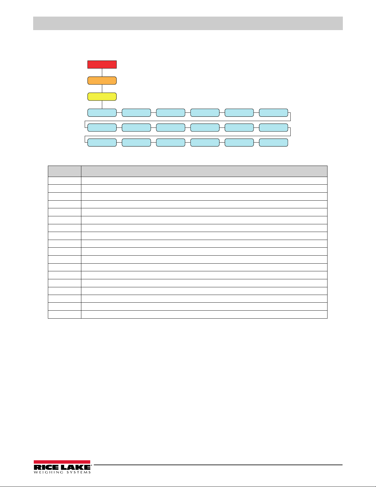
Configuration
Setup
Progrm
indset
AUDAGcY
NEGTOTl PRnTMOT PRinTPT
RKTARE AZT NET MCTARE
ZTARE KTARE
TAReMOT ZERoMOT
MTARE
MOToWGH
NTARE CTARE
OVRBASe RTARE
ULDWGH
4.4.5.2 Industrial Settings Menu
The industrial settings menu (indset) only displays if the regulation parameter (regula) is set to industrial (indust).
Figure 4-14. Industrial Settings Menu
Parameter Description
audagcy Audit Agency – Audit trail display agency format; Settings: NTEP (default), CANADA, NONE, OIML
ztare Zero Tare – Remove tare on zero; Settings: NO (default), YES
ktare Keyed Tare – Always allow keyed tare; Settings: YES (default), NO
mtare Multiple Tare – Replaces existing tare when the tare key is pressed; Settings: REPLACE (default), REMOVE, NOTHING
ntare Negative/Zero Tare – Allow negative or zero tare; Settings: NO (default), YES
ctare Clear Tare/Accumulator – Allow clear key to clear tare/accumulator; Settings: YES (default), NO
negtotl Negative Total – Allow total scale to display negative value; Settings: NO (default), YES
Prntmot Print In Motion – Allow print while in motion; Settings: NO (default), YES
printpt Print Preset Tare – Add preset tare (PT) to keyed tare print; Settings: YES (default), NO
motowgh Motion Weighment – Allow weighment in motion; Settings: NO (default), YES
ovrbase Overload Base – Zero base for overload calculation; Settings: CALIB (default), SCALE
rtare Round Button Tare – Round pushbutton tare to the nearest display division; Settings: NO (default), YES
rktare Round Keyed Tare – Round keyed tare to the nearest display division; Settings: NO (default), YES
azt net AZT On Net Value – Perform auto zero tracking on net value; Settings: NO (default), YES
mctare Manual Clear Tare – Allow manual clearing of the tare value; Settings: YES (default), NO
taremot Tare In Motion – Allow tare in motion; Settings: NO (default), YES
zeromot Zero In Motion – Allow scale to be zeroed while in motion; Settings: NO (default), YES
uldwgh Underload Weight – Underload weight value in display divisions; Enter value: 1–9999999, 20 (default)
Table 4-13. Industrial Settings Menu Parameters
© Rice Lake Weighing Systems ● All Rights Reserved 43
Page 44
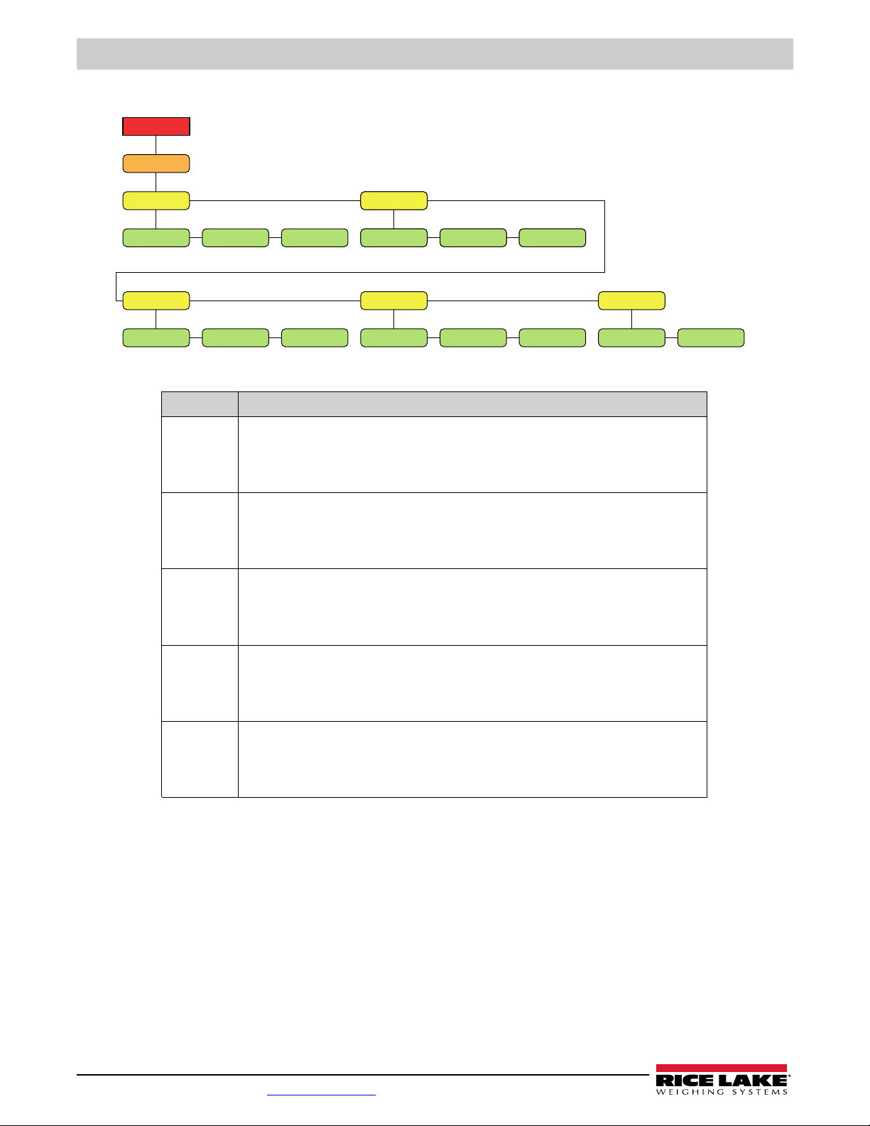
680 Synergy Plus
Setup
Pformt
format dest 1 dest 2
Nfmt
format dest 1 dest 2
Gfmt
Format dest 1 dest 2
Acumfmt
Format dest 1 dest 2
Stptfmt
format dest 1 dest 2
Nfmt
hdrFmt1 hdrFmt2
Hdrfmt
4.4.6 Print Format Menu
Parameter Description
gfmt Gross Format – Gross demand print format string
nfmt Net Format – Net demand print format string
acumfmt Accumulator Format – Accumulator print format string
stptfmt Setpoint Format – Setpoint print format string
hdrfmt Header Format – Ticket header format strings
Figure 4-15. Setup – Print Format Menu
FORMAT – Enter characters: Alphanumeric entry up to 1000 characters,
Gross<g><nl2><td><nl> (default)
DEST 1-2 – Destination ports; Settings: RS232-1 (default), RS232-2, RS485, TCPC, TCPS,
USB, NONE (DEST 2 default)
FORMAT – Enter characters: Alphanumeric entry up to 1000 characters,
Gross<g><nl>Tare<sp><t><nl>Net<sp2><n><nl2><td><nl> (default)
DEST 1-2 – Destination ports; Settings: RS232-1 (default), RS232-2, RS485, TCPC, TCPS,
USB, NONE (DEST 2 default)
FORMAT – Enter characters: Alphanumeric entry up to 1000 characters,
Accum <a><nl><da> <ti><nl> (default)
DEST 1-2 – Destination ports; Settings: RS232-1 (default), RS232-2, RS485, TCPC, TCPS,
USB, NONE (DEST 2 default)
FORMAT – Enter characters: Alphanumeric entry up to 1000 characters,
<scv><sp><spm><nl> (default)
DEST 1-2 – Destination ports; Settings: RS232-1 (default), RS232-2, RS485, TCPC, TCPS,
USB, NONE (DEST 2 default)
HDRFMT1 – Header 1 Format String; Enter characters: Alphanumeric entry up to 1000
characters, Company Name<nl>Street Address<nl>City St Zip<nl2> (default)
HDRFMT2 – Header 2 Format String; Enter characters: Alphanumeric entry up to 1000
characters, Company Name<nl>Street Address<nl>City St Zip<nl2> (default)
Table 4-14. Setup – Print Format Menu Parameters
44 Visit our website www.RiceLake.com
Page 45
Configuration
Setup
sformt
sformat
custom
gross tare net neg pripos
zerosec range okmotion invalid
units
Displays if
sformAt is
set to
custom
4.4.7 Stream Format Menu
Figure 4-16. Setup – Stream Format Menu
Parameter Description
sformat Stream Format – Specifies the stream format used for streaming output of scale data or specifies the expected input for a serial scale;
units Units – Specifies whether the streaming unit tokens remain static or dynamically updated with the configured units; Static uses set
custom Custom Stream Format – Specifies the custom stream format; only displays if SFORMAT is set to CUSTOM; see Section on page 79 for
gross Gross – Mode token when streaming the gross weight; Enter characters: Alphanumeric entry up to 8 characters, G (default)
tare Tare – Mode token when streaming the tare weight; Enter characters: Alphanumeric entry up to 8 characters, T (default)
net Net – Mode token when streaming the net weight; Enter characters: Alphanumeric entry up to 8 characters, N (default)
pos Positive – Polarity token when the weight is positive; Settings: SPACE (default), NONE, +
neg Negative – Polarity token when the weight is negative; Settings: SPACE, NONE, – (default)
pri Primary – Units token when streaming primary units; Enter characters: Alphanumeric entry up to 8 characters, L (default)
sec
zero
motion Motion – Status token when the weight is in motion; Enter characters: Alphanumeric entry up to 2 characters, M (default)
range Range – Status token when the weight is out of range; Enter characters: Alphanumeric entry up to 2 characters, O (default)
ok OK – Status token when the weight is OK (not invalid, out of range, at zero or in motion);
invalid Invalid – Status token when streaming an invalid weight; Enter characters: Alphanumeric entry up to 2 characters, I (default)
see Section 11.3 on page 77 for details on the stream output formats; Settings:
RLWS (default) – Rice Lake Weighing Systems stream format
CARDNAL – Cardinal stream format
WTRONIX – Avery Weigh-Tronix stream format
TOLEDO – Mettler Toledo stream format
MINEBEA - Minebea stream format
CUSTOM – Custom stream format
NOTE: Custom parameter is for input only. When set to remote, the port does not stream data (see Table 4-8 on
page 38).
Primary/Secondary unit tokens and Dynamic defaults to configured units of the scale; Settings: STATIC (default), DYNAMIC
available stream format tokens; Enter characters: Alphanumeric entry up to 1000 characters
Secondary – Units token when streaming secondary units; Enter characters: Alphanumeric entry up to 8 characters, K (default)
Zero – Status token when the weight is at center of zero; Enter characters: Alphanumeric entry up to 2 characters, Z (default)
Enter characters: Alphanumeric entry up to 2 characters (default is a space)
Table 4-15. Setup – Stream Format Menu Parameters
© Rice Lake Weighing Systems ● All Rights Reserved 45
Page 46
680 Synergy Plus
Setup
setpnt
batchng
setpt 1 Setpt 2-8
stptcfg
kind
off gross net -gross -net accum posrel negrel pctrel
pause delay waitss counter autojog coz inmoton inrange batchpr
timer concur tod always never
setpt 1-8
stptcfg
kind value trip bandval hysters preact preval preadj prestab
pcount rel num alarm clracum clrtare psh acc pshprnt pshtare dslot
dig out sense batch branch enable access alias
If TRIP = INBAND
or OUTBAND
If TRIP = HIGHER
or LOWER
If PREACT =
ON or LEARN
If PREACT = LEARN
If PREACT = LEARN If KIND = POSREL,
NEGREL or PCTREL
Based on DIGIO
set as OUTPUT
If BATCH = ON
4.4.8 Setpoints Menu
Section 4.4.8.3
on page 47
Section 4.4.8.1
Section 4.4.8.3
on page 47
Section 4.4.8.3 on page 47
Section 4.4.8.1
Section 4.4.8.2 on page 47 Section 4.4.8.3 on page 47
Section 4.4.8.2
on page 47
Section 4.4.8.3
on page 47
Section 4.4.8.2
on page 47
Figure 4-17. Setup – Setpoints Menu
Parameter Description
stptcfg Setpoint Configuration – Access to configuration parameters and settings for up to eight setpoints; Settings: SETPT 1-8
KIND – Setpoint Kind: Settings: OFF (default), GROSS, NET, -GROSS, -NET, ACCUM, POSREL, NEGREL, PCTREL, PAUSE, DELAY,
WAITSS, COUNTER, AUTOJOG, COZ, INMOTON, INRANGE, BATCHPR, TIMER, CONCUR, TOD, ALWAYS, NEVER
batchng Batching – Batch sequence runs when set to AUTO or MANUAL; Settings:
OFF (default)
AUTO – Allows the batch sequence to repeat automatically once it has been started
MANUAL – Requires a BATSTRT input/command to run the batch sequence
Table 4-16. Setup – Setpoints Menu Parameters
4.4.8.1 If KIND = GROSS, NET, -GROSS, -NET, POSREL, NEGREL, PCTREL
46 Visit our website www.RiceLake.com
Figure 4-18. Setpoints – Parameter Group A
Page 47
4.4.8.2 If KIND = ACCUM, DELAY, WAITSS, AUTOJOG, TOD
setpt 1-8
stptcfg
kind value trip bandval time durtn alarm
clracum clrtare psh acc pshprnt pshtare dslot dig out sense batch
branch access enable alias
If KIND = ACCUM
or DELAY
If KIND = TOD
If KIND = ACCUM
or TOD
If BATCH = ON and
KIND = ACCUM
If KIND = ACCUM
If KIND = ACCUM If TRIP = INBAND
or OUTBAND
If KIND = ACCUM,
DELAY or WAITSS
setpt 1-8
stptcfg
kind value start end dslot dig out sense branch
access alias
If KIND = COUNTER,
TIMER or CONCUR
If KIND = COUNTERIf KIND = TIMER or CONCUR
Figure 4-19. Setpoints – Parameter Group B
4.4.8.3 If KIND = PAUSE, COUNTER, COZ, INMOTON, INRANGE, BATCHPR, TIMER, CONCUR
Configuration
Figure 4-20. Setpoints – Parameter Group C
Parameter Description
value Setpoint Value – For weight-based setpoints: Enter value: 0.0–9999999.0, 0.0 (default)
For time-based setpoints: Enter value: 0.0–65535.0, 0.0 (default)
For COUNTER setpoints: Enter value: 0.0–65535.0, 0.0 (default)
trip Trip – Specifies whether the setpoint is satisfied when the weight is higher or lower than the setpoint value, within a band established
around the value, or outside of the band; in a batch sequence with TRIP=HIGHER, the associated digital output is active until the setpoint
bandval Band Value – For setpoints with TRIP=INBAND or OUTBAND, specifies a weight equal to half the band width; The band established
hysters Hysteresis – Specifies a band around the setpoint value which must be exceeded before the setpoint, once off, can trip
preact Preact Type – Allows the digital output associated with a setpoint to shut off before the setpoint is satisfied to allow for
value is reached or exceeded; with TRIP=LOWER, the output is active until the weight goes below the setpoint value; Settings: HIGHER
(default), LOWER, INBAND, OUTBAND
around the setpoint value is VALUE ±BNDVAL; Enter value: 0.0–9999999.0, 0.0 (default)
on again; Enter value: 0.0–9999999.0, 0.0 (default)
material in suspension; Settings: OFF (default)
ON – Adjusts setpoint trip value up or down (depending on the TRIP parameter setting) from setpoint value using a fixed value
specified on the PREVAL parameter
LEARN – Can be used to automatically adjust the PREACT value after each batch; it compares the actual weight at standstill to the
target setpoint value and adjusts the PREVAL by the PREADJ value times the difference after each batch
Table 4-17. Kind Parameter Descriptions
© Rice Lake Weighing Systems ● All Rights Reserved 47
Page 48
680 Synergy Plus
Parameter Description
start Starting Setpoint – Specifies starting setpoint number; do not specify number of the TIMER or CONCUR setpoint itself; TIMER or
CONCUR setpoint begins when starting setpoint begins; Enter value: 1–8, 1 (default)
end Ending Setpoint – Specifies ending setpoint number; do not specify number of the TIMER or CONCUR setpoint itself; TIMER or CONCUR
setpoint stops when ending setpoint begins; Enter value: 1–8, 1 (default)
time Time – For TOD setpoints, specifies the time at which the setpoint becomes active; the format used to enter the time (12hour or 24hour)
is based on the value specified for the TIMEFMT parameter in the Program menu (HHMM); Enter value: 0000 (default)
duraton Duration – For TOD setpoints; specifies the length of time the digital output associated with this setpoint changes state; value is entered in
hours, minutes, and seconds (HHMMSS); Enter value: 000000 (default)
preval Preact Value – Specifies the preact value for setpoints with PREACT set to ON or LEARN; depending on the TRIP setting specified for the
setpoint, the setpoint trip value is adjusted up or down by the PREVAL value; Enter value: 0.0–9999999.0, 0.0 (default)
preadj Preact Adjustment – Setpoints with PREACT set to LEARN, specifies a decimal representation of the percentage of error correction
applied (50.0 = 50%, 100.0 = 100%) each time a PREACT adjustment is made; Enter value: 0.0–100.0, 50.0 (default)
prestab Preact Stabilization Time-Out – Setpoints with PREACT set to LEARN, specifies the time, in 0.1-sec intervals, to wait for standstill before
adjusting the PREACT value; setting this parameter to a value greater than zero disables the learn process if standstill is not achieved in
the specified interval (in tenths of a second); Enter value: 0–65535, 0 (default)
pcount Preact Learn Interval Count – Setpoints with PREACT set to LEARN, specifies the number of batches after which the preact value is
recalculated; the default value, 1, recalculates the preact value after every batch cycle; Enter value: 1–65535, 1 (default)
rel num Relative Number – For relative setpoints, specifies the number of the relative setpoint; Enter value: 1–8, 1 (default)
Target weight for this setpoint is determined as follows:
POSREL setpoints, the value of the relative setpoint plus the value (VALUE parameter) of the POSREL setpoint
N E G
REL setpoints, the value of the relative setpoint minus the value of the
PCTREL setpoints, the percentage (specified on VALUE parameter of the PCTREL setpoint) of the target value of the relative
setpoint
alarm Alarm – Specify ON to display the word ALARM on the primary display while the setpoint is active (batch setpoints) or while the setpoint is
not tripped (continuous setpoints); Settings: OFF (default), ON
clracum Clear Accumulator – Specify ON to clear the accumulator when the setpoint is satisfied; Settings: OFF (default), ON
clrtare Clear Tare – Specify ON to clear the tare when the setpoint is satisfied; Settings: OFF (default), ON
psh acc Push Accumulator – Specify ON to update the accumulator and perform a print operation when the setpoint is satisfied; specify ONQUIET
to update the accumulator without printing; Settings: OFF (default), ON, ONQUIET
pshprnt Push Print – Specify ON to perform a print operation when the setpoint is satisfied; specify WAITSS to wait for standstill after setpoint is
satisfied before printing; Settings: OFF (default), ON, WAITSS
pshtare Push Tare – Specify ON to perform an acquire tare operation when the setpoint is satisfied; Settings: OFF (default), ON
NOTE: PSHTARE acquires the tare regardless of the value specified for the REGULA parameter in the Program menu
dslot Digital Output Slot – Lists all available digital I/O slots; this parameter specifies the slot number of the digital I/O card referenced by the
DIG OUT parameter; Settings: NONE (default), 0
dig out Digital Output – Lists all digital output bit numbers available for the specified digital output slot; this parameter is used to specify the digital
output bit associated with this setpoint; use the DIGIO menu to assign bit function to OUTPUT; Enter value: 1–4, 1 (default)
NOTE: For continuous setpoints, the digital output becomes active (low) when the condition is met; for batch setpoints, the digital output is
active until the setpoint condition is met
sense Sense – Specifies whether the value of the digital output associated with this setpoint is inverted when the setpoint is satisfied; Settings:
NORMAL (default), INVERT
batch Batch – Specifies whether the setpoint is used as a batch (ON) or continuous (OFF) setpoint; Settings: OFF (default), ON
branch Branch Destination – Specifies the setpoint number to which the batch sequence is to branch, if the current setpoint is not satisfied upon
initial evaluation (0 = do not branch); Enter value: 0–8, 0 (default)
enable Enable – Specifies if setpoint parameters display in user mode; Settings: ON (default), OFF
access Access – Specifies the access allowed to setpoint parameters in user mode; Settings:
ON (default) – Values can be displayed and changed
HIDE – Values cannot be displayed or changed
OFF – Values can be displayed but not changed
alias Alias – Name for the setpoint; Enter characters: Alphanumeric entry up to 8 characters, SETPT (default)
N E G
REL setpoint
Table 4-17. Kind Parameter Descriptions (Continued)
48 Visit our website www.RiceLake.com
Page 49
4.4.9 Digital I/O Menu
Setup
DIGIO
bit 3 bit 4bit 1 bit 2
slot 0
Setup
ALGOUT
modeSOURCE OUTPUT ERRACT MIN MAX twzero twspan
Displays if regula is set to indust
Figure 4-21. Setup – Digital I/O Menu
Parameter Description
bit 1-4 Digital I/O Bit 1-4 – Specifies the mode and function of the digital I/O pins; Settings: OFF (default), PRINT, ZERO,
TARE, UNITS, PRIM, SEC, CLEAR, DSPACC, DSPTAR, CLRACC, CLRTAR, NT/GRS, GROSS, NET, CLRCN,
KBDLOC, BATRUN, BATSTRT, BATPAUS, BATRESE, BATSTOP, OUTPUT
Table 4-18. Setup – Digital I/O Menu Parameters
4.4.10 Analog Output Menu
Instructions to install and setup the analog output option card are provided with the option card kit (PN 195084).
Configuration
Parameter Description
source Source – Specifies the scale tracked by the analog output; only appears if the Regulatory Mode (REGULA) parameter is set to
mode Mode – Specifies the weight data, gross or net, tracked by the analog output when the Source parameter is assigned to a scale;
output Output – Specifies the voltage or current tracked by the analog output; Settings: 0-10V (default), 0-20MA, 4-20MA
erract Error Action – Specifies how the analog output responds to system error conditions; Settings:
min Minimum Weight – Specifies the minimum weight value tracked by the analog output; Enter value: ±9999999.0, 0.0 (default)
max Maximum Weight – Specifies the maximum weight value tracked by the analog output; Enter value: ±9999999.0, 10000.0 (default)
twzero Tweak Zero – Adjusts the offset of the analog output zero value; Enter value: 0–65535, 0 (default)
twspan Tweak Span – Adjusts the offset of the analog output span value; Enter value: 0–65535, 59515 (default)
Figure 4-22. Setup – Analog Output Menu
Industrial (INDUST) in the Program menu (Section 4.4.5 on page 41); Settings: SCALE 1 (default), REMOTE
Settings: GROSS (default), NET
FULLSC (default) – Set to full scale (10 V or 20 mA)
HOLD – Holds current value
ZEROSC – Sets to zero value (0 V, 0 mA or 4 mA)
Table 4-19. Setup – Analog Output Menu Parameters
© Rice Lake Weighing Systems ● All Rights Reserved 49
Page 50
680 Synergy Plus
ACCUM
dispacm
prtACum CLRACum
TARE
disptar
CLRTARe
4.5 Accumulator Menu
Parameter Description
dispacm Display Accumulator – Displays the accumulator value; Read Only
prtacum Print Accumulator – Prints the accumulator value to specified port, if setup
clracum Clear Accumulator – Clears the accumulator value
4.6 Tare Menu
Figure 4-23. Accumulator Menu
Table 4-20. Accumulator Menu Parameters
Figure 4-24. Tare Menu
Parameter Description
disptar Display Tare – Displays the current tare value; Read Only
clrtare Clear Tare – Clears the current tare value
Table 4-21. Tare Menu Parameters
50 Visit our website www.RiceLake.com
Page 51
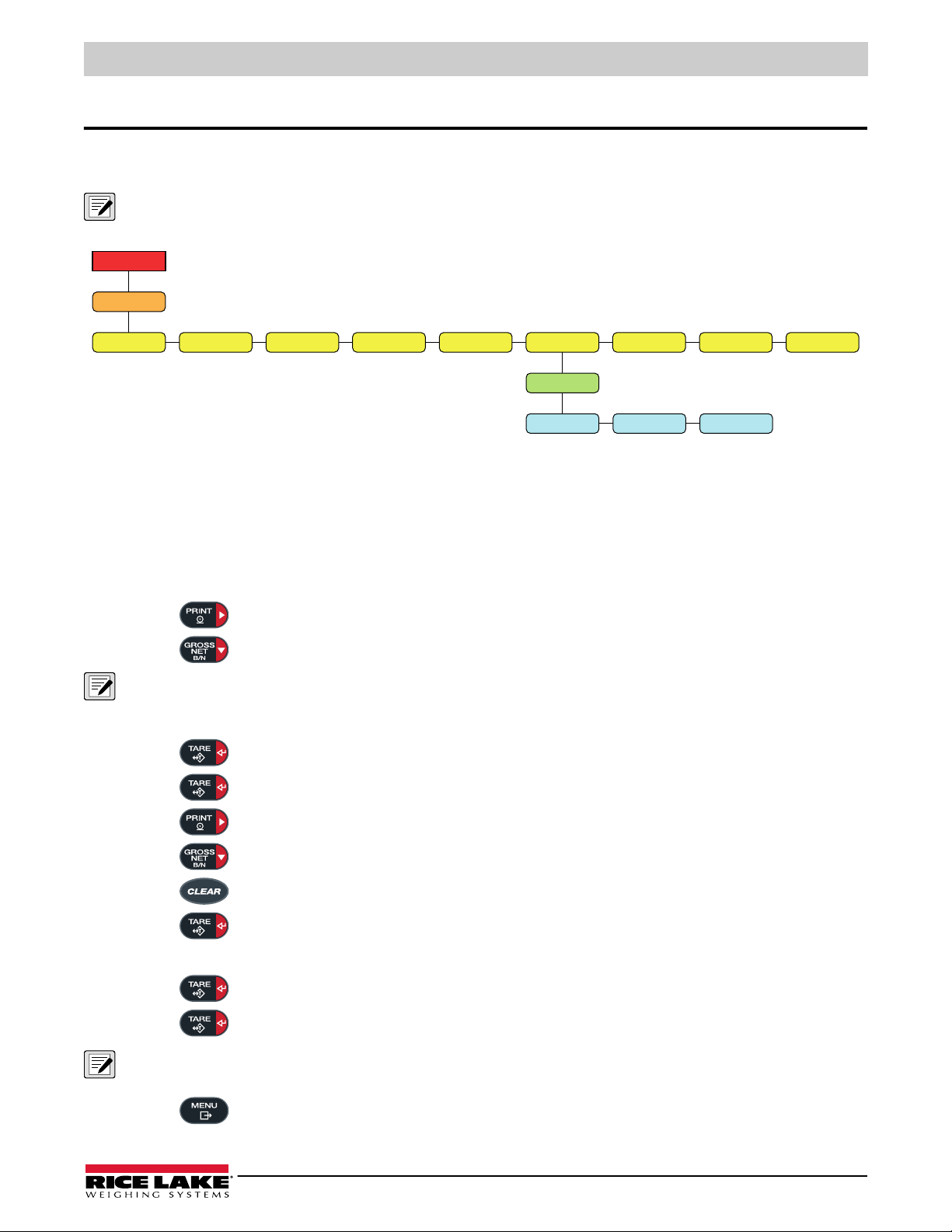
Calibration
Setup
Calibr
zerocntWZERO WVAL spancntWSPAN
Point 1-4
WLIN REZERO
Wlin v1-4 wlin c1-4 wlin f1-4
lstzero tmpzero
5.0 Calibration
The 680 can be calibrated using the front panel and EDP commands. The following sections describe the procedures required
for these calibration methods.
NOTE: The 680 requires a WZERO and WSPAN points to be calibrated. The linear calibration points are optional; they must
fall between zero and span, but must not duplicate zero or span.
Figure 5-1. Calibration Menu
5.1 Front Panel Calibration
5.1.1 Span Calibration
Use the following steps to perform a standard span calibration on a connected scale.
1. Access the setup menu by pressing the setup switch (Section 4.1 on page 32).
2. Press twice.
3. Press .
NOTE: See Section 5.2 on page 52 if the application requires a rezero, last zero or temporary zero.
Calibr displays.
wzero displays.
4. Ensure there is no weight on the scale.
5. Press to perform a zero calibration.
6. Press .
7. Press .
zerocnt displays. See Section 4.4.3 on page 36 for more information on zerocnt.
wval displays.
ok displays.
8. Press . The current test weight value displays.
9. Press and use the numeric keypad to enter a new value, if necessary.
10. Press to accept value.
wSpan displays and the indicator is ready for test weight.
11. Place the specified amount of test weight on the scale.
12. Press to perform a span calibration.
ok displays.
Config displays.
13. Press .
NOTE: Span calibration is complete. To continue with a linear calibration, see Section 5.1.2 on page 52 before returning to
weigh mode.
spancnt displays. See Section 4.4.3 on page 36 for more information on zpancnt.
14. Press to return to weigh mode.
© Rice Lake Weighing Systems ● All Rights Reserved 51
Page 52
680 Synergy Plus
5.1.2 Linear Calibration
Linear calibration points provide increased scale accuracy by calibrating the indicator at up to four additional points between the
zero and span calibrations.
1. Complete steps 1–13 in Section 5.1.1 on page 51. Press .
2. Press .
3. Press .
4. Press . The current test weight value for point 1 displays.
5. Press and use the numeric keypad to enter a new value, if necessary.
6. Press to accept value.
7. Place the specified amount of test weight on the scale.
8. Press to perform a linear point calibration.
9. Press .
10. Press .
11. Press .
12. Repeat previous steps for points 2-4, if necessary.
NOTE: The linear calibration for a point is saved once point is calibrated.
13. Press to return to weigh mode.
point1 displays.
wlin v1 displays.
wlin c1 displays and the indicator is ready for test weight.
ok displays.
wlin f1 displays. See Section 4.4.3 on page 36 for more information on WLIN F#.
Point1 displays.
Point 2 displays.
wlin displays.
5.2 Alternative Zero Calibrations
During a calibration, the zero value (wzero) can be replaced with a temporary zero (tmpzero) or last zero (lstzero). A
rezero (
5.2.1 Last Zero
This takes the last push-button zero in the system (from weigh mode) and uses it as the new zero reference point, after which a
new span calibration must be performed. This calibration cannot be performed when calibrating a scale for the first time.
A last zero calibration is typically used on truck scales to allow a scale verification to become a calibration without having to
remove the test weights.
5.2.2 Temporary Zero
A temporary zero calibration temporarily zeros the displayed weight of a non-empty scale. After span calibration, the difference
between the temporary zero and the previously calibrated zero value is used as an offset.
A temporary zero calibration is typically used on hopper scales to calibrate the span without losing the original zero calibration.
5.2.3 Rezero
A rezero calibration is needed to remove a calibration offset when hooks or chains are required to suspend the test weights.
Once a span calibration is complete, remove the hooks or chains and the test weights from the scale. With all the weight
removed, a rezero calibration is used to adjust the zero and span calibration values.
rezero) can be done after calibration. See below for information on these alternative zeros.
52 Visit our website www.RiceLake.com
Page 53

Calibration
5.3 EDP Command Calibration
Use the following instructions to calibrate the 680 using EDP commands. For information on the EDP commands of the 680,
see Section 7.0 on page 55.
NOTE: The indicator must respond with OK after each step or the calibration procedure must be done again.
1. Press the setup switch to place indicator in setup mode (Section 4.1 on page 32).
2. For a standard calibration, remove all weight from scale (except hooks or chains which are needed to attach weights).
3. Send the command SC.WZERO#1 to perform a standard calibration of the zero point.
• Send SC.TEMPZERO#1 to perform a temporary zero calibration
• Send SC.LASTZERO#1 to perform a last zero calibration
4. Apply the span calibration weight to the scale.
5. Send the command SC.WVAL#1=xxxxx, where xxxxx is the value of the span calibration weight applied to the scale.
6. Send the command SC.WSPAN#1 to calibrate the span point. Continue on to step 7 to calibrate additional
linearization points, or proceed to step 11.
7. Apply weight equal to the first linearization point to the scale.
8. Send the command SC.WLIN.Vn#1=xxxxx, where n is the linearization point number (1-4) and xxxxx is the exact
value of the weight applied.
9. Send the command SC.WLIN.Cn#1 to calibrate the linearization point, where n is the linearization point number (1-4).
10. Repeat steps 7–9 for up to four total linearization points.
11. If hooks or chains were used to attach the weights, remove all weight, including the hooks and chains, and send the
command SC.REZERO#1 to remove the zero offset.
12. Send the command KSAVEEXIT to return to weigh mode.
© Rice Lake Weighing Systems ● All Rights Reserved 53
Page 54

680 Synergy Plus
6.0 Revolution
The Revolution utility provides a suite of functions used to support configuration, calibration, customization and backup of the
680 software.
Calibration values and scale configuration can both be saved and restored to the 680 using Revolution.
NOTE: For system requirements visit the Revolution product page on Rice Lake Weighing Systems website.
6.1 Connecting to the Indicator
Connect the PC serial port to com 1 of the 680, then click Connect in the toolbar. Revolution attempts to establish
communications to the indicator. If communications settings need to be adjusted, select Options… from the Tools menu.
Downloading to the Indicator
The Send Configuration to Device function in the Revolution Communications menu allows a Revolution configuration file
(with or without scale calibration data) or ticket formats to be downloaded to a connected indicator in setup mode.
The Send Section to Device function in the Communications menu allows the download of only the currently displayed object,
such as a scale configuration.
Because less data is transferred using the Send Section to Device, it is typically faster than a full configuration download, but
there is an increased possibility the download fails due to dependencies on other objects. If the download fails, try performing a
complete download using the Send Configuration to Device function.
Uploading Configuration to Revolution
The Get Configuration from Device function in the Revolution Communications menu allows the existing configuration of a
connected indicator to be saved to a file on the PC. Once saved, the configuration file provides a backup which can be quickly
restored to the indicator if needed. Alternatively, the file can be edited within Revolution and downloaded back to the indicator.
6.2 Saving and Transferring Data
NOTE: Revolution has a module to save and transfer data. It is the preferred method over using ProComm or Hyper Terminal.
6.2.1 Saving Indicator Data to a Personal Computer
Configuration data can be saved to a computer connected to the selected port. The PC must be running a communications
program such as PROCOMMPLUS
When configuring the indicator, ensure the values set for the baud and bits parameters on the serial menu match the baud rate,
bits and parity settings configured for the serial port on the PC.
To save all configuration data, first put the communications program into data capture mode, then
mode and send the DUMPALL command to the indicator. The 680 responds by sending all configuration parameters to the PC
as ASCII-formatted text.
6.2.2 Downloading Configuration Data from PC to Indicator
Configuration data saved on a PC or disc can be downloaded from the PC to an indicator. This procedure is useful when a
number of indicators with similar configurations are set up or when an indicator is replaced.
To download configuration data, connect the PC to the selected port as described in Section 6.2.1. Place the indicator in setup
mode and use the PC communications software to send the saved configuration data to the indicator. When transfer is
complete, calibrate the indicator as described in Section 5.0 on page 51.
®
.
place the indicator in setup
6.3 Updating Firmware
Revolution is used to update the firmware of the 680 indicator. The link to begin this process is available on the Revolution
home screen. Updating the firmware defaults configuration settings.
54 Visit our website www.RiceLake.com
Page 55
EDP Commands
7.0 EDP Commands
The 680 indicator can be controlled by a personal computer connected to one of the indicator communication ports. Control is
provided by a set of commands which can simulate front panel key press functions, return and change setup parameters, and
perform reporting functions. The commands provide the capability to print configuration data or to save data to an attached
personal computer. This section describes the EDP command set and procedures for saving and transferring data using the
communication ports. The EDP command set is divided into several groups.
When the indicator processes a command, it either responds with a value (for reporting commands, or when querying
parameter settings), or with the message OK. The OK response verifies the command was received and has been executed. If
the command is unrecognized, the indicator responds with ?? invalid command. If the command cannot be executed in the
current mode, the indicator responds with ?? invalid mode. If the command is recognized, but the value is out of range or the
invalid type, the indicator responds with ?? followed by the type and the range.
7.1 Key Press Commands
Key press serial commands simulate pressing keys on the front panel of the indicator. These commands can be used in both
setup and weigh mode. Several of the commands serve as pseudo keys, providing functions which are not represented by a
key on the front panel.
For example, to enter a 15 lb tare weight using serial commands:
1. Type K1 and press
2. Type K5 and press
3. Type KTARE and press
Enter (or Return).
Enter.
Enter.
Command Function
KZERO In weigh mode, this command acts like pressing the Zero key
KGROSSNET In weigh mode, this command acts like pressing the Gross/Net key
KGROSS Displays Gross mode (pseudo key)
KNET Displays Net mode (pseudo key)
KTARE In weigh mode, this command acts like pressing the Tare key
KUNITS In weigh mode, this command acts like pressing the Units key
KMENU In weigh mode, this command acts like pressing the Menu key
KPRIM Displays primary units (pseudo key)
KSEC Displays secondary units (pseudo key)
KPRINT In weigh mode, this command acts like pressing the Print key
KPRINTACCUM Prints the accumulated weight
KDISPACCUM Displays the accumulator value
KDISPTARE Displays the tare value
KCLR In weigh mode, this command acts like pressing the Clear key
KCLRCN Clears consecutive number
KCLRTAR Clears the tare from the system (pseudo key)
KLEFT In setup mode, this command moves Left in the menu
KRIGHT In setup mode, this command moves Right in the menu
KUP In setup mode, this command moves Up in the menu
KDOWN In setup mode, this command moves Down in the menu
KEXIT In setup mode, this command exits to weigh mode
KSAVE In setup mode, this command saves the current configuration
KSAVEEXIT In setup mode, this command saves the current configuration and exits to weigh mode
KTIME Displays time
KDATE Displays date
KTIMEDATE Displays time and date
Table 7-1. Key Press Commands
© Rice Lake Weighing Systems ● All Rights Reserved 55
Page 56
680 Synergy Plus
Command Function
KCLRACCUM Clears the accumulator
Kn This command acts like pressing numbers 0 (zero) through 9
KDOT This command acts like pressing the decimal point (.)
KENTER This command acts like pressing the Enter key
KYBDLK In setup mode, this command locks the keys, except for the Menu key
KLOCK=x In setup mode, this command locks specified front panel key; x = KPRINT, KUNITS, KTARE, KGROSSNET, KZERO,
KUNLOCK=x In setup mode, this command unlocks specified front panel key; x = KPRINT, KUNITS, KTARE, KGROSSNET, KZERO,
K0-K9, KDOT, KCLEAR (example: to lock the Zero key, enter KLOCK=KZERO
K0-K9, KDOT, KCLEAR (example: to unlock the Print key, enter KUNLOCK=KPRINT
Table 7-1. Key Press Commands (Continued)
7.2 Reporting Commands
Reporting commands send specific information to the communications port. The commands listed in Table 7-2 can be used in
either setup mode or weigh mode.
Command Function
DUMPALL Returns a list of all parameter values
DUMPAUDIT Returns the Audit Trail information
KDUMPAUDIT Returns the Audit Trail information on the same port which the EDP command was sent
AUDIT.LRVERSION Returns the legally relevant firmware version
AUDIT.CONFIG Returns the number of times configuration has changed
AUDIT.CALIBRATE Returns the number of calibrations
AUDITJUMPER Returns the position of the audit jumper (ON or OFF)
SPDUMP Returns a list of the setpoint parameter values
VERSION Returns the firmware version
HARDWARE Returns the option card installed
HWSUPPORT Returns the CPU board part number
RTCBATTERYSTATUS Returns the status of the real time clock battery (GOOD or BAD)
Table 7-2. Reporting Commands
7.3 Reset Configuration Command
The following command can be used to reset the configuration parameters of the 680.
Command Function
RESETCONFIGURATION Restores all configuration parameters to default values (setup mode only)
Table 7-3. Reset Configuration Command
NOTE: All scale calibration settings are lost when the RESETCONFIGURATION command is run.
56 Visit our website www.RiceLake.com
Page 57
EDP Commands
7.4 Scale Parameter Setting Commands
Parameter setting commands allow the current value for a configuration parameter to be displayed or changed.
Current configuration parameter settings can be displayed in setup mode or weigh mode using the following syntax:
command<ENTER>
Most parameter values can be changed in setup mode only; setpoint parameters listed in Table 7-10 on page 61 can be
changed when in normal weigh mode.
NOTE: The user must stop the current batch for new values to take effect.
Use the following command syntax when changing parameter values: command=value<ENTER>, where value is either a
number or a parameter value. Use no spaces before or after the equal (=) sign. If an incorrect command is typed or an invalid
value is specified, the indicator returns ?? followed by the error message.
Example: to set the motion band parameter on Scale #1 to 5 divisions, type the following:
SC.MOTBAND#1=5<ENTER>
To return a list of the available values for parameters with specific values, enter the command and equal sign, followed by a
questions mark (command=?<ENTER>). The indicator must be in setup mode to use this function.
After changes are made to configuration parameters using EDP commands, use the KSAVE or KSAVEEXIT commands to
commit the changes to memory.
Command Description Values
SC.CAPACITY#n Scale capacity 0.0000001–9999999.0, 10000.0 (default)
SC.ZTRKBND#n Zero track band (in display divisions) 0.0–100.0, 0.0 (default)
SC.ZRANGE#n Zero range (%) 0.0–100.0, 1.9 (default)
SC.MOTBAND#n Motion band (in display divisions) 0–100, 1 (default)
SC.SSTIME#n Standstill time (in 0.1 second intervals; 10 = 1 second) 0–600, 10 (default)
SC.SENSE#n Specifies type of load cell cable connection into J1 4-WIRE (default), 6-WIRE
SC.OVERLOAD#n Overload FS+2% (default), FS+1D, FS+9D, FS
SC.WMTTHRH#n Weighment threshold 0.0–9999999.0, 1000.0 (default)
SC.NUMWEIGH#n Number of weighments 0–4294967295 (uint_32_t_max), 0 (default)
SC.MAX_WEIGHT#n Maximum weighment -9999999–9999999, 0 (default)
SC.MAX_DATE#n Date of maximum weighment Up to 25 alphanumeric characters
SC.DIGFLTR1#n
SC.DIGFLTR2#n
SC.DIGFLTR3#n
SC.DFSENS#n Digital filter cutout sensitivity 2OUT (default), 4OUT, 8OUT, 16OUT, 32OUT, 64OUT, 128OUT
SC.DFTHRH#n Digital filter cutout threshold NONE (default), 2D, 5D, 10D, 20D, 50D, 100D, 200D, 250D
SC.RATLTRAP#n Rattletrap filtering OFF (default), ON
SC.SMPRAT#n Scale A/D sample rate 6.25HZ, 7.5HZ, 12.5HZ, 15HZ, 25HZ, 30HZ (default), 50HZ, 60HZ,
SC.PWRUPMD#n Power up mode GO (default), DELAY
SC.TAREFN#n Tare function BOTH (default), KEYED, NOTARE, PBTARE
SC.PRI.FMT#n Primary units format (decimal point and
SC.PRI.UNITS#n Primary units LB (default), KG, OZ, TN, T, G, NONE
SC.SEC.FMT#n Secondary units format (decimal point and
SC.SEC.UNITS#n Secondary units LB, KG (default), OZ, TN, T, G, NONE
For commands ending with #n, n is the scale number (1)
Number of A/D samples averaged for the individual
stages (1-3) of the three stage digital filter
display divisions)
display divisions)
Table 7-4. Scale Commands
1, 2, 4 (default), 8, 16, 32, 64, 128, 256
100HZ, 120HZ
8888100, 8888200, 8888500, 8888810, 8888820, 8888850,
8888881 (default), 8888882, 8888885, 888888.1, 888888.2, 888888.5,
88888.81, 88888.82, 88888.85, 8888.881, 8888.882, 8888.885,
888.8881, 888.8882, 888.8885, 88.88881, 88.88882, 88.88885
8888100, 8888200, 8888500, 8888810, 8888820, 8888850, 8888881,
8888882, 8888885, 888888.1, 888888.2, 888888.5 (default),
88888.81, 88888.82, 88888.85, 8888.881, 8888.882, 8888.885,
888.8881, 888.8882, 888.8885, 88.88881, 88.88882, 88.88885
© Rice Lake Weighing Systems ● All Rights Reserved 57
Page 58
680 Synergy Plus
Command Description Values
SC.SEC.ENABLED#n Enable the Secondary Units ON (default), OFF
SC.FILTERCHAIN#n Defines what filter to use AVGONLY (default), ADPONLY, DMPONLY, RAW
SC.DAMPINGVALUE#n Sets the damping time constant 1–2560 (in 0.1 second intervals), 10 (default)
SC.ADTHRESHOLD#n Adaptive filter weight threshold value 0–2000 (in display divisions), 10 (default)
SC.ADSENSITIVITY#n Adaptive filter sensitivity LIGHT (default), MEDIUM, HEAVY
SC.ACCUM#n Accumulator enable OFF (default), ON
SC.WZERO#n Perform zero calibration —
SC.TEMPZERO#n Perform temporary zero calibration —
SC.LASTZERO#n Perform last zero calibration —
SC.WVAL#n Test weight value 0.000001–9999999.999999, 10000.0 (default)
SC.WSPAN#n Perform span calibration —
SC.WLIN.F1#n–
SC.WLIN.F4#n
SC.WLIN.V1#n–
SC.WLIN.V4#n
SC.WLIN.C1#n–
SC.WLIN.C4#n
SC.LC.CD#n Deadload coefficient raw count value 0–16777215, 8386509 (default)
SC.LC.CW#n Span coefficient raw count value 0–16777215, 2186044 (default)
SC.LC.CZ#n Temporary zero raw count value 0–16777215, 2186044 (default)
SC.REZERO#n Perform the Rezero calibration function —
SC.INITIALZERO#n Initial Zero range in % of full scale 0.0–100.0, 0.0 (default)
SC.RTZGRAD#n Number of graduations from the zero base at which the
For commands ending with #n, n is the scale number (1)
Actual raw count value for linearization points 1–4 0–16777215, 0 (default)
Test weight value for linearization points 1–4 (A setting
of 0 indicates the linearization point is not used)
Perform linearization calibration on points 1–4 —
accumulator re-arms itself
0.000001–9999999.999999, 0.0 (default)
0.0–100.0, 0.4 (default)
Table 7-4. Scale Commands (Continued)
7.5 Serial Port Setting Commands
Command Description Values
EDP.TRIGGER#p Port serial input trigger function CMD (default), STRIND, STRLFT, REMOTE
EDP.BAUD#p Port baud rate 1200, 2400, 4800, 9600 (default), 19200, 28800, 38400, 57600, 115200
EDP.BITS#p Port data bits/parity 8NONE (default), 8EVEN, 8ODD, 7EVEN, 7ODD
EDP.TERMIN#p Port line termination character CR/LF (default), CR
EDP.STOPBITS#p Port stop bits 1 (default), 2
EDP.ECHO#p Port echo ON (default), OFF
EDP.RESPONSE#p Port response ON (default), OFF
EDP.EOLDLY#p Port end-of-line delay 0–255 (0.1-second intervals), 0 (default)
EDP.ADDRESS#p Port RS-485/422 address (p = 3) 0–255, 0 (default)
EDP.DUPLEX#p Port RS-485/422 FULL or HALF duplex (p = 3) FULL (default), HALF
For commands ending with #p, p is the port number (1-3): ports 1 and 2 are the two RS-232 ports, port 3 is the RS-485/422 port
Table 7-5. Serial Port Commands
7.6 Ethernet and USB Setting Commands
Command Description Values
WIRED.MACID Ethernet hardware MAC ID (read only) xx:xx:xx:xx:xx:xx, 00:00:00:00:00:00 (default)
WIRED.DHCP Enable Ethernet DHCP ON (default), OFF
WIRED.ENABLED Enable wired Ethernet adapter ON, OFF (default)
WIRED.IPADDR Ethernet IP address Valid IP xxx.xxx.xxx.xxx*, 0.0.0.0 (default)
Table 7-6. Ethernet TCP/IP and Wi-Fi Commands
58 Visit our website www.RiceLake.com
Page 59
EDP Commands
Command Description Values
WIRED.SUBNET Ethernet subnet mask Valid IP xxx.xxx.xxx.xxx*, 255.255.255.0 (default)
WIRED.GATEWAY Ethernet gateway Valid IP xxx.xxx.xxx.xxx*, 0.0.0.0 (default)
TCPC1.ECHO TCP Client 1 echo ON (default), OFF
TCPC1.EOLDLY TCP Client 1 end-of-line delay 0–255 (in 0.1 sec intervals), 0 (default)
TCPC1.IPADDR TCP Client 1 remote server IP Valid IP xxx.xxx.xxx.xxx*, 0.0.0.0 (default)
TCPC1.LINETERM TCP Client 1 line termination CR/LF (default), CR
TCPC1.PORT TCP Client 1 remote server port 1025–65535, 10001 (default)
TCPC1.RESPONSE TCP Client 1 response ON (default), OFF
TCPC1.TRIGGER TCP Client 1 input trigger function CMD (default), STRIND, STRLFT, REMOTE
TCPC1.DISCTIME TCP Client 1 disconnect time (in seconds) 0–60 (0= do not disconnect), 0 (default)
TCPS.PORT TCP Server port number 1025–65535, 10001 (default)
TCPS.HOSTNAME TCP Server host name Up to 30 alphanumeric characters, 0 (default)
TCPS.TRIGGER TCP Server input trigger type CMD (default), STRIND, STRLFT, REMOTE
TCPS.ECHO TCP Server echo ON (default), OFF
TCPS.LINETERM TCP Server line termination CR/LF (default), CR
TCPS.RESPONSE TCP Server response ON (default), OFF
USB.TRIGGER USB input trigger function CMD (default), STRIND, STRLFT, REMOTE
USB.LINETERM USB line terminator CR/LF (default), CR
USB.ECHO USB echo ON (default), OFF
USB.RESPONSE USB response ON (default), OFF
USB.EOLDLY USB end of line delay 0–255, 0 (default)
* A valid IP consists of four numbers, in the range of 0 to 255, separated by a decimal point (127.0.0.1 and 192.165.0.230 are valid IP addresses)
Table 7-6. Ethernet TCP/IP and Wi-Fi Commands (Continued)
7.7 Stream Setting Commands
Command Description Values
STRM.FORMAT#n Stream format RLWS (default), CARDNAL, WTRONIX, TOLEDO, CUSTOM
STRM.CUSTOM#n Custom stream definition Up to 1000 alphanumeric characters
STRM.GROSS#n Mode token when streaming the Gross weight Up to 8 alphanumeric characters, G (default)
STRM.NET#n Mode token when streaming the Net weight Up to 8 alphanumeric characters, N (default)
STRM.PRI#n Units token when streaming Primary units Up to 8 alphanumeric characters, L (default)
STRM.SEC#n Units token when streaming Secondary units Up to 8 alphanumeric characters, K (default)
STRM.UNITS#n Static uses EDP set Primary/Secondary units token;
Dynamic defaults to configured units of the scale
STRM.INVALID#n Status token when streaming an Invalid weight Up to 2 alphanumeric characters, I (default)
STRM.MOTION#n Status token when the weight is in motion Up to 2 alphanumeric characters, M (default)
STRM.POS#n Polarity token when the weight is positive SPACE (default), NONE, +
STRM.NEG#n Polarity token when the weight is negative SPACE, NONE, – (default)
STRM.OK#n Status token when the weight is OK (not invalid, out of range, at
zero, or in motion)
STRM.TARE#n Mode token when streaming the tare weight Up to 8 alphanumeric characters, T (default)
STRM.RANGE#n Status token when the weight is Out of Range Up to 2 alphanumeric characters, O (default)
STRM.ZERO#n Status token when the weight is at Center of Zero Up to 2 alphanumeric characters, Z (default)
For commands ending with #n, n is the stream format number (1)
Table 7-7. Stream Formatting Commands
STATIC (default), DYNAMIC
Up to 2 alphanumeric characters (default is a space)
© Rice Lake Weighing Systems ● All Rights Reserved 59
Page 60
680 Synergy Plus
7.8 Program Commands
Command Description Values
DATEFMT Date format MMDDYY (default), DDMMYY, YYMMDD, YYDDMM
DATESEP Date separator SLASH (default), DASH, SEMI, DOT
TIMEFMT Time format 12HOUR (default), 24HOUR
TIMESEP Time separator COLON (default), COMMA, DOT
CONSNUM Consecutive numbering 0–9999999, 0 (default)
CONSTUP Consecutive number start-up value 0–9999999, 0 (default)
UID ID of the indicator Up to 8 alphanumeric characters, 1 (default)
KYBDLK Disable all keys except MENU and POWER OFF (default), ON
ZERONLY Disable all keys except ZERO, MENU and POWER OFF (default), ON
CONTACT.COMPANY Contact company name Up to 30 alphanumeric characters
CONTACT.ADDR1-3 Contact company address Up to 20 alphanumeric characters (for each line)
CONTACT.NAME1-3 Contact names Up to 30 alphanumeric characters (for each line)
CONTACT.PHONE1-3 Contact phone numbers Up to 20 alphanumeric characters (for each line)
CONTACT.EMAIL Contact email address Up to 40 alphanumeric characters
CONTACT.LASTCAL Last calibration date Date MMDDYYYY as an 8-digit number
CONTACT.NEXTCAL Next calibration date Date MMDDYYYY as an 8-digit number
KHOLDTIME Key hold time (in tenths of a second); 20 equals 2 seconds 10–50, 20 (default)
KHOLDINTERVAL
LOCALE
LAT.LOC
ELEV.LOC
DEST.LAT.LOC
DEST.ELEV.LOC
GRAV.LOC
DEST.GRAV.LOC
PERSISTENTTARE Saves tare value of scale on power cycle OFF (default), ON
REMOTE.PRINTDESTINATION
Key hold time interval; the amount of time between increments
during a key hold (in twentieths of a second); 2 equals a tenth
of a second (10 increments per second during a key hold)
Enable gravity compensation OFF (default), ON, FACTOR
Origin latitude (to nearest degree) for gravity compensation 0–90, 45 (default)
Origin elevation (in meters) for gravity compensation -9999–9999, 345 (default)
Destination latitude (in degrees) for gravity compensation 0–90, 45 (default)
Destination elevation (in meters) for gravity compensation -9999–9999, 345 (default)
Origin gravity factor (in m/s
Destination gravity factor (in m/s
Determines which indicator in the local/remote setup performs
the print action
2
) for gravity compensation
2
) for gravity compensation
1–100, 2 (default)
9.00000–9.99999, 9.80665 (default)
9.00000–9.99999, 9.80665 (default)
LOCAL (default), REMOTE
Table 7-8. Program Commands
7.9 Regulatory Commands
Command Description Values
REGULAT Regulatory mode NTEP (default), CANADA, INDUST, NONE, OIML
AUDAGNCY Audit Agency (Industrial Mode) NTEP (default), CANADA, NONE, OIML
REG.ZTARE Remove tare on ZERO NO (default), YES
REG.KTARE Always allow keyed tare NO, YES (default)
REG.MTARE Multiple tare action REPLACE (default), REMOVE, NOTHING
REG.NTARE Allow negative tare NO (default), YES
REG.CTARE Allow Clear key to clear tare/accumulator NO, YES (default)
REG.NEGTOTAL Allow total scale to display negative value NO (default), YES
REG.PRTMOT Allow print while in motion NO (default), YES
REG.PRINTPT Add PT to keyed tare print NO, YES (default)
REG.MOTWGH Allow weighment in motion NO (default), YES
REG.OVRBASE Zero base for overload calculation CALIB (default), SCALE
REGWORD Regulatory word GROSS (default), BRUTTO
REG.RTARE Round the Pushbutton Tare NO, YES (default)
REG.RKTARE Round the Keyed Tare NO, YES (default)
NTEP defaults shown for regulatory command values
Table 7-9. Regulatory Commands
60 Visit our website www.RiceLake.com
Page 61
EDP Commands
Command Description Values
REG.AZTNET Perform AZT on Net value NO (default), YES
REG.MANUALCLEARTARE Allows manual clearing of the tare value NO, YES (default)
REG.TAREINMOTION Allows Tare in Motion NO (default), YES
REG.ZEROINMOTION Allows scale to be zeroed while in motion NO (default), YES
REG.UNDERLOAD Underload weight value in display divisions 1–9999999, 20 (default)
NTEP defaults shown for regulatory command values
Table 7-9. Regulatory Commands (Continued)
7.10 Setpoint Commands
Command Description Values
BATCHNG Batching mode OFF (default), AUTO, MANUAL
SP.KIND#n Setpoint kind OFF (default), GROSS, NET, -GROSS, -NET, ACCUM, POSREL, NEGREL,
SP.VALUE#n Setpoint value 0.0–9999999.0, 0.0 (default)
SP.TRIP#n Trip HIGHER (default), LOWER, INBAND, OUTBAND
SP.BANDVAL#n Band value 0.0–9999999.0, 0.0 (default)
SP.HYSTER#n Hysteresis 0.0–9999999.0, 0.0 (default)
SP.PREACT#n Preact type OFF (default), ON, LEARN
SP.PREVAL#n Preact value 0.0–9999999.0, 0.0 (default)
SP.PREADJ#n Preact adjustment percentage 0.0–100.0, 50.0 (default)
SP.PRESTAB#n Preact learn stability (in tenths of a second) 0–65535, 0 (default)
SP.PCOUNT#n Preact learn interval 1–65535, 1 (default)
SP.BATCH#n Batch step enable OFF (default), ON
SP.CLRACCM#n Clear accumulator enable OFF (default), ON
SP.CLRTARE#n Clear tare enable OFF (default), ON
SP.PSHACCM#n Push accumulate OFF (default), ON, ONQUIET
SP.PSHPRINT#n Push print OFF (default), ON, WAITSS
SP.PSHTARE#n Push tare OFF (default), ON
SP.ALARM#n Alarm enable OFF (default), ON
SP.ALIAS#n Setpoint name Up to 8 alphanumeric characters, SETPT (default)
SP.ACCESS#n Setpoint access OFF, ON (default), HIDE
SP.DSLOT#n Digital output slot NONE (default), 0
SP.DIGOUT#n Digital output 1–4, 1 (default)
SP.SENSE#n Digital output sense NORMAL (default), INVERT
SP.BRANCH#n Branch destination (0 = do not branch) 0–8, 0 (default)
SP.RELNUM#n Relative setpoint number 1–8, 1 (default)
SP.START#n Starting setpoint 1–8, 1 (default)
SP.END#n Ending setpoint 1–8, 1 (default)
SP.TIME#n Trip time hhmm, 0000 (default)
SP.DURATION#n Trip duration hhmmss, 000000 (default)
SP.ENABLE#n Setpoint enable OFF, ON (default)
For setpoint commands ending with #n, n is the setpoint number (1-8)
Table 7-10. Setpoints Commands
PCTREL, PAUSE, DELAY, WAITSS, COUNTER, AUTOJOG, COZ, INMOTON,
INRANGE, BATCHPR, TIMER, CONCUR, TOD, ALWAYS, NEVER
© Rice Lake Weighing Systems ● All Rights Reserved 61
Page 62
680 Synergy Plus
7.11 Print Format Commands
Command Description Values
GFMT
GFMT.PORT
GFMT.PORT2
NFMT
NFMT.PORT
NFMT.PORT2
ACCFMT
ACC.PORT
ACC.PORT2
SPFMT
SPFMT.PORT
SPFMT.PORT2
HDRFMT1
HDRFMT2
AUD.DEST1
AUD.DEST2
Gross demand print format string Each format can be sent out one or two ports; for the .PORT and .PORT2 commands,
Net demand print format string
Accumulator print format string
Setpoint print format string
Ticket header format strings
Audit trail port
specify the port name as one of the following: RS232-1, RS232-2, RS485, TCPC, TCPS,
USB, NONE
Example: To send the Gross format out both RS-232 Port 2 and the USB Port at the same
time, send:
GFMT.PORT=RS232-2
GFMT.PORT2=USB
See Section 8.0 on page 64 for information about demand print format strings
Table 7-11. Print Format Commands
7.12 Digital I/O Commands
Command Description Values
DIO.b#s Sets DIO type OFF (default), OUTPUT, PRIM, PRINT, SEC, TARE, UNITS, ZERO,
DOFF.b#s Sets digital output to OFF –
DON.b#s Set digital output to ON –
DIN.b#s Returns a bit-weighed integer number based on the state
of the DIO pins; the command looks at the raw state of the
pins (input or output); if all are inactive, it returns 0; if all
are active, it returns 15
Valid bit values (b) are 1-4; For commands ending with #s, s is the slot assigned to the digital I/O (0); Slot 0 is onboard
BATRUN, BATSTRT, BATPAUS, BATRESET, BATSTOP, CLEAR, CLRACC,
CLRCN, CLRTAR, DSPACC, DSPTAR, GROSS, KBDLOC, NET, NT/GRS
–
Table 7-12. Digital I/O Commands
7.13 Analog Output Commands
Command Description Values
ALG.SOURCE#s Analog output source SCALE1 (default), REMOTE
ALG.MODE#s Mode GROSS (default), NET
ALG.OUTPUT#s Type of output 0-10V (default), 0-20MA, 4-20MA
ALG.ERRACT#s Error action FULLSC (default), HOLD, ZEROSC
ALG.MIN#s Minimum value tracked ±9999999.0, 0.0 (default)
ALG.MAX#s Maximum value tracked ±9999999.0, 10000.0 (default)
ALG.TWZERO#s Adjusts the offset of the analog output zero value 0–65535, 0 (default)
ALG.TWSPAN#s Adjusts the offset of the analog output span value 0–65535, 59515 (default)
For commands ending with #s, s is the slot number assigned to the analog output (1)
Table 7-13. Analog Output Commands
62 Visit our website www.RiceLake.com
Page 63
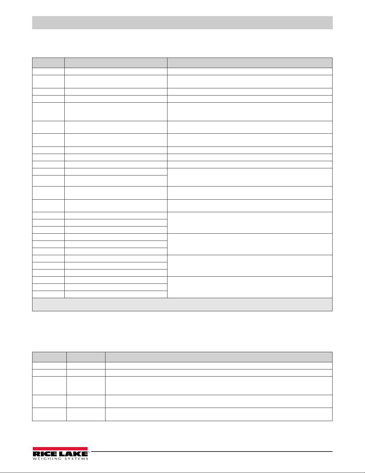
EDP Commands
7.14 Weigh Mode Commands
These commands function in the weigh mode. Non weight related commands work in setup mode.
Command Description Values
P Returns what the indicator is currently displaying -ZZ Returns what the indicator is currently displaying
along with the currently displayed annunciators
CONSNUM Returns current consecutive number value 0–9999999, 0 (default)
UID Sets the unit ID Up to 8 alphanumeric characters, 1 (default)
SD Sets or returns the current system date MMDDYY, DDMMYY, YYMMDD, or YYDDMM. Enter six-digit date using the
ST Sets or returns the current system time HHMM (enter using 24-hour format)
STS Sets or returns the current system time with
seconds
RS Resets system Soft reset; Used to reset indicator without resetting configuration to factory defaults
SX Starts all serial data streams -EX Stops all serial data streams -SX#p Starts serial data stream for port p OK or ??
EX#p Stops serial data stream for port p
S Returns a single stream frame from the displayed
scale using the currently configured stream format
SF#n Returns a single stream frame from scale n using
the currently configured stream format
XA#n Returns the accumulator value in displayed units nnnnnnnnn UU
XAP#n Returns the accumulator value in primary units
XAS#n Returns the accumulator value in secondary units
XG#n Returns the gross weight in displayed units nnnnnnnnn UU
XGP#n Returns the gross weight in primary units
XGS#n Returns the gross weight in secondary units
XN#n Returns the net weight in displayed units nnnnnnnnn UU
XNP#n Returns the net weight in primary units
XNS#n Returns the net weight in secondary units
XT#n Returns the tare weight in displayed units nnnnnnnnn UU
XTP#n Returns the tare weight in primary units
XTS#n Returns the tare weight in secondary units
For commands ending with #n, n is the scale number (1); For commands ending with #p, p is the port number (1-6): Ports 1 and 2 are the two RS-232 ports,
Port 3 is the RS-485/422 port, Port 4 is the USB device port, Port 5 is the TCP Server, Port 6 is the TCP Client
Table 7-14. Weigh Mode Commands
See Section 11.2 on page 76
year-month-day order specified for the DATEFMT parameter, using only the last two
digits of the year; The current system date is returned by only sending SD
The current system time is returned by only sending ST
HHMMSS (enter using 24-hour format)
The current system time is returned by only sending STS
An EX command sent while in setup mode does not take effect until the indicator is
returned to weigh mode
--
--
7.15 Batching Control Commands
The commands listed in Table 7-15 provide batching control through a communications port.
Command Description Values
BATSTART Batch Start
BATSTOP Batch Stop
BATPAUSE Batch Pause Pauses an active batch and turns off all digital outputs except those associated with Concurrent and Timer setpoints;
BATRESET Batch Reset Stops the program and resets the batch program to the first batch step; use the BATRESET command after making
BATSTATUS Batch Status Returns XYYY where X is S (if the batch is stopped), P (if the batch is paused), R (if the batch is running); and YYY
If the BATRUN digital input is active or not assigned, the BATSTART command can be used to start the batch program
Stops an active batch and turns off associated digital outputs; Requires a Batch Start to resume processing
processing is suspended until the indicator receives a Batch Start signal; pressing the BATSTRT digital input or
BATSTART serial command resumes the batch and re-energizes all digital outputs turned off by the Batch Pause
changes to the batch configuration
is the setpoint number the batch is currently on (1-8)
Table 7-15. Batching Control Commands
© Rice Lake Weighing Systems ● All Rights Reserved 63
Page 64
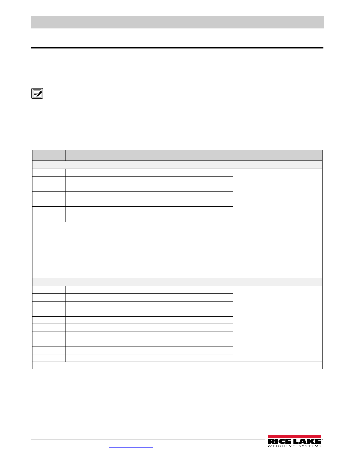
680 Synergy Plus
8.0 Print Formatting
The 680 provides multiple print formats, GFMT, NFMT, ACUMFMT, STPTFMT and HDRFMT, which determine the format of the
printed output when the
Each print format can be customized to include up to 1000 characters of information, such as company name and address, on
printed tickets. Use the print format menu through front panel of the indicator to customize the print formats.
NOTE: Press the down arrow to view the ASCII character decimal value on the second menu level.
See Section 11.9 on page 85 to view the ASCII character chart.
8.1 Print Formatting Tokens
Table 8-1 lists tokens which can be used to configure the print formats. Tokens included in the format strings must be enclosed
between < and > delimiters. Characters outside of the delimiters are printed as text on the ticket. Text characters can include
ASCII characters which can be printed by the output device.
Token Description Supported Ticket Formats
General Weight Data Tokens
<Gx> Gross weight, current scale GFMT, NFMT, ACUMFMT, STPTFMT
<Gx#n> Gross weight, scale n
<Nx> Net weight, current scale
<Nx#n> Net weight, scale n
<Tx> Tare weight, current scale
<Tx#n> Tare weight, scale n
<S> Current scale number
NOTE: For tokens with #n, n is the scale number (1). For tokens with an x, x is the character width of the weight field with padded spaces on
the left. If x is not specified, 10 is the assumed default for the weight field. x can be set using one or two digits and sets the minimum number
of characters in the weight field, but expands to show all characters for a value that has more characters than the minimum value set with x.
Example: To format a ticket to provide gross weight for Scale 1 with a minimum of 6 print characters, use the following token: <G6#1>
NOTE: Gross, net and tare weights can be printed in any configured weight unit by adding modifiers to the gross, net, and tare weight tokens:
/P (primary units), /D (displayed units) or /S (secondary units). If not specified, the currently displayed unit (/D) is assumed.
Example: To format a ticket to provide net weight in secondary units, use the following token: <N/S>
NOTE: Formatted weight strings default to contain a 10-digit weight field (including sign and decimal point), followed by a space and a 2-digit
unit identifier. Total field length with unit identifier is 13 characters. For tokens with an x, total field length with unit identifier is x + 3.
Accumulator Tokens
<A> Accumulated weight, current scale; Prints to 15 digits GFMT, NFMT, ACUMFMT
<A#n> Accumulated weight, scale n
<AA> Average accumulation, current scale
<AA#n> Average accumulation, scale n
<AC> Number of accumulations, current scale
<AC#n> Number of accumulations, scale n
<AT> Time of last accumulation, current scale
<AT#n> Time of last accumulation, scale n
<AD> Date of last accumulation, current scale
<AD#n> Date of last accumulation, scale n
NOTE: For tokens with #n, n is the scale number (1).
Print key is pressed. If a tare has been entered or acquired, NFMT is used; otherwise, GFMT is used.
Table 8-1. Print Format Tokens
64 Visit our website www.RiceLake.com
Page 65
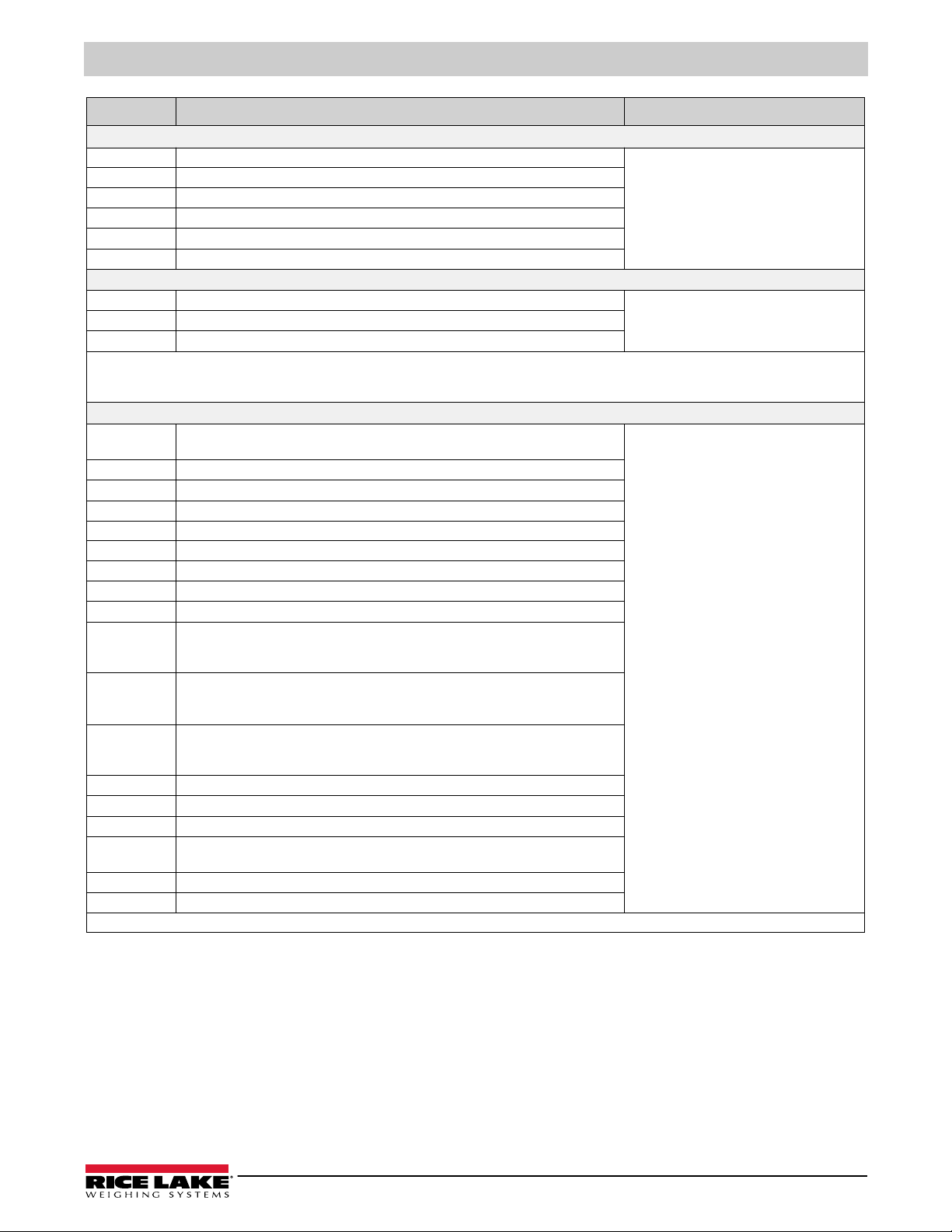
Print Formatting
Token Description Supported Ticket Formats
Setpoint Tokens
<SCV> Setpoint captured value STPTFMT
<SN> Setpoint number
<SNA> Setpoint name
<SPM> Setpoint mode (gross or net label)
<SPV> Setpoint preact value
<STV> Setpoint target value
Auditing Tokens
<CD> Last calibration date All
<NOC> Number of calibrations
<NOW> Number of weighments since last calibration
NOTE: Last calibration date (<CD>) and number of calibrations (<NOC>) are updated anytime a calibration is performed on any of the scales.
Number of weighments (<NOW> token) is incremented whenever the scale weight exceeds 10% of scale capacity. Scale must return to gross
or net zero before the value can be incremented again.
Formatting and General-Purpose Tokens
<nnn> ASCII character (nnn = decimal value of ASCII character); used for inserting control
<TI> Time
<DA> Date
<TD> Time and date
<UID> Unit ID number (up to 8 alphanumeric characters)
<CN> Consecutive number (up to 7 digits)
<H1> Insert header format 1 (HDRFMT1), see Table 8-2 on page 66
<H2> Insert header format 2 (HDRFMT2), see Table 8-2 on page 66
<COMP> Company name (up to 30 characters)
<COAR1>
<COAR2>
<COAR3>
<CONM1>
<CONM2>
<CONM3>
<COPH1>
<COPH2>
<COPH3>
<COML> Contact e-mail address (up to 30 characters)
<CR> Carriage return character
<LF> Line feed character
<NLnn> New line (nn = number of termination (<CR/LF> or <CR>)
<SPnn> Space (nn = number of spaces)*
<SU> Toggle weight data format (formatted/unformatted)
NOTE: If nn is not specified, 1 is assumed. Value must be in the range 1–99.
characters (STX, for example) in the print stream
Contact company address, lines 1–3 (up to 30 characters)
Contact names (up to 20 characters)
Contact phone numbers (up to 20 characters)
characters)*
All
Table 8-1. Print Format Tokens (Continued)
© Rice Lake Weighing Systems ● All Rights Reserved 65
Page 66
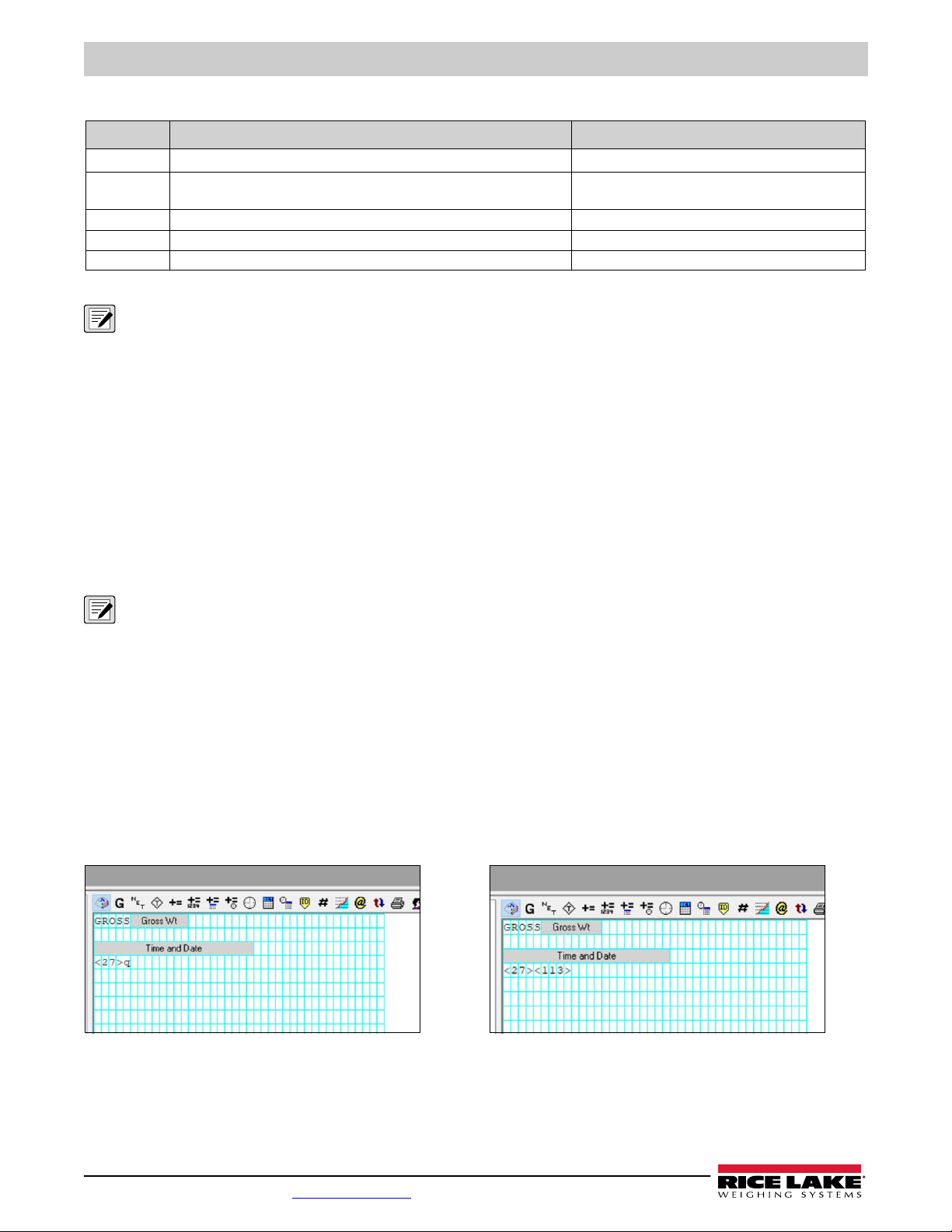
680 Synergy Plus
Table 8-2 lists the default 680 print formats:
Format Default Format String When Used
GFMT GROSS<G><NL2><TD><NL>
NFMT
ACUMFMT ACCUM <A><NL><DA> <TI><NL> Accumulator demand print format string
STPTFMT <SCV><SP><SPM><NL> Setpoint print operation with PSHPRNT=ON or WAITSS
HDRFMT1-2 COMPANY NAME<NL>STREET ADDRESS<NL>CITY ST ZIP<NL2>
NOTE: The 1000 character limit of each print format string includes the output field length of the print formatting tokens,
not the token length. For example, if the indicator is configured to display a decimal point, the <G> token generates an
output field of 13 characters: the 10 character weight value (including decimal point), one space, and a two-digit units
identifier. For tokens with an x (e.g. <Gx> or <Gx#n>), total field length with unit identifier is x + 3.
NOTE: PT (preset tare) is added to the tare weight if tare was keyed in.
GROSS<G><NL>TARE<SP><T><NL>NET<SP2><N>
<NL2><TD><NL>
Table 8-2. Default Print Formats
Weigh mode
Weigh mode
– no tare in system
– tare in system
8.2 Customizing Print Formats
The GFMT, NFMT, ACUMFMT, STPTFMT and HDRFMT formats can be customized using the print format menu (PForMT)
via the front panel. See Section 4.4.6 on page 44 for the print format menu structure. To access the print format menu the
indicator must be in setup mode (Section 4.1 on page 32).
Using the Front Panel
Use the print format menu to customize the print formats and to edit the print format strings by changing the ASCII characters in
the format string. See Section 3.3.2 on page 27 for the alphanumeric entry procedure to edit the print format string.
NOTE: Some characters cannot be displayed on the 680 front panel, see the ASCII character chart in Section 11.9 on
page 85 for available characters. The 680 can send or receive ASCII characters; the character printed depends on the
particular ASCII character set implemented for the receiving device.
8.3 Non-Human Readable Characters
ASCII characters 0 through 31 are non-human readable characters. Since these characters are not visible, they do not appear as selectable
options in a 680 print format. To include a special character in a print format, the decimal equivalent needs to be used. For example, the
special character Esc would be <27> or 60, 50, 55, 62 (less the commas).
Examples of a print release command for a TMU295 in the GROSS format:
Print Format:
GROSS<G><NL2><TD><NL><27>q
In Revolution:
Print Format:
GROSS<G><NL2><TD><NL><27><113>
In Revolution:
66 Visit our website www.RiceLake.com
Page 67
Setpoints
9.0 Setpoints
The 680 indicator provides eight configurable setpoints for control of both indicator and external equipment functions. Setpoints
can be configured to perform actions or functions based on specified parameter conditions. Parameters associated with various
setpoint kinds can, for example, be configured to perform functions (print, tare, accumulate), to change the state of a digital
output controlling indicator or external equipment functions, or to make conditional decisions.
NOTE: Weight-based setpoints are tripped by values specified in primary units only.
9.1 Batch and Continuous Setpoints
680 setpoints can be either continuous or batch.
Continuous setpoints are free-running; the indicator constantly monitors the condition of free-running setpoints at each A/D
update. The specified setpoint action or function is performed when the designated setpoint parameter conditions are met. A
digital output or function assigned to a free-running setpoint continuously changes state, becoming active or inactive, as
defined by the setpoint parameters.
Batch setpoints (BATCH = ON) which have digital outputs associated to them remain active until the setpoint condition is met.
The setpoint is then latched for the remainder of the batch sequence.
To use batch setpoints, set the batching (BATCHNG) parameter on the setpoints (SETPTS) menu. This parameter defines
whether a batch sequence is automatic or manual. AUTO sequences repeat continuously after receiving a single batch start
signal, while MANUAL sequences only run through once for each Batch Start signal. The batch start signal can be initiated by a
digital input (set to BATSTRT), or an EDP command (BATSTART).
For a setpoint to be used as part of a batch sequence, its batch sequence (BATCH) parameter must be set to ON. If a setpoint
is defined and enabled, but its Batch Sequence parameter is set to OFF, the setpoint operates as a continuous setpoint even
during batch sequences.
NOTE: In applications which contain both batch setpoint routines and continuous setpoints, it is good practice to keep
continuous setpoints separate from the batch sequence.
NOTE: Do not assign them the same digital output.
NOTE: Set the ACCESS parameter ON when creating and testing batch routines. Once the batching routine is complete and
ready for production, ACCESS can be set to OFF to prevent changes to the configured setpoint value, or to HIDE to prevent
changing or viewing the value.
Parameter Description Batch Continuous
OFF Off – Setpoint turned off/ignored
GROSS Gross Weight – Performs functions based on the gross weight; the target weight entered is
considered a positive gross weight
NET Net Weight – Performs functions based on the net weight; the target weight entered is
considered a positive net weight value
-GROSS Negative Gross Weight – Performs functions based on the gross weight; the target weight
entered is considered a negative gross weight
-NET Negative Net Weight – Performs functions based on the net weight; the target weight entered is
considered a negative net weight value
ACCUM Accumulate – Compares the value of the setpoint to the source scale accumulator; the
accumulator setpoint is satisfied when the value of the source scale accumulator meets the
value and conditions of the accumulator setpoint
POSREL Positive Relative – Performs functions based on a specified value above a referenced setpoint,
using the same weight mode as the referenced setpoint
NEGREL Negative Relative – Performs functions based on a specified value below a referenced setpoint,
using the same weight mode as the referenced setpoint
Table 9-1. Setpoint Kinds
© Rice Lake Weighing Systems ● All Rights Reserved 67
X X
X X
X X
X X
X X
X X
X X
Page 68
680 Synergy Plus
Parameter Description Batch Continuous
PCTREL Percent Relative – Performs functions based on a specified percentage of the target value of a
referenced setpoint, using the same weight mode as the referenced setpoint; the actual target
value of the Percent Relative setpoint is calculated as a percentage of the target value of the
referenced setpoint
PAUSE Pause – Pauses the batch sequence indefinitely; a Batch Start signal must be initiated to
continue the batch process
DELAY Delay – Delays the batch sequence for a specified time; the length of the delay (in tenths of a
second) is specified on the Value parameter
WAITSS Wait Standstill – Suspends the batch sequence until the scale is at standstill X
COUNTER Counter – Specifies the number of consecutive batch sequences to perform; place counter
setpoints at the beginning of a batch routine
AUTOJOG Auto-Jog – Automatically checks the previous weight-based setpoint to verify the setpoint weight
value is satisfied in a standstill condition
• If the previous setpoint is not satisfied when at standstill, the AUTOJOG setpoint activates
the digital output of the previous weight-based setpoint for a period of time, specified on
the Value parameter (in tenths of a second)
• The AUTOJOG process repeats until the previous weight-based setpoint is satisfied when
the scale is at standstill
NOTE: The AUTOJOG digital output is typically used to signify an AUTOJOG operation is
being performed.
NOTE: AUTOJOG uses the digital output of the previous weight-based setpoint, and
should not be assigned to the same digital output as the related weight-based setpoint.
COZ Center of Zero – Monitors for a gross center of zero condition
• The digital output associated with this setpoint kind is activated when the referenced scale
is at center of zero
• No value is required for this setpoint
INMOTON In-Motion – Monitors for an in-motion condition
• The digital output associated with this setpoint is activated when scale is not at standstill
• No value is required for this setpoint
INRANGE In-Range – Monitors for an in-range condition
• The digital output associated with this setpoint is activated when the scale is within
capacity range
• No value is required for this setpoint
TIMER Timer – Tracks the progress of a batch sequence based on a timer
• The timer value, in tenths of a second, determines the length of time allowed between start
and end setpoints
• Start and End parameters are used to specify the start and end setpoints
• If the End setpoint is not reached before the timer expires, the digital output associated
with this setpoint is activated
CONCUR Concurrent – Allows a digital output to remain active over a specified portion of the batch
sequence
• Type 1 (VALUE=0): The digital output associated with this setpoint becomes active when
the Start setpoint becomes the current batch step and remains active until the End setpoint
becomes the current batch step
• Type 2 (VALUE > 0): If a non-zero value is specified for the Value parameter, the value
represents the timer, in tenths of a second, for this setpoint; The digital output associated
with this setpoint becomes active when the Start setpoint becomes the current batch step
and remains active until the timer expires
TOD Time of Day – Performs functions when the internal clock time of the indicator matches the
specified setpoint time
ALWAYS Always – This setpoint is always satisfied; It is typically used to provide an endpoint for true/false
branching batch routines
NEVER Never – This setpoint is never satisfied
• Used to branch to a designated setpoint in true/false branching batch routines in which the
batch does not continue through the normal sequence of batch setpoints
X X
X
X
X
X
X X
X
X
Table 9-1. Setpoint Kinds (Continued)
X
X
X
X
X
68 Visit our website www.RiceLake.com
Page 69
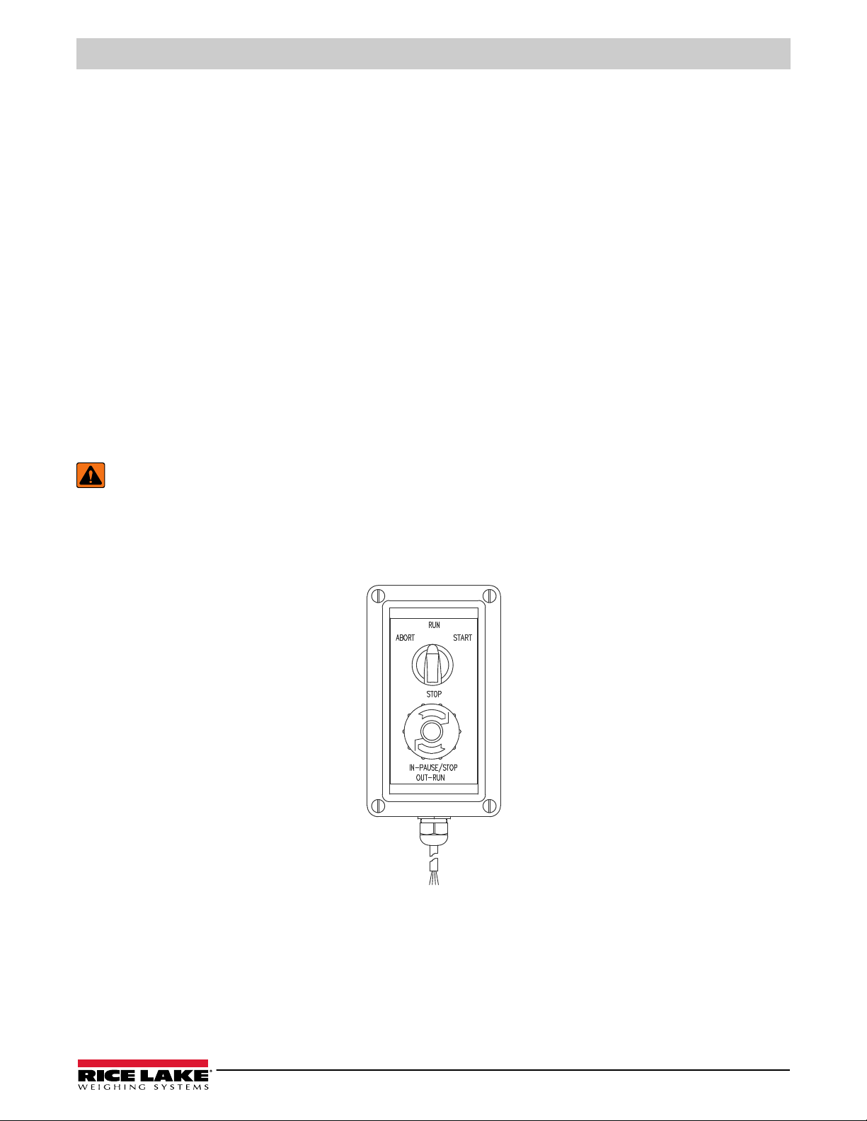
Setpoints
9.2 Batch Operations
Batches are controlled by digital inputs or EDP commands.
Batch Run (BATRUN digital input)
If a BATRUN digital input is configured, it must be active (low) for a batch to be started, and for it to continue to run. If a batch is
running and the input becomes inactive (high), it will stop the batch at the current batch setpoint and turn off all associated
digital outputs.
Batch Start (BATSTRT digital input or BATSTART EDP command)
If the BATRUN digital input is active (low), or is not assigned, batch start will start a batch, resume a paused batch or resume a
stopped batch. If the BATRUN digital input is inactive (high), batch start will reset the current batch.
Batch Pause (BATPAUS digital input or BATPAUSE EDP command)
The BATPAUS digital input will pause an active batch, turning off all associated digital outputs EXCEPT those associated with
CONCUR and TIMER setpoints, while the input is active (low). As soon as the BATPAUS digital input is made inactive (high),
the batch will resume.
BATPAUSE EDP command works the same, except the batch will not resume until a batch start signal is received.
Batch Stop (BATSTOP digital input or BATSTOP EDP command)
Stops an active batch at the current setpoint and turns off all associated digital outputs.
Batch Reset (BATRESE digital input or BATRESET EDP command)
Stops and resets an active batch to the beginning of the process.
WARNING: To prevent personal injury and equipment damage, software-based interrupts must always be supplemented by
emergency stop switches and other safety devices necessary for the application.
9.3 Batching Switch
The batching switch option (PN 19369) comes as a complete unit in an FRP enclosure, with legend plate, emergency stop, and
a run/start/abort three-way switch.
Figure 9-1. Batching Switch
Both switches are wired into the indicator’s digital I/O terminal as shown in Figure 9-2 on page 70. Each switch uses a separate
digital input. Digital input BIT 1 must be set to BATSTRT and BIT 2 must be set to BATRUN.
Once cables and switches have been connected to the indicator, use the setup switch to place the indicator in setup mode. Use
the Digital I/O menu (Section 4.4.9 on page 49) to configure digital input and output functions.
© Rice Lake Weighing Systems ● All Rights Reserved 69
Page 70
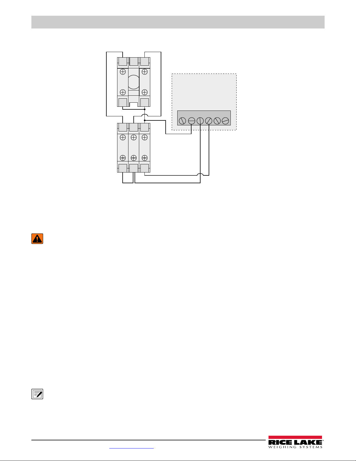
680 Synergy Plus
RED
WHITE
BLACK
RED
BLACK
A
B
O
R
T
S
T
A
R
T
3
4
1
2
NO NC NC
NO NO
+5V
GND
DIO1
DIO2
DIO3
DIO4
DIGITAL I/O
CPU BOARD
3
4
1
2
3
4
GREEN
DIO1 = BATSTRT (RED)
DIO2 = BATRUN (WHITE)
ABORT/START SWITCH
EMERGENCY STOP SWITCH
Figure 9-2. Batching Switch and Wiring Diagram Example
When configuration is complete, exit setup mode. Initialize the batch by turning the three-way switch to ABORT, then unlock the
STOP button (the STOP button must be in the OUT position to allow the batch process to run). The batching switch is now
ready to use.
WARNING: If no digital input is assigned to Batch Run, batching proceeds as if Batch Run were always on (the batch starts
when the three-way switch is turned to Run, but the Stop button does not function).
To begin a batch process, turn the three-way switch to START momentarily. If the STOP button is pushed during the batch
process, the process halts and the button locks in the IN position.
The START switch is ignored while the STOP button is locked in the IN position. The STOP button must be turned
counterclockwise to unlock it, then released into the OUT position to enable the three-way switch.
To restart an interrupted batch from the step where it left off:
1. Unlock STOP button (OUT position).
2. Turn three-way switch to START.
To restart an interrupted batch from the first batch step:
1. Turn three-way switch to ABORT.
2. Unlock STOP button (OUT position).
3. Turn three-way switch to START.
To abort an interrupted batch:
1. Push the STOP button.
2. Turn three-way switch to ABORT.
3. Unlock STOP button (OUT position). A new batch can now be started.
NOTE: Use this procedure (or the BATRESET serial command) to initialize the new batch routine following any change to
the setpoint configuration.
70 Visit our website www.RiceLake.com
Page 71

Setpoints
9.4 Batching Examples
9.4.1 Example 1
The following example uses seven setpoints to dispense material from a hopper in 100 lb batches and to automatically refill the
hopper when its weight drops below 300 lb.
Bits 1 and 2 in the Digital I/O menu (Section 4.4.9 on page 49) are assigned to batch start and batch run functions: BATRUN
must be on (low) before the BATSTRT input starts the batch.
SLOT 0, BIT 1=BATSTRT
SLOT 0, BIT 2=BATRUN
BATCHNG=MANUAL
Setpoint 1 ensures the hopper has enough material to start the batch. If the hopper weight is 300 lb or higher, setpoint 1 is
tripped.
SETPT 1 TRIP=HIGHER
KIND=GROSS ALARM=ON
VALUE=300 BATCH=ON
Setpoint 2 waits for standstill, then performs a tare to put the indicator into net mode.
SETPT 2
KIND=WAITSS
PSHTARE=ON
Setpoint 3 is used as a reference (relative setpoint) for setpoint 4.
SETPT 3 TRIP=HIGHER
KIND=NET BATCH=OFF
VALUE=0
Setpoint 4 is used to dispense material from the hopper. When the hopper weight falls to 100 lb less than its weight at the
relative setpoint (setpoint 3), digital output 1 is set off.
SETPT 4 DIG OUT=1
KIND=NEGREL BATCH=ON
VALUE=100 RELNUM=3
TRIP=LOWER
Setpoint 5 is used to evaluate the gross amount of material in the hopper after dispensing, and to maintain a minimum material
level in the hopper. When the hopper weight falls below 300 lb, digital output 2 becomes active and the hopper is refilled to
1000 lb.
SETPT 5 HYSTERS=700
KIND=GROSS DIG OUT=2
VALUE=300 BATCH=ON
TRIP=HIGHER
Setpoint 6 is used to ensure the operation performed in setpoint 4 is completed within 10 seconds. The START and END
parameters identify the setpoints monitored by the timer. If the timer expires before setpoint 5 starts, digital output 4 is turned on
as an alarm to signal a process fault.
SETPT 6 START=4
KIND=TIMER END=5
VALUE=100 DIG OUT=4
© Rice Lake Weighing Systems ● All Rights Reserved 71
Page 72

680 Synergy Plus
9.4.2 Example 2
The following example uses six setpoints to control a two-speed fill operation where both fast and slow feeds are on
simultaneously.
Bits 1 and 2 in the Digital I/O menu (Section 4.4.9 on page 49) are assigned to batch start and batch run functions: BATRUN
must be on (low) before the BATSTRT input starts the batch.
SLOT 0, BIT 1=BATSTRT
SLOT 0, BIT 2=BATRUN
BATCHNG=MANUAL
Setpoint 1 ensures the scale is empty (0±2 lb).
SETPT 1 TRIP=INBAND
KIND=GROSS BANDVAL=2
VALUE=0 BATCH=ON
Setpoint 2 checks for the weight of a container (>5 lb) placed on the scale.
SETPT 2 TRIP=HIGHER
KIND=GROSS BATCH=ON
VALUE=5
Setpoint 3 waits for standstill, then tares the container weight, placing the indicator in net mode.
SETPT 3
KIND=WAITSS
PSHTARE=ON
Setpoint 4 starts the fast fill operation. When the net weight reaches 175 lb, the setpoint trips and digital output 1 is set off.
SETPT 4 TRIP=HIGHER
KIND=NET DIG OUT=1
VALUE=175 BATCH=ON
Setpoint 5 controls the slow fill operation. When the net weight reaches 200 lb, the slow fill is stopped, the indicator waits for
standstill and performs a push print operation using the SPFMT ticket format.
SETPT 5 PSHPRNT=WAITSS
KIND=NET DIG OUT=2
VALUE=200 BATCH=ON
TRIP=HIGHER
Setpoint 6 is a continuous setpoint, used to allow the slow feed output to be on at the same time as the fast fill. The slow fill
output (digital output 2) is turned on when setpoint 4 (fast fill) starts and remains on until setpoint 5 begins.
SETPT 6 START=4
KIND=CONCUR END=5
VALUE=0 DIG OUT=2
72 Visit our website www.RiceLake.com
Page 73
Maintenance
10.0 Maintenance
The maintenance information in this manual is designed to cover aspects of maintaining and troubleshooting the 680 indicator.
Contact the local Rice Lake Weighing Systems dealer if a problem requires technical assistance.
NOTE: Have the scale model number and serial number available when calling for assistance.
10.1 Maintenance Checkpoints
The scale must be checked frequently to determine when a calibration is required. It is recommended a zero calibration be
checked every other day and a calibration checked every week for several months after installation. Observe the results and
change the period between calibration checks, depending upon the accuracy desired.
NOTE: Establish a routine inspection procedure. Report changes in the scale function to the individual or department
responsible for the scales’ performance.
10.2 Field Wiring
If a problem with the wiring is suspected, check the electrical portion of the scale.
• Check for proper interconnections between the components of the system
• Check wiring meets all specifications in the installation drawings
• Check all wiring and connections for continuity, shorts and grounds using an ohmmeter with the scale off
• Check for loose connections, poor solder joints, shorted or broken wires and unspecified grounds in wiring; these issues
cause erratic readings and shifts in weight readings
• Check all cable shields to ensure grounding is made at only the locations specified in the installation drawings
10.3 Troubleshooting Tips
Table 10-1 lists general troubleshooting tips for hardware and software error conditions
Symptom Possible Cause Remedy
680 does not power up Bad power supply Check power supply; Check presence of AC or DC power – breaker tripped or unit
unplugged; Power supply outputs around 12 VDC – replace if bad
Battery backed corrupt error message at
startup
vvvvvvv
or
vvvvvvv
Cannot enter setup mode Bad switch Test switch
Serial port not responding Configuration error Ensure port TRIGGER parameter is set to CMD for command input
A/D scale out of range Scale operation
Option card failure Possible defective card
Dead battery Perform configuration reset then check for low battery warning on display;
If battery is low, replace battery, perform another configuration reset, then reload
files/configuration
Over or under range scale
condition
Load cell connection
Bad load cell
or slot
Table 10-1. Basic Troubleshooting
Check scale; For out-of -range conditions in total scale display, check all scale
inputs for positive weight values
Check source scale for proper mechanical operation
Check load cell and cable connection
Check 680 operation with load cell simulator
Check status of sense settings
Disconnect power, remove and reinstall card in slot, then apply power again
© Rice Lake Weighing Systems ● All Rights Reserved 73
Page 74
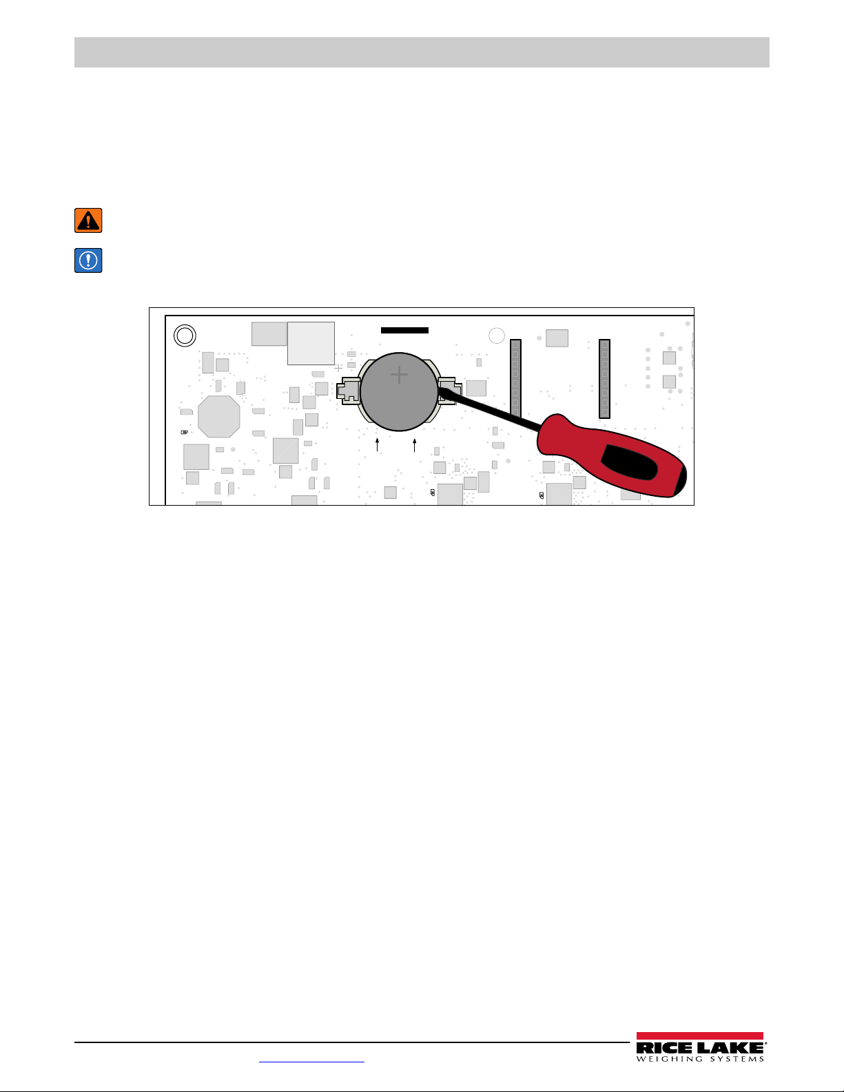
680 Synergy Plus
ASSY
PN/Rev
RICE LAKE
INSERT
SIDE UP
+
CR2032CR2032
LED3
LED1
LED2
10.4 Battery Replacement
The battery life varies depending on use. It is recommended to replace the battery every three years, or sooner, if left powered
off for extended periods of time to prevent data loss in the event of a power failure.
Use the Revolution configuration utility (Section 6.0 on page 54) or EDP commands (Section 7.0 on page 55) to store a copy of
the 680 configuration on a PC before attempting battery replacement. The 680 configuration can be restored from the PC if data
is lost.
WARNING: Risk of explosion if battery is replaced with an incorrect type. Dispose of used batteries according to federal,
state and local regulations.
IMPORTANT: Use anti-static protection for grounding and to protect components from electrostatic discharge (ESD) when
working inside the 680 enclosure. Procedures requiring work inside the 680 must be performed by qualified service
personnel only.
Figure 10-1. Non-Conductive Screw Driver Placement
To replace the battery, use the following procedure:
1. Disconnect power to the indicator.
2. Remove backplate as described in Section 2.4 on page 11.
3. Place the tip of a non-conductive flat head screw driver between negative contact and battery.
4. Twist screw driver to release battery from holder.
5. Press new replacement battery straight into the battery holder with the positive side up. See Section 2.10 on page 21
for replacement battery details.
74 Visit our website www.RiceLake.com
Page 75
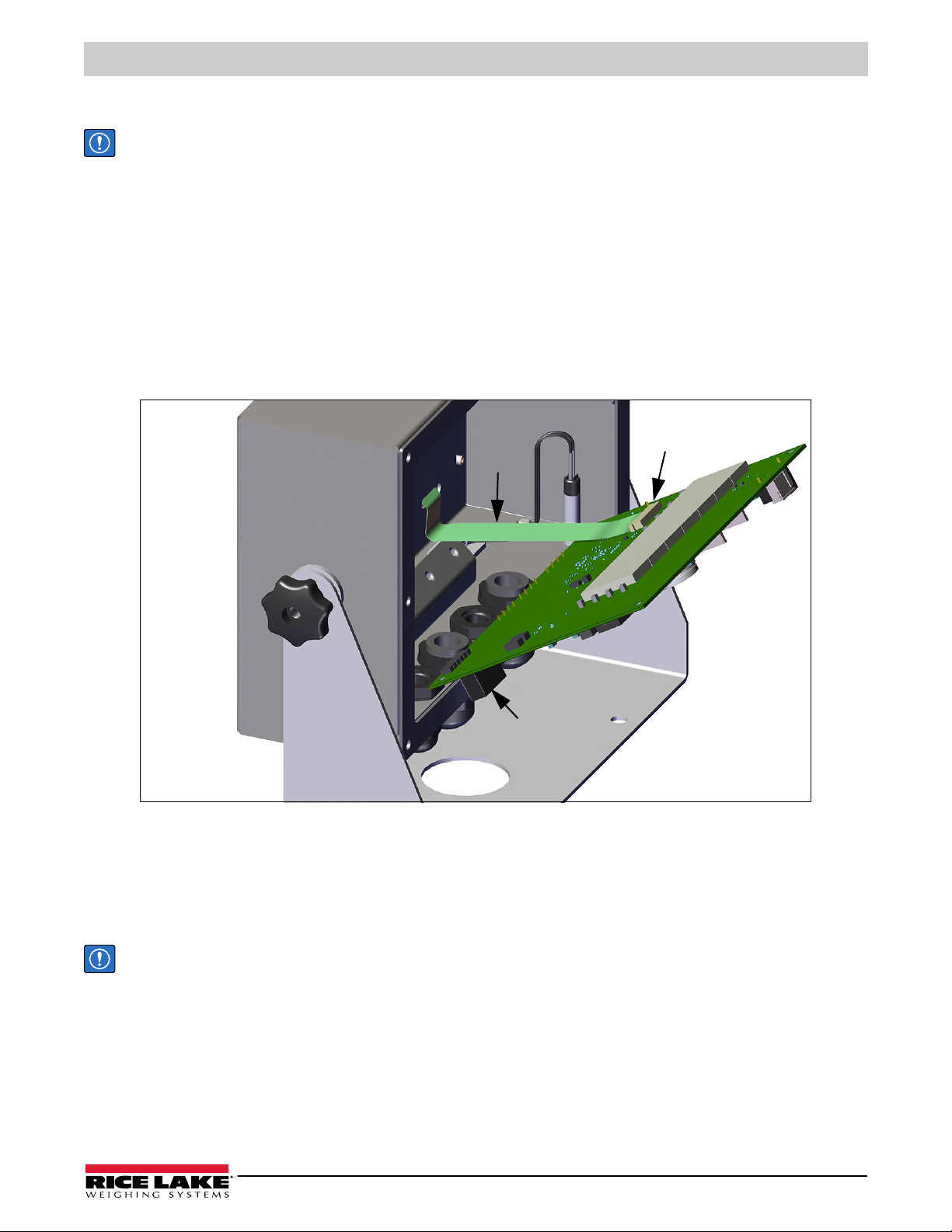
Maintenance
10.5 Board Replacement
IMPORTANT: Use anti-static protection for grounding and to protect components from electrostatic discharge (ESD) when
working inside the 680 enclosure. Procedures requiring work inside the 680 must be performed by qualified service
personnel only.
To replace a 680 board, use the following procedure:
1. Disconnect power to the indicator.
2. Remove backplate as described in Section 2.4 on page 11.
3. Label connections for re-installation to board.
4. Disconnect all connections from the board.
5. Remove the four corner screws securing the board.
6. Disconnect the overlay ribbon from the J26 connector on the reverse side of the board as it is lifted from the enclosure.
7. Use the J1-J5 connectors of the new replacement board to rest the board on the bottom edge of the enclosure opening.
Overlay
Ribbon
J1 Connector
Figure 10-2. Replacement Board Installation
J26 Connector
8. Press the end of the overlay ribbon up against the J26 connector while it is still closed. Open the J26 connector and
then close it once the end of the overlay ribbon has seated itself inside of the connector.
9. Place the new replacement board into the enclosure and secure with previously removed screws.
10. Reconnect all connections to the board. See Section 2.6 on page 18 for details on the board connectors.
IMPORTANT: Always verify indicator has been returned back to a safe state with the proper installation of all connections
and a complete functions test before reinstalling the backplate and returning the indicator back to service.
© Rice Lake Weighing Systems ● All Rights Reserved 75
Page 76
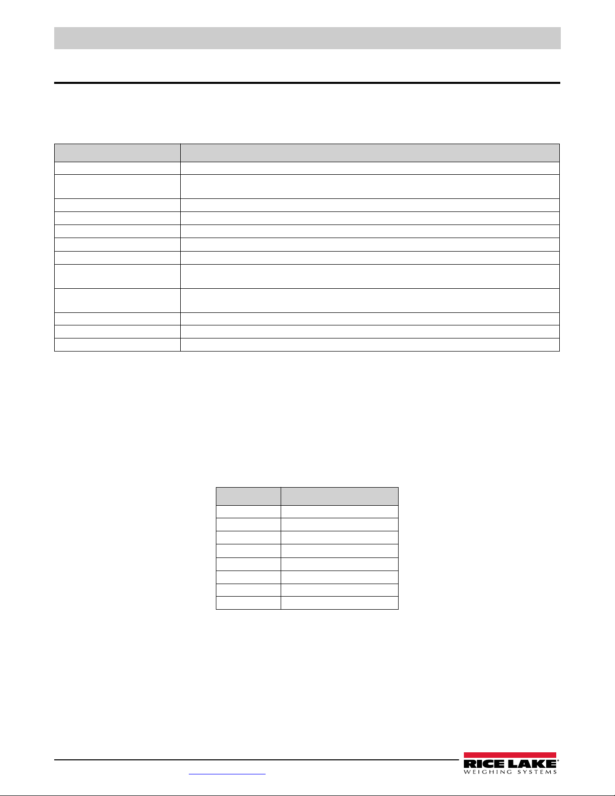
680 Synergy Plus
11.0 Appendix
11.1 Error Messages
The 680 indicator provides a number of error messages. When an error occurs, the message displays on the indicator to assist
in problem diagnosis. Table 11-1 lists these messages and their meanings.
Error Message Description
------- Overflow error – Weight value too large to be displayed
vvvvvvv
vvvvvvv Gross < underload limit – Gross value exceeds underload limit
battery low Scrolls across display every 30 seconds when battery is low
tare in motion not allowed Scrolls across display when attempting to perform a tare while weight is in motion, if in motion tares are not allowed
negative tare not allowed Scrolls across display when attempting to perform a negative tare, if a negative tare is not allowed
keyed tare not allowed Scrolls across display when attempting to perform a keyed tare, if a keyed tare is not allowed
tare larger than capacity
not allowed
tare already in system Scrolls across display when attempting to perform a tare if a tare is already in the system, if tare is not configured to
initial zero failed Scrolls across display when an attempt to perform an initial zero fails, only possible at startup
please wait Scrolls across display when calibrating
alarm Displays when a configured setpoint’s ALARM action occurs
Gross > overload limit –
be caused by input signal > 45 mV or common mode voltage > 950 mV
Scrolls across display when attempting to perform a tare larger than capacity, if it is not allowed
replace or remove
Gross value exceeds overload limit; Check configuration or signal input level; Overload can
Table 11-1. 680 Error Messages
11.2 ZZ EDP Command
The ZZ EDP command can be used to remotely query the value currently displayed on the 7-digit display, along with the units
and a number representing the current state of the eight LED annunciators. The number represents the LED annunciators
currently lit (Table 11-2).
Example:
If the ZZ command returns: “2500 LB 145”, that means the weight on the display is 2500 pounds and the gross,
standstill and lb annunciators are lit. The number 145 represents the sum of the values for the gross mode annunciator
(16), the standstill annunciator (128) and the lb annunciator (1).
Decimal Value Annunciator
1 lb/primary units
2 kg/secondary units
4 Tare entered
8 Keyed tare entered
16 Gross
32 Net
64 Center of zero
128 Standstill
Table 11-2. Status Codes Returned on the ZZ Command
76 Visit our website www.RiceLake.com
Page 77
Appendix
<STX> <POL> <wwwwwww> <UNIT> <G/N> <S> <TERM>
ASCII 002
Polarity:
<space> = Positive
<–> = Negative
Weight: 7 digits, right-justied, dummy
zeroes, decimal point with no leading
zeroes except for leading zero immediately
preceding the decimal point. Leading
zeroes transmitted as spaces.
L = pounds
K = kilograms
T = tons
G = grams
O = ounces
G = Gross
N = Net
Status:
<space> = valid
I = Invalid
M = Motion
O = Over/under range
Z = COZ
<CR> <LF>
or <CR>
Carriage
Return
Polarity:
<+> for positive
"–" for negative
Six digits, right justified, floating decimal
(follows weight if not embeded),
leading zeroes are present.
g for Gross
n for Net
Hex value of <03>
is entered in string
lb = pound
kg = kilogram
g = gram
tn = ton (short)
t = ton (metric)
oz = ounce
<space> = none
Space
Character
<CR> <POL> <wwwwww> <S> <SP> <UNIT> <SP> <G/N> <SP> <SP> <ETX>
Space character
(2)
Space
Character
Status:
<space> = valid or invalid
m = motion
o = over/under range
11.3 Continuous Data (Stream) Output Formats
When the trigger setting for a port is set to STRIND or STRLFT, data is continuously streamed from the appropriate port in one
of the four fixed format options or a custom format option.
Rice Lake Weighing Systems Stream Format (RLWS)
Figure 11-1. Rice Lake Weighing Systems Stream Data Format
Cardinal Stream Format (cardnal)
Figure 11-2. Cardinal Stream Data Format
© Rice Lake Weighing Systems ● All Rights Reserved 77
Page 78
680 Synergy Plus
Space
Polarity:
<+> for positive
"–" for negative
Six digits, right justified, floating decimal,
leading zeros are present
g for Gross
n for Net
<CR><LF>
or
<CR>
lb = pound
kg = kilogram
g = gram
tn = ton (short)
t = ton (metric)
oz = ounce
<space> = none
Space
<SP> <G/N> <POL> <wwwwww> <SP> <UNIT> <TERM>
<STX> <SWA> <SWB> <SWC> <wwwwww> <tttttt> <CR>
ASCII 002
Status Word A
<CR> entered at end
of string.
Status Word B
Status Word C
MUL1 MUL0Parity
DP2 DP1 DP0 Fixed Zero/Dec. Pt. Location
0 0 0 x 100 (2 xed zeroes)
0 0 1 x 10 (1 xed zero)
0 1 0 x 1 (No decimal point)
0 1 1 x 0.1 (1 decimal place)
1 0 0 x 0.01 (2 decimal places)
1 0 1 x 0.001 (3 decimal places)
1 1 0 x 0.0001 (4 decimal places)
1 1 1 x 0.00001 (5 decimal places)
Disp. Div.
MUL1
MUL0
M ultiplier
0 1 x 1
1 0 x 2
1 1 x 5
Even parity bit.
Requires EDP Port setup.
Status Word A:
Status Word C: ASCII 20h (space)
Even parity bit:
Requires EDP Port setup.
Status Word B:
0 = Gross Display Mode
1 = Net Display Mode
0 = Positive indicated weight value
1 = Negative indicated weight value
0 = In range
1 = Out of range
0 = Stable
1 = Motion
0 = lb
1 = kg
Even parity bit:
Requires EDP Port
setup.
Six digits, right justied, dummy zeros, decimal
point with no leading zeroes except for immediately
preceding the decimal point. Leading zeroes
transmitted as spaces.
Tare Weight: Six digits, right justied,
dummy zeros, decimal point with no
leading zeroes except for immediately
preceding the decimal point.
Leading zeroes transmitted as spaces.
76543210
DP2 DP1 DP010
Parity
76543210
1000000
Parity
76543210
10
Avery Weigh-Tronix Stream Format (wtronix)
Figure 11-3. Avery Weigh-Tronix Stream Data Format
Mettler Toledo Stream Format (toledo)
78 Visit our website www.RiceLake.com
Figure 11-4. Mettler Toledo Stream Data Format
Page 79
Appendix
Minebea Stream Format (Minebea)
Data Output Format with 16 Characters (without Data Header) - Normal Operation
Position 1 2 3 4 5 6 7 8 9 10 11 12 13 14 15 16
+ * D D D D D D D D * U U U CR LF
or - * D D D D D D D D * U U U CR LF
or * * * * * * * * * * * * * * CR LR
Plus or minus sign
+/-
Space
*
Digit or Leter (max. 7 characters plus decimal point)
D
Unit symbol (1 to 3 letters followed by 2-0 spaces)
U
Carriage return
CR
Line feed
LF
Table 11-3. Minebea Stream Data Format
11.4 Custom Stream Formatting
The custom stream format (custom) can be configured in the stream format menu (sformt) via the front panel. See
Section 4.4.7 on page 45 for the stream format menu structure. The indicator must be in setup mode (Section 4.1 on page 32)
to access the stream format menu.
Using the Front Panel
Use the stream format menu to customize the custom stream format by changing the ASCII characters in the format string.
SETUP ▼to CONFIG ►to SFORMT ▼to SFORMAT (set to CUSTOM) ►to CUSTOM ▼to format string entry
See Section 3.3.2 on page 27 for the alphanumeric entry procedure to edit the format string.
NOTE: The 680 can send or receive ASCII characters; the character printed depends on the particular ASCII character set
implemented for the receiving device. Some characters cannot be displayed on the 680 front panel, see the ASCII character
chart in Section 11.9 on page 85 for available characters and see Section 8.3 on page 66 for a description of Non-Human
Readable Characters.
For example, enter the following string of format tokens to recreate the standard RLWS stream format as a custom stream
format: <2><P><W7.><U><M><S><CR><LF>
<2> Sends ASCII character 2, or STX.
<P> Sends the Polarity character.
<W7.> Sends 7 weight digits, no leading zeros, with a floating decimal point as needed.
<U> Sends the Units.
<M> Sends the Mode.
<S> Sends the Status.
<CR> Sends a Carriage Return.
<LF> Sends a Line Feed.
© Rice Lake Weighing Systems ● All Rights Reserved 79
Page 80
680 Synergy Plus
Custom Stream Format Tokens
Format Token Defined By Description
<P[G | N | T]> STRM.POS#n
STRM.NEG#n
<U[P | S]> STRM.PRI#n
STRM.SEC#n
<M[G | N | T]> STRM.GROSS#n
STRM.NET#n
STRM.TARE#n
<S> STRM.MOTION#n
STRM.RANGE#n
STRM.OK#n
STRM.INVALID#n
STRM.ZERO#n
<UID> UID Unit ID number – specifies the unit identification number as an alphanumeric value up to 8 characters long
<###> -- To send an ASCII character; ### is a number 0 to 255; for example: <2> sends the ASCII character 2, Start
XXXX -- To send literal characters; XXXX represents literal characters to include in the string by not including < >;
<B [–]n,…> See descriptions below Bit fields. Comma-separated sequence of bit field specifiers; must be exactly 8-bits;
B0 -- Always 0
B1 -- Always 1
B2 Configuration =1 if even parity
B3 Dynamic =1 if MODE=NET
B4 Dynamic =1 if COZ
B5 Dynamic =1 if standstill
B6 Dynamic =1 if gross negative
B7 Dynamic =1 if out of range
B8 Dynamic =1 if secondary
B9 Dynamic =1 if tare in system
B10 Dynamic =1 if tare is keyed
B11 Dynamic =00 if MODE=GROSS
B12 Dynamic =00 if UNITS=PRIMARY
B13 Configuration =00 (not used)
B14 Configuration =00 (not used)
B15 Configuration =00 (not used)
B17 Configuration =000 if current DECPNT=8888800 =100 if current DECPNT=88888.88
Polarity – specifies positive or negative polarity for the current or specified (Gross/Net/Tare) weight on the
source scale. Possible values are SPACE, NONE, + (for STR.POS#n) or – (for STR.NEG#n)
Units – specifies primary or secondary units for the current or specified weight on the source scale
Mode – specifies gross, net or tare weight for the current or specified weight on the source scale
Status for the source scale – default values and meanings for each status:
• STR.MOTION#n M In motion
• STR.RANGE#n O Out of range
• STR.OK#n <space> OK
• STR.INVALID#n I Invalid
• STR.ZERO#n Z COZ
of Text (STX) and the token <13> sends a Carriage Return
for example: SCALE<W7.><U><CR><LF> will stream “SCALE 1234 L” with a weight of 1234 pounds
minus sign ([–]) inverts the bit
=01 if MODE=NET
=10 if MODE=TARE
=11 (not used)
=01 if UNITS=SECONDARY
=11 (not used)
=01 if current DSPDIV=1
=10 if current DSPDIV=2
=11 if current DSPDIV=5
=01 if primary DSPDIV=1
=10 if primary DSPDIV=2
=11 if primary DSPDIV=5
=01 if secondary DSPDIV=1
=10 if secondary DSPDIV=2
=11 if secondary DSPDIV=5
=001 if current DECPNT=8888880 =101 if current DECPNT=8888.888
=010 if current DECPNT=8888888 =110 if current DECPNT=888.8888
=011 if current DECPNT=888888.8 =111 if current DECPNT=88.88888
Table 11-4. Custom Stream Format Tokens
80 Visit our website www.RiceLake.com
Page 81
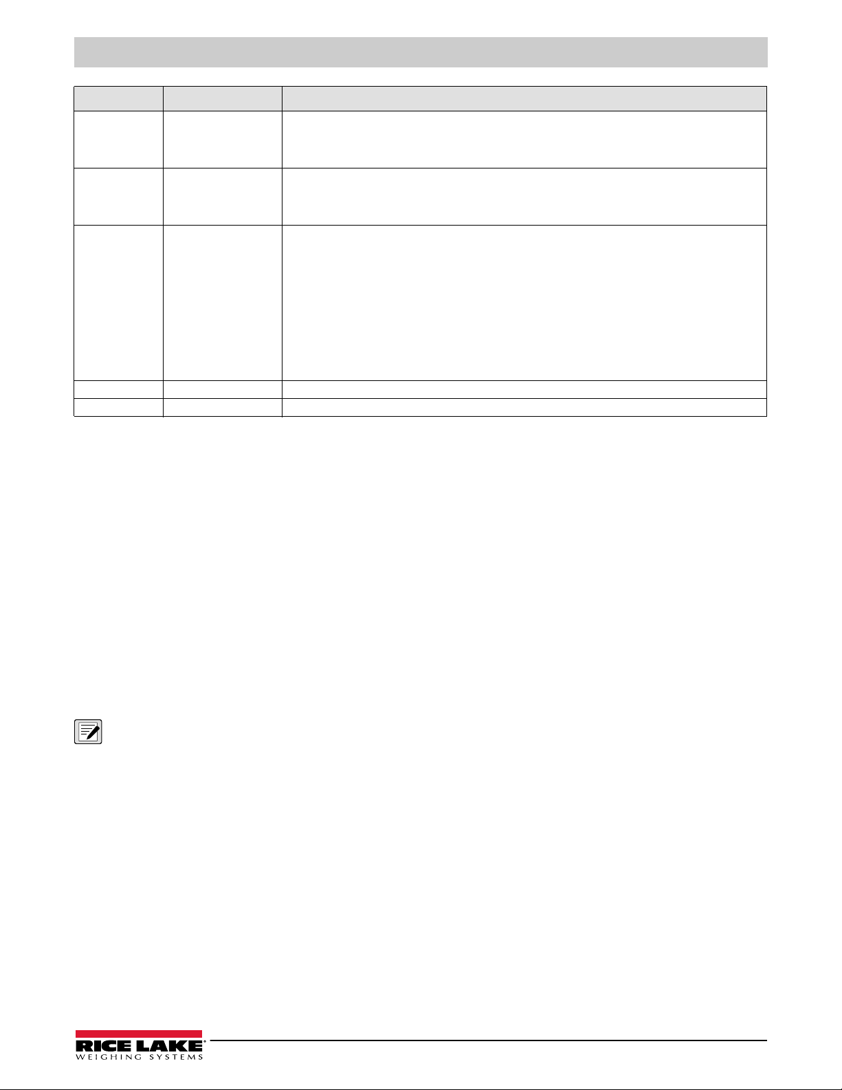
Format Token Defined By Description
B18 Configuration =000 if primary DECPNT=8888800 =100 if primary DECPNT=88888.88
B19 Configuration =000 if secondary DECPNT=8888800 =100 if secondary DECPNT=88888.88
<wspec [–] [0] digit
[.[.][digit]]>
<CR> -- Carriage return
<LF> -- Line feed
Scale weight Weight for the source scale. wspec is defined as follows:
=001 if primary DECPNT=8888880 =101 if primary DECPNT=8888.888
=010 if primary DECPNT=8888888 =110 if primary DECPNT=888.8888
=011 if primary DECPNT=888888.8 =111 if primary DECPNT=88.88888
=001 if secondary DECPNT=8888880 =101 if secondary DECPNT=8888.888
=010 if secondary DECPNT=8888888 =110 if secondary DECPNT=888.8888
=011 if secondary DECPNT=888888.8 =111 if secondary DECPNT=88.88888
wspec indicates whether the weight is the current displayed weight (W, w), gross (G, g), net (N, n) or tare
(T, t) weight; upper-case letters specify right-justified weights, lower-case are left-justified
Optional /P or /S suffixes can be added before the ending delimiter (>) to specify weight display in
primary (/P) or secondary (/S) units
[–] Enter a minus sign (–) to include sign for negative values
[0] Enter a zero (0) to display leading zeros
digit[.[.][digit]] The first digit indicates the field width in characters; the decimal point only indicates a
floating decimal; a decimal point with a following digit indicates fixed decimal with n digits to the right
of the decimal; two consecutive decimals send the decimal point even if it falls at the end of the
transmitted weight field
Table 11-4. Custom Stream Format Tokens (Continued)
Appendix
11.5 Audit Trail Support
Audit trail support provides tracking information for configuration and calibration events. To prevent potential misuse, all
configuration and calibration changes are counted as change events.
Audit trail information can be printed from Revolution or by sending the DUMPAUDIT serial command. Revolution can be used
to display audit trail information. The audit trail display includes the legally relevant (LR) version number (firmware version for
the code which provides audit trail information), a calibration count and a configuration count.
See Section 3.4.10 on page 29 for steps to view the Audit Trail counters.
11.6 Conversion Factors for Secondary Units
The 680 has the capability to mathematically convert a weight into many different types of units and instantly display those
results with a press of the
Units key.
Secondary units can be specified on the Format menu using the SECNDR parameter.
NOTE: Multipliers are preconfigured within the indicator.
Ensure the secondary decimal point position is set appropriately for the scale capacity in the secondary units.
11.7 Digital Filtering
Digital filtering is used to create a stable scale reading in challenging environments. The 680 allows selection of Digital Rolling
Average Filtering (
None (RAW) for no filtering. See
The scale’s sample rate effects all types of filtering. The A/D sample rate is selected by the SMPRAT scale parameter. The A/D
sample rate is the number of weight readings the indicator takes per second (SMPRAT). This can be 6.25, 7.5, 12.5, 15, 25, 30,
50, 60 or 120 hertz (readings per second). Set the A/D sample rate to the lowest setting required for the application. Lower
settings result in better stability.
Section 11.7.1
), Adaptive Filtering (
Section 4.4.1 on page 34
Section 11.7.2 on page 82
), Damping (
Section 11.7.3 on page 83
) or
for configuration menu layout and the location of FLTRCHN parameter.
11.7.1 Digital Rolling Average Filter (AVGONLY)
The digital rolling average filter uses mathematical averaging with three stages. These configurable stages control the effect of
a single A/D reading on the displayed weight. When an A/D reading outside of a predetermined band is encountered, the digital
rolling average filter is overridden and the display jumps directly to the new value.
© Rice Lake Weighing Systems ● All Rights Reserved 81
Page 82

680 Synergy Plus
Digital Filter Stages (DGFLTR1-3)
The filter stages can each be set to a value of 1–256. The value assigned to each stage sets the number of readings received
from the preceding filter stage before averaging. Setting the filter stages to 1 effectively disables the rolling filter.
A rolling average is passed to successive filtering stages for an overall filtering effect which is effectively a weighted average of
the product of the values assigned to the filter stages (DGFLTR1 x DGFLTR2 x DGFLTR3) within a time frame corresponding to
the sum of the values (DGFLTR1 + DGFLTR2 + DGFLTR3).
Digital Filter Sensitivity (DFSENS) and Threshold (DFTHRH)
The rolling averaging filter can be used by itself to eliminate vibration effects, but heavy filtering also increases settling time.
The DFSENS and DFTHRH parameters can be used to temporarily override filter averaging and improve settling time.
• DFSENS specifies the number of consecutive A/D readings which must fall outside the filter threshold (DFTHRH) before
filtering is suspended
• DFTHRH sets a threshold value, in display divisions; When the specified number of consecutive A/D readings
(DFSENS) fall outside of this threshold, filtering is suspended; Set DFTHRH to NONE to turn off the filter override
Digital Rolling Average Filter Procedure
1. In setup mode, set the rolling filter stage parameters (DGFLTR1-3) to 1.
2. Set DFTHRH to NONE.
3. Return to weigh mode.
4. Remove all weight from scale, then watch the indicator to determine the magnitude of vibration effects on the scale.
5. Record weight below which all but a few readings fall. This value is used to calculate the DFTHRH parameter in step 8.
Example – if a heavy-capacity scale (10000 x 5 lb) produces vibration-related readings of up to 50 lb, with occasional
spikes up to 75 lb, record 50 as the threshold weight value.
6. Place the indicator in setup mode and set the filter stage parameters (DGFLTR1-3) to eliminate the vibration effects on
the scale (leave DFTHRH set to NONE).
7. Find the lowest effect value for the DGFLTR1-3 parameters.
If needed, the digital filter cutout sensitivity (DFSENS) and the digital filter cutout threshold (DFTHRH) can be used to reset the
digital rolling average filter so the response to a rate change is faster.
8. Calculate the DFTHRH parameter value by converting the weight value recorded in step 5 to display divisions
(Threshold_Weight_Value / Display_Divisions).
In the example in step 5, with a threshold value of 50, and a display divisions value of 5, set the DFTHRH parameter to
10 display divisions.
9. Set the DFSENS parameter high enough to ignore transient peaks. Longer transients (typically caused by lower
vibration frequencies) causes more consecutive out-of-band readings; set the DFSENS parameter higher to counter
low frequency transients.
11.7.2 Adaptive Filter (ADPONLY)
The adaptive filter has two settings, sensitivity (ADSENS) and threshold (ADTHRH). It maintains a running average of the A/D
readings when the weight change remains less than the defined threshold value. The filter automatically applies less value to
each successive A/D reading the longer the weight change is less than the threshold value. The amount of value given to the
most recent A/D reading is determined by the sensitivity setting.
Adaptive Filter Sensitivity (ADSENS)
Adaptive filter sensitivity (ADSENS) can be set to HEAVY, MEDIUM or LIGHT. A HEAVY setting results in an output which is
more stable to weight changes than the LIGHT setting. A HEAVY setting also results in small changes in weight data (a few
grads) on the scale base to not be seen as quickly as with the LIGHT setting.
If the difference in typical subsequent weight values on the scale are only a few display divisions, use a LIGHT setting. On a
truck scale where the changes in subsequent weight values are 100s of display divisions, a HEAVY setting is more appropriate.
82 Visit our website www.RiceLake.com
Page 83
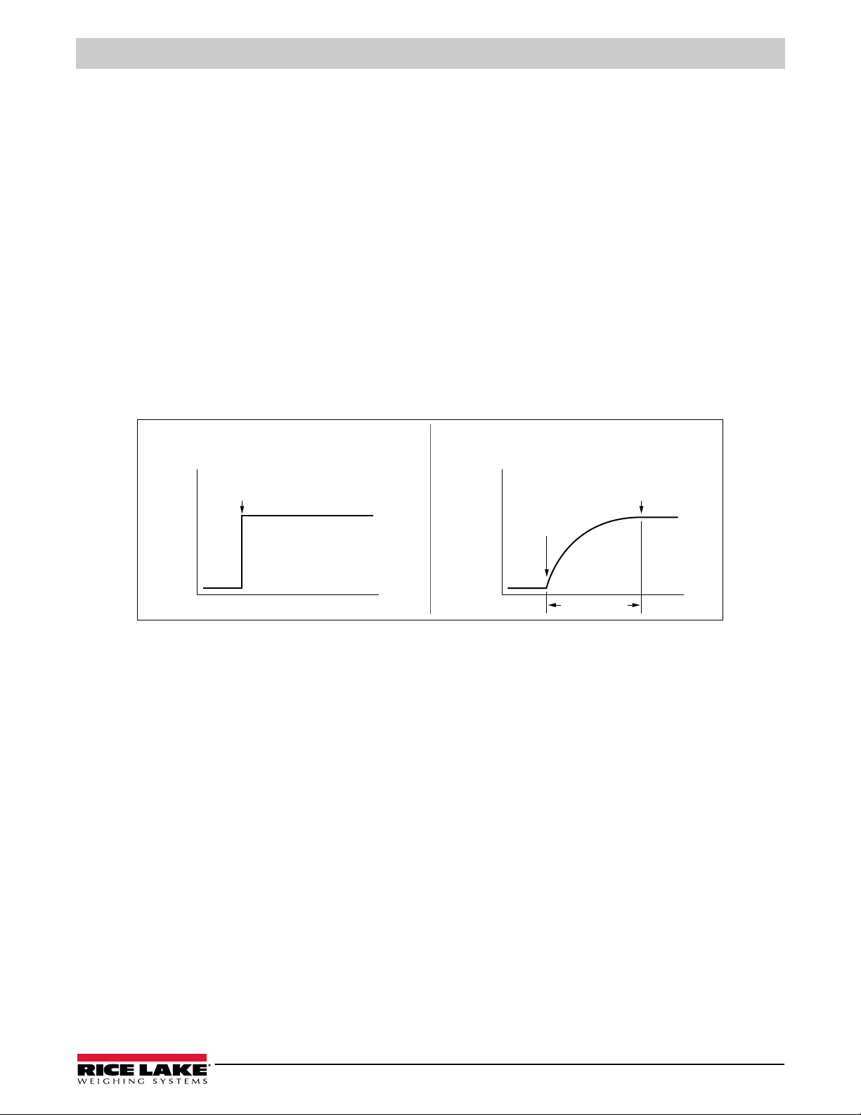
Appendix
0
500
0
500
DAMPVAL
When Full Weight
Value Displays
When Weight is Placed on Scale
and Full Weight Value Displays
When Weight
is Placed
on Scale
Adaptive Filter Threshold (ADTHRH)
Set the adaptive filtering threshold (ADTHRH) for the amount of observed instability in the system. This parameter can be set in
the range of 0–2000 and is entered as a weight value. When a new sampled weight value is acquired, the adaptive filter
compares the new value to the previous (filtered) output value.
If the difference between the new value and the previous output value is greater than the ADTHRH parameter the adaptive filter
is reset to the new weight value.
If the difference between the new value and the previous output value is less than the ADTHRH parameter, the two values are
averaged together using a weighted average. The weighted average is based on the amount of time the system has been
stable, and selected ADSENS sensitivity.
With the adaptive filter threshold set at zero, determine the amount of instability present. Enter this amount of weight instability
to set the threshold of the adaptive filter. The adaptive filter is set to OFF, the ADTHRH parameter is set to zero.
11.7.3 Damping Filter (DMPONLY)
The damping filter is a simple filter which adjusts the amount of time it takes for a change in weight to be processed through the
scale. The DAMPVAL parameter is a time interval specified in tenths of a second (10 = 1 second). This damping value is used
to determine the amount of time it takes for the scale to reach its final weight output. When DAMPVAL is set to ten, a transition
from 0 lb to 500 lb on the scale takes one second. The closer the weight gets to its final amount, the slower the weight changes
on the display.
With No Damping With Damping
Figure 11-5. 500 lb Displayed Weight Progression
© Rice Lake Weighing Systems ● All Rights Reserved 83
Page 84
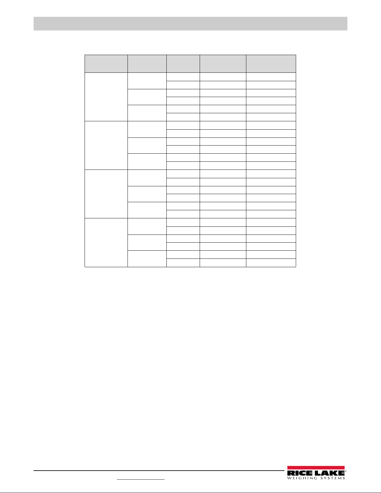
680 Synergy Plus
11.8 Regulatory Mode Functions
Regulatory
Parameter
NTEP Zero No “0000000” Zero
Canada Zero No “0000000” Zero
OIML Zero No “0000000” Zero
None Zero No “0000000” Zero
Weight On
Scale
Negative No No action Zero
Positive No Tare Zero
Negative No No action Zero
Positive No Tare Zero
Negative No No action Zero
Positive No “0000000” Zero
Negative No No action Zero
Positive No Tare Zero
Tare In
System
Yes Clear tare Zero
Yes Clear tare Zero
Yes Tare Zero
Yes Clear tare Clear tare
Yes Clear tare Clear tare
Yes No action Clear tare
Yes Clear tare Zero and Clear tare
Yes Clear tare Zero and Clear tare
Yes Tare Zero and Clear Tare
Yes Clear tare Clear tare
Yes Clear tare Clear tare
Yes Clear tare Clear tare
Front Panel
Key Tare
Table 11-5. Tare and Zero Key Functions for REGULA Parameter Settings
Front Panel
Key Zero
84 Visit our website www.RiceLake.com
Page 85
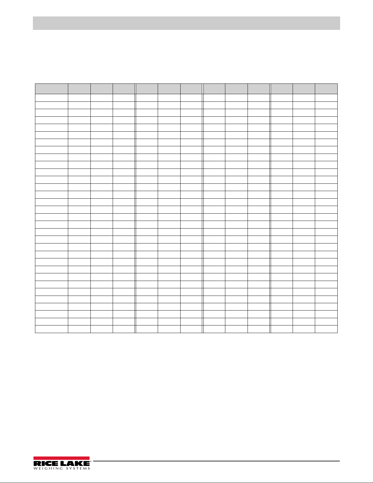
Appendix
11.9 ASCII Character Chart
Use the decimal values for ASCII characters listed in Table 11-6 when specifying print format strings on the 680 PFORMT menu
(Section 4.4.6 on page 44). The actual character printed depends on the character mapping used by the output device.
The 680 can send or receive ASCII character values (decimal 0–255), but the indicator display is limited to numbers, uppercase,
unaccented letters and a few special characters. See Section 11.10 on page 86 for information about the 680 LED display.
Control ASCII Dec Hex ASCII Dec Hex ASCII Dec Hex ASCII Dec Hex
Ctrl-@ NUL 00 00 space 32 20 @ 64 40 ` 96 60
Ctrl-A SOH 01 01 ! 33 21 A 65 41 a 97 61
Ctrl-B STX 02 02 “ 34 22 B 66 42 b 98 62
Ctrl-C ETX 03 03 # 35 23 C 67 43 c 99 63
Ctrl-D EOT 04 04 $ 36 24 D 68 44 d 100 64
Ctrl-E ENQ 05 05 % 37 25 E 69 45 e 101 65
Ctrl-F ACK 06 06 & 38 26 F 70 46 f 102 66
Ctrl-G BEL 07 07 ’ 39 27 G 71 47 g 103 67
Ctrl-H BS 08 08 ( 40 28 H 72 48 h 104 68
Ctrl-I HT 09 09 ) 41 29 I 73 49 i 105 69
Ctrl-J LF 10 0A * 42 2A J 74 4A j 106 6A
Ctrl-K VT 11 0B + 43 2B K 75 4B k 107 6B
Ctrl-L FF 12 0C , 44 2C L 76 4C l 108 6C
Ctrl-M CR 13 0D - 45 2D M 77 4D m 109 6D
Ctrl-N SO 14 0E . 46 2E N 78 4E n 110 6E
Ctrl-O SI 15 0F / 47 2F O 79 4F o 111 6F
Ctrl-P DLE 16 10 0 48 30 P 80 50 p 112 70
Ctrl-Q DC1 17 11 1 49 31 Q 81 51 q 113 71
Ctrl-R DC2 18 12 2 50 32 R 82 52 r 114 72
Ctrl-S DC3 19 13 3 51 33 S 83 53 s 115 73
Ctrl-T DC4 20 14 4 52 34 T 84 54 t 116 74
Ctrl-U NAK 21 15 5 53 35 U 85 55 u 117 75
Ctrl-V SYN 22 16 6 54 36 V 86 56 v 118 76
Ctrl-W ETB 23 17 7 55 37 W 87 57 w 119 77
Ctrl-X CAN 24 18 8 56 38 X 88 58 x 120 78
Ctrl-Y EM 25 19 9 57 39 Y 89 59 y 121 79
Ctrl-Z SUB 26 1A : 58 3A Z 90 5A z 122 7A
Ctrl-[ ESC 27 1B ; 59 3B [ 91 5B { 123 7B
Ctrl-\ FS 28 1C < 60 3C \ 92 5C | 124 7C
Ctrl-] GS 29 1D = 61 3D ] 93 5D } 125 7D
Ctrl-^ RS 30 1E > 62 3E ^ 94
Ctrl-_ US 31 1F ? 63 3F _ 95 5F DEL 127 7F
Table 11-6. ASCII Character Chart
5E ~ 126 7
E
© Rice Lake Weighing Systems ● All Rights Reserved 85
Page 86
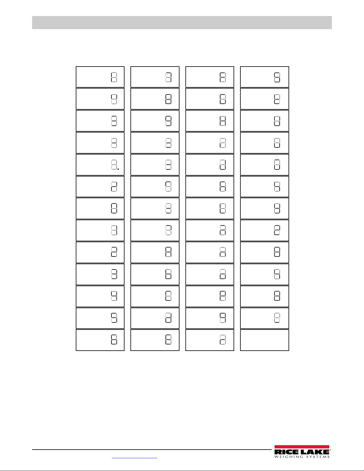
680 Synergy Plus
! 7 Ff Ss
" 8 Gg Tt
+ 9 Hh Uu
- : Ii Vv
. ; Jj Ww
/ < Kk Xx
0 = Ll Yy
1 > Mm Zz
2 Aa Nn [
3 Bb Oo \
4 Cc Pp ]
5 Dd Qq _
6 Ee Rr
11.10 Front Panel Display Characters
Refer to Figure 11-6 for the seven-segment LED character set used on the 680 front panel display for alphanumeric characters.
Figure 11-6. 680 Display Characters
86 Visit our website www.RiceLake.com
Page 87
12.0 Compliance
5LFH/DNH:HLJKLQJ6\VWHPV
:HVW &ROHPDQ 6WUHHW
5LFH /DNH :LVFRQVLQ
8QLWHG 6WDWHV RI $PHULFD
6LJQDWXUH
3ODFH
1DPH 'DWH
7LWOH
(8DECLARATIONOF
CONFORMITY
("#+,.$-#0#(1
#/ ( #&1
(88'LUHFWLYH &HUWLILFDWHV
6WDQGDUGVV8VHGG1RWLILHGG%RG\\,QYROYHPHQWW
7\SH7\S7\SH
(QJOLVK :H GHFODUHXQGHU RXU VROHUHVSRQVLELOLW\ WKDW WKH SURGXFWVWRZKLFK WKLV GHFODUDWLRQUHIHUV WR LV LQFRQIRUPLW\ ZLWK WKHIROORZLQJ
VWDQGDUGV RURWKHUUHJXODWLRQV GRFXPHQWV
'HXWVFK :LUHUNOlUHQXQWHU XQVHUHUDOOHLQLJHQ 9HUDQWZRUWXQJ GDVV GLH 3URGXNWH DXIGLHVLFK GLHVH (UNOlUXQJEH]LHKW GHQIROJHQGHQ 1RUPHQ
XQG 5HJXOLHUXQJVEHVWLPPXQJHQ HQWVSUHFKHQ
)UDQFDLV 1RXVGpFODURQVVRXVQRWUHUHVSRQVDELOLWpTXHOHVSURGXLWVDX[TXHOVVHUDSSRUWHODSUpVHQWHGpFODUWLRQVRQWFRQIRUPHVjODDX[QRUPHV
VXLYDQWHRXDXDX[GRFXPHQWVQRUPDWLIVVXLYDQWV
BBBBBBBBBBBBBBBBBBBBBBBBBBBBBBBBBBBBB
BBBBBBBBBBBBBBBBBBBBBBBBBBBBBBBBBBBBB
BBBBBBBBBBBBBBBBBBBBBBBBBBBBBBBBBBBBB
BBBBBBBBBBBBBBBBBBBBBBBBBBBBBBBBBBBBB
BBBBBBBBBBBBBBBBBBBBBBBBBBBBBBBBBBBBB
BBBBBBBBBBBBBBBBBBBBBBBBBBBBBBBBBBBBBBBBBBBBBBBBBBBBBBBBBBBBBBBBBBBBBBBBBB
BBBBBBBBBBBBBBBBBBBBBBBBBBBBBBBBBBBBB
BB
B
BB
B
BBBBBBBBBBBBBBBBBB
B
BBBBBBBBBBBBBBBBBB
B
Compliance
680, 680HE and 682 indicator series
22014/35/EU LVD
2014/30/EU EMC
2014/53/EU RED
2011/65/EU RoHS
-
-
-
-
680: IEC 61010-1:2010+A1:2016
682, 680HE: EN 62368-1:2014 + A11:2017
EN 61326-1:2013, EN 61000-3-3:2013, EN 61000-6-2, EN 61000-6-4,
EN55011:2009/A1:2010
EN 301 489-17 V3.2.4, EN 300 328 V2.2.2, EN 301 893 V2.1.1
EN 50581:2012
Brandi Harder
Quality Manager
Rice Lake, WI USA
March 30, 2022
© Rice Lake Weighing Systems ● All Rights Reserved 87
Page 88

680 Synergy Plus
5LFH/DNH:HLJKLQJ6\VWHPV
:HVW &ROHPDQ 6WUHHW
5LFH /DNH :LVFRQVLQ
8QLWHG 6WDWHV RI $PHULFD
6LJQDWXUH
3ODFH
1DPH 'DWH
7LWOH
8. DECLARATION
OFCONFORMITY
8..5HJXODWLRQV &HUWLILFDWHV
6WDQGDUGVV8VHGG$SSURYHGG%RG\\,QYROYHPHQWW
7\SH
(QJOLVK :H GHFODUHXQGHU RXU VROHUHVSRQVLELOLW\ WKDW WKH SURGXFWV WRZKLFKWKLV GHFODUDWLRQUHIHUVWR LV LQFRQIRUPLW\ ZLWKWKHIROORZLQJ
VWDQGDUGV RURWKHUUHJXODWLRQV GRFXPHQWV
BBBBBBBBBBBBBBBBBBBBBBBBBBBBBBBBBBBBB
BBBBBBBBBBBBBBBBBBBBBBBBBBBBBBBBBBBBB
BBBBBBBBBBBBBBBBBBBBBBBBBBBBBBBBBBBBB
BBBBBBBBBBBBBBBBBBBBBBBBBBBBBBBBBBBBB
BBBBBBBBBBBBBBBBBBBBBBBBBBBBBBBBBBBBB
BBBBBBBBBBBBBBBBBB
BBBB
B
BB
BBBBB
BBB
680, 680HE and 682 indicator series
2016/1101 Low Voltage
2016/1091 EMC
2017/1206 Radio
2012/3032 RoHS
-
-
-
-
680: IEC 61010-1:2010+A1:2016
682, 680HE: EN 62368-1:2014 + A11:2017
EN 61326-1:2013, EN 61000-3-3:2013, EN 61000-6-2, EN 61000-6-4,
EN55011:2009/A1:2010
EN 301 489-17 V3.2.4, EN 300 328 V2.2.2, EN 301 893 V2.1.1
EN 50581:2012
Brandi Harder
Quality manager
88 Visit our website www.RiceLake.com
Rice Lake, WI USA
March 30, 2022
Page 89

13.0 Specifications
Measurement
Canada
Approved
Power
AC line voltage: 120–240 VAC, 50–60 Hz
DC line voltage: 9–36 VDC, LPS (Class 2) / PS2 powered
Power Consumption
~2 W (AC) with one 350 Ω load cell, 15 W max
Excitation Voltage
10 VDC bi-polar (± 5 VDC), 8 x 350 Ω or 16 x 700 Ωload cells
Analog Output (Optional)
Resolution: 16-bit, monotonicity over temperature
Linearity: ±0.03% of full scale input
Voltage output: 0–10 VDC
Voltage load resistance: 1 KΩ minimum
Current output: 0–20 mA or 4–20 mA (20% offset)
Current loop resistance: 1 KΩ maximum
Analog Signal Input Range
-5 mV to +70 mV
Specifications
Rating / Material
Rating: IP69K
IP66 (with RJ45 option)
Material: AISI 304 Stainless Steel
Dimensions (W x H x D)
Indicator and Stand 11.58 x 8.57 x 4.05 in
(29.41 x 21.77 x 10.29 cm)
Indicator and Stand 11.58 x 8.57 x 4.74 in
with RJ45 Option (29.41 x 21.77 x 12.04 cm)
Weight
6.25 lb (2.84 kg)
Warranty
Two-year limited warranty
EMC Immunity
10 V/m
Analog Signal Sensitivity
Recommended: 1 µV/graduation
A/D Sample Rate
6.25–120 Hz, software selectable
Resolution
Internal: 8,000,000 counts
Display: 1,000,000
System Linearity / PI Rating
Within 0.01% full scale
Digital I/O
Four configurable I/O (5 V logic)
Communication Ports
Two RS-232 (three-wire)
RS-485/422 (two-wire or four-wire)
Micro USB (device)
Ethernet (10/100)
Status Annunciators
Eight LED annunciators
Display
Seven 0.8'' (20 mm) tall, seven-segment digits
Certifications and Approvals
NTEP
CoC Number: 19-021
Accuracy Class: III / IIIL; n
Measurement Canada
Approval No. AM-6121C
Accuracy Class: III / IIIHD; n
UL
File Number: E505539
OIML
File Number: R76/2006-A-NL1-19.56
Accuracy Class: III / IIII; n
max
max
: 10000
: 10000
max
: 10000
Keys / Buttons
Flat membrane panel, tactile feel (18 buttons plus power)
Temperature Range
Legal: 14–104°F (-10–40°C)
Industrial: 14–122°F (-10–50°C)
Environmental
Intended environment: Pollution Degree 3
Wet location: Rated for washdown environments
Recommended use: Indoor
© Rice Lake Weighing Systems ● All Rights Reserved 89
Page 90

680 Synergy Plus
90 Visit our website www.RiceLake.com
Page 91

Page 92

© Rice Lake Weighing Systems Content subject to change without notice.
230 W. Coleman St. ▪ Rice Lake, WI 54868 ▪ USA USA: 800-472-6703 ▪ International +1-715-234-9171
www.ricelake.com
November 7, 2023 PN 192627 Rev N
 Loading...