

Page 1

Presented By
Dallas HoustonAustinFt Worth
NicolScales.com
800.225.8181
Contact Us
Nicol Scales & Measurement is an ISO Accredited Calibration
Company that has provided calibration, repair and sales of all types
of weighing and measurement products since 1931.
Page 2
480 Legend Series
Disponible
en Español
Visite ricelake.com/spanish
para ver todos los materiales
RLWS disponibles en Español
Digital Weight Indicator
Version 1.05
Technical Manual
PN 119201 Rev K
Page 3

Page 4

Contents
Technical training seminars are available through Rice Lake Weighing Systems.
Course descriptions and dates can be viewed at www.ricelake.com/training
or obtained by calling 715-234-9171 and asking for the training department.
1.0 Introduction..................................................................................................................................... 1
1.1 Safety . . . . . . . . . . . . . . . . . . . . . . . . . . . . . . . . . . . . . . . . . . . . . . . . . . . . . . . . . . . . . . . . . . . . . . . . . . 1
1.2 Overview . . . . . . . . . . . . . . . . . . . . . . . . . . . . . . . . . . . . . . . . . . . . . . . . . . . . . . . . . . . . . . . . . . . . . . . . 2
1.3 Operating Modes. . . . . . . . . . . . . . . . . . . . . . . . . . . . . . . . . . . . . . . . . . . . . . . . . . . . . . . . . . . . . . . . . . 2
1.4 Front Panel Keypad . . . . . . . . . . . . . . . . . . . . . . . . . . . . . . . . . . . . . . . . . . . . . . . . . . . . . . . . . . . . . . . . 3
1.5 Keypad Functions . . . . . . . . . . . . . . . . . . . . . . . . . . . . . . . . . . . . . . . . . . . . . . . . . . . . . . . . . . . . . . . . . 3
1.6 LED Annunciators . . . . . . . . . . . . . . . . . . . . . . . . . . . . . . . . . . . . . . . . . . . . . . . . . . . . . . . . . . . . . . . . . 4
1.7 Front Panel Navigation. . . . . . . . . . . . . . . . . . . . . . . . . . . . . . . . . . . . . . . . . . . . . . . . . . . . . . . . . . . . . . 4
1.7.1 Numeric Keypad - Editing Procedure for Numeric Values (480 Plus Only) . . . . . . . . . . . . . . . . . . . . . . . . . 5
1.8 Indicator Operations . . . . . . . . . . . . . . . . . . . . . . . . . . . . . . . . . . . . . . . . . . . . . . . . . . . . . . . . . . . . . . . 6
1.8.1 Menu . . . . . . . . . . . . . . . . . . . . . . . . . . . . . . . . . . . . . . . . . . . . . . . . . . . . . . . . . . . . . . . . . . . . . . . . . . . . 6
1.8.2 Status Lights While in Various Menus . . . . . . . . . . . . . . . . . . . . . . . . . . . . . . . . . . . . . . . . . . . . . . . . . . . . 6
1.8.3 Zero Scale . . . . . . . . . . . . . . . . . . . . . . . . . . . . . . . . . . . . . . . . . . . . . . . . . . . . . . . . . . . . . . . . . . . . . . . . 6
1.8.4 Toggle Units . . . . . . . . . . . . . . . . . . . . . . . . . . . . . . . . . . . . . . . . . . . . . . . . . . . . . . . . . . . . . . . . . . . . . . . 6
1.8.5 Acquire Tare . . . . . . . . . . . . . . . . . . . . . . . . . . . . . . . . . . . . . . . . . . . . . . . . . . . . . . . . . . . . . . . . . . . . . . . 6
1.8.6 Preset Tare (Keyed Tare). . . . . . . . . . . . . . . . . . . . . . . . . . . . . . . . . . . . . . . . . . . . . . . . . . . . . . . . . . . . . . 7
1.8.7 Display Tare . . . . . . . . . . . . . . . . . . . . . . . . . . . . . . . . . . . . . . . . . . . . . . . . . . . . . . . . . . . . . . . . . . . . . . . 7
1.8.8 Print Ticket . . . . . . . . . . . . . . . . . . . . . . . . . . . . . . . . . . . . . . . . . . . . . . . . . . . . . . . . . . . . . . . . . . . . . . . . 7
1.8.9 Toggle Gross/Net Mode . . . . . . . . . . . . . . . . . . . . . . . . . . . . . . . . . . . . . . . . . . . . . . . . . . . . . . . . . . . . . . 7
1.8.10 View Audit Trail . . . . . . . . . . . . . . . . . . . . . . . . . . . . . . . . . . . . . . . . . . . . . . . . . . . . . . . . . . . . . . . . . . . . . 7
1.8.11 Enter New Unit ID . . . . . . . . . . . . . . . . . . . . . . . . . . . . . . . . . . . . . . . . . . . . . . . . . . . . . . . . . . . . . . . . . . . 8
1.8.12 Display Accumulator . . . . . . . . . . . . . . . . . . . . . . . . . . . . . . . . . . . . . . . . . . . . . . . . . . . . . . . . . . . . . . . . . 8
1.8.13 Display or Change Time and Date. . . . . . . . . . . . . . . . . . . . . . . . . . . . . . . . . . . . . . . . . . . . . . . . . . . . . . . 8
1.8.14 Display, Edit and Set Setpoint Value . . . . . . . . . . . . . . . . . . . . . . . . . . . . . . . . . . . . . . . . . . . . . . . . . . . . . 9
1.8.15 View Firmware Version . . . . . . . . . . . . . . . . . . . . . . . . . . . . . . . . . . . . . . . . . . . . . . . . . . . . . . . . . . . . . . . 9
1.8.16 Enter User Password . . . . . . . . . . . . . . . . . . . . . . . . . . . . . . . . . . . . . . . . . . . . . . . . . . . . . . . . . . . . . . . . 9
2.0 Installation .................................................................................................................................... 10
2.1 Unpacking . . . . . . . . . . . . . . . . . . . . . . . . . . . . . . . . . . . . . . . . . . . . . . . . . . . . . . . . . . . . . . . . . . . . . . 10
2.2 Enclosure Disassembly . . . . . . . . . . . . . . . . . . . . . . . . . . . . . . . . . . . . . . . . . . . . . . . . . . . . . . . . . . . . 10
2.3 Cable Connections . . . . . . . . . . . . . . . . . . . . . . . . . . . . . . . . . . . . . . . . . . . . . . . . . . . . . . . . . . . . . . . 10
2.3.1 Cable Grounding. . . . . . . . . . . . . . . . . . . . . . . . . . . . . . . . . . . . . . . . . . . . . . . . . . . . . . . . . . . . . . . . . . . 11
2.3.2 Wiring . . . . . . . . . . . . . . . . . . . . . . . . . . . . . . . . . . . . . . . . . . . . . . . . . . . . . . . . . . . . . . . . . . . . . . . . . . . 12
2.4 Battery Operation . . . . . . . . . . . . . . . . . . . . . . . . . . . . . . . . . . . . . . . . . . . . . . . . . . . . . . . . . . . . . . . . 14
2.5 Option Card Installation . . . . . . . . . . . . . . . . . . . . . . . . . . . . . . . . . . . . . . . . . . . . . . . . . . . . . . . . . . . . 15
2.6 Board Removal . . . . . . . . . . . . . . . . . . . . . . . . . . . . . . . . . . . . . . . . . . . . . . . . . . . . . . . . . . . . . . . . . . 15
2.7 Enclosure Reassembly. . . . . . . . . . . . . . . . . . . . . . . . . . . . . . . . . . . . . . . . . . . . . . . . . . . . . . . . . . . . . 16
2.7.1 Seal the Indicator (Optional) . . . . . . . . . . . . . . . . . . . . . . . . . . . . . . . . . . . . . . . . . . . . . . . . . . . . . . . . . . 17
2.8 Replacement Parts . . . . . . . . . . . . . . . . . . . . . . . . . . . . . . . . . . . . . . . . . . . . . . . . . . . . . . . . . . . . . . . 18
3.0 Configuration ................................................................................................................................ 20
3.1 User Menu Setup. . . . . . . . . . . . . . . . . . . . . . . . . . . . . . . . . . . . . . . . . . . . . . . . . . . . . . . . . . . . . . . . . 22
3.1.1 Setpoint Menu . . . . . . . . . . . . . . . . . . . . . . . . . . . . . . . . . . . . . . . . . . . . . . . . . . . . . . . . . . . . . . . . . . . . 23
3.1.2 Serial Menu. . . . . . . . . . . . . . . . . . . . . . . . . . . . . . . . . . . . . . . . . . . . . . . . . . . . . . . . . . . . . . . . . . . . . . . 25
3.1.3 Ethernet Menu . . . . . . . . . . . . . . . . . . . . . . . . . . . . . . . . . . . . . . . . . . . . . . . . . . . . . . . . . . . . . . . . . . . . 28
3.1.4 USB Menu . . . . . . . . . . . . . . . . . . . . . . . . . . . . . . . . . . . . . . . . . . . . . . . . . . . . . . . . . . . . . . . . . . . . . . . 29
3.1.5 Print Format Menu . . . . . . . . . . . . . . . . . . . . . . . . . . . . . . . . . . . . . . . . . . . . . . . . . . . . . . . . . . . . . . . . . 30
3.1.6 Version Menu . . . . . . . . . . . . . . . . . . . . . . . . . . . . . . . . . . . . . . . . . . . . . . . . . . . . . . . . . . . . . . . . . . . . . 30
3.1.7 MISC Menu. . . . . . . . . . . . . . . . . . . . . . . . . . . . . . . . . . . . . . . . . . . . . . . . . . . . . . . . . . . . . . . . . . . . . . . 31
© Rice Lake Weighing Systems. All rights reserved.
Specifications subject to change without notice.
Rice Lake Weighing Systems is an ISO 9001 registered company.
Version 1.05, January 14, 2016
Contents i
Page 5

3.2 Configuration Using the Front Panel (Legal for Trade). . . . . . . . . . . . . . . . . . . . . . . . . . . . . . . . . . . . . . 32
Rice Lake continually offers web-based video training on a growing selection
of product-related topics at no cost. Visit www.ricelake.com/webinars
3.2.1 Configuration Menu Structures and Parameter Descriptions . . . . . . . . . . . . . . . . . . . . . . . . . . . . . . . . . . 33
3.2.2 Adaptive Filter and Rolling Filter Sub-menu Parameters . . . . . . . . . . . . . . . . . . . . . . . . . . . . . . . . . . . . . 34
3.2.3 Format Menu . . . . . . . . . . . . . . . . . . . . . . . . . . . . . . . . . . . . . . . . . . . . . . . . . . . . . . . . . . . . . . . . . . . . . 36
3.2.4 Calibration Menu. . . . . . . . . . . . . . . . . . . . . . . . . . . . . . . . . . . . . . . . . . . . . . . . . . . . . . . . . . . . . . . . . . . 37
3.2.5 Program Menu . . . . . . . . . . . . . . . . . . . . . . . . . . . . . . . . . . . . . . . . . . . . . . . . . . . . . . . . . . . . . . . . . . . . 38
3.2.6 Digital Input Menu . . . . . . . . . . . . . . . . . . . . . . . . . . . . . . . . . . . . . . . . . . . . . . . . . . . . . . . . . . . . . . . . . 41
3.2.7 Analog Output Menu. . . . . . . . . . . . . . . . . . . . . . . . . . . . . . . . . . . . . . . . . . . . . . . . . . . . . . . . . . . . . . . . 42
3.2.8 Password Menu . . . . . . . . . . . . . . . . . . . . . . . . . . . . . . . . . . . . . . . . . . . . . . . . . . . . . . . . . . . . . . . . . . . 43
3.2.9 USBMEM Menu . . . . . . . . . . . . . . . . . . . . . . . . . . . . . . . . . . . . . . . . . . . . . . . . . . . . . . . . . . . . . . . . . . . 43
3.2.10 Test Menu . . . . . . . . . . . . . . . . . . . . . . . . . . . . . . . . . . . . . . . . . . . . . . . . . . . . . . . . . . . . . . . . . . . . . . . 44
3.2.11 User Menu Setup . . . . . . . . . . . . . . . . . . . . . . . . . . . . . . . . . . . . . . . . . . . . . . . . . . . . . . . . . . . . . . . . . . 44
3.3 Revolution® Configuration . . . . . . . . . . . . . . . . . . . . . . . . . . . . . . . . . . . . . . . . . . . . . . . . . . . . . . . . . . 45
4.0 Calibration .................................................................................................................................... 46
4.1 Front Panel Calibration. . . . . . . . . . . . . . . . . . . . . . . . . . . . . . . . . . . . . . . . . . . . . . . . . . . . . . . . . . . . . 46
4.2 EDP Command Calibration . . . . . . . . . . . . . . . . . . . . . . . . . . . . . . . . . . . . . . . . . . . . . . . . . . . . . . . . . 47
4.3 Revolution Calibration . . . . . . . . . . . . . . . . . . . . . . . . . . . . . . . . . . . . . . . . . . . . . . . . . . . . . . . . . . . . . 47
4.4 More About Calibration . . . . . . . . . . . . . . . . . . . . . . . . . . . . . . . . . . . . . . . . . . . . . . . . . . . . . . . . . . . . 48
4.4.1 Adjusting Final Calibration. . . . . . . . . . . . . . . . . . . . . . . . . . . . . . . . . . . . . . . . . . . . . . . . . . . . . . . . . . . . 48
5.0 Revolution ..................................................................................................................................... 49
5.1 Connecting to the Indicator . . . . . . . . . . . . . . . . . . . . . . . . . . . . . . . . . . . . . . . . . . . . . . . . . . . . . . . . . 49
5.2 Saving and Transferring Data. . . . . . . . . . . . . . . . . . . . . . . . . . . . . . . . . . . . . . . . . . . . . . . . . . . . . . . . 49
5.2.1 Saving Indicator Data to a Personal Computer . . . . . . . . . . . . . . . . . . . . . . . . . . . . . . . . . . . . . . . . . . . . 49
5.2.2 Downloading Configuration Data from PC to Indicator . . . . . . . . . . . . . . . . . . . . . . . . . . . . . . . . . . . . . . 49
5.3 Reflash Indicator . . . . . . . . . . . . . . . . . . . . . . . . . . . . . . . . . . . . . . . . . . . . . . . . . . . . . . . . . . . . . . . . . 50
5.3.1 480/482 Legend Series Flash Loader . . . . . . . . . . . . . . . . . . . . . . . . . . . . . . . . . . . . . . . . . . . . . . . . . . . 50
5.3.2 480/482 Legend Series Firmware Update. . . . . . . . . . . . . . . . . . . . . . . . . . . . . . . . . . . . . . . . . . . . . . . . 50
6.0 EDP Commands............................................................................................................................. 51
6.1 The EDP Command Set . . . . . . . . . . . . . . . . . . . . . . . . . . . . . . . . . . . . . . . . . . . . . . . . . . . . . . . . . . . 51
6.1.1 Key Press Commands . . . . . . . . . . . . . . . . . . . . . . . . . . . . . . . . . . . . . . . . . . . . . . . . . . . . . . . . . . . . . . 51
6.1.2 Reporting Commands. . . . . . . . . . . . . . . . . . . . . . . . . . . . . . . . . . . . . . . . . . . . . . . . . . . . . . . . . . . . . . . 52
6.1.3 The RESETCONFIGURATION Command . . . . . . . . . . . . . . . . . . . . . . . . . . . . . . . . . . . . . . . . . . . . . . . . 52
6.1.4 Parameter Setting Commands . . . . . . . . . . . . . . . . . . . . . . . . . . . . . . . . . . . . . . . . . . . . . . . . . . . . . . . . 52
6.1.5 Soft Reset. . . . . . . . . . . . . . . . . . . . . . . . . . . . . . . . . . . . . . . . . . . . . . . . . . . . . . . . . . . . . . . . . . . . . . . . 52
6.1.6 Normal Mode Commands. . . . . . . . . . . . . . . . . . . . . . . . . . . . . . . . . . . . . . . . . . . . . . . . . . . . . . . . . . . . 56
7.0 Print Formatting ............................................................................................................................ 57
7.1 Print Formatting Tokens. . . . . . . . . . . . . . . . . . . . . . . . . . . . . . . . . . . . . . . . . . . . . . . . . . . . . . . . . . . . 57
7.2 Customizing Print Formats. . . . . . . . . . . . . . . . . . . . . . . . . . . . . . . . . . . . . . . . . . . . . . . . . . . . . . . . . . 58
7.2.1 Using the Front Panel . . . . . . . . . . . . . . . . . . . . . . . . . . . . . . . . . . . . . . . . . . . . . . . . . . . . . . . . . . . . . . . 58
8.0 Setpoints ....................................................................................................................................... 59
8.1 Batch and Continuous Setpoints . . . . . . . . . . . . . . . . . . . . . . . . . . . . . . . . . . . . . . . . . . . . . . . . . . . . . 59
9.0 Appendix ....................................................................................................................................... 60
9.1 Error Messages . . . . . . . . . . . . . . . . . . . . . . . . . . . . . . . . . . . . . . . . . . . . . . . . . . . . . . . . . . . . . . . . . . 60
9.1.1 Displayed Error Messages . . . . . . . . . . . . . . . . . . . . . . . . . . . . . . . . . . . . . . . . . . . . . . . . . . . . . . . . . . . 60
9.1.2 Using the XE EDP Command . . . . . . . . . . . . . . . . . . . . . . . . . . . . . . . . . . . . . . . . . . . . . . . . . . . . . . . . . 61
9.2 Status Messages . . . . . . . . . . . . . . . . . . . . . . . . . . . . . . . . . . . . . . . . . . . . . . . . . . . . . . . . . . . . . . . . . 61
9.2.1 P EDP Command . . . . . . . . . . . . . . . . . . . . . . . . . . . . . . . . . . . . . . . . . . . . . . . . . . . . . . . . . . . . . . . . . . 61
9.2.2 ZZ EDP Command . . . . . . . . . . . . . . . . . . . . . . . . . . . . . . . . . . . . . . . . . . . . . . . . . . . . . . . . . . . . . . . . . 61
9.3 Continuous Data (Stream) Output Formats . . . . . . . . . . . . . . . . . . . . . . . . . . . . . . . . . . . . . . . . . . . . . 62
9.4 Local/Remote Operation . . . . . . . . . . . . . . . . . . . . . . . . . . . . . . . . . . . . . . . . . . . . . . . . . . . . . . . . . . . 65
9.5 Audit Trail Support. . . . . . . . . . . . . . . . . . . . . . . . . . . . . . . . . . . . . . . . . . . . . . . . . . . . . . . . . . . . . . . . 65
9.6 Sleep Mode . . . . . . . . . . . . . . . . . . . . . . . . . . . . . . . . . . . . . . . . . . . . . . . . . . . . . . . . . . . . . . . . . . . . . 65
9.7 Internal Battery Option. . . . . . . . . . . . . . . . . . . . . . . . . . . . . . . . . . . . . . . . . . . . . . . . . . . . . . . . . . . . . 66
ii 480 Legend Series
Page 6

9.8 USB Option . . . . . . . . . . . . . . . . . . . . . . . . . . . . . . . . . . . . . . . . . . . . . . . . . . . . . . . . . . . . . . . . . . . . . 66
9.8.1 HOST . . . . . . . . . . . . . . . . . . . . . . . . . . . . . . . . . . . . . . . . . . . . . . . . . . . . . . . . . . . . . . . . . . . . . . . . . . . 66
9.8.2 Flash Drive . . . . . . . . . . . . . . . . . . . . . . . . . . . . . . . . . . . . . . . . . . . . . . . . . . . . . . . . . . . . . . . . . . . . . . . 66
9.8.3 USB Printing. . . . . . . . . . . . . . . . . . . . . . . . . . . . . . . . . . . . . . . . . . . . . . . . . . . . . . . . . . . . . . . . . . . . . . 67
9.9 Ethernet Option . . . . . . . . . . . . . . . . . . . . . . . . . . . . . . . . . . . . . . . . . . . . . . . . . . . . . . . . . . . . . . . . . . 67
9.10 Conversion Factors for Secondary Units . . . . . . . . . . . . . . . . . . . . . . . . . . . . . . . . . . . . . . . . . . . . . . 68
9.11 Digital Filtering (DIGFIL) . . . . . . . . . . . . . . . . . . . . . . . . . . . . . . . . . . . . . . . . . . . . . . . . . . . . . . . . . . . 68
9.11.1 Sample Rate (SMPRAT) . . . . . . . . . . . . . . . . . . . . . . . . . . . . . . . . . . . . . . . . . . . . . . . . . . . . . . . . . . . . . 68
9.11.2 Adaptive Filter. . . . . . . . . . . . . . . . . . . . . . . . . . . . . . . . . . . . . . . . . . . . . . . . . . . . . . . . . . . . . . . . . . . . . 68
9.11.3 Rolling Averaging Filter . . . . . . . . . . . . . . . . . . . . . . . . . . . . . . . . . . . . . . . . . . . . . . . . . . . . . . . . . . . . . . 69
9.12 Analog Output Calibration . . . . . . . . . . . . . . . . . . . . . . . . . . . . . . . . . . . . . . . . . . . . . . . . . . . . . . . . . 70
9.13 Test Mode . . . . . . . . . . . . . . . . . . . . . . . . . . . . . . . . . . . . . . . . . . . . . . . . . . . . . . . . . . . . . . . . . . . . . 70
9.14 Regulatory Mode Functions . . . . . . . . . . . . . . . . . . . . . . . . . . . . . . . . . . . . . . . . . . . . . . . . . . . . . . . . 71
9.15 ASCII Character Chart . . . . . . . . . . . . . . . . . . . . . . . . . . . . . . . . . . . . . . . . . . . . . . . . . . . . . . . . . . . . 72
9.16 Front Panel Display Characters . . . . . . . . . . . . . . . . . . . . . . . . . . . . . . . . . . . . . . . . . . . . . . . . . . . . . 74
9.17 Specifications. . . . . . . . . . . . . . . . . . . . . . . . . . . . . . . . . . . . . . . . . . . . . . . . . . . . . . . . . . . . . . . . . . . 75
Contents iii
Page 7

iv 480 Legend Series
Page 8
1.0 Introduction
WARNING
Important
WARNING
This manual is intended for use by service technicians responsible for installing and servicing 480 digital weight
indicators. This manual applies to indicators using Version 1.05 of the 480 software.
Configuration and calibration of the indicator can be accomplished using the Revolution
the indicator front panel keys. See Section 3.2 on page 32 for information about configuration methods.
Manuals can be viewed or downloaded from the Rice Lake Weighing Systems website at
www.ricelake.com.
An Operation Manual is available on the website, that provides basic operating instructions for users.
Warranty information can be found on the website at
www.ricelake.com/warranties
1. 1 S af e ty
Safety Symbol Definitions
Indicates a potentially hazardous situation that, if not avoided, could result in serious injury or death, and
includes hazards that are exposed when guards are removed.
Indicates information about procedures that, if not observed, could result in damage to equipment or
corruption to and loss of data.
Safety Precautions
Do not operate or work on this equipment unless you have read and understand the instructions and
warnings in this manual. Failure to follow the instructions or heed the warnings could result in injury or
death. Contact any Rice Lake Weighing Systems dealer for replacement manuals. Proper care is your
responsibility.
®
configuration utility or
General Safety
Failure to heed may result in serious injury or death.
Some procedures described in this manual require work inside the indicator enclosure. These procedures are to be
performed by qualified service personnel only.
Do not allow minors (children) or inexperienced persons to operate this unit.
Do not operate without the enclosure completely assembled.
Do not use for purposes other than weight taking.
Do not place fingers into slots or possible pinch points.
Do not use this product if any of the components are cracked.
Do not exceed the rated specification of the unit. See Section 9.17 on page 75.
Do not make alterations or modifications to the unit.
Do not remove or obscure warning labels.
Do not submerge.
Before opening the unit, ensure the power cord is disconnected from the outlet.
Introduction 1
Page 9

1. 2 O ve r vi e w
The 480 is a single-channel digital weight indicator housed in a NEMA Type 4X/IP66-rated stainless steel
enclosure. The indicator front panel consists of a large (.8 in/20 mm), six-digit, seven-segment LED display , with a
seven-button keypad (480) or an 18-button full numeric keypad (480 Plus).
Features
• Auto switching AC power supply 115 VAC to 230 VAC (50-60 Hz)
• Drives up to ten 350 ohmor twenty 700 ohm load cells
• Supports four and six wire load cell connections
• Two communications ports with demand or continuous (COM 2 only) outputs
• Unit ID, operator can enter up to six numeric digits
• Accumulator with report and clear
• Time and date
• Audit trail tracking
• Optional Ethernet/USB connects to PC or printer in operation mode, or flash drive to save/load
configuration
• Optional analog output module provides 0–10/2-10 VDC or 0–20/4–20 mA tracking of gross/net weight
• Optional digital I/O card, four outputs/two inputs for setpoints and key functions
Supported Applications
• Custom Ticket Printing: gross, net and setpoint format can be customized up to 300 characters and print
time and date, unit id and consecutive ticket number.
• Basic Weighing: Gross or net mode with operator menu to other functions.
• Accumulation: Weights are totaled, with armed print function.
• Batching: Up to eight batch steps with latched or continuous outputs for gross, net or delay setpoint.
Actions include trip high or low, wait for standstill, print, accumulate and tare.
• Keyed Tare: Preset tare value can be entered when the gross weight is at zero.
• Local/Remote: Remote unit displays weight and transmits key press commands to the local unit.
1.3 Operating Modes
The 480 has four modes of operation.
Weigh Mode
Weigh mode is the default mode of the indicator . The indicator displays gross or net weights as required, using the
annunciators described in Section 1.6 on page 4 to indicate scale status and the type of weight value displayed.
Configuration Mode
Most of the procedures described in this manual, including calibration, require the indicator to be in configuration
mode.
To enter configuration mode:
1. Remove the setup switch access screw from the back of the enclosure. See Figure 2-1 on page 10.
2. Insert a non-conductive tool into the access hole and press the configuration switch. Indicator display
changes to show
User Menu Setup Mode
The user menu setup mode is used to access the accumulator functions, audit trail, display the tare, unit id, time and
date, setpoints, data communications parameters, print formats and view the firmware version.
It is accessible by pressing the
See Section 3.1 for more information about the user setup mode.
Test Mode
Test mode provides a number of diagnostic functions for the 480 indicator. See Section 9.13 on page 70 for more
information about entering and using test mode.
CONFIG.
Menu key on the front panel.
2 480 Legend Series
Page 10
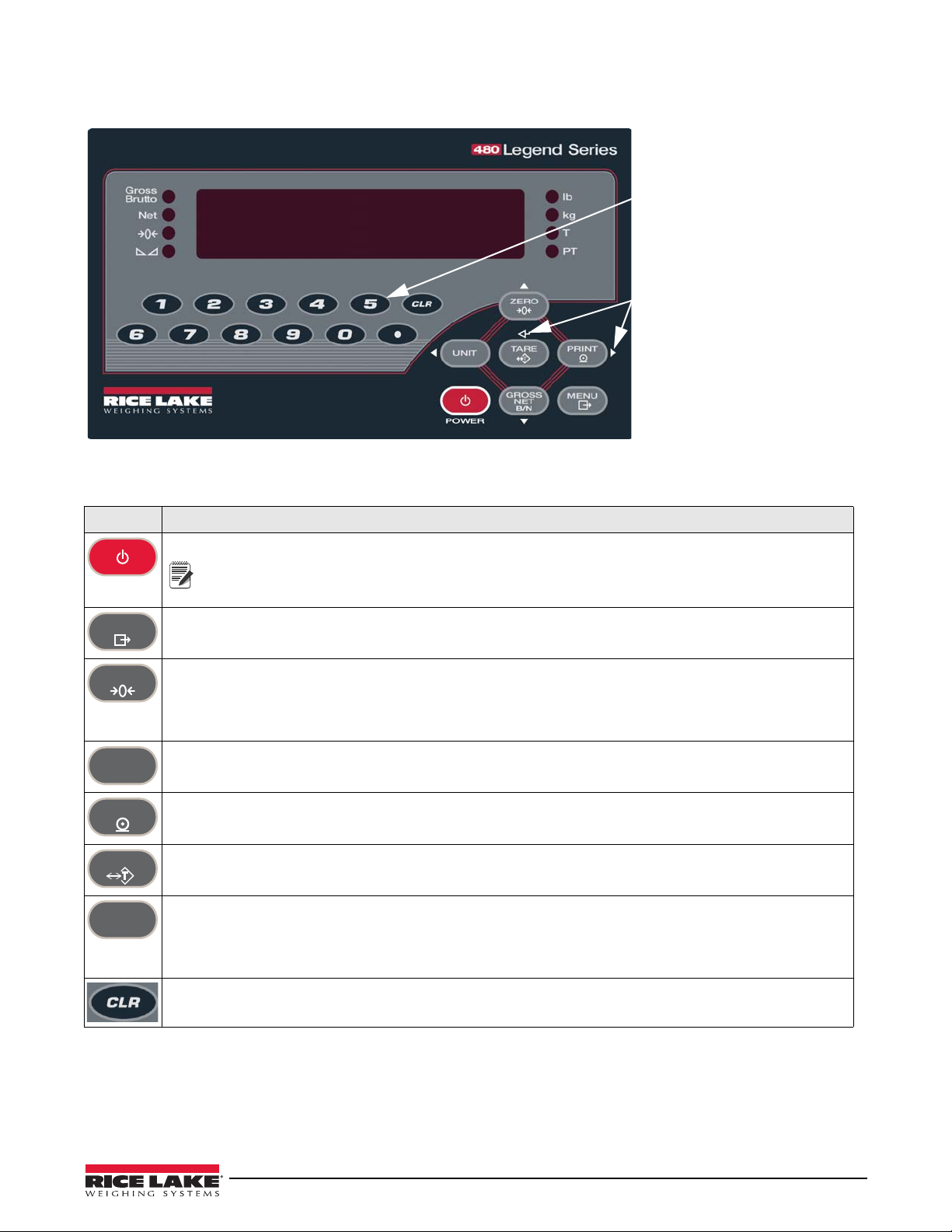
1.4 Front Panel Keypad
PRELIMINARY
The up, down, enter, left and right
arrows by the keys describe the
functions assigned in the
operating modes.
Keys are also used to navigate
through menus, select digits within
numeric values and increment/
decrement values.
Numeric Keypad – Enter numeric
values. See Section 1.7.1 on
page 5.
POWER
Note
MENU
ZERO
UNIT
PRINT
TARE
GROSS
NET
B/N
See Section 1.7 for information about using the front panel keys in configuration mode.
Figure 1-1. 480 Front Panel, Showing LED Annunciators and Key Functions (480Plus Shown)
1.5 Keypad Functions
Key Function
Turns t h e un i t on / off.
If power mode is set to manual, the Power button must be used to turn the unit on and off. If
power mode is set to auto, the unit will automatically power on when it’s plugged in and the only
way to turn it off is to unplug power. See Section 3.1.7.
The Menu key is used to access the User Setup menu.
Sets the current gross weight to zero, provided the amount of weight to be removed or added is within the
specified zero range and the scale is not in motion. The zero band is defaulted to two percent of full scale, but can
be configured for up to 100 percent of full scale.
Also used as a move up key to navigate to different menu levels or used to increment a number when editing a
value.
Switches the weight display to an alternate unit. The alternate unit is defined in the Configuration menu, and could
be kg, g, lb, oz, tn or t.
Also used as a scroll left key to navigate to different menus or to toggle to another digit when editing a value.
Sends on-demand print format out the serial port, provided the conditions for standstill are met. Print may be
displayed while printing.
Also used as a scroll right key to navigate to different menus or to toggle to another digit when editing a value.
Performs one of several predetermined Tare functions dependent on the mode of operation selected in the
TAREFN parameter. See Section 1.8.7 for more information on viewing stored tares.
Also acts as an enter key for numeric or parameter entry.
Switches the display mode from gross to net, or from net to gross. If a tare value has been entered or acquired,
the net value is the gross weight minus the tare.
Gross mode is shown by the Gross/Brutto annunciator; net mode is shown by the Net annunciator.
Also used as a move down key to navigate to different menu levels or to decrement a number when editing a
value.
During a numeric entry, sets the currently selected digit to 0, then selects one digit to the right.
Introduction 3
Page 11
1.6 LED Annunciators
PRINT
MENU
UNIT
POWER
TARE
GROSS
NET
B/N
ZERO
Move Right/Next
Move Up/Increment Value
Access User Setup
ENTER Value
Move Left/Previous
Move Down/Decrement Value
Power On/Off
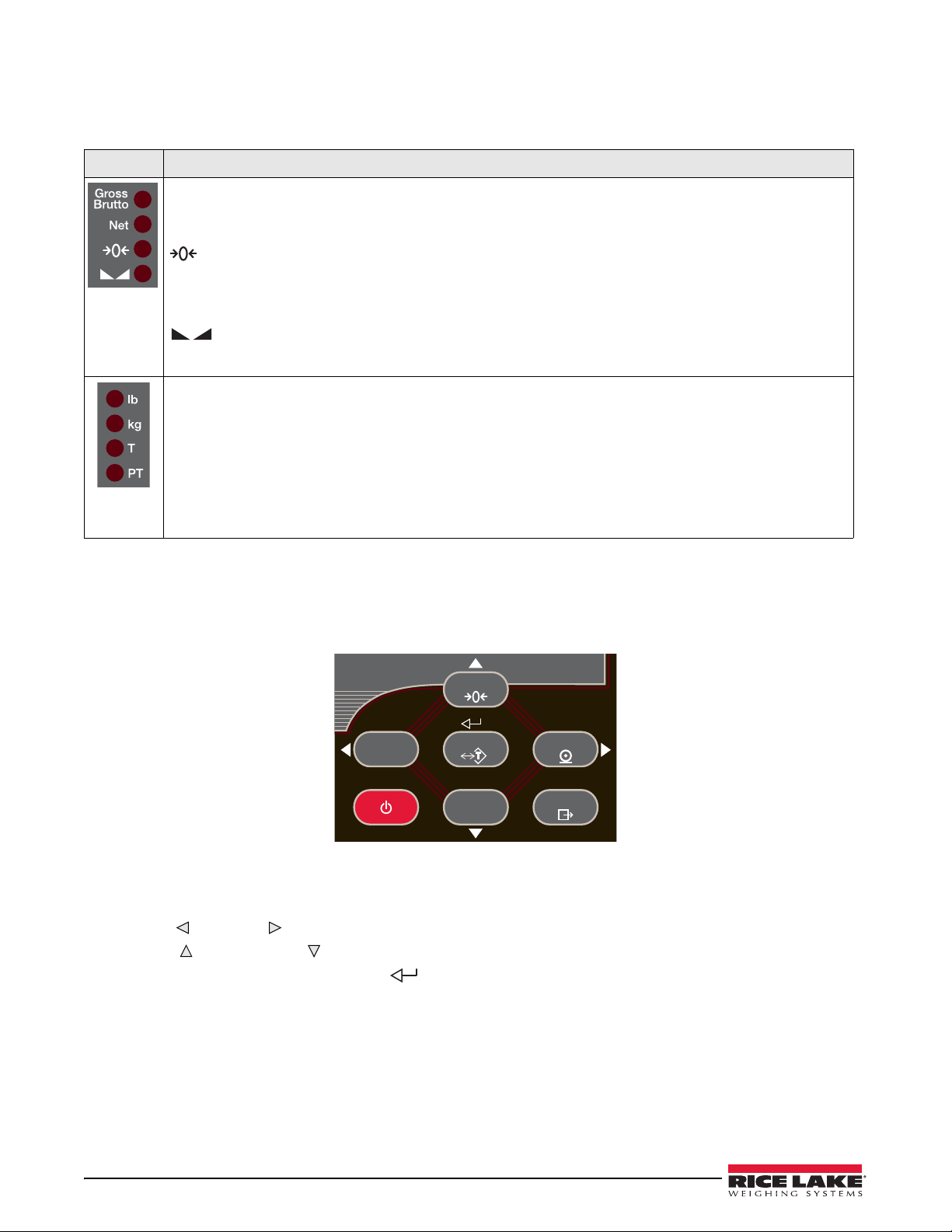
The 480 display uses a set of eight LED annunciators to provide additional information about the value being
displayed.
LED Description
Gross/Brutto LED
Gross weight display mode (or Brutto in OIML mode)
Net LED
Net weight display mode
Zero (Center of Zero) LED
The Center of Zero LED indicates that the current gross weight reading is within +/- 0.25 display divisions of the
acquired zero, or is within the center of zero band.
A display division is the resolution of the displayed weight value, or the smallest incremental increase or decrease
that can be displayed or printed.
Standstill LED
Scale is at standstill or within the specified motion band. Some operations, including zero, tare and print, can only
be done when the standstill LED is on.
lb/kg LED
Displays which unit of measure is being used.
lb and kg annunciators indicate the units associated with the displayed value: lb = pounds, kg = kilograms.
The displayed units can also be set to short tons (tn), metric tons (t), ounces (oz), grams (g) or none (no units
information displayed). The lb and kg LEDs function as primary and secondary units annunciators. If neither
primary nor secondary units are lb or kg, the lb annunciator is lit for primary units and kg is lit for secondary units.
T LED
Indicates that a push-button tare weight has been acquired and stored in memory.
PT LED
Indicates that a preset tare weight has been keyed in or entered and stored in memory.
Table 1-1. LED Annunciators
See Section 3.2.3 for more information about configuring primary and secondary display units.
1.7 Front Panel Navigation
Figure 1-2. Front Panel Key Functions
Four front panel keys are used as directional keys to navigate through the menus (see Figure 1-2).
•
Unit () and Print ( ) scroll left and right on the same menu level.
•
Zero () and Gross/Net ( ) move up and down to different menu levels.
•The
•The
Tare key serves as an enter key ( ) for selecting parameter values within the menus.
Menu key allows front panel access to user setup and configuration mode.
4 480 Legend Series
Page 12
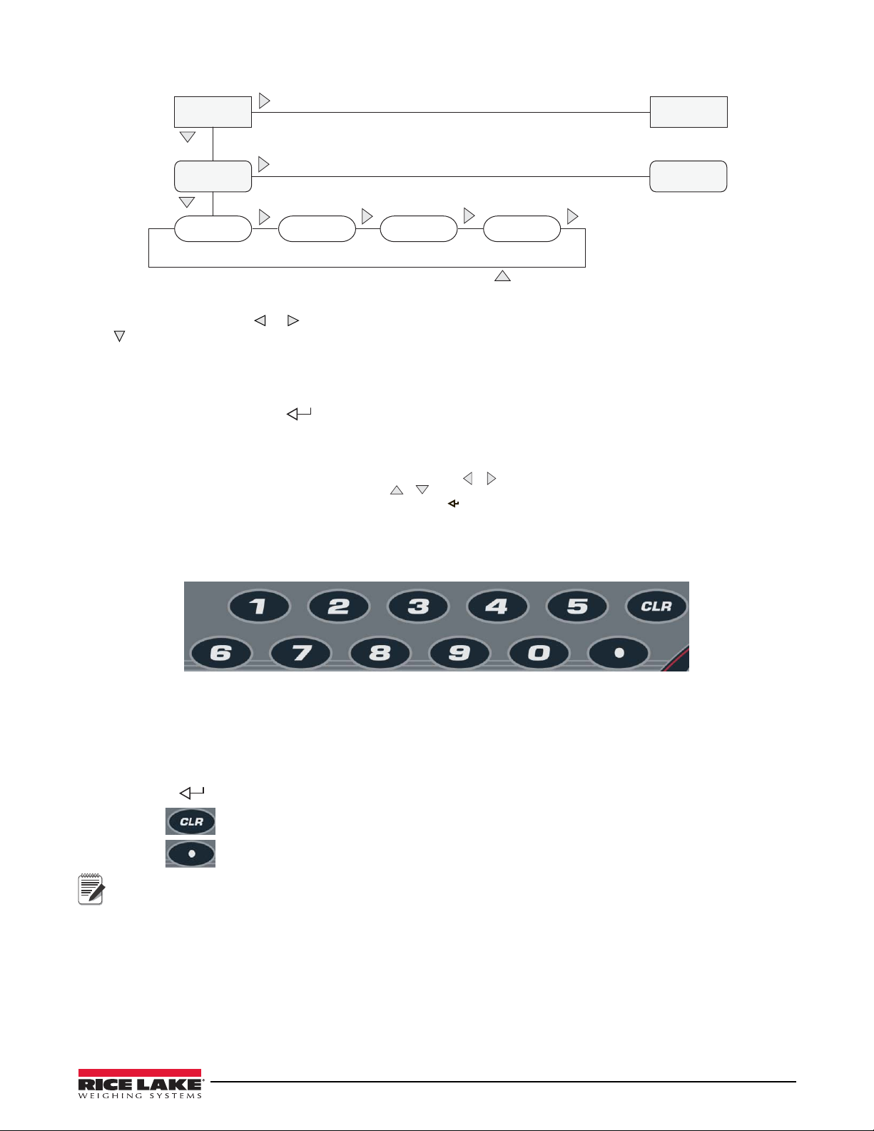
Navigating Through Levels
Default value Value Value
When moving through values below the first menu level, press to return to the level above.
Value
1st Level
Parameter
2nd Level
Parameter
1st Level
Parameter
2nd Level
Parameter
0 0 0 0 0 0
When editing numeric values, press or to change the
digit selected. Press or to increment or decrement the
value of the selected digit. Press to save the value entered
and return to the level above.
Note
Figure 1-3. Menu Navigation
To select a parameter, press or to scroll left or right until the desired menu group appears on the display, then
press to move down to the desired sub-menu or parameter. When moving through the menu parameters, the
present value appears first on the display.
Edit Parameter Values
To change a parameter value, scroll left or right to view the values for that parameter. When the desired value
appears on the display, press Tar e to select the value and move back up one level. T o edit numerical values, use
the navigation keys to select the digit and to increment or decrement the value.
Figure 1-4. Editing Procedure for Numeric Values
1.7.1 Numeric Keypad - Editing Procedure for Numeric Values (480 Plus Only)
Figure 1-5. Numeric Keypad for the 480Plus
With the numeric keypad option, numeric values can be edited with the numbers on the keypad rather than using
the navigation arrows. Numeric keys are functional only if the display is prompting for an input with a flashing
digit.
1. When editing numeric values, insert the required value using the numeric keypad.
2. Press
Tare to save the value entered and return to the level above.
• Press to set the currently selected digit to 0.
• Press to enter a decimal point.
When editing fractional numeric values, the decimal point must be positioned in accordance with the primary
units formatting, otherwise the keyed number may be rejected by the software.
Introduction 5
Page 13
1.8 Indicator Operations
MENU
Note
ZERO
UNIT
TARE
Basic 480 operations are summarized below.
1.8.1 Menu
Press , Menu will be displayed.
Press , then or to select the following parameters.
• Audit Trail (See Section 1.8.10)
• Display T are (See Section 1.8.7)
• Unit ID (See Section 1.8.11)
• Accumulator (See Section 1.8.12)
• Time and Date (See Section 1.8.13)
• Setpoints (See Section 1.8.14)
• Serial (See Section 3.1.2)
• Print Formats (See Section 7.0)
• USB (See Section 9.8)
• Ethernet (See Section 9.9)
• Version (See Section 1.8.15)
• Miscellaneous (Power Option) (See Section 3.1.7)
See Section 3.1 for more information.
Press repeatedly to return to the weigh mode.
Menus may be password protected. See Section 1.8.16 to setup a password.
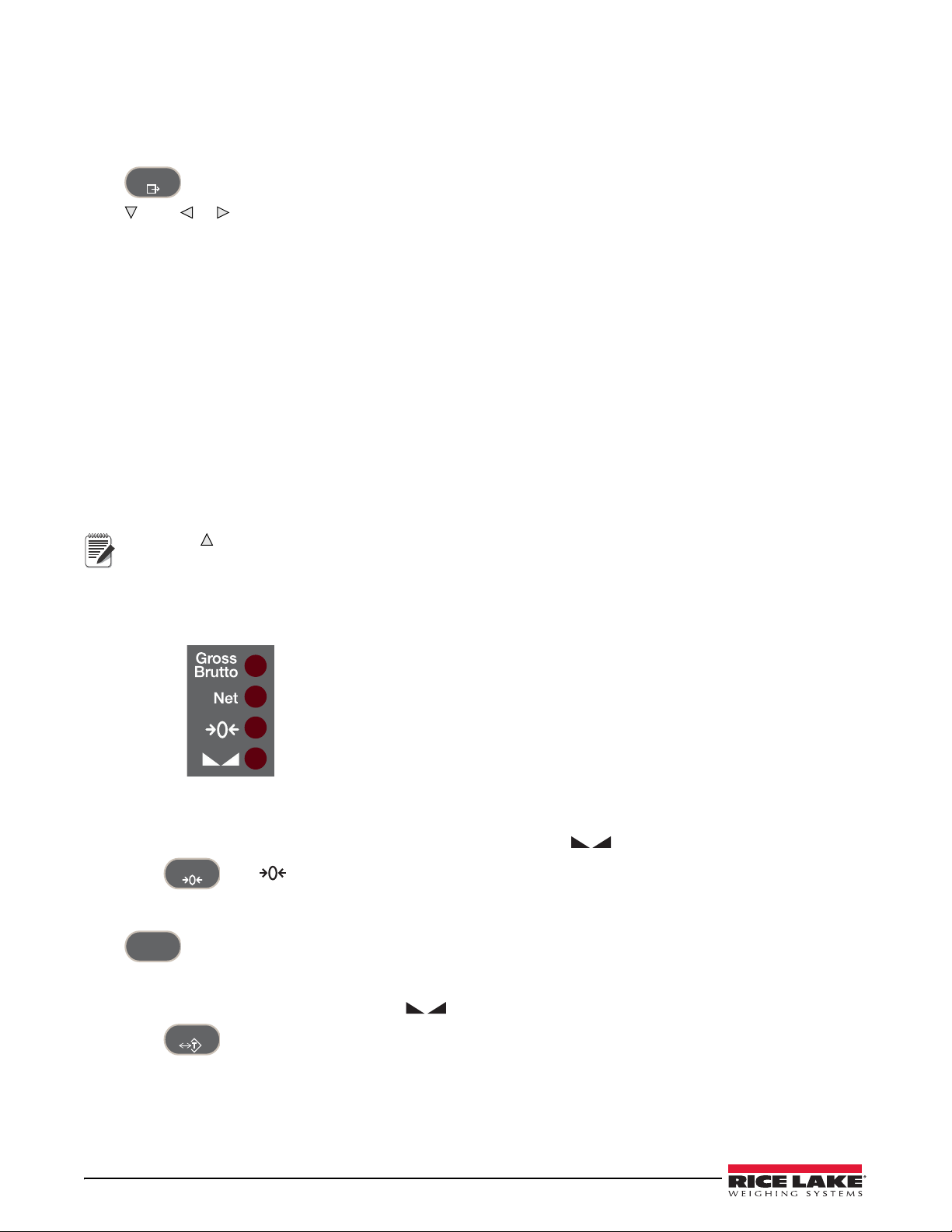
1.8.2 Status Lights While in Various Menus
Sub-menu levels are indicated by the LEDs as shown below.
First sub-menu level
Second sub-menu level
Third sub-menu level
Fourth sub-menu level
1.8.3 Zero Scale
1. In gross mode, remove all weight from the scale and wait for the LED to light.
2. Press . The LED lights to indicate the scale is zeroed.
1.8.4 Toggle Units
Press to toggle between primary and secondary units. The current unit LED will be lit.
1.8.5 Acquire Tare
1. Place container on scale and wait for the LED to light.
2. Press to acquire the tare weight of the container. Net weight is displayed and the
show the tare value was entered.
See Section 9.14 for Regulatory Mode Functions.
T LED lights to
6 480 Legend Series
Page 14
1.8.6 Preset Tare (Keyed Tare)
TARE
TARE
MENU
PRINT
PRINT
PRINT
PRINT
GROSS
NET
B/N
MENU
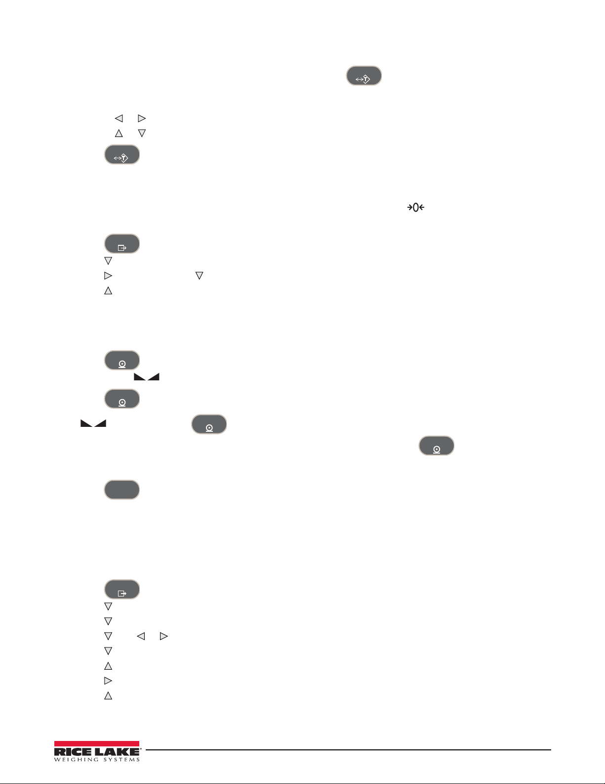
1. With the scale empty and display showing zero weight, press . 000000 is displayed with the focused
digit flashing.
2. Edit the value using the following method; or with the 480 PLUS, use the keypad. See Section 1.7 on page 4.
• Press or to select the digit.
• Press or to increment or decrement the value.
3. Press when the value is correct. The display will change to the Net mode and the
PT LED lights to
show the preset tare was entered.
1.8.7 Display Tare
When a stored tare value is displayed, the gross and net LEDs will be off and the will be lit.
To display a stored tare:
1. Press .
2. Press to
3. Press to
AUDIT.
TAR E and press .
4. Press repeatedly to return to weighing mode.
If there is no tare in the system,
0 will displayed and the Gross and Net LED will be off.
See Section 9.14 for more information pertaining to the regulatory mode of operation.
1.8.8 Print Ticket
1. Press to print either the gross or net format.
2. Wait for the LED to light.
3. Press to send data to the serial port.
If the LED is not lit and is pressed, the print action will take place only if the scale comes out of
motion within three seconds. If the scale stays in motion for over three seconds, the press is ignored.
1.8.9 Toggle Gross/Net Mode
1. Press to switch the display mode between gross and net. If a tare value has been entered or acquired,
the net value is the gross weight minus the tare.
Gross mode — Gross/Brutto LED is lit.
Net mode —
Net LED is lit.
1.8.10 View Audit Trail
See Section 3.1 on page 22 for audit trail settings.
1. Press .
2. Press to
3. Press . The audit trail
4. Press then or to
5. Press to view selected parameter.
6. Press twice to return to
7. Press to the audit trail
8. Press repeatedly to return to weighing mode.
AUDIT.
CALIB is displayed.
CNT, TIME or DATE.
CALIB.
CONFIG and repeat steps 5 and 6 to view configuration number.
Introduction 7
Page 15
1.8.11 Enter New Unit ID
MENU
TARE
MENU
TARE
TARE
Note
MENU
TARE
Note
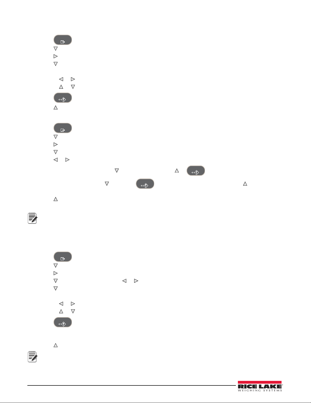
1. Press .
2. Press to
3. Press until display reads
AUDIT.
UNIT ID.
4. Press to view the current value.
5. Edit the value using the following method; or with the 480 PLUS, use the keypad. See Section 1.7 on page 4.
• Press or to select the digit.
• Press or to increment or decrement the value.
6. Press when the value is correct.
7. Press repeatedly to return to weighing mode.
1.8.12 Display Accumulator
1. Press .
2. Press to
3. Press until display reads
4. Press to display
5. Press or to select desired parameter (
•For
•To
selected parameter
6. Press repeatedly to return to weighing mode.
See Section 3.1 for the accumulator menu structure.
AUDIT.
ACCUM.
VIEW.
VIEW, TIME, DATE, PRINT, CLR Y).
VIEW, TIME or DATE, press to view the value. Press or to return to selected parameter.
PRINT or CLEAR, press , then press to print or clear the accumulator. Press to return to
If the accumulated value exceeds 999999, display shows EE ACC. The value will still be correct and will print
correctly up to 1,000,000,000.
1.8.13 Display or Change Time and Date
To set the date and time:
1. Press .
2. Press to
3. Press until display reads
4. Press and select time or date with or .
5. Press to view the current setting.
6. To edit the value of the time, in 24 hour or 12 hour format (hh.mm.ss), use the following method.
• Press or to select hours, minutes, or seconds – the selected value will be flashing
• Press or to increment or decrement the value.
7. Press when the value is correct.
Use the same procedure to enter the date in the same format configured for the indicator.
See Section 3.2.5 for available formats.
8. Press repeatedly to return to weighing mode.
AUDIT.
TIMDAT (T ime/ Date).
The time and date are backed up with an internal battery. If the main power is interrupted, time and date will
not be lost.
When in 12 hour format, the PT LED indicates pm setting.
8 480 Legend Series
Page 16
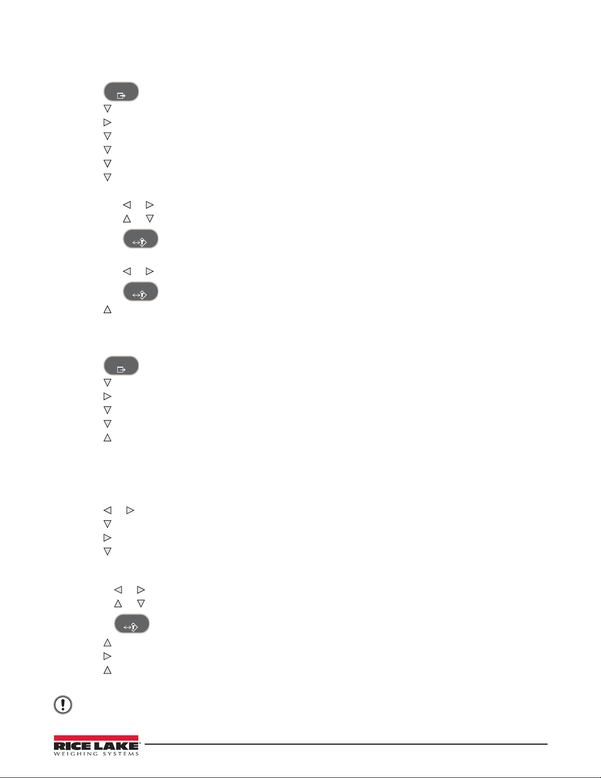
1.8.14 Display, Edit and Set Setpoint Value
MENU
TARE
TARE
MENU
TARE
Important
See Section 8.0 on page 59 more information.
1. Press .
2. Press to AUDIT.
3. Press until display reads
4. Press and navigate across to desired setpoint number (1-8).
5. Press and navigate across to select
6. Press and navigate across to select
7. Press to view and edit the value.
• To edit Value, use the following method; or with the 480 PLUS, use the keypad. See Section 1.7 on page 4.
- Press or to select the digit.
- Press or to increment or decrement the value.
- Press when the value is correct.
SETPNT.
USER.
VALUE or ENABLE.
• To edit
- Press or to select
ENABLE:
On/Off.
- Press when the value is correct.
8. Press repeatedly to return to weighing mode.
See Section 3.1.1 for the
SETPNT menu layout.
1.8.15 View Firmware Version
1. Press .
2. Press .
3. Press until display reads
4. Press .
AUDIT is displayed.
VERS.
FIRMW is displayed.
5. Press to view version.
6. Press repeatedly to return to weighing mode.
1.8.16 Enter User Password
1. Remove the setup switch access screw from the back of the enclosure. See Figure 2-1 on page 10.
2. Insert a non-conductive tool into the access hole and press the configuration switch. Indicator display
changes to show
3. Press or until
4. Press .
CNFG is displayed.
5. Press to
6. Press .
000000 is displayed.
7. To edit the password, use the following method; or with the 480 PLUS, use the keypad. See Section 1.7 on
page 4
• Press or to select the digit.
• Press or to increment or decrement the value.
CONFIG.
PAS WRD is displayed.
USER.
• Press when the value is correct.
8. Press to return to
9. Press to
CONFIG.
PASWRD.
10. Press to return to weighing mode.
When entering a user function, the operator will now be required to enter the password.
Enter 999999 to reset password, this will also reset the configuration back to default values.
Introduction 9
Page 17
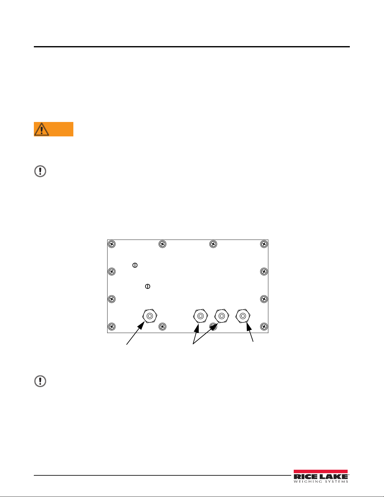
2.0 Installation
WARNING
Important
Setup switch
access screw
Load cell cable
cord grip (open)
Communications
access cord grip
(plugged)
Power cord
Back of indicator
Important
2.1 Unpacking
Immediately after unpacking, visually inspect the 480 to ensure all components are included and undamaged . The
shipping carton should contain the indicator, this manual, and a parts kit. If any parts were damaged in shipment,
notify Rice Lake Weighing Systems and the shipper immediately.
See Section 2.8 on page 18 for parts kit contents.
2.2 Enclosure Disassembly
The indicator enclosure must be opened to connect the scale load cell cable and any other interface connection.
Before opening the unit, ensure the power cord is disconnected from the power outlet.
Ensure power to the indicator is disconnected, then place the indicator face-down on an anti-static work mat.
Remove the screws that hold the backplate to the enclosure body. Then lift the backplate away from the enclosure
and turn it over to access boards.
The display cable will still be attached. Be careful when lifting and turning over the backplate so it does
not become damaged or dislodged.
2.3 Cable Connections
The 480 provides four cord grips for cabling into the indicator: one for the power cord, three to accommodate load
cell, communications, digital inputs and outputs, and analog output cables. Two of the three free cord grips come
with a plug installed to prevent moisture from entering the enclosure. Depending on the application, remove the
plug from any cord grip that will be used and install cables as required. Figure 2-1 shows the recommended
assignments for the 480 cord grips.
10 480 Legend Series
Figure 2-1. Recommended Cord Grip Assignments
When installing cords through cord grips, ensure the cord grip is tightened snuggly to prevent moisture
from entering the enclosure.
Page 18
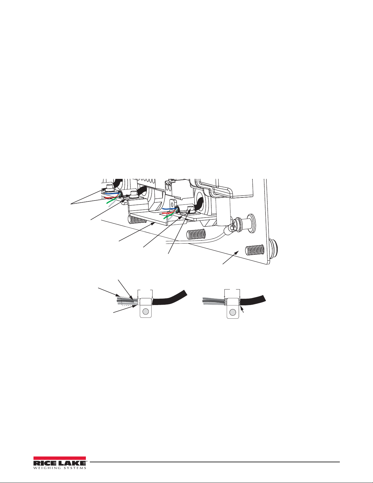
2.3.1 Cable Grounding
Grounding
clamp
Braid
Braided Cable
Cut insulation here
Foil Insulated Wire
Silver
side out
Shield wire (cut)
Cut insulation here
for foil sheilded cables
Length of foil before
folding back on
cable insulation
Grounding
bracket
Grounding
clamp
480 Indicator
back panel
Ground
clamp screw
Ground
clamp screw
Except for the power cord, all cables routed through the cord grips should be grounded against the indicator
enclosure. Do the following to ground shielded cables:
• Use the ground clamp screws to install grounding clamps on the grounding bar. Do not tighten screws yet.
There is a larger clamp available in the parts kit; the larger clamp is for a cable diameter of 0.25 inch, the
smaller clamp is for a cable diameter of 0.18 inch
• Route cables through cord grips and grounding clamps to determine cable lengths required to reach cable
connectors. Mark cables to remove insulation and shield as described below:
• For cables with foil shielding, strip insulation and foil from the cable 1/2
grounding clamp (see Figure 2-2). Fold the foil shield back on the cable where the cable passes through
the clamp. Ensure silver (conductiv e) side of foil is turned outward for contact with the grounding clamp.
• For cables with braided shielding, strip cable insulation and braided shield from a point just past the
grounding clamp. Strip another 1/2 inch (15 mm) of insulation to only expose the braid where the cable
passes through the clamp (see Figure 2-2).
• For load cell cables, cut the shield wire just past the grounding clamp. Shield wire function is provided
by contact between the cable shield and the grounding clamp.
• Route stripped cables through cord grips and grounding clamps. Ensure shields contact grounding
clamps as shown in Figure 2-2. Tighten ground clamp screws.
inch (15 mm) past the
Figure 2-2. Grounding Clamp Attachment for Foil-Shielded and Braided Cabling
Cable Connections 11
Page 19
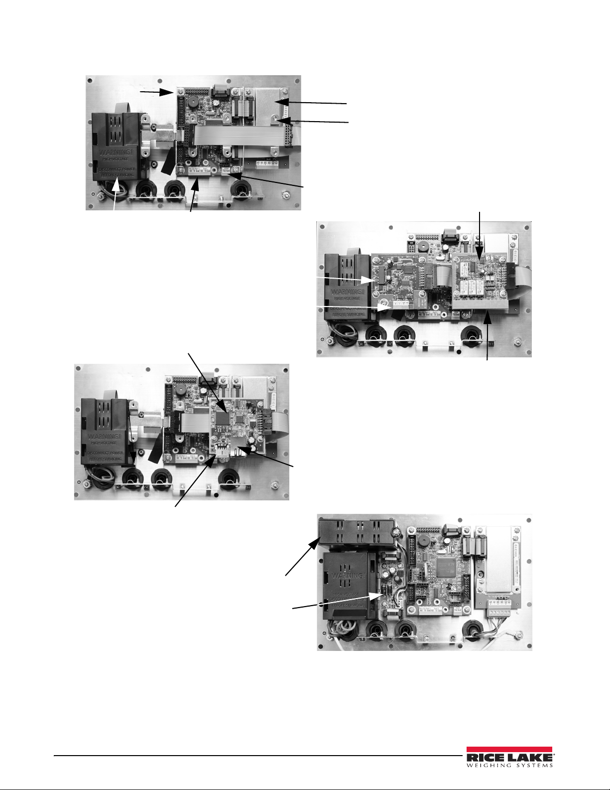
2.3.2 Wiring
Relay (DIO) Board
Analog Output Board
A/D Board
CPU Board
Power Supply
Analog Output
Connection
1 I/O 15
20mA Comm 2
Connection
Comm 1 & 2
Connection
Option Card Bracket
Ethernet/USB Board
Battery and Battery Holder
Analog Output and Relay Board Options
Power Supply, CPU and A/D Board
Ethernet/USB Board Option
Battery Option
Charger Board
Digital I/O Connection
Ethernet RJ45 Plug
USB 5-Pin Plug
12 480 Legend Series
Figure 2-3. 480 Board Options
Page 20
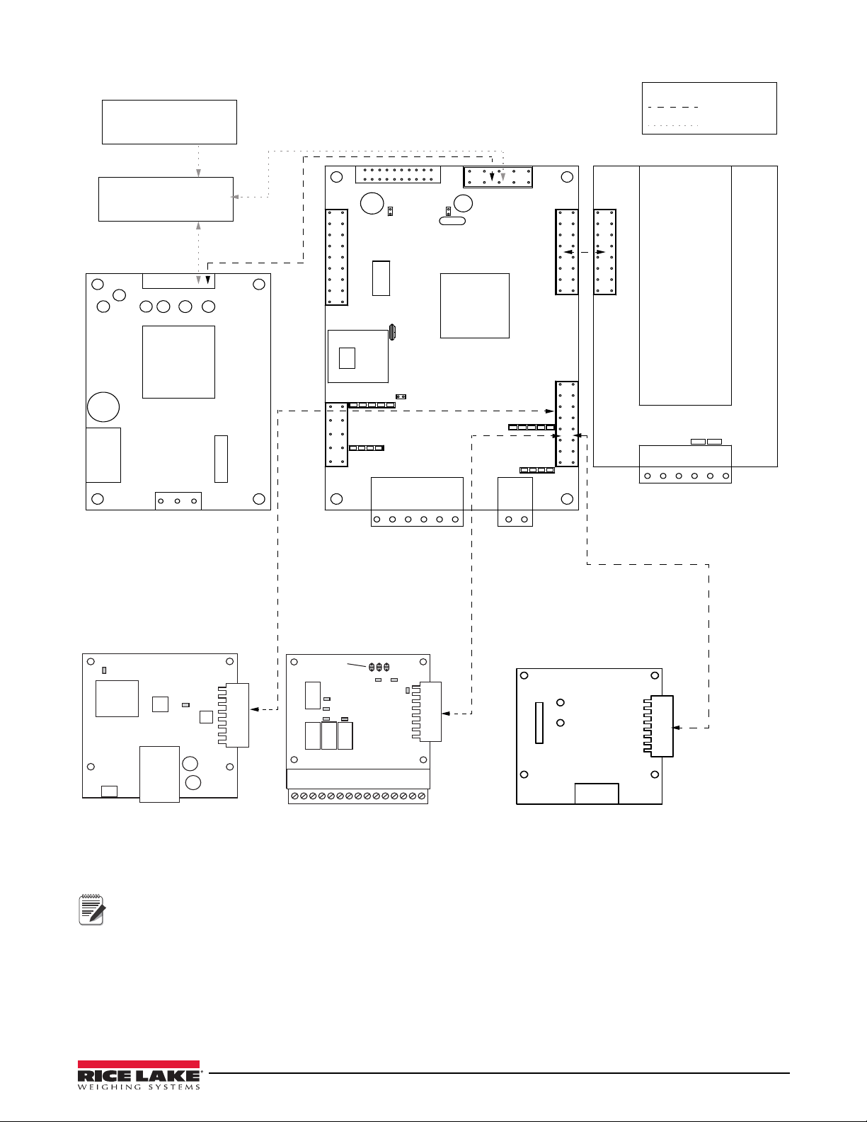
20mA_Out
RXD1
TXD1
GND
RXD2
TXD2
GND
GND
Sig+
SIG-
SEN+
SEN-
EXC+
EXC-
Load Cell Connection
RS-232
Connection
20mA
Connection
L
GND
N
Power Supply
CPU Board PN 131318
A/D Board PN 131319
Power Supply
PN 131316
Analog Output
PN 131341
Relay Board
PN 131342
J2
J1
J2
J13
J17
J5
J6
J15
J16
J14
J7 to display board
J2
J10
R1_NC
R1_C
R1_NO
R2_C
R2_NO
R3_C
R3_NO
R4_C
R4_NO
IN-
IN1+
IN-
IN2+
+5V_OUT
GND
I_OUT
RETURN
V_OUT
RETURN
Analog Output Terminal
I/O Terminal
J3 J4
Sense Jumpers
Ethernet/USB Board
PN 164600
Heartbeat
LED
LED1
Activity
USB
5-Pin Plug
J2
RJ45
Ethernet
Jack
J1
J4
RL4_ON
RL1_ON
RL2_ON RL3_ON
IN1
IN2
+5V
OUT
RL4
RL1
RL2
RL3
J2
Mode Select
Jumpers
JMP2
JMP3 JMP1
A2 A1 A0
J3
Battery Charger
PN 131317
Battery
PN 131323
Standard
Option
Key
J9
Battery and Battery Charger are optional.
Analog, Ethernet/USB and Relay boards require an option card bracket (PN131340) for mounting.
Relay Board Information:
To use outputs 1-4 and inputs 1-2, short jumper A1 (JP2)
To use outputs 5-8 and inputs 3-4, short jumpers A0 (JP1) and A1 (JP2)
Output relay rating of relay 2 AMPS at 30 VDC dry contact relay closure
Digital Input is opto-isolated, activated with 5-24VDC.
Note
Figure 2-4. Wiring Diagram
Cable Connections 13
Page 21

2.4 Battery Operation
Note
The 480 can be equipped with an optional internal Lithium-Ion battery to provide up to:
• 18 hours of continuous use (single load cell, 350 ohms, no options)
• 15 hours of continuous use (four load cell, 350 ohms, no options)
When operated on AC power, the internal battery is automatically charged by means of an internal battery charger circuit.
Battery life depends on several factors, including number of load cells, frequency of use, options installed,
temperature and other accessories being used. Battery charge time is approximately 16 hours to 100 percent.
To extend battery life, the indicator features a sleep mode that allows the indicator to go into a low power mode
while it’s operating on battery power. See Section 9.6 on page 65 for more information about the sleep mode.
When installing a 480 with a battery option, it is recommended that the CPU board jumper 4 be removed.
Removing jumper 4 will maximize the life of the battery when the indicator is turned off due to reduced
standby current. See the Power parameter in Section 3-8 on page 31 for more information.
When the Standby parameter is set to any setting other than NONE, any key press will work to wake the
indicator from standby.
14 480 Legend Series
Page 22

2.5 Option Card Installation
Note
Note
Use the following instructions to install or replace the Analog Output Module (PN 131341), Relay Board (PN
131342) or Ethernet/USB option card (PN 164600).
1. Disconnect p
ower to the indicator.
2. Remove backplate as described in Section 2.2 on page 10.
3. If not already in place, install an option card bracket (PN 131340). See Figure 2-3.
4. Mount the analog output module, relay card or the Ethernet/USB option card on the option card bracket. See
Figure 2-3. The Ethernet/USB option card has to be installed on the option card bracket above the A/D card,
not in the location near the power supply.
5. Connect the option card ribbon to the option card(s).
6. Connect the option card ribbon to J9 on the CPU board.
7. Connect output cables, as needed, to the option card(s).
Either option card position can be used for the Analog Output Module, or the Relay Card.
The Ethernet/USB Option Card must be installed in the location above the A/D Card, not next to the Power
Supply.
2.6 Board Removal
If you must remove any 480 board, use the following procedure:
1. Disconnect power to the indicator.
2. Remove backplate as described in Section 2.2 on p age 10.
3. Disconnect all cables from the board.
4. Label connections for re-installation of board.
5. Remove the four screws from the board, then lift the board off the backplate.
To install a board, reverse the above procedure. Be sure to reinstall cable ties to secure all cables inside the
indicator enclosure.
When removing lower boards, the upper boards and option bracket, if installed, will need to be removed first.
Option Card Installation 15
Page 23
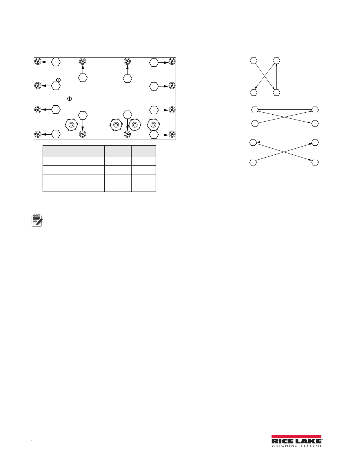
2.7 Enclosure Reassembly
1
2
4
3
11
5
7
9
6
8
12
10
Step 1.
Torque 1-4 in the order shown
1 3
4 2
Step 2.
Torque 5-8 in the order shown
7 6
5 8
Step 3.
Torque 9-12 in the order shown
11 10
9 12
To rq u e in-lb Nm
Backplate screws
10 1
Cable Glands
22 2.5
Cable Gland Caps
13.3 1.5
Vent
5-7 0.6-0.8
Table 2-1. Torque Values
Note
Once cabling is complete, position the backplate over the enclosure and reinstall the backplate screws. Use the
torque pattern shown in Figure 2-5 to prevent distorting the backplate gasket. Torque screws to 10 in-lb (1 N-m).
Figure 2-5. 480 Enclosure Backplate
Torqued screws may become less tight as the gasket is compressed during the torque pattern; a second
torque is required using the same pattern and torque value.
16 480 Legend Series
Page 24
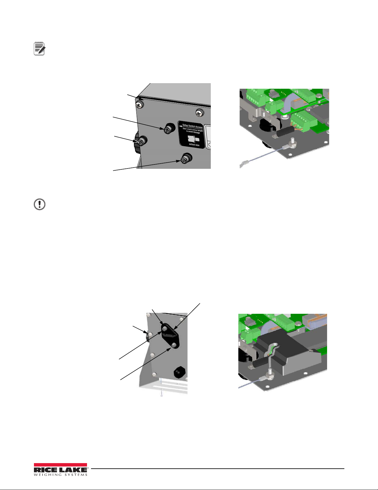
2.7.1 Seal the Indicator (Optional)
Note
Without A/D cover
11 - Screw, Pan Cross Head
8-32NC
1 - Screw, 8-32 drilled
fillister head
1 - Screw, 8-32 drilled
fillister head
1 - Screw, 1/4'' drilled
fillister head
Important
With A/D cover
12 - Screw, Pan Cross Head
8-32NC
Calibration Cover
for Hardware Sealing
Setup Switch
Access
1 - Screw, 4-40 drilled
fillister head
1 - Screw, 8-32 drilled
fillister head
For access to configuration parameters, the setup switch must be pressed.
Prevents Service Access
Insert a lead wire seal through three fillister screws. This prevents access to the electronics, electrical contacts and
Legal for Trade configuration parameters.
Figure 2-6. Sealing the Indicator to Prevent Access
Only use the 1/4 inch screw in the top hole for sealing, using the longer one will damage the CPU board.
Allows Service Access – Optional
The calibration cover is used for inserting a lead wire seal through both fillister screws and the plastic cover. The
cover allows access to the electronics and electrical contacts, while preventing access into Legal for Trade
configuration parameters.
There is an alternative cover over the A/D to ensure the A/D and load cell connection cannot be changed after the
unit is sealed. This cover is secured to the A/D with the bottom fillister screw in the calibration cover.
There is also an audit trail counter to track calibration and configuration changes made to legally relevant
parameters.
Place the calibration cover on the backplate and secure with the existing fillister head screws and o-rings to seal the
indicator for Legal for Trade approval.
Figure 2-7. Sealing the Indicator to Allow Access Option
Enclosure Reassembly 17
Page 25
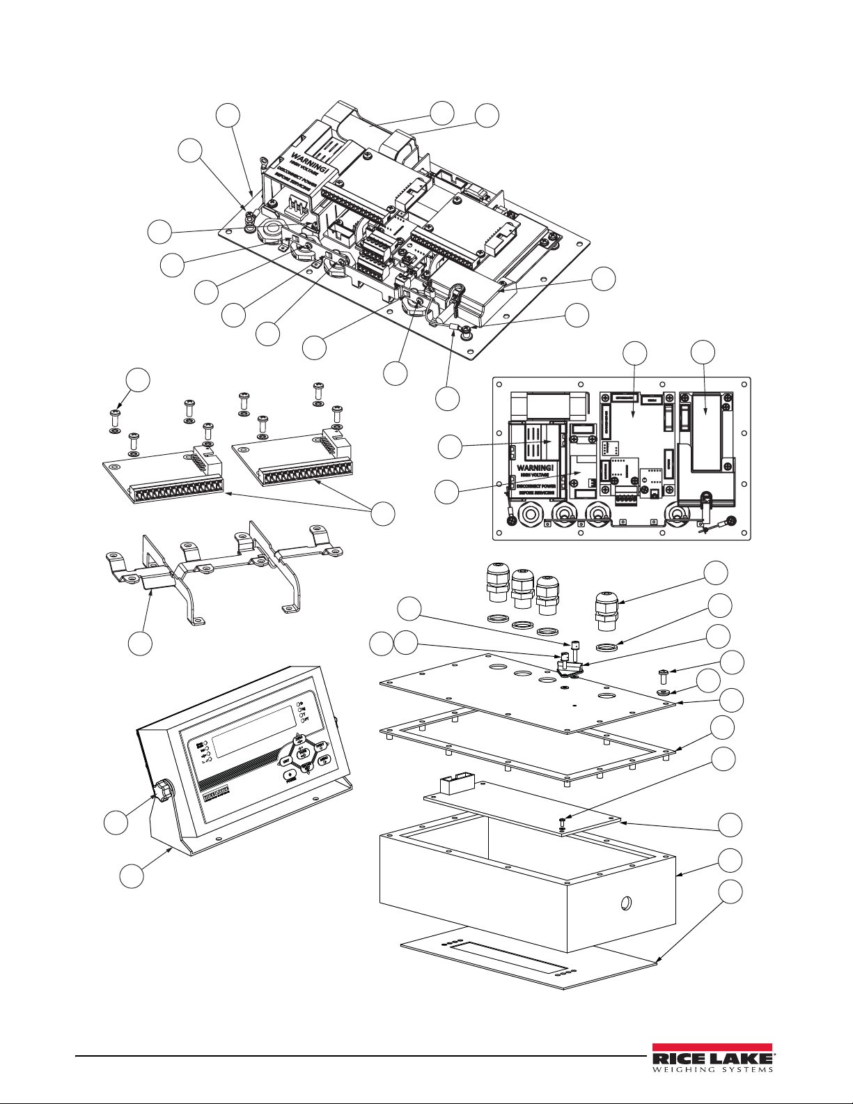
2.8 Replacement Parts
4
1
1
2
3
7
7
7
8
4
9
19
16
18
17
6
10
23
25
3
20
21
27
15
14
13
Representation only.
Actual boards may
look dierent.
22
24
31
30
6
6
11
11
11
29
28
32
18 480 Legend Series
Figure 2-8. Replacement Parts
Page 26
Item
No.
Part No. Description QTY
1 131322 Battery bracket (Opt) 1
2 131323 Battery, rechargeable (Opt) 1
3 131321 Backplate, back plane base 1
4 14626 Nut, Kep 8-32 NC Hex 4
6 131328 Screw, 4-40 x 0.3125 1
7 131333 Ground clamp, 3/16 Ø 3
164580 Ground Clamp, 1/4 Ø 1
8 131334 Ground wire, insulated 2
9 131340 Bracket for option module 1
10 131341 Analog output, 0-10VDC, 4-20 mA 1
131342 Relay board, 2 inputs, 4 relays 1
164600 USB/Ethernet TCP/IP 1
11 22085 Screw, 4-40 x 0.188 8
13 131345 Overlay, 480 6-key 1
159612 Overlay, 480Plus, numeric keypad 1
14 131343 Enclosure, front 1
15 131346 Display board, LED 7 segment 1
16 131316 Power supply, 85-265 VAC 1
17 131317 Battery charger, VDC to VDC (Opt) 1
18 131318 Board assembly, CPU 1
19 131319 Board, assembly, A/D 1
20 131324 Screw, 4-40 drilled fillister head 1
21 131325 Screw, 8-32 drilled fillister head 1
22 131335 O-ring 2
23 15626 Cord-grip, PG9 4
24 30375 Seal ring, nylon PG9 4
25 131336 Calibration cover (Opt) 1
27 131344 Gasket, backplate 1
28 14862 Screw, 8-32NC x 3/8 4
29 45042 Washer, bonded sealing 8 x 0.375 4
30 164912 Tilt Stand 1
Table 2-2. Parts List
31 164577 Knob & washer, M6 thread 2
32 164579 Cover, A/D Sealing (optional) 1
164604 Ethernet cable with cord grip, 6 ft 1
164602 USB Cable, Type A Female, 20 cm 1
167707 USB Cable, Type A Male, 200 cm 1
167708 USB Cable, Type B Male, 200 cm 1
88733 Vent, breather vent 1
88734 Nut, breather vent 1
103462 2-position screw terminal 1
76513 4-position screw terminal 1
76514 6-position screw terminal 2
157223 15-position screw terminal 1
155230 Ribbon cable CPU to display 1
155231 Ribbon cable CPU to A/D 1
155232 Ribbon cable PS to CPU Board 1
155233 Ribbon cable CPU to Option 1
155234 Pwr cord 115VAC, NEMA 5-15 plug 1
155235 Pwr cord 230VAC, Euro CEE 7/7 1
Part No. Description Qty
94422 Label, Capacity 1
53374 Label, Annunicators 1
14862 Screw, 8-32NCx3/8 8
45042 Washer,Bonded Sealing #8 x 0.375 8
76514 Conn, 6-Pin for LC and RS-232 ports 2
103462 Conn, 2- Pin for 20 mA port 1
131325 Screw, Fillister 8-32NC x ¼ 1
131320 Screw, Fillister 8-32NC x ½ 1
Table 2-3. Parts Kit (PN 131314)
Item
No.
Part No. Description QTY
Table 2-2. Parts List
Replacement Parts 19
Page 27

3.0 Configuration
Note
There are two types of configuration parameters in the 480: Legal for Trade configuration and non-legal
configuration (or operator param eters). Legal for Trade configuration requires pressing the setup switch (see
Section 3.2). Non-legal configuration parameters do not require pressing the setup switch, but may be password
protected.
The following sections provide graphic representations of the 480 menu structures. In the actual menu structure,
the settings chosen under each parameter are arranged horizontally. To save page space, menu choices are shown in
vertical columns. The factory default setting appears at the top of each column in bold type. Most menu diagrams
are accompanied by a table that describes all parameters and parameter values associated with that menu.
Parameter level is indicated by the left LED position, levels 1-4.
See Section 1.7 on page 4 for navig ation methods.
A menu map is provided on the following page for reference.
20 480 Legend Series
Page 28
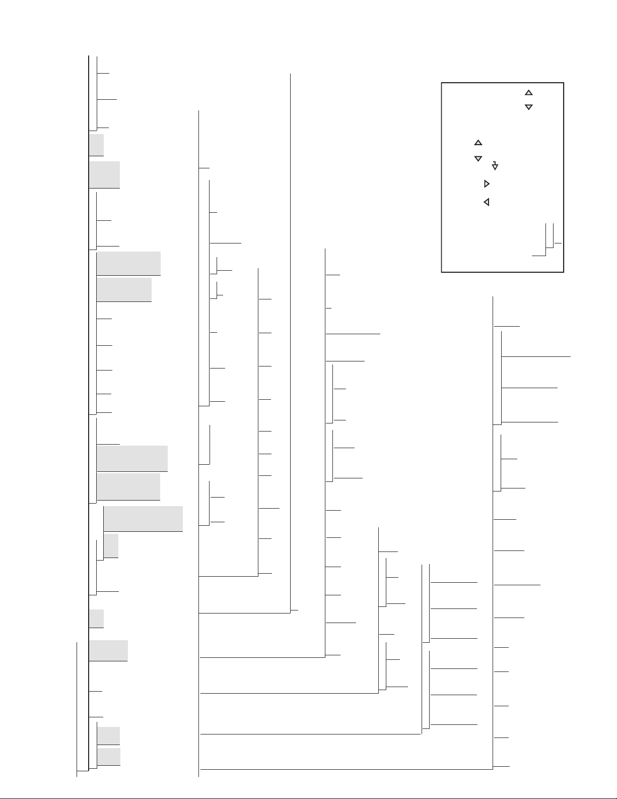
Shaded Menus
Indicate lower
level values,
selections or
settings are
not shown.
SAVE LOAD
USBMEM
ADTEST NWGMNT WGMNST DIGIN DIGOUT ALGOUT DEFLT
999999TOTAL
OVRCAP
Raw A/D
Counts
1-4 1-4 0
25%
50%
100%
VIEW
HI
LOW
Press G/N
TEST
CNFG USER
Enter
Value
Enter
Value
PASWRD
SOURCE OFFSET ERRACT MIN
GROSS
NET
0%
20%
FULLSC
HOLD
ZEROSC
MAX MINNEG
NO
YES
Enter
Value
MAXNEG
Enter
Value
NO
YES
TWZERO TWSPAN OUTPUT
Enter
Value
Enter
Value
CURENT
VOLTAGE
ALGOUT
DIGIN1-4
OFF ZERO TARE NT-GRS UNITS DPSTAR PRINT CLRCN KBDLOC HOLD CLRTAR ACCUM CLRACC BATSTR BATSTP BATRES BATPUS BATRUN NET GROSS PRI SEC
DIG IN
PWRUPM
GO
DELAY
REGULA
NTEP
OIML
CANADA
NONE
CONSNU
0-
999999
CONSTU
0-
999999
ACCUM
OFF
ON
RTZGRD
Enter
Value
DATE
DATFMT
MMDDYY
DDMMYY
YYMMDD
YYDDMM
DATSEP
SLASH
DASH
SEMI
TIME
TIMFMT
24 HOUR
12 HOUR
TIMSEP
COLON
COMMA
SLEEP
NEVER
1 MIN
2 MIN
5 MIN
10 MIN
STDBY
1 SEC
2 SEC
3SEC
5 SEC
10 SEC
60 SEC
OFF
WGTHRH
0-FS
DDTHRH
0-
999999
PROGRM
GRADS ZTRKBN ZRANGE INIZR MOTBN OVRLOA DSPRAT SMPRAT DIGFIL TAREFN
Enter
Value
Enter
Value
Enter
Value
Enter
Value
Enter
Value
FS-2%
FS-1D
FS-9D
FS
ADPFIL
BOTH
NOTARE
PBTARE
KEYED
0.10 SEC
0.25 SEC
0.50 SEC
0.75 SEC
1.00 SEC
NONE
5 HZ
10 HZ
20 HZ
40 HZ
ROLFIL
ADPFIL
ROLFIL
OFF
LIGHT
MEDIUM
HEAVY
Enter
Value
AFSENS AFTHRH
2481632641
8OUT
16OUT
32OUT
64OUT
128OUT
2OUT
4OUT
RFSTG1-3 RFSENS
RFTHRH
NONE
2 dd
5 dd
10 dd
20 dd
50 dd
100 dd
200 dd
250 dd
CONFIG
(Press Menu Key to enter, also available when Configuration switch is pressed)
SETPNTTARE
AUDIT
UNITID
TIMDAT
TIME
DATE
ACCUM
SERIAL
CALIB CONFIG
Enter
Tare
Enter
ID
VIEW
TIME
DATE
PRINT
CLR Y
CNT
TIME
DATE
CNT
TIME
DATE
OFF
AUTO
MANUAL
BATCHG
USER SUPVSR
VALUE
ENABLE
KIND
TRIP
WAITSS
PUSHPR
PUSHAC
PUSHTR
DIGOUT
BATSEQ
PREACT
HYSTER
SETPT1-8
COM-1 COM-2 STREAM
TRIGER
BAUD
BITS
SBITS
TERMIN
EOLDLY
ECHO
PRNMSG
TRIGER
BAUD
BITS
SBITS
TERMIN
EOLDLY
ECHO
PRNMSG
STRUR
NONE
LOCAL
REMOTE
POWER BKLGHT BAT
PFRMAT MISCVERS
USB
MANUAL
AUTO
OFFONAUTO
GFMT
NFMT
ACCFMT
SPFMT
FIRMW
LR
ETHNET
ON
OFF
DHCP
IPADRS
Enter
Value
SERVER
TRIGER
TIMOUT
TERMIN
SFMT
PORT
EOLDLY
ECHO
CLIENT
TRIGER
TIMOUT
TERMIN
SFMT
PORT
RMOTIP
EOLDLY
ECHO
NETMSK
Enter
Value
DFTGWY
Enter
Value
MAC
View
Only
DEVICE
HOSTPC
DRIVE
PRINTR
TRIGER
DEMAND
COMAND
BAT LEVEL
MENU
MENU
(Press Configuration Switch to enter)
See Menu Above
WZERO WVAL WSPAN REZERO
CAL
Enter
Value
EDIT
Press
Enter
“ENTER”
CAL EDIT
Press
Enter
“ENTER”
CALIBR
Enter
Value
Enter
Value
Press
Enter
“ZERO”
PRIMAR SECNDR
DECPNT DSPDIV UNITS
888888
8.88888
88.8888
888.888
8888.88
88888.8
1d2d5d
10d
20d
50d
LBKGOZTNT
G
DECPNT DSPDIV UNITS
888888
8.88888
88.8888
888.888
8888.88
88888.8
1d2d5d
10d
20d
50d
LBKGOZTNT
G
FORMAT
Level 2
Level 3
Level 4
Level 1
Level Layout
0 0 0 0 0 0
When editing numeric values, press or to change the
digit selected. Press or to increment or decrement the
value of the selected digit. Press to save the value entered
and return to the level above.
Edit Numeric Values
All level are scrolled through using or .
Level four is shown as a vertical
list for illustration purpose only.
Menu Navigation
21
Page 29
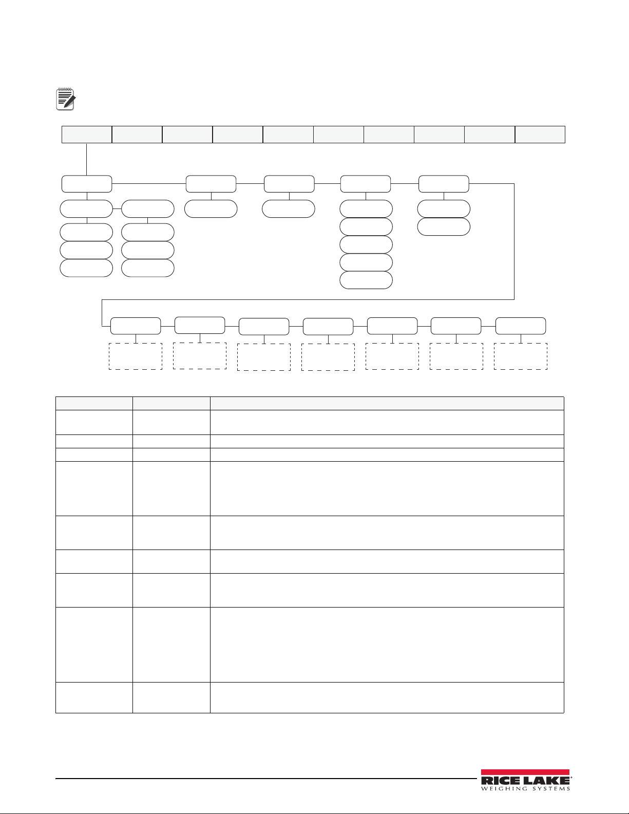
3.1 User Menu Setup
Note
SETPNT
PFRMAT
MISC
TARE
0
AUDIT
CALIB
CNT
TIME
DATE
CONFIG
CNT
TIME
DATE
UNITID
000000
TIMDAT
TIME
DATE
ACCUM
TIME
DATE
VIEW
PRINT
CLR Y
MENU CONFIG FORMAT CALIBR PROGRM DIG IN ALGOUT PASWRD USBMEM TEST
VERS
SERIAL
ETHNET USB
See
Figure 3-2
See
Figure 3-3
See
Figure 3-4
See
Figure 3-5
See
Figure 3-6
See
Figure 3-8
See
Figure 3-7
Press the Menu key to access the menu parameters.
The menu key can be pushed while in the weigh mode. The configuration parameters can be accessed by
pressing the setup switch while in the User Menu. See Section 3.2 for configuration setup.
Figure 3-1. Menu Key User Menu
Parameter Choices Description
AUDIT CALIB
CONFIG
TARE 0 View the Tare value.
UNITID 0 – 999999 View and edit the Unit ID (up to a 6 digit number)
ACCUM VIEW
TIME
DATE
PRINT
CLR Y
TIMDAT
TIME
DATE
SETPNT BATCHG
SERIAL COM-1
SETPNT1-8
COM-2
STREAM
ETHNET DHCP
IPADR
NETMSK
USB DEVICE
DFTGWY
MAC
SERVER
CLIENT
TRIGER
View audit trail including the time and date of last configuration or calibration.
Options: CNT, TIME, DATE
View the current accumulator value.
View the time and date of the last accumulation.
Print or clear the accumulator data.
View/set time and date as currently programmed in the indicator.
See Section 1.8.13.
Format date as MMDDYY, DDMMYY, YYMMDD or YYDDMM.
See Section 3.1.1.
Configure serial ports.
See Section 3.1.2.
Configure optional Ethernet ports.
See Section Section 3.1.3.
Configure optional USB port.
See Section 3.1.4.
Table 3-1. Menu Key Parameters
22 480 Legend Series
Page 30
Parameter Choices Description
TIMDAT
ACCUM
SERIALSETPNT
ETHNET
......
BATCHG SETPT1-8
USER
000000
PREACT
SUPVSR
CONFIG FORMAT CALIBR PROGRM DIG IN ALGOUT PASWRD USBMEMMENU TEST
AUTO
OFF
MANUAL
000000
VALUE
OFF
ON
ENABLE
OFF
ON
PUSHAC
OFF
ON
PUSHPR
OFF
ON
WAITSS
HIGHER
LOWER
TRIPKIND
OFF
GROSS
NET
-GROSS
-NET
DELAY
OFF
ON
PUSHTR
000000
HYSTER
OFF
ON
BATSEQ
NONE
1-8
DIGOUT
PFRMAT GFMT
NFMT
ACCFMT
SPFMT
VERS FIRMW
View or configure the print format used for gross, net ticket, accumulator and setpoint
print tickets. See Section 7.0 on page 57 for more information.
See Section 3.1.5.
Displays the firmware and legally relevant firmware currently installed.
LR
MISC POWER
Set miscellaneous parameters, see Section 3.1.7.
BKLGHT
BAT
Table 3-1. Menu Key Parameters (Continued)
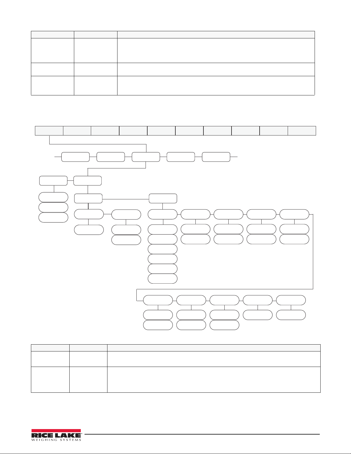
3.1.1 Setpoint Menu
For more information on setpoints, see Section 8.0 on page 59.
Parameter Choices Description
SETPT1-8 USER
BATCHG OFF
SUPVSR
AUTO
MANUAL
Figure 3-2. Setpoint Setup Menu
Setpoint options that do not require a user password, see sub-menu below.
Setpoint options that require a user password, see sub-menu below.
Set to OFF batching is disabled. Set to AUTO or MANUAL to allow a batch sequence to run.
MANUAL requires a batch start signal (BATSTRT digital input or BATSTART serial command)
before the batch sequence can run. AUTO allows batch sequences to repeat continuously,
after receiving a single batch start signal.
Table 3-2. Setpoint Setup Menu Parameters
User Menu Setup 23
Page 31
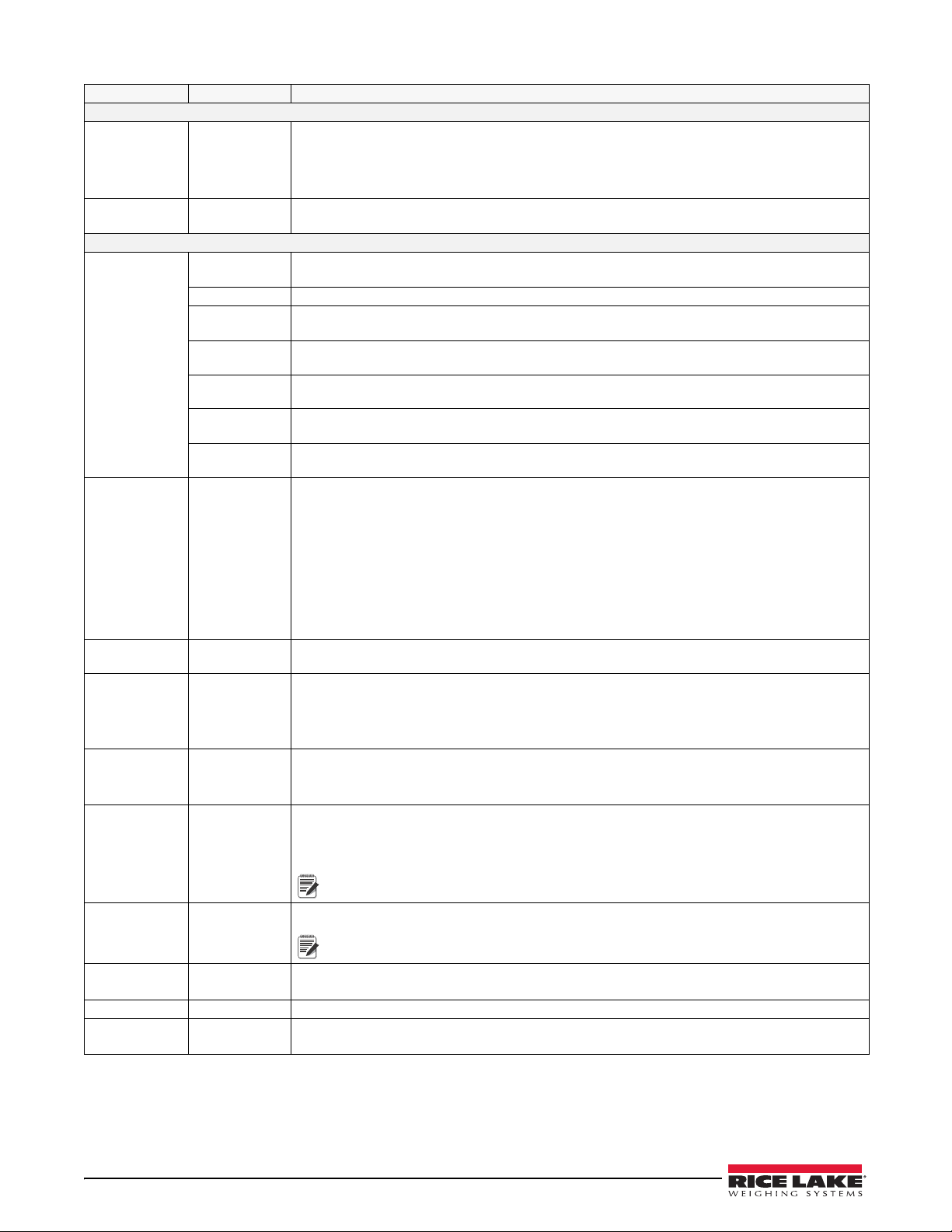
Parameter Choices Description
Note
Note
User submenus
VALUE number Display and edit the setpoint target value.
• For weight-based setpoints: specifies the target weight value, 0 – 999999.
• For time-based setpoints (delay): specifies, in 0.1-second intervals, a time value in the
range 0 – 65535.
ENABLE OFF
Enable or disable the setpoint.
ON
Supervisor Submenus
KIND Specifies the setpoint kind and determines whether function is based on GROSS or NET
weight or based on time value for delay.
OFF Setpoint turned off/ignored.
GROSS Gross setpoint. Performs functions based on the gross weight. The target weight entered is
considered a positive gross weight.
NET Net setpoint. Performs functions based on the net weight. The target weight entered is
considered a positive net weight value.
-GROSS Negative gross weight. Performs functions based on the gross weight. The target weight
entered is considered a negative gross weight.
-NET Negative net weight. Performs functions based on the net weight. The target weight entered is
considered a negative net weight value.
DELAY Delays the batch sequence for a specified time. The length of the delay (in tenths of a second)
is specified by the VALUE parameter.
TRIP HIGHER
LOWER
Trips the setpoint when the weight is higher or lower than the setpoint value.
If batch sequence is off (Continuous Setpoint) with:
• TRIP = HIGHER – the associated digital output will become active when the weight value
is higher than the setpoint value
• TRIP = LOWER – the output is active when the weight is below the setpoint value.
If batch sequence is on (Batching Setpoint) with:
• TRIP = HIGHER – the associated digital output is active until the setpoint value is reached
or exceeded
• TRIP = LOWER – the output is active until the weight goes below the setpoint value.
WAITSS OFF
Wait for Standstill – Value must be stable to satisfy this action.
ON
PUSHPR OFF
ON
Push Print – Specify ON to perform a print operation when the setpoint is satisfied. This action
does not wait for standstill, it prints as soon as the setpoint is satisfied.
To wait for standstill before printing, set the WAITSS parameter to ON.
This action uses the Setpoint Print Format.
PUSHAC OFF
ON
Push Accumulator – Specify ON to update the accumulator when the setpoint is satisfied. This
action does not wait for standstill, it accumulates as soon as the setpoint is satisfied.
To wait for standstill before accumulating, also set the WAITSS parameter to ON.
PUSHTR OFF
ON
Push Tare – Specify ON to perform an acquire tare operation when the setpoint is satisfied.
This action does not wait for standstill, it tares the weight as soon as the setpoint is satisfied.
To wait for standstill before performing the tare, also set the WAITSS parameter to ON.
PUSHTR acquires the tare regardless of the value specified for the REGULAT
parameter on the PROGRAM menu.
DIGOUT NONE
1-8
Digital Output – specify the digital output associated with this setpoint.
To use outputs 1-4 and inputs 1-2, short jumper A1 (JP2)
To use outputs 5-8 and inputs 3-4, short jumpers A0 (JP1) and A1 (JP2)
BATSEQ OFF
ON
Determines if the setpoint is a continuously running setpoint (OFF), or part of a batch sequence
(ON).
PREACT number Allows a setpoint to shut off before the setpoint is satisfied to allow for material in suspension.
HYSTER number Specifies a band around the setpoint value that must be exceeded before the setpoint, once
off, can trip on.
Table 3-2. Setpoint Setup Menu Parameters (Continued)
24 480 Legend Series
Page 32
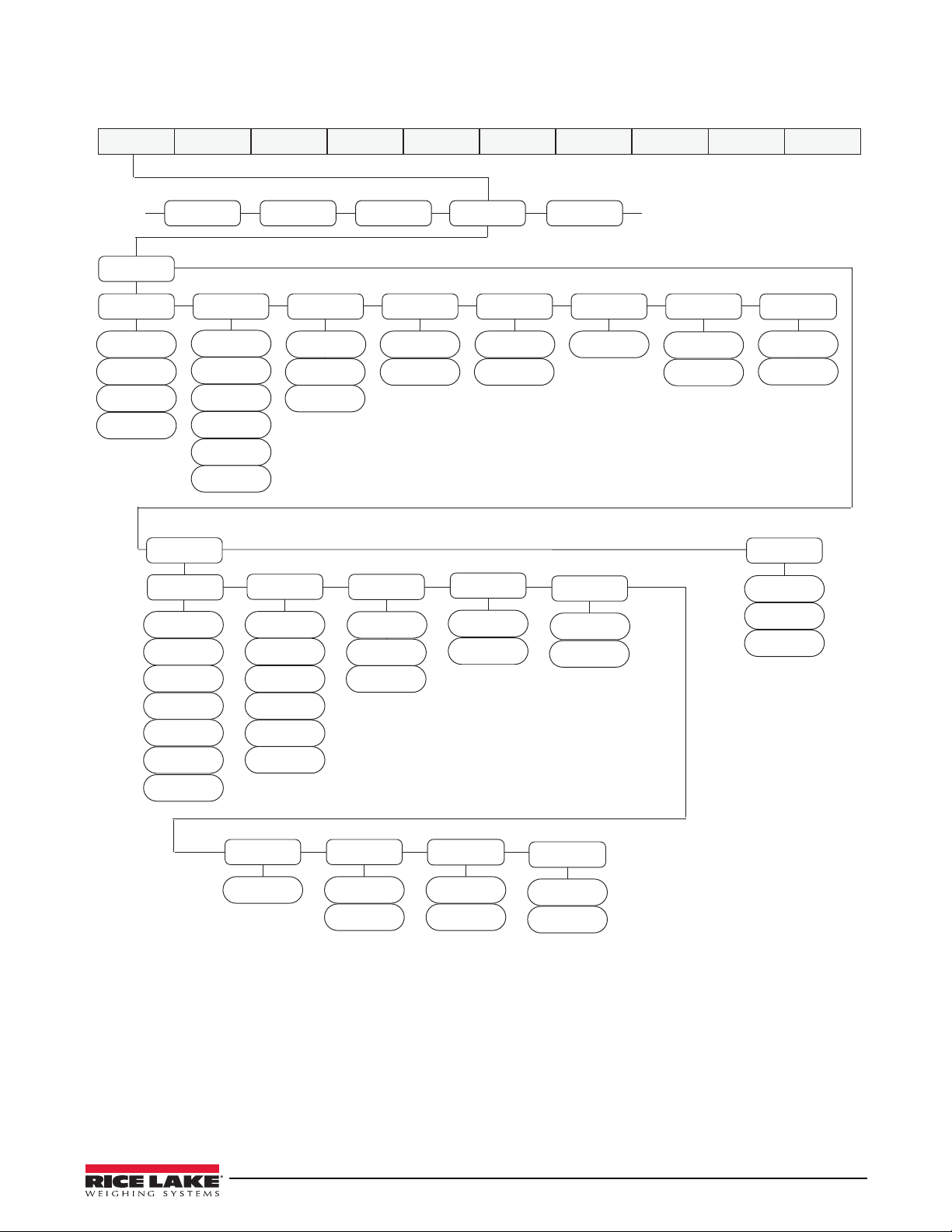
3.1.2 Serial Menu
COM-1
TIMDAT
ACCUM
SERIALSETPNT
PFRMAT
......
COM-2
STREAM
TRIGER
DEMAND
PRN
NONE
COMAND
BAUD
LOCAL
REMOTE
NONE
STRUR
STRLFT
STRIND
ECHO
OFF
ON
SBITS
1 STOP
2 STOP
TERMIN
CR
CR-LF
EOLDLY
000
BITS
7ODD
7EVEN
8NONE
PRNMSG
OFF
ON
BAUD
4800
2400
1200
19200
38400
9600
BITS
7ODD
7EVEN
8NONE
SBITS
1 STOP
2 STOP
TERMIN
CR
CR-LF
EOLDLY
000
ECHO
OFF
ON
PRNMSG
OFF
ON
TRIGER
STR2
STR3
STR4
NONE
PRN
STR1
STR5
4800
2400
1200
19200
38400
9600
MENU CONFIG FORMAT CALIBR PROGRM DIG IN ALGOUT PASWRD USBMEM TEST
See Section 9.3 for information about the 480 serial data format.
Figure 3-3. Serial Menu
User Menu Setup 25
Page 33
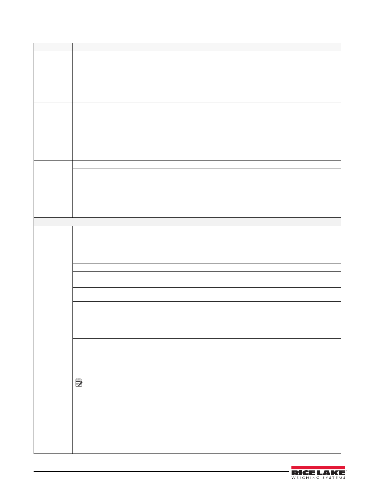
Parameter Choices Description
Note
COM-1 TRIGER
Specifies settings for COM-1.
BAUD
BITS
SBITS
TERMIN
EOLDLY
ECHO
PRNMSG
COM-2 TRIGER
Specifies settings for COM-2.
BAUD
BITS
SBITS
TERMIN
EOLDLY
ECHO
PRNMSG
STRUR
STREAM Specifies the operating mode of the indicator. See Section 9.4 on page 65.
NONE Indicator operates normally, COM-2 will not stream, even if the TRIGER is set to a streaming
parameter (STR1-5)
LOCAL Indicator operates normally, data streaming occurs on COM-2 if the TRIGER is set to stream
data (STR1-5)
REMOTE Indicator acts as a Serial Data scale, displaying values based on a received steam of Serial
Data into COM-2. It also sends keypress commands back through COM-2 to the Local
indicator.
Submenus COM-1 and COM-2
TRIGER
(COM-1)
DEMAND Demand port – printing is performed by pressing the Print key or when a KPRINT EDP
Specifies the ports mechanism for triggering a transmission of data.
command is received. This port will also allow operation and EDP commands.
PRN Printer Port – printing is performed by pressing the Print key. The port does not allow
operation of EDP commands.
NONE Port is inactive.
COMAND Command port – allows operation of EDP commands, but will not print.
TRIGER
(COM-2)
NONE Port is inactive.
PRN Printer Port – Printing is performed by pressing the Print key. The port does not allow
operation of EDP commands.
STR1 Port is used to transmit a continuous stream of data according to RLWS stream format.**
STR2 Port is used to transmit a continuous stream of data according to Toledo8142 stream
format.*
STR3 Port is used to transmit a continuous stream of data according to Cardinal738 stream
format.*
STR4 Port is used to transmit a continuous stream of data according to Weightronix WI-120
stream format.*
STR5 Port is used to transmit a continuous stream of data according to consolidated stream
format.*
*STREAM must be set to local to enable streaming.
See Section 9.3 on page 62 for more information on Stream formats.
Com-2 streams simultaneously on both the RS-232 and 20mA outputs.
BAUD 9600
Baud rate. Selects the transmission speed of data.
19200
38400
1200
2400
4800
BITS 8NONE
Selects number of data bits and parity of data.
7EVEN
7ODD
Table 3-3. Serial Menu Parameters
26 480 Legend Series
Page 34
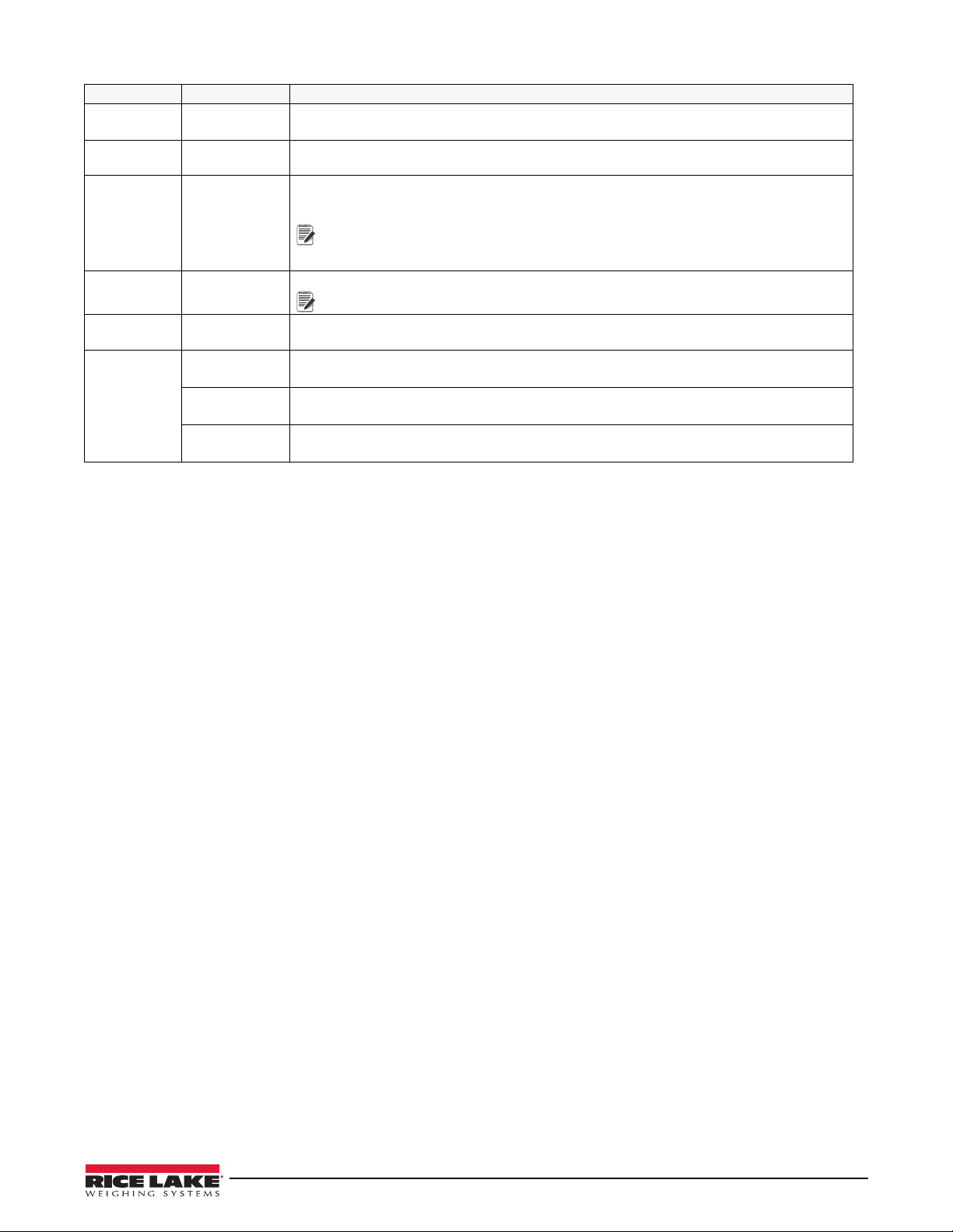
Parameter Choices Description
Note
Note
SBITS 1 STOP
Stop bits – Sets the number of stop bits to 1 or 2.
2 STOP
TERMIN CR/LF
Termination character – selects line termination character(s) for data sent.
CR
EOLDLY 000000
0 – 255
End-of-line delay – specifies, in 0.1 second intervals, the delay between transmitted lines of
data.
An end-of-line delay may be required for continuous transmission at slower
baud rates to ensure the receiving buffer is empty before another string is
transmitted.
ECHO ON
OFF
PRNMSG OFF
Specifies whether characters received by the port are echoed back to the sending unit.
Port 1 default is ON, Port 2 default is OFF
Print displays when a demand print is performed.
ON
STRUR Com 2 only – defines the stream data update rate when one of the stream formats is
selected.
STRLFT Stream Legal for Trade – the weight information in the data stream is updated at the same
rate as the indicator's display.
STRIND Stream industrial – the weight information in the data stream is updated at up to the A/D
sample rate.
Table 3-3. Serial Menu Parameters (Continued)
User Menu Setup 27
Page 35
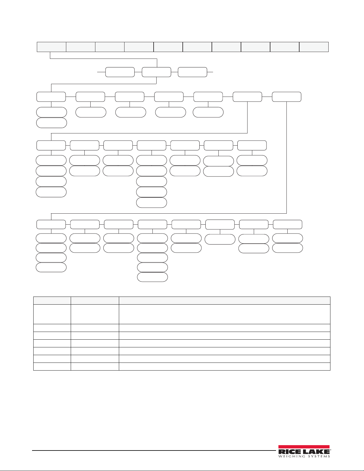
3.1.3 Ethernet Menu
0 - 65535
0 STR - 1
STR - 2
STR - 5
STR - 4
STR - 3
SERIAL
ETHNET
USB
...
...
IPADRS NETMSK DFTGWY MAC SERVER CLIENT
0.0.0.0
ON
OFF
0.0.0.0 0.0.0.0
00.00.00.00.00.00
DHCP
STRIND
STRLFT
COMAND
DEMAND
TRIGER TIMOUT
TERMIN SFMT
PORT EOLDLY ECHO
CR
CR/LF
0
0 - 255
1 - 65535
10001
ON
OFF
0 - 65535
0 STR - 1
STR - 2
STR - 5
STR - 4
STR - 3
STRIND
STRLFT
COMAND
DEMAND
TRIGER
TERMIN
CR
CR/LF
EOLDLY
0
0 - 255
RMPORT
1 - 65535
1
ECHO
ON
OFF
TIMOUT SFMT
RMOTIP
0.0.0.0
MENU CONFIG FORMAT CALIBR PROGRM DIG IN ALGOUT PASWRD USBMEM TEST
Parameter Choices Description
DHCP ON
OFF
Dynamic Host Configuration Protocol (DHCP)
ON – Dynamic allocation of IP address
Figure 3-4. Ethernet Menu Layout
OFF – Static allocation of IP address
IPADRR 0.0.0.0 IP address – a four field value, the range of each field is 0-255
NETMSK 0.0.0.0 SUBNET mask – a four field value, the range of each field is 0-255
DFTGWY 0.0.0.0 Default gateway – a four field value, the range of each field is 0-255
MAC 00.00.00.00.00.00 View the MAC address in hexadecimal base (read only)
SERVER See Submenu below.
CLIENT See Submenu below.
Table 3-4. Ethernet Menu Parameters
28 480 Legend Series
Page 36
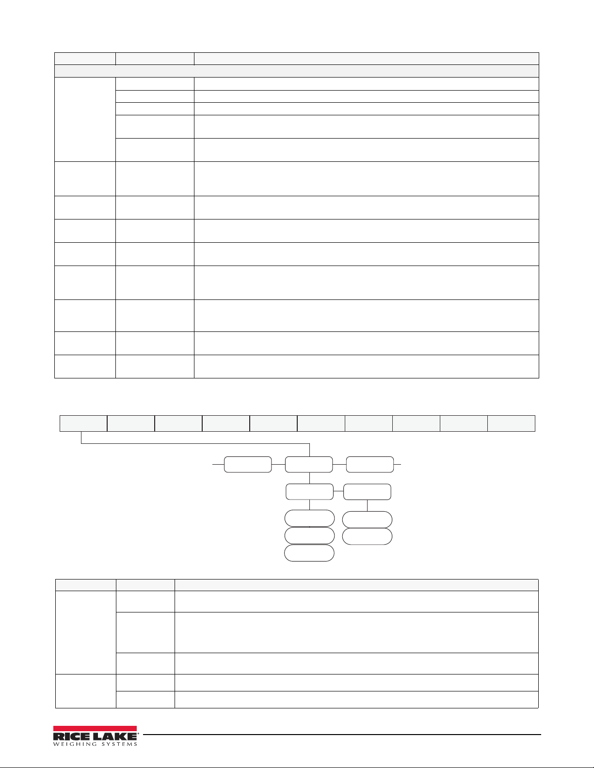
Parameter Choices Description
ETHNET USB
PFRMAT
...
...
TRIGER
DEVICE
PRINTR
HOSTPC
DRIVE
DEMAND
COMAND
MENU CONFIG FORMAT CALIBR PROGRM DIG IN ALGOUT PASWRD USBMEM TEST
SERVER/CLIENT Submenu
TRIGER Selects the operation of the port.
DEMAND Allows operation of EDP commands and will print.
COMAND Allows operation of EDP commands only, does not print.
STRLFT Stream legal for trade scale data – data is transmitted at the configured display update
rate. Will also accept EDP commands and print.
STRIND Stream industrial scale data – data is transmitted up to the configured A/D sample rate.
Will also accept EDP commands and print.
TIMOUT 0
0-65535
TERMIN CR/LF
CR
SFMT STR1-5 Stream format – specifies the stream format used for streaming output of scale data
PORT 10001
1-65535
RMOTIP 0.0.0.0 Remote Host IP address – IP address of the Remote Host (Server) the 480 Client will
RMPORT 1
1-65535
EOLDLY 0
0-255
ECHO OFF
ON
Timeout – inactivity disconnect timeout. A connection (either client or server) is closed if
there is no activity before the timeout expires. Time is in seconds. A timeout value of 0
disables the inactivity disconnect.
Termination. Selects the termination character(s) for data sent from the port.
(TRIGER=STRLFT or STRIND). See Section 9.3 on page 62.
The TCP port number of the 480 server.
Server level only.
connect to.
Client level only.
Remote Host TCP Port number – The TCP Port of the Remote Host (Server) the 480 Client
will connect to
Client level only.
Port end-of-line delay – specifies (in 0.1 second intervals) the delay between transmitted
lines of data.
Specifies whether characters received by the port are echoed back to the sending unit.
Table 3-4. Ethernet Menu Parameters (Continued)
3.1.4 USB Menu
Figure 3-5. USB Menu Layout
Parameter Choices Description
DEVICE HOSTPC The port is assigned to a HOSTPC, the protocol is a demand type similar to serial
communications demand mode, meaning that the port supports EDP commands and Printing.
DRIVE The port is assigned to a flash drive, the data is written in a FAT32 system, no special driver is
PRINTR When set to PRINTR mode, the USB port can be connected to a USB printer using an
TRIGER COMAND Allows operation of EDP commands only. Does not print.
required.
Use the USBMEM Load and Save functions, found in the Configuration Menu (Section 3.2.1 on
page 33), to load configuration data to or from a flash drive.
appropriate USB cable. See Section 9.8 on page 66.
DEMAND Allows operation of EDP commands and prints.
Table 3-5. USB Menu
User Menu Setup 29
Page 37
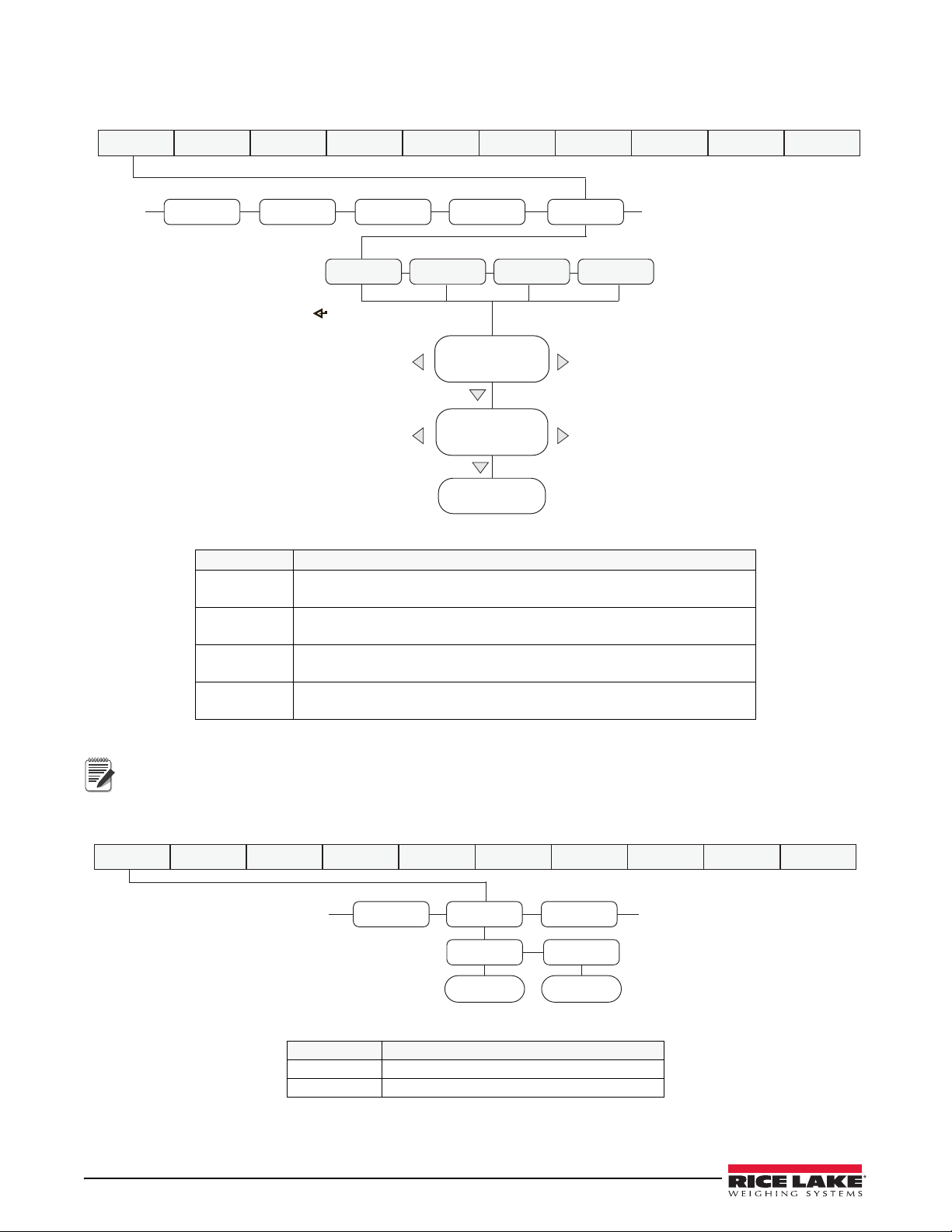
3.1.5 Print Format Menu
TIMDAT
ACCUM
SERIALSETPNT
PFRMAT
......
Display first 6
characters of format
Display and edit
active character and
ASCII value
Delete active
character
Scroll right in format string
Scroll left in format string
Increment ASCII value of active character
Decrement ASCII value of active character
Press to insert a space
before the active character
GFMT
NFMT
ACCFMT
SPFMT
MENU CONFIG FORMAT CALIBR PROGRM DIG IN ALGOUT PASWRD USBMEM TEST
Note
VERSPFRMAT
MISC
......
FIRMW
LR
Legally
Relevant
VERSION VERSION
MENU CONFIG FORMAT CALIBR PROGRM DIG IN ALGOUT PASWRD USBMEM TEST
See Section 7.0 for information about custom print formatting.
Figure 3-6. Print Format Menu
Parameter Description
GFMT Gross demand print format string
Default – GROSS<G><NL2><TD><NL>
NFMT Net demand print format string
Default – GROSS<G><NL>TARE<SP><T><NL>NET<SP2><N><NL2><TD><NL>
ACCFMT Accumulator demand print format string
Default – ACCUM <A><NL><DA><SP><TI><NL>
SPFMT Setpoint print format
Default – <SCV><SP><SPM><NL>
Table 3-6. Print Format Parameters
Format strings are case sensitive and must be entered in upper case.
3.1.6 Version Menu
The VERS menu is used to view the firmware version.
FIRMW Displays Firmware Version
LR Displays legally relevant firmware version
Figure 3-7. Firmware Version User Menu
Parameter Description
Table 3-7. Firmware Version Menu Parameters
30 480 Legend Series
Page 38
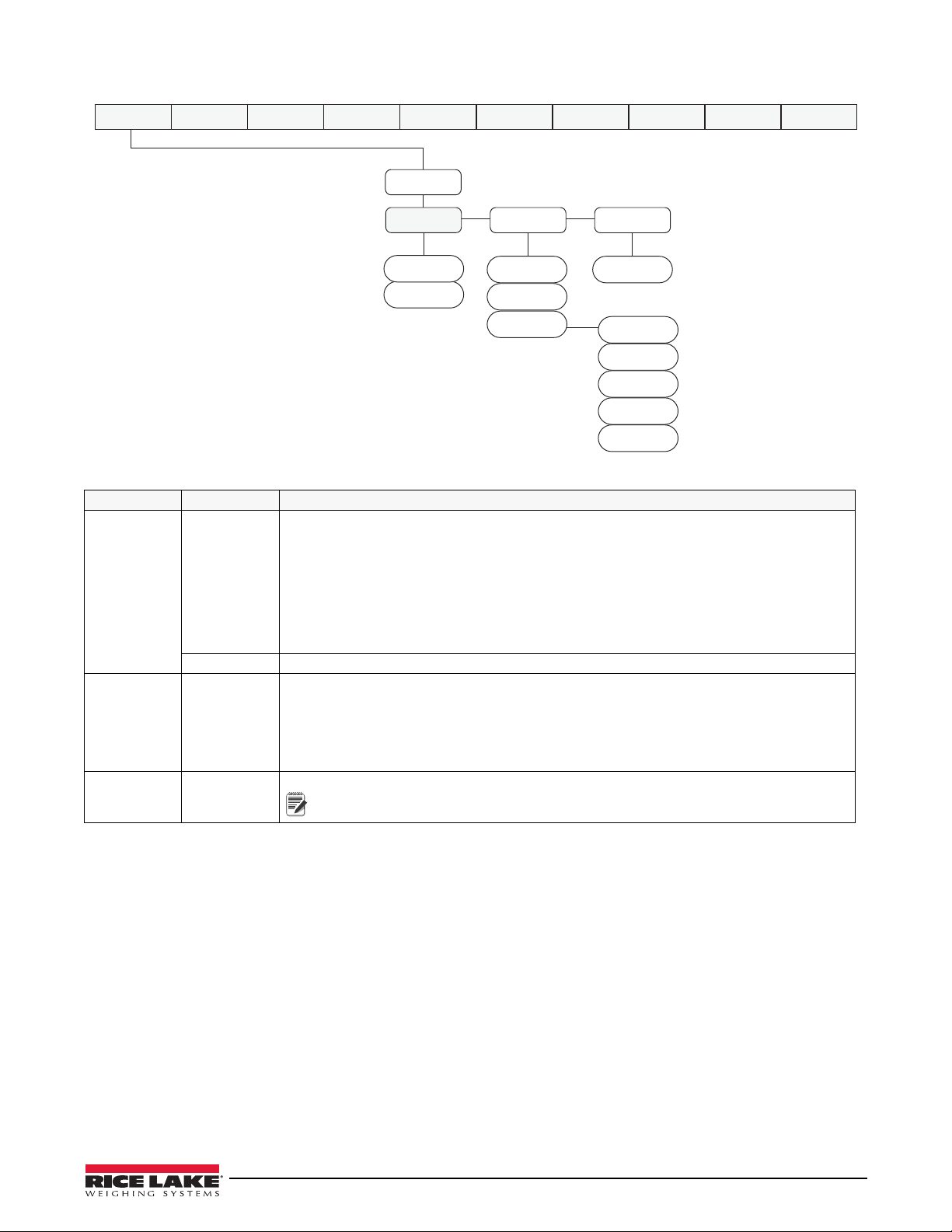
3.1.7 MISC Menu
MISC
POWER
BKLGHT BAT
OFF
ON
AUTO
10 SEC
30 SEC
1 MIN
5 MIN
10 MIN
BAT LEVEL
AUTO
MANUAL
MENU CONFIG FORMAT CALIBR PROGRM DIG IN ALGOUT PASWRD USBMEM TEST
Note
Figure 3-8. Misc. Menu
Parameter Choices Description
POWER AUTO The power up functionality depends on whether the battery option is installed:
• If the battery option is not installed, the indicator turns on automatically when connected
to AC power. It turns off by disconnecting the AC power or by pressing the power key.
• If the battery option is installed, and CPU Jumper 4 is connected, the indicator turns on
automatically when connected to AC power. It turns off by disconnecting the AC power or
by pressing the power key. This configuration is not recommended due to increased
leakage current from the battery when the indicator is turned off.
• If the battery option is installed, and CPU Jumper 4 is disconnected, the indicator only
turns on and off by pressing the power key.
MANUAL Indicator powers On/Off by pressing Power key.
BKLGHT OFF
ON
AUTO
BAT LEVEL Allows reading the battery level in mV units.
Allows control of the LCD backlight.
OFF – backlight always off.
ON – backlight always on.
AUTO - backlight will turn off after the configured amount of time, if no buttons are pressed
and there is no change in the weight. Once either of these occurs, the backlight will turn on.
Auto time Options: 10 sec, 30 sec, 1 min, 5 min,10 min.
If there is not a battery option installed, NOBATT will display.
When the battery is charging, CHRNG will display.
Table 3-8. MISC Menu Parameters
User Menu Setup 31
Page 39
3.2 Configuration Using the Front Panel (Legal for Trade)
Note
The 480 indicator can be configured using a series of menus accessed through the indicator front panel when the
indicator is in configuration mode.
When the indicator is placed in configuration mode,
first of eight main menus used to configure the indicator. Detailed descriptions of these menus are given in
Section 3.2.1 on page 33. When configuration is complete, return to
configuration mode and save changes. Then replace the configuration switch access screw.
T o place the indicator into the configuration mode, a configuration switch is accessed by removing the setup switch
access head screw on the enclosure back, see Figure 2-1 on page 10. The switch is activated by inserting a
non-conductive tool into the access hole after pressing the menu switch.
1. Remove setup switch access screw from back of indicator.
2. Using a non-conductive tool, press the button located in the access hole. This allows access to configuration
menus.
CONFIG is shown on the display. The CONFIG menu is the
CONFIG and press the (Zero) key to exit
Menu
CONFIG Configuration Config Graduations (scale capacity), Configure zero tracking, zero range, motion band,
FORMAT Format Config Set primary and secondary units.
CALIBR Calibration Config Calibrate the indicator. See Section 4.0 on page 46 for calibration procedures.
PROGRM Program Config Set power-up and regulatory modes, consecutive numbering and sleep
DIG IN Digital Input User Assign digital input functions. Used only if the Relay option is installed.
ALGOUT Analog Output Config Configure the analog output module. Used only if analog output option is
PASWRD Password Config Enable and edit configuration and user passwords.
USBMEM USB Memory Config Allows the saving and loading of configuration settings from a USB flash
TEST Test Config Used to test A/D, test and set Digital I/O, reset the indicator to default settings
MENU Menu User Non Legal for Trade settings, such as Audit Trail, view Tare, set Unit ID, view/
* Password required for all menus if a password for that level has been entered. See Section 3.2.8.
Required
Password*
Menu Function
overload, tare function, sample rate and digital filtering parameters.
parameters.
installed.
memory device.
and set over and under weighment characteristics.
print Accumulator, set Time/Date, and Non Legal for Trade setting for
Communication Port, Setpoints and Print Format parameters. See Section 3.1.
Can be accessed without pressing the Setup Switch, by pressing
the Menu key on the front panel.
Table 3-9. 480 Menu Summary
32 480 Legend Series
Page 40
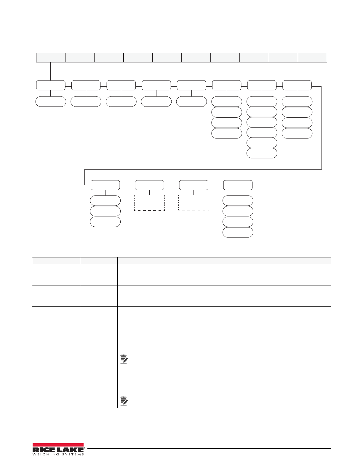
3.2.1 Configuration Menu Structures and Parameter Descriptions
GRADS
ZTRKBN ZRANGE
INIZR
MOTBAN OVRLOA
DSPRAT
SMPRAT
CONFIG FORMAT CALIBR PROGRM DIG IN ALGOUT PASWRD USBMEM MENUTEST
ROLFIL
5 HZ
10 HZ
20 HZ
40 HZ
010000 0 dd 2 % 0 % 0.1 d
FS-2%
FS-1D
FS-9D
FS
0.10 SEC
0.25 SEC
0.50 SEC
0.75 SEC
1.00 SEC
NONE
DIGFIL
ADPFIL
OFF
ROLFIL
BOTH
NOTARE
PBTARE
KEYED
TAREFNADPFIL
See
Figure 3-10
See
Figure 3-10
Note
Note
Figure 3-9. Configuration Menu
Parameter Choices
GRADS 10000
1 – 100000
ZTRKBN
0 dd
0.0 – 3.0dd
Graduations – specifies the number of full scale graduations. The value entered must be in
the range 1-100 000 and should be consistent with legal requirements and environmental
limits on system resolution.
Zero track band – automatically zeros the scale when within the range specified, as long as
the input is within the configured zero range (ZRANGE parameter). Selections are ± display
divisions. Maximum legal value varies depending on local regulations.
ZRANGE
2%
1% – 100%
INIZR 0 %
0 – 100%
MOTBAN 0.1d
0.0d – 100d
Zero range – selects the range within which the scale can be zeroed. The 2% selection is ±
2% around the calibrated zero point, for a total range of 4%. Indicator must be at standstill
to zero the scale.
Initial Zero Range at power up – see Error messages HINOFF and LINOFF in Section 9.1.1
If on power up the weight value is between the ±% range specified of Calibrated Zero, the
indicator will zero off that weight. If outside that range, the indicator will display HINOFF or
LINOFF, depending on whether the initial reading is above or below the range.
If not set at zero, hopper/scale MUST be empty when powered up.
Motion band – sets the level, in display divisions, at which scale motion is detected. If
motion is not detected, the standstill symbol lights.
Some operations, including print, tare and zero, require the scale to be at standstill.
Maximum legal value varies depending on local regulations.
Setting the MOTBAN setting to 0.0 disables motion sensing, the scale will
always be considered stable.
Table 3-10. Configuration Menu Parameters
Description
Configuration Using the Front Panel (Legal for Trade) 33
Page 41
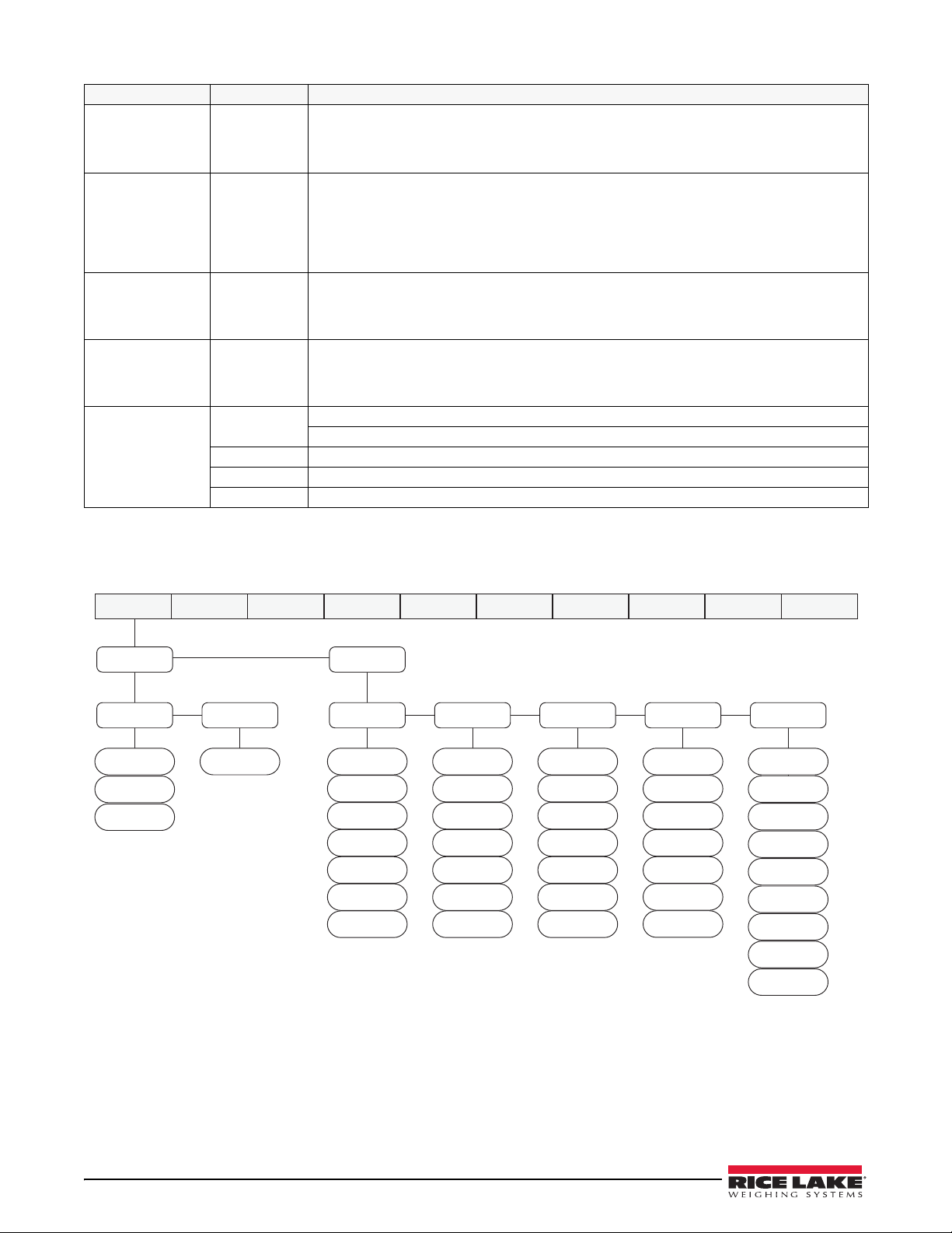
Parameter Choices
CONFIG FORMAT CALIBR PROGRM DIG IN ALGOUT PASWRD USBMEM MENUTEST
ADPFIL
AFTHRH
000002
AFSENS
LIGHT
MEDIUM
HEAVY
2
4
8
16
32
64
1
RFSTG3
2
4
8
16
32
64
1
RFSTG2
2OUT
4OUT
8OUT
16OUT
32OUT
64OUT
128OUT
RFSENS
NONE
2 dd
100 dd
50 dd
20 dd
10 dd
5 dd
200 dd
250 dd
RFTHRHRFSTG1
2
4
8
16
32
64
1
ROLFIL
OVRLOA FS+2%
FS+1D
FS+9D
FS
DSPRAT 0.1SEC
0.25 SEC
0.5 SEC
0.75 SEC
1 SEC
NONE
SMPRAT 5HZ
10HZ
20HZ
40HZ
DIGFIL ADPFIL
ROLFIL
OFF
TAREFN
BOTH
NOTARE No tare allowed (gross mode only)
PBTARE Push-button tare enabled
KEYED Keyed tare enabled
Description
Overload – determines the point at which the display blanks and an out-of-range error
message is displayed. Maximum legal value varies depending on local regulations.
Display rate – sets the update rate for displayed values. Values are in seconds (SEC).
No display filtering – the display is updated at up to the A/D sample rate.
A/D Sample rate – selects measurement rate, in samples per second, of the
analog-to-digital converter. Lower sample rate values provide greater signal noise immunity.
Adaptive Filter – selects the adaptive digital filter. See Figure 3-10.
Rolling Average Filter - selects the rolling average filter. See Figure 3-10.
OFF- Disables the digital filter.
See Section 9.11 on page 68 for more information on Digital Filtering.
Tare function – enables or disables push-button and keyed tares.
Both push-button and keyed tares are enabled
Table 3-10. Configuration Menu Parameters (Continued)
3.2.2 Adaptive Filter and Rolling Filter Sub-menu Parameters
Figure 3-10. Adaptive Filter and Rolling Averaging Filter Sub-menu
34 480 Legend Series
Page 42
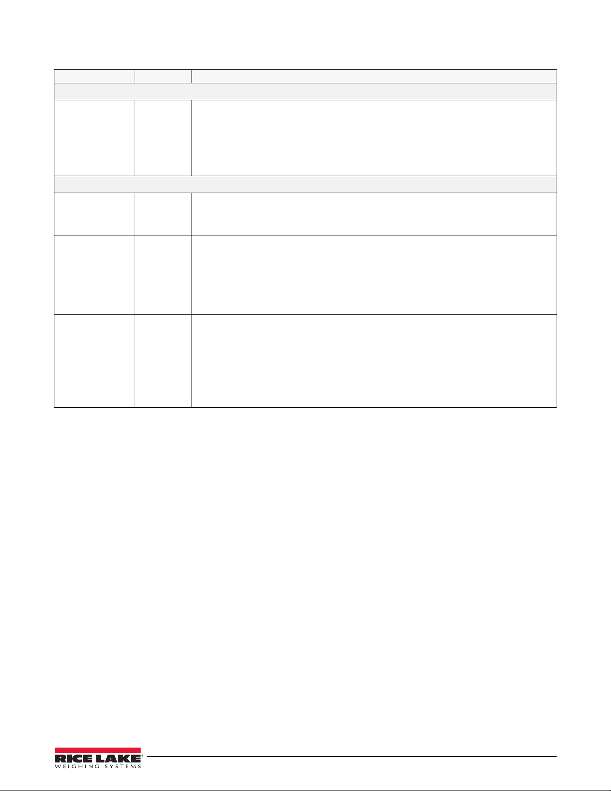
Parameter Choices
Description
ADPFIL Sub-menu
AFSENS LIGHT
MEDIUM
HEAVY
Digital filter cutout sensitivity – the light setting responds quickly to small weight changes and
is less stable. The heavy setting responds slowly to small weight changes and is more stable.
Use the heavy setting in an unstable environment.
AFTHRH 000002 Digital filter cutout threshold – specifies the filter threshold, in weight value. When a weight
change exceeds the value set for threshold, digital filtering is suspended. A setting of zero
disables the filter. The decimal point in the entered value is assumed, so if the display division
is 1lb, a value of 1 is equal to 1lb. If the dd is 0.1lb, a value of 1 is equal to 0.1lb.
ROLFIL Sub-menu
RFSTG1
RFSTG2
RFSTG3
2, 4, 8, 16,
32, 64, 1
Rolling filter stages – the number of A/D samples that are averaged in each stage.
A higher number gives a more stable display by minimizing the effect of a few noisy readings,
but slows down the settling rate of the indicator. See Section 9.11 on page 68 for more
information on digital filtering.
RFSENS 8OUT
16OUT
32OUT
Rolling filter cutout sensitivity – specifies the number of consecutive readings that must fall
outside the rolling filter threshold (RFTHRH parameter) before digital filtering is suspended. If
NONE is selected, the filter is always enabled.
64OUT
128OUT
2OUT
4OUT
RFTHRH NONE
2 dd
5 dd
Rolling filter cutout threshold – specifies the rolling filter threshold, in display divisions. When a
specified number of consecutive scale readings (RFSENS parameter) fall outside of this
threshold, digital filtering is suspended. If NONE is selected, the filter is always enabled.
10 dd
20 dd
50 dd
100 dd
200 dd
250 dd
Table 3-11. Adaptive Filter and Rolling Filter Submenu Parameters
Configuration Using the Front Panel (Legal for Trade) 35
Page 43
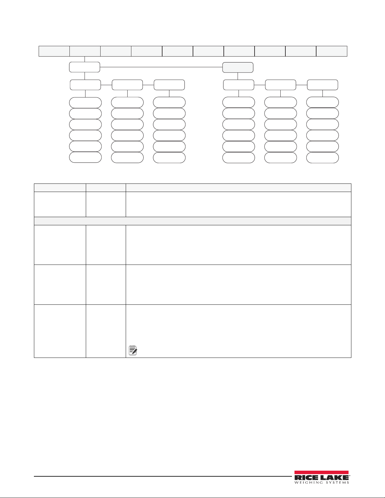
3.2.3 Format Menu
PRIMAR
SECNDR
CONFIG FORMAT CALIBR PROGRM DIG IN ALGOUT PASWRD USBMEM MENUTEST
DECPNT
888888
88.8888
888.888
8888.88
88888.8
8.88888
DSPDIV
1d
2d
5d
10d
20d
50d
UNITS
T
G
LB
KG
OZ
TN
DECPNT
888888
88.8888
888.888
8888.88
88888.8
8.88888
DSPDIV
1d
2d
5d
10d
20d
50d
UNITS
T
G
LB
KG
OZ
TN
Note
Figure 3-11. Format Menu
Parameter Choices Description
PRIMAR
SECNDR
Sub-menus
DECPNT 888888
DSPDIV 1
UNITS lb
DECPNT
DSPDIV
UNITS
8.88888
88.8888
888.888
8888.88
88888.8
2
5
10
20
50
kg
OZ
TN
T
G
Primary Units – specifies the capacity, decimal position, display divisions, and units used.
Secondary Units – specifies the capacity, decimal position, display divisions, units and
conversion multiplier used. See below for submenu parameter descriptions.
Decimal point location – specifies the location of the decimal point in the primary unit
display. Value should be consistent with local legal requirements.
Primary default – 888888
Secondary default – 88888.8
Enter divisions (external) in primary units, the scale resolution will be determined by the
formula CAP/DIV = Resolution.
Primary default – 1
Secondary default – 5
Specifies primary units for displayed and printed weight. Values are: lb = pound;
kg = kilogram; OZ = ounce; TN = short ton; T = metric ton; G = gram
Primary default – lb
Secondary default – kg
Indicators sold outside North America are configured with kg for both
primary and secondary units.
Table 3-12. Format Menu Parameters
36 480 Legend Series
Page 44
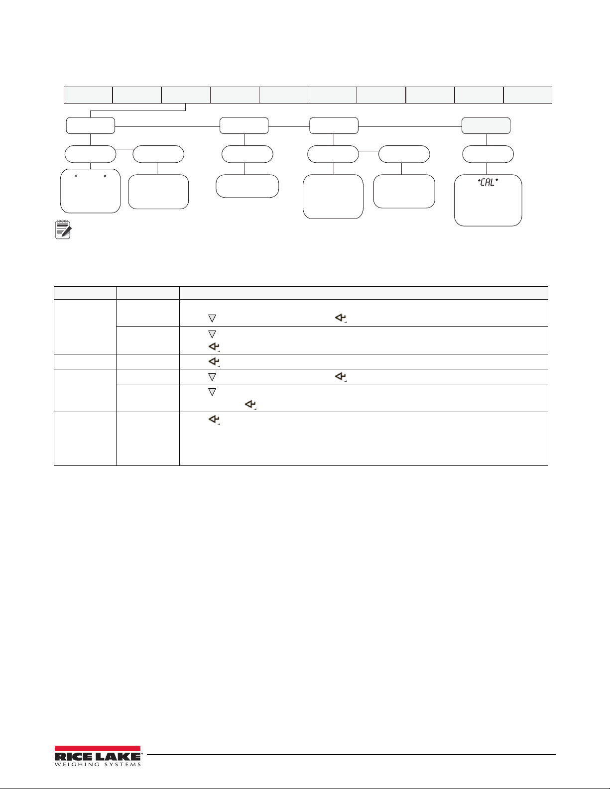
3.2.4 Calibration Menu
WZERO
WVAL
WSPAN
REZERO
Display and edit
zero calibration
mV value
Display and edit
span calibration
mV value
Press Enter to
remove offset from
zero and span
calibrations
Display and edit
test weight value
ENTER
Press Enter to
capture the span
net mV value
CONFIG FORMAT CALIBR PROGRM DIG IN ALGOUT PASWRD USBMEM MENUTEST
ZERO
EDIT
CAL
000000
EDIT
CAL
Press Enter to
capture the
zero mV value
ENTER
EDIT is the current calibrated value that can be edited.
Note
See Section 4.0 on page 46 for Calibration p r ocedures.
Figure 3-12. Calibration Menu
Parameter Choices Description
WZERO
CAL
EDIT
WVAL number
WSPAN CAL
EDIT
REZERO ZERO
(Flashing)
Do not adjust this value after WSPAN has been set.
Press
to display ENTER, then press to capture the zero value.
Press to display the current captured zero mV value. The value may be edited as required.
Press to save the edited value.
Press to display and edit the test weight value.
Press
to display ENTER, then press to capture the net span value.
Press to display the current captured net span mV value. The value may be edited as
required. Press to save the edited value.
Press to remove the weight of the testing apparatus like hooks or chains used during the
calibration process.
Always use this parameter after WZERO and WSPAN have been set to recapture a new zero
value. See Section 4.1 on page 46 for more information about using this parameter.
Table 3-13. Calibrat i on Menu Parameters
Configuration Using the Front Panel (Legal for Trade) 37
Page 45
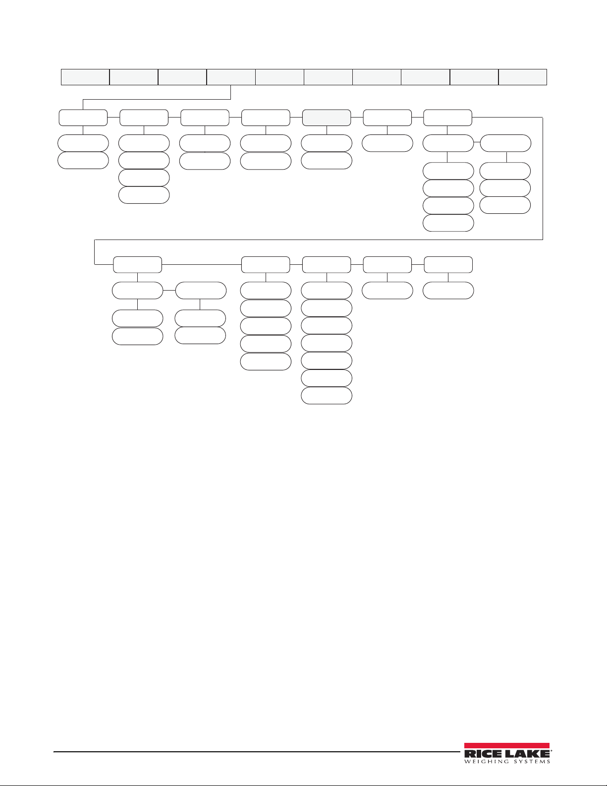
3.2.5 Program Menu
CONFIG FORMAT CALIBR PROGRM DIG IN ALGOUT PASWRD USBMEM MENUTEST
SLEEP
NEVER
2 MIN
5 MIN
10 MIN
1 MIN
STDBY
10 SEC
60 SEC
1 SEC
2 SEC
3 SEC
5 SEC
OFF
WGTHRH
0-FS
DDTHRH
0-999999
RTZGRD
0
ACCUM
OFF
ON
CONSTU
000000
0-999999
CONSNU
000000
0-999999
REGULA
NTEP
OIML
CANADA
NONE
PWRUPM
GO
DELAY
DATE
MMDDYY
DDMMYY
YYDDMM
YYMMDD
DATFMT DATSEP
SLASH
DASH
SEMI
TIMFMT
24 HOUR
12 HOUR
TIME
COLON
COMMA
TIMSEP
Figure 3-13. Program Menu
38 480 Legend Series
Page 46
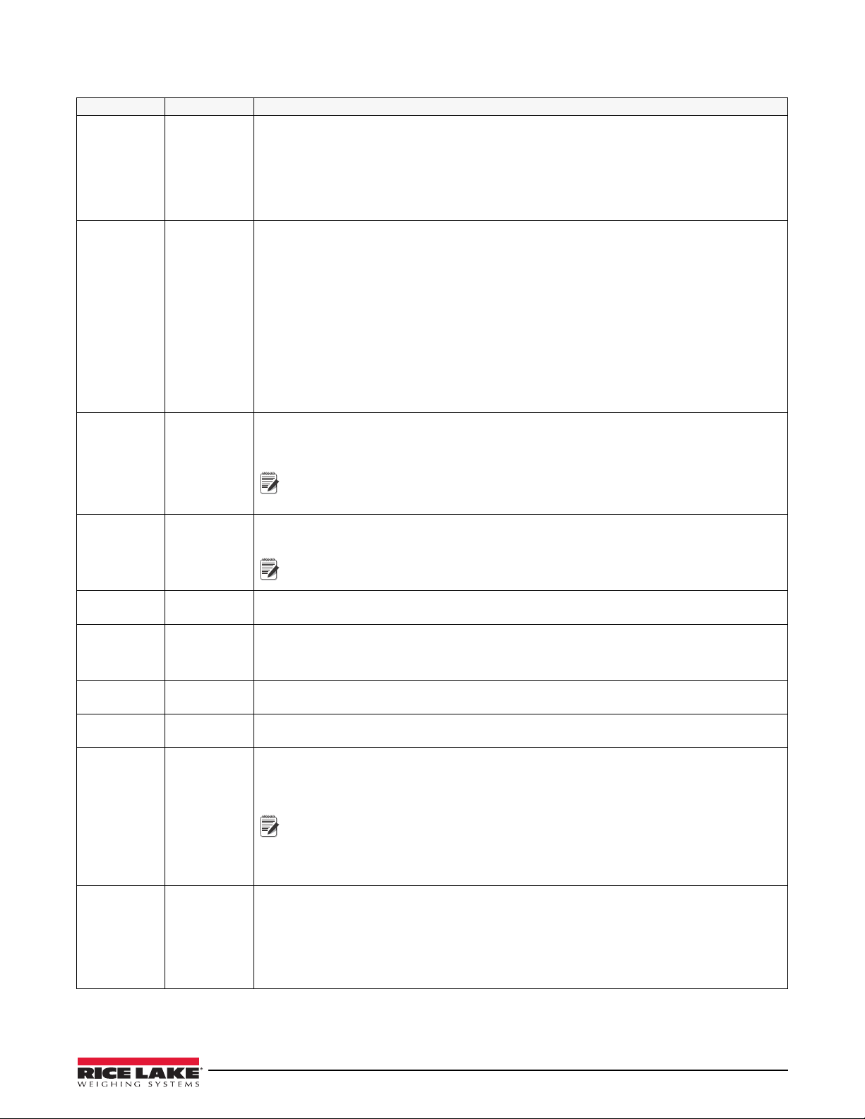
Parameter Choices Description
Note
Note
Note
PWRUPM GO
DELAY
Power up mode – when set to GO, the indicator goes into operation immediately after a brief
power up display test.
When set to DELAY, the indicator performs a power up display test and then enters a 30 second
warm-up period. If no motion is detected during the warm-up period, the indicator becomes
operational when the warm-up period ends; if motion is detected, the delay timer is reset and the
warm-up period repeated.
REGULA NTEP
OIML
CANADA
NONE
Regulatory mode – specifies the regulatory agency having jurisdiction over the scale site.
OIML, NTEP, and CANADA modes allow a tare to be acquired at any weight greater than zero.
NONE allows tares to be acquired at any weight value.
OIML, NTEP, and CANADA modes allow a tare to be cleared only if the gross weight is at no
load. NONE allows tares to be cleared at any weight value.
NTEP and OIML modes allow a new tare to be acquired even if a tare is already present. In
CANADA mode, the previous tare must be cleared before a new tare can be acquired.
NONE, NTEP and CANADA modes allow the scale to be zeroed in either gross or net mode as
long as the current weight is within the specified ZRANGE. In OIML mode, the scale must be in
gross mode before it can be zeroed; pressing the ZERO key in net mode clears the tare.
CONSNU 000000
0 – 999999
Consecutive numbering. Allows sequential numbering for print operations. The consecutive
number value will increment following each print operation when the print format used contains
the <CN>, or consecutive number formatting token. This value is read only.
The initial value of this parameter is set to the start up value specified on the
CONSTU parameter. Changing CONSTU immediately resets the consecutive
number used for printing.
CONSTU 000000
0 – 999999
Consecutive number start up value. Specifies the initial consecutive number (CONSNU) value
used when the indicator is reset or configured.
Consecutive numbering starts with number entered.
Example: If 100 is entered the first ticketed printed will be 100.
ACCUM OFF
ON
RTZGRD 0
0 – 999999
Turns the accumulator on and off. Stores the accumulated weight, time and date of last
accumulation.
Return to zero grads to re-arm the accumulator. Default = 0.
Defines the number of graduations from Zero that the weight has to go below before the
accumulator will be re-armed.
DATE DATFMT
DATSEP
TIME TIMFMT
Allows selection of date format and date separator. See Date sub-menu for parameter
descriptions.
Allows selection of time format and separator. See Time sub-menu for parameter descriptions.
TIMSEP
SLEEP NEVER
1MIN
2MIN
5MIN
10MIN
Sleep mode. When weight is stable, no buttons have been pressed, and the weight is below the
sleep weight threshold (WGTHRH), the indicator will enter the sleep mode in the time defined in
the SLEEP Parameter. A NEVER setting will disable the sleep mode.
See Section 9.6 on page 65.
The SLEEP mode will only operate if the indicator is operating on Internal Battery
Power - disconnected from AC power.
Setting the WGTHRH or DDTHRH parameters to 0 also disables sleep mode.
Tare is removed if the indicator goes into sleep mode.
STDBY 1SEC
5SEC
10SEC
15SEC
30SEC
60SEC
Controls the Standby mode.
When in the sleep mode, at the number of STDBY seconds set, the indicator will wake if:
• there is weight on the scale of more than the WGTHRH value
• the weight has is changed greater than DDTHRH value
• it detects that a button is being pressed
OFF
Table 3-14. Program Menu Parameters
Configuration Using the Front Panel (Legal for Trade) 39
Page 47
Parameter Choices Description
WGTHRH 0 – FS
(in primary
units )
DDTHRH 999999
(in display
divisions )
DATE sub-menus
DATFMT MMDDYY
DDMMYY
YYMMDD
YYDDMM
DATSEP SLASH
DASH
SEMI
TIME sub-menus
TIMFMT 24HOUR
12HOUR
TIMSEP COLON
COMMA
Controls the Weight Threshold of the Sleep Mode.
If the weight is above WGTHRH, the indicator will not go into sleep mode.
If the weight is below WGTHRH, it will go into sleep mode if the weight remains stable and no
buttons are pressed, for the time set in the Sleep mode parameter.
Controls the weight change detection feature of SLEEP mode, once the indicator detects that
the weight level on the scale is changed more than DDTHRH it will wake up.
Specifies the format used to display or print the date.
Specifies the date separator character.
Specifies the format used to display or print the time.
Specifies the time separator character.
Table 3-14. Program Menu Parameters (Continued)
40 480 Legend Series
Page 48
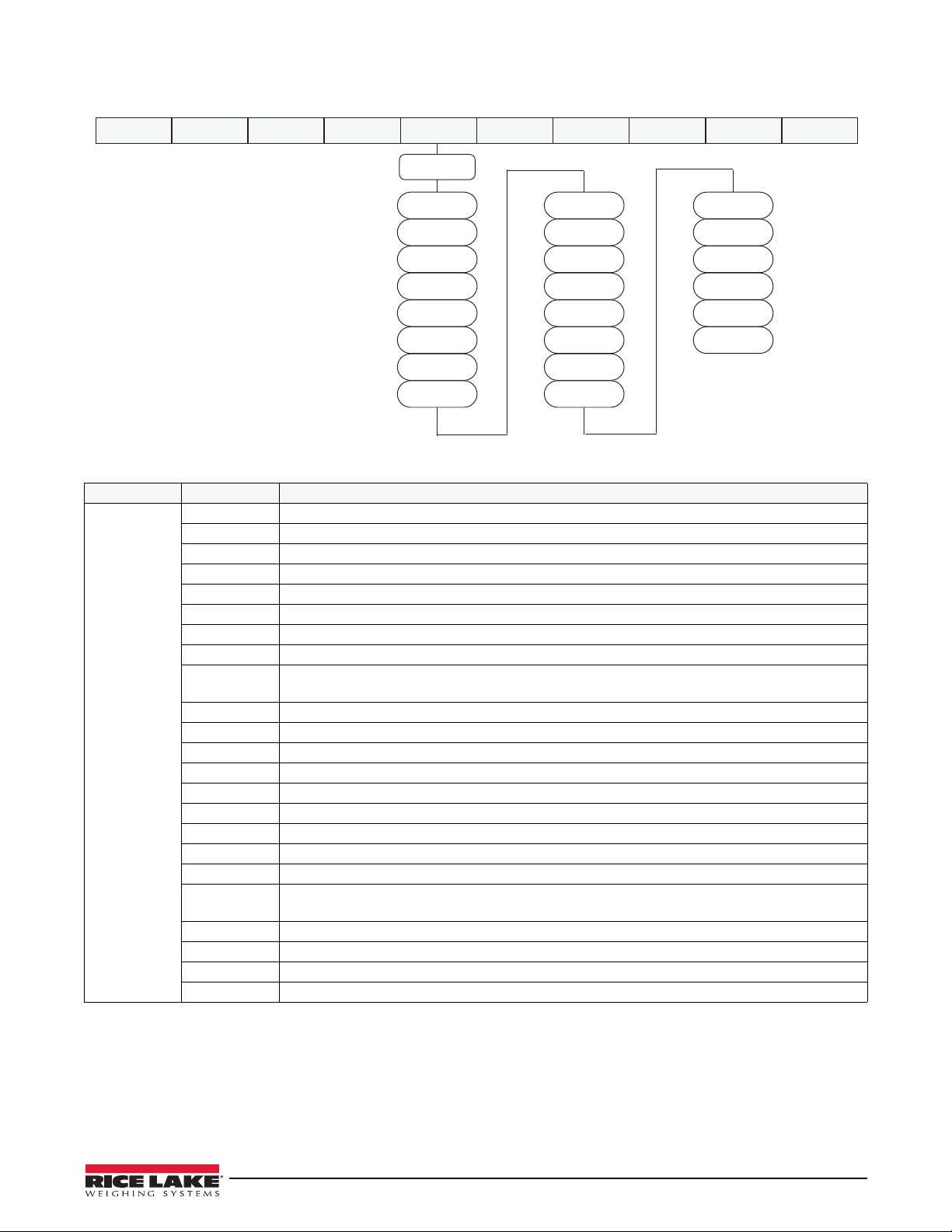
3.2.6 Digital Input Menu
DIGIN1-4
OFF
PRINT
ZERO
TARE
NT-GRS
UNITS
DPSTAR
CLRCN
CONFIG FORMAT CALIBR PROGRM DIG IN ALGOUT PASWRD
USBMEM
MENU
TEST
KBDLOC
BATSTR
BATSTP
BATRES
HOLD
CLRTAR
ACCUM
CLRACC
BATRUN
BATPUS
NET
GROSS
PRI
SEC
Figure 3-14. Digital Input Menu
Parameter Choices Description
DIGIN1
DIGIN2
DIGIN3
DIGIN4
OFF Sets the Digital Input to perform no function.
ZERO Same function as the front panel key.
TARE Same function as the front panel key.
NT-GRS Net-Gross – same function as the front panel key.
UNITS Same function as the front panel key.
DSPTAR Displays the current tare value.
PRINT Same function as the front panel key.
CLRCN Resets the consecutive number to the value specified on the CONSTU parameter (PROGRM
KBDLOC Disables the keypad while the digital input is held active.
HOLD Holds the current display. Releasing this input returns to normal display update mode.
CLRTAR Clears the tare.
ACCUM Displays the accumulator.
CLRACC Clears the accumulator.
BATSTR Starts a batch process.
BATSTP Stops a batch; any restart starts the batch at the beginning.
BATRES Resets the batch process so the pointers are aimed at first batching setpoint.
BATPUS Pauses a batch, but allows it to restart at the point where it was paused.
BATRUN A switch that allows a batch to be started. It must be active to allow any batch to run.
NET Puts the scale in net mode.
GROSS Puts the scale in gross mode.
PRI Puts the scale in primary units.
SEC Puts the scale in secondary units.
Specifies the function activated by digital inputs 1, 2, 3 and 4.
menu).
If not active, and a BATSTRT input is activated, the batch will abort or reset.
Table 3-15. Digital Input Menu Parameters
Configuration Using the Front Panel (Legal for Trade) 41
Page 49
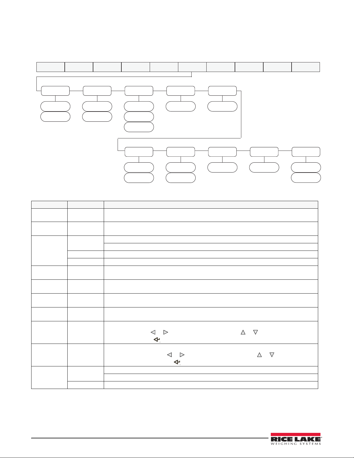
3.2.7 Analog Output Menu
CONFIG FORMAT CALIBR PROGRM DIG IN ALGOUT PASWRD USBMEM MENUTEST
SOURCE
NET
GROSS
MIN
000000
MAX
010000
OFFSET
0%
20%
ERRACT
FULLSC
HOLD
ZEROSC
TWSPAN
000000
TWZERO
000000
MINNEG
NO
YES
MAXNEG
NO
YES
OUTPUT
CURENT
VOLTAG
If the analog output option is installed, configure all other indicator functions and calibrate the indicator (see
Section 4.0 on page 46) before configuring the analo g output. See Section 9.12 on p age 70 for analog output
calibration procedures.
Figure 3-15. Analog Output Menu
Parameter Choices Description
SOURCE GROSS
OFFSET 0
ERRACT
MIN 000000
MAX 010000
MINNEG NO
MAXNEG NO
TWZERO 000000
TWSPAN 000000
OUTPUT
NET
20
FULLSC
HOLD Hold current value.
ZEROSC Set to zero value (0 V or 0 mA) or (2 V or 4 mA)
0 – 999999
0 – 999999
Yes
Yes
0 – 65535
0 – 65535
CURENT
VOLTAG 0-10 V or 2-10 V, depends on OFFSET.
Specifies the weigh data, gross or net, tracked by the analog output.
Zero offset in %. Select 0% for 0–10 V / 0-20 mA; select 20% for 2-10 V / 4-20 mA output.
Set OFFSET after calibrating 0-20 mA.
Error action – specifies how the analog output responds to system error conditions.
Set to full value (10 V or 20 mA).
Specifies the minimum weight value tracked by the analog output. Specify a weight value (in
primary units) in the range 0 – 999999.
Specifies the maximum weight value tracked by the analog output. Specify a weight value (in
primary units) in the range 0 – 999999.
YES implies that the value in MIN is a negative value. NO is the default and implies that MIN is
a positive value.
YES implies that the value in MAX is a negative value. NO is the default and implies that MAX is
a positive value.
Tweak zero – adjust the analog output zero calibration. Use a multimeter to monitor the analog
output value. Press
(flashing) digit. Press to save the new value.
Tweak span – adjust the analog output span calibration. Use a multimeter to monitor the
analog output value. Press
selected (flashing) digit. Press to save the new value.
Defines the output type.
0-20 mA or 4-20 mA, depends on OFFSET.
Table 3-16. Analog Output Menu Parameters
or to select the digit to edit. Press or to edit the selected
or to select the digit to edit. Press or to edit the
42 480 Legend Series
Page 50
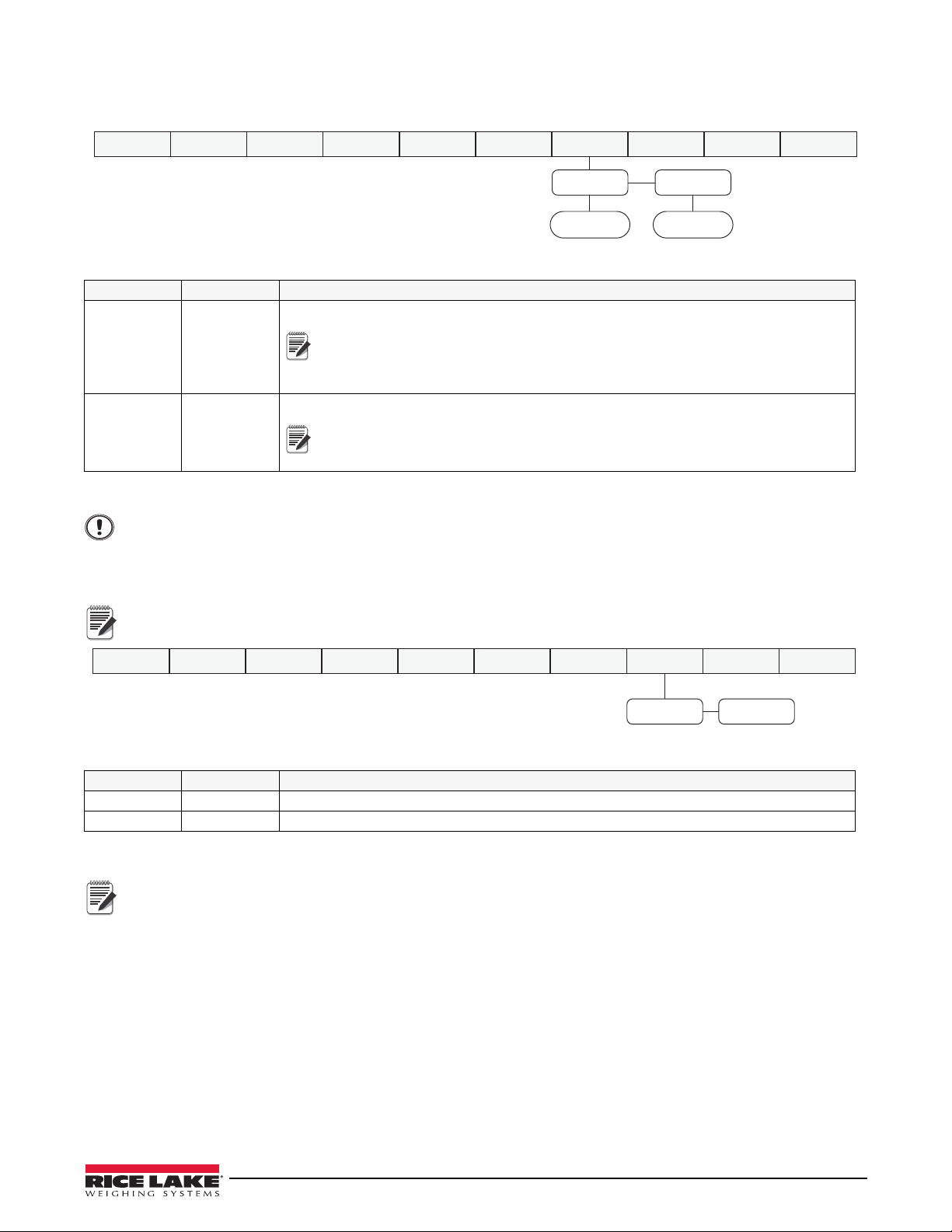
3.2.8 Password Menu
CNFG
USER
CONFIG FORMAT CALIBR PROGRM DIG IN ALGOUT PASWRD USBMEM MENUTEST
000000 000000
Note
Note
Important
SAVE LOAD
CONFIG FORMAT CALIBR PROGRM DIG IN ALGOUT PASWRD USBMEM MENUTEST
Note
Note
The PASSW menu is used to edit or set passwords.
Figure 3-16. Password Menu
Parameter Choices Description
CNFG 0
0 – 999998
USER 0
0 – 999998
Enter 999999 to reset password, this will also reset the configuration back to default values.
Edit configuration password. 0 = no password
If enabled, the configuration password is used for electronic sealing of the
indicator. When configuration password has been entered, the existing
configuration password is required to edit. Entering this menu requires the
SETUP switch to be pressed.
Edit user password. 0 = no password
If enabled, the user password restricts access to the setpoint, serial and print
formatting menus. Once a user password has been entered, the existing user
password is required to edit parameters.
Table 3-17. Password Menu Parameters
3.2.9 USBMEM Menu
USBMEM features will be available in future versions.
Figure 3-17. USBMEM Menu
Parameter Choices Description
SAVE Save the configuration parameters to a file on a flash drive.
LOAD Load the configuration parameters from a file on a flash drive.
Table 3-18. USBMEM Menu Parameters
For more information on using a flash drive to load and save configuration settings, see Section 9.8 on
page 66.
Configuration Using the Front Panel (Legal for Trade) 43
Page 51
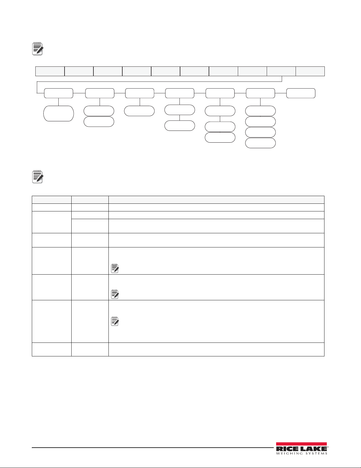
3.2.10 Test Menu
Note
CONFIG FORMAT CALIBR PROGRM DIG IN ALGOUT PASWRD USBMEM MENUTEST
DEFLTALGOUT
0
25%
50%
100%
DIGIN
1-4
VIEW
DIGOUT
1-4
HI
LO
WGMNST
999999
NWGMNT
TOTAL
OVERCAP
ADTEST
Raw A/D
Counts
Note
Note
Note
Note
Access to this menu requires the configuration password if it has been enabled.
Figure 3-18. Test Menu
Digital output relay test.
HI = Active = ON
LO = Inactive = OFF
Parameter Choices Description
ADTEST Displays raw A/D counts.
NWGMNT TOTAL The number of weighments that exceed value set in WGMNST.
OVECAP The number of weighments that exceed the capacity of the scale as set in the config and
format menus. See Table 3-10 and Table 3-12.
WGMNST 0 – 999999 Weighment Threshold – Sets the weight threshold over which WGMNST/Over value will be
counted.
DIGIN 1 – 4
VIEW
Access to display status. Allows selection of each Digital Input to display its current state, HI
or LO.
If the setting cannot viewed, that option is not installed.
DIGOUT 1 – 8
HI
LO
ALGOUT 0
25%
50%
100%
Access to each of the Digital Output and to manually set them individually to HI or LO. HI is
active.
If the setting cannot viewed, that option is not installed.
Allows analog output to be manually set to certain output values for calibration and test of
external equipment
The analog output must not be in an error state as that will override these
settings. When the display division has a decimal, the test outputs will be
offset by the decimal place.
If the setting cannot viewed, that option is not installed.
DEFLT Resets all parameters to factory defaults. At DEFLT, press Gross/Net, indicator will display
SAVING and cycle power.
Table 3-19. Test Menu Parameters
3.2.11 User Menu Setup
See Section 3.1 on page 22.
44 480 Legend Series
Page 52

3.3 Revolution® Configuration
The Revolution configuration utility provides another method for configuring the 480 indicator. Revolution runs on
a computer to set configuration parameters for the indicator. When Revolution configuration is complete,
configuration data is downloaded to the indicator. Revolution supports both uploading and downloading of
indicator configuration data. This capability allows configuration data to be retrieved from one indicator, edited
and then downloaded to another indicator with an identical hardware configuration. See Section 4.3 on page 47 and
Section 5.0 on page 49 for more information about using Revolution.
Revolution® Configuration 45
Page 53

4.0 Calibration
Note
The 480 can be calibrated using the front panel or the Revolution® configuration utility. Each method consists of
the following steps:
• Zero calibration
• Entering the test weight value
• Span calibration
• Optional rezero calibration for test weights using hooks or chains.
The following sections describe the calibration procedure for each of the calibration methods.
4.1 Front Panel Calibration
The CALIBR sub-menu is used to calibrate the 480. See Section 3.2.4 for the calibration menu structure and
parameter descriptions. To calibrate the indicator using the front panel:
1. Remove the setup switch access screw from the back of the enclosure.
2. Insert a non-conductive tool into the access hole and press the configuration switch. Indicator display
changes to show
3. Press until
4. Remove all weight from the scale platform. If the test weights require hooks or chains, place the hooks or
chains on the scale for zero calibration.
5. Press to
6. Press to
7. Press to
8. Press to calibrate zero. The indicator displays
mV value for the zero calibration is displayed.
9. Press to save the zero calibration value and go to
10. Press to
11. Press to
12. Press to show the test weight value.
13. Press to edit value using the procedure shown in Sectio n 1.7 on page 4 to enter the actual value of the test
weights to be used for the span calibration. Press to store the entered
14. Press to
15. Press to
16. Press to
17. Press to
18. Place test weights on the scale and press to calibrate span. The indicator displays *CAL* while calibration
is in progress. When complete, the net millivolt value of the test weight for the span calibration is displayed.
CONFIG (see Figure 2-1).
CALIBR is displayed.
WZERO.
CAL or press to view or edit the existing value.
ENTER.
*CAL* while calibration is in progress. When complete, the
CAL.
WZERO.
WVAL.
WVAL value.
WVAL.
WSPAN.
CAL or press to view or edit the existing value.
ENTER.
Net mV value is equal to the raw mV value at the span minus the mV value captured for zero.
19. Press to save value and go to CAL.
20. Press to WSPAN. If using chains or hooks for your test weights, proceed with step 21.
If no chains or hooks were used, proceed with step 23.
21. Press to REZERO. The REZERO function is used to remove a calibration offset when hooks or chains are
used to hang the test weights.
22. Remove the hooks or chains used during calibration and remove the test weights from the scale. Press .
ZERO will flash. With all weight removed, press to rezero the scale. This function adjusts the zero and
span calibration values. The indicator displays *CAL* while the zero and span calibrations are adjusted.
23. Press to return to the CALIBR menu.
24. Remove all weight from the scale. Press until the display reads CONFIG. Press to exit configuration
mode.
46 480 Legend Series
Page 54
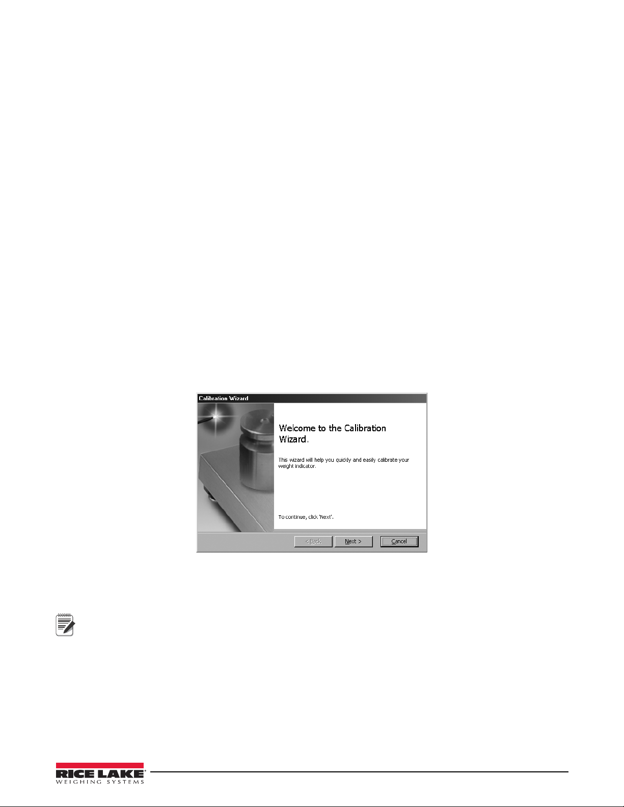
4.2 EDP Command Calibration
Note
To calibrate the indicator using EDP commands, the indicator COM 1 port must be connected to a terminal or
computer. See Section 6.0 on pa ge 51 for more information about using EDP commands.
Once the indicator is connected to the sending device, use the following steps:
1. Place the indicator in configuration mode (display reads
CONFIG) and remove all weight from the scale
platform. If your test weights require hooks or chains, place them on the scale for zero calibration.
2. Send the SC.WZERO EDP command to calibrate zero. The indicator displays
*CAL* while calibration is in
progress.
3. Place test weights on the scale and use the SC.WVAL command to enter the test weight value in the
following format:
WVAL=nnnnnn<CR>
4. Send the SC.WSPAN EDP command to calibrate span. The indicator displays *CAL* while calibration is in
progress.
5. T o remove an offset value, clear all weight from the scale, including items used to hang test weights, and then
send the SC.REZERO EDP command. The indicator displays
*CAL* while the zero and span calibrations are
adjusted.
6. Send the KUPARROW EDP command to exit configuration mode.
4.3 Revolution Calibration
To calibrate the indicator using Revolution, the indicator COM 1 port must be connected to a PC running the
Revolution configuration utility.
Use the following procedure to calibrate the indicator:
1. Select
2. Revolution uploads calibration data from the indicator and presents the information in the calibration wizard,
as shown in Figure 4-1.
Calibration Wizard from the Revolution tools menu.
Figure 4-1. Revolution Calibration Display
3. Enter the Value of Test Weight to be used for span calibration and click OK.
4. The zero calibration dialog box prompts to remove all weight from the scale. Clear the scale and click
OK to
begin zero calibration.
If the test weights require hooks or chains, place them on the scale for zero calibration.
5. When zero calibration is complete, the span calibration dialog box prompts to place test weights on the scale
for span calibration. Place test weights on the scale and click
6. When calibration is complete, the
Exit to save the new values and return to the Revolution main menu; to restore the previous calibration values,
New Settings fields of the indicator calibration display are filled in. Click
OK.
click Restore Settings.
EDP Command Calibration 47
Page 55

4.4 More About Calibration
The following provides additional information about WVAL and how to manually tweak a calibration up or down.
WVAL
When a WVAL number is entered that uses a decimal point, the value will be rounded when displayed.
Example:
A precision value such as 2455.23 is entered by the operator, but when the operator returns to the WVAL
display, the number is rounded to 2455. A higher precision value can be entered for WVAL when the Display
division is greater than 1, such as X2, X5 or X10.
Millivolt Values
Zero is the dead weight millivolt value and Span is the test weight millivolt value, so the total millivolts equals Zero
plus Span.
4.4.1 Adjusting Final Calibration
Calibration may be affected by environmental factors including wind, vibration and angular loading.
Example:
A strain test may determine that at 2000 lb the calibration is 2 lb high. In this case, final calibration can be
tweaked by changing WVAL to 999 lb. This adjustment provides a linear correction of 1 lb per 1000 lb.
T o adjust the final calibration, return to the
to adjust calibration up or down. Press to save the value. Press to return to the CALIBR menu.
WVAL prompt and press to show the test weight value. Press or
48 480 Legend Series
Page 56

5.0 Revolution
Note
The Revolution® utility provides a suite of functions used to support configuration, calibration, customization and
backup of the 480 software.
Calibration values and scale configuration can both be saved and restored to the 480 using Revolution.
Hardware and Software Requirements
• Minimum system requirements: 166 MHz, x86-compatible, with 32MB RAM (64MB for NT4/2000/XP),
40MB disk space
• Recommended system: 233 MHz, x86-compatible or greater, with 64MB RAM, 300 MB disk space
®
Revolution runs on most Windows
8.1 and Windows 10 (both 32 bit and 64 bit architectures are supported).
System requirements to run Revolution are as follows:
• 1 GHz CPU (x86-32 bit or x86-64 bit)
•512 MB RAM
• 850 MB disk space (32 bit) or 2 GB disk space (64 bit)
5.1 Connecting to the Indicator
Connect the PC serial port to com 1 of the 480, then click Connect in the toolbar. Revolution attempts to establish
communications to the indicator. If communications settings need to be adjusted, select
menu.
Downloading to the Indicator
The Download Configuration function on the Revolution Communications menu allows a Revolution configuration
file (with or without scale calibration data) or ticket formats to be downloaded to a connected indicator in
configuration mode.
The
Download Section function on the Communications menu allows the download of only the currently displayed
object, such as a scale configuration.
Because less data is transferred using the
but there is an increased possibility that the download may fail due to dependencies on other objects. If the
download fails, try performing a complete download using the
operating systems, including Windows V ista SP2, Windows 7 SP1, Windows
Options… from the Tools
Download Section, it is typically faster than a full configuration download,
Download Configuration function.
Uploading Configuration to Revolution
The Upload Configuration function on the Revolution Communications menu allows the existing configuration of a
connected indicator to be saved to a file on the PC. Once saved, the configuration file provides a backup that can be
quickly restored to the indicator if needed. Alternatively, the file can be edited within Revolution and downloaded
back to the indicator.
5.2 Saving and Transferring Data
Revolution has a module to save and transfer data. It is the preferred method over using ProComm or Hyper
Term in al .
5.2.1Saving Indicator Data to a Personal Computer
Configuration data can be saved to a computer connected to the selected port. The PC must be running a
communications program such as PROCOMMPLUS
When configuring the indicator, ensure that the values set for the baud and bits parameters on the serial menu
match the baud rate, bits and parity settings configured for the serial port on the PC.
To save all configuration data, first put the communications program into data capture mode, then
indicator in configuration mode and send the DUMPALL command to the indicator. The 480 responds by sending
all configuration parameters to the PC as ASCII-formatted text.
5.2.2 Downloading Configuration Data from PC to Indicator
Configuration data saved on a PC or disc can be downloaded from the PC to an indicator. This procedure is useful
when a number of indicators with similar configurations are set up or when an indicator is replaced.
®
.
place the
Connecting to the Indicator 49
Page 57

To download configuration data, connect the PC to the selected port as described in Section 5.2.1. Place the
Note
Note
indicator in configuration mode and use the PC communications software to send the saved configuration data to
the indicator. When transfer is co mp lete, calibrate the indicator as described in Section 4.0.
5.3 Reflash Indicator
The 480/482 flash loader program must be downloaded on the PC being used.
Reflash cable (PN 165379) is required for this process.
5.3.1 480/482 Legend Series Flash Loader
1. Download the 480/482 Legend Series Flash Loader file from the website at: www.ricelake.com.
2. Save the file to a PC or select open from the pop-up.
3. Double click on the file
4. Select
RUN. The license agreement box will display.
5. Check the box to accept the license. A box will display showing the installation.
6. When installation is complete, select
5.3.2 480/482 Legend Series Firmware Update
1. Download the latest firmware .hex file to a PC from: www.ricelake.com
2. Remove the back of the indicator. See Section 2.2 on page 10.
3. Connect the flash cable (PN 165379) betwee n the PC and the indicator by plugging into J14 on the CPU
board.
If there are option cards in place, they will need to be removed to gain access to the CPU board connection.
See Section 2.5 on page 15.
Ensure the cable is plugged in correctly, otherwise the reflash will not work. The indicator display will shut
down when the flash cable is plugged in.
4. Open the 480FlashLoader.exe program.
5. Select the serial port the 480 is connected to on the PC.
6. Navigate to the .hex file needed to be loaded.
7. Click the
Load key in the program to start the reflash.
Setup480FlashLoader.exe. An open file box will display.
FINISH.
50 480 Legend Series
Page 58

6.0 EDP Commands
Note
EDP commands are case sensitive. Commands must be entered in upper case.
The 480 indicator can be controlled by a computer or remote keyboard connected to one of the indicator’s
communication ports. Control is provided by a set of EDP commands that can simulate front panel key press
functions, display and change setup parameters, and perform reporting functions. This section describes the EDP
command set.
6.1 The EDP Command Set
The EDP command set can be divided into five groups: key press commands, reporting commands, the
RESETCONFIGURATION special function command, parameter setting commands and transmit weight data
commands.
When the indicator processes an EDP command, it responds with the message
the command was received and has been executed. If the command is unrecognized or cannot be executed, the
indicator responds with
??.
The following sections list the commands and command syntax used for each of these groups.
6.1.1 Key Press Commands
Key press EDP commands (see Table 6-1) simulate pressing the keys on the front panel of the indicator. Most
commands can be used in both setup and weighing mode. Several of the commands serv e as pseudo keys,
providing functions that are not represented by a key on the front panel.
For example, to enter a 15 pound tare weight using EDP commands:
1. Type K1 and press
2. Type K5 and press
3. Type KTARE and press
Enter (or Return).
Enter.
Enter. The display shifts to net mode when the tare is entered.
OK. The OK response verifies that
Command Function
KZERO In normal mode, press the ZERO key.
KGROSSNET In normal mode, press the GROSS/NET key.
KGROSS Go to gross mode.
KNET Go to net mode.
KTARE Press the TARE key.
KUNITS In weighing mode, press the UNIT key.
KPRIM Go to primary units.
KSEC Go to secondary units.
KPRINT In normal mode, press the PRINT key.
KDISPACCUM Displays current accumulator value.
KCLRACCUM Clears accumulator.
KDISPTARE Displays tare.
KMENU Presses the MENU key.
KCLRCN Reset consecutive number.
KCLRTAR Clear tare from system.
KLEFTARROW In setup mode, move left in the menu.
KRIGHTARROW In setup mode, move right in the menu.
KUPARROW In setup mode, move up in the menu.
KDOWNARROW In setup mode, move down in the menu.
KSAVE In setup mode, saves the current configuration. Command works only if a parameter has been changed.
KLOCK Lock specified front panel key. For example, to lock the ZERO key, enter KLOCK=KZERO. Setting for KLOCK
KUNLOCK Unlock specified front panel key. For example, to unlock the PRINT key, enter KUNLOCK=KPRINT.
KCLR Press the CLEAR key.
KDATE Displays date.
KTIME Displays time.
KTIMEDATE Displays time and date.
is lost when power cycles.
Table 6-1. Serial Key Press Commands
The EDP Command Set 51
Page 59
6.1.2 Reporting Commands
Note
Reporting commands (see Table 6-2) send specific information to the selected port. These commands can be used
in both setup mode and weigh mode.
Command Function
DUMPALL Lists all parameter values.
DUMPAUDIT Lists audit data information.
P Writes current displayed weight with units identifier. See Section 9.2 on page 61 for more information.
ZZ Writes current weight and annunciator status. See Section 9.2 on page 61 for more information.
S Writes one frame of stream format.
VERSION Returns the currently installed firmware version.
Table 6-2. EDP Reporting Commands
6.1.3 The RESETCONFIGURATION Command
The RESETCONFIGURATION command can be used to restore all configuration parameters to their default
values. Before issuing this command, the indicator must be placed in configuration mode.
This command is equivalent to using the DEFLT function on the TEST menu. See Section 9.1.2 for more
information about test mode and using the TEST menu.
All load cell calibration settings are lost when the RESETCONFIGURATION command is run.
6.1.4 Parameter Setting Commands
Parameter setting commands allow the display or change of the current value for a particular configuration
parameter.
Current configuration parameter settings can be displayed in either setup mode or weigh mode using the following
syntax:
command<ENTER>
Most parameter values can be changed in setup mode only; setpoint parameters listed in Table 6-10 can be changed
when in weighing mode.
Use the following command syntax when changing parameter values:
command=value<ENTER>, where value is
either a number or a parameter value. Use no spaces before or after the equal (=) sign. If an incorrect command is
typed, the display reads
6.1.5 Soft Reset
??.
The command RS will reset the indicator without losing configuration and calibration. It does reset consecutive
number and count mode.
Command Description Values
SC.GRADS Graduations 1-100000
SC.ZTRKBND Zero track band 0.0-3.0
SC.ZRANGE Zero range 1 - 100 (example: to make it 5%, enter "SC.ZRANGE=5").
SC.INIZR Initial zero range 0-100 (if set to zero , no initial zero is performed)
SC.MOTBAND Motion band 0.0 - 100 (in display divisions)
Example: to enter 5 divisions, send "SC.MOTBAND=5.0".
SC.OVRLOAD Overload FS+2%, FS+1D, FS+9D, FS
SC.DSPRAT Display Rate 0.1 SEC, 0.25 SEC, 0.5 SEC, 0.75 SEC, 1 SEC, NONE
SC.SMPRAT Sample rate 5HZ, 40HZ, 20HZ, 10HZ
SC.DIGFIL Select Digital Filter Type ADAPTIVE, ROLLING, OFF
SC.AFILTER.SENSITIVITY Adaptive digital filter cutout
sensitivity
SC.AFILTER.THRESHOLD Adaptive digital filter cutout
threshold
SC.RFILTER.SENSITIVITY Digital filter cutout sensitivity 2OUT, 4OUT, 8OUT, 16OUT, 32OUT, 64OUT, 128OUT
SC.RFILTER.THRESHOLD Digital filter cutout threshold NONE, 2DD, 5DD, 10DD, 20DD, 50DD, 100DD, 200DD, 250DD
SC.RFILTER.STAGE1-3 Digital filtering 1, 2, 4, 8, 16, 32, 64
SC.TAREFN Tare function BOTH, NOTARE, PBTARE, KEYED
LIGHT, MEDIUM, HEAVY
0 – 999999
Table 6-3. CONFIG EDP Commands
52 480 Legend Series
Page 60
Command Description Values
SC.PRI.DECPNT Primary units decimal position 8.88888, 88.8888, 888.888, 8888.88, 88888.8, 888888
SC.PRI.DSPDIV Primary units display divisions 1D, 2D, 5D, 10D, 20D , 50D
SC.PRI.UNITS Primary units LB, KG, OZ, TN, T, G
SC.SEC.DECPNT Secondary units decimal position 8.88888, 88.8888, 888.888, 8888.88, 88888.8, 888888
SC.SEC.DSPDIV Secondary units display divisions 1D, 2D, 5D, 10D, 20D , 50D
SC.SEC.UNITS Secondary units LB, KG, OZ, TN, T, G
Table 6-4. FORMAT EDP Commands
Command Description Values
SC.WZERO Zero calibration —
SC.WVAL Test weight value value
SC.WSPAN Span calibration —
SC.REZERO Rezero —
SC.LC.CD Read or set dead load counts value
SC.LC.CW Read or set span counts value
Table 6-5. CALIBR EDP Commands
Command Description Values
PWRUPMD Power up mode GO, DELAY
REGULAT Regulatory compliance NTEP, OIML, CANADA, NONE
CONSNUM Consecutive number 0 – 999999
CONSTUP Consecutive number start-up value 0 – 999999
ACCUM Accumulator ON/OFF
ACCUM.RTZGRADS Return to zero trigger in grads 0 – 10000
DATEFMT Date format MMDDYY, DDMMYY, YYMMDD, YYDDMM
DATESEP Date separator SLASH, DASH, SEMI
TIMEFMT Time format 12HOUR, 24HOUR
TIMESEP Time separator COLON, COMMA
UID Unit ID Value 0 – 999999
POWER Power switch mode AUTO, MANUAL
SLEEP Sleep mode setting NEVER, 1, 2, 5, 10
STDBY Standby setting OFF, 1SEC, 2SEC, 3SEC, 5SEC, 10SEC, 60SEC
WGTHRH Sleep Mode Weight Threshold 0-999999
DDTHRH Sleep Mode Display Division Threshold 0-999999
Table 6-6. PROGRM EDP Commands
Command Description Values
DIGIN1
DIGIN2
DIGIN3
DIGIN4
Digital input function OFF, ZERO, TARE, NT-GRS, UNITS, DSPTAR, PRINT, CLRCN,
KBDLOC, HOLD, CLRTAR, ACCUM, CLRACC, BATSTR, BATSTP,
BATRES, BATPUS, BATRUN, NET, GROSS, PRI, SEC
Table 6-7. DIG IN EDP Commands
Command Description Values
DON
DOFF
Digital Channel Specify Channel
Table 6-8. DIG OUT Commands
The EDP Command Set 53
Page 61
Command Description Val ues
ALG.SOURCE Analog output source GROSS, NET
ALG.OFFSET Zero offset 0%, 20%
ALG.ERRACT Error action FULLSC, HOLD, ZEROSC
ALG.MIN Minimum value tracked 0 – 999999
ALG.MAX Maximum value tracked 0 – 999999
ALG.MINNEG Minimum negative NO, YES
ALG.MAXNEG Maximum negative NO, YES
ALG.TWZERO Zero calibration 0 – 65535
ALG.TWSPAN Span calibration 0 – 65535
ALG.OUTPUT Voltage or current output CURRENT, VOLTAGE
Table 6-9. ALGOUT EDP Commands
Command
(n = setpoint number)
SP.BATCHG Batching OFF, AUTO, MANUAL
SP.ENABLE#n Setpoint enable OFF, ON
SP.KIND#n Setpoint kind GROSS, NET, -GROSS, -NET, OFF, DELAY
SP.VALUE#n Setpoint value number
SP.TRIP#n Trip HIGHER, LOWER
SP.PREACT#n Band value number
SP.HYSTER#n Hysteresis number
SP.PUSHPR#n Perform print when setpoint is satisfied OFF, ON
SP.PUSHAC#n Updates accumulator and performs a print
when setpoint is satisfied
SP.PUSHTR#n Perform Tare when setpoint is satisfied OFF, ON
SP.DIGOUT#n Digital outputs NONE, 1 – 8
SP.BATSEQ#n Batch type setpoint OFF, ON
SP.WAITSS#n Value must be stable OFF, ON
Description Values
OFF, ON
Table 6-10. SETPNTS 1– 8 EDP Commands
Command
(p = port number)
EDP.TRIGER#p EDP port trigger Port 1 – COMAND, DEMAND, PRN, NONE
EDP.BAUD#p EDP port baud rate 1200, 2400, 4800, 9600, 19200, 38400
EDP.BITS#p EDP port data bits/parity 8NONE, 7EVEN, 7ODD
EDP.SBITS#p EDP port stop bits 1STOP, 2STOP
EDP.TERMIN#p EDP port termination character CR/LF, CR
EDP.EOLDLY#p EDP port end-of-line delay 0 – 255 (0.1-second intervals)
EDP.ECHO#p EDP port echo ON, OFF
EDP.PRNMSG#p Enable print message when a
demand print is performed
EDP.STRUR#p Legal for Trade or industrial stream STRLFT,STRIND
EDP.STREAM Specifies the operating mode of
the indicator (see Section 9.4)
Description Values
Port 2 – NONE, PRN, STR-1, STR-2, STR-3, STR-4, STR-5
OFF, ON
NONE, LOCAL, REMOTE
Table 6-11. SERIAL EDP Commands
54 480 Legend Series
Page 62
Ethernet Functionality
The Ethernet port works in COMMAND mode meaning that it is possible to send any EDP command to the
indicator and receive a response from the indicator accordingly. It is not possible to print from the port.
Command Description Valu es
ETH.DHCP Dynamic Host Configuration Protocol
(DHCP)
ETH.IPADDRESS Source IP address, a 4 field value The range of each field is 0-255
ETH.NETMASK SUBNET mask, a 4 field value The range of each field is 0-255
ETH.DEFAULTGATEWAY Default gate way, a 4 field value Range of each field is 0-255
ETH.MAC Returns the MAC address, read only 6 fields, 8 bit each, in hexadecimal base
ETH.SERVER.PORT The ethernet server TCP port 1-65535
ETH.SERVER.ECHO Sets the Server Port Echo ON, OFF
ETH.SERVER.TRIGGER Server Port Trigger DEMAND, COMAND, STRLFT, STRIND
ETH.SERVER.TIMEOUT Server Inactivity Timeout in seconds 0-65535
ETH.SERVER.TERMIN Server Line Termination CR or CR/LF
ETH.SERVER.SFMT Server Stream Format STR-1, STR-2, STR-3, STR-4, STR-5
ETH.SERVER.EOLDLY Server End of Line Delay 0-255
ETH.CLIENT.REMOTESERVERIP Client Remote Server IP Address Range of each field is 0-255
ETH.CLIENT.REMOTESERVERPORT Client Remote Server TCP Port number 1-65535
ETH.CLIENT.TRIGGER Client Port Trigger DEMAND, COMAND, STRLFT, STRIND
ETH.CLIENT.TIMEOUT Client Inactivity Timeout in seconds 0-65535
ETH.CLIENT.TERMIN Client Line Termination CR or CR/LF
ETH.CLIENT.SFMT Client Stream Format STR-1, STR-2, STR-3, STR-4, STR-5
ETH.CLIENT.EOLDLY Client End of Line Delay 0-255
ETH.CLIENT.ECHO Sets the Client Echo ON, OFF
ON – Dynamic allocation of IP address
OFF – Static allocation of IP address
(0-255).(0-255).(0-255).(0-255)
(0-255).(0-255).(0-255).(0-255)
(0-255).(0-255).(0-255).(0-255)
(0-255).(0-255).(0-255).(0-255)
Table 6-12. Ethernet Commands
Command Description Default Values
GFMT Gross demand print format string GROSS<G><NL2><TD><NL>
NFMT Net demand print format string GROSS<G><NL>TARE<SP><T><NL>NET<SP2><N><NL2><TD><NL>
ACCFMT Accumulator demand print format string ACCUM <A><NL><DA> <TI><NL>
SPFMT Setpoint print format <SCV><SP><SPM><NL>
Table 6-13. PFORMT EDP Commands
Command Description Values
POWER Determines if indicator automatically powers on
when plugged in or if power key must be pressed.
Read only in Weighing Mode.
BKLGHT Controls the LCD backlight display.
Read only in Weighing Mode.
BKLGHT.AUTO Controls the LCD backlight display auto off time.
Read only in Weighing Mode.
BAT Reads the battery level. Read only. Current battery level in millivolts.
USB.DEVICE Select the USB Device. HOST, DRIVE, PRINTER
USB.TRIGGER Set the USB Port Trigger. DEMAND, COMAND
AUTO
MANUAL
ON, OFF, AUTO
10SEC, 30SEC, 1MIN, 5MIN, 10MIN
Table 6-14. MISC Commands
The EDP Command Set 55
Page 63
6.1.6 Normal Mode Commands
Note
Note
The serial transmit weight data commands (see Table 6-15) transmit data to the selected port on demand. The SX
and EX commands are valid only in weigh mode; all other commands are valid in either setup or weigh mode.
Command Description Response Format
UID View and set unit ID when in setup mode.
In Weigh mode, the value can be changed temporarily. It
will reverts to last saved value at next power up.
DATESET View or set date. The response will be in the format, and uses the
TIMESET View or set time. The response will be in the format, and uses the
SX Start streaming on Port 2.
The Trigger Mode of Port 2 must be set to one
of the five stream modes for this command to
function.
EX Stop streaming on Port 2
The Trigger Mode of Port 2 must be set to one
of the five stream modes for this command to
function.
RS Soft reboot —
XA Transmit accumulator value nnnnnn UU
XG Transmit gross weight in displayed units
XN Transmit net weight in displayed units
XT Transmit tare weight in displayed units
XG2 Transmit gross weight in non-displayed units
XN2 Transmit net weight in non-displayed units
XT2 Transmit tare weight in non-displayed units
XE Query system error conditions nnnnn nnnnn
Table 6-15. Normal Mode Commands
nnnnnn
separators as defined in configuration. To Set, first
query the date, then send DATESET=, in exactly the
same format (except use only 2 digits for the year).
separators as defined in configuration. To Set, first
query the time, then send TIMESET= followed by the
time in exactly the same format as the query,
including seconds, and AM or PM if 12 hour.
OK or ??
OK or ??
Where nnnnnn is the weight value, UU is the units.
See Section 9.0 for detailed information about the XE
command response format.
56 480 Legend Series
Page 64

7.0 Print Formatting
Note
The 480 provides multiple print formats, GFMT, NFMT, ACCFMT and SPFMT, that determine the format of the
printed output when the
GFMT is used.
Each print format can be customized to include up to 300 characters of information, such as company name and
address, on printed tickets. Use the indicator front panel (PFORMT menu) to customize the print formats.
Display will only show capital letters. Press the down arrow to view the ASCII character decimal value on the
second menu level. Refer to Table 9-6 on page 72 and Table 9-7 on page 73 to view the ASCII character
charts.
7.1 Print Formatting Tokens
T able 7-1 lists tokens that can be used to configure the print formats. Tokens included in the format strings must be
enclosed between < and > delimiters. Any characters outside of the delimiters are printed as text on the ticket. Text
characters can include any ASCII character that can be printed by the output device.
<G> Gross weight in displayed units.
<G2> Gross weight in non-displayed units. ***
<N> Net weight in displayed units.
<N2> Net weight in non-displayed units. ***
<T> Tare weight in displayed units.
<T2> Tare weight in non-displayed units. ***
<A> Accumulated weight in displayed units.
<AC> Number of accumulator events (5 digit counter).
<AD> Date of last accumulator event.
<AT> Time of last accumulator event.
<UID> Unit ID number
<CN> Consecutive number
<NLnn> New line (nn = number of termination (<CR/LF> or <CR>) characters).*
<SPnn> Space (nn = number of spaces).*
<SU> Toggle weight data format (formatted/unformatted). ** ***
<TI> Time
<DA> Date (prints 4 digit year)
<TD> Time & Date
<SCV> Setpoint captured value.
<STV> Setpoint target value.
<SPM> Setpoint mode (Net or Gross)
<SN> Setpoint number
Gross, net, and tare weights are 9 digits in length, including sign (10 digits with decimal point)
followed by a space and a two-digit units identifier. Total field length with units identifier is 12
(or 13) characters.
UID and consecutive number (CN) fields are 6 characters in length.
* If nn is not specified, 1 is assumed. Value must be in the range 1–99.
** After receiving an SU command, the indicator sends unformatted data until the next SU
command is received. Unformatted data omits decimal points, and leading and trailing
characters.
*** Not available if regulatory mode is set to OIML.
Print key is pressed. If a tare has been entered or acquired, NFMT is used; otherwise,
To ke n Description
Table 7-1. Print Format Tokens
Print Formatting Tokens 57
Page 65
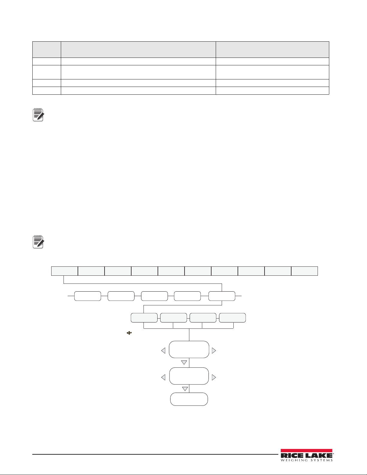
The default 480 print formats are shown in Table 7-2:
Note
Note
TIMDAT
ACCUM
SERIALSETPNT
PFRMAT
......
Display first 6
characters of format
Display and edit
active character and
ASCII value
Delete active
character
Scroll right in format string
Scroll left in format string
Increment ASCII value of active character
Decrement ASCII value of active character
Press to insert a space
before the active character
GFMT
NFMT
ACCFMT
SPFMT
MENU CONFIG FORMAT CALIBR PROGRM DIG IN ALGOUT PASWRD USBMEM TEST
Format Default Format String When Used
GFMT GROSS<G><NL2><TD><NL> Weigh mode – no tare in system
NFMT GROSS<G><NL>TARE<SP><T><NL>NET<SP2><N>
Weigh mode – tare in system
<NL2><TD><NL>
ACCFMT
ACCUM <A><NL><DA><SP><TI><NL>
Accumulator demand print format string
SPFMT <SCV><SP><SPM><NL> Setpoint print operation with PSHPRNT=ON
Table 7-2. GFMT and NFMT Formats
The <G2>, <N2> and <T2> tokens (Table 7-1) print the gross, net and tare weights in the units not currently
displayed on the indicator.
The 300 character limit of each print format string includes the output field length of the print formatting
tokens, not the token length. For example, if the indicator is configured to show a decimal point, the <G> token
generates an output field of 13 characters: the 10 character weight value (including decimal point), one space,
and a two-digit units identifier.
PT (preset tare) is added to the tare weight if tare was keyed in.
7.2 Customizing Print Formats
The following sections describe procedures for customizing the GFMT, NFMT, ACCFMT and SPFMT formats
using the front panel (PFORMT menu). See Figure 3-6 for print format menu structure.
7.2.1 Using the Front Panel
Use the PFORMT menu to customize the print formats.
Using the PFORMT menu (see Figure 3-6), edit the print format strings by changing the decimal values of the
ASCII characters in the format string.
Some characters cannot be displayed on the 480 front panel (see the ASCII character charts on page 72 and
page 73) and are shown as blanks. The
480 can send or receive any ASCII character; the character printed
depends on the particular ASCII character set implemented for the receiving device.
58 480 Legend Series
Figure 7-1. Print Format Menu
Page 66

8.0 Setpoints
Note
Important
Note
The 480 indicator provides eight configurable setpoints for control of both indicator and external equipment
functions. Setpoints can be configured to perform actions or functions based on specified parameter conditions.
Parameters associated with various setpoint kinds can, for example, be configured to perform functions (print, tare,
accumulate), to change the state of a digital output controlling indicator or external equipment functions, or to
make conditional decisions.
Weight-based setpoints are tripped by values specified in primary units only.
Firmware versions 1.00 and 1.01 require having a relay board installed for the setpoints to operate.
8.1 Batch and Continuous Setpoints
480 setpoints can be either continuous or batch.
Continuous setpoints are free-running; the indicator constantly monitors the condition of free-running setpoints at
each A/D update. The specified setpoint action or function is performed when the designated setpoint parameter
conditions are met. A digital output or function assigned to a free-running setpoint continuously changes state,
becoming active or inactive, as defined by the setpoint parameters.
Batch setpoint (BATSEQ = ON) is a digital output associated with a batch setpoint is act ive until the setpoint condition
is met. Then it is latched for the remainder of the batch sequence.
To use batch setpoints, set the batching (BATCHG) parameter on the setpoints (SETPTS) menu. This parameter
defines whether a batch sequence is automatic or manual. AUTO sequences repeat continuously after receiving a
single batch start signal, while MANUAL sequences only run through once for each Batch Start signal. The batch
start signal can be initiated by a digital input (set to BATSTR), or an EDP command (BATSTART).
For a setpoint to be used as part of a batch sequence, its batch sequence (BATSEQ) parameter must be set to ON. If
a setpoint is defined and enabled, but its Batch Sequence parameter is set to OFF, the setpoint operates as a
continuous setpoint even during batch sequences.
In applications that contain both batch setpoint routines and continuous setpoints, it is good practice to keep
continuous setpoints separate from the batch sequence.
Do not assign them the same digital output.
Batch and Continuous Setpoints 59
Page 67
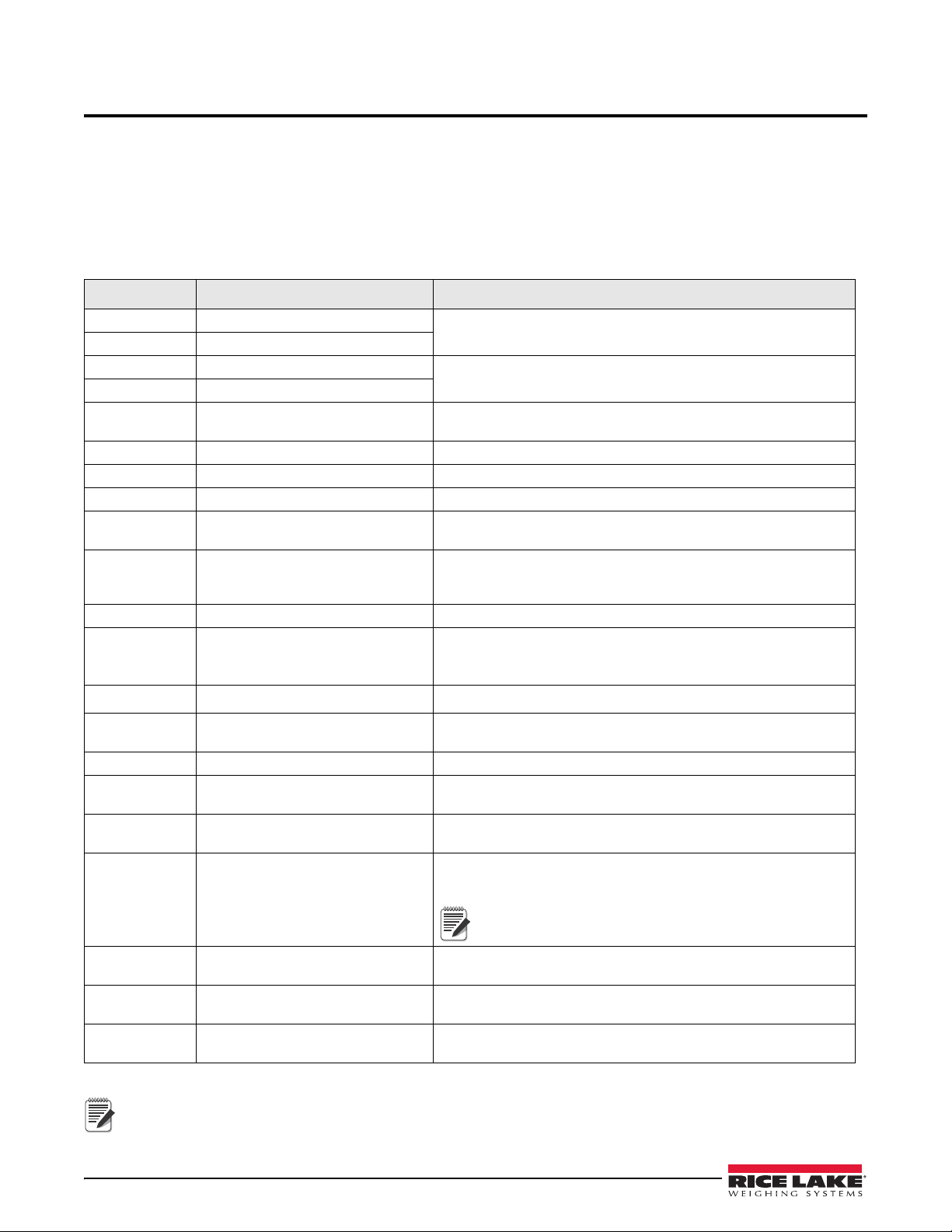
9.0 Appendix
Note
Note
9.1 Error Messages
The 480 indicator provides a number of error messages. When an error occurs, the message is shown on the
indicator LED display.
9.1.1 Displayed Error Messages
The 480 provides a number of front panel error messages to assist in problem diagnosis. Table 9-1 lists these
messages and their meanings.
Error Message Description Solution
E A/D A/D physical error Call Rice Lake Weighing Systems Service at 800-472-6703.
EEEROM EEPROM physical error
EVIREE Virgin EEPROM Use TEST menu to perform DEFLT (restore defaults) procedure, then
EPCKSM Parameter checksum error
EACKSM A/D calibration checksum error A/D converter requires recalibration. Call Rice Lake Weighing
EFCKSM Printer format checksum error Call Rice Lake Weighing Systems Service at 800-472-6703.
ELCKSM Load cell calibration checksum error Recalibrate load cells.
EIDATA Internal RAM checksum error Call Rice Lake Weighing Systems Service at 800-472-6703.
E REF A/D reference error A/D converter requires recalibration. Call Rice Lake Weighing
ERROR Internal program error Check configuration.
OVERFL Overflow error Weight value too large to be displayed.
- - - - - -
- - - - - -
- - - - - -
- - - - - -
RNGERR GRADS > 100,000
EEPERR EEPROM error Call Rice Lake Weighing Systems for service at 800-472-6703.
HINOFF? High offset Zero load at powerup is more than initial zero range (INIZR) setting of
LINOFF Low offset Zero load at power up is less than initial zero range (INIZR) setting of
NOBATT No battery The RTC lost time/date tracking at previous power off state due to
Gross > overload limit Gross value exceeds overload limit. Check configuration or signal
Gross < 20d behind zero Gross value is more than 20 divisions behind zero (OIML).
WVAL > 100,000
recalibrate load cells.
Systems Service.
Systems Service.
Call Rice Lake Weighing Systems Service if unable to clear error by
cycling power or if error recurs.
input level. Overload can be caused by input signal > 45 mV or
common mode voltage > 950 mV.
Only shows up in configuration mode.
calibration zero – remove the extra load.
calibration zero – add the missing load.
low battery or no battery condition. The printer, accumulator and
audit functions will fail to get time and date.
Refers to internal coin battery only, not the
rechargeable battery option.
EUCKSM Configuration checksum The checksum value of configuration has changed from that stored
in memory.
OIMLER OIML parameter error Parameter set incorrectly for use in the OIML mode.
Example: Primary units set for lb or oz.
EE-ACC Accumulator error Error with the accumulator such as attempting to display an
accumulated value greater than six digits.
Table 9-1. 480 Error Messages
Shorting the excitation voltage shuts the excitation voltage off. The only way to restore excitation voltage is to
cycle power.
60 480 Legend Series
Page 68

9.1.2 Using the XE EDP Command
The XE EDP command can be used to remotely query the 480 for the error conditions shown on the front panel.
The XE command returns two five digit numbers in the format:
xxxxx yyyyy
where xxxxx contains a decimal representation of any existing error conditions as described in Table 9-2.
If more than one error condition exists, the number returned is the sum of the values representing the error
conditions. For example, if the XE command returns the number 1040, this value represents the sum of an A/D
reference error (1024) and an A/D calibration checksum error (16).
The second number returned (
test for the error condition was run. For example, the value
yyyyy) uses the same bit assignments as shown in Table 9-2 to indicate whether the
yyyyy = 50815 represents the decimal equivalent of the
binary value 1100 0110 0111 1111. Using the bit assignments in Table 9-2, this value indicates all tests were run.
Error
Code
1
EEPROM Error 0000 0000 0000 0001
2
Virgin EEPROM 0000 0000 0000 0010
4
Config Parameter Checksum 0000 0000 0000 0100
8
Load Cell Checksum 0000 0000 0000 1000
16
32
64
128
256
512
1024
2048
4096
8192
16384
32768
0x10000 - 0x80000000
A/D Calibration Checksum 0000 0000 0001 0000
Print Formats Checksum 0000 0000 0010 0000
XA Internal RAM Error 0000 0000 0100 0000
External RAM Error 0000 0000 1000 0000
Reserved 0000 0001 0000 0000
ADC Physical Error 0000 0010 0000 0000
ADC Reference 0000 0100 0000 0000
Count Error 0000 1000 0000 0000
Reserved 0001 0000 0000 0000
Display Range 0010 0000 0000 0000
ADC Range 0100 0000 0000 0000
Gross Limit 1000 0000 0000 0000
Table 9-2. Error Codes Returned on XE Command
Description Binary Value
Reserved
9.2 Status Messages
Two EDP commands, P and ZZ, can be used to provide status about the indicator. These commands are described
in the following sections.
9.2.1 P EDP Command
The P EDP command returns the current displayed weight value, along with the units identifier. If the indicator is
in an underrange or overload condition, the weight value is replaced with
9.2.2 ZZ EDP Command
The ZZ EDP command can be used to remotely query which annunciators are currently displayed on the indicator
front panel. The ZZ command returns the currently displayed weight and a decimal number representing the LED
annunciators currently lit. The format of the returned data is:
wwwwww uu zzz
where wwwwww uu is the current displayed weight and units, and zzz is the annunciator status value (see Table 9-3).
If more than one annunciator is lit, ZZZ is the sum of the values representing the active annunciators.
&&&&&& (overload) or :::::: (underrange).
Status Messages 61
Page 69
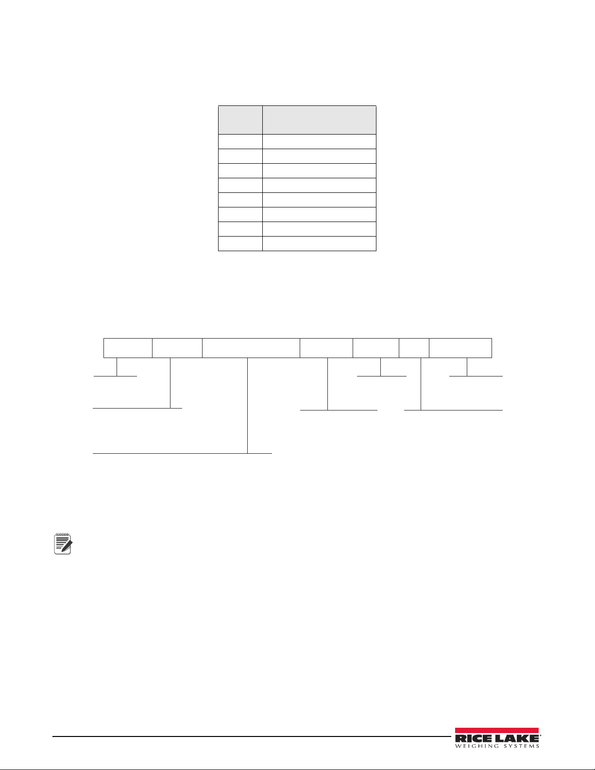
Example:
<STX> <POL> <wwwwwww> <UNIT> <G/N> <S> <TERM>
ASCII 02
decimal
Polarity:
<space> = Positive
<–> = Negative
Weight: 7 digits, right-justified, dummy
zeroes, decimal point with no leading
zeroes except for leading zero immediately
preceding the decimal point. Leading
zeroes transmitted as spaces.
L = pounds
K = kilograms
T = tons
G = grams
O = ounces
G = Gross
N = Net
Status:
<space> = valid
I = Invalid
M = Motion
O = Over/under range
Z = COZ
<CR> <LF>
or <CR>
Note
If the annunciator status value returned on the ZZ command is 145, the gr oss, standstill and lb annunciators are lit.
The number 145 represents the sum of the values for the standstill annunciator (128), gross mode annunciator (16)
and the lb/primary units annunciator (1).
Decimal
Val ue
1 lb/primary units
2kg/secondary units
4 Tare entered
8 Keyed tare entered
16 Gross
32 Net
64 Center of zero
128 Standstill
Annunciator
Table 9-3. Status Codes Returned on the ZZ Command
9.3 Continuous Data (Stream) Output Formats
When the trigger setting for COM-2 is set to one of the stream formats (STR1-STR5), or the Ethernet client or
server trigger setting is STRLFT or STRIND, data is continuously streamed from the appropriate port in one of the
five fixed formats that follow.
Figure 9-1. STR-1 Rice Lake Stream Data Format
Set format 5 if receiving device cannot read a status bit Z.
62 480 Legend Series
Page 70
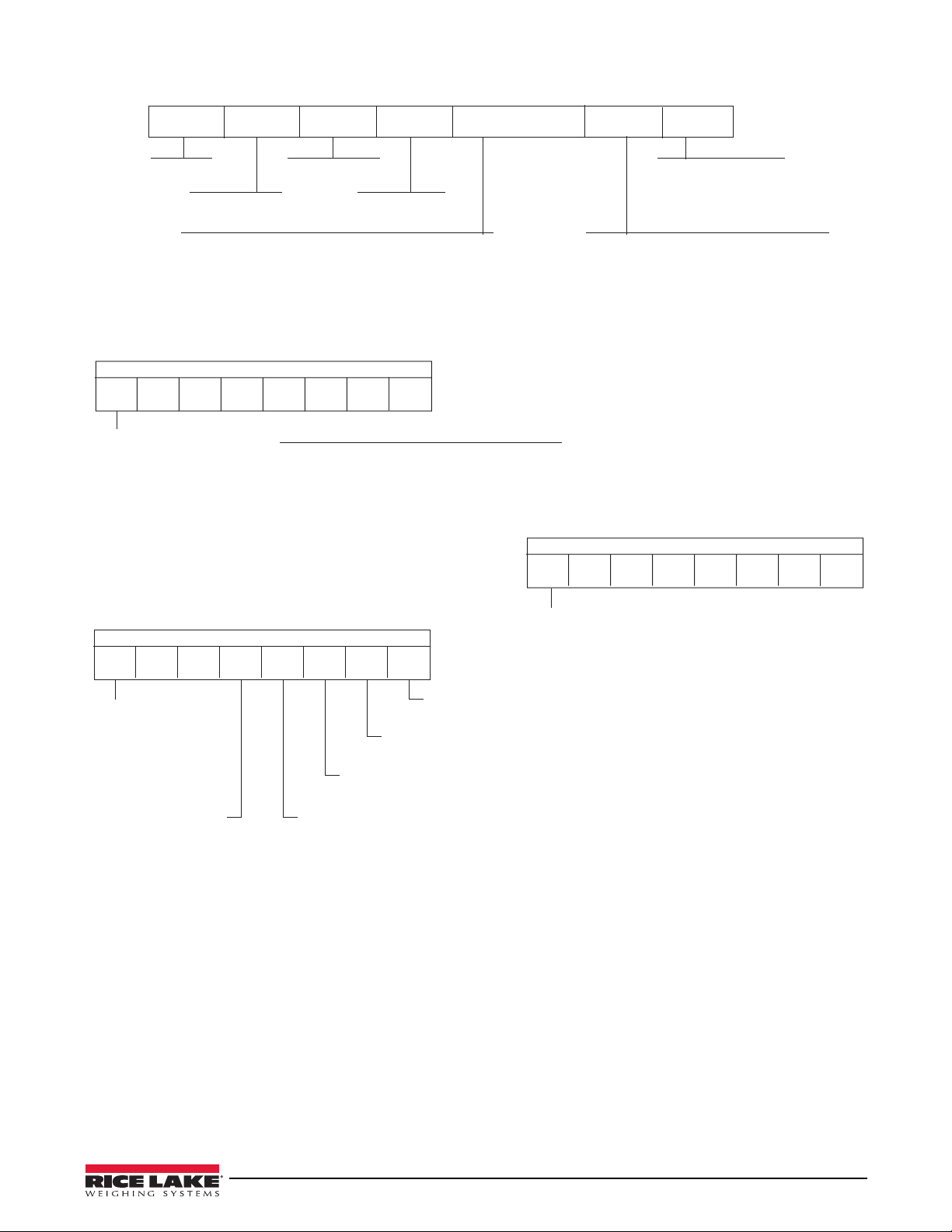
<STX> <SWA> <SWB> <SWC> <wwwwww> <tttttt> <CR>
STX (02h)
Status Word A
<CR> entered at end
of string.
Status Word B
Status Word C
MUL1 MUL0Parity
DP2 DP1 DP0 Fixed Zero/Dec. Pt. Location
0 0 0 x 100 (2 fixed zeroes)
0 0 1 x 10 (1 fixed zero)
0 1 0 x 1 (No decimal point)
0 1 1 x 0.1 (1 decimal place)
1 0 0 x 0.01 (2 decimal places)
1 0 1 x 0.001 (3 decimal places)
1 1 0 x 0.0001 (4 decimal places)
1 1 1 x 0.00001 (5 decimal places)
Disp. Div.
MUL1
MUL0
Multiplier
0 1 x 1
1 0 x 2
1 1 x 5
Even parity bit.
Requires EDP Port setup.
Status Word A:
Status Word C: ASCII 20h (space)
Even parity bit:
Requires EDP Port setup.
Status Word B:
0 = Gross Display Mode
1 = Net Display Mode
0 = Positive indicated weight value
1 = Negative indicated weight value
0 = In range
1 = Out of range
0 = Stable
1 = Motion
0 = lb
1 = kg
Even parity bit:
Requires EDP Port
setup.
Six digits, right justified, dummy zeros, decimal
point with no leading zeroes except for immediately
preceding the decimal point. Leading zeroes
transmitted as spaces.
Tare Weight: Six digits, right justified,
dummy zeros, decimal point with no
leading zeroes except for immediately
preceding the decimal point.
Leading zeroes transmitted as spaces.
76543210
DP2 DP1 DP010
Parity
76543210
1000000
Parity
76543210
10
Figure 9-2. STR-2 Toledo Stream Data Format
Continuous Data (Stream) Output Formats 63
Page 71
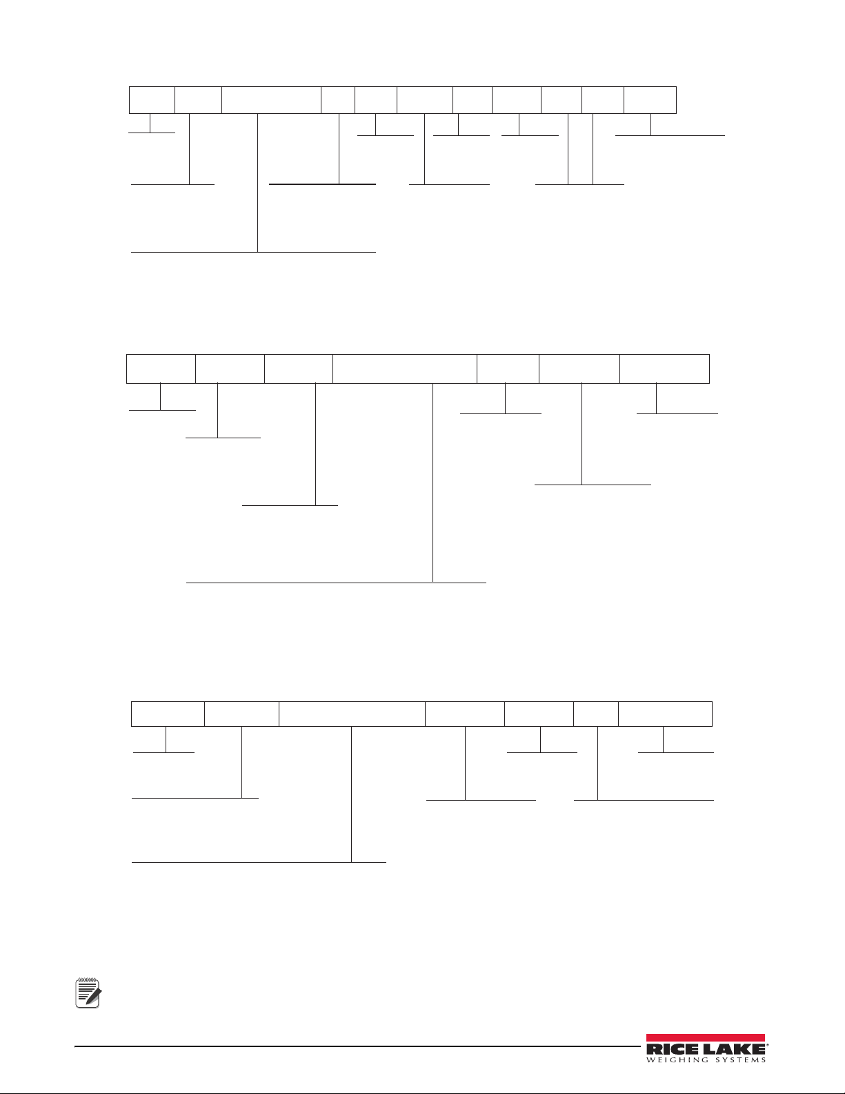
Figure 9-3. STR-3:Cardinal Stream Data Format
Carriage
Return
Polarity:
<+> for positive
"–" for negative
Six digits, right justified, floating decimal
(follows weight if not embeded),
leading zeroes are present.
g for Gross
n for Net
Hex value of <03>
is entered in string
lb = pound
kg = kilogram
g = gram
tn = ton (short)
t = ton (metric)
oz = ounce
<space> = none
Space
Character
<CR> <POL> <wwwwww> <S> <SP> <UNIT> <SP> <G/N> <SP> <SP> <ETX>
Space character
(2)
Space
Character
Status:
<space> = valid or invalid
m = motion
o = over/under range
Space
Polarity:
<+> for positive
"–" for negative
Six digits, right justified, floating decimal,
leading zeros are present
g for Gross
n for Net
<CR><LF>
or
<CR>
lb = pound
kg = kilogram
g = gram
tn = ton (short)
t = ton (metric)
oz = ounce
<space> = none
Space
<SP> <G/N> <POL> <wwwwww> <SP> <UNIT> <TERM>
<STX> <POL> <wwwwwww> <UNIT> <G/N> <S> <TERM>
ASCII 02
decimal
Polarity:
<space> = Positive
<–> = Negative
Weight: 7 digits, right-justified, dummy
zeroes, decimal point with no leading
zeroes except for leading zero immediately
preceding the decimal point. Leading
zeroes transmitted as spaces.
L = pounds
K = kilograms
T = tons
G = grams
O = ounces
G = Gross
N = Net
Status:
<space> = valid
I = Invalid
M = Motion
O = Over/under range
<CR> <LF>
or <CR>
Note
Figure 9-4. STR-4 Weightronix Stream Data Format
Port 1 cannot be set to stream.
64 480 Legend Series
Figure 9-5. STR-5: Consolidated Controls Stream Data Format
Page 72
9.4 Local/Remote Operation
For systems that require two locations, local/remote support provides function equivalent to that of a Legal for
Trade remote display with keypad. Scale data from the local indicator is also displayed at the remote unit, and
keypad input from the remote allows transactions to be initiated from either the local or remote unit.
To configure for local/remote operation, set STREAM to local or remote. Once the local unit scale has been
configured, use the SERIAL menu, serial commands or Revolution to set the serial parameters for local/remote
operation. See Table 3-3 on page 26 for comport option s.
Serial
Configuration
Parameter
STREAM Local Stream Continuous Data Remote Sets indicator to display the
COM2.TRIGER Select STR-1 Streams the local unit
COM2.BAUD Local and remote must match
COM2.ECHO OFF OFF
Parameter Value Function Parameter Value Function
Printing operation can be performed at the remote unit and/or at the local unit. When the operator presses the
Local Unit Remote Unit
weight data sent from the
Local Unit.
weight data to the
remote unit
Table 9-4. Local/Remote Configuration
Select STR-1 Transmits demand key
presses, zero, gross/net,
tare, units
Print
key at the local unit, a printing ticket will be issued only locally. When the operator presses the Print key at the
remote unit, print will only occur at the remote unit.
9.5 Audit Trail Support
Audit trail support provides tracking information for configuration and calibration events. To prevent potential
misuse, all configuration and calibration changes are counted as change events.
Audit trail information can be printed from Revolution or by sending the DUMPAUDIT serial command. See
Figure 3-1 on page 22. Revolution can be used to display audit trail information. The audit trail display includes the
legally relevant (LR) version number (firmware version for the code that provides audit trail information), a
calibration count and, if REGULA=NTEP or Canada, a configuration count. The exact format of the information
shown depends on the regulatory agency specified for the REGULA (PROGRM menu) parameter.
See Section 1.8.10 on page 7 for steps to view the Audit Trail.
For NTEP and Measurement Canada modes, there are two numbers displayed: configuration and calibration. The
configuration number tracks changes to the legally relevant configuration parameter changes. The calibration
number tracks changes to the scale calibration.
In OIML mode, the only number displayed is audit trail. The audit trail number is incremental for any legally
relevant configuration parameter changes and all calibration changes. The last date the scale was calibrated is also
displayed.
9.6 Sleep Mode
Firmware version 1.03 and newer of the 480 features a sleep mode. It is designed to place the indicators into a low
power mode to reduce power consumption.
The sleep mode will only activate if the indicator is operating on its internal optional battery. If connected to
external AC power, the indicator will not go into sleep mode regardless of the parameter settings.
The indicator will enter the sleep mode, after the time specified in the
detected and the displayed weight is below the weight threshold (
disables the sleep mode.
Standby
While in sleep mode, at a time specified in the standby (STDBY) parameter, the indicator wakes up for about 0.5
seconds. The range of the standby time is 1 to 60 seconds. During the awake time, it checks for a change in weight
greater than the display division threshold (DDTHRH), or if the weight has gone above the weight threshold
(WGTHRH). It also checks to see if a key is being pressed and performs zero tracking.
SLEEP parameter, when no keypad activity is
WGTHRH). Setting the sleep parameter to never
Local/Remote Operation 65
Page 73

Example:
Note
If the standby parameter set to 1 second, the weight threshold to 100, and the display division threshold is set to
10d, once in sleep mode, the indicator will wake up every second for about half a second to check to see if a key is
being pressed, the weight threshold is over 100 (WGTHRH), or the weight has change more than 10d (DDTHRH)
since the last time it checked.
Setting the standby parameter to a higher value reduces the amount of time the indicator is awake, this will increase
battery life.
OFF setting stops the indicator from waking up. The only way to wake up the indicator is to press the Power key.
An
The Power key is the only key that will wake the indicator, unless the Standby parameter is set to any setting
other than NONE. Then any key press will work to wake the indicator from standby.
9.7 Internal Battery Option
In Firmware version 1.03 and later, an optional internal rechargeable Li-ion battery is available. The battery can
replace the AC power when needed. Typical run time is 12 hours (single load cell, no options, with LED display).
The amount of time the indicator will operate on the battery depends on:
• Type of display (LED)
• If sleep mode is used or not
• How may load cells are attached
• What options are installed
The battery is automatically charged when the indicator is connected to AC power. It automatically switches to
battery power if the AC power is removed. The battery is designed to only be charged by connecting to AC power.
When operating on battery power, the indicator features a sleep mode that allows the indicator to go into a low
power mode. Using the sleep mode helps improve battery life. See Section 9.6 for more information about the sleep
mode.
When the battery life reaches 5-10 percent of capacity, the
less than 5 percent, it will flash faster, at 0 percent, the indicator will turn off. Battery char ge time is approximately
16 hours to 100 percent.
Lo Bat flashes on the display. When the battery life is
9.8 USB Option
In firmware version 1.03 and later, an optional Ethernet/USB board is supported.
The USB connection is capable of being either of the following:
• USB device (connected to a PC and appearing as an available communication port)
• USB host interface to a flash drive
• USB interface to printer
The mode of the USB option is selected in the User Menu.
9.8.1 HOST
When set to HOST mode, the USB port can be connected to a USB connection on a PC. An HCC Driver is required
on the PC.
The HCC driver is available on a CD (PN 171153) that is included with the USB/Ethernet Option. Use the
documentation (PN 171152) for the option to install the driver on the PC.
When connected to a PC, the connection will appear to applications as another serial communications port. Using
the USB trigger parameter in the 482 user menu, it is possible to set the port to act as both a serial command port
and demand print port (
used through the USB HOSTPC port.The USB port cannot be used to stream data.
9.8.2 Flash Drive
When set to Drive mode, the USB port can be connected to a flash drive to allow the upload and download of the
indicator configuration parameters. The data is written to the drive in a FA T32 system format; no special drivers are
required.
To use with a flash drive, first configure the
the drive, or loading it from the drive, can only be done in the configuration menu.
DEMAND), or as a serial command port only (COMAND). All EDP serial commands can be
USB parameter in the user menu to DRIVE. Saving the configuration to
66 480 Legend Series
Page 74

Save the Configuration
1. Attach a flash drive to the USB port.
2. Enter the configuration menu and navigate go to
3. Press , then press or to select
4. Press the
Tare key. A copy of the configuration DUMPALL, will be written to the drive in an ASCII text
SAVE. See Section 3.2.9 on page 43.
USBMEM. See Section 3.2 on page 32.
file with the name “480_<UID>.txt”, where <UID> is replaced with the unit ID configured in the indicator.
Load a Configuration File
1. Install the file on the flash drive. The file can be either of two formats, a configuration dumpall text file, or
a configuration file created by the Revolution indicator configuration utility. The file name must be
“480_<UID>.txt” for a text file, or “480_<UID>.rev” for a Revolution file, where <UID> is the currently
configured Unit ID of the indicator.
2. Attach the flash drive to the USB port.
3. Enter the configuration menu and navigate go to
USBMEM. See Section 3.2 on page 32.
4. Press , then press or to select LOAD. See Section 3.2.9 on page 43
5. Press the
Tare key. If a file is found on the flash drive with a <UID> that matches that currently in the
indicator, it will be loaded. If the loading of the file fails for any reason, an error will be displayed.
Edit and Save File on Flash Drive with Revolution
1. To open the file, select the appropriate 480 module and open it.
2. Use the Import function in the File menu to import the configuration parameters into Revolution.
9.8.3 USB Printing
When set to PRINTR mode, the USB port can be connected to a USB printer using an appropriate USB cable.
To configure (see Section 3.1.4 on page 29):
1. Set the USB port to
2. Set the trigger to
3. Press the
Print key or call a remote print command to print to the USB printer.
PRINTR.
DEMAND.
9.9 Ethernet Option
In firmware version 1.03 and later, an optional Ethernet/USB board is supported.
With the Ethernet option installed, the 480 can either be connected directly to a PC via the Ethernet connection, or
to an Ethernet network.
The 480 Ethernet option will support two simultaneous connections, one as a server, the other a client. It can be set
up with a static, or DHCP-provided IP address. Both ports can be used to communicate to the indicator using all the
available serial EDP commands. Both ports can be set to print on demand and can stream data.
The server port has a configurable TCP port number, and can accept a single remote client connection.
The client port can be configured to connect to a remote server’s IP and TCP port number upon power up, or
whenever there is data to send.
Connection is made via a RJ45 connector inside the indicator on the Ethernet/USB option board.
For details on all the configurable parameters for the optional Ethernet ports, see Section 3.1.3 on page 28.
Ethernet Option 67
Page 75

9.10 Conversion Factors for Secondary Units
Note
The 480 has the capability to mathematically convert a weight into many different types of units and instantly
display those results with a press of the
Secondary units can be specified on the Format menu using the
Multipliers are preconfigured within the indicator.
Ensure that the secondary decimal point position is set appropriately for the scale capacity in the secondary
units. If the converted value requires more digits than are available, the indicator will display an overflow
message (OVERFL).
For example, if the primary units are short tons, secondary units are pounds, and the secondary decimal point is set to
8888.88, the indicator will overflow if five tons or more are applied to the scale. With 5 tons applied, and a conversion
factor of 2,000, the secondary units display needs five digits to the left of the decimal point to display the 10,000 pound
secondary units value.
Unit key.
SECNDR parameter.
9.11 Digital Filtering (DIGFIL)
Digital filtering is used to create a stable scale reading in challenging environments. The 480 (firmware version
1.03 and later) allows selection of
for no filtering.
The A/D sample rate must be selected first (see Section 9.11.1). Then select the type of digital filter using the
DIGFIL parameter.
9.11.1 Sample Rate (SMPRAT)
The A/D sample rate is the number of weight readings the indicator takes per second (
20 or 40 Hertz, or readings per second.
Set the A/D sample rate to the lowest setting required f or the application. Lo wer settings result in better stability, so
5 Hertz is more stable than 40 Hertz.
Adaptive Filtering (see Section 9.11.2), Rolling Filtering (see Section 9.11.3) or OFF
SMPRAT). This can be 5, 10,
9.11.2 Adaptive Filter
The adaptive filter has two settings, sensitivity (
AFSENS) and threshold (AFTHRH). It maintains a running average
of the A/D readings when the weight change remains less than the defined Threshold value. The filter
automatically applies less value to each successive A/D reading the longer the weight change is less than the
Threshold value. The amount of value given to the most recent A/D reading is determined by the sensitivity setting.
Adaptive Filter Sensitivity (AFSENS)
Adaptive filter sensitivity (AFSENS) can be set to HEAVY, MEDIUM or LIGHT. A heavy setting will result in an output
that is more stable to weight changes, than that of light. However , small changes in weight data (a few grads) on the
scale base will not be seen as quickly.
If the difference in typical subsequent weight values on the scale will only be a few grads, use a light setting. On a
truck scale where the changes in subsequent weight values will be 100s of grads, a heavy setting will be more
appropriate. When the weight has not exceeded the Threshold (
approximately 30 A/D cycles for
Adaptive Filter Threshold (AFTHRH)
LIGHT, 90 A/D cycles for MEDIUM and 180 A/D cycles for HEAVY.
AFTHRH) setting, the effective response is
The adaptive filtering threshold (AFTHRH) should be set for the amount of observed instability in the system. This
parameter can be set in the range of 0 to 99999 and is entered as a weight value. When a new sampled weight value
is acquired, the adaptive filter compares the new value to the previous (filtered) output value.
If the difference between the new value and the previous output value is greater than the
AFTHRH parameter the
adaptive filter is reset to the new weight value.
If the difference between the new value and the previous output value is less than the
AFTHRH parameter, the two
values are averaged together using a weighted average. The weighted average is based on the amount of time the
system has been stable, and selected
AFSENS sensitivity.
With the adaptive filter threshold set at zero, determine the amount of instability that is present. Enter this amount
of weight instability to set the threshold of the adaptive filter. The adaptive filter is set to
OFF the AFTHRH
parameter is set to zero.
68 480 Legend Series
Page 76

9.11.3 Rolling Averaging Filter
The rolling averaging filter uses mathematical averaging with three stages. These configurable stages control the
effect of a single A/D reading on the displayed weight. When an A/D reading is encountered that is outside a
predetermined band, the rolling averaging filter is overridden and the display jumps directly to the new value.
Filter Stages (RFSTG1-3)
The filter stages can each be set to a value of 1 to 64. The value assigned to each stage sets the number of readings
received from the preceding filter stage before averaging. Setting the filter stages to 1 effectively disables the
rolling filter.
A rolling average is passed to successive filtering stages for an overall filtering effect that is effectively a weighted
average of the product of the values assigned to the filter stages (
corresponding to the sum of the values (
Filter Sensitivity (RFSENS) and Threshold (RFTHRH)
RFSTG1 + RFSTG2 + RFSTG3).
RFSTG1 x RFSTG2 x RFSTG3) within a time frame
The rolling averaging filter can be used by itself to eliminate vibration effects, but heavy filtering also increases
settling time. The
RFSENS and RFTHRH parameters can be used to temporarily override filter averaging and
improve settling time.
RFSENS specifies the number of consecutive A/D readings that must fall outside the filter threshold
•
(RFTHRH) before filtering is suspended.
•
RFTHRH sets a threshold value, in display divisions. When the specified number of consecutive A/D
readings (RFSENS) fall outside of this threshold, filtering is suspended. Set RFTHRH to NONE to turn off the
filter override.
Rolling Averaging Filter Parameters
1. In setup mode, set the rolling filter stage parameters (RFSTG1-3) to 1.
2. Set
RFTHRH to NONE.
3. Return to weigh mode.
4. Remove all weight from the scale, then watch the indicator to determine the magnitude of vibration effect
on the sc
5. Record the weight below which all but a few readings fall. This value is used to calculate the
ale.
RFTHRH
parameter in step 8.
Example – if a heavy-capacity scale (10000x5lb) produces vibration-related readings of up to 50 lb, with
occasional spikes to 75 pound, record 50 pound as the threshold weight value.
6. Place the indicator in setup mode and set the filter stage parameters (
ef
fects on the scale (leave
7. Find the lowest effect value for the
If needed, the rolling filter cutout sensitivity (
RFTHRH set to NONE).
RFSTG1-3 parameters.
RFSENS) and the rolling filter cutout threshold (RFTHRH) can be used
RFSTG1-3) to eliminate the vibration
to reset the averaging filter so the response to a rate change is faster.
8. Calculate the
div
isions (
RFTHRH parameter value by converting the weight value recorded in step 5 to display
Threshold_Weight_Value / Display_Divisions).
In the example in step 5, with a threshold value of 50 pound, and a display divisions value o f 5 pound,
RFTHRH should be set to 10 display divisions.
9. Set the
RFSENS parameter high enough to ignore transient peaks. Longer transients (typically caused by
lower vibration frequencies) will cause more consecutive out-of-band readings, so RFSENS should be set
higher to counter low frequency transients.
s
Digital Filtering (DIGFIL) 69
Page 77

9.12 Analog Output Calibration
Note
Note
The following calibration procedure requires a multimeter to measure voltage or current output from the analog
output module. See Figure 3-15 for analog output menu structure.
The analog output must be calibrated after the indicator itself has been configured (see Section 3.0) and
calibrated (see Section 4.0).
1. Enter configuration mode and go to the ALGOUT menu (see Figure 3-15).
• S et source to
•Set
•Set
•Set
OFFSET to 0% for 0–10V/0-20mA output, 20% for 2-10V/4–20 mA output
MIN to lowest weight value to be tracked by the analog output
MAX to highest weight value to be tracked by the analog output
Calibrate the minimum weight value for 0 mA, even if a 4-20 mA output will be used. After the calibration is
complete, select the 20% offset.
If set to a 20% offset, the lowest value tracked will be 4 mA. To use a value lower than 4mA, use the 0-20 mA
setting.
2. Connect multimeter to analog output:
• For voltage output, connect voltmeter leads to pins three and four
• For current output, connect ammeter leads to pins one and two
3. Adjust the zero calibration: Scroll to the
multimeter. Press or to select the digit to edit and or to adjust the value of selected (flashing)
digit to set the zero value.
4. Adjust span calibration: Scroll to the
Press or to select the digit to edit and or to adjust the value of selected (flashing) digit to set the
span value.
5. Final zero calibration: Return to the
Press or to select the digit to edit and or to adjust the value of selected (flashing) digit to set the
zero value.
6. Return to weigh mode. Analog output function can be verified using test weights.
GROSS or NET, depending on the weight value to be tracked by the analog output
TWZERO parameter. Check voltage or current reading on
TWSPAN parameter. Check voltage or current reading on multimeter.
TWZERO parameter and verify that the zero calibration has not drifted.
9.13 Test Mode
In addition to weigh and setup modes, test mode provides a number of diagnostic functions for the 480, including:
• Display raw A/D count
• Reset configuration parameters to default values
• Number of weighments over threshold
• View the state of the digital inputs
• Control the state of the digital outputs
• Test the analog output
1. Enter configuration mode by removing the setup switch access screw from the back of the enclosure.
2. Insert a non-conductive tool into the access hole to press the configuration switch. Indicator display
changes to show
3. Navigate over to
Figure 3-18 shows the Test Menu structure and Table 3-19 summarizes the test menu functions.
CONFIG.
TEST and then down into the TEST menu.
70 480 Legend Series
Page 78
9.14 Regulatory Mode Functions
Note
Regulatory
Parameter
NTEP
Canada
OIML
None
Weight On
Scale
Zero
Negative
Positive
Zero
Negative
Positive
Zero
Negative
Positive
Zero
Negative
Positive
Tare I n
System
No “000000” Zero
Yes Clear tare Zero
No No action Zero
Yes Clear tare Zero
No Tare Zero
Yes Tare Zero
No “000000” Zero
Yes Clear tare Clear tare
No No action Zero
Yes Clear tare Clear tare
No Tare Zero
Yes No action Clear tare
No “000000” Zero
Yes Clear tare Zero & Clear tare
No No action Zero
Yes Clear tare Zero & Clear tare
No “000000” Zero
Yes Tare Z ero & Clea r Tare
No “000000” Zero
Yes Clear tare Clear tare
No No action Zero
Yes Clear tare Clear tare
No Tare Zero
Yes Clear tare Clear tare
Front Panel
Key Tare
Table 9-5. Tare and Zero Key Functions for REGULA Parameter Settings
Front Panel
Key Zero
At zero weight, the push-button tare will prompt for a keyed tare when tare function is set to keyed or both.
Regulatory Mode Functions 71
Page 79

9.15 ASCII Character Chart
Use the decimal values for ASCII characters listed in Tables 9-6 and 9-7 when specifying print format strings on
the 480 PFORMT menu. The actual character printed depends on the character mapping used by the output device.
The 480 can send or receive any ASCII character value (decimal 0–255), but the indicator display is limited to
numbers, upper-case, unaccented letters and a few special characters. See Section 9.16 for information about the
480 LED display.
Control ASCII Dec Hex ASCII Dec Hex ASCII Dec Hex ASCII Dec Hex
Ctrl-@ NUL 00 00 space 32 20 @ 64 40 ` 96 60
Ctrl-A SOH 01 01 ! 33 21 A 65 41 a 97 61
Ctrl-B STX 02 02 “ 34 22 B 66 42 b 98 62
Ctrl-C ETX 03 03 # 35 23 C 67 43 c 99 63
Ctrl-D EOT 04 04 $ 36 24 D 68 44 d 100 64
Ctrl-E ENQ 05 05 % 37 25 E 69 45 e 101 65
Ctrl-F ACK 06 06 & 38 26 F 70 46 f 102 66
Ctrl-G BEL 07 07 ’ 39 27 G 71 47 g 103 67
Ctrl-H BS 08 08 ( 40 28 H 72 48 h 104 68
Ctrl-I HT 09 09 ) 41 29 I 73 49 i 105 69
Ctrl-J LF 10 0A * 42 2A J 74 4A j 106 6A
Ctrl-K VT 11 0B + 43 2B K 75 4B k 107 6B
Ctrl-L FF 12 0C , 44 2C L 76 4C l 108 6C
Ctrl-M CR 13 0D - 45 2D M 77 4D m 109 6D
Ctrl-N SO 14 0E . 46 2E N 78 4E n 110 6E
Ctrl-O SI 15 0F / 47 2F O 79 4F o 111 6F
Ctrl-P DLE 16 10 0 48 30 P 80 50 p 112 70
Ctrl-Q DC1 17 11 1 49 31 Q 81 51 q 113 71
Ctrl-R DC2 18 12 2 50 32 R 82 52 r 114 72
Ctrl-S DC3 19 13 3 51 33 S 83 53 s 115 73
Ctrl-T DC4 20 14 4 52 34 T 84 54 t 116 74
Ctrl-U NAK 21 15 5 53 35 U 85 55 u 117 75
Ctrl-V SYN 22 16 6 54 36 V 86 56 v 118 76
Ctrl-W ETB 23 17 7 55 37 W 87 57 w 119 77
Ctrl-X CAN 24 18 8 56 38 X 88 58 x 120 78
Ctrl-Y EM 25 19 9 57 39 Y 89 59 y 121 79
Ctrl-Z SUB 26 1A : 58 3A Z 90 5A z 122 7A
Ctrl-[ ESC 27 1B ; 59 3B [ 91 5B { 123 7B
Ctrl-\ FS 28 1C < 60 3C \ 92 5C | 124 7C
Ctrl-] GS 29 1D = 61 3D ] 93 5D } 125 7D
Ctrl-^ RS 30 1E > 62 3E ^ 94 5E ~ 126 7E
Ctrl-_ US 31 1F ? 63 3F _ 95 5F DEL 127 7F
72 480 Legend Series
Table 9-6. ASCII Character Chart (Part 1)
Page 80

ASCII Dec Hex ASCII Dec Hex ASCII Dec Hex ASCII Dec Hex
Ç 128 80 á 160 A0 192 C0 224 E0
ü 129 81 í 161 A1 193 C1 ß 225 E1
é 130 82 ó 162 A2 194 C2 226 E2
â 131 83 ú 163 A3 195 C3 227 E3
ä 132 84 ñ 164 A4 196 C4 228 E4
à 133 85 Ñ 165 A5 197 C5 229 E5
å 134 86 ª 166 A6 198 C6 μ 230 E6
ç 135 87 º 167 A7 199 C7 231 E7
ê 136 88 ¿ 168 A8 200 C8 232 E8
ë 137 89 169 A9 201 C9 233 E9
è 138 8A ¬ 170 AA 202 CA 234 EA
ï 139 8B 1/2 171 AB 203 CB 235 EB
î 140 8C 1/4 172 AC 204 CC 236 EC
ì 141 8D ¡ 173 AD 205 CD 237 ED
Ä 142 8E « 174 AE 206 CE 238 EE
Å 143 8F » 175 AF 207 CF 239 EF
É 144 90 176 B0 208 D0 240 F0
æ 145 91 177 B1 209 D1 ± 241 F1
Æ 146 92 178 B2 210 D2 242 F2
ô 147 93 179 B3 211 D3 243 F3
ö 148 94 180 B4 212 D4 244 F4
ò 149 95 181 B5 213 D5 245 F5
û 150 96 182 B6 214 D6 ÷ 246 F6
ù 151 97 183 B7 215 D7 ˘ 247 F7
ÿ 152 98 184 B8 216 D8 ° 248 F8
Ö 153 99 185 B9 217 D9 • 249 F9
Ü 154 9A 186 BA 218 DA 250 FA
¢ 155 9B 187 BB 219 DB 251 FB
£ 156 9C 188 BC 220 DC 252 FC
¥ 157 9D 189 BD 221 DD
²
253 FD
Pts 158 9E 190 BE 222 DE 254 FE
ƒ 159 9F 191 BF 223 DF 255 FF
Table 9-7. ASCII Character Chart (Part 2)
ASCII Character Chart 73
Page 81
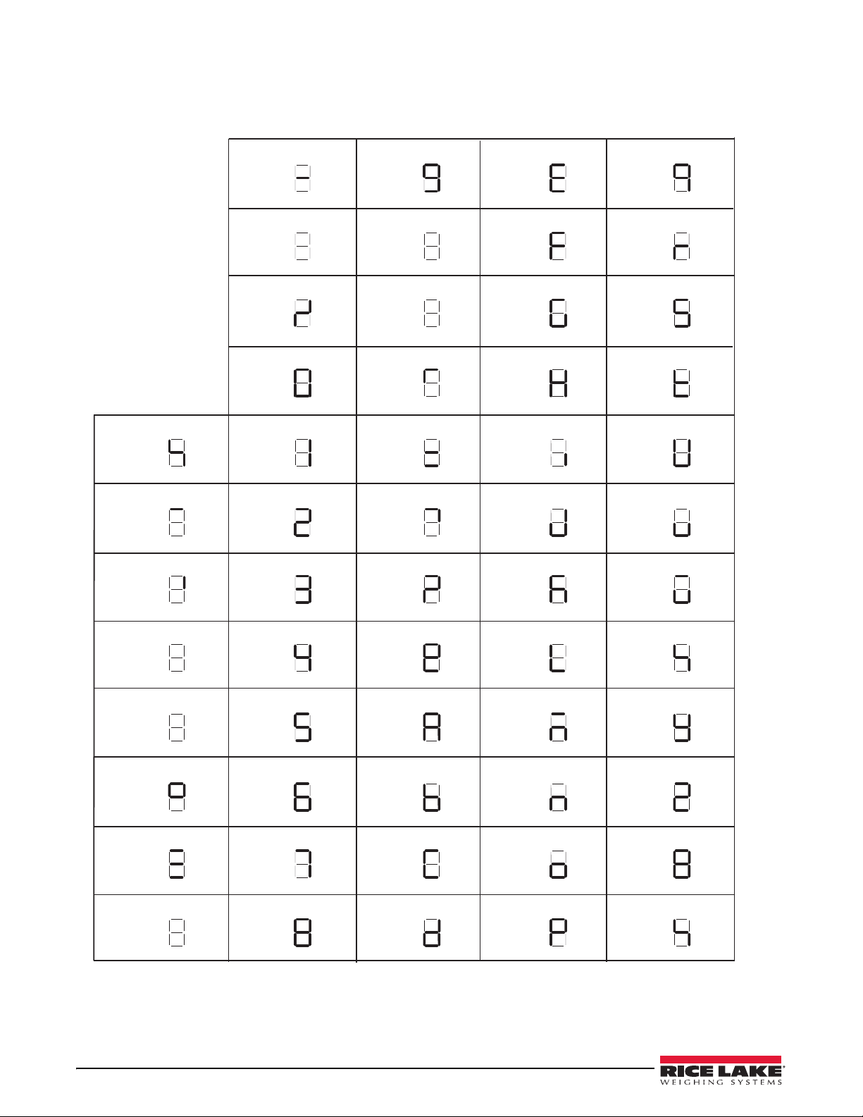
9.16 Front Panel Display Characters
-9EQ
.:FR
/;GS
0<HT
1=
%IU
&2>JV
‘
3?KW
(4@LX
)5AMY
*6BNZ
+7CO[
,8DP\
.
Figure 9-6 shows the seven-segment LED character set used to display alphanumeric characters on the 480 front
panel.
Figure 9-6. 480 Display Characters
74 480 Legend Series
Page 82
9.17 Specifications
Model Numbers
United States 480-2A/480Plus-2A (NEMA Type 5-15)
International 480-2A/480Plus-2A (CEE 7/7)
Power – AC
Line Voltages 90 to 264 VAC
Frequency 50 or 60 Hz
Power Consumption 70 mA @ 115 VAC (8W)
35 mA @ 230 VAC (8W)
Fusing 2.5 A 5 x 20 mm fuse
Analog Specifications
Full Scale Input Signal Up to 35 mV
Excitation Voltage 5 ± 0.1VDC
Sense Amplifier Differential amplifier with
4- and 6-wire sensing
Analog Signal
Input Range Up to 7 mV/V
Analog Signal
Sensitivity 0.1 V/graduation minimum
0.5 V/grad recommended
Local Resistance 35-1140
Noise (ref to input) 0.5 V p-p 3
Internal Resolution 523,376 counts
Display Resolution 100,000 dd
Measurement Rate 37 measurements/sec
Input Sensitivity 38 nV per internal count
System Linearity Within 0.01% of full scale
Zero Stability 13 nV/°C
4
Span Stability 13 ppm/°C
5
Calibration Method Software, constants stored in EEPROM
Common Mode
Voltage AGND + 250mV V min
6
Excitation - 250 mV V max
Rejection 120 dB minimum @ 50 or 60 Hz
Normal Mode
Rejection 100 dB minimum @ 50 or 60 Hz
Input Overload -0.3 V to Excitation +0.3 V 7
RFI Protection Signal, excitation, and sense lines
protected by capacitor bypass and
ESD suppressors
Analog Output (Optional)
Type Fully isolated, voltage or current
output,16-bit resolution.
Voltage output 0 –10 VDC
Voltage load resistance 1K minimum
Current output 0–20 mA or 4–20 mA
Current loop resistance 1200 maximum
Digital Specifications
Microprocessor ARM Cortex M3 STM32F103ZET6
Digital Filters Adaptive Filter and Rolling Averaging
Filter; software selectable
Digital I/O (Optional)
Type Fully isolated
Digital Inputs 2 or 4 inputs, Opto isolated, 5 to 24
VDC input, active high
Digital Outputs 4 or 8 dry-contact relays
Up to 30VDC at 2A current
Serial Communications
Com 1 Full duplex RS-232
Com 2 Full duplex RS232, or output only
Active 20mA current loop.
Both Ports 1200 to 38400 bps; 7 or 8 data bits;
even, odd, or no parity; 1 or 2 stop bits
Only Com 2 can be set to stream.
Operator Interface
Display 6-digit LED display. 7-segment, 0.8 in
(20 mm) digits
LED annunciators Gross, net, center of zero, standstill, lb/
primary units, kg/secondary units, T,
PT
Keypad 7-key (19 key for Plus Model) flat
membrane panel
Environmental
Operating Temperature–10 to +40°C (legal);
–10 to +50°C (industrial)
Storage Temperature –25 to +70°C
Humidity 0–95% relative humidity
Enclosure
Enclosure Dimensions 9.5 in x 6 in x 2.75 in
24 cm x 15 cm x 7 cm
Weight 6 lb
Rating/Material 4X
Certifications and Approvals
NTEP
CoC Number 12-123
Accuracy Class III/IIIL n
max
: 10 000
OIML R76/2006-NL1-12.48
European Test Certificate TC8322
European EC Type-Approval T5692
Accuracy Class III n
max
: 10 000
Measurement Canada
Approval AM-5892
Accuracy Class III/IIIHD n
max
: 10 000
Note
•
N
A
T
I
O
N
A
L
C
O
N
F
E
R
E
N
C
E
•
O
N
W
E
I
G
H
T
S
A
N
D
M
E
A
S
U
R
E
S
1
Calculated based on 350x 10 load cells, 1x I/O card, 1x Analog card, 7 segment display.
2
The indicator was tested for EMC with a 380 load cell; the maximal approved impedance is therefore 380 x 3 = 1140k.
3
Measured during EMC tests per OIML R76-2006 (10v/m) without any digital filter in s/w; sampling rate was 4.7Hz.
4
Measured on an indicator with a simulator; the nominal zero stability of the ADC is 5 nV/°C.
5
Measured on an indicator with a simulator; the nominal span stability of the ADC is 1ppm/°C.
6-7
Based on the internal ADC specifications.
8
Based on the internal DAC specifications.
Specifications 75
Page 83

76 480 Legend Series
Page 84

Page 85

January 14, 2016
230 W. Coleman St. • Rice Lake, WI 54868 • USA
U.S. 800-472-6703 • Canada/Mexico 800-321-6703 • International 715-234-9171 • Europe +31 (0)26 472 1319
www.ricelake.com www.ricelake.mx www.ricelake.eu www.ricelake.co.in m.ricelake.com
Rice Lake Weighing Systems is an ISO 9001 registered company.
© Rice Lake Weighing Systems Specifications subject to change without notice.
PN 119201 Rev K
 Loading...