

Page 1

480 Legend Series
Digital Weight Indicator
Version 1.05
Operation Manual
PN 163374 Rev DOctober 3, 2019
Page 2

An ISO 9001 registered company
© Rice Lake Weighing Systems. All rights reserved.
®
Rice Lake Weighing Systems
is a registered trademark of
Rice Lake Weighing Systems.
All other brand or product names within this publication are trademarks or registered
trademarks of their respective companies.
All information contained within this publication is, to the best of our knowledge, complete and
accurate at the time of publication. Rice Lake Weighing Systems reserves the right to make
changes to the technology, features, specifications and design of the equipment without notice.
The most current version of this publication, software, firmware and all other product updates
can be found on our website:
www.ricelake.com
Page 3

Contents
Technical training seminars are available through Rice Lake Weighing Systems.
Course descriptions and dates can be viewed at www.ricelake.com/training
or obtained by calling 715-234-9171 and asking for the training department.
Contents
1.0 Introduction ................................................................................ 1
1.1 Safety. . . . . . . . . . . . . . . . . . . . . . . . . . . . . . . . . . . . . . . . . . . . . . . . . . . . 2
1.2 Operating Modes . . . . . . . . . . . . . . . . . . . . . . . . . . . . . . . . . . . . . . . . . . . 3
1.3 Front Panel Display . . . . . . . . . . . . . . . . . . . . . . . . . . . . . . . . . . . . . . . . . 3
1.3.1 Key Functions . . . . . . . . . . . . . . . . . . . . . . . . . . . . . . . . . . . . . . . . . . . 4
1.3.2 Annunciator Functions . . . . . . . . . . . . . . . . . . . . . . . . . . . . . . . . . . . . . 5
1.4 Front Panel Key Functions. . . . . . . . . . . . . . . . . . . . . . . . . . . . . . . . . . . . 6
1.4.1 Navigating Through Levels . . . . . . . . . . . . . . . . . . . . . . . . . . . . . . . . . 6
1.4.2 Edit Parameter Values. . . . . . . . . . . . . . . . . . . . . . . . . . . . . . . . . . . . . 7
1.4.3 Numeric Keypad - Editing Procedure (480Plus Only) . . . . . . . . . . . . . 7
1.5 Indicator Operations. . . . . . . . . . . . . . . . . . . . . . . . . . . . . . . . . . . . . . . . . 8
1.5.1 Status Lights While in Various Menus . . . . . . . . . . . . . . . . . . . . . . . . . 8
1.5.2 Zero Scale . . . . . . . . . . . . . . . . . . . . . . . . . . . . . . . . . . . . . . . . . . . . . . 8
1.5.3 Toggle Units. . . . . . . . . . . . . . . . . . . . . . . . . . . . . . . . . . . . . . . . . . . . . 8
1.5.4 Acquire Tare . . . . . . . . . . . . . . . . . . . . . . . . . . . . . . . . . . . . . . . . . . . . 8
1.5.5 Preset Tare (Keyed Tare) . . . . . . . . . . . . . . . . . . . . . . . . . . . . . . . . . . 9
1.5.6 Display Tare. . . . . . . . . . . . . . . . . . . . . . . . . . . . . . . . . . . . . . . . . . . . . 9
1.5.7 Print Ticket. . . . . . . . . . . . . . . . . . . . . . . . . . . . . . . . . . . . . . . . . . . . . 10
1.5.8 Toggle Gross/Net Mode. . . . . . . . . . . . . . . . . . . . . . . . . . . . . . . . . . . 10
1.5.9 View Audit Trail . . . . . . . . . . . . . . . . . . . . . . . . . . . . . . . . . . . . . . . . . 10
1.5.10 Enter New Unit ID . . . . . . . . . . . . . . . . . . . . . . . . . . . . . . . . . . . . . . . 11
1.5.11 Display Accumulator . . . . . . . . . . . . . . . . . . . . . . . . . . . . . . . . . . . . . 11
1.5.12 Display or Change Time and Date. . . . . . . . . . . . . . . . . . . . . . . . . . . 12
1.5.13 Display, Edit and Set Setpoint Value . . . . . . . . . . . . . . . . . . . . . . . . . 13
1.5.14 View Firmware Version . . . . . . . . . . . . . . . . . . . . . . . . . . . . . . . . . . . 13
1.5.15 Enter User Password . . . . . . . . . . . . . . . . . . . . . . . . . . . . . . . . . . . . . 14
2.0 User Menus............................................................................... 15
3.0 Appendix................................................................................... 20
3.1 Error Messages . . . . . . . . . . . . . . . . . . . . . . . . . . . . . . . . . . . . . . . . . . . 20
3.2 Regulatory Mode Functions. . . . . . . . . . . . . . . . . . . . . . . . . . . . . . . . . . 22
3.3 Compliance . . . . . . . . . . . . . . . . . . . . . . . . . . . . . . . . . . . . . . . . . . . . . . 23
3.4 Specifications. . . . . . . . . . . . . . . . . . . . . . . . . . . . . . . . . . . . . . . . . . . . . 24
© Rice Lake Weighing Systems ● All Rights Reserved i
Page 4

480 Legend Series Digital Weight Indicator
Rice Lake continually offers web-based video training on a growing selection
of product-related topics at no cost. Visit www.ricelake.com/webinars.
ii Visit our website www.RiceLake.com
Page 5

Introduction
1.0 Introduction
The 480 is a single-channel digital weight indicator housed in a NEMA Type 4X/IP66-rated
stainless steel enclosure. The indicator front panel consists of a large (.8 in, 20 mm), sixdigit, seven-segment LED display and
seven-button keypad.
Manuals can be viewed or downloaded from the Rice Lake Weighing Systems
website at www.RiceLake.com
Warranty information can be found on the website at www.ricelake.com/
warranties
Features
• Auto switching AC power supply 115 VAC to 230 VAC, 50-60 Hz.
• Drives up to ten 350
• Supports four and six wire load cell connections.
• Two communications ports with Demand or Continuous outputs.
• Optional analog output module provides 0–10/2-10 VDC or 0–20/4–20 mA tracking of
gross or net weight values.
• Optional digital I/O card, four outputs/two inputs for setpoints and key functions.
• Unit ID up to six numeric, operator entered.
• Accumulator with report and clear.
• Time and date.
• Audit trail tracking.
or twenty 700 load cells.
.
Supported Applications
• Custom Ticket Printing: Gross, Net & Setpoint format can be customized up to 300
characters and print Time and Date, Unit ID, and Consecutive Ticket Number.
• Basic Weighing: Gross or net mode with operator menu to other functions.
• Accumulation: Weights are totaled, with armed print function.
• Batching: Up to eight batch steps with latched or continuous outputs for Gross, Net,
Delay setpoint. Actions include trip high or low, wait for standstill, print, accumulate
and tare.
• Keyed Tare: Preset tare value can be entered when the gross weight is at zero.
• Local/Remote: Remote unit displays weight and transmits key press commands to the
local unit.
© Rice Lake Weighing Systems ● All Rights Reserved 1
Page 6
480 Legend Series Digital Weight Indicator
DANGER
WARNING
CAUTION
IMPORTANT
WARNING
1.1 Safety
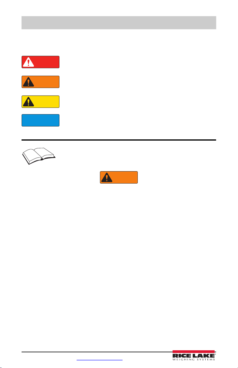
Safety Signal Definitions:
Indicates an imminently hazardous situation that, if not avoided, will
result in death or serious injury. Includes hazards that are exposed when
guards are removed.
Indicates a potentially hazardous situation that, if not avoided could
result in serious injury or death. Includes hazards that are exposed when
guards are removed.
Indicates a potentially hazardous situation that, if not avoided, could
result in minor or moderate injury.
Indicates information about procedures that, if not observed, could
result in damage to equipment or corruption to and loss of data.
General Safety
Do not operate or work on this equipment unless this manual has been
read and all instructions are understood. Contact any Rice Lake Weighing
Systems dealer for replacement manuals.
Failure to heed may result in serious injury or death.
DO NOT open the indicator, all procedures that require work inside the indicator enclosure
are to be performed by qualified service personnel only.
DO NOT allow minors (children) or inexperienced persons to operate this unit.
DO NOT operate without the enclosure completely assembled.
DO NOT use for purposes other than weight taking.
DO NOT place fingers into slots or possible pinch points.
DO NOT use this product if any of the components are cracked.
DO NOT exceed the rated specification of the unit.
DO NOT make alterations or modifications to the unit.
DO NOT remove or obscure warning labels.
DO NOT submerge.
Before opening the unit, ensure the power cord is disconnected from the outlet.
2 Visit our website www.RiceLake.com
Page 7

Introduction
1.2 Operating Modes
The 480 has two modes of operation:
Weigh Mode
The indicator displays gross or net weights as required, using the annunciators
described in Section 1.3.2 on page 5 to indicate scale status and the type of weight
value displayed.
User Menu Setup Mode
The user menu setup mode is used to access the Accumulator Functions, Audit Trail,
display the Tare, Unit ID, Time & Date, Setpoints, Serial Communications
parameters, Print Formats, and view the Firmware Version.
It is accessible by pressing the MENU key on the front panel.
1.3 Front Panel Display
Figure 1-1 shows the 480 LED annunciators, keypad and key functions.
The symbols shown by the keys (representing up, down, enter, left, right) describe the key
functions assigned in the operating modes. The keys are used to navigate through
menus, select digits within numeric values, and increment/decrement values.
Numeric Keypad – Enter numeric values.
PRELIMINARY
The up, down, enter, left and right arrows by the keys describe the
functions assigned in the operating modes.
Keys are also used to navigate through menus, select digits within
numeric values, and increment/decrement values.
Figure 1-1. 480 Front Panel, Showing LED Annunciators and Key Functions
© Rice Lake Weighing Systems ● All Rights Reserved 3
Page 8
480 Legend Series Digital Weight Indicator
POWER
MENU
ZERO
UNIT
PRINT
TARE
GROSS
NET
B/N
Note
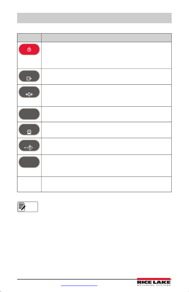
1.3.1 Key Functions
Key Function
Turns the unit on/off.
Note: If power mode is set to manual, the POWER button must be used to
turn the unit on and off. If power mode is set to auto, the unit will
automatically power on when it’s plugged in and the only way to turn it off is
to unplug power.
The MENU key is used to access the User Setup menu.
Sets the current gross weight to zero, provided the amount of weight to be
removed or added is within the specified zero range and the scale is not in motion.
The zero band is defaulted to 2% of full scale, but can be configured for up to 100%
of full scale.
Switches the weight display to an alternate unit.
In numeric entry mode used as a “clear” key.
Sends “on-demand” print format out the serial port, provided the conditions for
standstill are met. PRINT may be displayed while the unit prints.
Performs one of several predetermined Tare functions dependent on the mode of
operation s. To view a stored tare, see Section 1.5.6 on page 9.
Also acts as an “enter” key for numeric or parameter entry.
Toggles the display between gross and net. If a tare value has been entered or
acquired, the net value is the gross weight minus the tare.
Gross mode is shown by the Gross/Brutto annunciator; net mode is shown by the
Net annunciator.
During a numeric entry, sets the currently select digit to 0, then selects one digit to
the right.
See the 480 Legend Series Technical manual (PN 119201) for more information.
4 Visit our website www.RiceLake.com
Table 1-1. Key Functions
Page 9
Introduction
Note
1.3.2 Annunciator Functions
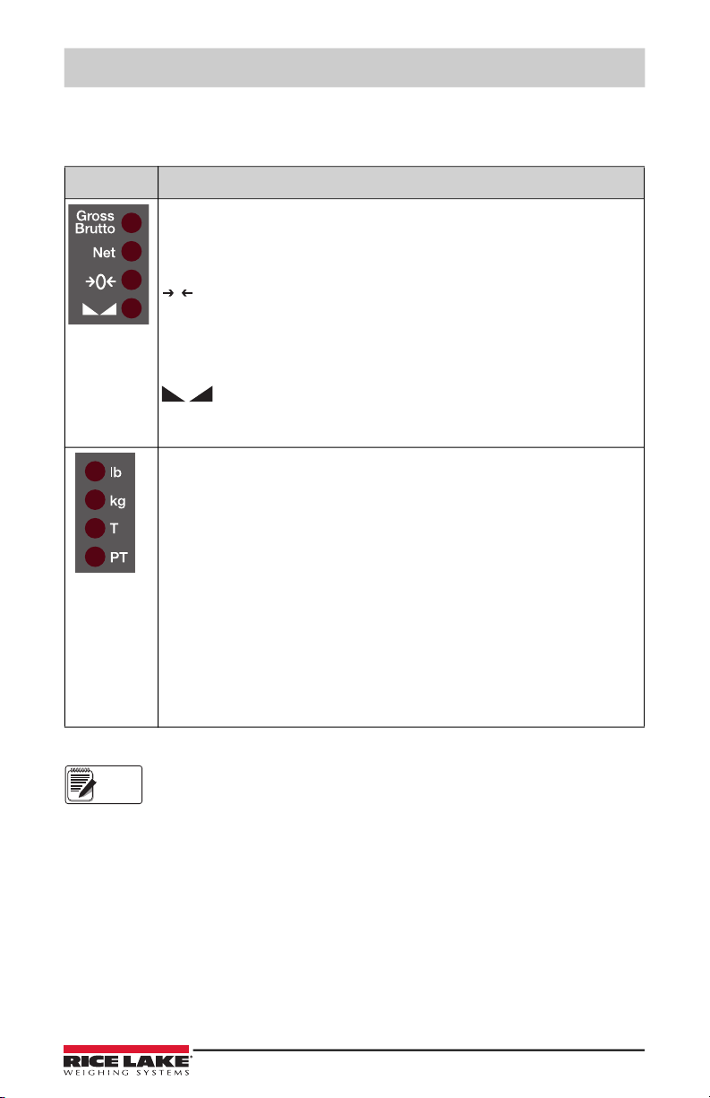
The 480 display uses a set of eight LED annunciators to provide additional information
about the value being displayed.
LED Description
Gross/Brutto LED
Gross weight display mode (or Brutto in OIML mode)
Net LED
Net weight display mode
Zero (Center of Zero) LED
0
The Center of Zero LED indicates that the current gross weight reading is within
+/- 0.25 display divisions of the acquired zero, or is within the center of zero band.
A display division is the resolution of the displayed weight value, or the smallest
incremental increase or decrease that can be displayed or printed.
Standstill LED
Scale is at standstill or within the specified motion band. Some operations,
including Zero, Tare and Printing, can only be done when the standstill LED is on.
lb/kg LED
Displays which unit of measure is being used.
lb and kg annunciators indicate the units associated with the displayed
value: lb = pounds, kg = kilograms.
The displayed units can also be set to short tons (tn), metric tons (t), ounces (oz),
grams (g), NONE (no units information displayed). The lb and kg LEDs function as
primary and secondary units annunciators. If neither primary nor secondary units
are lb or kg, the lb annunciator is lit for primary units and kg is lit for secondary
units.
T LED
Indicates that a push-button tare weight has been acquired and stored in memory.
PT LED
Indicates that a preset tare weight has been keyed in or entered and stored in
memory.
Table 1-2. LED Annunciators
See the 480 Legend Series Technical manual (PN 119201) for more information.
© Rice Lake Weighing Systems ● All Rights Reserved 5
Page 10
480 Legend Series Digital Weight Indicator
PRINT
MENU
UNIT
POWER
TARE
GROSS
NET
B/N
ZERO
Default value Value Value
When moving through values below the first menu level, press to return to the level above.
Value
1st Level
Parameter
2nd Level
Parameter
1st Level
Parameter
2nd Level
Parameter
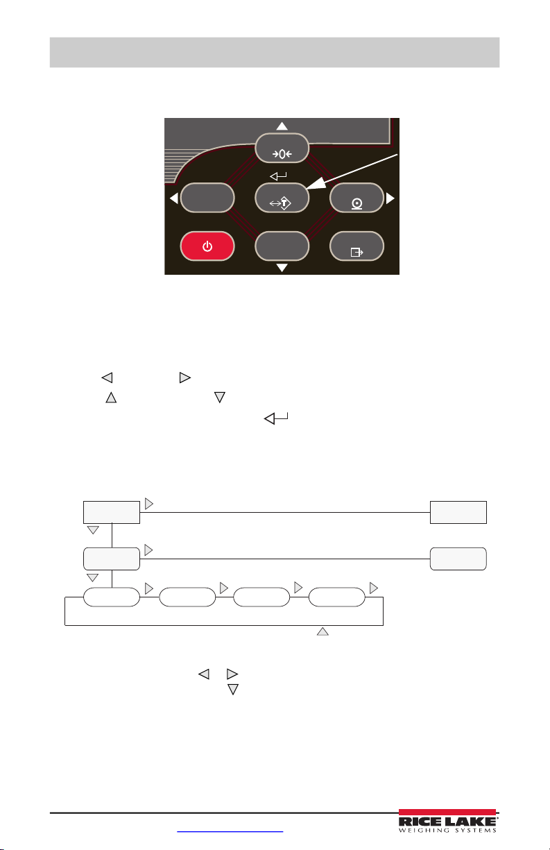
1.4 Front Panel Key Functions
Move UP/Increment Value
ENTER Value
Move LEFT/Previous
Power ON/OFF
Move RIGHT/Next
Move RIGHT/Next
Access User Setup
Move DOWN/Decrement Value
Figure 1-2. Front Panel Key Functions
Four front panel keys are used as directional keys to navigate through the menus (see
Figure 1-2).
UNIT ( ) and PRINT ( ) scroll left and right on the same menu level.
•
ZERO ( ) and GROSS/NET ( ) move up and down to different menu levels.
•
TARE key serves as an Enter key ( ) for selecting parameter values within the
• The
menus.
MENU key allows front panel access to user setup and configuration mode.
• The
1.4.1 Navigating Through Levels
Figure 1-3. Menu Navigation
To select a parameter, press or to scroll left or right until the desired menu group
appears on the display, then press to move down to the sub-menu or parameter you
want. When moving through the menu parameters, the present value appears first on the
display.
6 Visit our website www.RiceLake.com
Page 11

Introduction
0 0 0 0 0 0
When editing numeric values, press or to change the
digit selected. Press or to increment or decrement the
value of the selected digit. Press to save the value entered
and return to the level above.
Note
1.4.2 Edit Parameter Values
To change a parameter value, scroll left or right to view the values for that parameter.
When the desired value appears on the display, press
ENTER (TARE) to select the value
and move back up one level. To edit numerical values, use the navigation keys to select
the digit and to increment or decrement the value.
Figure 1-4. Editing Procedure for Numeric Values
1.4.3 Numeric Keypad - Editing Procedure (480Plus Only)
Figure 1-5. Numeric Keypad for the 480Plus
With the numeric keypad option, the method for editing numeric values relies on the
numbers which are embossed on the keypad in oppose to using the arrows.
1. When editing numeric values, insert the required value using the numeric keypad.
2. Press to save the value entered and return to the level above.
• Press to set the currently selected digit to 0.
• Press to enter a decimal point.
When editing fractional numeric values, the decimal point must be
positioned in accordance with the primary units formatting, otherwise the
keyed number may be rejected by the software.
© Rice Lake Weighing Systems ● All Rights Reserved 7
Page 12
480 Legend Series Digital Weight Indicator
Note
ZERO
UNIT
TARE
1.5 Indicator Operations
Basic 480 operations are summarized below.
See the 480 Legend Series Technical manual (PN 119201) for more
information.
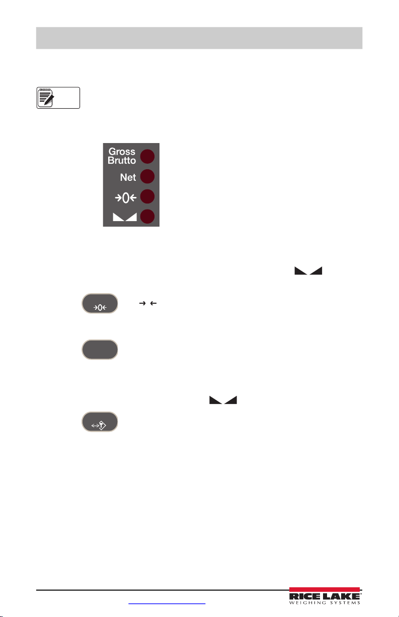
1.5.1 Status Lights While in Various Menus
Sub-menu levels are indicated by the LEDs as shown below.
First sub-menu level
Second sub-menu level
Third sub-menu level
Fourth sub-menu level
Figure 1-6. Status Lights
1.5.2 Zero Scale
1. In gross mode, remove all weight from the scale and wait for the LED to
light.
2. Press . The LED lights to indicate the scale is zeroed.
0
1.5.3 Toggle Units
1. Press to toggle between primary and secondary units. The current unit
LED will be lit.
1.5.4 Acquire Tare
1. Place container on scale and wait for the LED to light.
2. Press to acquire the tare weight of the container. Net weight is displayed
T LED lights to show the tare value was entered.
and the
See Section 3.2 on page 22 for Regulatory Mode Functions.
8 Visit our website www.RiceLake.com
Page 13
Introduction
TARE
TARE
0
MENU
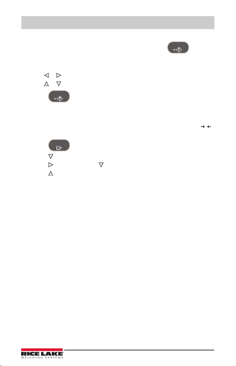
1.5.5 Preset Tare (Keyed Tare)
1. With the scale empty and display showing zero weight, press .
2. Display will show (000000); the focused digit will flash.
3. Edit the value using the following method; or with the 480PLUS, use the keypad.
• Press or to select the digit.
• Press or to increment or decrement the value.
4. Press when the value is correct. The display will change to the Net mode
PT LED lights to show the preset tare was entered.
and the
1.5.6 Display Tare
When a stored Tare value is displayed, the Gross and Net LEDs will be off and the
will be lit. To display a stored tare:
1. Press .
2. Press to AUDIT.
3. Press to
4. Press repeatedly to return to weighing mode.
If there is no tare in the system, the value displayed will be zero and the Gross and Net
LED will be turned off.
See Section 3.2 on page 22 for more information.
TARE and press .
© Rice Lake Weighing Systems ● All Rights Reserved 9
Page 14
480 Legend Series Digital Weight Indicator
PRINT
PRINT
GROSS
NET
B/N
MENU
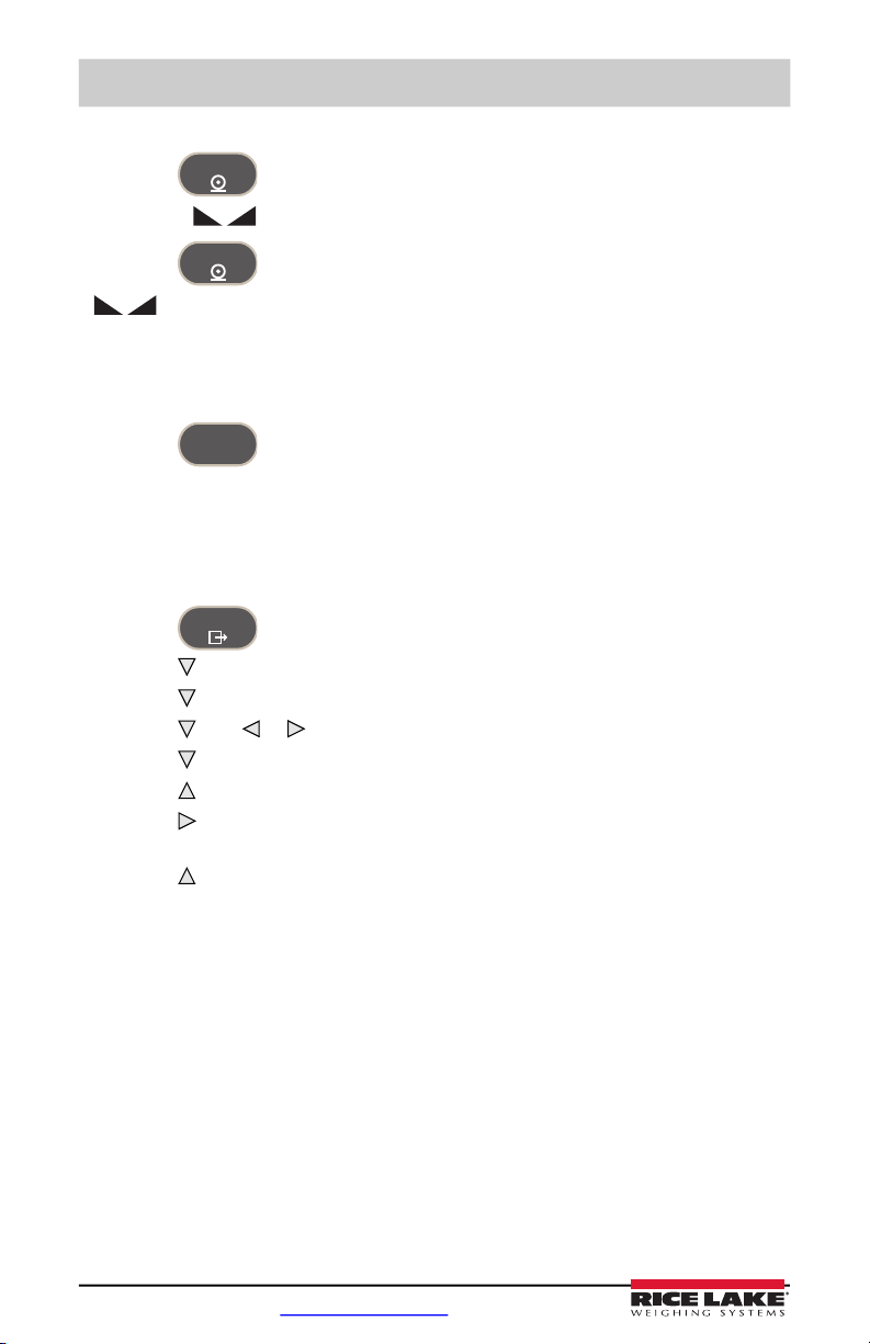
1.5.7 Print Ticket
1. Press to print either the Gross or Net format.
2. Wait for LED to light.
3. Press to send data to the serial port.
If LED is not lit and the
PRINT key is pressed, the print action will take place only
if the scale comes out of motion within 3 seconds. If the scale stays in motion for over 3
seconds, the PRINT key press is ignored.
1.5.8 Toggle Gross/Net Mode
1. Press to switch the display mode between gross and net. If a tare value
has been entered or acquired, the net value is the gross weight minus the tare.
Gross mode —
Gross/Brutto LED is lit.
Net mode — Net LED is lit.
1.5.9 View Audit Trail
1. Press .
2. Press to AUDIT.
3. Press . The audit trail CALIB is displayed.
4. Press then or to CNT, TIME or DATE.
5. Press to view selected parameter.
6. Press twice to return to CALIB.
7. Press to the audit trail CONFIG and repeat steps 5 and 6 to view configuration
number.
8. Press repeatedly to return to weighing mode.
10 Visit our website www.RiceLake.com
Page 15
Introduction
MENU
TARE
MENU
TARE
TARE
Note
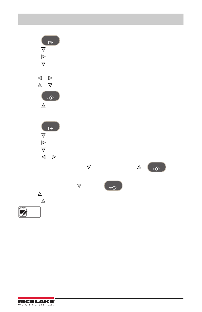
1.5.10 Enter New Unit ID
1. Press .
2. Press to AUDIT.
3. Press until display reads UNIT ID.
4. Press to view the current value.
5. Edit the value using the following method; or with the 480PLUS, use the keypad.
• Press or to select the digit.
• Press or to increment or decrement the value.
6. Press when the value is correct.
7. Press repeatedly to return to weighing mode.
1.5.11 Display Accumulator
1. Press .
2. Press to AUDIT.
3. Press until display reads ACCUM.
4. Press to display VIEW.
5. Press or to select desired parameter (VIEW, TIME, DATE, PRINT, CLR Y).
• For VIEW, TIME or DATE, press to view the value. Press or to return
to selected parameter.
• To PRINT or CLEAR, press , then press to print or clear the accumulator.
Press to return to selected parameter
6. Press repeatedly to return to weighing mode.
If the accumulated value exceeds 999999, display show “EE ACC”. The value
will still be correct and will print correctly up to 1,000,000,000.
© Rice Lake Weighing Systems ● All Rights Reserved 11
Page 16
480 Legend Series Digital Weight Indicator
MENU
TARE
Note
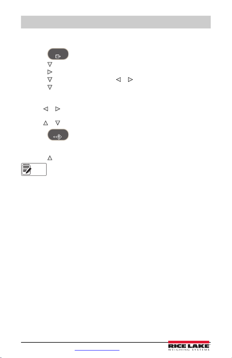
1.5.12 Display or Change Time and Date
To set the date and time:
1. Press .
2. Press to AUDIT.
3. Press until display reads TIMDAT (TIME/DATE).
4. Press and select Time or Date with or .
5. Press to view the current setting.
6. To edit the value of the time, in 24 hour or 12 hour format (hh.mm.ss), use the
following method.
• Press or to select hours, minutes, or seconds – the selected value will be
flashing
• Press or to increment or decrement the value.
7. Press when the value is correct.
Use the same procedure to enter the date in the same format configured for the
indicator.
8. Press repeatedly to return to weighing mode.
The time and date are backed up with an internal battery. If the main power is
interrupted, time and date will not be lost.
When in 12 hour format, the PT LED indicates pm setting.
12 Visit our website www.RiceLake.com
Page 17
Introduction
MENU
TARE
TARE
MENU
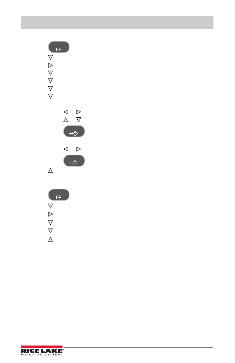
1.5.13 Display, Edit and Set Setpoint Value
1. Press .
2. Press to AUDIT.
3. Press until display reads
SETPNT.
4. Press and navigate across to desired setpoint number (1-8).
5. Press and navigate across to select User.
6. Press and navigate across to select Value or Enable.
7. Press to view and edit the value.
• To edit Value, use the following method; or with the 480PLUS, use the keypad.
• Press or to select the digit.
• Press or to increment or decrement the value.
• Press when the value is correct.
• To edit ENABLE:
• Press or to select ON/OFF.
• Press when the value is correct.
8. Press repeatedly to return to weighing mode.
1.5.14 View Firmware Version
1. Press .
2. Press . AUDIT is displayed.
3. Press until display reads VERS.
4. Press . FIRMW is displayed.
5. Press to view version.
6. Press repeatedly to return to weighing mode.
© Rice Lake Weighing Systems ● All Rights Reserved 13
Page 18
480 Legend Series Digital Weight Indicator
TARE
IMPORTANT
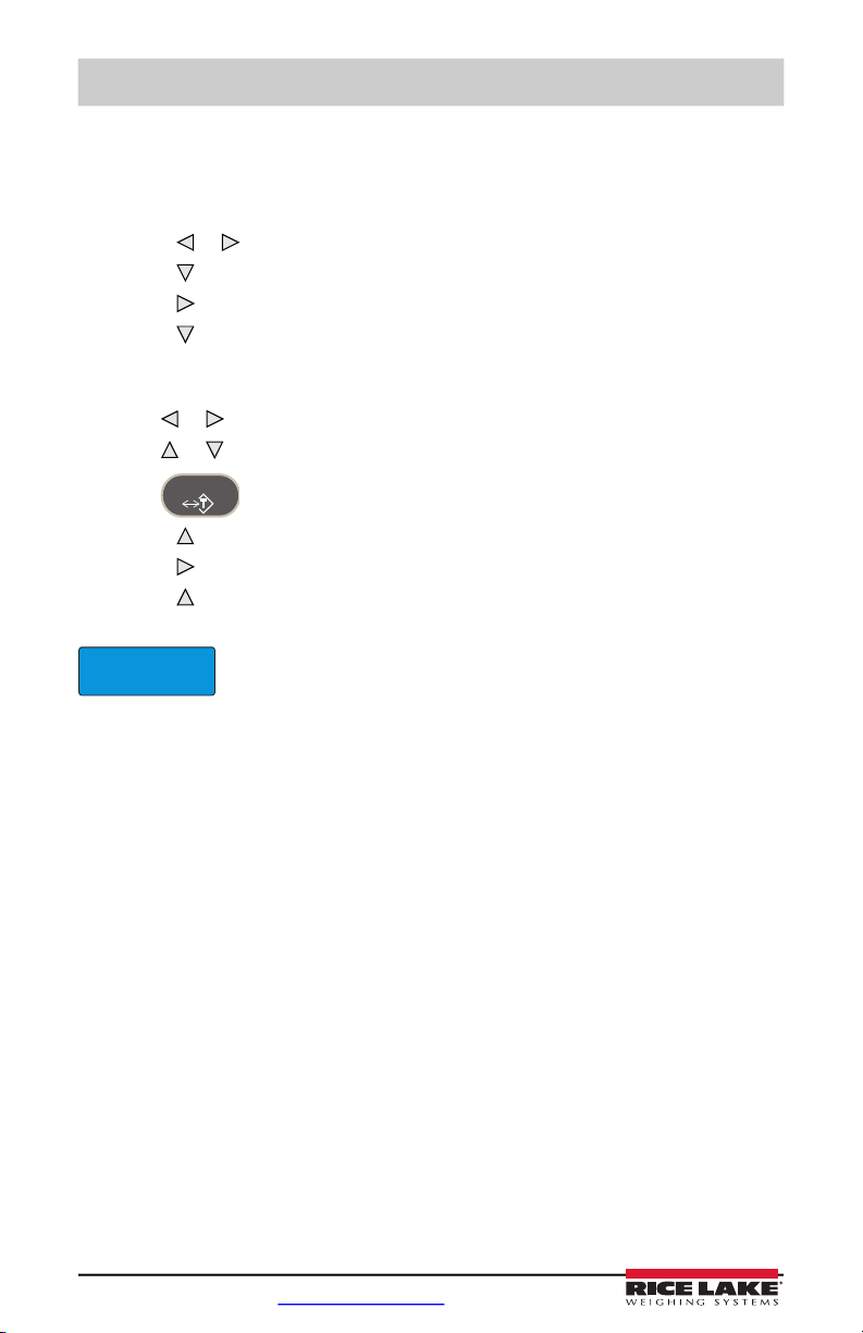
1.5.15 Enter User Password
1. Remove the setup switch access screw from the back of the enclosure.
2. Insert a non-conductive tool into the access hole and press the configuration switch.
Indicator display changes to show
3. Press or until PASWRD is displayed.
4. Press . CNFG is displayed.
5. Press to USER.
6. Press . 000000 is displayed.
7. To edit the password, use the following method; or with the 480PLUS, use the
keypad.
• Press or to select the digit.
• Press or to increment or decrement the value.
• Press when the value is correct.
8. Press to return to PASWRD.
9. Press to CONFIG.
10. Press to return to weighing mode.
When entering a user function, the operator will now be required to enter the password.
Enter 999999 to reset password, this will also reset the configuration
back to default values.
CONFIG.
14 Visit our website www.RiceLake.com
Page 19
2.0 User Menus
SETPNT
PFRMAT
MISC
TARE
0
AUDIT
CALIB
CNT
TIME
DATE
CONFIG
CNT
TIME
DATE
UNITID
000000
TIMDAT
TIME
DATE
ACCUM
TIME
DATE
VIEW
PRINT
CLR Y
MENU CONFIG FORMAT CALIBR PROGRM DIG IN ALGOUT PASWRD USBMEM TEST
VERS
SERIAL
ETHNET USB
TIMDAT
ACCUM
SERIALSETPNT
ETHNET
......
BATCHG SETPT1-8
USER
000000
PREACT
SUPVSR
CONFIG FORMAT CALIBR PROGRM DIG IN ALGOUT PASWRD USBMEMMENU TEST
AUTO
OFF
MANUAL
000000
VALUE
OFF
ON
ENABLE
OFF
ON
PUSHAC
OFF
ON
PUSHPR
OFF
ON
WAITSS
HIGHER
LOWER
TRIPKIND
OFF
GROSS
NET
-GROSS
-NET
DELAY
OFF
ON
PUSHTR
000000
HYSTER
OFF
ON
BATSEQ
NONE
1-8
DIGOUT
User Menus
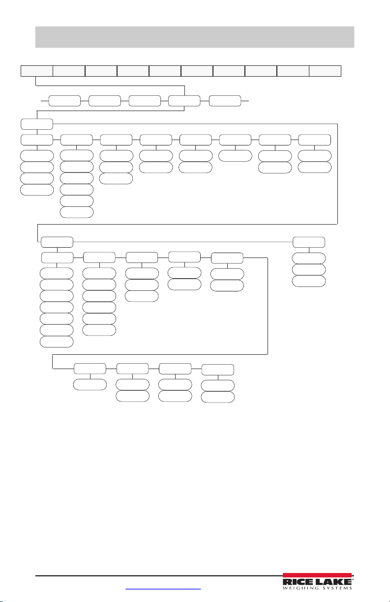
See
Figure 2-2
See
Figure 2-3
on page 16
See
Figure 2-4
on page 17
See
Figure 2-5
on page 18
See
Figure 2-6
on page 18
See
Figure 2-7
on page 19
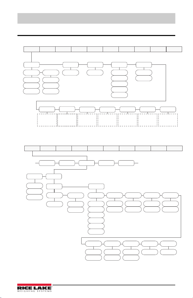
Figure 2-1. Menu Key User Menu
Figure 2-2. Setpoint Setup Menu
© Rice Lake Weighing Systems ● All Rights Reserved 15
See
Figure 2-8
on page 19
Page 20
480 Legend Series Digital Weight Indicator
COM-1
TIMDAT
ACCUM
SERIALSETPNT
PFRMAT
......
COM-2
STREAM
TRIGER
DEMAND
PRN
NONE
COMAND
BAUD
LOCAL
REMOTE
NONE
STRUR
STRLFT
STRIND
ECHO
OFF
ON
SBITS
1 STOP
2 STOP
TERMIN
CR
CR-LF
EOLDLY
000
BITS
7ODD
7EVEN
8NONE
PRNMSG
OFF
ON
BAUD
4800
2400
1200
19200
38400
9600
BITS
7ODD
7EVEN
8NONE
SBITS
1 STOP
2 STOP
TERMIN
CR
CR-LF
EOLDLY
000
ECHO
OFF
ON
PRNMSG
OFF
ON
TRIGER
STR2
STR3
STR4
NONE
PRN
STR1
STR5
4800
2400
1200
19200
38400
9600
MENU CONFIG FORMAT CALIBR PROGRM DIG IN ALGOUT PASWRD USBMEM TEST
16 Visit our website www.RiceLake.com
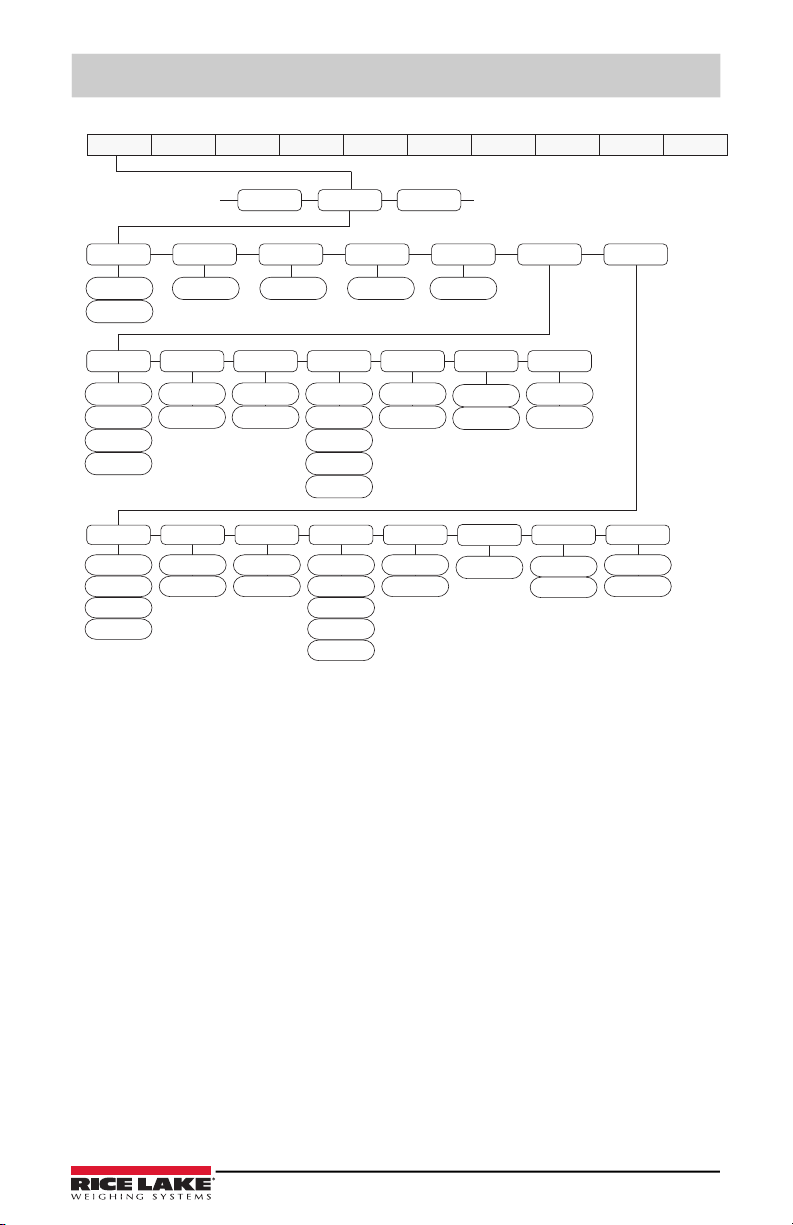
Figure 2-3. Serial Menu
Page 21
User Menus
0 - 65535
0 STR - 1
STR - 2
STR - 5
STR - 4
STR - 3
SERIAL
ETHNET
USB
...
...
IPADRS NETMSK DFTGWY MAC SERVER CLIENT
0.0.0.0
ON
OFF
0.0.0.0 0.0.0.0
00.00.00.00.00.00
DHCP
STRIND
STRLFT
COMAND
DEMAND
TRIGER TIMOUT
TERMIN SFMT
PORT EOLDLY ECHO
CR
CR/LF
0
0 - 255
1 - 65535
10001
ON
OFF
0 - 65535
0 STR - 1
STR - 2
STR - 5
STR - 4
STR - 3
STRIND
STRLFT
COMAND
DEMAND
TRIGER
TERMIN
CR
CR/LF
EOLDLY
0
0 - 255
RMPORT
1 - 65535
1
ECHO
ON
OFF
TIMOUT SFMT
RMOTIP
0.0.0.0
MENU CONFIG FORMAT CALIBR PROGRM DIG IN ALGOUT PASWRD USBMEM TEST
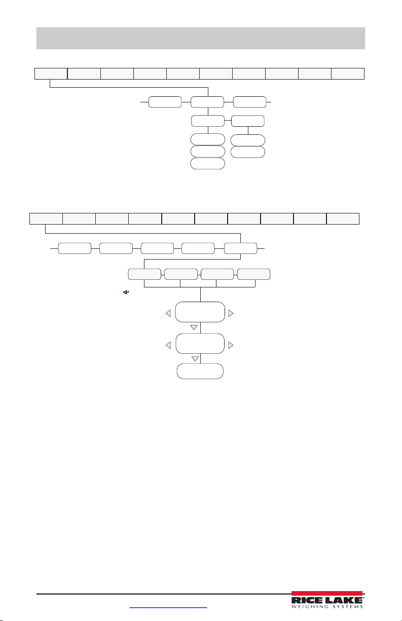
Figure 2-4. Ethernet Menu Layout
© Rice Lake Weighing Systems ● All Rights Reserved 17
Page 22
480 Legend Series Digital Weight Indicator
ETHNET USB
PFRMAT
...
...
TRIGER
DEVICE
PRINTR
HOSTPC
DRIVE
DEMAND
COMAND
MENU CONFIG FORMAT CALIBR PROGRM DIG IN ALGOUT PASWRD USBMEM TEST
TIMDAT
ACCUM
SERIALSETPNT
PFRMAT
......
Display rst 6
characters of format
Display and edit
active character and
ASCII value
Delete active
character
Scroll right in format string
Scroll left in format string
Increment ASCII value of active character
Decrement ASCII value of active character
Press to insert a space
before the active character
GFMT
NFMT
ACCFMT
SPFMT
MENU CONFIG FORMAT CALIBR PROGRM DIG IN ALGOUT PASWRD USBMEM TEST
Figure 2-5. USB Menu Layout
Figure 2-6. Print Format Menu
18 Visit our website www.RiceLake.com
Page 23
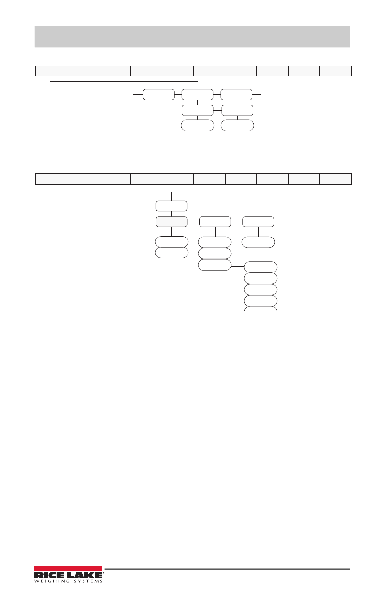
Figure 2-7. Version User Menu
VERSPFRMAT
MISC
......
FIRMW
LR
Legally
Relevant
VERSION VERSION
MENU CONFIG FORMAT CALIBR PROGRM DIG IN ALGOUT PASWRD USBMEM TEST
MISC
POWER
BKLGHT BAT
OFF
ON
AUTO
10 SEC
30 SEC
1 MIN
5 MIN
BAT LEVEL
AUTO
MANUAL
MENU CONFIG FORMAT CALIBR PROGRM DIG IN ALGOUT PASWRD USBMEM TEST
Figure 2-8. Misc. Menu
User Menus
© Rice Lake Weighing Systems ● All Rights Reserved 19
Page 24
480 Legend Series Digital Weight Indicator
3.0 Appendix
3.1 Error Messages
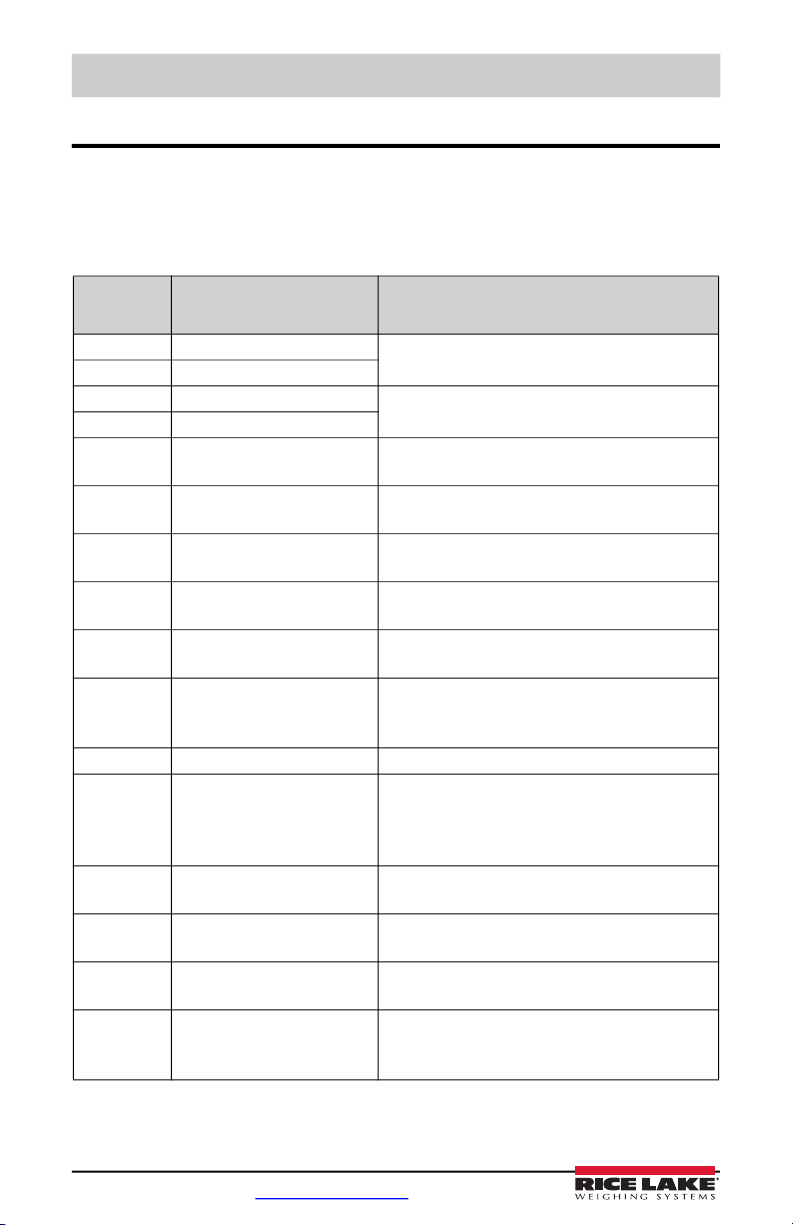
The 480 provides a number of front panel error messages to assist in problem diagnosis.
Table 3-1 lists these messages and their meanings.
Error
Message Description Solution
E A/D A/D physical error Call Rice Lake Weighing Systems (Rice Lake
EEEROM EEPROM physical error
EVIREE Virgin EEPROM Use TEST menu to perform DEFLT (restore
EPCKSM Parameter checksum error
EACKSM A/D calibration checksum
error
EFCKSM Printer format checksum error Call Rice Lake Weighing Systems Service at
ELCKSM Load cell calibration
checksum error
EIDATA Internal RAM checksum error Call Rice Lake Weighing Systems Service at
E REF A/D reference error A/D converter requires recalibration.
ERROR Internal program error Check configuration.
OVERFL Overflow error Weight value too large to be displayed.
- - - - - -
- - - - - -
- - - - - -
- - - - - RNGERR GRADS > 100,000
EEPERR EEPROM error Call Rice Lake Weighing Systems for service at
HINOFF? High offset Zero load at powerup is more than initial zero
Gross > overload limit Gross value exceeds overload limit. Check
Gross < 20d behind zero Gross value is more than 20 divisions behind zero.
WVAL > 100,000
Weighing Systems) Service at 800-472-6703.
defaults) procedure, then recalibrate load cells.
A/D converter requires recalibration.
Call Rice Lake Weighing Systems Service.
800-472-6703.
Recalibrate load cells.
800-472-6703.
Call Rice Lake Weighing Systems Service.
Call Rice Lake Weighing Systems Service if unable
to clear error by cycling power or if error recurs.
configuration or signal input level. Overload can be
caused by input signal > 45 mV or common mode
voltage > 950 mV.
Only shows up in Config mode.
800-472-6703.
range (INIZR) setting of calibration zero – remove
the extra load.
Table 3-1. 480 Error Messages
20 Visit our website www.RiceLake.com
Page 25
Appendix
Note
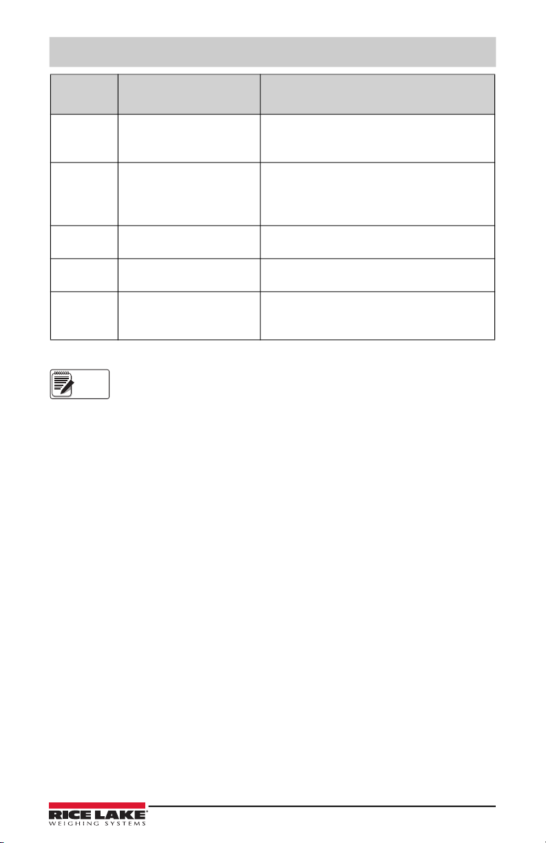
Error
Message Description Solution
LINOFF Low offset Zero load at power up is less than initial zero range
(INIZR) setting of calibration zero – add the
missing load.
NOBATT No battery The RTC lost time/date tracking at previous power
off state due to low battery or no battery condition.
The printer, accumulator and AUDUT functions will
fail to get time and date.
EUCKSM Configuration checksum The checksum value of configuration has changed
from that stored in memory.
OIMLER OIML parameter error Parameter set incorrectly for use in the OIML
mode. Example: Primary units set for lb or oz.
EE-ACC Accumulator error Error with the accumulator such as attempting to
display an accumulated value greater than six
digits.
Table 3-1. 480 Error Messages
Shorting the excitation voltage shuts the excitation voltage off. The only way
to restore excitation voltage is to cycle power.
© Rice Lake Weighing Systems ● All Rights Reserved 21
Page 26
480 Legend Series Digital Weight Indicator
Note
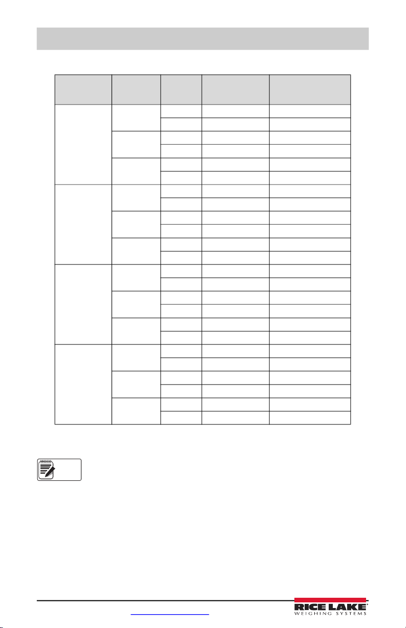
3.2 Regulatory Mode Functions
Regulatory
Parameter
NTEP Zero No “000000” Zero
Canada Zero No “000000” Zero
OIML Zero No “000000” Zero
None Zero No “000000” Zero
Weight On
Scale
Negative No No action Zero
Positive No Tare Zero
Negative No No action Zero
Positive No Tare Zero
Negative No No action Zero
Positive No “000000” Zero
Negative No No action Zero
Positive No Tare Zero
Tare In
System
Yes Clear tare Zero
Yes Clear tare Zero
Yes Tare Zero
Yes Clear tare Clear tare
Yes Clear tare Clear tare
Yes No action Clear tare
Yes Clear tare Zero & Clear tare
Yes Clear tare Zero & Clear tare
Yes Tare Zero & Clear Tare
Yes Clear tare Clear tare
Yes Clear tare Clear tare
Yes Clear tare Clear tare
Front Panel Key
Tare
Front Panel Key
Zero
Table 3-2. TARE and ZERO Key Functions for REGULAT Parameter Settings
At zero weight push-button tare will prompt for keyed tare when tare function
is set to keyed or both.
22 Visit our website www.RiceLake.com
Page 27
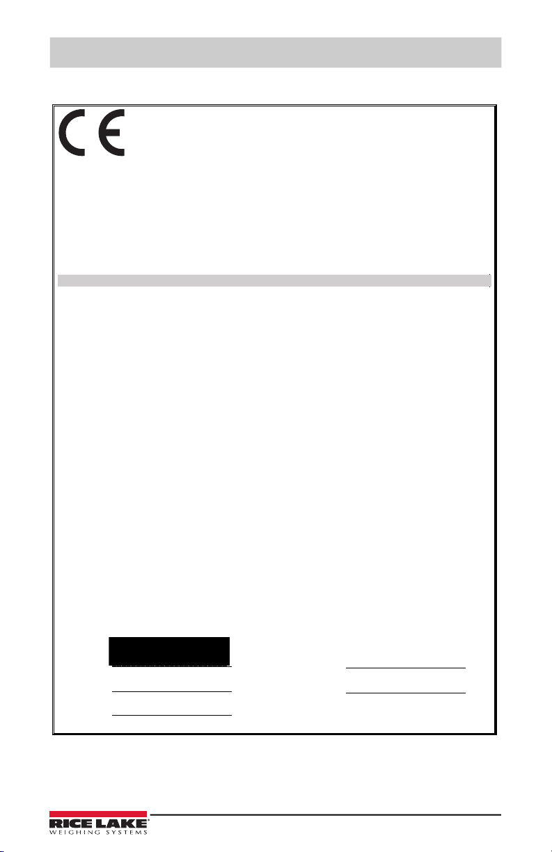
3.3 Compliance
5LFH/DNH:HLJKLQJ6\VWHPV
:HVW&ROHPDQ6WUHHW
5LFH/DNH:LVFRQVLQ
8QLWHG6WDWHVRI$PHULFD
6LJQDWXUH __________________________
3ODFH
7\SH1DPH 'DWH
7LWOH
5LFKDUG6KLSPDQ
4XDOLW\0DQDJHU
(8DECLARATIONOF
CONFORMITY
("#+,.$-#0#(1
#1/ 1(11 #&1
(8'LUHFWLYH &HUWLILFDWHV
6WDQGDUGV8VHG1RWLILHG%RG\,QYROYHPHQW
__________________________
__________________________
__________________________
5LFH/DNH:,86$
__________________________
7\SH7\S7\SH
(QJOLVK :H GHFODUHXQGHU RXU VROHUHVSRQVLELOLW\ WKDW WKH SURGXFWV WR ZKLFKWKLV GHFODUDWLRQ UHIHUVWR LV LQ FRQIRUPLW\ ZLWKWKH IROORZLQJ
VWDQGDUGV RURWKHUUHJXODWLRQV GRFXPHQWV
'HXWVFK :LUHUNOlUHQ XQWHUXQVHUHU DOOHLQLJHQ 9HUDQWZRUWXQJ GDVV GLH 3URGXNWH DXI GLHVLFK GLHVH (UNOlUXQJ EH]LHKW GHQIROJHQGHQ 1RUPHQ
XQG 5HJXOLHUXQJVEHVWLPPXQJHQ HQWVSUHFKHQ
)UDQFDLV 1RXVGpFODURQVVRXVQRWUHUHVSRQVDELOLWpTXHOHVSURGXLWVDX[TXHOVVHUDSSRUWHODSUpVHQWHGpFODUWLRQVRQWFRQIRUPHVjODDX[QRUPHV
VXLYDQWHRXDXDX[GRFXPHQWVQRUPDWLIVVXLYDQWV
480 and 482 indicator
Appendix
2014/30/EU EMC
2014/35/EU LVD
2011/65/EU RoHS
-
-
-
EN 55022:2010, EN 61000-3-2:2006+A1(09)+A2(09), EN 61000-3-3:2008, EN
55024:2010
EN 60950-1:2006+A11:2009+A1:2010+A12:2011+A2:2013
EN 50581:2012
© Rice Lake Weighing Systems ● All Rights Reserved 23
May 3, 2019
Page 28

480 Legend Series Digital Weight Indicator
3.4 Specifications
Model Numbers
United States 480-2A/480Plus-2A (NEMA Type 5-15)
International 480-2A/480Plus-2A (CEE 7/7)
Power – AC
Line Voltages 115 to 230 VAC
Frequency 50 or 60 Hz
Power Consumption 70 mA @ 115 VAC (8W)
35 mA @ 230 VAC (8W)
Fusing 2.5 A 5 x 20 mm fuse
Analog Specifications
Full Scale Input Signal Up to 35 mV
Excitation Voltage 5 ± 0.1VDC
Sense Amplifier Differential amplifier with
4- and 6-wire sensing
Analog Signal
Input Range Up to 7 mV/V
Analog Signal
Sensitivity 0.1 V/graduation minimum
0.5 V/grad recommended
Local Resistance 35-1140
Noise (ref to input) 0.5 V p-p
Internal Resolution 523,376 counts
Display Resolution 100,000 dd
Measurement Rate 37 measurements/sec
Input Sensitivity 38 nV per internal count
System Linearity Within 0.01% of full scale
Zero Stability 13 nV/°C
Span Stability 13 ppm/°C
Calibration Method Software, constants stored in EEPROM
Common Mode
Voltage AGND + 250mV V min
Excitation - 250 mV V max
Rejection 120 dB minimum @ 50 or 60 Hz
Normal Mode
Rejection 100 dB minimum @ 50 or 60 Hz
Input Overload -0.3 V to Excitation +0.3 V
RFI Protection Signal, excitation, and sense lines protected by capacitor bypass and
ESD suppressors
24 Visit our website www.RiceLake.com
Page 29

Appendix
Analog Output (Optional)
Type Fully isolated, voltage or current output,16-bit resolution.
Voltage output 0 –10 VDC
Voltage load resistance 1K minimum
Current output 0–20 mA or 4–20 mA
Current loop resistance 1200 maximum
Digital Specifications
Microprocessor ARM Cortex M3 STM32F103ZET6
Digital Filters Adaptive Filter and Rolling Averaging Filter; software selectable
Digital I/O (Optional)
Type Fully isolated
Digital Inputs 2 or 4 inputs, Opto isolated, 5 to 24 VDC input, active high
Digital Outputs 4 or 8 dry-contact relays
Up to 30VDC at 2A current
Serial Communications
Port 1 Full duplex RS-232
Port 2 Full duplex RS232, or output only Active 20mA current loop.
Both Ports 1200 to 38400 bps; 7 or 8 data bits; even, odd, or no parity; 1 or 2 stop
bits
Operator Interface
Display 6-digit LED display. 7-segment, 0.8 in (20 mm) digits
LED annunciators Gross, net, center of zero, standstill, lb/primary units, kg/secondary
Keypad 7-key flat membrane panel
units, T, PT
Environmental
Operating Temperature –10 to +40°C (legal);
–10 to +50°C (industrial)
Storage Temperature –25 to +70°C
Humidity 0–95% relative humidity
Enclosure
Enclosure Dimensions 9.5 in x 6 in x 2.75 in
24 cm x 15 cm x 7 cm
Weight 6 lb
Rating/Material 4X
© Rice Lake Weighing Systems ● All Rights Reserved 25
Page 30

480 Legend Series Digital Weight Indicator
Certifications and Approvals
NTEP
CoC Number 12-123
Accuracy Class III/IIIL n
max
: 10 000
OIML R76/2006-NL1-15.24
European Test Certificate TC8322
Accuracy Class III n
max
: 10 000
Measurement Canada
Approval AM-5892
Accuracy Class III/IIIHD n
max
: 10 000
UL
File Nubmer: 151461
FCC
The 480 complies with Part 15 of the FCC Rules. Operation is subject to the
following conditions:
•This device may not cause harmful interference.
•This device must accept any interference received, including interference that
may cause undesired operation.
Warranty
2-year limited warranty
•
26 Visit our website www.RiceLake.com
Page 31

Page 32

230 W. Coleman St. • Rice Lake, WI 54868 • USA
U.S. 800-472-6703 • Canada/Mexico 800-321-6703 • International 715-234-9171 • Europe +31 (0)26 472 1319
Rice Lake Weighing Systems is an ISO 9001 registered company.
© Rice Lake Weighing Systems Specifications subject to change without notice.
www.ricelake.com
PN 163374 Rev DOctober 3, 2019
 Loading...