

Page 1
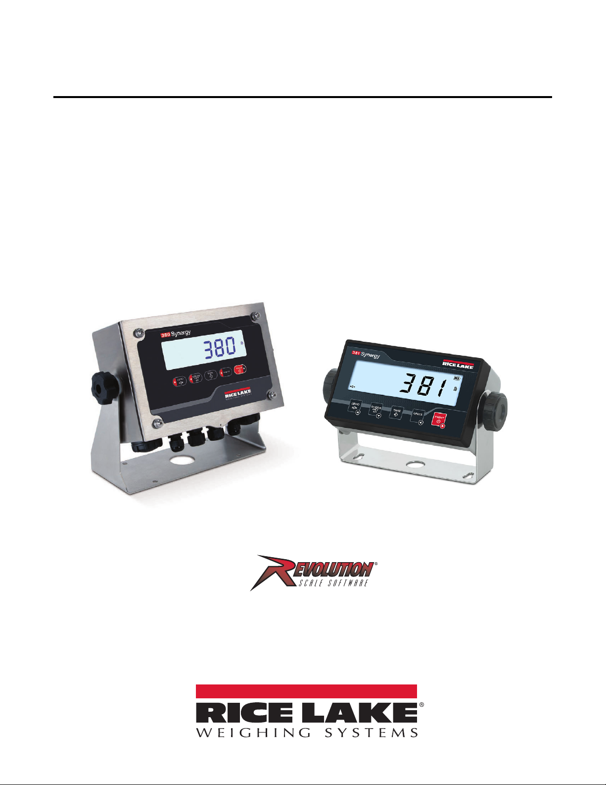
Synergy Series
380 and 381 Digital Weight Indicators
Technical Manual
380 Synergy Series Digital Weight Indicator 381 Synergy Series Digital Weight Indicator
August 16, 2023
PN 201481 Rev G
Page 2

© Rice Lake Weighing Systems. All rights reserved.
Rice Lake Weighing Systems
®
is a registered trademark of
Rice Lake Weighing Systems.
All other brand or product names within this publication are trademarks or
registered trademarks of their respective companies.
All information contained within this publication is, to the best of our knowledge, complete and
accurate at the time of publication. Rice Lake Weighing Systems reserves the right to make
changes to the technology, features, specifications and design of the equipment without notice.
The most current version of this publication, software, firmware and all other product
updates can be found on our website:
www.ricelake.com
Page 3
Technical training seminars are available through Rice Lake Weighing Systems.
Course descriptions and dates can be viewed at www.ricelake.com/training
or obtained by calling 715-234-9171 and asking for the training department.
Revision History
This section tracks and describes manual revisions for awareness of major updates.
Revision Date Description
D August 10, 2022 Revision history established; clarified configuration section and general formatting updates.
E November 3, 2022 Added cord grip diameter ranges.
F April 19, 2023 Added the 381 indicators to the manual.
G August 16, 2023 Added clarifying note about startup
Table i. Revision Letter History
Revision History
© Rice Lake Weighing Systems ● All Rights Reserved 3
Page 4
380/381 Synergy Indicator
Rice Lake continually offers web-based video training on a growing selection
of product-related topics at no cost. Visit www.ricelake.com/webinars
Contents
1.0 Introduction . . . . . . . . . . . . . . . . . . . . . . . . . . . . . . . . . . . . . . . . . . . . . . . . . . . . . . . . . . . . . . . . . . . . . . . . . . . . 7
1.1 Safety . . . . . . . . . . . . . . . . . . . . . . . . . . . . . . . . . . . . . . . . . . . . . . . . . . . . . . . . . . . . . . . . . . . . . . . . . . . . . . . . . . . . . . . . . . . . . 7
1.2 Options . . . . . . . . . . . . . . . . . . . . . . . . . . . . . . . . . . . . . . . . . . . . . . . . . . . . . . . . . . . . . . . . . . . . . . . . . . . . . . . . . . . . . . . . . . . . 8
1.3 Operating Modes. . . . . . . . . . . . . . . . . . . . . . . . . . . . . . . . . . . . . . . . . . . . . . . . . . . . . . . . . . . . . . . . . . . . . . . . . . . . . . . . . . . . . 8
1.4 FCC Compliance. . . . . . . . . . . . . . . . . . . . . . . . . . . . . . . . . . . . . . . . . . . . . . . . . . . . . . . . . . . . . . . . . . . . . . . . . . . . . . . . . . . . . 8
2.0 Installation . . . . . . . . . . . . . . . . . . . . . . . . . . . . . . . . . . . . . . . . . . . . . . . . . . . . . . . . . . . . . . . . . . . . . . . . . . . . . 9
2.1 Unpacking . . . . . . . . . . . . . . . . . . . . . . . . . . . . . . . . . . . . . . . . . . . . . . . . . . . . . . . . . . . . . . . . . . . . . . . . . . . . . . . . . . . . . . . . . . 9
2.2 380 Product Dimensions . . . . . . . . . . . . . . . . . . . . . . . . . . . . . . . . . . . . . . . . . . . . . . . . . . . . . . . . . . . . . . . . . . . . . . . . . . . . . . . 9
2.3 381 Product Dimensions . . . . . . . . . . . . . . . . . . . . . . . . . . . . . . . . . . . . . . . . . . . . . . . . . . . . . . . . . . . . . . . . . . . . . . . . . . . . . . 10
2.4 Mounting Instructions . . . . . . . . . . . . . . . . . . . . . . . . . . . . . . . . . . . . . . . . . . . . . . . . . . . . . . . . . . . . . . . . . . . . . . . . . . . . . . . . 10
2.5 Open Enclosure . . . . . . . . . . . . . . . . . . . . . . . . . . . . . . . . . . . . . . . . . . . . . . . . . . . . . . . . . . . . . . . . . . . . . . . . . . . . . . . . . . . . 11
2.5.1 380 Front Plate Removal . . . . . . . . . . . . . . . . . . . . . . . . . . . . . . . . . . . . . . . . . . . . . . . . . . . . . . . . . . . . . . . . . . . . . . 11
2.5.2 381 Back Plate Removal . . . . . . . . . . . . . . . . . . . . . . . . . . . . . . . . . . . . . . . . . . . . . . . . . . . . . . . . . . . . . . . . . . . . . . 12
2.6 Cord Grip Connections . . . . . . . . . . . . . . . . . . . . . . . . . . . . . . . . . . . . . . . . . . . . . . . . . . . . . . . . . . . . . . . . . . . . . . . . . . . . . . . 13
2.6.1 380 Cord Grip Connections (PN 202711) . . . . . . . . . . . . . . . . . . . . . . . . . . . . . . . . . . . . . . . . . . . . . . . . . . . . . . . . . 13
2.6.2 381-2D-AA Cord Grip Connections (PN 215695) . . . . . . . . . . . . . . . . . . . . . . . . . . . . . . . . . . . . . . . . . . . . . . . . . . . 14
2.6.3 381-2D-NiMH Cord Grip Connections (PN 185064) . . . . . . . . . . . . . . . . . . . . . . . . . . . . . . . . . . . . . . . . . . . . . . . . . 14
2.7 380 Cable Shield Grounding . . . . . . . . . . . . . . . . . . . . . . . . . . . . . . . . . . . . . . . . . . . . . . . . . . . . . . . . . . . . . . . . . . . . . . . . . . . 15
2.8 CPU Board Connections . . . . . . . . . . . . . . . . . . . . . . . . . . . . . . . . . . . . . . . . . . . . . . . . . . . . . . . . . . . . . . . . . . . . . . . . . . . . . . 16
2.8.1 Load Cell Cable . . . . . . . . . . . . . . . . . . . . . . . . . . . . . . . . . . . . . . . . . . . . . . . . . . . . . . . . . . . . . . . . . . . . . . . . . . . . . 16
2.8.2 380 RS-232 Serial Communications . . . . . . . . . . . . . . . . . . . . . . . . . . . . . . . . . . . . . . . . . . . . . . . . . . . . . . . . . . . . . 16
2.9 Power Connections . . . . . . . . . . . . . . . . . . . . . . . . . . . . . . . . . . . . . . . . . . . . . . . . . . . . . . . . . . . . . . . . . . . . . . . . . . . . . . . . . . 17
2.9.1 380-2D Power Connections . . . . . . . . . . . . . . . . . . . . . . . . . . . . . . . . . . . . . . . . . . . . . . . . . . . . . . . . . . . . . . . . . . . . 17
2.9.2 381-2D-AA Power Connections . . . . . . . . . . . . . . . . . . . . . . . . . . . . . . . . . . . . . . . . . . . . . . . . . . . . . . . . . . . . . . . . . 18
2.9.3 381-2D-NiMH Power Connections . . . . . . . . . . . . . . . . . . . . . . . . . . . . . . . . . . . . . . . . . . . . . . . . . . . . . . . . . . . . . . . 18
2.10 Reassembly . . . . . . . . . . . . . . . . . . . . . . . . . . . . . . . . . . . . . . . . . . . . . . . . . . . . . . . . . . . . . . . . . . . . . . . . . . . . . . . . . . . . . . . 19
2.10.1 380 Front Plate Reattachment . . . . . . . . . . . . . . . . . . . . . . . . . . . . . . . . . . . . . . . . . . . . . . . . . . . . . . . . . . . . . . . . . . 19
2.10.2 381 Reassembly . . . . . . . . . . . . . . . . . . . . . . . . . . . . . . . . . . . . . . . . . . . . . . . . . . . . . . . . . . . . . . . . . . . . . . . . . . . . 19
2.11 380 Parts Kit Components . . . . . . . . . . . . . . . . . . . . . . . . . . . . . . . . . . . . . . . . . . . . . . . . . . . . . . . . . . . . . . . . . . . . . . . . . . . . 20
2.12 Replacement Parts . . . . . . . . . . . . . . . . . . . . . . . . . . . . . . . . . . . . . . . . . . . . . . . . . . . . . . . . . . . . . . . . . . . . . . . . . . . . . . . . . . 21
3.0 Operation . . . . . . . . . . . . . . . . . . . . . . . . . . . . . . . . . . . . . . . . . . . . . . . . . . . . . . . . . . . . . . . . . . . . . . . . . . . . . 24
3.1 Front Panel . . . . . . . . . . . . . . . . . . . . . . . . . . . . . . . . . . . . . . . . . . . . . . . . . . . . . . . . . . . . . . . . . . . . . . . . . . . . . . . . . . . . . . . . 24
3.2 LCD Annunciators . . . . . . . . . . . . . . . . . . . . . . . . . . . . . . . . . . . . . . . . . . . . . . . . . . . . . . . . . . . . . . . . . . . . . . . . . . . . . . . . . . . 25
3.3 General Navigation . . . . . . . . . . . . . . . . . . . . . . . . . . . . . . . . . . . . . . . . . . . . . . . . . . . . . . . . . . . . . . . . . . . . . . . . . . . . . . . . . . 25
3.3.1 Numeric Value Entry . . . . . . . . . . . . . . . . . . . . . . . . . . . . . . . . . . . . . . . . . . . . . . . . . . . . . . . . . . . . . . . . . . . . . . . . . 26
3.3.2 Alphanumeric Entry . . . . . . . . . . . . . . . . . . . . . . . . . . . . . . . . . . . . . . . . . . . . . . . . . . . . . . . . . . . . . . . . . . . . . . . . . . 26
3.4 Weigh Mode Operation . . . . . . . . . . . . . . . . . . . . . . . . . . . . . . . . . . . . . . . . . . . . . . . . . . . . . . . . . . . . . . . . . . . . . . . . . . . . . . . 27
3.4.1 Zero Scale . . . . . . . . . . . . . . . . . . . . . . . . . . . . . . . . . . . . . . . . . . . . . . . . . . . . . . . . . . . . . . . . . . . . . . . . . . . . . . . . . 27
3.4.2 Print Ticket . . . . . . . . . . . . . . . . . . . . . . . . . . . . . . . . . . . . . . . . . . . . . . . . . . . . . . . . . . . . . . . . . . . . . . . . . . . . . . . . . 27
3.4.3 Toggle Units . . . . . . . . . . . . . . . . . . . . . . . . . . . . . . . . . . . . . . . . . . . . . . . . . . . . . . . . . . . . . . . . . . . . . . . . . . . . . . . . 27
3.4.4 Toggle Gross/Net Mode . . . . . . . . . . . . . . . . . . . . . . . . . . . . . . . . . . . . . . . . . . . . . . . . . . . . . . . . . . . . . . . . . . . . . . . 27
3.4.5 Acquire Tare. . . . . . . . . . . . . . . . . . . . . . . . . . . . . . . . . . . . . . . . . . . . . . . . . . . . . . . . . . . . . . . . . . . . . . . . . . . . . . . . 27
3.4.6 Remove Tare Value . . . . . . . . . . . . . . . . . . . . . . . . . . . . . . . . . . . . . . . . . . . . . . . . . . . . . . . . . . . . . . . . . . . . . . . . . . 27
3.4.7 Preset Tare (Keyed Tare) . . . . . . . . . . . . . . . . . . . . . . . . . . . . . . . . . . . . . . . . . . . . . . . . . . . . . . . . . . . . . . . . . . . . . 27
4 Visit our website www.RiceLake.com
Page 5

Contents
Technical training seminars are available through Rice Lake Weighing Systems.
Course descriptions and dates can be viewed at www.ricelake.com/training
or obtained by calling 715-234-9171 and asking for the training department.
3.5 User Mode Menu. . . . . . . . . . . . . . . . . . . . . . . . . . . . . . . . . . . . . . . . . . . . . . . . . . . . . . . . . . . . . . . . . . . . . . . . . . . . . . . . . . . . 28
3.5.1 Display a Stored Tare . . . . . . . . . . . . . . . . . . . . . . . . . . . . . . . . . . . . . . . . . . . . . . . . . . . . . . . . . . . . . . . . . . . . . . . . 28
3.5.2 Clear a Stored Tare . . . . . . . . . . . . . . . . . . . . . . . . . . . . . . . . . . . . . . . . . . . . . . . . . . . . . . . . . . . . . . . . . . . . . . . . . . 28
3.5.3 View Legally Relevant Version. . . . . . . . . . . . . . . . . . . . . . . . . . . . . . . . . . . . . . . . . . . . . . . . . . . . . . . . . . . . . . . . . . 28
3.5.4 Display Accumulator . . . . . . . . . . . . . . . . . . . . . . . . . . . . . . . . . . . . . . . . . . . . . . . . . . . . . . . . . . . . . . . . . . . . . . . . . 28
3.5.5 Print Accumulator. . . . . . . . . . . . . . . . . . . . . . . . . . . . . . . . . . . . . . . . . . . . . . . . . . . . . . . . . . . . . . . . . . . . . . . . . . . . 29
3.5.6 Clear Accumulator . . . . . . . . . . . . . . . . . . . . . . . . . . . . . . . . . . . . . . . . . . . . . . . . . . . . . . . . . . . . . . . . . . . . . . . . . . . 29
3.6 Reset (Default) Configuration . . . . . . . . . . . . . . . . . . . . . . . . . . . . . . . . . . . . . . . . . . . . . . . . . . . . . . . . . . . . . . . . . . . . . . . . . . 29
4.0 Configuration . . . . . . . . . . . . . . . . . . . . . . . . . . . . . . . . . . . . . . . . . . . . . . . . . . . . . . . . . . . . . . . . . . . . . . . . . . 30
4.1 Seal the Indicator . . . . . . . . . . . . . . . . . . . . . . . . . . . . . . . . . . . . . . . . . . . . . . . . . . . . . . . . . . . . . . . . . . . . . . . . . . . . . . . . . . . 30
4.1.1 Close the CAL Jumper . . . . . . . . . . . . . . . . . . . . . . . . . . . . . . . . . . . . . . . . . . . . . . . . . . . . . . . . . . . . . . . . . . . . . . . . 30
4.1.2 Seal the 380 . . . . . . . . . . . . . . . . . . . . . . . . . . . . . . . . . . . . . . . . . . . . . . . . . . . . . . . . . . . . . . . . . . . . . . . . . . . . . . . . 31
4.1.3 Seal the 381 . . . . . . . . . . . . . . . . . . . . . . . . . . . . . . . . . . . . . . . . . . . . . . . . . . . . . . . . . . . . . . . . . . . . . . . . . . . . . . . . 31
4.2 Main Menu . . . . . . . . . . . . . . . . . . . . . . . . . . . . . . . . . . . . . . . . . . . . . . . . . . . . . . . . . . . . . . . . . . . . . . . . . . . . . . . . . . . . . . . . 32
4.3 Setup Menu. . . . . . . . . . . . . . . . . . . . . . . . . . . . . . . . . . . . . . . . . . . . . . . . . . . . . . . . . . . . . . . . . . . . . . . . . . . . . . . . . . . . . . . . 32
4.3.1 Setup – Configuration Menu . . . . . . . . . . . . . . . . . . . . . . . . . . . . . . . . . . . . . . . . . . . . . . . . . . . . . . . . . . . . . . . . . . . 33
4.3.2 Setup – Format Menu . . . . . . . . . . . . . . . . . . . . . . . . . . . . . . . . . . . . . . . . . . . . . . . . . . . . . . . . . . . . . . . . . . . . . . . . 34
4.3.3 Setup – Calibration Menu. . . . . . . . . . . . . . . . . . . . . . . . . . . . . . . . . . . . . . . . . . . . . . . . . . . . . . . . . . . . . . . . . . . . . . 34
4.3.4 Setup – Communication Menu. . . . . . . . . . . . . . . . . . . . . . . . . . . . . . . . . . . . . . . . . . . . . . . . . . . . . . . . . . . . . . . . . . 35
4.3.5 Setup – Program Menu . . . . . . . . . . . . . . . . . . . . . . . . . . . . . . . . . . . . . . . . . . . . . . . . . . . . . . . . . . . . . . . . . . . . . . . 36
4.3.6 Setup – Print Format Menu . . . . . . . . . . . . . . . . . . . . . . . . . . . . . . . . . . . . . . . . . . . . . . . . . . . . . . . . . . . . . . . . . . . . 37
4.3.7 Setup – Stream Format Menu . . . . . . . . . . . . . . . . . . . . . . . . . . . . . . . . . . . . . . . . . . . . . . . . . . . . . . . . . . . . . . . . . . 38
4.4 Accumulator Menu . . . . . . . . . . . . . . . . . . . . . . . . . . . . . . . . . . . . . . . . . . . . . . . . . . . . . . . . . . . . . . . . . . . . . . . . . . . . . . . . . . 38
4.5 Tare Menu. . . . . . . . . . . . . . . . . . . . . . . . . . . . . . . . . . . . . . . . . . . . . . . . . . . . . . . . . . . . . . . . . . . . . . . . . . . . . . . . . . . . . . . . . 39
4.6 Audit Menu . . . . . . . . . . . . . . . . . . . . . . . . . . . . . . . . . . . . . . . . . . . . . . . . . . . . . . . . . . . . . . . . . . . . . . . . . . . . . . . . . . . . . . . . 39
5.0 Calibration . . . . . . . . . . . . . . . . . . . . . . . . . . . . . . . . . . . . . . . . . . . . . . . . . . . . . . . . . . . . . . . . . . . . . . . . . . . . 40
5.1 Front Panel Calibration . . . . . . . . . . . . . . . . . . . . . . . . . . . . . . . . . . . . . . . . . . . . . . . . . . . . . . . . . . . . . . . . . . . . . . . . . . . . . . . 40
5.1.1 Span Calibration. . . . . . . . . . . . . . . . . . . . . . . . . . . . . . . . . . . . . . . . . . . . . . . . . . . . . . . . . . . . . . . . . . . . . . . . . . . . . 40
5.1.2 Linear Calibration . . . . . . . . . . . . . . . . . . . . . . . . . . . . . . . . . . . . . . . . . . . . . . . . . . . . . . . . . . . . . . . . . . . . . . . . . . . . 41
5.2 Alternative Zero Calibrations. . . . . . . . . . . . . . . . . . . . . . . . . . . . . . . . . . . . . . . . . . . . . . . . . . . . . . . . . . . . . . . . . . . . . . . . . . . 41
5.2.1 Last Zero . . . . . . . . . . . . . . . . . . . . . . . . . . . . . . . . . . . . . . . . . . . . . . . . . . . . . . . . . . . . . . . . . . . . . . . . . . . . . . . . . . 41
5.2.2 Temporary Zero . . . . . . . . . . . . . . . . . . . . . . . . . . . . . . . . . . . . . . . . . . . . . . . . . . . . . . . . . . . . . . . . . . . . . . . . . . . . . 41
5.2.3 Rezero . . . . . . . . . . . . . . . . . . . . . . . . . . . . . . . . . . . . . . . . . . . . . . . . . . . . . . . . . . . . . . . . . . . . . . . . . . . . . . . . . . . . 41
5.3 EDP Command Calibration . . . . . . . . . . . . . . . . . . . . . . . . . . . . . . . . . . . . . . . . . . . . . . . . . . . . . . . . . . . . . . . . . . . . . . . . . . . . 42
6.0 Revolution . . . . . . . . . . . . . . . . . . . . . . . . . . . . . . . . . . . . . . . . . . . . . . . . . . . . . . . . . . . . . . . . . . . . . . . . . . . . 43
6.1 Connecting to the Indicator . . . . . . . . . . . . . . . . . . . . . . . . . . . . . . . . . . . . . . . . . . . . . . . . . . . . . . . . . . . . . . . . . . . . . . . . . . . . 43
6.2 Saving and Transferring Data . . . . . . . . . . . . . . . . . . . . . . . . . . . . . . . . . . . . . . . . . . . . . . . . . . . . . . . . . . . . . . . . . . . . . . . . . . 43
6.2.1 Saving Indicator Data to a Personal Computer . . . . . . . . . . . . . . . . . . . . . . . . . . . . . . . . . . . . . . . . . . . . . . . . . . . . . 43
6.2.2 Downloading Configuration Data from PC to Indicator . . . . . . . . . . . . . . . . . . . . . . . . . . . . . . . . . . . . . . . . . . . . . . . 43
7.0 EDP Commands. . . . . . . . . . . . . . . . . . . . . . . . . . . . . . . . . . . . . . . . . . . . . . . . . . . . . . . . . . . . . . . . . . . . . . . . 44
7.1 Key Press Commands . . . . . . . . . . . . . . . . . . . . . . . . . . . . . . . . . . . . . . . . . . . . . . . . . . . . . . . . . . . . . . . . . . . . . . . . . . . . . . . 44
7.2 Reporting Commands . . . . . . . . . . . . . . . . . . . . . . . . . . . . . . . . . . . . . . . . . . . . . . . . . . . . . . . . . . . . . . . . . . . . . . . . . . . . . . . . 45
7.3 Reset Configuration Command. . . . . . . . . . . . . . . . . . . . . . . . . . . . . . . . . . . . . . . . . . . . . . . . . . . . . . . . . . . . . . . . . . . . . . . . . 45
7.4 Parameter Setting Commands . . . . . . . . . . . . . . . . . . . . . . . . . . . . . . . . . . . . . . . . . . . . . . . . . . . . . . . . . . . . . . . . . . . . . . . . . 45
7.5 USB Setting Commands . . . . . . . . . . . . . . . . . . . . . . . . . . . . . . . . . . . . . . . . . . . . . . . . . . . . . . . . . . . . . . . . . . . . . . . . . . . . . . 46
7.6 EDP Setting Commands . . . . . . . . . . . . . . . . . . . . . . . . . . . . . . . . . . . . . . . . . . . . . . . . . . . . . . . . . . . . . . . . . . . . . . . . . . . . . 47
7.7 Stream Setting Commands . . . . . . . . . . . . . . . . . . . . . . . . . . . . . . . . . . . . . . . . . . . . . . . . . . . . . . . . . . . . . . . . . . . . . . . . . . . . 47
© Rice Lake Weighing Systems ● All Rights Reserved 5
Page 6

380/381 Synergy Indicator
Rice Lake continually offers web-based video training on a growing selection
of product-related topics at no cost. Visit www.ricelake.com/webinars
7.8 Feature Commands . . . . . . . . . . . . . . . . . . . . . . . . . . . . . . . . . . . . . . . . . . . . . . . . . . . . . . . . . . . . . . . . . . . . . . . . . . . . . . . . . 47
7.9 Print Format Commands . . . . . . . . . . . . . . . . . . . . . . . . . . . . . . . . . . . . . . . . . . . . . . . . . . . . . . . . . . . . . . . . . . . . . . . . . . . . . . 48
7.10 Weigh Mode Commands. . . . . . . . . . . . . . . . . . . . . . . . . . . . . . . . . . . . . . . . . . . . . . . . . . . . . . . . . . . . . . . . . . . . . . . . . . . . . . 48
8.0 Print Formatting. . . . . . . . . . . . . . . . . . . . . . . . . . . . . . . . . . . . . . . . . . . . . . . . . . . . . . . . . . . . . . . . . . . . . . . . 49
8.1 Print Formatting Tokens . . . . . . . . . . . . . . . . . . . . . . . . . . . . . . . . . . . . . . . . . . . . . . . . . . . . . . . . . . . . . . . . . . . . . . . . . . . . . . 49
8.2 Customizing Print Formats . . . . . . . . . . . . . . . . . . . . . . . . . . . . . . . . . . . . . . . . . . . . . . . . . . . . . . . . . . . . . . . . . . . . . . . . . . . . 50
8.3 Non-Human Readable Characters . . . . . . . . . . . . . . . . . . . . . . . . . . . . . . . . . . . . . . . . . . . . . . . . . . . . . . . . . . . . . . . . . . . . . . 50
9.0 Maintenance . . . . . . . . . . . . . . . . . . . . . . . . . . . . . . . . . . . . . . . . . . . . . . . . . . . . . . . . . . . . . . . . . . . . . . . . . . . 51
9.1 Maintenance Checkpoints. . . . . . . . . . . . . . . . . . . . . . . . . . . . . . . . . . . . . . . . . . . . . . . . . . . . . . . . . . . . . . . . . . . . . . . . . . . . . 51
9.2 Field Wiring . . . . . . . . . . . . . . . . . . . . . . . . . . . . . . . . . . . . . . . . . . . . . . . . . . . . . . . . . . . . . . . . . . . . . . . . . . . . . . . . . . . . . . . . 51
9.3 Troubleshooting . . . . . . . . . . . . . . . . . . . . . . . . . . . . . . . . . . . . . . . . . . . . . . . . . . . . . . . . . . . . . . . . . . . . . . . . . . . . . . . . . . . . 51
9.4 Board Replacement . . . . . . . . . . . . . . . . . . . . . . . . . . . . . . . . . . . . . . . . . . . . . . . . . . . . . . . . . . . . . . . . . . . . . . . . . . . . . . . . . 52
9.5 Updating Firmware . . . . . . . . . . . . . . . . . . . . . . . . . . . . . . . . . . . . . . . . . . . . . . . . . . . . . . . . . . . . . . . . . . . . . . . . . . . . . . . . . . 52
9.5.1 With Revolution . . . . . . . . . . . . . . . . . . . . . . . . . . . . . . . . . . . . . . . . . . . . . . . . . . . . . . . . . . . . . . . . . . . . . . . . . . . . . 52
9.5.2 Without Revolution . . . . . . . . . . . . . . . . . . . . . . . . . . . . . . . . . . . . . . . . . . . . . . . . . . . . . . . . . . . . . . . . . . . . . . . . . . . 52
10.0 Appendix . . . . . . . . . . . . . . . . . . . . . . . . . . . . . . . . . . . . . . . . . . . . . . . . . . . . . . . . . . . . . . . . . . . . . . . . . . . . . 53
10.1 Error Messages. . . . . . . . . . . . . . . . . . . . . . . . . . . . . . . . . . . . . . . . . . . . . . . . . . . . . . . . . . . . . . . . . . . . . . . . . . . . . . . . . . . . . 53
10.2 ZZ EDP Command . . . . . . . . . . . . . . . . . . . . . . . . . . . . . . . . . . . . . . . . . . . . . . . . . . . . . . . . . . . . . . . . . . . . . . . . . . . . . . . . . . 53
10.3 Continuous Data (Stream) Output Formats. . . . . . . . . . . . . . . . . . . . . . . . . . . . . . . . . . . . . . . . . . . . . . . . . . . . . . . . . . . . . . . . 54
10.3.1 Rice Lake Weighing Systems Stream Format (RLWS) . . . . . . . . . . . . . . . . . . . . . . . . . . . . . . . . . . . . . . . . . . . . . . . 54
10.3.2 Cardinal Stream Format (crdnal) . . . . . . . . . . . . . . . . . . . . . . . . . . . . . . . . . . . . . . . . . . . . . . . . . . . . . . . . . . . . . . . . 54
10.3.3 Avery Weigh-Tronix Stream Format (wtrnix) . . . . . . . . . . . . . . . . . . . . . . . . . . . . . . . . . . . . . . . . . . . . . . . . . . . . . . . 55
10.3.4 Mettler Toledo Stream Format (toledo) . . . . . . . . . . . . . . . . . . . . . . . . . . . . . . . . . . . . . . . . . . . . . . . . . . . . . . . . . . . 55
10.4 Conversion Factors for Secondary Units. . . . . . . . . . . . . . . . . . . . . . . . . . . . . . . . . . . . . . . . . . . . . . . . . . . . . . . . . . . . . . . . . . 56
10.5 Digital Filtering . . . . . . . . . . . . . . . . . . . . . . . . . . . . . . . . . . . . . . . . . . . . . . . . . . . . . . . . . . . . . . . . . . . . . . . . . . . . . . . . . . . . . 56
10.5.1 Digital Rolling Average Filter (AVGONLY) . . . . . . . . . . . . . . . . . . . . . . . . . . . . . . . . . . . . . . . . . . . . . . . . . . . . . . . . . 56
10.5.2 Regulatory Mode Functions . . . . . . . . . . . . . . . . . . . . . . . . . . . . . . . . . . . . . . . . . . . . . . . . . . . . . . . . . . . . . . . . . . . . 57
10.6 ASCII Character Chart . . . . . . . . . . . . . . . . . . . . . . . . . . . . . . . . . . . . . . . . . . . . . . . . . . . . . . . . . . . . . . . . . . . . . . . . . . . . . . . 58
10.7 Front Panel Display Characters . . . . . . . . . . . . . . . . . . . . . . . . . . . . . . . . . . . . . . . . . . . . . . . . . . . . . . . . . . . . . . . . . . . . . . . . 59
11.0 Compliance . . . . . . . . . . . . . . . . . . . . . . . . . . . . . . . . . . . . . . . . . . . . . . . . . . . . . . . . . . . . . . . . . . . . . . . . . . . 60
12.0 Specifications . . . . . . . . . . . . . . . . . . . . . . . . . . . . . . . . . . . . . . . . . . . . . . . . . . . . . . . . . . . . . . . . . . . . . . . . . 62
6 Visit our website www.RiceLake.com
Page 7
Introduction
1.0 Introduction
This manual is intended for use by service technicians responsible for installing and servicing 380/381 digital weight indicators.
®
Configuration and calibration of the indicator can be accomplished using the Revolution
front panel keys. See Section 4.0 on page 30 and Section 5.0 on page 40 for information about configuration and calibration.
configuration utility or the indicator
Manuals and additional resources are available from Rice Lake Weighing Systems at
www.ricelake.com/manuals
Warranty information can be found on the website at www.ricelake.com/warranties
1.1 Safety
Safety Definitions:
DANGER: Indicates an imminently hazardous situation that, if not avoided, will result in death or serious injury. Includes
hazards that are exposed when guards are removed.
WARNING: Indicates a potentially hazardous situation that, if not avoided, could result in serious injury or death. Includes
hazards that are exposed when guards are removed.
CAUTION: Indicates a potentially hazardous situation that, if not avoided, could result in minor or moderate injury.
IMPORTANT: Indicates information about procedures that, if not observed, could result in damage to equipment or
corruption to and loss of data.
General Safety
Do not operate or work on this equipment unless this manual has been read and all instructions are understood.
Failure to follow the instructions or heed the warnings could result in injury or death. Contact any Rice Lake
Weighing Systems dealer for replacement manuals.
WARNING
Failure to heed could result in serious injury or death.
Some procedures described in this manual require work inside the indicator enclosure. These procedures are to be performed by
qualified service personnel only.
Ensure the power source is disconnected from the outlet before opening the unit.
Do not allow minors (children) or inexperienced persons to operate this unit.
Do not operate without the enclosure completely assembled.
Do not use for purposes other than weight taking.
Do not place fingers into slots or possible pinch points.
Do not use this product if any of the components are cracked.
Do not exceed the rated specification of the unit.
Only connect unit to equipment certified to IEC 60950, IEC 62368, IEC 61010 or similar.
Do not make alterations or modifications to the unit.
Do not remove or obscure warning labels.
Do not use solvents or aggressive substances to clean the indicator.
Do not submerge.
© Rice Lake Weighing Systems ● All Rights Reserved 7
Page 8

380/381 Synergy Indicator
ZERO
ZERO
1.2 Options
The 380/381 Synergy indicator includes several factory installed options. Some features in this manual are not available in all
models.
Synergy Series Models
Stainless Steel Model
• 380-2D (PN 202711)
― Universal alkaline C-cell battery powered
Plastic Models
• 381-2D-AA (PN 215695)
― Universal alkaline AA-cell battery powered
• 381-2D-NiMh (PN 215696) ― Universal rechargeable nickel metal hydride battery powered
Available Options
• RTC Option (PN 204258) ― Adds date and time functionality to the indicator; time is backed by an independent battery.
1.3 Operating Modes
Weigh Mode
Weigh mode is the default mode of the indicator. The indicator displays gross or net weights as required, using the annunciators
to indicate scale status and the type of weight value displayed.
User Mode
User mode is accessible by pressing and holding for five seconds on the front panel while in weigh mode. The indicator
displays the audit, accumulator, tare and version menus when in user mode.
Setup Mode
Setup mode is accessible by pressing momentarily on the front panel during power up. Most of the procedures
described in this manual, including calibration, require the indicator to be in setup mode.
See Section 4.0 on page 30 for the procedure to enter setup mode and the parameters available.
1.4 FCC Compliance
United States
This equipment has been tested and found to comply with the limits for a Class A digital device, pursuant to Part 15 of the FCC
Rules. These limits are designed to provide reasonable protection against harmful interference when the equipment is operated
in a commercial environment. This equipment generates, uses, and can radiate radio frequency energy and, if not installed and
used in accordance with the instruction manual, may cause harmful interference to radio communications. Operation of this
equipment in a residential area is likely to cause harmful interference in which case the user will be required to correct the
interference at his own expense.
Canada
This digital apparatus does not exceed the Class A limits for radio noise emissions from digital apparatus set out in the Radio
Interference Regulations of the Canadian Department of Communications.
Le présent appareil numérique n'émet pas de bruits radioélectriques dépassant les limites applicables aux appareils
numériques de la Class A prescites dans le Règlement sur le brouillage radioélectrique edicté par le ministère des
Communications du Canada.
8 Visit our website www.RiceLake.com
Page 9
Installation
A
B
C
D
TARE
T
PRINT
ZERO
GROSS
NET
B/N
UNITS
E
F
2.0 Installation
This section describes procedures for connecting power, load cells and data communication cables to a 380/381 Synergy Series
indicator.
An assembly drawing and parts list are included for the service technician.
WARNING
AVERTISSEMENT
Risk of electrical shock.
Risque de choc.
Disconnect power before servicing.
Débranchez l’alimentation avant l’entretien.
CAUTION: Risk of explosion if battery is replaced by an incorrect type. Dispose of used batteries according to state and
local regulations.
ATTENTION: Risque d’explosion si la batterie est remplacée par un type incorrect. Mattre au rebus les batteries usagées
selon les règlements d'état et locaux.
Specified optional power adapters are the only external power sources allowed to be used for the 380/381 Synergy Series
indicators.
• 380-2D ― (PN 206433)
• 381-2D-AA ― (PN 215734)
• 381-2D-NiMh ― (PN 185064) The 381-2D-NiMh cannot be powered on with the adapter connected
IMPORTANT: Leaving the charger attached to the 381-2D-NiMh while not plugged in will discharge the battery even if the
indicator is powered off.
WARNING: Failure to heed the following statements could result in serious injury or death.
• Procedures requiring work inside the product enclosure must be performed by qualified service personnel only.
• Use a grounding wrist strap to protect components from electrostatic discharge (ESD) damage when working inside the
product enclosure.
• The power outlet must be near the equipment and must be easily accessible.
2.1 Unpacking
Immediately after unpacking, visually inspect the 380/381 to ensure all components are included and undamaged. The 380
shipping carton contains the indicator, this manual and a parts kit (Section 2.11 on page 20). The 381 shipping carton contains
a power adapter, the stand and a quick start guide. If parts were damaged in shipment, notify Rice Lake Weighing Systems and
the shipper immediately.
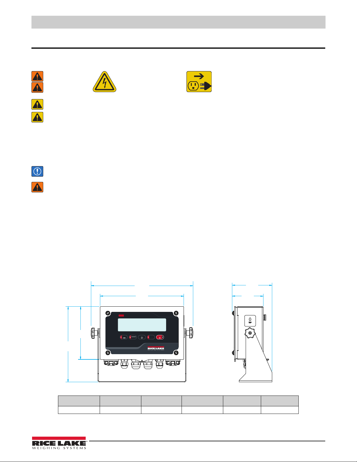
2.2 380 Product Dimensions
9.50 in (241 mm) 6.00 in (152 mm) 8.57 in (218 mm) 11.58 in (294 mm) 4.53 in (115 mm) 3.53 in (90 mm)
A B C D E F
Figure 2-1. 380 Product Diagram
Table 2-1. 380 Product Dimensions
© Rice Lake Weighing Systems ● All Rights Reserved 9
Page 10
380/381 Synergy Indicator
A
B
D
E
F
C
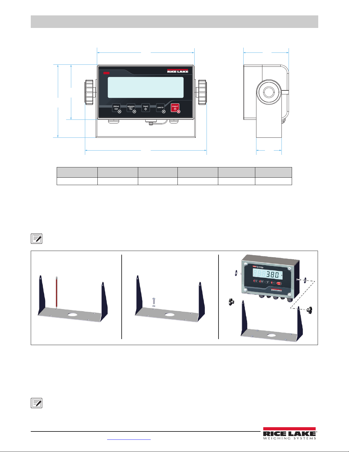
2.3 381 Product Dimensions
A B C D E F
6.77 in (172 mm) 3.82 in (97 mm) 5.06 in (129 mm) 8.50 in (216 mm) 3.17 in (81 mm) 1.77 in (45 mm)
Figure 2-2. 381 Product Diagram
Table 2-2. 381 Product Dimensions
2.4 Mounting Instructions
All 380/381 Synergy Series indicators include a universal mount stand. The 380 universal mount stand has 4 holes and the 381
stand has two holes. The stand can be mounted on a wall, tabletop or a flat surface. The instructions below are to be used as
an example for all models.
NOTE: The universal mount stand comes attached to the 380. Rice Lake Weighing Systems recommends removing the
indicator from the stand prior to mounting.
1. Using the mount as a template, mark the screw locations.
2. Drill holes for the screws.
3. Secure the universal mount using the appropriate length 1/4 in or M6 hardware (not included).
4. Reattach the 380/381 to the universal mount stand.
NOTE: The 380 parts kit includes rubber grommets to insert into the four screw holes of the universal mount stand for a
non-mounted application.
Figure 2-3. Mounting the Indicator
10 Visit our website www.RiceLake.com
Page 11
2.5 Open Enclosure
This section includes information on opening the 380 and 381 enclosures.
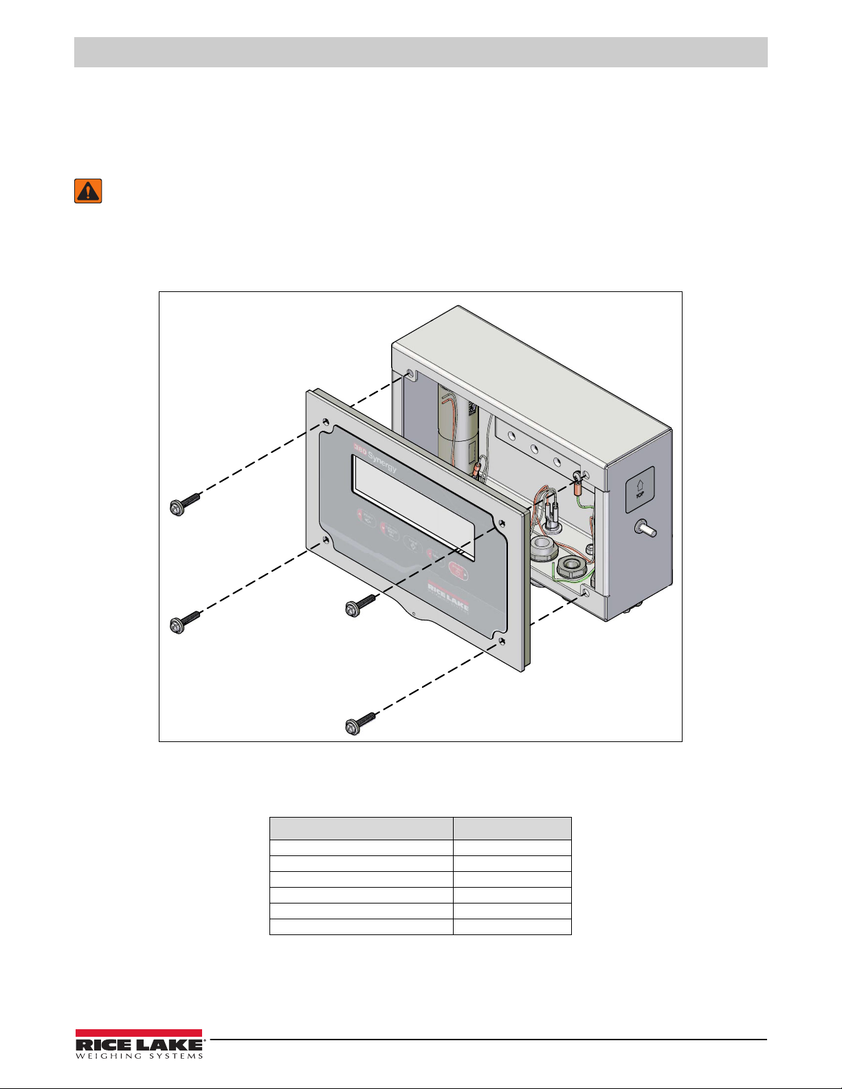
2.5.1 380 Front Plate Removal
Remove the front plate of the 380 to connect cables and to gain access to the 380 board.
WARNING: Before opening the unit, ensure batteries are removed and the optional power cord is disconnected from the
power outlet.
1. Place the indicator face-up on an anti-static work mat.
2. Remove the screws holding the front plate to the enclosure.
3. Lift the front plate away from the enclosure and disconnect the ground wire from the front plate.
Installation
Figure 2-4. Removing the Front Plate
380 Torque Ratings
Refer to Table 2-3 throughout installation and use of product to maintain proper torque ratings for 380 components.
Component Torque Rating
Front Plate Screw 10 in-lb (1.1 N-m)
Cord Grip Nut (to enclosure) 33 in-lb (3.7 N-m)
Cord Grip Dome Nut (around cable) 22 in-lb (2.5 N-m)
Screw at Antenna Hole 10 in-lb (1.1 N-m)
Grounding wire 10 in-lb (1.1 N-m)
Standoff Nuts 4 in-lb (0.45 N-m)
Table 2-3. Component Torque Ratings
© Rice Lake Weighing Systems ● All Rights Reserved 11
Page 12
380/381 Synergy Indicator
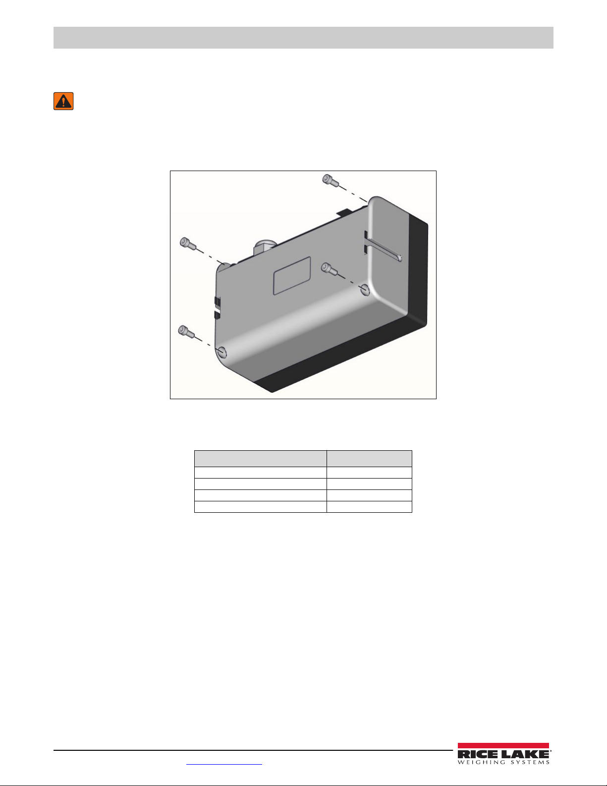
2.5.2 381 Back Plate Removal
Remove the back cover of the 381 to connect cables and to gain access to the 381 board.
WARNING: Before opening the unit, ensure power cord is disconnected from the power outlet.
1. Place the indicator face-down on an anti-static work mat.
2. Remove the screws holding the back cover to the enclosure with a 3mm hex key (PN 216647).
3. Lift the back cover away from the enclosure.
Figure 2-5. Removing the Back Plate
381 Torque Ratings
Refer to Table 2-4 throughout installation and use of product to maintain proper torque ratings for 381 components.
Component Torque Rating
Back Cover Screw 13 in-lb (1.5 N-m)
Cord Grip Nut (to enclosure) 33 in-lb (3.7 N-m)
Cord Grip Dome Nut (around cable) 22 in-lb (2.5 N-m)
Standoff Nuts 4 in-lb (0.45 N-m)
Table 2-4. Component Torque Ratings
12 Visit our website www.RiceLake.com
Page 13
Installation
2.6 Cord Grip Connections
Each of the models in the 380/381 Synergy Series indicator line utilizes a different cord grip configuration. Cable plugs for the
380 are included in the parts kit and must be installed in open cord grips to prevent moisture from entering the enclosure.
Depending on the application, install cables as required. 381 cord grip plugs are already installed. The recommended cable
strip length is 0.25 in (7 mm) for all 380/381 connectors.
WARNING: Only connect unit to equipment certified to IEC 60950, IEC 62368, IEC 61010 or similar.
IMPORTANT: Do not have open/bare wires outside of the enclosure. Make sure no stripped portion of cable is on the
outside of the cord grips.
IMPORTANT: Properly seal cord grips to prevent moisture damage inside of the enclosure. Cable plugs must be installed in
unused cord grips. Cord grip dome nuts, around a cable or a plug, must be torqued to 22 in-lb. The cord grip nut against the
enclosure must be torqued to 33 in-lb.
Cable Diameter Ranges
Refer to Table 2-5 for minimum and maximum cable sizes for use with cord grips.
Cord Grip Diameter Range
PG7 (PN 58983) 0.098 - 0.256 in (2.5 - 6.5mm)
PG9 (PN 15626) 0.138 - 0.315 in (3.5 - 8mm)
PG11 (PN 68600) 0.197 - 0.394 in (5 - 10 mm)
Table 2-5. Cord Grip Diameter Ranges
2.6.1 380 Cord Grip Connections (PN 202711)
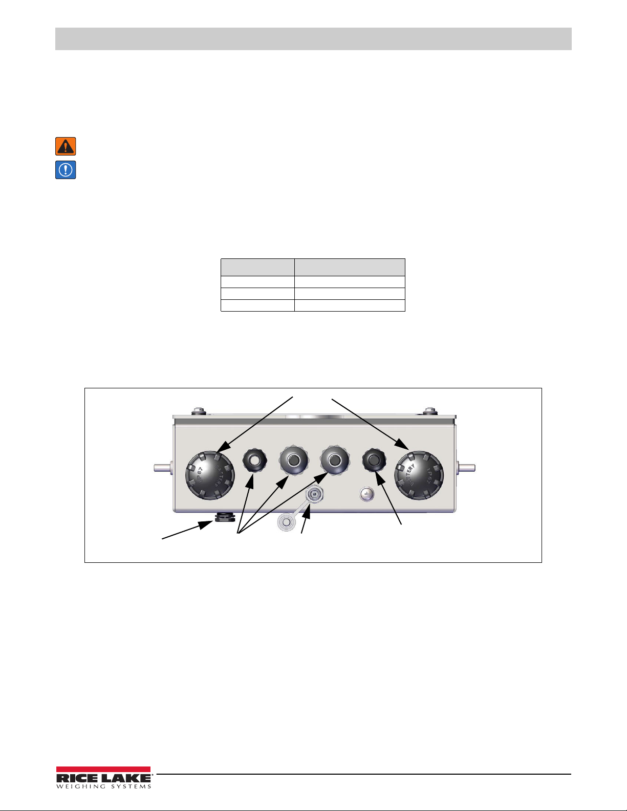
The 380 provides four cord grips at the bottom of the enclosure for cabling into the indicator. One of the cord grips is used for
the load cell and the other three are used to accommodate the serial connection and other future connections. See Figure 2-6
for the recommended assignments for the 380 cord grips.
Batteries
Cord grip for
Breather Vent
Cord grips for
communication cables
Figure 2-6. Recommended Cord Grip Assignments
Power Jack
load cell cable
© Rice Lake Weighing Systems ● All Rights Reserved 13
Page 14
380/381 Synergy Indicator
2.6.2 381-2D-AA Cord Grip Connections (PN 215695)
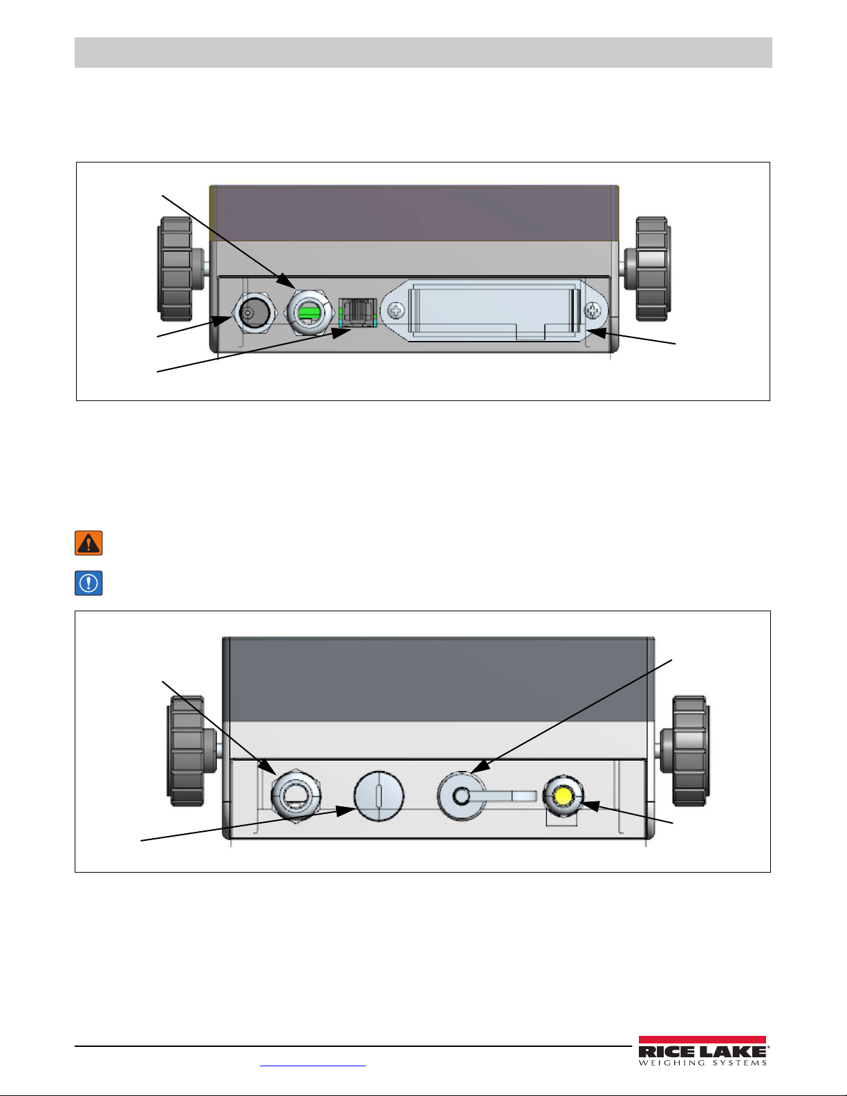
The 381-2D-AA provides one cord grip, a power jack and an RJ11/12 jack at the bottom of the enclosure for cabling into the
indicator. The cord grip is used for the load cell and the other connections are for power and serial connection. See Figure 2-7
for the recommended assignments for the 381-2D-AA connections.
Cord grip for
load cell cable
Power Jack
RJ11/12 Jack
Battery Door
Figure 2-7. Recommended Connection Assignments
2.6.3 381-2D-NiMH Cord Grip Connections (PN 185064)
The 381-2D-NiMH provides two cord grips and two other connections at the bottom of the enclosure for cabling into the
indicator. One of the cord grips is used for the load cell and the other three connections are used to accommodate the serial
connection, the battery charger and other future connections. See Figure 2-8 for the recommended assignments for the 3812D-NiMH connections.
WARNING: Only connect unit to equipment certified to IEC 60950, IEC 62368, IEC 61010 or similar.
IMPORTANT: Removal of the RJ-11/12 cover and the charger cap invalidate the IP rating of the unit.
Battery charger
Cord grip for
load cell cable
connector
RJ-11/12 Serial
connection
cover
Figure 2-8. Recommended Connection Assignments
14 Visit our website www.RiceLake.com
Cord grip for
optional
connectivity
Page 15
Installation
2.7 380 Cable Shield Grounding
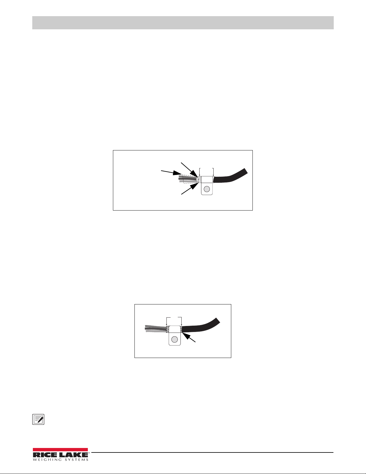
All cables routed through the cord grips on the 380 must be shield grounded against the grounding rail in the enclosure.
• Use M4 screws provided in the parts kit to install shielding clamps on the grounding rail at the back of the enclosure
• Install only the necessary amount of shielding clamps for the cord grips to be used
• Remove the insulated jackets and shielding per the following instructions
Shielding Procedure
1. Install the shielding clamps on the grounding rail using the clamp screws. Finger tighten the screws at this time.
2. Route the cables through the cord grips and the shielding clamps to determine the cable lengths required to reach the
appropriate cable connectors.
3. Mark cables to remove the insulated jacket as described below for Foil Shielded Cables and Braid Shielded Cables.
Foil Shielded Cables
Shield wire
Length of foil before
folding back on
cable insulation
Cut insulated jacket here
for foil shielded cables
Figure 2-9. Foil Shielded Cable
Silver
side out
1. Strip the insulated jacket and foil 1/2 in (15 mm) past the shielding clamp.
2. Strip another 1/2 in of the insulated jacket, leaving the foil shielding exposed.
3. Fold the foil shielding back on the cable where the cable passes through the clamp.
4. Ensure the silver (conductive) side of the foil is turned outward.
5. Wrap the shield wire around the cable, ensuring it contacts the foil where the cable passes through the clamp.
6. Torque the shielding clamp screw to 10 in-lb (1.1 N-m), ensuring the clamp is around the cable and contacting the
shield wire.
Braid Shielded Cables
Braid
Cut insulated
jacket here
Figure 2-10. Braid Shielded Cable
1. Strip the insulated jacket and braided shielding from a point just past the shielding clamp.
2. Strip another 1/2 in (15 mm) of the insulated jacket, leaving the braid exposed where the cable passes through the
clamp.
3. Torque the shielding clamp screw to 10 in-lb (1.1 N-m), ensuring the clamp is contacting the braided shielding of the
cable.
NOTE: The recommended cable strip length is 0.25 in (7 mm) for all 380/381 connectors.
© Rice Lake Weighing Systems ● All Rights Reserved 15
Page 16
380/381 Synergy Indicator
+SIG
-SIG
+SEN
MICRO-USB
-SEN
+EXC
-EXC
YC3
SW2
RTC
CN2
CN1
CN4
JP3
CN3
CN10
COM1 - RS-232
COM1
CAL
N/A
N/A
GND
+Vin
CN9
SENSE
N/A
N/A
GND
RX
TX
ON
OFF
1 2
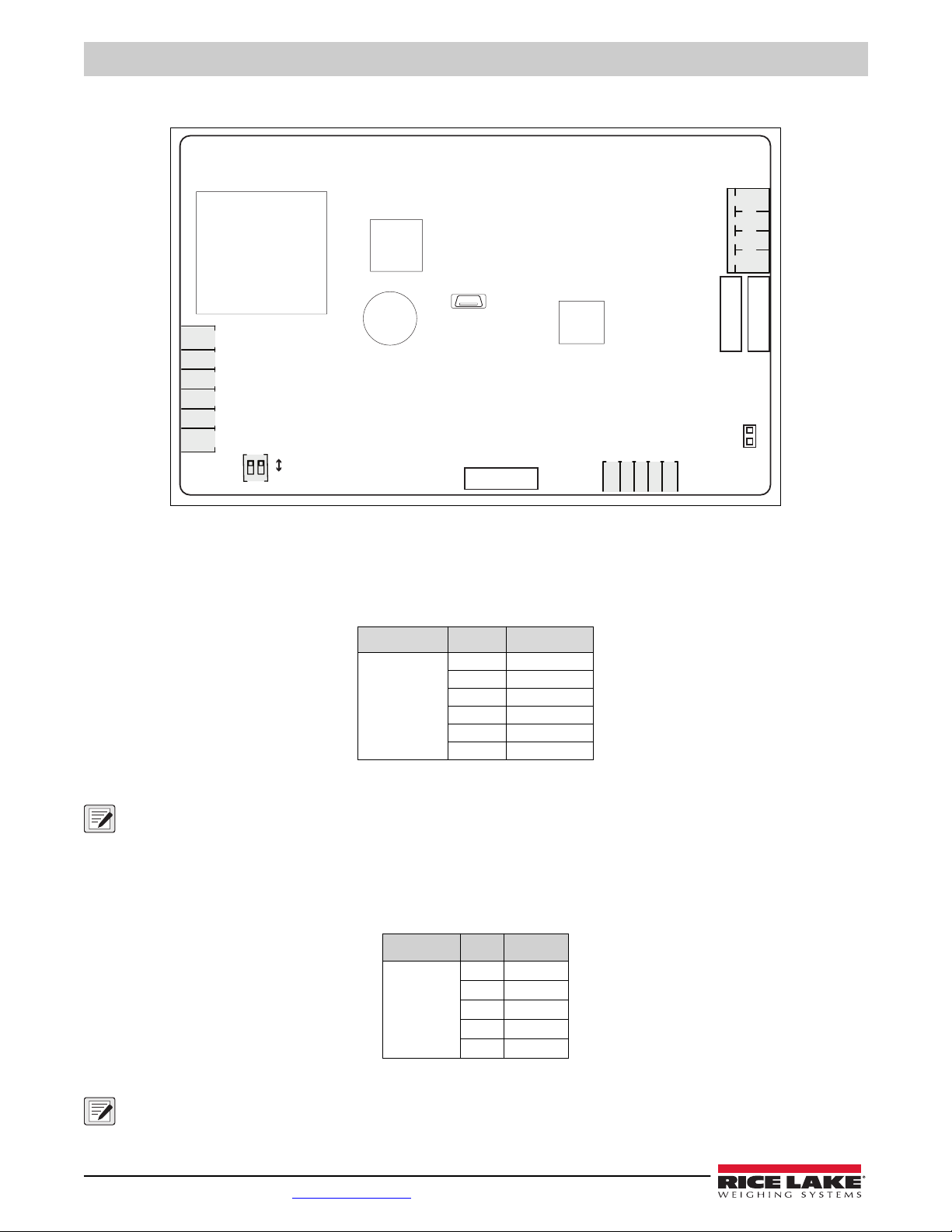
2.8 CPU Board Connections
Figure 2-11. CPU Board Connections
2.8.1 Load Cell Cable
To attach the cable from a load cell or junction box, route cable to the YC3 connector. See
from the load cell or junction box to connector.
Connector Pin Function
YC3 1 +SIG
2 –SIG
3 +SEN
4 –SEN
5 +EXC
6 –EXC
Table 2-6. YC3 Pin Assignments (Load Cell)
NOTE: For a 4-wire installation leave pins 3 and 4 empty on the connector.
NOTE: For a 6-wire installation set SW2 to all positions “off”, for 4-wire installation set all positions to “on.”
Table 2-6
for wiring the load cell cable
2.8.2 380 RS-232 Serial Communications
The CN10 connector is intended to provide a connection point for the RS-232 serial communications. One RS-232 port is
available. See Table 2-7 for the pin assignments for the CN10 connector.
Connector Pin RS232
CN10 1 TX1
Table 2-7. CN10 Pin Assignments (RS-232)
NOTE: This connection is available on the outside of the 381 enclosure via an RJ11/12 connector and optional
cable. (PN 215273). The serial connection can be made directly to the CN10 if the RJ-11/12 connection is not wanted.
16 Visit our website www.RiceLake.com
2 RX1
3 GND
4 N/A
5 N/A
Page 17
Installation
2.9 Power Connections
Power is connected to the power supply and the CPU board through the power harness.
Connector Pin Wire Power
CN1 1 Red +Vin
2 Black GND
3 N/A N/A
4 N/A N/A
Table 2-8. CN1 Alkaline Battery Pin Assignments (Power Supply)
2.9.1 380-2D Power Connections
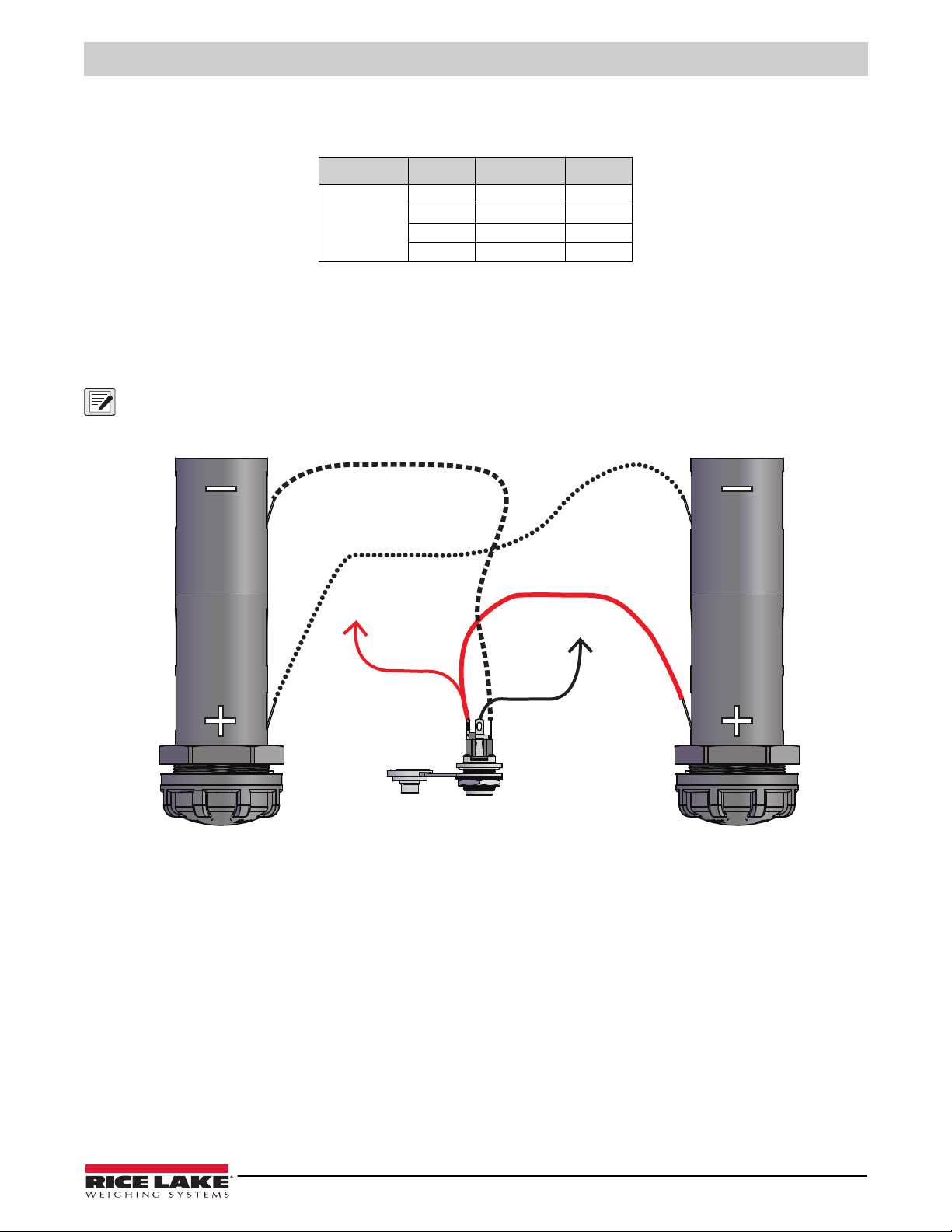
The 380 Synergy Indicator is powered by 4 C-Cell Batteries or an optional 12 V adapter (PN 206433). When the adapter is
inserted into the power jack, indicator power is disconnected from the battery holders and batteries no longer drain. The Power
adapter does not charge the batteries.
NOTE: Optional power adapter (PN 206433) is the only external power source allowed to be used.
NOTE: Ensure that battery covers are screwed finger tight. If covers are not fully screwed on, the indicator will not function.
Black wire to GND
Black Jumper Wire
Red Wire to Pin
Red wire to CN1
Pin 1
Table 2-8
Black wire to CN1
Pin 2
Table 2-8
Figure 2-12. 380-2D Battery Cell Wiring
© Rice Lake Weighing Systems ● All Rights Reserved 17
Page 18
380/381 Synergy Indicator
Battery Pack
NiMH Battery
CN1
2
1
4
3
2.9.2 381-2D-AA Power Connections
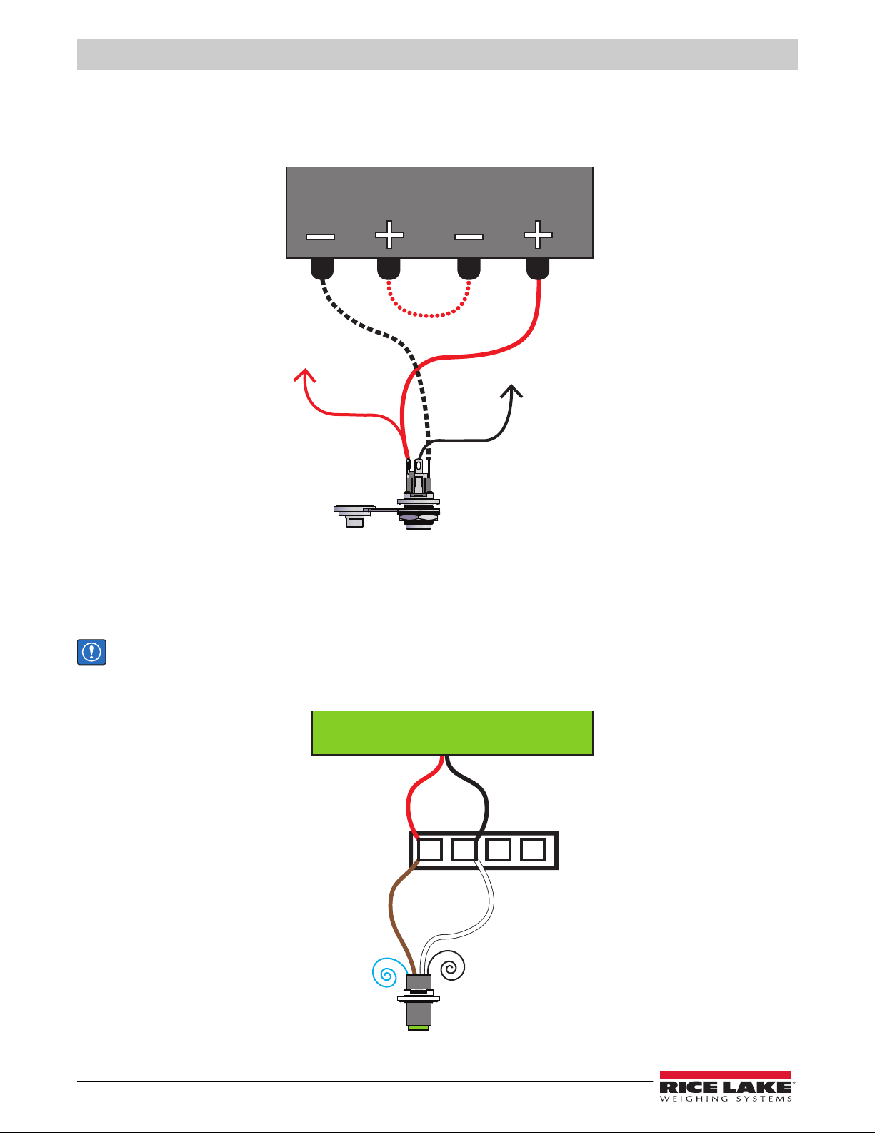
The 381-2D-AA Synergy Indicator is powered by 4 AA Batteries or an optional 12 V adapter (PN 215734). When the adapter is
inserted into the power jack, indicator power is disconnected from the battery holders and batteries no longer drain. The power
adapter does not charge the batteries.
Black wire
to GND
Red wire to CN1
Pin 1
Table 2-8 on page 17
Figure 2-13. 381-2D-AA Battery Cell Wiring
Red Jumper
Wire
Black wire to CN1
Pin 2
Table 2-8 on page 17
Red Wire to
+ on Battery
Pack
2.9.3 381-2D-NiMH Power Connections
The 381-2D-NiMH Synergy Indicator is powered by a rechargable NiMH battery. The Power adapter (PN 185064) charges the
battery.
IMPORTANT: The 381-2D-NiMH must not be powered on while battery is charging.
Leaving the charger attached to the 381-2D-NiMh while not plugged in will discharge the battery even if the indicator is
powered off.
Red Wire to
CN1 - Pin 1
Brown wire to
CN1 - Pin 1
18 Visit our website www.RiceLake.com
Figure 2-14. 381-2D-NiMH Battery Cell Wiring
Black wire to
CN1 - Pin 2
White wire to
CN1 - Pin 2
Black wire and
Blue Wire not
used
Page 19
Installation
2
1
4
3
2
1
4
3
2.10 Reassembly
Once work inside of the enclosure is complete, reattach the front plate ground wire to the front plate.
2.10.1 380 Front Plate Reattachment
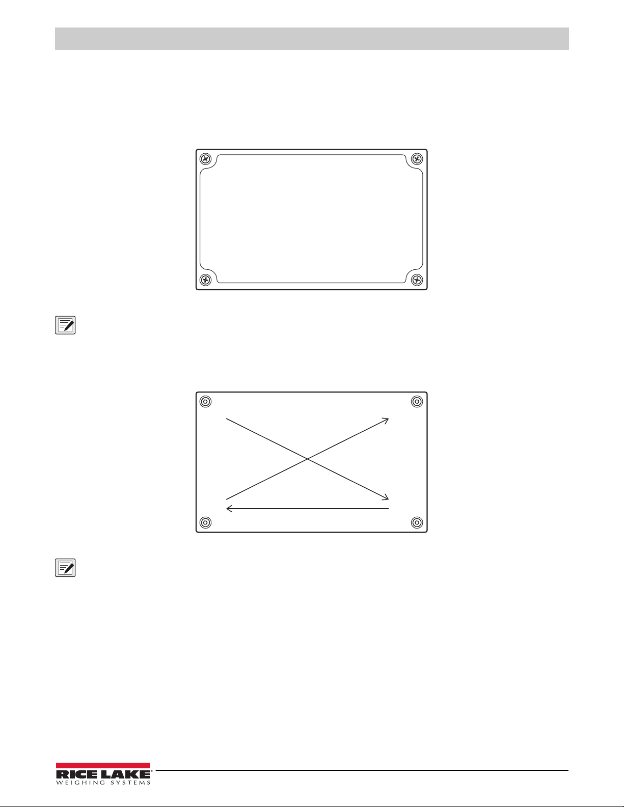
Position the front plate over the enclosure and install the four front plate screws with a Philips head screw driver. Use the torque
pattern in Figure 2-15 to prevent distorting the front plate gasket. Torque screws to 10 in-lb (1.1 N-m).
Figure 2-15. 380 Front Plate Torque Pattern
NOTE: Torqued screws may become less tight as the gasket is compressed during the torque pattern; a second torque is
required using the same pattern and torque value.
2.10.2 381 Reassembly
Position the Back cover over the enclosure and install the four screws with a 3mm hex key (PN 216647). Use the torque pattern
in Figure 2-16 to prevent distorting the gasket on the 381-2D-NiMH. Torque screws to 13 in-lb (1.5 N-m).
Figure 2-16. 381 Torque Pattern
NOTE: Torqued screws may become less tight as the gasket is compressed during the torque pattern; a second torque is
required using the same pattern and torque value.
© Rice Lake Weighing Systems ● All Rights Reserved 19
Page 20
380/381 Synergy Indicator
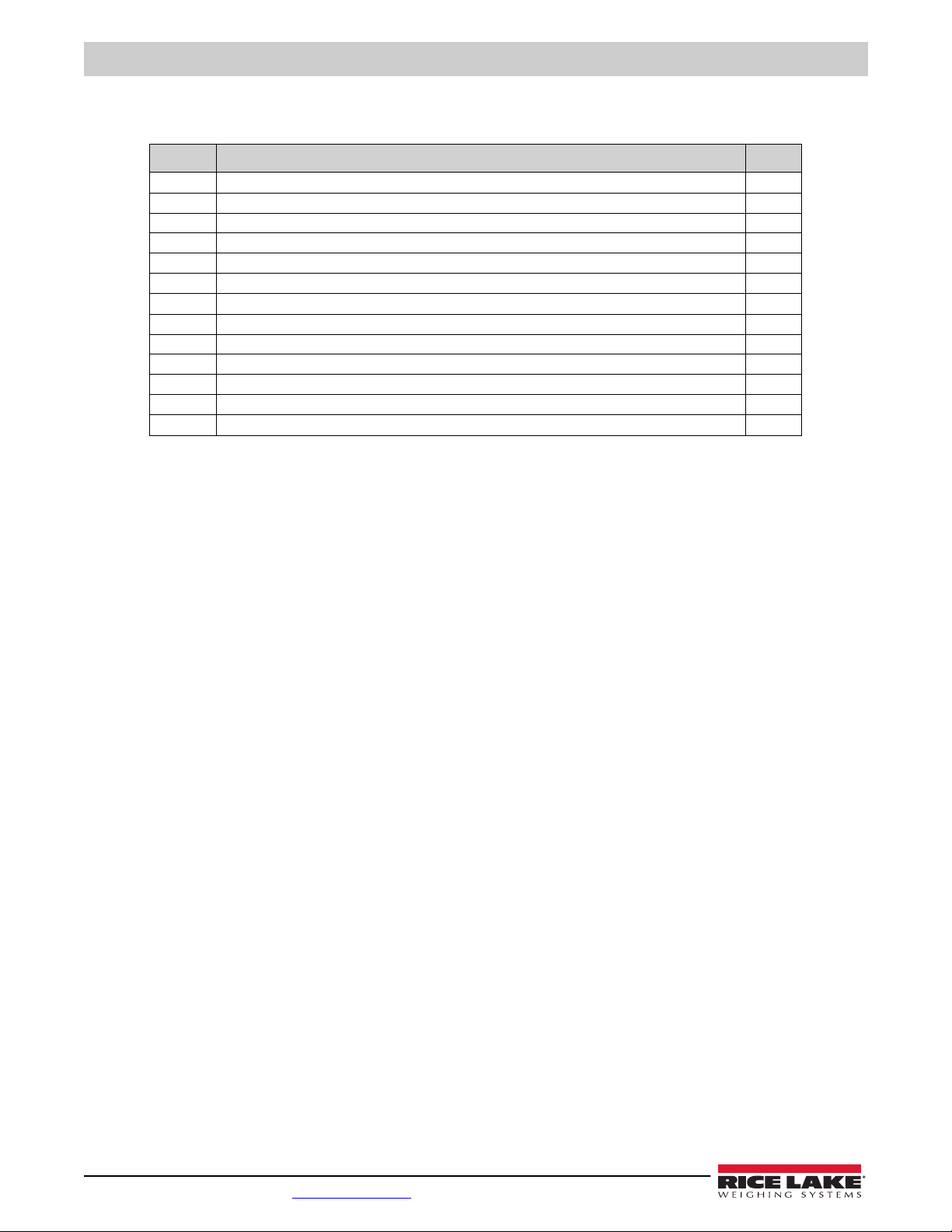
2.11 380 Parts Kit Components
Part No. Description Qty.
108945 SCREW, M3 x 0.5 x 8 mm Phillips Flat Countersunk Stainless Steel Machine Screw 1
15631 CABLE TIE, 3 in Nylon 4
15650 MOUNT, 3/4 in Cable Tie Mount 2
15664 GLAND, Reducing 9 mm-3/8NPT 2
192586 FRAME, Jumper Protection 1
19538 POST PLUG, 1/4 in x 1.00 Slotted Black Plastic 3
202140 SCREW, M4 x 0.7 x 10 Phillips Pan Head Zinc Finish Steel SEMS Screw with External Tooth Washer 3
28325
30632
42149 BUMPER, 0.50 OD x 0.281 ID Rubber Grommet 4
53075 CLAMP, Ø0.078 in Ground Cable Shield 4
67550 CLAMP, Ø0.125 in Ground Cable Shield 2
94422 LABEL, 0.40 x 5.00 Capacity Label 1
BAG, 2 x 3 2-Mil Write On, Ziploc Style Plastic Bag
BAG, 5 x 8 2-Mil Ziploc Style Plastic Bag
Table 2-9. 380 Parts Kit (PN 205840) Components
1
1
20 Visit our website www.RiceLake.com
Page 21
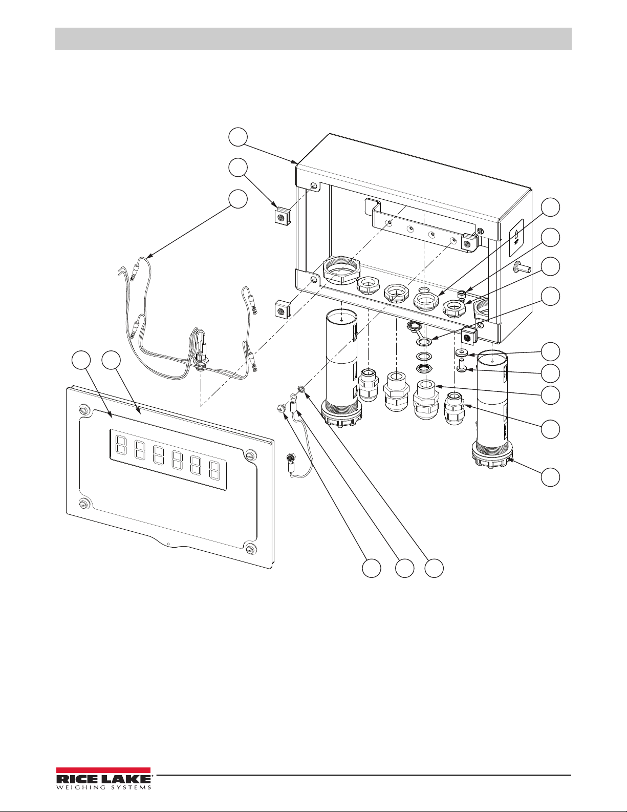
2.12 Replacement Parts
5
12
19
6 1
31
29
10
13
30
11
9
8
222423
4
Installation
Figure 2-17. 380 Replacement Parts Diagram ― Front View
© Rice Lake Weighing Systems ● All Rights Reserved 21
Page 22
380/381 Synergy Indicator
1413
32
3215
222124
19 20
7
25 26
17
18
16
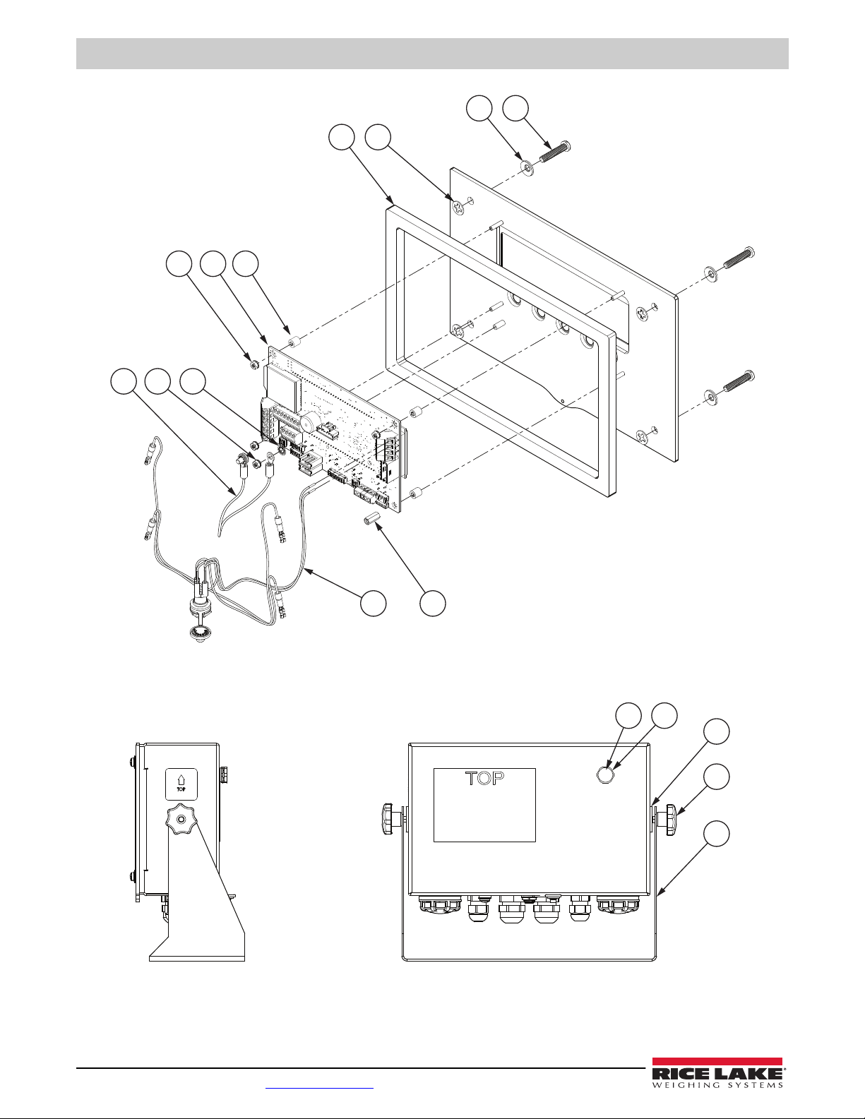
Figure 2-18. 380 Replacement Parts Diagram ― Rear View
Figure 2-19. 380 Replacement Parts Diagram ―Side View
22 Visit our website www.RiceLake.com
Page 23
Installation
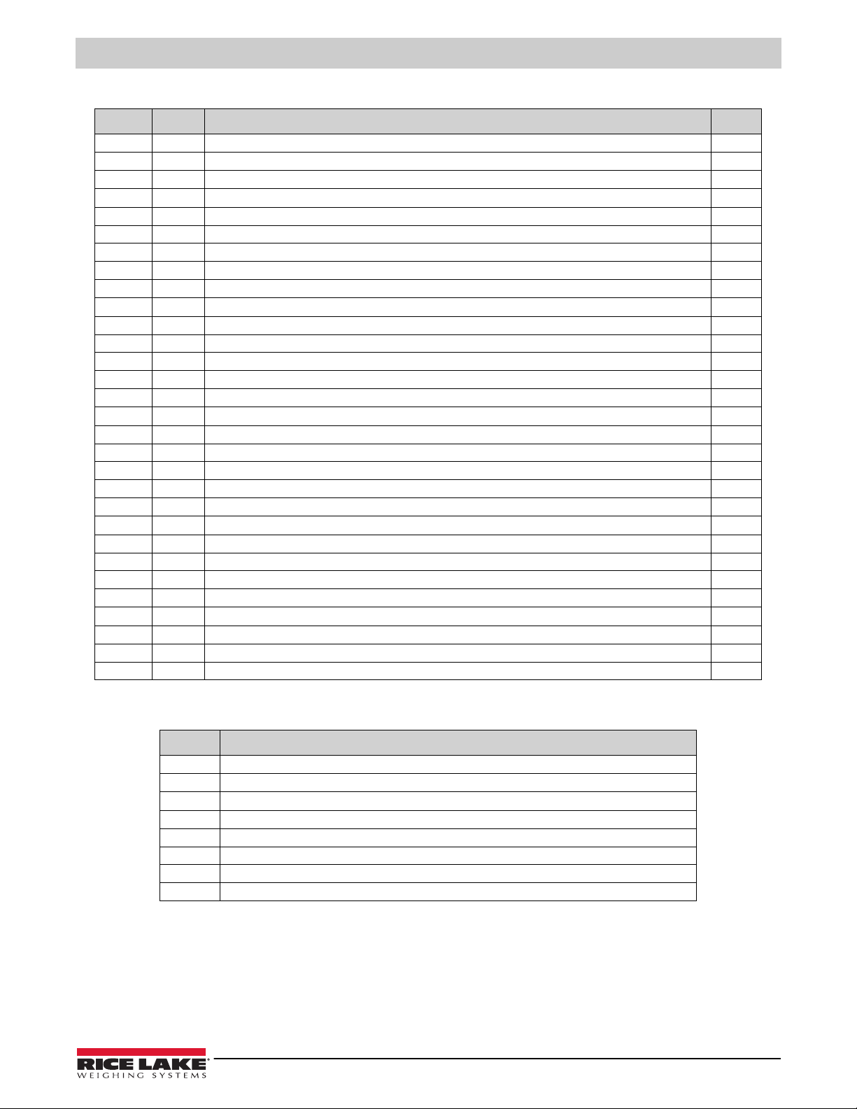
Item No. Part No. Description Qty.
1 201041 FRONT COVER, 380 Universal Battery Powered 1
2 206406 BOARD ASSEMBLY, Replacement 380 CPU, RoHS Compliant 1
3 202064 SPACER, M3 x Ø0.250 x 0.260 Round Nylon 4
4 205136 HOLDER, BATTERY 2C, C-Size Battery Holder, Front Panel, IP67 2
5 201040 ENCLOSURE, 380 Universal Battery Powered 1
6 202824 OVERLAY, 380 Synergy Indicator 1
7 203691 GASKET, 380 Synergy Battery Powered Indicator 1
8 15626 CORD GRIP, PG9 Plastic 2
9 15627 LOCKNUT, PG9 Plastic 2
10 68600 CORD GRIP, PG11 2
11 68601 NUT, PG11 Black Nylon 2
12 205800 NUT, M5 x 0.8 Clip on Floating Hex Zinc Plated 4
13 46381 WASHER, #10 18-8 Bonded Sealing Stainless Steel 5
14 205687 SCREW, M5 x 0.8 x 25 mm Phillips Drilled Cheese Head Stainless Steel Machine Screw 4
15 202061 NUT, M3 x 0.5 Hex Kep Stainless Steel 3
16 29635 STAND, Stainless Steel Tilt 1
17 103988 WASHER, 0.515-0.52 Nylon 2
18 180825 KNOB, 32 mm Diameter, Nylon Knob, M6 x 1 Threaded Thru, Stainless Stee 2
19 204557 CABLE ASSEMBLY, 380 Synergy Power Harness 1
20 205753 STANDOFF, M3 x 0.5 x 12 mm F/F Nickel Plated Brass 1
21 180826 NUT, M4 x 0.7 Kep Nut with 18-8 Stainless Steel External Tooth Lock Washer 1
22 180856 WASHER, M4 Internal Tooth Stainless Steel 2
23 194488 SCREW, M4 x 0.7 x 6 Phillips Pan Head Zinc Finish Steel External Tooth Washer Sems Machine Screw 1
24 40672 WIRE, 9 in Ground Wire with #8 Eye Connector 1
25 88733 VENT, Black Plastic Gortex Sealed Breather 1
26 88734 NUT, M12 x 1 Thread Breather Vent 1
29 150800 SCREW, M5 x 0.8 x 10 Stainless Steel Phillips Pan Head Machine Screw 1
30 187876 NUT, M5 Nylon Insert Stainless Steel Lock Nut 1
31 205294 SEAL, Power Jack Seal Cap 1
32 205884 WASHER, M5 x 0.177 ID x 0.453 OD x 0.032 Nylon Self-Retaining 4
Table 2-10. 380 Replacement Parts
Part No. Description
216778 CABLE ASSY, Power Harness 381 Synergy NiMH
216779 CABLE ASSY, Power Harness 381 Synergy AA
216780 TRAY, Removable, Batt Holder 381 Synergy AA
216781 BATTERY, NiMH, Internal 6 V 4.5 Ah, 381 Synergy
216782 BOARD ASSY, Serial RJ11 381 Synergy
216783 KNOB, Side 381 Synergy {black cap)
216784 INSERT, Side Knob 381 Synergy (metal insert)
216814
GASKET, Seal 381 Enclosure IP68 (381-2D-NiMH Only)
Table 2-11. 381 Replacement Parts
© Rice Lake Weighing Systems ● All Rights Reserved 23
Page 24
380/381 Synergy Indicator
ZERO
GROSS
NET
B/N
TARE
T
UNITS
PRINT
3.0 Operation
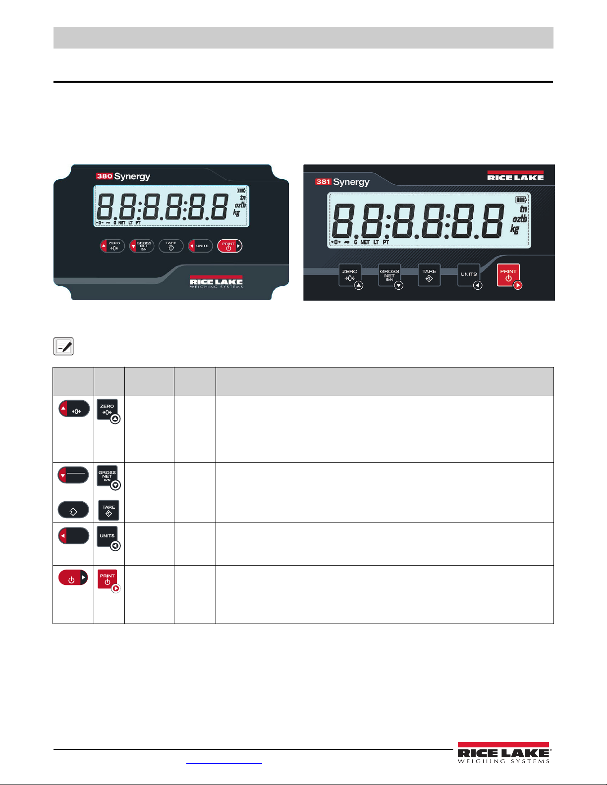
The front panel consists of a seven-segment LCD display with six 1.0 in (25 mm) tall digits. A negative number displays as five
digits plus the negative symbol. The front panel also includes five flat panel keys, backed by tactile primary scale function buttons
with an integrated power button. There are annunciators built into the LCD screen that show units and scale functions.
3.1 Front Panel
380 Synergy Front Panel 381 Synergy Front Panel
Figure 3-1. 380/381 Synergy Series Front Panels
NOTE: All procedures in this manual use the 380 keys to illustrate functions. When operating a 381 Synergy product, use
the corresponding buttons below.
380 Key
381
Key
Menu
Navigation
Move UP
menu
structure
Move DOWN
menu
structure
- Confirm
Move LEFT
in menu
structure
Move RIGHT
in menu
structure
Numeric
Entry Weigh Mode Function
Increase
digit value
Decrease
digit value
Delete
current
digit and
move left
Move right
one digit
Sets the current gross weight to zero, provided the amount of weight to be removed or added is within
the specified zero range and the scale is not in motion; the zero band is defaulted to 1.9% of full scale,
by 1
but can be configured for up to 100% of full scale;
hold five seconds to enter user mode when unit is already powered on
IMPORTANT: Do not hold during power up. Indicator enters update firmware mode if zero is held
during power up. (Section 9.5.2 on page 52)
Switches the display mode from gross to net, or from net to gross; If a tare value has been entered or
acquired, the net value is the gross weight minus the tare; gross mode is represented by the G annunci-
by 1
ator; net mode is represented by the NET annunciator
Performs one of several predetermined Tare functions dependent on the mode of operation selected in
digit
the TARE FN parameter;
Switches the weight display to an alternate unit; The alternate unit is defined in the Configuration menu,
and could be kg, g, lb, oz, tn or t;
Turns the unit ON/OFF:
If ON, press and hold for five seconds to turn unit OFF
If OFF, press and hold for two seconds to turn unit ON
Press momentarily to send on-demand print format out the configured port, provided the conditions for
standstill are met; RS 232 is default port
Table 3-1. Buttons and Descriptions
24 Visit our website www.RiceLake.com
Page 25
Operation
UNITS
PRINT
ZERO
GROSS
NET
B/N
TARE
T
ZERO
ZERO
GROSS
NET
B/N
UNITS
PRINT
TARE
T
3.2 LCD Annunciators
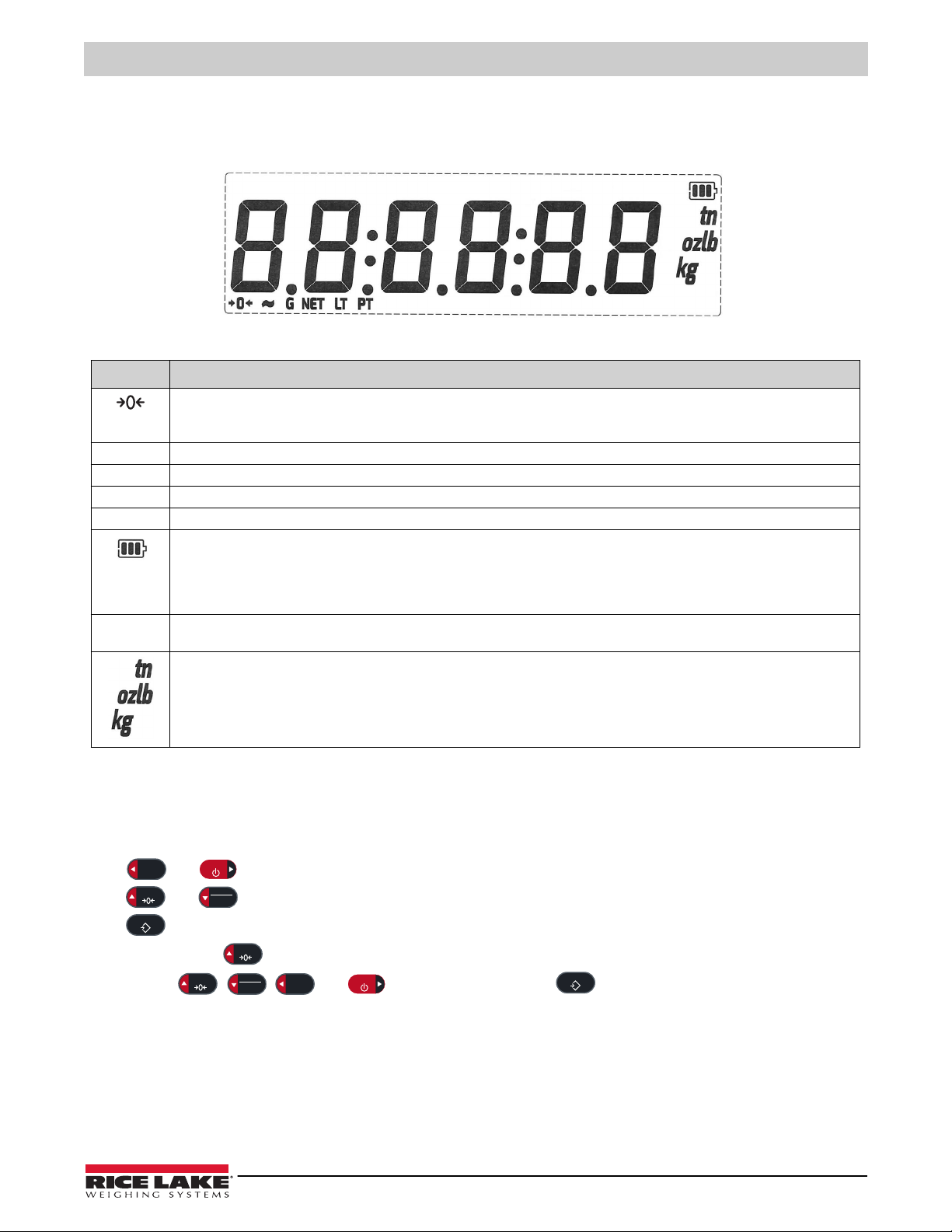
The 380/381 display uses LCD annunciators to provide additional information about the value being displayed and battery
status.
Figure 3-2. LCD Display
LCD Description
The Center of Zero annunciator – Indicates the current gross weight reading is within ± 0.25 display divisions of the acquired zero;
A display division is the resolution of the displayed weight value, or the smallest incremental increase or decrease which can be dis-
played or printed
G
Net
LT
PT
Gross annunciator - Gross weight display mode
Net annunciator – Net weight display mode
Tare annunciator – Indicates a push-button tare weight has been acquired and stored in memory
Preset Tare annunciator – Indicates a preset tare weight has been keyed in or entered and stored in memory
Battery annunciator – Indicates remaining battery capacity
• 3 bars - >95% capacity remaining
• 2 bars - 5-95% capacity remaining
• 1 bar - 1-5% capacity remaining
• 0 bars - <1% capacity remaining
Unstable annunciator – Scale is unstable or outside the specified motion band; Some operations, including zero, tare and print, can only
~
be done when the unstable annunciator is off
Unit displayed annunciator – Displays which unit of measure is being used; units available are lb (pounds), kg (kilograms) t (tonnes),
g (grams), tn (short ton), oz (ounce)
Table 3-2. LCD Annunciators
3.3 General Navigation
The front panel scale function buttons are also used to navigate through the menu structure.
• and move left and right (horizontally) in a menu level
• and move up and down to different menu levels and to exit a menu
• enters a menu or parameter and selects/saves parameter settings or values if in a value entry mode
• Press and hold for five seconds to access user mode
• Use the , , and to enter a value and press to accept the value
© Rice Lake Weighing Systems ● All Rights Reserved 25
Page 26
380/381 Synergy Indicator
GROSS
NET
B/N
UNITS
PRINT
ZERO
GROSS
NET
B/N
TARE
T
UNITS
PRINT
TARE
T
ZERO
GROSS
NET
B/N
UNITS
PRINT
TARE
T
GROSS
NET
B/N
GROSS
NET
B/N
UNITS
PRINT
ZERO
ZERO
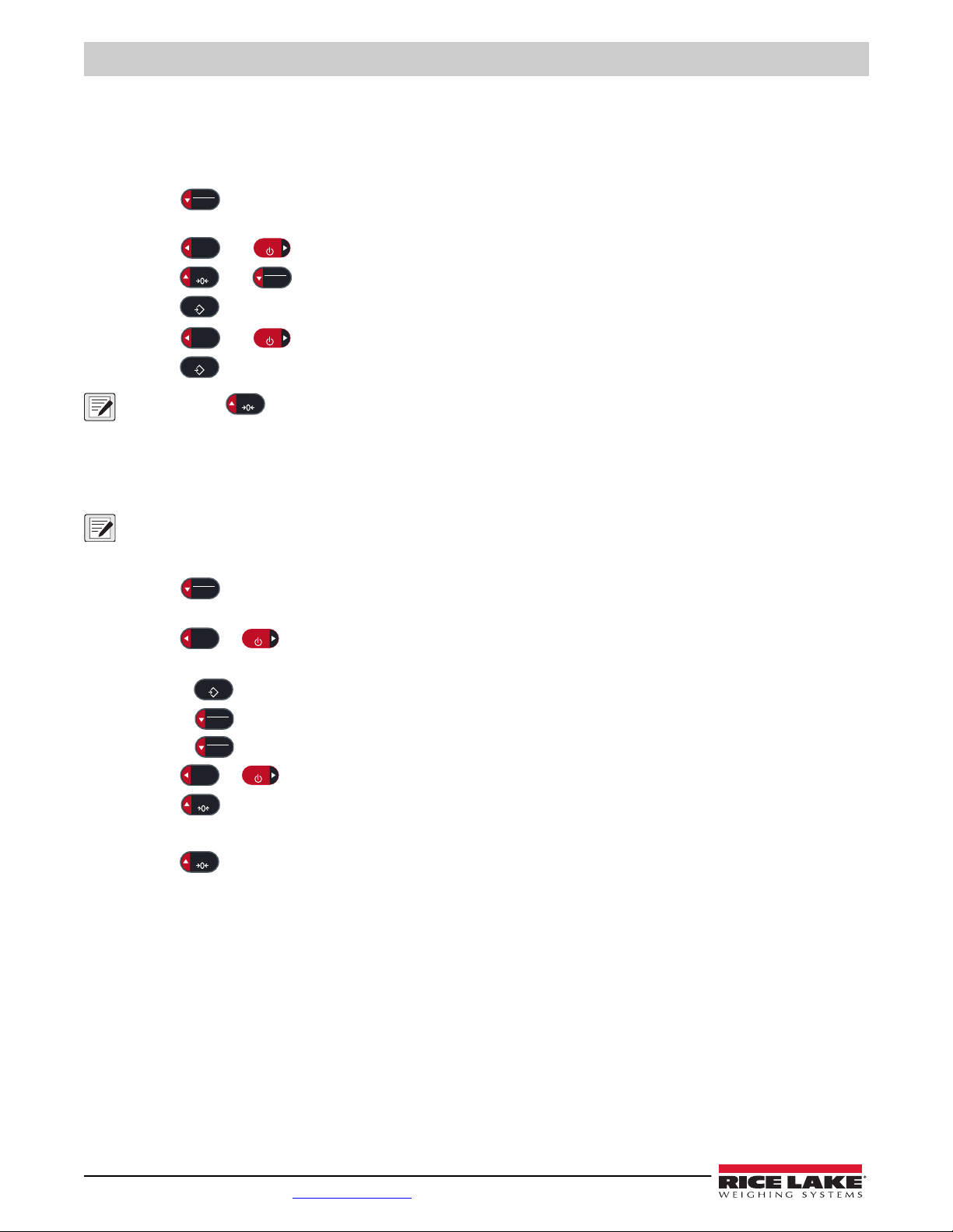
3.3.1 Numeric Value Entry
Several parameters in the menu structure require the entry of a numeric value rather than the making of a selection. Numbers
are entered in two steps. First the numeric digits are entered, then the decimal point is positioned.
Follow this procedure to enter a numeric value:
1. Press
to enter into a parameter. The current parameter value displays. The current position in the string
continuously blinks.
2. Press and to change location of flashing digit. Adjust digit as follows until desired number is selected.
3. Press and to change the flashing digit.
4. Press to save numeric digits. Decimal position slowly flashes.
5. Press and to change the location of the decimal.
6. Press to confirm the new value and exit editor. The next parameter in the menu displays.
NOTE: Pressing also saves the new value. The next parameter in the menu displays.
NOTE: There is no decimal place to the right of the right-most digit.
3.3.2 Alphanumeric Entry
Several parameters in the menu structure require the entry of an alphanumeric value rather than the making of a selection.
NOTE: The end of the alphanumeric character string is indicated by the “_” character symbol.
Follow this procedure to enter an alphanumeric value:
1. Press
continuously blinks.
2. Press
3. Perform one of the following actions:
to enter into a parameter. The current parameter entry displays. The current position in the string
or to change the blinking character to be edited.
• Press to add a new character or space to the left of the blinking character
• Press
twice to delete blinking character
• Press once to edit blinking character; Proceed to next step
4. Press
5. Press
or to scroll through available ASCII characters (Table 10-4 on page 58).
to accept character edit. The next character to the right continuously blinks.
6. Repeat the previous steps until alphanumeric entry is complete.
7. Press to confirm current string and exit editor. The next parameter in the menu displays.
26 Visit our website www.RiceLake.com
Page 27
Operation
ZERO
PRINT
PRINT
PRINT
UNITS
GROSS
NET
B/N
TARE
T
ZERO
TARE
T
ZERO
TARE
T
TARETTARE
T
TARE
T
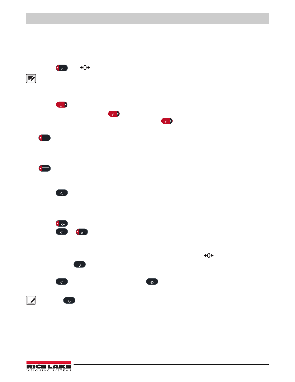
3.4 Weigh Mode Operation
This section summarizes basic 380/381 operations.
3.4.1 Zero Scale
1. In gross mode, remove all weight from the scale and wait for the "~" annunciator to turn off.
2. Press . The displays to indicate the scale is zeroed.
NOTE: The scale must be stable and within the configured zero range for the scale to be zeroed. If the scale cannot be
zeroed, see Section 10.1 on page 53.
3.4.2 Print Ticket
1. Wait for the "~" annunciator to turn off.
2. Press to send data to the configured port. The default print port is RS-232.
"~" annunciator is displayed when the is pressed, the print action only occurs if the scale comes out of motion within
If the
three seconds. If the scale stays in motion for over three seconds, the press is ignored.
3.4.3 Toggle Units
Press to toggle between primary and secondary units. The LCD annunciator representing the current unit is displayed.
3.4.4 Toggle Gross/Net Mode
Net mode is available when a tare value has been entered or acquired (Net = Gross minus Tare). If tare has not been entered
or acquired, the display remains in gross mode. The LCD annunciator G or NET indicates the current mode.
Press to toggle the display mode between gross and net.
3.4.5 Acquire Tare
1. Place a container on the scale and wait for the "~" annunciator to turn off.
2. Press to acquire the tare weight of the container. Then Net weight displays, and the Net and LT annunciators
are displayed.
3.4.6 Remove Tare Value
1. Remove all weight from the scale and wait for the "~" annunciator to turn off. The display reads the negative tare value.
2. Press to zero the scale, if needed.
3. Press (or in OIML mode). Display changes to gross weight and the Gross annunciator turns on.
3.4.7 Preset Tare (Keyed Tare)
Tare mode must be set to keyed or both for the preset tare feature to function.
1. Remove all weight from the scale and wait for the the
2. Press and hold for five seconds. Indicator will enter numeric entry mode.
3. Use the navigation keys to enter the tare weight value. See Section 3.3.1 on page 26.
4. Press to terminate numeric entry mode; press a second time to terminate preset tare entry mode.
5. The display changes to net weight, the Net and PT annunciators display.
NOTE: Press again while the "~" annunciator is off, or enter a keyed tare of zero to remove the preset tare value.
"~" annunciator to turn off and annunciator to display.
© Rice Lake Weighing Systems ● All Rights Reserved 27
Page 28
380/381 Synergy Indicator
ZERO
UNITS
PRINT
GROSS
NET
B/N
GROSS
NET
B/N
ZERO
ZERO
UNITS
PRINT
GROSS
NET
B/N
PRINT
GROSS
NET
B/N
ZERO
ZERO
GROSS
NET
B/N
GROSS
NET
B/N
ZERO
ZERO
UNITS
PRINT
GROSS
NET
B/N
GROSS
NET
B/N
ZERO
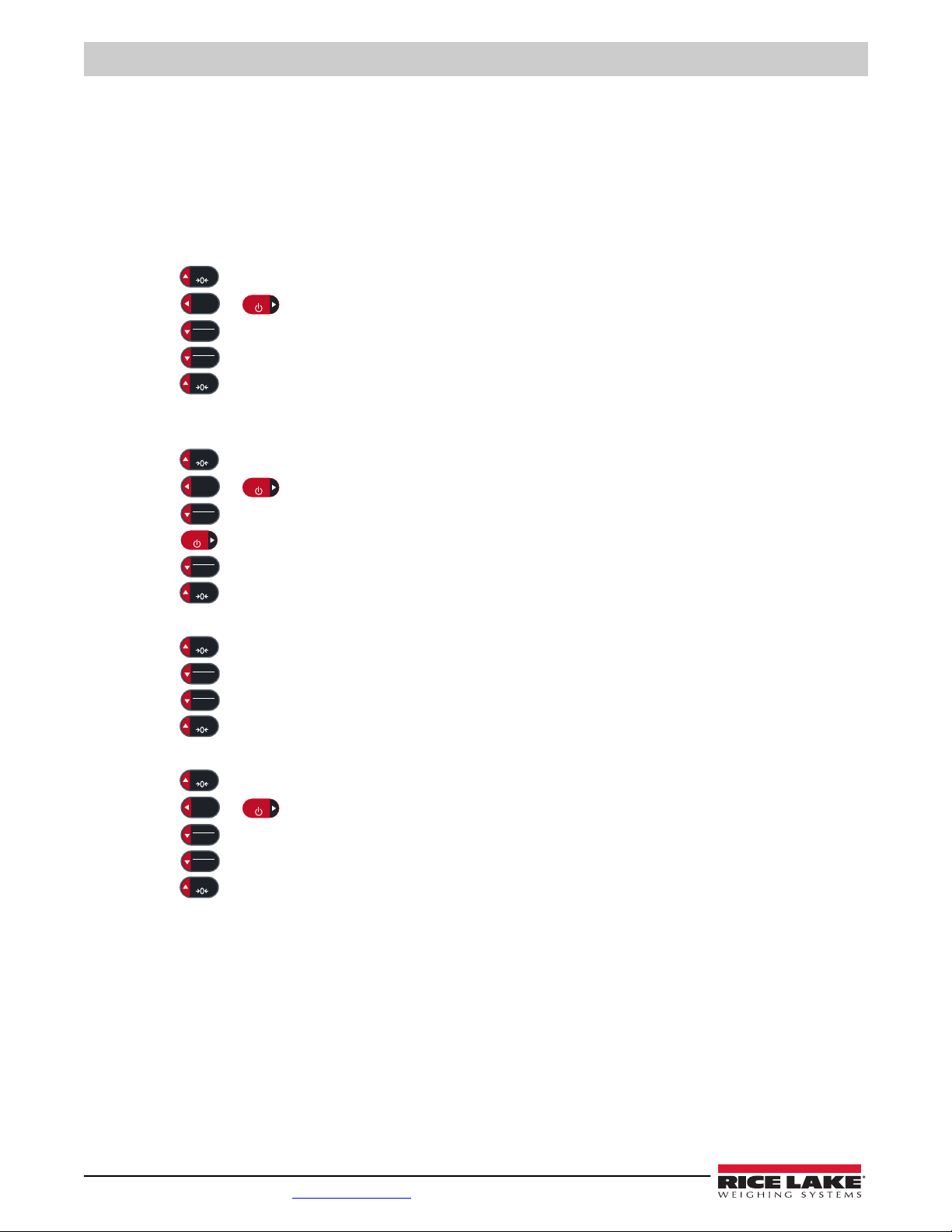
3.5 User Mode Menu
User Menu provides access to all menus in Section 4.0 on page 30 except for the Setup menu. For more information on each of
the menus, see the following sections:
• Audit Menu - Section 4.3 on page 32
• Accumulator Menu - Section 4.5 on page 39
• Tare Menu - Section 4.5 on page 39
3.5.1 Display a Stored Tare
1. Press for five seconds to enter user mode. Audit displays.
2. Press or until tare displays.
3. Press to enter tare menu. dsptar displays.
4. Press to display the stored tare value.
5. Press four times to return to weigh mode.
If there is not a tare in the system, the value displayed is zero.
3.5.2 Clear a Stored Tare
1. Press for five seconds to enter user mode. Audit displays.
2. Press or until tare displays.
3. Press to enter tare menu. dsptar displays.
4. Press . clrtar displays.
5. Press to clear the stored tare value. ok displays.
6. Press three times to return to weigh mode.
3.5.3 View Legally Relevant Version
1. Press for five seconds to enter user mode. Audit displays.
2. Press . lrv displays.
3. Press . The legally relevant version displays.
4. Press three times to return to weigh mode.
3.5.4 Display Accumulator
1. Press for five seconds to enter user mode. Audit displays.
2. Press or until accum displays.
3. Press . dspacm displays.
4. Press . The accumulator value displays.
5. Press three times to return to weigh mode.
28 Visit our website www.RiceLake.com
Page 29
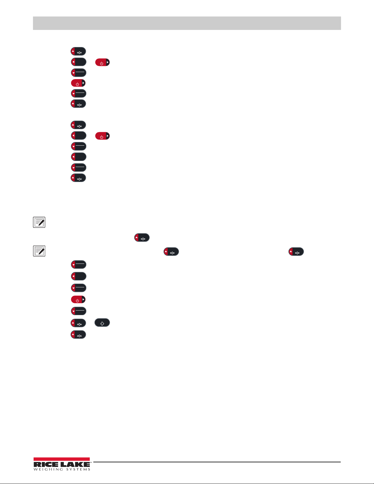
3.5.5 Print Accumulator
ZERO
UNITS
PRINT
GROSS
NET
B/N
PRINT
GROSS
NET
B/N
ZERO
ZERO
UNITS
PRINT
GROSS
NET
B/N
UNITS
GROSS
NET
B/N
ZERO
ZERO
ZERO
ZERO
GROSS
NET
B/N
UNITS
GROSS
NET
B/N
PRINT
GROSS
NET
B/N
ZERO
TARE
T
ZERO
1. Press for five seconds to enter user mode. Audit displays.
2. Press or until accum displays.
3. Press . dspacm displays.
4. Press . prtacm displays.
5. Press to print the accumulator value. ok displays.
6. Press three times to return to weigh mode.
3.5.6 Clear Accumulator
1. Press for five seconds to enter user mode. Audit displays.
2. Press or until accum displays.
3. Press . dspacm displays.
4. Press . clracm displays.
5. Press to clear the accumulator value. ok displays.
6. Press three times to return to weigh mode.
3.6 Reset (Default) Configuration
Perform the following to reset the indicator to factory settings:
NOTE: In order to reset the indicator to factory configured settings, the indicator must be in the Setup Menu (see
Section 4.0 on page 30) and the CAL jumper must be removed (see Section 4.1 on page 30).
Operation
1. Access setup mode by pressing once during the startup sequence. SETUP displays.
NOTE: When accessing Setup mode, only press once. Do not press and hold or double press .
2. Press . ConFig displays.
3. Press .
4. Press .
5. Press .
6. Press to reset the configuration.
7. Press or .
dEflt displays.
no displays.
yes displays.
ok displays.
no displays.
8. Press three times to return to weigh mode.
© Rice Lake Weighing Systems ● All Rights Reserved 29
Page 30
380/381 Synergy Indicator
ZERO
ZERO
ZERO
ZERO
ZERO
4.0 Configuration
There are two types of configuration parameters in the 380/381, setup mode parameters (or Legal for Trade configuration) and
user mode parameters (or non-legal configuration).
• The Setup mode parameters are accessed by pressing momentarily during the startup sequence. Only press
once. Do not press and hold or double press . All menus in this section can be accessed from within Setup
mode.
• The User mode can be accessed by pressing for five seconds. User mode includes all menus in this section other
than the setup menu.
NOTE: The key press must end before start-up is complete.
NOTE: CAL jumper must be removed to access Setup mode parameters (see Section 4.1).
The following sections provide graphic representations of the 380/381 menu structures. Most menu diagrams are accompanied
by a table which describes all parameters and parameter values associated with the menu. The factory default setting appears
in bold type.
NOTE: All weight related parameters must be configured prior to calibrating the unit.
4.1 Seal the Indicator
Access to setup mode is typically allowed through
pressing momentarily during the power up sequence. In certain Legal
for Trade applications it is necessary to restrict access to setup mode. This restriction is accomplished in two steps. First the
firmware access to Setup mode must be restricted by shorting the JP3/CAL jumper on the CPU board. Then the enclosure must
be secured with tamper proof seal. The 380/381 all use the same method to restrict access.
NOTE: In certain Legal for Trade applications it is necessary to seal the indicator to restrict access to the CAL jumper.
Breaking of the seal terminates the Legal for Trade status of the indicator because the seal limits access to the
configuration menu.
4.1.1 Close the CAL Jumper
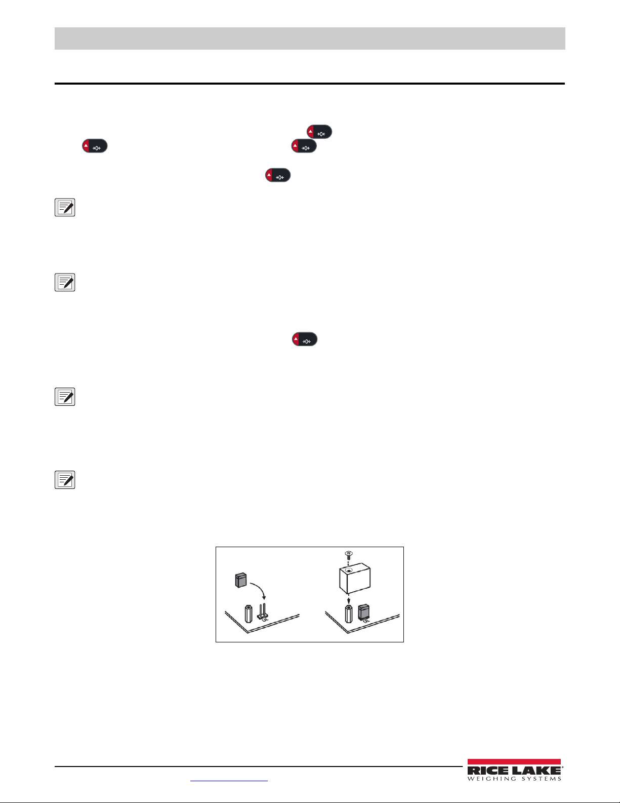
With the jumper open, the 380/381 can be calibrated and configured. The jumper must be installed before the 380/381 is sealed
for legal for trade applications.See Figure 2-11 on page 16 for the location of the CAL jumper on the CPU board.
NOTE: Always place jumper onto JP3 directly aligned with the pins. If jumper is rotated or mis-aligned, the jumper
will be damaged.
To restrict firmware access to the 380/381 indicator for Legal for trade applications:
1. Short the CAL jumper to restrict access to setup mode.
2. Install the cover over the CAL jumper to protect access to the jumper. (Optional)
Figure 4-1. Closing the CAL Jumper
30 Visit our website www.RiceLake.com
Page 31
Configuration
4.1.2 Seal the 380
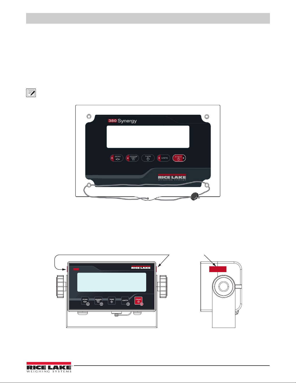
To seal the 380 indicator to restrict access of the CAL jumper, electronics, electrical contacts and Legal for Trade configuration
parameters:
1. Short the CAL jumper to restrict access to setup mode. (Figure 4-1 on page 30)
2. Torque the four front plate screws to 10 in-lb (1.1 N-m).
3. Navigate the lead sealing wire through the lower two fillister head screws on the front plate and the hole at the bottom
center of the front plate, as shown in Figure 4-2.
4. Seal the wire to secure.
NOTE: CAL jumper must be in place to prevent access to Setup mode at startup (Figure 4-1 on page 30).
Figure 4-2. Sealing the 380 Indicator – No Access
4.1.3 Seal the 381
The 381 is sealed with a self-destructive adhesive label (PN 162882) placed over the seam between the two halves of the
indicator. The seal prevents the front and back from being separated and prohibits access to the jumper .
1. Short the CAL jumper to restrict access to setup mode. (Figure 4-1 on page 30)
2. Seal 381 with two self destructive adhesive labels placed over the seam between the two halves of the indicator.
Tamper Proof Label
Figure 4-3. Sealing the 381 Indicator – No Access
© Rice Lake Weighing Systems ● All Rights Reserved 31
Page 32
380/381 Synergy Indicator
AuditSetup Accum Tare time date Vers
Setup
Config Format Calibr Comm Progrm
sFormt DEFLTpformt
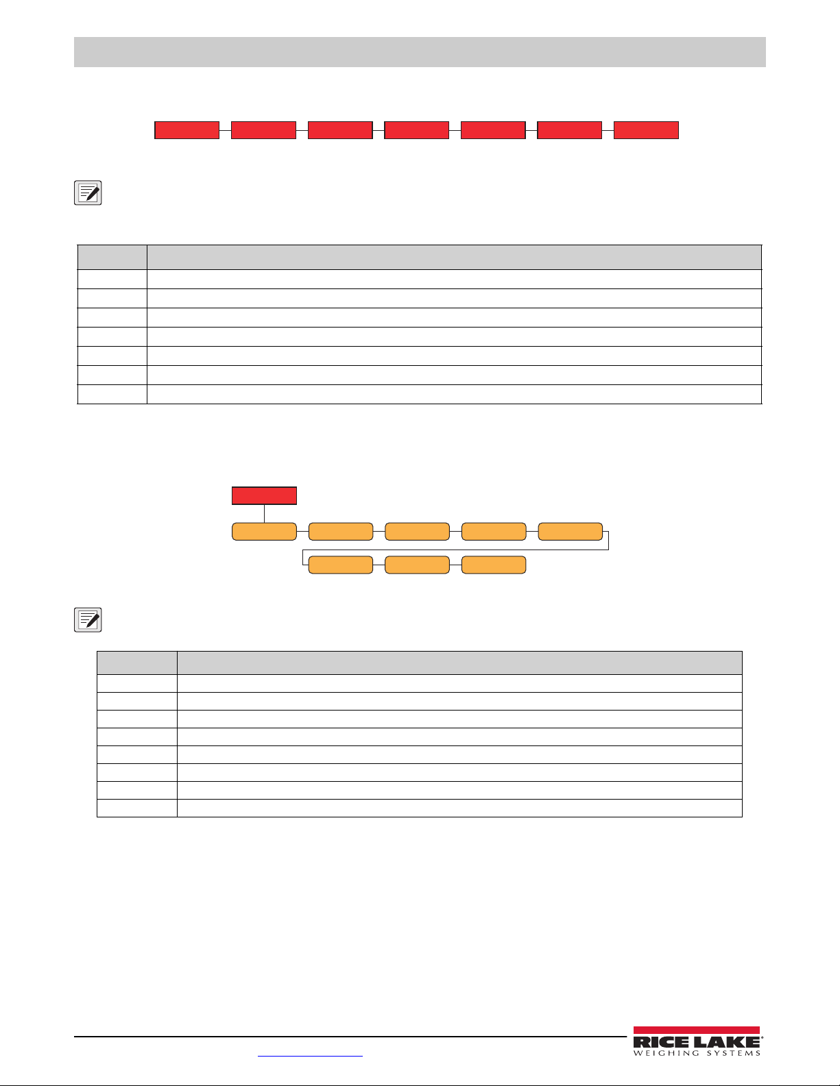
4.2 Main Menu
Figure 4-4. Main Menu
NOTE: * Only visible in setup mode.
NOTE: ** Only visible with RTC option installed.
Parameter Description
Setup
Accum
Tare
time
date
Vers
Audit
Setup – Set configuration parameters for indicator (only visible in setup mode); see Section 4.3
Accumulator – Displays, prints and clears accumulated weight value; see Section 4.4 on page 38
Tare – Displays and clears stored tare value; see Section 4.5 on page 39
Time – Displays the time and allows the time to be edited (24-hour) (Only visible with RTC option installed)
Date – Displays the date and allows the date to be edited (Only visible with RTC option installed)
Version – Displays the installed firmware version number
Audit – Displays the legally relevant firmware version number; see Section 4.6 on page 39
Table 4-1. Main Menu Descriptions
4.3 Setup Menu
Figure 4-5. Setup Menu
NOTE: Setup menu is only visible in setup mode.
Parameter Description
Config
Format
Calibr
Comm
Progrm
Pformt
sformt
deflt
Configuration – See Section 4.3.1 on page 33 for menu structure and parameter descriptions of the Configuration menu
Format – See Section 4.3.2 on page 34 for menu structure and parameter descriptions of the Format menu
Calibration – See Section 4.3.3 on page 34 for menu structure and parameter descriptions of the Calibration menu
Communication – See Section 4.3.4 on page 35 for menu structure and parameter descriptions of the Communication menu
Program – See Section 4.3.5 on page 36 for menu structure and parameter descriptions of the Program menu
Print Format – See Section 4.3.6 on page 37 for menu structure and parameter descriptions of the Print Format menu
Stream Format – See Section 4.3.7 on page 38 for menu structure and parameter descriptions of the Stream Format menu
Default Configuration – Resets settings to indicator default
Table 4-2. Setup Menu Descriptions
32 Visit our website www.RiceLake.com
Page 33
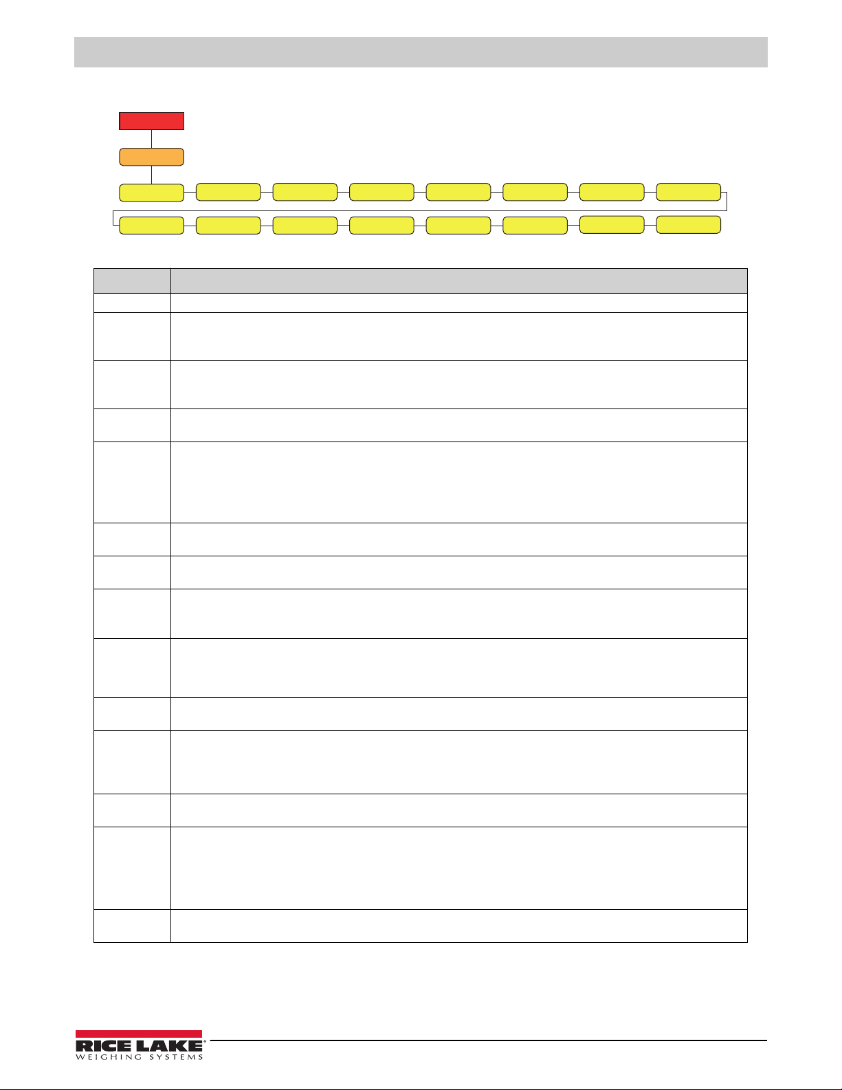
Setup
Config
Capcty
fltchn
digfl1 digfl2
digfl3
dfsens dfthrh
Ztrkbn Zrange Intzro motban ovrloa smprat
rtltrp
tarefn sstime
4.3.1 Setup – Configuration Menu
Figure 4-6. Setup – Configuration Menu
Parameter Description
capcty
Ztrkbn
Zrange
Intzro
Motban
Ovrloa
Smprat
fltchn
digfl1-3
Dfsens
Dfthrh
RTLTRP
Tarefn
Sstime
Capacity – Maximum rated capacity of the scale; Enter value: 0.000001–99999.0, 10000.0 (default)
Zero Track Band – Automatically zeros the scale when within the range specified, as long as the input is within the zrange and
scale standstill; Max legal value depends on local regulations; Specify the zero tracking band in ± display divisions; Enter value:
0.0–100.0, 0.0 (default)
Zero Range – The total amount the scale can be zeroed; Zero range represents a percentage of capacity; The default value of
1.9 represents ±1.9% around the calibrated zero point, for a total range of 3.8%; A value of 0.0 prevents zeroing; Maximum legal
value depends on local regulations; Enter value: 0.0–100.0, 1.9 (default)
Initial Zero Range – When the indicator is turned on and the weight value is between the ± percent range specified of Calibrated
Zero, the indicator automatically zeros off the weight; Enter value: 0.0–100.0, 0.0 (default)
Motion Band – Sets the level, in display divisions, at which scale motion is detected; If motion is not detected for the time defined
by
ss time, the motion annunciator is not displayed; Some operations, including print, tare, and zero, require the scale to be at
standstill; Maximum legal value varies depending on local regulations; If this parameter is set to 0, the motion annunciator is
never lit and operations requiring standstill are performed regardless of scale motion; If 0 is selected,
set to 0; Enter value: 0–100, 1 (default)
Overload – Determines the point at which the display blanks and the overload error message displays (^^^^^^);
Maximum legal value varies depending on local regulations; Settings: FS+2% (default), FS+1D, FS+9D, FS
Sample Rate – Selects measurement rate, in samples per second, of the analog-to-digital converter; Lower sample rate values
provide greater signal noise immunity; Settings: 5HZ, 6HZ, 10HZ, 12HZ, 20HZ, 25HZ (Default), 40HZ, 50HZ, 80HZ, 100HZ
Filter Chain Type – Sets the filter type to be used; Settings:
AVGONLY (default) – Digital Rolling Average Filter (Section 10.5.1 on page 56); Uses DIGFL1-3, DFSENS and DFTHRH
RAW – No filtering
Digital Filters – Sets the digital filtering rate used to reduce the effects of environmental influences from the immediate area of
the scale; Settings indicate the number of A/D conversions per update which are averaged to obtain the displayed reading; a
higher number gives a more accurate display by minimizing the effect of a few noisy readings, but slows down the response time
of the indicator; Settings: 1, 2, 4 (default), 8, 16, 32, 64, 128, 256
Digital Filter Sensitivity – Specifies the number of consecutive A/D readings which fall outside the Filter Threshold before filtering
is suspended; Settings: 2OUT (default), 4OUT, 8OUT, 16OUT, 32OUT, 64OUT, 128OUT
Digital Filter Threshold – Sets a threshold value, in display divisions; when a number of consecutive A/D readings (Digital Filter
Sensitivity) falls outside of this threshold value (when compared to the output of the filter), filtering is suspended and the A/D
value is sent straight through the filter; Filtering is not suspended if the threshold is set to NONE; Settings: NONE (default), 2D,
5D, 10D, 20D, 50D, 100D, 200D, 250D
RattleTrap – Enables RattleTrap filtering; Effective at eliminating vibration effects, environmental influences and mechanical
interference from nearby machinery, may increase response time over standard digital filtering; Settings: OFF (default), ON
Tare Function – Enables or disables push-button and keyed tare; Settings:
BOTH (default) – Both push-button and keyed tare are enabled
NOTARE – No tare allowed (gross mode only)
PBTARE – Push-button tares enabled
KEYED – Keyed tare enabled
Standstill Time – Specifies the length of time the scale must be out of motion, before the scale is considered to be at standstill (in
0.1 sec intervals); Enter value: 0–600, 10 (default)
Table 4-3. Setup – Configuration Menu Descriptions
Configuration
ztrkbnd must also be
© Rice Lake Weighing Systems ● All Rights Reserved 33
Page 34
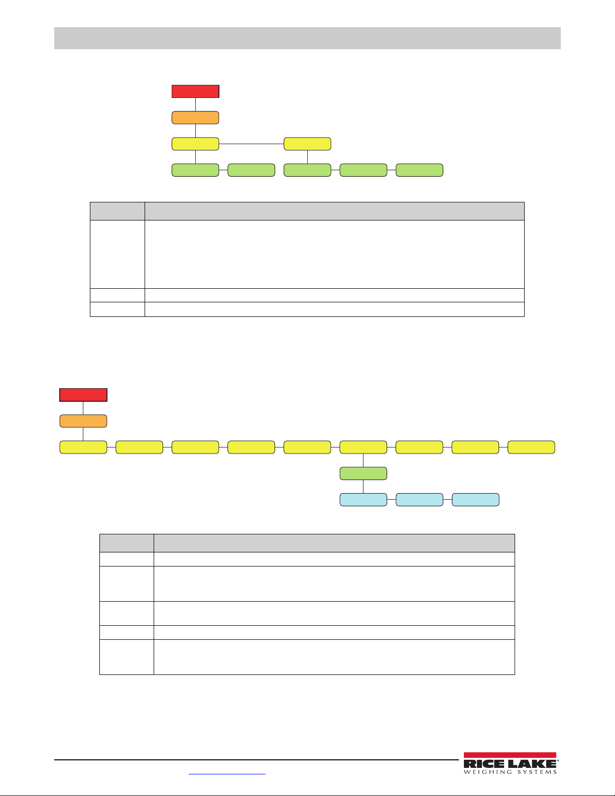
380/381 Synergy Indicator
Setup
Format
FORMAT UNITS
PRIMAR
FORMAT UNITS ENABLE
SECNDR
Setup
Calibr
zrocntWZERO WVAL spncntWSPAN
Point 1-4
WLIN REZERO
Wlinv1-4 wlinc1-4 wlinf1-4
lstzro tmpzro
4.3.2 Setup – Format Menu
Parameter Description
format
Units
ENABLE
Format – Sets the decimal point and the display divisions for the Primary (primar) and Secondary (secndr)
display weight format; For example, select 888.885 if a count by of 0.005 is needed or select 888820 if a count by of
20 is needed (the 8s serve as placeholders and show a breakdown of how digits will display);
Settings: 888881 (Primary default), 888882, 888885, 888810, 888820, 888850, 888100, 888200, 888500, 8.88881,
8.88882, 8.88885, 88.8881, 88.8882, 88.8885, 888.881, 888.882, 888.885, 8888.81, 8888.82, 8888.85, 88888.1,
88888.2, 88888.5 (Secondary default)
Units – Sets the units type; Settings: LB (Primary default), KG (Secondary default), OZ, TN, T, G, NONE
Enabled – Enables UNITS button to toggle between the primary and secondary units; Settings: ON (default), OFF
Figure 4-7. Format – Primary and Secondary Menus
Table 4-4. Format – Primary and Secondary Menu Description
4.3.3 Setup – Calibration Menu
For more information on Calibration procedures, see Section 5.0 on page 40.
Figure 4-8. Setup – Calibration Menu
Parameter Description
wzero
ZROCNT
wval
wspan
SPNCNT
Zero Calibration – Executes the zero calibration process;
Zero Calibration Count – Displays the raw count value at the zero weight; A zero calibration (WZERO)
generates this raw count value; Manually changing this count value changes the zero weight and negates the
zero calibration
Test Weight Value – Sets the weight value for the span calibration;
Enter value: 0.000001–999999.999999, 10000.0 (default)
Span Calibration – Executes the span calibration process;
Span Calibration Count – Displays the raw count value at the span weight; A span calibration (WSPAN)
generates this raw count value; Manually changing this count value changes the span weight and negates the
span calibration
Table 4-5. Setup – Calibration Menu Description
34 Visit our website www.RiceLake.com
Page 35
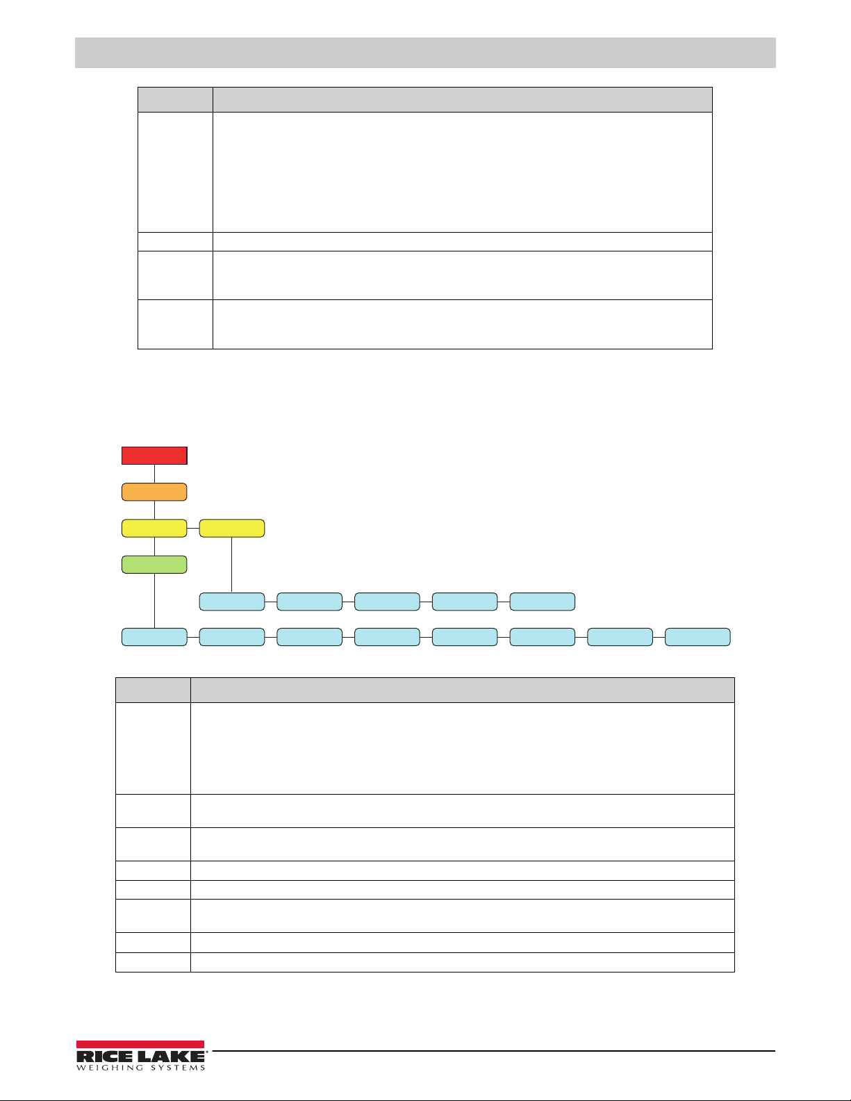
Parameter Description
Setup
Comm
SERIAL
trigge BAUD
RS232
BITS StpBIT TERMIN EOLDLY ECHO ReSPNS
trigge TERMIN EOLDLYECHO ReSPNS
usb
wlin
rezero
LSTZRO
TMPZRO
Linear Calibration – A linear or multi-point calibration is performed by entering up to four additional calibration
points;
WLIN V# – Sets the test weight value for linear calibration point
WLIN C# – Executes the linear calibration process for the point; generates the raw count value (F) for
the test weight value (V)
WLIN F# – Displays the raw count value at the linear point weight; A linear calibration (WLIN C#)
generates this raw count value; Manually changing this count value changes the linear point weight and
negates the linear calibration for the point
Rezero – Removes an offset value from the zero and span calibrations
Last Zero – Takes the last pushbutton zero in the system (from weigh mode) and uses it as the new zero
reference point, after which a new span calibration must be performed; This calibration cannot be performed
when calibrating a scale for the first time
Temporary Zero – Temporarily zeros the displayed weight of a non-empty scale, after a span calibration was
performed; The difference between the temporary zero and the previously calibrated zero value is used as an
offset
Table 4-5. Setup – Calibration Menu Description (Continued)
4.3.4 Setup – Communication Menu
Serial Port supports RS-232 serial communication. USB port Supports USB Virtual communication port.
Configuration
Figure 4-9. Communication – Serial Port Menu
Parameter Description
trigge
baud
bits
STPBIT
termin
eoldly
echo
RESPNS
Trigger – Sets the input trigger type; Settings:
CMD (default) – Command: allows operation of EDP commands and printing
STRIND – Stream Industrial Scale Data: data is updated up to the configured sample rate; allows operation of
EDP commands and printing
STRLFT – Stream Legal for Trade Data: data is updated at the configured display update rate; allows operation of
EDP commands and printing
Baud Rate – Sets the transmission speed for the port (RS-232 only); Settings: 1200, 2400, 4800, 9600 (default), 19200,
38400, 57600, 115200
Data Bits – Sets number of data bits transmitted or received by the port and specifies the parity bit to odd, even or none
(RS-232 only); Settings: 8NONE (default), 7EVEN, 7ODD
Stop Bits – Sets the number of stop bits transmitted or received by the port (RS-232 only); Settings: 1 (default), 2
Outgoing Line Termination – Sets the termination characters for data sent from the port; Settings: CR/LF (default), CR
End of Line Delay – Sets the delay period from when a formatted line is terminated to the beginning of the next
formatted serial output (measured in 0.1 second intervals); Enter value: 0–255, 0 (default)
Echo – Specifies if characters received by the port are echoed back to the sending unit; Settings: ON (default), OFF
Response – Specifies if the port transmits replies to serial commands; Settings: ON (default), OFF
Table 4-6. Communication – Serial Port Menu Description
© Rice Lake Weighing Systems ● All Rights Reserved 35
Page 36
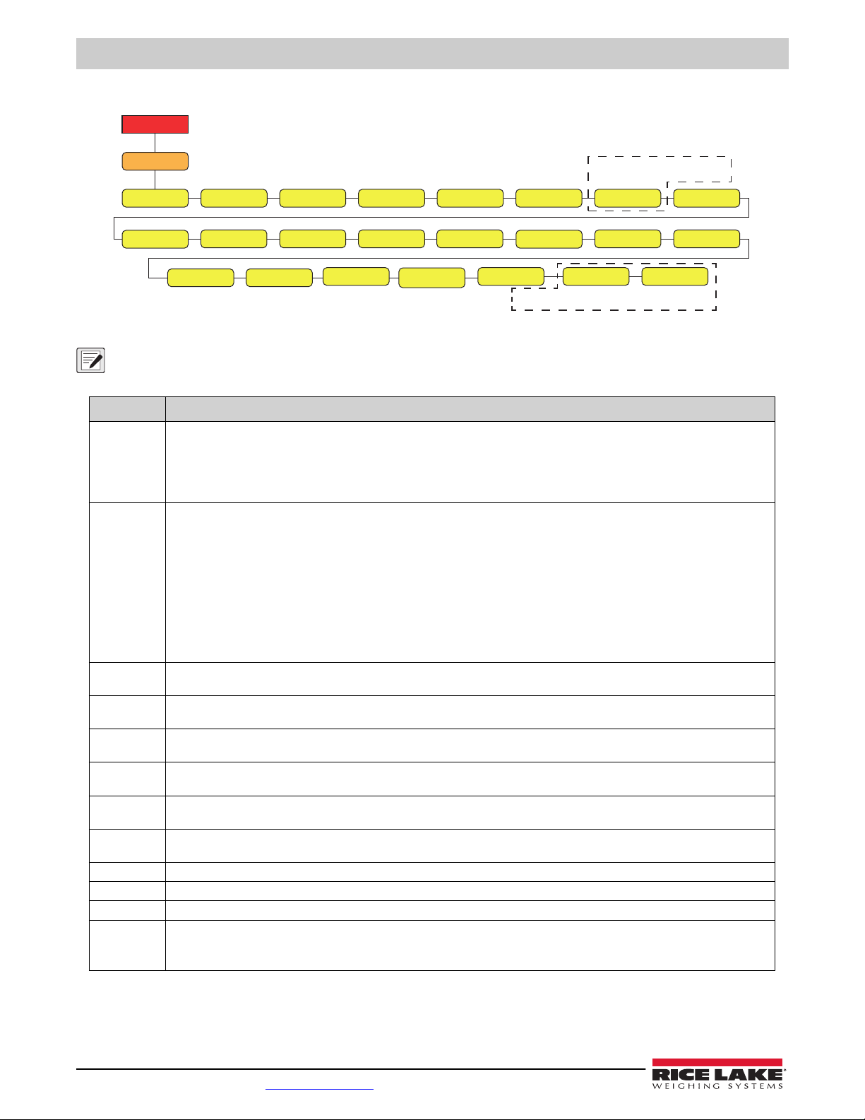
380/381 Synergy Indicator
Setup
Progrm
Pwrupm Regula Consnu Uidconstu
date time
rtzgrd wmtthr
maxwgh kybdlk zeronl
bright
numwgh
Accum
Locale grvorg grvdst
keyhld
autoff
Batery
pwrsav
maxdat
Displays if ACCUM is ON
Displays if
locale is set to Factor
** ** **
4.3.5 Setup – Program Menu
NOTE: ** Only visible with RTC option installed.
Parameter Description
pwrupm
regula
consnu
constu
uid
accum
rtZGrd
WMTTHR
NUMWGH
MAXWGH
MAXDAT
date
Power Up Mode – When the indicator is turned on, it performs a display test, then enters a warm up period; Settings:
GO (default) – Performs display test, then enters weigh mode after brief warm up period
DELAY – Performs display test, then enters a warm up period of 30 seconds
• If no motion is detected during warm up period, indicator enters weigh mode when warm up period ends
• If motion is detected, the 30 second timer is reset and the warm up period is repeated
Regulatory Mode – Specifies the regulatory agency having jurisdiction over the scale site; the value specified for this parameter
affects the function of the front panel tare and zero keys; Settings: NTEP (default), OIML, CANADA, NONE
• OIML, NTEP, and CANADA modes allow a tare to be acquired at a weight greater than zero; NONE allows tares to be
acquired at any weight value
• OIML, NTEP, and CANADA modes allow a tare to be cleared only if the gross weight is at no load; NONE allows tares to be
cleared at any weight value
• NTEP and OIML modes allow a new tare to be acquired even if a tare is already present; In CANADA mode, the previous
tare must be cleared before a new tare can be acquired
• NONE, NTEP and CANADA modes allow the scale to be zeroed in either gross or net mode as long as the current weight is
within the specified ZRANGE; In OIML mode, the scale must be in gross mode before it can be zeroed; pressing the ZERO
key in net mode clears the tare
Consecutive Numbering – Allows sequential numbering for print operations; the value is incremented following each print operation
which includes <CN> in the ticket format; Enter value: 0–999999, 0 (default)
Consecutive Number Startup Value – Specifies the initial consecutive number (CONSNU) value used when the consecutive number
is reset by sending KCLRCN EDP serial command; Enter value: 0–999999, 0 (default)
Unit ID – Specifies the unit identification string with an alphanumeric value;
Enter characters: Up to 8 alphanumeric characters, 1 (default)
Accumulator – Accumulation can be toggled ON/OFF; if ON, accumulation occurs on print operation; if OFF, an accumulation
does not occur; Settings: OFF (default), ON
Return to Zero Grads – When the weight (in display graduations) falls below the value set, the accumulator is rearmed;
Enter Value: 0.0-100.0,
Weighment Threshold – When the weight exceeds the value set, the number of weighments counter is incremented;
Enter value: 0.0–999999.0, 1000.0 (default)
Number of Weighments – Displays the total number of weighments; Read only
Maximum Weighment – Displays the maximum weighment made; Read only
Date/Time of Max Weight – Displays the date the maximum weighment occurred; Read only (only available when RTC is installed)
Date – Allows setting of the date format and date separator character; (only available when RTC is installed)
DATEFMT – Date Format; Settings:
DATESEP – Date Separator; Settings:
0.4
Figure 4-10. Setup – Program Menu
(default)
MMDDYY
(default), DDMMYY, YYMMDD, YYDDMM
SLASH
(default), DASH, SEMI, DOT
Table 4-7. Setup – Program Menu Description
36 Visit our website www.RiceLake.com
Page 37
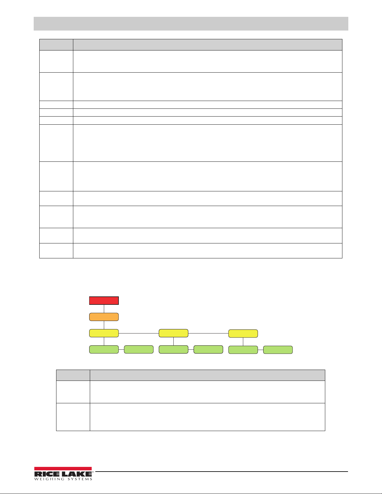
Parameter Description
Setup
Pformt
format dest 1
Nfmt
format dest 1
Gfmt
Format dest 1
Acmfmt
format dest 1
Nfmt
time
keyhld
kybdlk Keyboard Lock – Disables the keyboard except power; settings:
zeronl Zero Only – Disables the keyboard except Zero and Power; settings:
bright Brightness of Back Light; settings:
Batery Battery – Power supply via battery
pwrsav Power Saving mode – Energy saving for battery operation
autoff Auto Off Time – Time (in minutes) at zero weight after which the scale will power off. A setting of 0 will not power off;
locale
grvorg
grvdst
Time – Allows setting of the time format and the separator character; (only available when RTC is installed)
TIMEFMT – Time Format; Settings:
TIMESEP – Time Separator; Settings:
Key Hold – Allows setting of the key hold time and interval
HLDTME – Key hold time (in tenths of a second); 20 equals 2 seconds; Enter value: 10–50, 20 (default)
INTRVL – Key hold time interval; the amount of time between increments during a key hold (in twentieths of a second);
2 equals a tenth of a second (10 increments per second during a key hold); Enter value: 1–100, 2 (default)
NONE – No battery
ALK – Alkaline battery (non-rechargable)
NIMH – Nicken Metal Hydrade
LITHIM – Lithium Ion
NONE
(default)
LOW – Turns off backlight after 30 seconds of no activity; changing weight or a button press will illuminate the backlight
HIGH – Turns off backlight and load cell after 30 seconds at zero weight; any button must be pressed to wake up indicator
Settings: 0 (default) - 60
Location Gravity Compensation – Enables gravity compensation; Settings:
OFF (default) – gravity compensation disabled
FACTOR – uses origin and destination gravity factors to find gravity compensation
Gravity of Origin – Original gravity factor (in m/s2) for gravity compensation; displays when LOCALE parameter is set to FACTOR;
Enter value: 9.00000–9.99999, 9.80665 (default)
Gravity of Destination – Destination gravity factor (in m/s2) for gravity compensation; displays when LOCALE parameter is set to
FACTOR; Enter value: 9.00000–9.99999, 9.80665 (default)
12HOUR
(default), 24HOUR
COLON
(default), COMMA, DOT
LOW
(default), MED, HIGH, OFF
OFF
(Default), ON
OFF
(Default), ON
Table 4-7. Setup – Program Menu Description (Continued)
Configuration
4.3.6 Setup – Print Format Menu
Parameter Description
gfmt
nfmt
Gross Format – Gross demand print format string
FORMAT – Enter characters: Alphanumeric entry up to 300 characters,
DEST 1 – Destination ports; Settings: RS232, USB, NONE
Net Format – Net demand print format string
FORMAT – Enter characters: Alphanumeric entry up to 300 characters,
Gross<g><nl>Tare<sp><t><nl>Net<sp2><n><nl2>
DEST 1 – Destination ports; Settings: RS232, USB, NONE
Figure 4-11. Setup – Print Format Menu
(default)
Table 4-8. Setup – Print Format Menu Description
Gross<g><nl2>
(default)
© Rice Lake Weighing Systems ● All Rights Reserved 37
Page 38
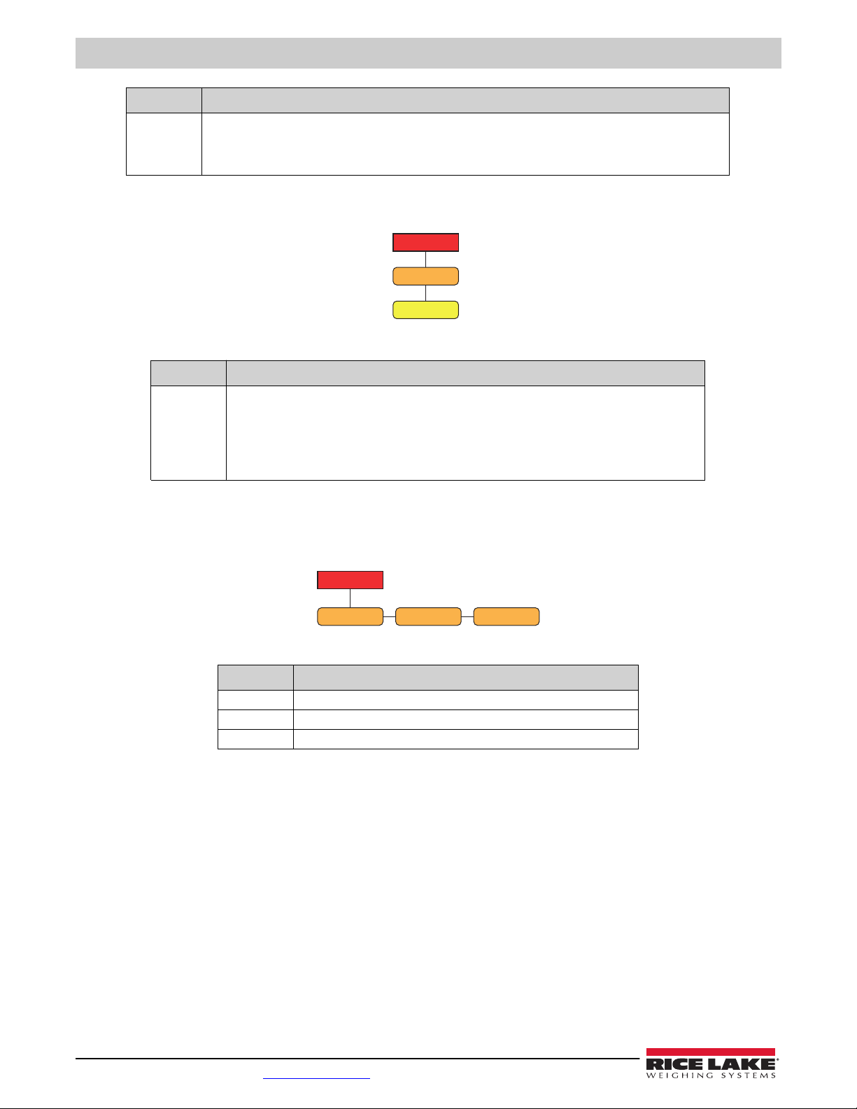
380/381 Synergy Indicator
Setup
sformt
sfmt
ACCUM
dspacm
prtACm CLRACm
Parameter Description
ACMFMT
Accumulator Format – Accumulator print format string
FORMAT – Enter characters: Alphanumeric entry up to 300 characters,
Accum <a><nl>
DEST 1 – Destination ports; Settings: RS232, USB, NONE
(default)
Table 4-8. Setup – Print Format Menu Description
4.3.7 Setup – Stream Format Menu
Parameter Description
SFMT
Stream Format – Specifies the stream format used for streaming output of scale data;
Settings:
RLWS (default) – Rice Lake Weighing Systems stream format; see Section 10.3.1 on page 54
CRDNAL – Cardinal stream format; see Section 10.3.2 on page 54
WTRNIX – Avery Weigh-Tronix stream format; see Section 10.3.3 on page 55
TOLEDO – Mettler Toledo stream format; see Section 10.3.4 on page 55
Table 4-9. Setup – Stream Format Menu Description
Figure 4-12. Setup – Stream Format Menu
4.4 Accumulator Menu
Parameter Description
dspacm
prtacm
clracm
Figure 4-13. Accumulator Menu
Display Accumulator – Displays the accumulator value; Read Only
Print Accumulator – Prints the accumulator value to specified port, if setup
Clear Accumulator – Clears the accumulator value
Table 4-10. Accumulator Menu Description
38 Visit our website www.RiceLake.com
Page 39
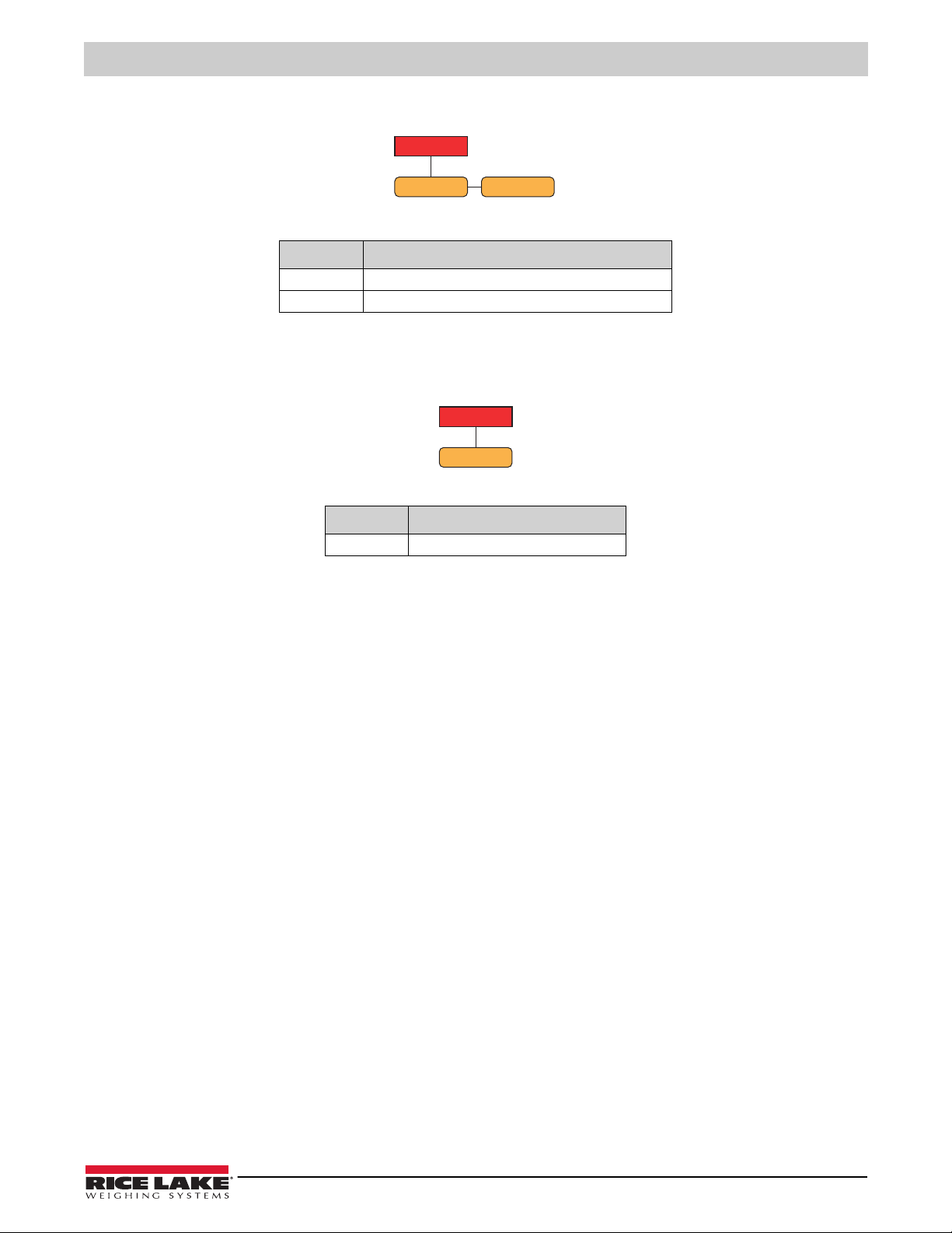
4.5 Tare Menu
TARE
dsptar
CLRTAR
Audit
LRV
4.6 Audit Menu
Figure 4-14. Tare Menu
Parameter Description
dsptar
clrtar
Display Tare – Displays the current tare value; Read Only
Clear Tare – Clears the current tare value
Table 4-11. Tare Menu Description
Figure 4-15. Audit Menu
Configuration
Parameter Description
Lrv
LRV – Legally relevant firmware version
Table 4-12. Audit Menu Description
© Rice Lake Weighing Systems ● All Rights Reserved 39
Page 40
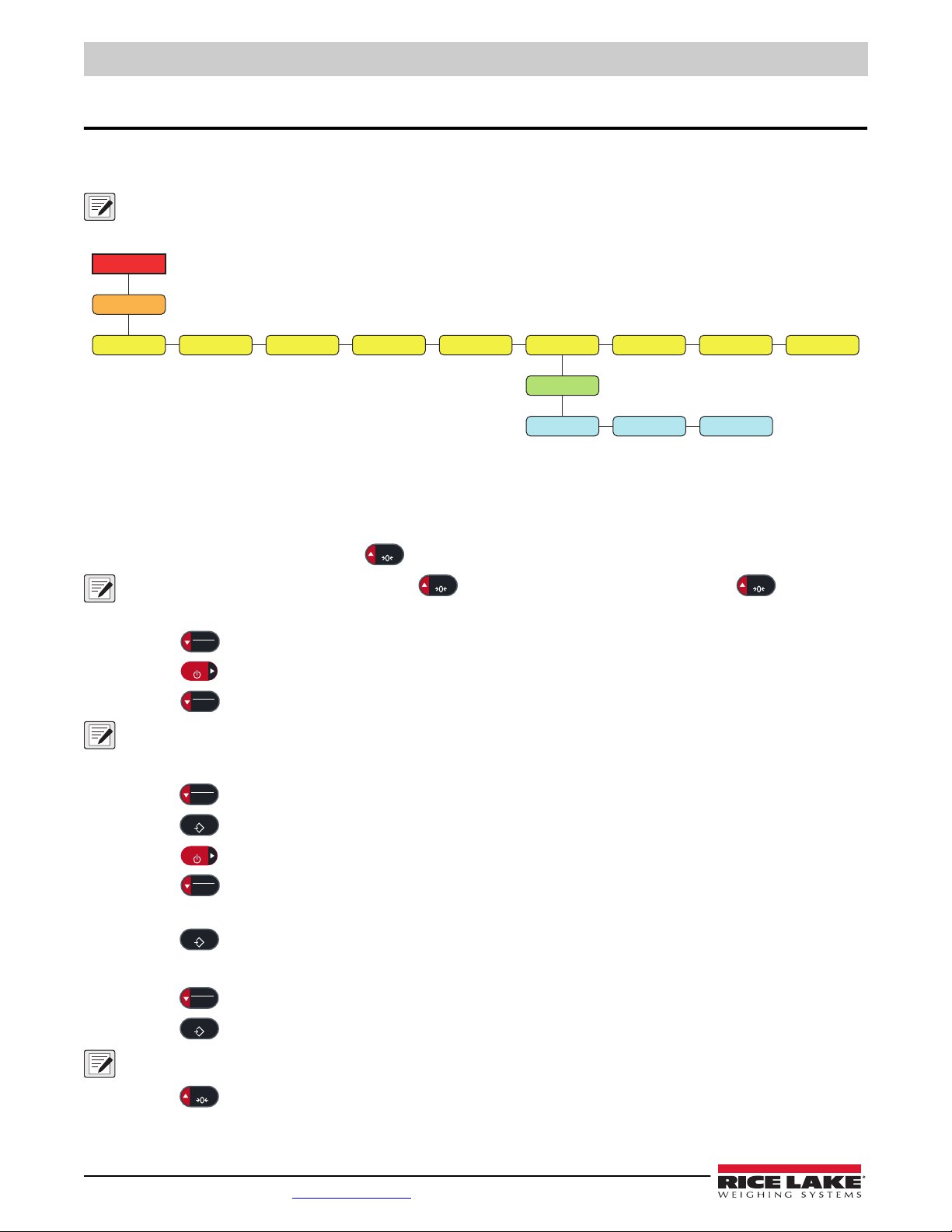
380/381 Synergy Indicator
Setup
Calibr
zrocntWZERO WVAL spncntWSPAN
Point 1-4
WLIN REZERO
Wlin v1-4 wlin c1-4 wlin f1-4
lstzro tmpzro
ZERO
ZERO
ZERO
GROSS
NET
B/N
PRINT
GROSS
NET
B/N
TARE
T
PRINT
GROSS
NET
B/N
TARE
T
TARE
T
ZERO
5.0 Calibration
The 380/381 can be calibrated using the front panel or EDP commands. The following sections describe the procedures
required for these calibration methods.
NOTE: CAL jumper must be removed to perform calibration.
NOTE: The 380/381 requires a WZERO and WSPAN points to be calibrated. The linear calibration points are optional; they
must fall between zero and span, but must not duplicate zero or span.
Figure 5-1. Calibration Menu
5.1 Front Panel Calibration
5.1.1 Span Calibration
Use the following steps to perform a standard span calibration on a connected scale.
1. Access the setup menu by pressing momentarily during power up.
Setup displays.
NOTE: When accessing Setup mode, only press once. Do not press and hold or double press .
NOTE: CAL jumper must be removed to perform calibration (see Section 4.1 on page 30).
2. Press once. config displays
3. Press twice.
4. Press .
NOTE: See Section 5.2 on page 41 if the application requires a rezero, last zero or temporary zero.
Calibr displays.
wzero displays.
5. Ensure there is no weight on the scale.
GROSS
6. Press to perform a zero calibration.
7. Press .
8. Press .
NET
B/N
ZROCNT displays. See Section 4.3.3 on page 34 for more information on ZROCNT.
wval displays.
ok displays.
9. Press . The current test weight value displays.
10. Enter a new value, if necessary. See Section 3.3.1 on page 26 for more information on numeric entry.
11. Press to accept value.
wSpan displays.
12. Place the specified amount of test weight on the scale.
GROSS
13. Press to perform a span calibration.
NET
B/N
ok displays.
14. Press .
SPNCNT displays. See Section 4.3.3 on page 34 for more information on SPNcnt.
NOTE: Span calibration is complete. To continue with a linear calibration, proceed to Section 5.1.2 on page 41 .
15. Press three times to return to weigh mode.
40 Visit our website www.RiceLake.com
Page 41
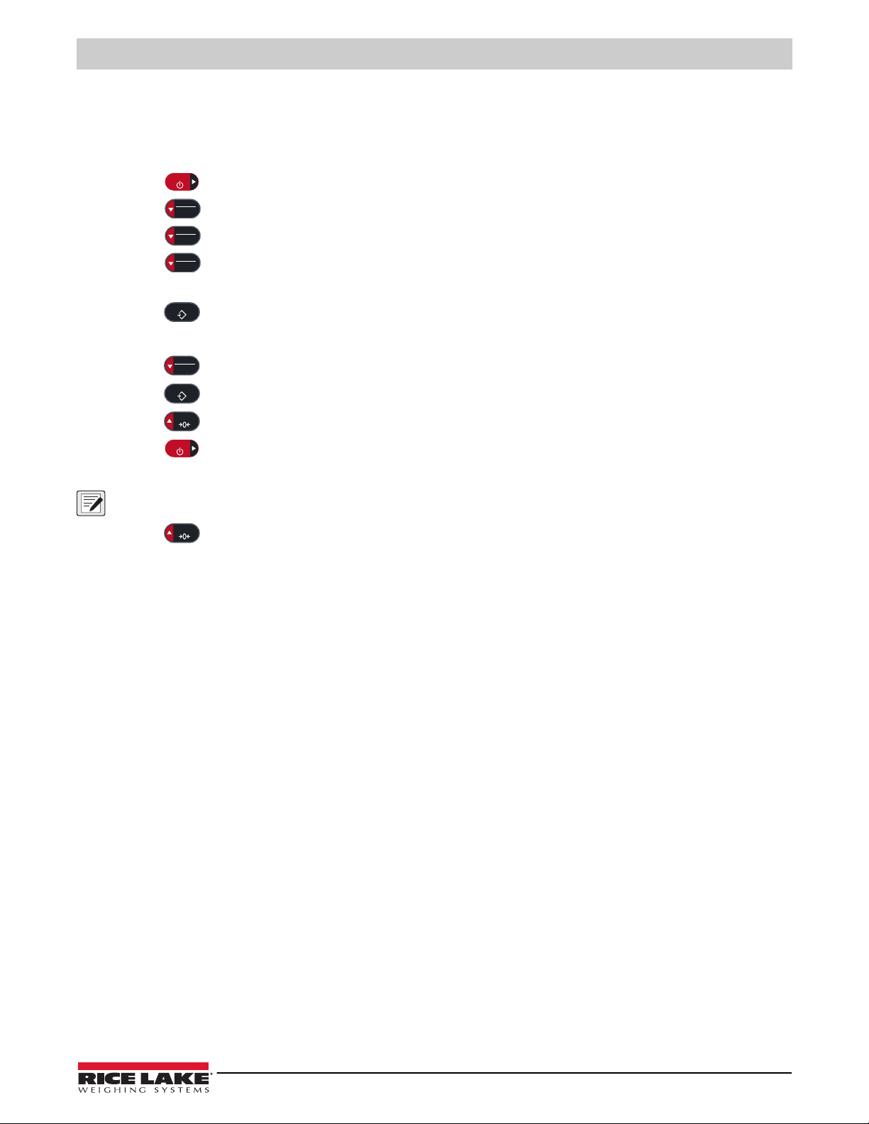
Calibration
PRINT
GROSS
NET
B/N
GROSS
NET
B/N
GROSS
NET
B/N
TARE
T
TARE
T
ZERO
PRINT
ZERO
5.1.2 Linear Calibration
Linear calibration points provide increased scale accuracy by calibrating the indicator at up to four additional points between the
zero and span calibrations.
1. Complete steps 1–14 in Section 5.1.1 on page 40.
2. Press .
3. Press .
4. Press .
wlin displays.
point1 displays.
wlin v1 displays.
5. Press . The current test weight value for point 1 displays.
6. Enter a new value, if necessary. See Section 3.3.1 on page 26 for more information on numeric entry.
7. Press to accept value.
wlin c1 displays.
8. Place the specified amount of test weight on the scale.
GROSS
9. Press to perform a linear point calibration.
10. Press .
11. Press .
12. Press .
NET
B/N
wlin f1 displays. See Section 4.3.3 on page 34 for more information on WLIN F#.
Point1 displays.
Point 2 displays.
ok displays.
13. Repeat previous steps for points 2-4, if necessary.
NOTE: The linear calibration for a point is saved once point is calibrated.
14. Press three times to return to weigh mode.
5.2 Alternative Zero Calibrations
During a calibration, the zero value (wzero) can be replaced with a temporary zero (TMPZRO) or last zero (LSTZRO). A rezero
rezero) can be done after calibration. See below for information on these alternative zeros.
(
5.2.1 Last Zero
This takes the last push-button zero in the system (from weigh mode) and uses it as the new zero reference point, after which a
new span calibration must be performed. This calibration cannot be performed when calibrating a scale for the first time.
A last zero calibration is typically used on truck scales to allow a scale verification to become a calibration without having to
remove the test weights.
5.2.2 Temporary Zero
A temporary zero calibration temporarily zeros the displayed weight of a non-empty scale. After span calibration, the difference
between the temporary zero and the previously calibrated zero value is used as an offset.
A temporary zero calibration is typically used on hopper scales to calibrate the span without losing the original zero calibration.
5.2.3 Rezero
A rezero calibration is needed to remove a calibration offset when hooks or chains are required to suspend the test weights.
Once a span calibration is complete, remove the hooks or chains and the test weights from the scale. With all the weight
removed, a rezero calibration is used to adjust the zero and span calibration values.
© Rice Lake Weighing Systems ● All Rights Reserved 41
Page 42

380/381 Synergy Indicator
5.3 EDP Command Calibration
Use the following instructions to calibrate the 380/381 using EDP commands. For information on the EDP commands of the
380/381, see Section 7.0 on page 44.
NOTE: The indicator must respond with OK after each step or the calibration procedure must be done again.
For commands ending with #s, s is the scale number (1).
1. Enter setup mode (Section 4.1 on page 30).
NOTE: CAL jumper must be removed to perform calibration.
2. For a standard calibration, remove all weight from scale (except hooks or chains which are needed to attach weights).
3. Send the command SC.WZERO#s to perform a standard calibration of the zero point.
• Send SC.TEMPZERO#s to perform a temporary zero calibration
• Send SC.LASTZERO#s to perform a last zero calibration
4. Apply the span calibration weight to the scale.
5. Send the command SC.WVAL#s=xxxxx, where xxxxx is the value of the span calibration weight applied to the scale.
6. Send the command SC.WSPAN#s to calibrate the span point. Continue on to step 7 to calibrate additional
linearization points, or proceed to step 11.
7. Apply weight equal to the first linearization point to the scale.
8. Send the command SC.WLIN.Vn#s=xxxxx, where n is the linearization point number (1-4) and xxxxx is the exact
value of the weight applied.
9. Send the command SC.WLIN.Cn#s to calibrate the linearization point, where n is the linearization point number (1-4).
10. Repeat steps 7–9 for up to four total linearization points.
11. If hooks or chains were used to attach the weights, remove all weight, including the hooks and chains, and send the
command SC.REZERO#s to remove the zero offset.
12. Send the command KSAVEEXIT to return to weigh mode.
42 Visit our website www.RiceLake.com
Page 43
Revolution
6.0 Revolution
The Revolution utility provides a suite of functions used to support configuration, calibration, customization, backing up
configuration settings and updating firmware.
Calibration values and scale configuration can both be saved from and restored to the 380/381 using Revolution.
NOTE: For system requirements visit the Revolution product page on Rice Lake Weighing Systems website.
6.1 Connecting to the Indicator
Connect the PC serial port to com 1 of the 380/381, then click Connect in the toolbar. Revolution attempts to establish
communications to the indicator. If communications settings need to be adjusted, select Options… from the Tools menu.
Downloading to the Indicator
The Send Configuration to Device function in the Revolution Communications menu allows a Revolution configuration file
(with or without scale calibration data) or ticket formats to be downloaded to a connected indicator in setup mode.
The Send Section to Device function on the Communications menu allows the download of only the currently displayed object,
such as a scale configuration.
Because less data is transferred using the Send Section to Device, it is typically faster than a full configuration download, but
there is an increased possibility the download fails due to dependencies on other objects. If the download fails, try performing a
complete download using the Send Configuration to Device function.
Uploading Configuration to Revolution
The Get Configuration from Device function in the Revolution Communications menu allows the existing configuration of a
connected indicator to be saved to a file on the PC. Once saved, the configuration file provides a backup which can be quickly
restored to the indicator if needed. Alternatively, the file can be edited within Revolution and downloaded back to the indicator.
6.2 Saving and Transferring Data
NOTE: Revolution has a module to save and transfer data. It is the preferred method over using ProComm or Hyper
Terminal.
6.2.1 Saving Indicator Data to a Personal Computer
Configuration data can be saved to a computer connected to the selected port. The PC must be running a terminal emulator
such as Tera Term or PuTTY.
When configuring the indicator, ensure the values set for the baud and bits parameters on the serial menu match the baud rate,
bits and parity settings configured for the serial port on the PC.
To save all configuration data, first put the terminal emulator into data capture mode, then
send the DUMPALL command to the indicator. The 380/381 responds by sending all configuration parameters to the PC as
ASCII-formatted text.
6.2.2 Downloading Configuration Data from PC to Indicator
Configuration data saved on a PC or disc can be downloaded from the PC to an indicator. This procedure is useful when a
number of indicators with similar configurations are set up or when an indicator is replaced.
To Send Configuration to the Device, connect the PC to the selected port as described in Section 6.2.1. Place the indicator in
setup mode and use the PC communications software to send the saved configuration data to the indicator. When transfer is
complete, calibrate the indicator as described in Section 5.0 on page 40.
place the indicator in setup mode and
© Rice Lake Weighing Systems ● All Rights Reserved 43
Page 44
380/381 Synergy Indicator
7.0 EDP Commands
The 380/381 indicator can be controlled by a personal computer connected to one of the indicator communication ports. Control
is provided by a set of commands which can simulate front panel key press functions, return and change setup parameters, and
perform reporting functions. The commands provide the capability to print configuration data or to save data to an attached
personal computer. This section describes the EDP command set and procedures for saving and transferring data using the
communication ports. The EDP command set is divided into several groups.
When the indicator processes a command, it either responds with a value (for reporting commands, or when querying
parameter settings), or with the message OK. The OK response verifies the command was received. If the command is
unrecognized, the indicator responds with ?? invalid command. If the command cannot be executed in the current mode, the
indicator responds with ?? invalid mode. If the command is recognized, but the value is out of range or the invalid type, the
indicator responds with ?? followed by the type and the range.
7.1 Key Press Commands
Key press serial commands simulate pressing keys on the front panel of the indicator. These commands can be used in both
setup and weigh mode. Several of the commands serve as pseudo keys, providing functions which are not represented by a
key on the front panel.
For example, to enter a 15 lb tare weight using serial commands:
1. Type K1 and press
2. Type K5 and press
3. Type KTARE and press
Enter (or Return).
Enter.
Enter.
Command Function
KZERO In weigh mode, this command acts like pressing the Zero key
KGROSSNET In weigh mode, this command acts like pressing the Gross/Net key
KGROSS Displays Gross mode (pseudo key)
KNET Displays Net mode (pseudo key)
KTARE In weigh mode, this command acts like pressing the Tare key
KUNITS In weigh mode, this command acts like pressing the Units key
KPRIM Displays primary units (pseudo key)
KSEC Displays secondary units (pseudo key)
KPRINT In weigh mode, this command acts like pressing the Print key
KPRINTACCUM Prints the accumulated weight (pseudo key)
KDISPACCUM Displays the accumulator value (pseudo key)
KDISPTARE Displays the tare value (pseudo key)
KCLR Clears number (pseudo key)
KCLRCN Clears consecutive number (pseudo key)
KCLRTAR Clears the tare from the system (pseudo key)
KLEFT In setup mode, this command moves Left in the menu
KRIGHT In setup mode, this command moves Right in the menu
KUP In setup mode, this command moves Up in the menu
KDOWN In setup mode, this command moves Down in the menu
KEXIT In setup mode, this command exits to weigh mode (pseudo key)
KSAVE In setup mode, save the current configuration (pseudo key)
KSAVEEXIT In setup mode, save the current configuration then exit to normal mode (pseudo key)
KCLRACCUM Clears the accumulator (pseudo key)
Kn This command acts like pressing numbers 0 (zero) through 9 (pseudo key)
KDOT This command acts like pressing the decimal point (.) (pseudo key)
KENTER This command acts like pressing the Enter key (pseudo key)
KLOCK=x In setup mode, this command locks specified front panel key; x = KPRINT, KUNITS, KTARE, KGROSSNET, KZERO
KUNLOCK=x In setup mode, this command unlocks specified front panel key; x = KPRINT, KUNITS, KTARE, KGROSSNET, KZERO
(example: to lock the Zero key, enter KLOCK=KZERO
(example: to unlock the Print key, enter KUNLOCK=KPRINT
Table 7-1. Key Press Commands
44 Visit our website www.RiceLake.com
Page 45
EDP Commands
7.2 Reporting Commands
Reporting commands return specific information to the communications port. The commands listed in Table 7-2 can be used in
either setup mode or weigh mode.
Command Function
DUMPALL Returns a list of all parameter values
AUDIT.LRVERSION Returns the legally relevant firmware version
VERSION Returns the firmware version
BUILD Returns the firmware version and build number
HWSUPPORT Returns the CPU board part number
HARDWARE Returns C1 if the RTC Option is installed, or FF if no option is installed
Table 7-2. Reporting Commands
7.3 Reset Configuration Command
The following command can be used to reset the configuration parameters of the 380/381.
Command Function
RESETCONFIGURATION Restores all configuration parameters to default values (setup mode only)
Table 7-3. Reset Configuration Command
NOTE: All scale calibration settings are lost when the RESETCONFIGURATION command is run.
7.4 Parameter Setting Commands
Parameter setting commands allow the current value for a configuration parameter to be displayed or changed.
Current configuration parameter settings can be displayed in setup mode or weigh mode using the following syntax:
command<ENTER>
Most parameter values can be changed in setup mode only.
Use the following command syntax when changing parameter values: command=value<ENTER>. Use no spaces before or
after the equal (=) sign. If an incorrect command is typed or an invalid value is specified, the indicator returns ?? followed by the
error message.
Example: to set the motion band parameter on Scale #1 to 5 divisions, type the following:
SC.MOTBAND#1=5<ENTER>
To return a list of the available values for parameters, enter the command and equal sign, followed by a question mark
(command=?<ENTER>). The indicator must be in setup mode to use this function.
After changes are made to configuration parameters using EDP commands, use the KSAVE or KSAVEEXIT commands to
commit the changes to memory.
Command Description Values
SC.CAPACITY#n Scale capacity 0.000001–999999.0, 10000.0 (default)
SC.ZTRKBND#n Zero track band (in display divisions) 0.0–100.0, 0.0 (default)
SC.ZRANGE#n Zero range in % of Full Scale (capacity) 0.0–100.0, 1.9 (default)
SC.INITIALZERO#n Initial Zero range in % of full scale 0.0–100.0, 0.0 (default)
SC.MOTBAND#n Motion band (in display divisions) 0–100, 1 (default)
SC.SSTIME#n Standstill time (in 0.1 second intervals; 10 = 1 second) 0–600, 10 (default)
SC.OVERLOAD#n Overload FS+2% (default), FS+1D, FS+9D, FS
SC.MAX_WEIGHT#n Maximum weighment (read only) -999999–999999
SC.NUMWEIGH#n Number of weighments (read only) 0–4294967295
For commands ending with #n, n is the scale number (1)
Table 7-4. Scales Commands
© Rice Lake Weighing Systems ● All Rights Reserved 45
Page 46
380/381 Synergy Indicator
Command Description Values
SC.MAX_DATE#n Date of maximum weighment (read only) Up to 25 alphanumeric characters (Only available if RTC option
SC.WMTTHRH#n Weighment threshold 0.0–999999.0, 1000.0 (default)
SC.DIGFLTR1#n
SC.DIGFLTR2#n
SC.DIGFLTR3#n
SC.DFSENS#n Digital filter cutout sensitivity 2OUT (default), 4OUT, 8OUT, 16OUT, 32OUT, 64OUT, 128OUT
SC.DFTHRH#n Digital filter cutout threshold NONE (default), 2D, 5D, 10D, 20D, 50D, 100D, 200D, 250D
SC.SMPRAT#n Scale A/D sample rate 5HZ, 6HZ, 10HZ, 12HZ, 20HZ, 25HZ (default), 40HZ, 50HZ,
SC.PWRUPMD#n Power up mode GO (default), DELAY
SC.TAREFN#n Tare function BOTH (default), KEYED, NOTARE, PBTARE
SC.PRI.FMT#n Primary units format (decimal point and
SC.PRI.UNITS#n Primary units LB (default), KG, OZ, TN, T, G, NONE
SC.SEC.FMT#n Secondary units format (decimal point and
SC.SEC.UNITS#n Secondary units LB, KG (default), OZ, TN, T, G, NONE
SC.SEC.ENABLED#n Enable the Secondary Units ON (default), OFF
SC.FILTERCHAIN#n Defines what filter to use AVGONLY (default), RAW
SC.RTZGRAD#n Number of graduations from the zero base at which the
SC.ACCUM#n Accumulator enable OFF (default), ON
SC.WZERO#n Perform zero calibration —
SC.TEMPZERO#n Perform temporary zero calibration —
SC.LASTZERO#n Perform last zero calibration —
SC.WVAL#n Test weight value 0.000001–999999.999999, 10000.0 (default)
SC.WSPAN#n Perform span calibration —
SC.WLIN.F1#n–
SC.WLIN.F4#n
SC.WLIN.V1#n–
SC.WLIN.V4#n
SC.WLIN.C1#n–
SC.WLIN.C4#n
SC.LC.CD#n Zero (deadload) coefficient raw count value 0–16777215, 8386509 (default)
SC.LC.CW#n Span coefficient raw count value 0–16777215, 2186044 (default)
SC.LC.CZ#n Temporary zero raw count value 0–16777215, 2186044 (default)
SC.REZERO#n Perform the Rezero calibration function —
For commands ending with #n, n is the scale number (1)
Number of A/D samples averaged for the individual
stages (1-3) of the three stage digital filter
display divisions)
display divisions)
accumulator re-arms itself
Actual raw count value for linearization points 1–4 0–16777215, 0 (default)
Test weight value for linearization points 1–4 (A setting
of 0 indicates the linearization point is not used)
Perform linearization calibration on points 1–4 —
is installed)
1, 2, 4 (default), 8, 16, 32, 64, 128, 256
80HZ, 100HZ
888100, 888200, 888500, 888810, 888820, 888850,
888881 (default), 888882, 888885, 88888.1, 88888.2, 88888.5,
8888.81, 8888.82, 8888.85, 888.881, 888.882, 888.885,
88.8881, 88.8882, 88.8885, 8.88881, 8.88882, 8.88885
888100, 888200, 888500, 888810, 888820, 888850, 888881,
888882, 888885, 88888.1, 88888.2, 88888.5 (default), 8888.81,
8888.82, 8888.85, 888.881, 888.882, 888.885, 88.8881,
88.8882, 88.8885, 8.88881, 8.88882, 8.88885
0.0–100.0, 0.4 (default)
0.000001–999999.999999, 0.0 (default)
Table 7-4. Scales Commands (Continued)
7.5 USB Setting Commands
Command Description Values
USB.TRIGGER USB serial function CMD (default), STRIND, STRLFT
USB.LINETERM USB line termination characters CR/LF (default), CR
USB.ECHO USB echo ON, OFF (default)
USB.RESPONSE USB response ON (default), OFF
USB.EOLDLY USB end-of-line delay 0–255 (0.1-second intervals), 0 (default)
Table 7-5. USB Port Commands
46 Visit our website www.RiceLake.com
Page 47
7.6 EDP Setting Commands
Command Description Values
EDP.TRIGGER#p Port serial function CMD (default), STRIND, STRLFT
EDP.BAUD#p Port baud rate 1200, 2400, 4800, 9600 (default), 19200, 38400, 57600, 115200
EDP.BITS#p Port data bits/parity 8NONE (default), 7EVEN, 7ODD
EDP.TERMIN#p Port line termination characters CR/LF (default), CR
EDP.STOPBITS#p Port stop bits 1 (default), 2
EDP.ECHO#p Port echo ON (default), OFF
EDP.RESPONSE#p Port response ON (default), OFF
EDP.EOLDLY#p Port end-of-line delay 0–255 (0.1-second intervals), 0 (default)
For commands ending with #p, p is the port number (1); This is a 1-port device
Table 7-6. Serial Port Commands
7.7 Stream Setting Commands
Command Description Values
STRM.FORMAT#n Stream format RLWS (default), CRDNAL, WTRNIX, TOLEDO
For commands ending with #n, n is the stream format number (1)
Table 7-7. Stream Formatting Commands
EDP Commands
7.8 Feature Commands
Command Description Values
DATEFMT Date format ** MMDDYY (default), DDMMYY, YYMMDD, YYDDMM
DATESEP Date separator ** SLASH (default), DASH, SEMI, DOT
TIMEFMT Time format ** 12HOUR (default), 24HOUR
TIMESEP Time separator ** COLON (default), COMMA, DOT
BRIGHTNESS Brightness of the backlight OFF, LOW (default), MED, HIGH
AUTOFFTIME Auto off time 0-60 seconds, 0=Always On (default)
BATTERYINSTALLED Power source NONE, ALK (default)
POWERSAVEMODE Power save mode NONE (default), LOW, HIGH
CONSNUM Consecutive numbering 0–999999, 0 (default)
CONSTUP Consecutive number start-up value 0–999999, 0 (default)
UID ID of the indicator Up to 8 alphanumeric characters, 1 (default)
KYBDLK Keyboard lock (disable keypad except power) OFF (default), ON
ZERONLY Disable all keys except ZERO and power OFF (default), ON
KHOLDTIME Key hold time (in tenths of a second); 20 equals 2 seconds 10–50, 20 (default)
KHOLDINTERVAL Key hold time interval; the amount of time between increments
LOCALE Enable gravity compensation OFF (default), FACTOR
GRAV.LOC
DEST.GRAV.LOC
BATTERYINSTALLED Installed battery NONE, ALK, NIMH, LitHiM
** Date/time functions only available with RTC option
during a key hold (in twentieths of a second); 2 equals a tenth
of a second (10 increments per second during a key hold)
2
Origin gravity factor (in m/s
Destination gravity factor (in m/s
) for gravity compensation
2
) for gravity compensation
Table 7-8. Feature Commands
1–100, 2 (default)
9.00000–9.99999, 9.80665 (default)
9.00000–9.99999, 9.80665 (default)
© Rice Lake Weighing Systems ● All Rights Reserved 47
Page 48
380/381 Synergy Indicator
7.9 Print Format Commands
Command Description Values
GFMT
GFMT.PORT
NFMT
NFMT.PORT
ACCFMT
ACC.PORT
Gross demand print format string For the .PORT commands, specify the port name as RS232-1, USB, NONE
Net demand print format string
Accumulator print format string
Example: To send the Gross format out RS-232, send:
GFMT.PORT=RS232-1
See Section 8.0 on page 49 for information about demand print format strings
Table 7-9. Print Format Commands
7.10 Weigh Mode Commands
These commands function in the weigh mode. Non weight related commands work in setup mode.
Command Description Values
P Returns what the indicator is currently displaying -ZZ Returns what the indicator is currently displaying;
as well as an additional number representing the
currently displayed annunciators
CONSNUM Returns current consecutive number value 0–999999, 0 (default)
UID Sets or returns the unit ID Up to 8 alphanumeric characters, 1 (default)
SD Sets or returns the current system date ** MMDDYY, DDMMYY, YYMMDD, or YYDDMM. Enter six-digit date using the
ST Sets or returns the current system time ** HHMM (enter using 24-hour format)
STS Sets or returns the current system time with sec-
onds **
RS Resets system Soft reset; Used to perform a power up reset of the indicator without resetting the
SX Starts all serial data streams -EX Stops all serial data streams -SX#p Starts serial data stream for port p OK or ??
EX#p Stops serial data stream for port p
SF#n Returns a single stream frame from scale n using
the standard Rice Lake format.
XA#n Returns the accumulator value in displayed units nnnnnnnnnn UU
XAP#n Returns the accumulator value in primary units
XAS#n Returns the accumulator value in secondary units
XG#n Returns the gross weight in displayed units nnnnnnnnnn UU
XGP#n Returns the gross weight in primary units
XGS#n Returns the gross weight in secondary units
XN#n Returns the net weight in displayed units nnnnnnnnnn UU
XNP#n Returns the net weight in primary units
XNS#n Returns the net weight in secondary units
XT#n Returns the tare weight in displayed units nnnnnnnnnn UU
XTP#n Returns the tare weight in primary units
XTS#n Returns the tare weight in secondary units
For commands ending with #n, n is the scale number (1); For commands ending with #p, p is the port number (1)
** Date/time functions only available with RTC option
Table 7-10. Weigh Mode Commands
See Section 10.2 on page 53
year-month-day order specified for the DATEFMT parameter, using only the last two
digits of the year; The current system date is returned by only sending SD
The current system time is returned by only sending ST
HHMMSS (enter using 24-hour format)
The current system time is returned by only sending STS
configuration to the factory defaults
An EX command sent while in setup mode does not take effect until the indicator is
returned to weigh mode
--
48 Visit our website www.RiceLake.com
Page 49
Print Formatting
8.0 Print Formatting
The 380/381 provides three print formats, GFMT, NFMT and ACCFMT, which determine the format of the printed output when
Print key is pressed. If a tare has been entered or acquired, NFMT is used; otherwise, GFMT is used.
the
Each print format can be customized to include information, such as company name and address, on printed tickets. The print
format is programmed using a combination of print formatting tokens (as in Table 8-1) and ASCII characters. The configuration
may contain a total of up to 300 characters. The output sent to the printer may contain up to 400 characters. Use the print
format menu through front panel of the indicator or revolution to customize the print format.
NOTE: Press the down arrow to view the ASCII character decimal value on the second menu level.
NOTE: See Section 10.6 on page 58 to view the ASCII character chart.
8.1 Print Formatting Tokens
Table 8-1 lists tokens which can be used to configure the print formats. Tokens included in the format strings must be enclosed
between < and > delimiters. Characters outside of the delimiters are printed as text on the ticket. Text characters can include
ASCII characters which can be printed by the output device.
Token Description
<G> Gross weight in displayed units
<G/P> Gross weight in Primary units
<G/S> Gross weight in Secondary units
<N> Net weight in displayed units
<N/P> Net weight in Primary units
<N/S> Net weight in Secondary units
<T> Tare weight in displayed units
<T/P> Tare weight in Primary units
<T/S> Tare weight in Secondary units
<A> Accumulated weight in displayed units
<AC> Number of accumulator events (5 digit counter) **
<AD> Date of last accumulator event ** ***
<AT> Time of last accumulator event ** ***
<UID> Unit ID number (up to 8 characters)
<CN> Consecutive number (up to 8 numeric digits)
<NLnn> New line (nn = number of termination (<CR/LF> or <CR>) characters)*
<SPnn> Space (nn = number of spaces)*
<SU> Toggle weight data format (formatted/unformatted)
<TI> Time ***
<DA> Date (prints 4 digit year) ***
<TD> Time & Date ***
<nnn> ASCII character (nnn=decimal value of ASCII character); used for inserting control characters
(STX, for example) in the print stream
Gross, net, and tare weights are 9 digits in length, including sign (10 digits with decimal point) followed by a
space and a two-digit units identifier. Total field length with units identifier is 12 (or 13) characters.
For tare weights only, PT is added to the output if the Tare is a Keyed tare, adding 3 additional characters to the
total field length.
UID and consecutive number (CN) fields are up to 8 characters in length.
* If nn is not specified, 1 is assumed. Value must be in the range 1–99.
** Accumulator events print 0 unless the accumulator is turned on
*** Date and time function only available with RTC option installed
Table 8-1. Print Format Tokens
© Rice Lake Weighing Systems ● All Rights Reserved 49
Page 50
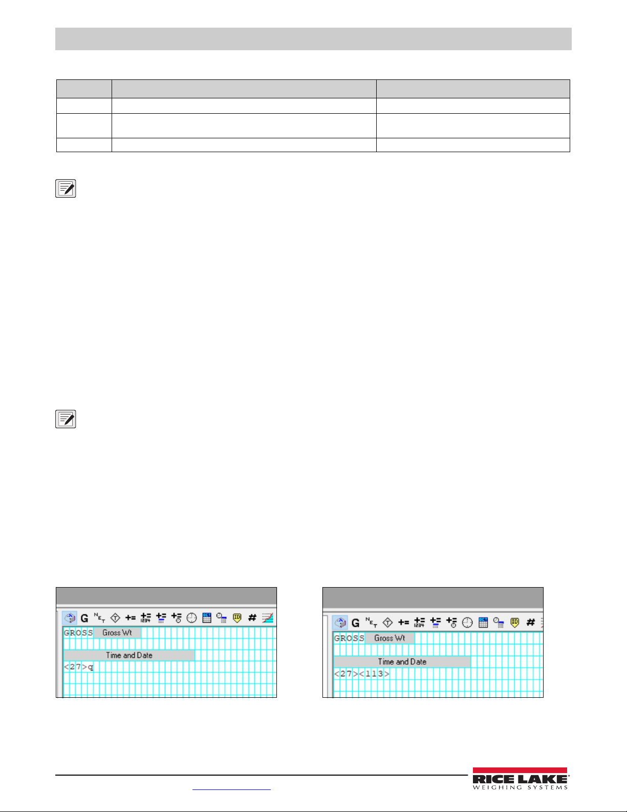
380/381 Synergy Indicator
Table 8-2 lists the default 380/381 print formats:
Format Default Format String When Used
GFMT GROSS<G><NL2>
NFMT GROSS<G><NL>TARE<SP><T><NL>NET<SP2><N>
<NL2>
ACCFMT ACCUM <A> Accumulator demand print format string
Table 8-2. Default Print Formats
NOTE: The <G/P>, <N/P> and <T/P> tokens (Table 8-1 on page 49) print the gross, net and tare weights in primary units.
NOTE: The <G/S>, <N/S> and <T/S> tokens (Table 8-1 on page 49) print the gross, net and tare weights in secondary units.
NOTE: The 400 character limit of each print format string includes the output field length of the print formatting tokens, not
the token length. For example, if the indicator is configured to display a decimal point, the <G> token generates an output
field of 13 characters: the 10 character weight value (including decimal point), one space, and a two-digit units identifier.
Configured print format string including tokens is limited to 300 characters.
NOTE: PT (preset tare) is added to the tare weight if tare was keyed in.
Weigh mode
Weigh mode
– no tare in system
– tare in system
8.2 Customizing Print Formats
The GFMT, NFMT and ACCFMT formats can be customized using the print format menu (PForMT) via the front panel. See
Section 4.3.6 on page 37 for the print format menu structure. To access the print format menu the indicator must be in setup
mode (Section 1.3 on page 8).
Using the Front Panel
Use the print format menu to customize the print formats and to edit the print format strings by changing the ASCII characters in
the format string. See Section 3.3.2 on page 26 for the alphanumeric entry procedure to edit the print format string.
NOTE: Some characters cannot be displayed on the 380/381 front panel, see the ASCII character chart in Section 10.6 on
page 58 for available characters. The 380/381 can send or receive many ASCII characters; the character printed depends on
the particular ASCII character set implemented for the receiving device.
8.3 Non-Human Readable Characters
ASCII characters 0 through 31 are non-human readable characters. Since these characters are not visible, they do not appear as selectable
options in a 380/381 print format. To include a special character in a print format, the decimal equivalent needs to be used. For example, the
special character Esc would be <27> or 60, 50, 55, 62 (less the commas).
Examples of a print release command for a TMU295 in the GROSS format:
Print Format:
GROSS<G><NL2><TD><NL><27>q
In Revolution:
Print Format:
GROSS<G><NL2><TD><NL><27><113>
In Revolution:
50 Visit our website www.RiceLake.com
Page 51
Maintenance
9.0 Maintenance
The maintenance information in this manual is designed to cover aspects of maintaining and troubleshooting the 380/381
indicator. Contact the local Rice Lake Weighing Systems dealer if a problem requires technical assistance.
NOTE: Have the scale or indicator model number and serial number available when calling for assistance.
9.1 Maintenance Checkpoints
The scale must be checked frequently to determine when a calibration is required. It is recommended a zero calibration be
checked every other day and a calibration checked every week for several months after installation. Observe the results and
change the period between calibration checks, depending upon the accuracy desired.
NOTE: Establish a routine inspection procedure. Report changes in the scale function to the individual or department
responsible for the scale’s performance.
9.2 Field Wiring
If a problem with the wiring is suspected, check the electrical portion of the scale.
• Check for proper interconnections between the components of the system
• Check wiring meets all specifications in the installation drawings
• Check all wiring and connections for continuity, shorts and grounds using an ohmmeter with the scale off
• Check for loose connections, poor solder joints, shorted or broken wires and unspecified grounds in wiring; these issues
cause erratic readings and shifts in weight readings
• Check all cable shields to ensure grounding is made at only the locations specified in the installation drawings
9.3 Troubleshooting
Table 9-1 lists general troubleshooting tips for hardware and software error conditions
Symptom Possible Cause Remedy
380/381 does not power up Discharged Batteries Test batteries,
• 380-2D
– Test each cell; If individual cells are < 1 VDC, or the total is < 4 VDC – replace all batteries
• 381-2D-AA
– Test each cell; If individual cells are < 1 VDC, or the total is < 4 VDC – replace all batteries
• 381-2D-NiMh
– If the battery measures < 5 VDC, plug in the indicator to charge
– If Battery depletes rapidly, replace the battery pack.
Bad power supply Check power supply;
• Check presence of AC power – breaker tripped or unit unplugged
• 380-2D and 381-2D-AA – power supply outputs around 12 VDC – replace if not
• 381-2D-NiMH – charger supplies variable voltage; Voltage starts as 5.8 VDC and increases to
over 7 VDC. If this does not happen, charger may need to be replaced
In Bootmode Remove and reapply power or fix cause for firmware update failure and repeat update
vvvvvvv
or
vvvvvvv
Serial port not responding Configuration error Ensure port TRIGGER parameter is set to CMD for command input; Software to check syntax
A/D scale out of range Scale operation
Over or under range
scale condition
Load cell connection
Bad load cell
Check scale; For out-of -range conditions in total scale display, check all scale inputs for positive weight
values
Check source scale for proper mechanical operation
Check load cell and cable connection
Check 380/381 operation with load cell simulator
Check status of sense settings
Table 9-1. Basic Troubleshooting
© Rice Lake Weighing Systems ● All Rights Reserved 51
Page 52
380/381 Synergy Indicator
ZERO
9.4 Board Replacement
IMPORTANT: Use anti-static protection for grounding and to protect components from electrostatic discharge (ESD) when
working inside the 380/381 enclosure. Procedures requiring work inside the 380/381 must be performed by qualified service
personnel only.
To replace a 380/381 board, use the following procedure:
1. Remove the batteries or disconnect the external power to the indicator if being used.
CAUTION: Disconnecting the external power at the 380/381 will activate the batteries if they are installed.
2. Remove front plate as described in Section 2.5 on page 11.
3. Label connections for re-installation to board.
4. Disconnect all connections from the board.
5. Remove the three corner nuts and one standoff securing the board and remove the board.
6. Place the replacement board onto the front plate and secure with previously removed nuts and standoff.
7. Reconnect all connections to the board. See Figure 2-11 on page 16 for details on the board connectors.
8. Replace the front plate and secure the screws as in Section 2.10 on page 19.
IMPORTANT: Always verify indicator has been returned back to a safe state with the proper installation of all connections
and a complete functions test before reinstalling the front plate and returning the indicator back to service.
9.5 Updating Firmware
There are two ways to update the firmware; By using the Revolution software and a .bef file or by using a direct connection to
the PC and an .exe file.
NOTE: Use Revolution version 3.33 or later.
NOTE: CAL jumper must be removed to update firmware. If CAL jumper is not removed, update will fail and message
“The CPU board is in LEGAL state!” will display.
NOTE: Updating firmware defaults configuration settings.
9.5.1 With Revolution
Revolution is used to update the firmware of the 380/381 indicator. The link to begin this process is available on the Revolution
home screen. Connect to the indicator as in Section 6.1 on page 43.
9.5.2 Without Revolution
NOTE: All versions of the Synergy indicators use the same 380* firmware.
1. Download the new firmware from www.ricelake.com/380. Package will include two files with filenames that begin with
‘380_PN202264_Vx.xx’.
2. Connect indicator to computer via one of the following:
• Micro USB (Figure 2-11 on page 16)
• Serial connecter CN10 on the 380 (Section 2.8.2 on page 16)
• External RJ11/12 on the 381
3. Turn off indicator.
4. Press and hold while powering on the indicator. The display will remain off, but if indicator is connected to the
PC via the USB, the PC will emit a sound indicating a USB connection to the PC is configured.
5. Run the * .exe file.
6. Select the COM port on the PC that is associated with the USB or RS-232 port.
7. Select Program and wait for
Firmware Updated Successfully to display. When update process is complete, the 380/381
indicator turns off.
52 Visit our website www.RiceLake.com
Page 53
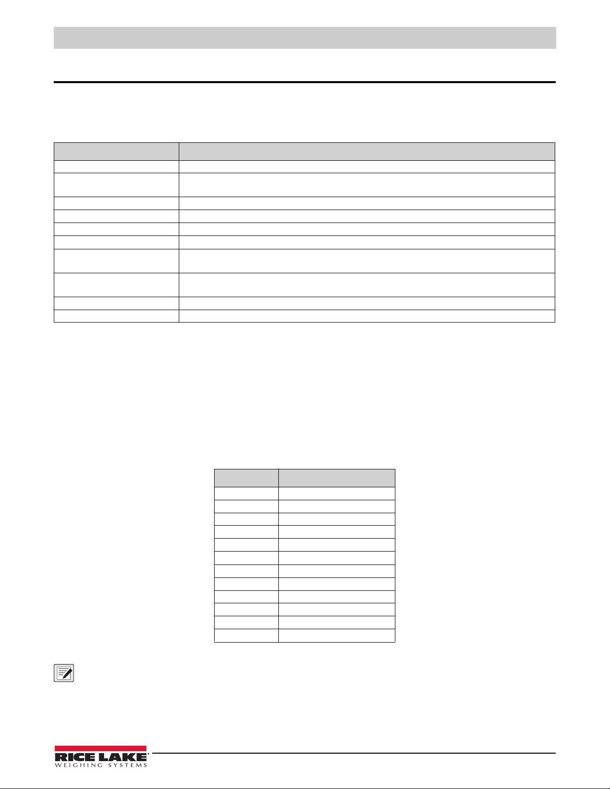
Appendix
10.0 Appendix
10.1 Error Messages
The 380/381 provides a number of front panel error messages to assist in problem diagnosis. Table 10-1 lists these messages
and their meanings.
Error Message Description
------- Overflow error – Weight value too large to be displayed
vvvvvvv
vvvvvvv Gross < underload limit – Gross value exceeds underload limit
tare in motion not allowed Scrolls across display when attempting to perform a tare while weight is in motion, if in motion tares are not allowed
negative tare not allowed Scrolls across display when attempting to perform a negative tare, if a negative tare is not allowed
keyed tare not allowed Scrolls across display when attempting to perform a keyed tare, if a keyed tare is not allowed
tare larger than capacity
not allowed
tare already in system Scrolls across display when attempting to perform a tare if a tare is already in the system, if tare is not configured to
initial zero failed Scrolls across display when an attempt to perform an initial zero fails, only possible at startup
please wait Scrolls across display when calibrating
Gross > overload limit –
be caused by input signal > 45 mV or common mode voltage > 950 mV
Scrolls across display when attempting to perform a tare larger than capacity, if it is not allowed
replace or remove
Gross value exceeds overload limit; Check configuration or signal input level; Overload can
Table 10-1. Error Messages
10.2 ZZ EDP Command
The ZZEDP command can be used to remotely query whatever is being displayed on the LCD Display, along with a decimal
number representing the annunciators currently lit. The format on the returned value is WWWWWW UU NNN in weight display
modes, and VVVVVV NNN in non-weight display modes. NNN is a number between 0 and 4095, and is the sum of values
representing the different annunciators (Table 10-2).
Example:
If the annunciator status value returned for the ZZ command is 0145, the gross, standstill and lb annunciators are on.
The number 0145 represents the sum of the values for the gross mode annunciator (16), the standstill annunciator
(128) and the lb annunciator (1).
Decimal Value Annunciator
1 lb units
2 kg units
4 Tare entered
8 Keyed tare entered
16 Gross
32 Net
64 Center of zero
128 Standstill
256 oz units
512 tn units
1024 t units
2048 g units
Table 10-2. Status Codes Returned on the ZZ Command
NOTE: Standstill bit is set when the In-Motion annunciator is NOT lit.
© Rice Lake Weighing Systems ● All Rights Reserved 53
Page 54
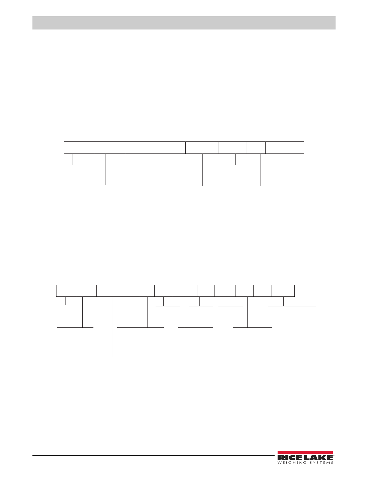
380/381 Synergy Indicator
<STX> <POL> <wwwwwww> <UNIT> <G/N> <S> <TERM>
ASCII 002
Polarity:
<space> = Positive
<–> = Negative
Weight: 7 digits, right-justied, dummy
zeroes, decimal point with no leading
zeroes except for leading zero immediately
preceding the decimal point. Leading
zeroes transmitted as spaces.
L = pounds
K = kilograms
T = tons
G = grams
O = ounces
G = Gross
N = Net
Status:
<space> = valid
I = Invalid
M = Motion
O = Over/under range
Z = COZ
<CR> <LF>
or <CR>
Carriage
Return
Polarity:
<+> for positive
"–" for negative
Six digits, right justified, floating decimal
(follows weight if not embeded),
leading zeroes are present.
g for Gross
n for Net
Hex value of <03>
is entered in string
lb = pound
kg = kilogram
g = gram
tn = ton (short)
t = ton (metric)
oz = ounce
<space> = none
Space
Character
<CR> <POL> <wwwwww> <S> <SP> <UNIT> <SP> <G/N> <SP> <SP> <ETX>
Space character
(2)
Space
Character
Status:
<space> = valid or invalid
m = motion
o = over/under range
10.3 Continuous Data (Stream) Output Formats
When the trigger setting for a port is set to STRIND or STRLFT, data is continuously streamed from the appropriate port in one
of the four fixed format options.
Fixed Format Options:
• Rice Lake Weighing Systems (Section 10.3.1)
• Cardinal (Section 10.3.2)
• Avery Weigh-Tronix (Section 10.3.3 on page 55)
• Mettler Toledo (Section 10.3.4 on page 55)
10.3.1 Rice Lake Weighing Systems Stream Format (RLWS)
Figure 10-1. Rice Lake Weighing Systems Stream Data Format
10.3.2 Cardinal Stream Format (crdnal)
54 Visit our website www.RiceLake.com
Figure 10-2. Cardinal Stream Data Format
Page 55
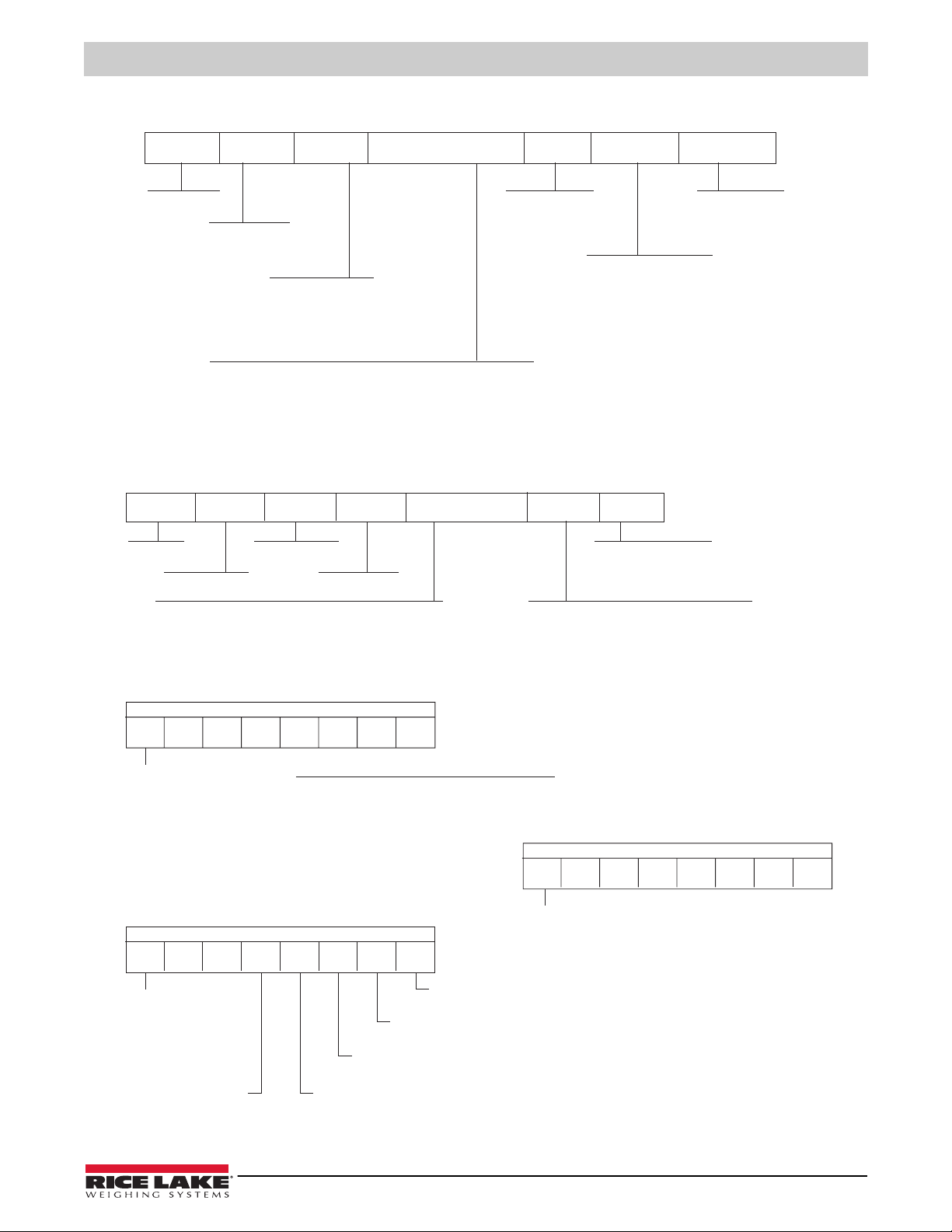
10.3.3 Avery Weigh-Tronix Stream Format (wtrnix)
Space
Polarity:
<+> for positive
"–" for negative
Six digits, right justified, floating decimal,
leading zeros are present
g for Gross
n for Net
<CR><LF>
or
<CR>
lb = pound
kg = kilogram
g = gram
tn = ton (short)
t = ton (metric)
oz = ounce
<space> = none
Space
<SP> <G/N> <POL> <wwwwww> <SP> <UNIT> <TERM>
<STX> <SWA> <SWB> <SWC> <wwwwww> <tttttt> <CR>
ASCII 002
Status Word A
<CR> entered at end
of string.
Status Word B
Status Word C
MUL1 MUL0Parity
DP2 DP1 DP0 Fixed Zero/Dec. Pt. Location
0 0 0 x 100 (2 fixed zeroes)
0 0 1 x 10 (1 fixed zero)
0 1 0 x 1 (No decimal point)
0 1 1 x 0.1 (1 decimal place)
1 0 0 x 0.01 (2 decimal places)
1 0 1 x 0.001 (3 decimal places)
1 1 0 x 0.0001 (4 decimal places)
1 1 1 x 0.00001 (5 decimal places)
Disp. Div.
MUL1
MUL0
Multiplier
0 1 x 1
1 0 x 2
1 1 x 5
Even parity bit.
Requires EDP Port setup.
Status Word A:
Status Word C: ASCII 20h (space)
Even parity bit:
Requires EDP Port setup.
Status Word B:
0 = Gross Display Mode
1 = Net Display Mode
0 = Positive indicated weight value
1 = Negative indicated weight value
0 = In range
1 = Out of range
0 = Stable
1 = Motion
0 = lb
1 = kg
Even parity bit:
Requires EDP Port
setup.
Six digits, right justified, dummy zeros, decimal
point with no leading zeroes except for immediately
preceding the decimal point. Leading zeroes
transmitted as spaces.
Tare Weight: Six digits, right justified,
dummy zeros, decimal point with no
leading zeroes except for immediately
preceding the decimal point.
Leading zeroes transmitted as spaces.
76543210
DP2 DP1 DP010
Parity
76543210
1000000
Parity
76543210
10
Figure 10-3. Avery Weigh-Tronix Stream Data Format
10.3.4 Mettler Toledo Stream Format (toledo)
Appendix
Figure 10-4. Mettler Toledo Stream Data Format
© Rice Lake Weighing Systems ● All Rights Reserved 55
Page 56

380/381 Synergy Indicator
10.4 Conversion Factors for Secondary Units
The 380/381 has the capability to mathematically convert a weight into another unit of measurement and display the result with
the press of the Units key. Available units are pounds (lb), kilograms (kg), tonnes (t), grams (g), short ton (tn) and ounces (oz).
Secondary units can be specified on the Format menu using the SECNDR parameter.
NOTE: Multipliers are preconfigured within the indicator.
NOTE: Ensure the secondary decimal point position is set appropriately for the scale capacity in the secondary units.
10.5 Digital Filtering
Digital filtering is used to create a stable scale reading in challenging environments. The 380/381 allows selection of Digital
Rolling Average Filtering (
and the location of
The scale’s sample rate effects all types of filtering. The A/D sample rate is selected by the SMPRAT scale parameter. The A/D
sample rate is the number of weight readings the indicator takes per second (SMPRAT). This can be 5, 6, 10, 12, 20, 25, 40, 50,
80, or 100 hertz (readings per second). Set the A/D sample rate to the lowest setting required for the application. Lower settings
result in better stability.
FLTCHN
10.5.1 Digital Rolling Average Filter (AVGONLY)
The digital rolling average filter uses mathematical averaging with three stages. These configurable stages control the effect of
a single A/D reading on the displayed weight. When an A/D reading outside of a predetermined band (defined by the DFSENS
and DFTHRH parameters) is encountered, the digital rolling average filter is overridden and the display jumps directly to the
new value.
Section 10.5.1
parameter.
) or
RAW
(no filtering).
See
Section 4.3.1 on page 33
for configuration menu layout
Digital Filter Stages (DGFLTR1-3)
The filter stages can each be set to a value of 1–256. The value assigned to each stage sets the number of readings received
from the preceding filter stage before averaging. Setting the filter stages to 1 effectively disables the rolling filter.
A rolling average is passed to successive filtering stages for an overall filtering effect which is effectively a weighted average of
the product of the values assigned to the filter stages (DGFLTR1 x DGFLTR2 x DGFLTR3) within a time frame corresponding
to the sum of the values (DGFLTR1 + DGFLTR2 + DGFLTR3).
Digital Filter Sensitivity (DFSENS) and Threshold (DFTHRH)
The rolling averaging filter can be used by itself to eliminate vibration effects, but heavy filtering also increases settling time.
The DFSENS and DFTHRH parameters can be used to temporarily override filter averaging and improve settling time.
• DFSENS specifies the number of consecutive A/D readings which must fall outside the filter threshold (DFTHRH) before
filtering is suspended
• DFTHRH sets a controlling threshold delta value, in display divisions; the indicator monitors both the incoming filtered
and unfiltered A/D values; DFTHRH is the maxim allowable difference between the filtered and unfiltered A/D values for
which the filter will remain engaged; filtering is suspended when the difference between the filtered and unfiltered A/D
values is greater than the DFTHRH value for more than the specified number (DFSENS) of consecutive readings;
filtering is reengaged when two consecutive A/D readings are within the DFTHRH threshold delta value; Set DFTHRH to
NONE to turn off the filter override
56 Visit our website www.RiceLake.com
Page 57
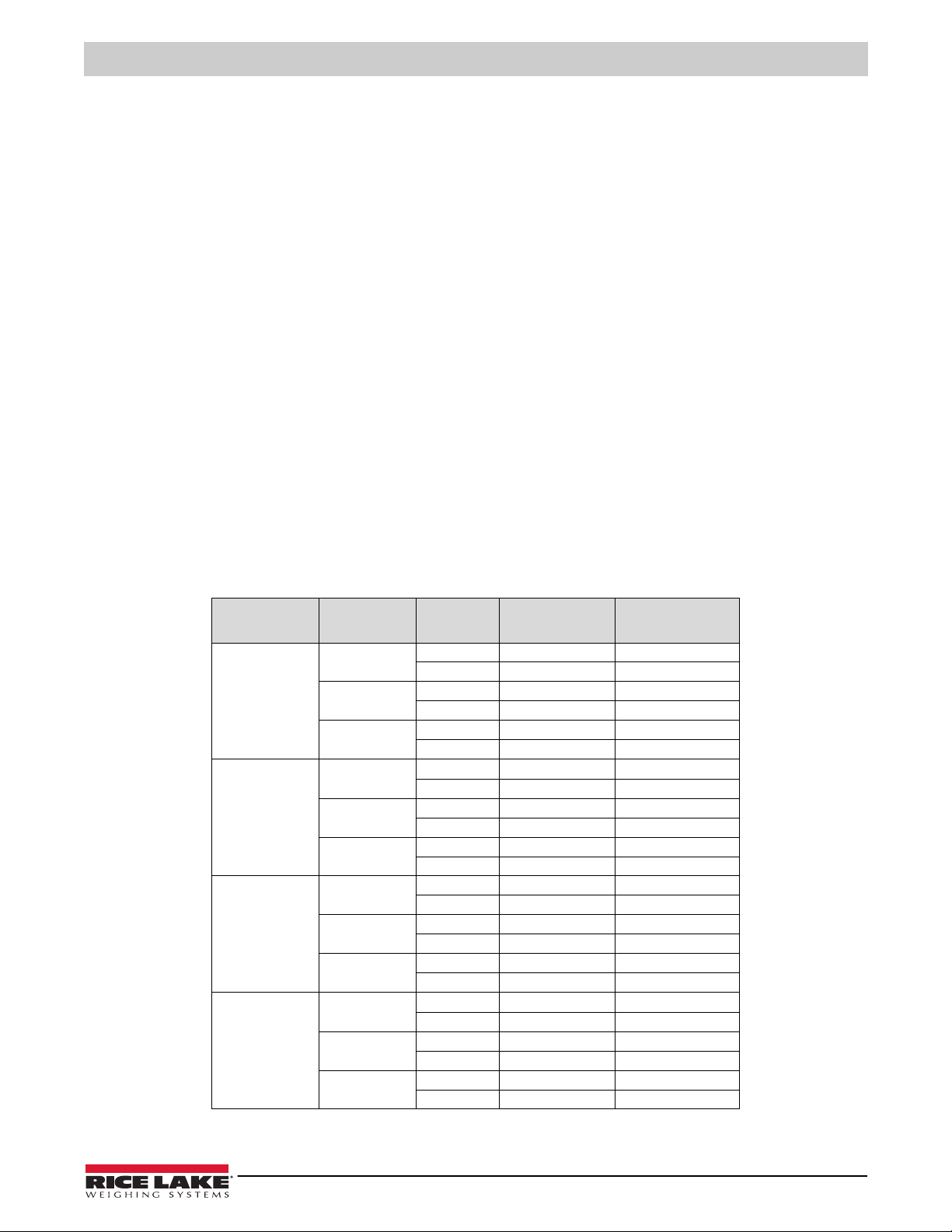
Appendix
Digital Rolling Average Filter Procedure
1. In setup mode, set the rolling filter stage parameters (DGFLTR1-3) to 1.
2. Set DFTHRH to NONE.
3. Return to weigh mode.
4. Remove all weight from scale, then watch the indicator to determine the magnitude of vibration effects on the scale.
5. Record weight below which all but a few readings fall. This value is used to calculate the DFTHRH parameter in step 8.
Example – if a heavy-capacity scale (10000 x 5 lb) produces vibration-related readings of up to 50 lb, with occasional
spikes up to 75 lb, record 50 as the threshold weight value.
6. Place the indicator in setup mode and set the filter stage parameters (DGFLTR1-3) to eliminate the vibration effects on
the scale (leave DFTHRH set to NONE).
7. Find the lowest effect value for the DGFLTR1-3 parameters.
If needed, the digital filter cutout sensitivity (DFSENS) and the digital filter cutout threshold (DFTHRH) can be used to reset the
digital rolling average filter so the response to a rate change is faster.
8. Calculate the DFTHRH parameter value by converting the weight value recorded in step 5 to display divisions
(Threshold_Weight_Value / Display_Divisions).
In the example in step 5, with a threshold value of 50, and a display divisions value of 5, set the DFTHRH parameter to
10 display divisions.
9. Set the DFSENS parameter high enough to ignore transient peaks. Longer transients (typically caused by lower
vibration frequencies) causes more consecutive out-of-band readings; set the DFSENS parameter higher to counter
low frequency transients.
10.5.2 Regulatory Mode Functions
Regulatory
Parameter
NTEP Zero No “000000” Zero
Negative No No action Zero
Positive No Tare Zero
Canada Zero No “000000” Zero
Negative No No action Zero
Positive No Tare Zero
OIML Zero No “000000” Zero
Negative No No action Zero
Positive No “000000” Zero
None Zero No “000000” Zero
Negative No No action Zero
Positive No Tare Zero
Table 10-3. Tare and Zero Key Functions for REGULA Parameter Settings
Weight On
Scale
Tare In
System
Yes Clear tare Zero
Yes Clear tare Zero
Yes Tare Zero
Yes Clear tare Clear tare
Yes Clear tare Clear tare
Yes No action Clear tare
Yes Clear tare Zero and Clear tare
Yes Clear tare Zero and Clear tare
Yes Tare Zero and Clear Tare
Yes Clear tare Clear tare
Yes Clear tare Clear tare
Yes Clear tare Clear tare
Front Panel
Key Tare
Front Panel
Key Zero
© Rice Lake Weighing Systems ● All Rights Reserved 57
Page 58
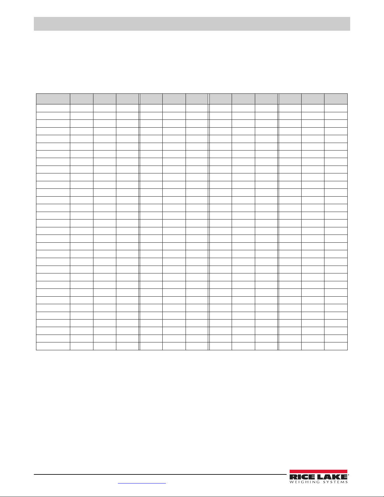
380/381 Synergy Indicator
10.6 ASCII Character Chart
Use the decimal values for ASCII characters listed in Table 10-4 when specifying print format strings on the 380/381 PFORMT
menu (Section 4.3.6 on page 37). The actual character printed depends on the character mapping used by the output device.
The 380/381 can send or receive ASCII character values (decimal 0–255), but the indicator display is limited to numbers,
uppercase,
LCD display.
Ctrl-@ NUL 00 00 space 32 20 @ 64 40 ` 96 60
Ctrl-A SOH 01 01 ! 33 21 A 65 41 a 97 61
Ctrl-B STX 02 02 “ 34 22 B 66 42 b 98 62
Ctrl-C ETX 03 03 # 35 23 C 67 43 c 99 63
Ctrl-D EOT 04 04 $ 36 24 D 68 44 d 100 64
Ctrl-E ENQ 05 05 % 37 25 E 69 45 e 101 65
Ctrl-F ACK 06 06 & 38 26 F 70 46 f 102 66
Ctrl-G BEL 07 07 ’ 39 27 G 71 47 g 103 67
Ctrl-H BS 08 08 ( 40 28 H 72 48 h 104 68
Ctrl-I HT 09 09 ) 41 29 I 73 49 i 105 69
Ctrl-J LF 10 0A * 42 2A J 74 4A j 106 6A
Ctrl-K VT 11 0B + 43 2B K 75 4B k 107 6B
Ctrl-L FF 12 0C , 44 2C L 76 4C l 108 6C
Ctrl-M CR 13 0D - 45 2D M 77 4D m 109 6D
Ctrl-N SO 14 0E . 46 2E N 78 4E n 110 6E
Ctrl-O SI 15 0F / 47 2F O 79 4F o 111 6F
Ctrl-P DLE 16 10 0 48 30 P 80 50 p 112 70
Ctrl-Q DC1 17 11 1 49 31 Q 81 51 q 113 71
Ctrl-R DC2 18 12 2 50 32 R 82 52 r 114 72
Ctrl-S DC3 19 13 3 51 33 S 83 53 s 115 73
Ctrl-T DC4 20 14 4 52 34 T 84 54 t 116 74
Ctrl-U NAK 21 15 5 53 35 U 85 55 u 117 75
Ctrl-V SYN 22 16 6 54 36 V 86 56 v 118 76
Ctrl-W ETB 23 17 7 55 37 W 87 57 w 119 77
Ctrl-X CAN 24 18 8 56 38 X 88 58 x 120 78
Ctrl-Y EM 25 19 9 57 39 Y 89 59 y 121 79
Ctrl-Z SUB 26 1A : 58 3A Z 90 5A z 122 7A
Ctrl-[ ESC 27 1B ; 59 3B [ 91 5B { 123 7B
Ctrl-\ FS 28 1C < 60 3C \ 92 5C | 124 7C
Ctrl-] GS 29 1D = 61 3D ] 93 5D } 125 7D
Ctrl-^ RS 30 1E > 62 3E ^ 94
Ctrl-_ US 31 1F ? 63 3F _ 95 5F DEL 127 7F
unaccented letters and a few special characters. See Section 10.7 on page 59 for information about the 380/381
Control ASCII Dec Hex ASCII Dec Hex ASCII Dec Hex ASCII Dec Hex
5E ~ 126 7
Table 10-4. ASCII Character Chart
E
58 Visit our website www.RiceLake.com
Page 59
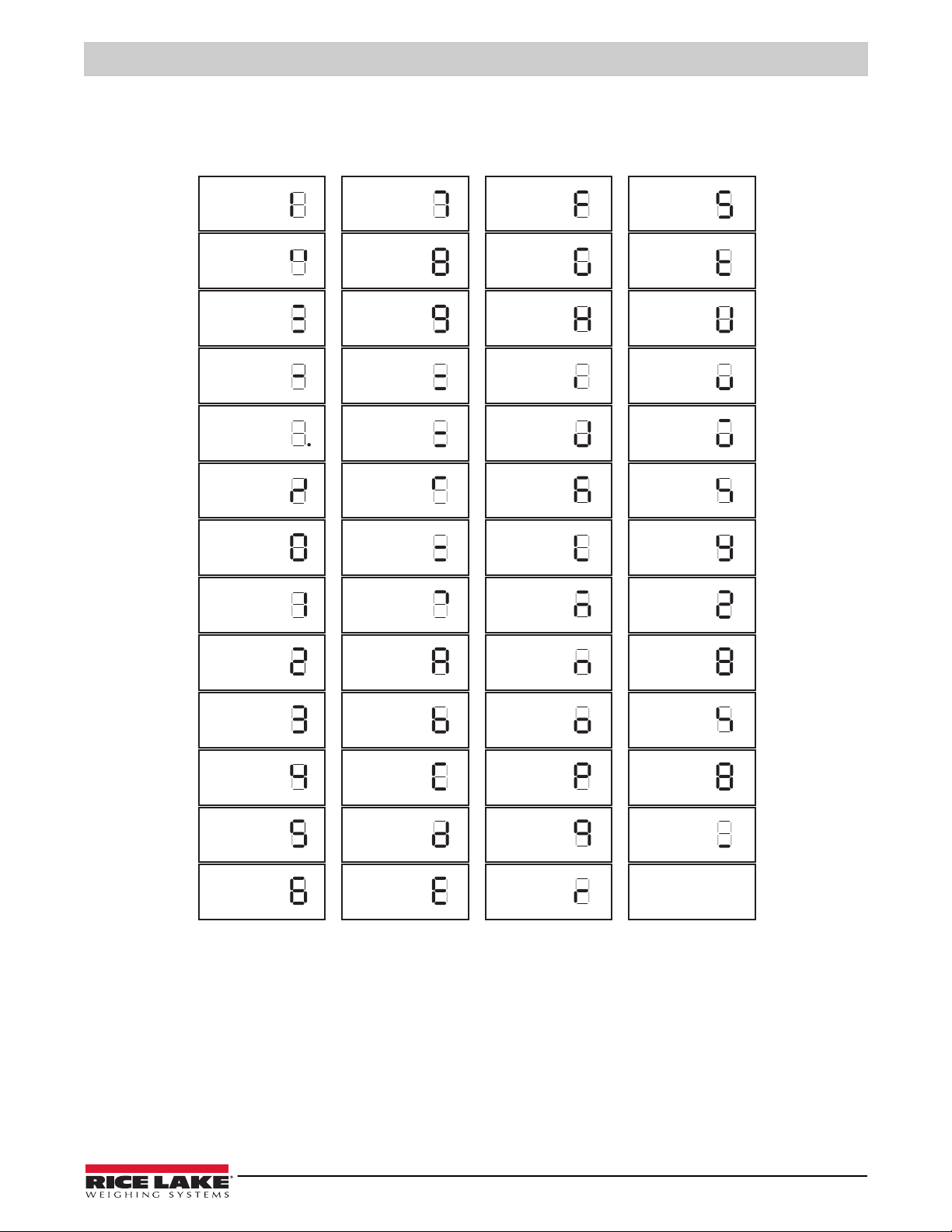
Appendix
! 7 Ff Ss
" 8 Gg Tt
+ 9 Hh Uu
-:IiVv
.
;JjWw
/ < Kk Xx
0 = Ll Yy
1 > Mm Zz
2AaNn[
3BbOo\
4 CcPp]
5DdQq_
6EeRr
10.7 Front Panel Display Characters
Refer to Figure 10-5 for the seven-segment LCD character set used on the 380/381 front panel display for alphanumeric
characters.
Figure 10-5. Display Characters
© Rice Lake Weighing Systems ● All Rights Reserved 59
Page 60
380/381 Synergy Indicator
5LFH/DNH:HLJKLQJ6\VWHPV
:HVW &ROHPDQ 6WUHHW
5LFH /DNH :LVFRQVLQ
8QLWHG 6WDWHV RI$PHULFD
6LJQDWXUH
3ODFH
1DPH 'DWH
7LWOH
(8DECLARATIONOF
CONFORMITY
("#+,.$-#0#(1
#/ ( #&1
(88'LUHFWLYH &HUWLILFDWHV
6WDQGDUGVV8VHGG1RWLILHGG%RG\\,QYROYHPHQWW
__________________________
__________________________
5LFH/DNH:,86$
__________________________
7\SH7\S7\SH
(QJOLVK :H GHFODUHXQGHURXUVROH UHVSRQVLELOLW\WKDW WKHSURGXFWVWR ZKLFKWKLV GHFODUDWLRQUHIHUV WRLV LQFRQIRUPLW\ ZLWK WKHIROORZLQJ
VWDQGDUGV RURWKHUUHJXODWLRQVGRFXPHQWV
'HXWVFK :LUHUNOlUHQXQWHUXQVHUHU DOOHLQLJHQ9HUDQWZRUWXQJ GDVV GLH 3URGXNWHDXI GLHVLFK GLHVH(UNOlUXQJEH]LHKW GHQIROJHQGHQ 1RUPHQ
XQG 5HJXOLHUXQJVEHVWLPPXQJHQHQWVSUHFKHQ
)UDQFDLV 1RXVGpFODURQVVRXVQRWUHUHVSRQVDELOLWpTXHOHVSURGXLWVDX[TXHOVVHUDSSRUWHODSUpVHQWHGpFODUWLRQVRQWFRQIRUPHVjODDX[QRUPHV
VXLYDQWHRXDXDX[GRFXPHQWVQRUPDWLIVVXLYDQWV
BBBBBBBBBBBBBBBBBBBBBBBBBBBBBBBBBBBBB
BBBBBBBBBBBBBBBBBBBBBBBBBBBBBBBBBBBBB
_______
____
____
__
___
______________
11.0 Compliance
380 indicator series
2014/35/EU LVD
2014/30/EU EMC
2014/53/EU RED
2011/65/EU RoHS
-
-
-
-
IEC 62368-1:2014
EN 61326-1:2013, EN 61000-3-2:2014, EN 61000-3-3:2013
EN 300 328:2019, EN 301 489-17:2020
EN 50581:2012
Brandi Harder
Quality Manager
60 Visit our website www.RiceLake.com
September 17, 2021
Page 61

Compliance
5LFH/DNH:HLJKLQJ6\VWHPV
:HVW &ROHPDQ 6WUHHW
5LFH /DNH :LVFRQVLQ
8QLWHG 6WDWHV RI$PHULFD
6LJQDWXUH
3ODFH
1DPH 'DWH
7LWOH
8. DECLARATION
OFCONFORMITY
8..5HJXODWLRQV &HUWLILFDWHV
6WDQGDUGVV8VHGG$SSURYHGG%RG\\,QYROYHPHQWW
7\SH
(QJOLVK :H GHFODUHXQGHU RXUVROH UHVSRQVLELOLW\WKDW WKH SURGXFWVWR ZKLFKWKLV GHFODUDWLRQUHIHUV WRLVLQFRQIRUPLW\ ZLWK WKH IROORZLQJ
VWDQGDUGV RURWKHUUHJXODWLRQVGRFXPHQWV
)RUP 5HY
BBBBBBBBBBBBBBBBBBBBBBBBBBBBBBBBBBBBB
$SSURYHGE\4XDOLW\'HSDUWPHQW
BBBBBBBBBBBBBBBBBBBBBBBBBBBBBBBBBBBBB
BBBBBBBBBBBBBBBBBBBBBBBBBBBBBBBBBBBBB
BBBBBBBBBBBBBBBBBBBBBBBBBBBBBBBBBBBBB
BBBBBBBBBBBBBBBBBBBBBBBBBBBBBBBBBBBBB
BBBBBBBBBBBBBBBBBBBBBBBBBBBBBBBB
380 indicator series
2016/1101 Low Voltage
2016/1091 EMC
2017/1206 Radio
2012/3032 RoHS
-
-
-
-
IEC 62368-1:2014
EN 61326-1:2013, EN 61000-3-2:2014, EN 61000-3-3:2013
EN 300 328:2019, EN 301 489-17:2020
EN 50581:2012
Brandi Harder
Quality Manager
Rice Lake, WI USA
March 7, 2022
© Rice Lake Weighing Systems ● All Rights Reserved 61
Page 62
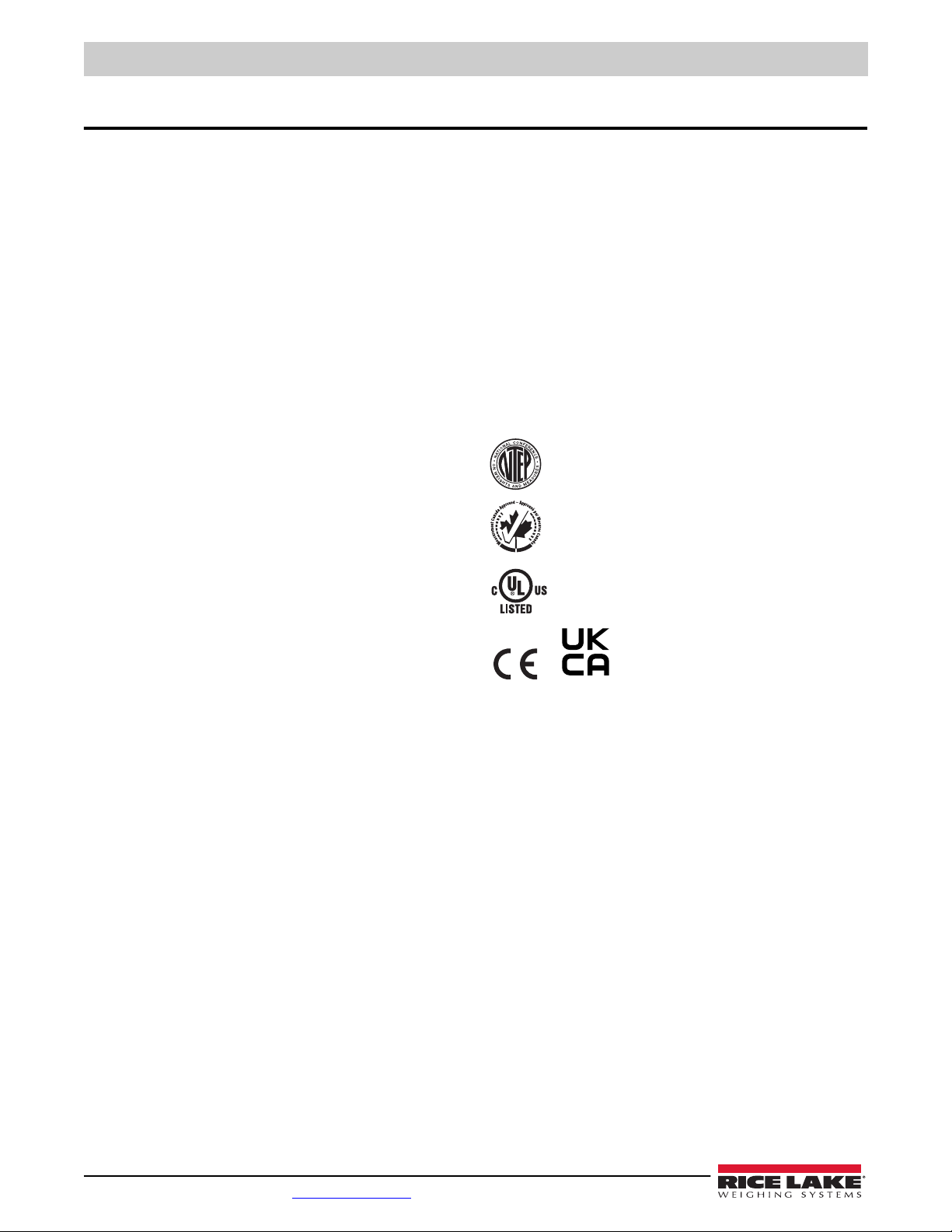
380/381 Synergy Indicator
12.0 Specifications
380-2D (PN 202711)
Power
Four Alkaline C-Cell Batteries
Optional 115/230 VAC to 12 V adapter
Power Consumption
8.5 W max with optional external power adapter
Battery Life
100 hours on Alkaline batteries with one 350Ω load cell, no backlight
45 hours on Alkaline batteries with four 350Ω load cells, low backlight
20 hours on Alkaline batteries with eight 350Ω load cells, low backlight
Excitation Voltage
5 VDC, 8 x 350Ω or 16 x 700Ω load cells
Analog Signal Input Range
-0.3 mV to +30 mV
Common Mode Voltage 0.7 V to 3.3 V
Analog Signal Sensitivity
1 µV/graduation recommended
A/D Sample Rate
Software Selectable (Hz)
5, 6, 10, 12, 20, 25, 40, 50, 80, 100
Temperature Range
Legal: 14–104°F (-10–40°C)
Industrial: 14–122°F (-10–50°C)
Rating/Material
Rating: IP66
Material: Stainless Steel
Warranty
Two-year limited warranty
EMC Immunity
10 V/m
Certifications and Approvals
380 Universal
NTEP
CoC Number: 21-051A1
Accuracy Class: III / IIIL; n
Measurement Canada
Approval Number: AM-6184
Accuracy Class: III / IIIHD; n
UL
File Number: E151461
max
: 10 000
: 10 000
max
Resolution
Internal: 8,000,000 counts
Display: 100,000
System Linearity
Within 0.01% full scale
Communication Ports
One RS-232 (three-wire)
One USB 2.0
Status Annunciators
g, lb, t, tn, kg, oz, battery level, PT, LT, gross, zero, unstable, net
Display
Six 1.0 in (25 mm) tall, LCD digits
Keys / Buttons
Five tactile buttons
Dimensions (L x W x H)
11.58 x 74.53 x 8.57 in (294 x 115 x 218 mm)
62 Visit our website www.RiceLake.com
Page 63

Specifications
381-2D-AA (PN 215695) / 381-2D-NiMH (PN 215696)
Power
Battery: AA or Nickel Metal Hydride (niMH)
381-2D-AA Adapter: 115/230 VAC to 12 VDC
381-2D-NiMH Charger: 115/230 VAC
Power Consumption
AA: input 0.8 A
NiMH: input of 0.35 A
Battery Life
AA: 40 hours with 1 x 350 ohm load cell
NiMH: 80 hours with 1 x 350 ohm load cell
Excitation Voltage
5 VDC, 8 x 350Ω or 16 x 700Ω load cells
Analog Signal Input Range
-0.3 mV to +30 mV
Common Mode Voltage 0.7 V to 3.3 V
Analog Signal Sensitivity
1 µV/graduation recommended
A/D Sample Rate
Software Selectable (Hz)
5, 6, 10, 12, 20, 25, 40, 50, 80, 100
Rating/Material
AA Battery: IP54, ABS
NiMH Battery: IP66, ABS
Warranty
Two-year limited warranty
EMC Immunity
10 V/m
Certifications and Approvals
NTEP
CoC Number: 21-051A1
Accuracy Class: III / IIIL; n
Measurement Canada
Approval Number: AM-6184
Accuracy Class: III / IIIHD; n
: 10 000
max
max
: 10 000
Resolution
Internal: 8,000,000 counts
Display: 100,000
System Linearity
Within 0.01% full scale
Communication Ports
One RS-232 (three-wire)
One USB 2.0
Status Annunciators
g, lb, t, tn, kg, oz, battery level, PT, LT, gross, zero, unstable, net
Display
Six 1.0 in (25 mm) tall, LCD digits
Keys / Buttons
Five tactile buttons
Dimensions (L x W x H)
8.50 x 3.17 x 5.06 in (215.8 x 80.5 x 128.5 mm)
Temperature Range
Legal: 14–104°F (-10–40°C)
Industrial: 14–122°F (-10–50°C)
© Rice Lake Weighing Systems ● All Rights Reserved 63
Page 64

380/381 Synergy Indicator
64 Visit our website www.RiceLake.com
Page 65

Page 66

230 W. Coleman St. • Rice Lake, WI 54868 • USA
U.S. 800-472-6703 • Canada/Mexico 800-321-6703 • International 715-234-9171 • Europe +31 (0)26 472 1319
© Rice Lake Weighing Systems Specifications subject to change without notice.
www.ricelake.com
August 16, 2023
PN 201481 Rev G
 Loading...