

Page 1
320IS Plus
Intrinsically Safe Digital Weight Indicator
Version 2.4
Installation Manual
PN 85353 Rev D
Page 2

Page 3

Contents
Technical training seminars are available through Rice Lake Weighing Systems.
Course descriptions and dates can be viewed at www.ricelake.com/training
or obtained by calling 715-234-9171 and asking for the training department.
1.0 Introduction.................................................................................................................................. 1
Safety ....................................................................................................................................................... 1
1.1 Overview . . . . . . . . . . . . . . . . . . . . . . . . . . . . . . . . . . . . . . . . . . . . . . . . . . . . . . . . . . . . . . . . . . . . . . 2
1.2 Factory Mutual Approval. . . . . . . . . . . . . . . . . . . . . . . . . . . . . . . . . . . . . . . . . . . . . . . . . . . . . . . . . . . 2
1.3 Operating Modes . . . . . . . . . . . . . . . . . . . . . . . . . . . . . . . . . . . . . . . . . . . . . . . . . . . . . . . . . . . . . . . . 2
1.4 Front Panel Keypad . . . . . . . . . . . . . . . . . . . . . . . . . . . . . . . . . . . . . . . . . . . . . . . . . . . . . . . . . . . . . . 3
1.5 Front Panel Configuration . . . . . . . . . . . . . . . . . . . . . . . . . . . . . . . . . . . . . . . . . . . . . . . . . . . . . . . . . . 5
1.6 LED Annunciators. . . . . . . . . . . . . . . . . . . . . . . . . . . . . . . . . . . . . . . . . . . . . . . . . . . . . . . . . . . . . . . . 6
1.7 Indicator Operations . . . . . . . . . . . . . . . . . . . . . . . . . . . . . . . . . . . . . . . . . . . . . . . . . . . . . . . . . . . . . . 7
1.7.1 Toggle Gross/Net Mode . . . . . . . . . . . . . . . . . . . . . . . . . . . . . . . . . . . . . . . . . . . . . . . . . . . . . . . . . . . . 7
1.7.2 Toggle Units . . . . . . . . . . . . . . . . . . . . . . . . . . . . . . . . . . . . . . . . . . . . . . . . . . . . . . . . . . . . . . . . . . . . . 7
1.7.3 Zero Scale. . . . . . . . . . . . . . . . . . . . . . . . . . . . . . . . . . . . . . . . . . . . . . . . . . . . . . . . . . . . . . . . . . . . . . . 7
1.7.4 Acquire Tare . . . . . . . . . . . . . . . . . . . . . . . . . . . . . . . . . . . . . . . . . . . . . . . . . . . . . . . . . . . . . . . . . . . . . 7
1.7.5 Remove Stored Tare Value . . . . . . . . . . . . . . . . . . . . . . . . . . . . . . . . . . . . . . . . . . . . . . . . . . . . . . . . . . 7
1.7.6 Alternate Method to Remove Tare. . . . . . . . . . . . . . . . . . . . . . . . . . . . . . . . . . . . . . . . . . . . . . . . . . . . . 7
1.7.7 Acquire Parts Sample . . . . . . . . . . . . . . . . . . . . . . . . . . . . . . . . . . . . . . . . . . . . . . . . . . . . . . . . . . . . . . 7
1.7.8 Display Part Weight. . . . . . . . . . . . . . . . . . . . . . . . . . . . . . . . . . . . . . . . . . . . . . . . . . . . . . . . . . . . . . . . 8
1.7.9 Display or Change Time/Date . . . . . . . . . . . . . . . . . . . . . . . . . . . . . . . . . . . . . . . . . . . . . . . . . . . . . . . . 8
1.7.10 Print Ticket . . . . . . . . . . . . . . . . . . . . . . . . . . . . . . . . . . . . . . . . . . . . . . . . . . . . . . . . . . . . . . . . . . . . . . 8
1.7.11 Display or Change Setpoint Value . . . . . . . . . . . . . . . . . . . . . . . . . . . . . . . . . . . . . . . . . . . . . . . . . . . . . 8
1.7.12 Turn Setpoint On or Off. . . . . . . . . . . . . . . . . . . . . . . . . . . . . . . . . . . . . . . . . . . . . . . . . . . . . . . . . . . . . 8
1.7.13 Display or Clear Accumulator . . . . . . . . . . . . . . . . . . . . . . . . . . . . . . . . . . . . . . . . . . . . . . . . . . . . . . . . 8
2.0 Installation ................................................................................................................................... 9
2.1 Unpacking and Assembly . . . . . . . . . . . . . . . . . . . . . . . . . . . . . . . . . . . . . . . . . . . . . . . . . . . . . . . . . . 9
2.2 Enclosure Disassembly. . . . . . . . . . . . . . . . . . . . . . . . . . . . . . . . . . . . . . . . . . . . . . . . . . . . . . . . . . . . 9
2.3 Hazardous Area Installation of the 320IS Plus. . . . . . . . . . . . . . . . . . . . . . . . . . . . . . . . . . . . . . . . . . 10
2.3.1 Power Supply to Indicator . . . . . . . . . . . . . . . . . . . . . . . . . . . . . . . . . . . . . . . . . . . . . . . . . . . . . . . . . . 10
2.3.2 AC Power Wiring. . . . . . . . . . . . . . . . . . . . . . . . . . . . . . . . . . . . . . . . . . . . . . . . . . . . . . . . . . . . . . . . . 11
2.3.3 Battery Option. . . . . . . . . . . . . . . . . . . . . . . . . . . . . . . . . . . . . . . . . . . . . . . . . . . . . . . . . . . . . . . . . . . 11
2.4 Cable Connections and Installation. . . . . . . . . . . . . . . . . . . . . . . . . . . . . . . . . . . . . . . . . . . . . . . . . . 11
2.4.1 Braided Power Cable Connection with Ferrite Core. . . . . . . . . . . . . . . . . . . . . . . . . . . . . . . . . . . . . . . 12
2.4.2 Braided Power Cable Connection Without Ferrite Core . . . . . . . . . . . . . . . . . . . . . . . . . . . . . . . . . . . . 13
2.4.3 Braided Load Cell Cable Connection . . . . . . . . . . . . . . . . . . . . . . . . . . . . . . . . . . . . . . . . . . . . . . . . . 13
2.4.4 Foil Load Cell Cable Connection . . . . . . . . . . . . . . . . . . . . . . . . . . . . . . . . . . . . . . . . . . . . . . . . . . . . . 14
2.4.5 Load Cells. . . . . . . . . . . . . . . . . . . . . . . . . . . . . . . . . . . . . . . . . . . . . . . . . . . . . . . . . . . . . . . . . . . . . . 15
2.5 Fiber Optics Installation . . . . . . . . . . . . . . . . . . . . . . . . . . . . . . . . . . . . . . . . . . . . . . . . . . . . . . . . . . 16
2.5.1 Assembling Fiber Optics Connectors. . . . . . . . . . . . . . . . . . . . . . . . . . . . . . . . . . . . . . . . . . . . . . . . . . 16
2.6 Enclosure Reassembly . . . . . . . . . . . . . . . . . . . . . . . . . . . . . . . . . . . . . . . . . . . . . . . . . . . . . . . . . . . 16
2.7 Control Drawings . . . . . . . . . . . . . . . . . . . . . . . . . . . . . . . . . . . . . . . . . . . . . . . . . . . . . . . . . . . . . . . 19
3.0 Configuration ............................................................................................................................. 21
3.1 Configuration Methods . . . . . . . . . . . . . . . . . . . . . . . . . . . . . . . . . . . . . . . . . . . . . . . . . . . . . . . . . . . 21
3.1.1 Revolution Configuration . . . . . . . . . . . . . . . . . . . . . . . . . . . . . . . . . . . . . . . . . . . . . . . . . . . . . . . . . . . 21
3.1.2 EDP Command Configuration . . . . . . . . . . . . . . . . . . . . . . . . . . . . . . . . . . . . . . . . . . . . . . . . . . . . . . . 21
3.1.3 Front Panel Configuration . . . . . . . . . . . . . . . . . . . . . . . . . . . . . . . . . . . . . . . . . . . . . . . . . . . . . . . . . . 21
3.2 Menu Structures and Parameter Descriptions. . . . . . . . . . . . . . . . . . . . . . . . . . . . . . . . . . . . . . . . . . 22
3.2.1 Configuration Menu. . . . . . . . . . . . . . . . . . . . . . . . . . . . . . . . . . . . . . . . . . . . . . . . . . . . . . . . . . . . . . . 23
© Rice Lake Weighing Systems. All rights reserved. Printed in the United States of America.
Rice Lake Weighing Systems is an ISO 9001 registered company.
Specifications subject to change without notice.
Version 2.4, October 2014
Contents i
Page 4

3.2.2 Format Menu . . . . . . . . . . . . . . . . . . . . . . . . . . . . . . . . . . . . . . . . . . . . . . . . . . . . . . . . . . . . . . . . . . . 25
Rice Lake continually offers web-based video training on a growing selection
of product-related topics at no cost. Visit www.ricelake.com/webinars.
3.2.3 Calibration Menu. . . . . . . . . . . . . . . . . . . . . . . . . . . . . . . . . . . . . . . . . . . . . . . . . . . . . . . . . . . . . . . . . 27
3.2.4 Serial Menu. . . . . . . . . . . . . . . . . . . . . . . . . . . . . . . . . . . . . . . . . . . . . . . . . . . . . . . . . . . . . . . . . . . . . 28
3.2.5 Program Menu . . . . . . . . . . . . . . . . . . . . . . . . . . . . . . . . . . . . . . . . . . . . . . . . . . . . . . . . . . . . . . . . . . 30
3.2.6 Print Format Menu . . . . . . . . . . . . . . . . . . . . . . . . . . . . . . . . . . . . . . . . . . . . . . . . . . . . . . . . . . . . . . . 31
3.2.7 Setpoint Menu . . . . . . . . . . . . . . . . . . . . . . . . . . . . . . . . . . . . . . . . . . . . . . . . . . . . . . . . . . . . . . . . . . 32
3.2.8 Analog Output Menu. . . . . . . . . . . . . . . . . . . . . . . . . . . . . . . . . . . . . . . . . . . . . . . . . . . . . . . . . . . . . . 38
3.2.9 Version Menu . . . . . . . . . . . . . . . . . . . . . . . . . . . . . . . . . . . . . . . . . . . . . . . . . . . . . . . . . . . . . . . . . . . 40
4.0 Calibration ................................................................................................................................. 41
4.1 Front Panel Calibration. . . . . . . . . . . . . . . . . . . . . . . . . . . . . . . . . . . . . . . . . . . . . . . . . . . . . . . . . . . 41
4.2 EDP Command Calibration . . . . . . . . . . . . . . . . . . . . . . . . . . . . . . . . . . . . . . . . . . . . . . . . . . . . . . . 42
4.3 Revolution® Calibration . . . . . . . . . . . . . . . . . . . . . . . . . . . . . . . . . . . . . . . . . . . . . . . . . . . . . . . . . . 42
5.0 EDP Commands.......................................................................................................................... 44
5.1 The EDP Command Set . . . . . . . . . . . . . . . . . . . . . . . . . . . . . . . . . . . . . . . . . . . . . . . . . . . . . . . . . 44
5.1.1 Key Press Commands . . . . . . . . . . . . . . . . . . . . . . . . . . . . . . . . . . . . . . . . . . . . . . . . . . . . . . . . . . . . 44
5.1.2 Reporting Commands. . . . . . . . . . . . . . . . . . . . . . . . . . . . . . . . . . . . . . . . . . . . . . . . . . . . . . . . . . . . . 45
5.1.3 The RESETCONFIGURATION Command . . . . . . . . . . . . . . . . . . . . . . . . . . . . . . . . . . . . . . . . . . . . . . 46
5.1.4 Parameter Setting Commands . . . . . . . . . . . . . . . . . . . . . . . . . . . . . . . . . . . . . . . . . . . . . . . . . . . . . . 46
5.1.5 Normal Mode Commands. . . . . . . . . . . . . . . . . . . . . . . . . . . . . . . . . . . . . . . . . . . . . . . . . . . . . . . . . . 50
5.1.6 Batching Control Commands . . . . . . . . . . . . . . . . . . . . . . . . . . . . . . . . . . . . . . . . . . . . . . . . . . . . . . . 50
5.2 Saving and Transferring Data. . . . . . . . . . . . . . . . . . . . . . . . . . . . . . . . . . . . . . . . . . . . . . . . . . . . . . 52
5.2.1 Saving Indicator Data to a Personal Computer . . . . . . . . . . . . . . . . . . . . . . . . . . . . . . . . . . . . . . . . . . 52
5.2.2 Downloading Configuration Data from PC to Indicator . . . . . . . . . . . . . . . . . . . . . . . . . . . . . . . . . . . . 52
6.0 Print Formatting ......................................................................................................................... 53
6.1 Print Formatting Commands . . . . . . . . . . . . . . . . . . . . . . . . . . . . . . . . . . . . . . . . . . . . . . . . . . . . . . 53
6.2 Customizing Print Formats. . . . . . . . . . . . . . . . . . . . . . . . . . . . . . . . . . . . . . . . . . . . . . . . . . . . . . . . 54
6.2.1 Using the EDP Port. . . . . . . . . . . . . . . . . . . . . . . . . . . . . . . . . . . . . . . . . . . . . . . . . . . . . . . . . . . . . . . 54
6.2.2 Using the Front Panel . . . . . . . . . . . . . . . . . . . . . . . . . . . . . . . . . . . . . . . . . . . . . . . . . . . . . . . . . . . . . 55
6.2.3 Using Revolution® . . . . . . . . . . . . . . . . . . . . . . . . . . . . . . . . . . . . . . . . . . . . . . . . . . . . . . . . . . . . . . . 55
7.0 Setpoints .................................................................................................................................... 56
7.1 Batch and Continuous Setpoints . . . . . . . . . . . . . . . . . . . . . . . . . . . . . . . . . . . . . . . . . . . . . . . . . . . 56
7.2 Batching Examples . . . . . . . . . . . . . . . . . . . . . . . . . . . . . . . . . . . . . . . . . . . . . . . . . . . . . . . . . . . . . 58
7.2.1 Example 1. . . . . . . . . . . . . . . . . . . . . . . . . . . . . . . . . . . . . . . . . . . . . . . . . . . . . . . . . . . . . . . . . . . . . . 58
7.2.2 Example 2. . . . . . . . . . . . . . . . . . . . . . . . . . . . . . . . . . . . . . . . . . . . . . . . . . . . . . . . . . . . . . . . . . . . . . 59
8.0 Appendix A................................................................................................................................. 61
8.1 Error Messages . . . . . . . . . . . . . . . . . . . . . . . . . . . . . . . . . . . . . . . . . . . . . . . . . . . . . . . . . . . . . . . . 61
8.1.1 Displayed Error Messages . . . . . . . . . . . . . . . . . . . . . . . . . . . . . . . . . . . . . . . . . . . . . . . . . . . . . . . . . 61
8.1.2 Using the XE EDP Command . . . . . . . . . . . . . . . . . . . . . . . . . . . . . . . . . . . . . . . . . . . . . . . . . . . . . . . 61
8.2 Status Messages. . . . . . . . . . . . . . . . . . . . . . . . . . . . . . . . . . . . . . . . . . . . . . . . . . . . . . . . . . . . . . . 62
8.2.1 Using the P EDP Command . . . . . . . . . . . . . . . . . . . . . . . . . . . . . . . . . . . . . . . . . . . . . . . . . . . . . . . . 62
8.2.2 Using the ZZ EDP Command . . . . . . . . . . . . . . . . . . . . . . . . . . . . . . . . . . . . . . . . . . . . . . . . . . . . . . . 63
8.3 Continuous Output (Stream) Format . . . . . . . . . . . . . . . . . . . . . . . . . . . . . . . . . . . . . . . . . . . . . . . . 63
8.4 ASCII Character Chart . . . . . . . . . . . . . . . . . . . . . . . . . . . . . . . . . . . . . . . . . . . . . . . . . . . . . . . . . . . 63
8.5 Conversion Factors for Secondary Units . . . . . . . . . . . . . . . . . . . . . . . . . . . . . . . . . . . . . . . . . . . . . 65
8.6 Digital Filtering . . . . . . . . . . . . . . . . . . . . . . . . . . . . . . . . . . . . . . . . . . . . . . . . . . . . . . . . . . . . . . . . . 68
8.6.1 DFSENS and DFTHRH Parameters. . . . . . . . . . . . . . . . . . . . . . . . . . . . . . . . . . . . . . . . . . . . . . . . . . . 68
8.6.2 Setting the Digital Filter Parameters. . . . . . . . . . . . . . . . . . . . . . . . . . . . . . . . . . . . . . . . . . . . . . . . . . . 68
8.7 Analog Output Calibration . . . . . . . . . . . . . . . . . . . . . . . . . . . . . . . . . . . . . . . . . . . . . . . . . . . . . . . . 69
ii 320IS Plus Installation Manual
Page 5

8.8 Test Mode . . . . . . . . . . . . . . . . . . . . . . . . . . . . . . . . . . . . . . . . . . . . . . . . . . . . . . . . . . . . . . . . . . . . 70
9.0 Appendix B................................................................................................................................. 72
9.1 Unpacking and Assembly . . . . . . . . . . . . . . . . . . . . . . . . . . . . . . . . . . . . . . . . . . . . . . . . . . . . . . . . . 72
9.2 Enclosure Disassembly. . . . . . . . . . . . . . . . . . . . . . . . . . . . . . . . . . . . . . . . . . . . . . . . . . . . . . . . . . . 72
9.3 Installation of the I/O Module . . . . . . . . . . . . . . . . . . . . . . . . . . . . . . . . . . . . . . . . . . . . . . . . . . . . . . 72
9.3.1 AC Wiring/Installation . . . . . . . . . . . . . . . . . . . . . . . . . . . . . . . . . . . . . . . . . . . . . . . . . . . . . . . . . . . . . 74
9.3.2 EDP and Printer Ports . . . . . . . . . . . . . . . . . . . . . . . . . . . . . . . . . . . . . . . . . . . . . . . . . . . . . . . . . . . . . 74
9.3.3 RS-232 Communications . . . . . . . . . . . . . . . . . . . . . . . . . . . . . . . . . . . . . . . . . . . . . . . . . . . . . . . . . . 74
9.3.4 RS-485 Communications . . . . . . . . . . . . . . . . . . . . . . . . . . . . . . . . . . . . . . . . . . . . . . . . . . . . . . . . . . 74
9.3.5 RS-422 Communications . . . . . . . . . . . . . . . . . . . . . . . . . . . . . . . . . . . . . . . . . . . . . . . . . . . . . . . . . . 74
9.3.6 20mA Current Loop . . . . . . . . . . . . . . . . . . . . . . . . . . . . . . . . . . . . . . . . . . . . . . . . . . . . . . . . . . . . . . 75
9.4 Fiber Optics Assembly . . . . . . . . . . . . . . . . . . . . . . . . . . . . . . . . . . . . . . . . . . . . . . . . . . . . . . . . . . . 75
9.5 Analog Outputs . . . . . . . . . . . . . . . . . . . . . . . . . . . . . . . . . . . . . . . . . . . . . . . . . . . . . . . . . . . . . . . . 76
9.6 Digital Inputs . . . . . . . . . . . . . . . . . . . . . . . . . . . . . . . . . . . . . . . . . . . . . . . . . . . . . . . . . . . . . . . . . . 77
9.7 Relay Contact Outputs . . . . . . . . . . . . . . . . . . . . . . . . . . . . . . . . . . . . . . . . . . . . . . . . . . . . . . . . . . . 77
9.8 I/O Module Mounting . . . . . . . . . . . . . . . . . . . . . . . . . . . . . . . . . . . . . . . . . . . . . . . . . . . . . . . . . . . . 78
9.9 320IS Plus Specifications . . . . . . . . . . . . . . . . . . . . . . . . . . . . . . . . . . . . . . . . . . . . . . . . . . . . . . . . 80
320IS Plus Limited Warranty................................................................................................................. 82
Contents iii
Page 6

iv 320IS Plus Installation Manual
Page 7
1.0 Introduction
Important
WARNING
CAUTION
Important
WARNING
This manual is intended for use by service technicians responsible for installing and servicing 320IS Plus digital
weight indicators.
Configuration and calibration of the indicator can be accomplished using the indicator front panel keys, the EDP
command set, or the
320IS Plus configuration utility. See Section 3.1 on page 21 for information about
configuration methods.
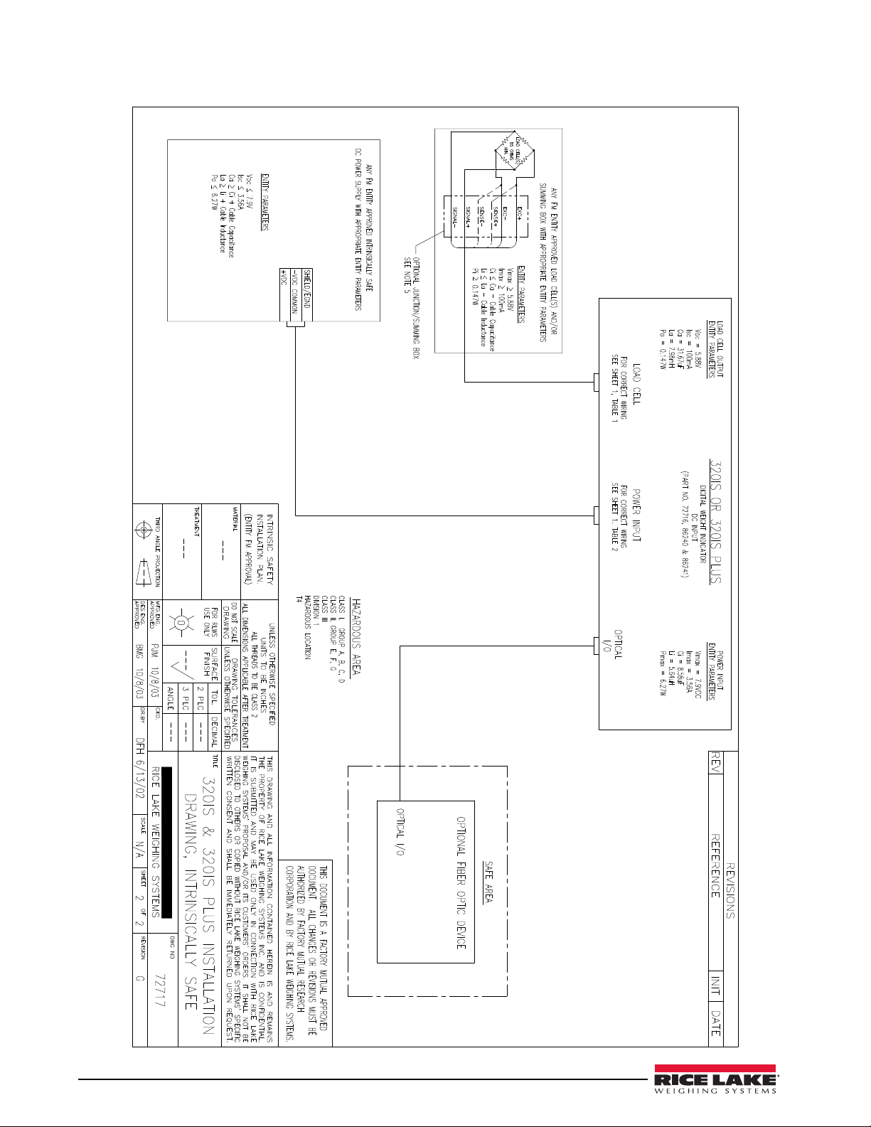
The 320IS Plus is a Factory Mutual-Entity approved component. This approval is valid only if the
installation conforms to the guidelines described in this manual and FM-approved control drawing (PN
way, including field repair or modification, Factory Mutual approval is void, and all warranties, expressed or implied are
void. The customer becomes fully responsible and liable for such modifications.
72717). If modifications are made to the installation procedure, or the instrumentation is changed in any
Manuals can be viewed or downloaded on the Rice Lake Weighing Systems distributor site at
www.ricelake.com.
Safety
Safety Symbol Definitions
Indicates a potentially hazardous situation that, if not avoided, could result in serious injury or death,
and includes hazards that are exposed when guards are removed.
Indicates a potentially hazardous situation that, if not avoided may result in minor or moderate injury.
Indicates information about procedures that, if not observed, could result in damage to equipment or
corruption to and loss of data.
Safety Precautions
Do not operate or work on this equipment unless you have read and understand the instructions and
warnings in this manual. Failure to follow the instructions or heed the warnings could result in injury
or death. Contact any Rice Lake Weighing Systems dealer for replacement manuals. Proper care is
your responsibility.
General Safety
Failure to heed may result in serious injury or death.
Some procedures described in this manual require work inside the indicator enclosure. These procedures are to be
performed by qualified service personnel only. Improper specification, installation, or service of this equipment could
result in personal injury or property damage.
DO NOT allow minors (children) or inexperienced persons to operate this unit.
DO NOT use for purposes other than weight taking.
DO NOT operate indicator without enclosure fully assembled.
DO NOT use this product if any of the components are cracked.
DO NOT exceed the rated load limit of the unit.
DO NOT make alterations or modifications to the unit.
DO NOT remove or obscure warning labels.
DO NOT submerge.
Before opening the unit, ensure the power cord is disconnected from the unit.
The non-metallic parts are considered to constitute an electrostatic discharge hazard. Clean only with a damp cloth.
Substitution of components may impair intrinsic safety.
To prevent ignition of flammable or combustible atmospheres, disconnect power before servicing.
320IS Plus Installation Manual - Introduction 1
Page 8

1. 1 O ve r vi e w
WARNING
The 320IS Plus is a single-channel digital weight indicator designed and approved to operate as an intrinsically
safe system in a wide variety of scale and weighing applications. The indicator is housed in a NEMA 4X/
IP66-rated stainless steel sealed case. The standard unit is equipped with a tilt stand base for tabletop or wall
mounting applications. The indicator front panel consists of a large (0.8 in, 20 mm, 16-segment), six-digit LED
display, 24-button keypad and eight LED annunciators. Features include:
• Drives up to four 350or eight 700 load cells
• Supports four- and six-wire load cell connections (six-wire remote sense recommended)
• Full-duplex fiber optic interface to attach an external I/O board located in the safe area
The 320IS Plus is NTEP-certified and pending Measurement Canada approval for Classes I, II and III at 10,000
divisions.
See Section 9.9 on page 80 for detailed specifications.
Available with optional I/O Module (PN 72721):
• Four configurable digital inputs
• Four digitally-controlled single pole single throw-normally open non-latching relay contact outputs
• Electronic data processing (EDP) port communications at up to 38400 bps for full duplex RS-232/
RS-422/RS-485 and Current loop
• Printer port communications at up to 38400 bps for full duplex RS-232/RS-422/RS-485 and Current loop
• Two 16–bit analog output channels provide ±10V or ±5V, 0-5V or 0-10V, and 4-20 mA tracking of
gross or net weight values
1.2 Factory Mutual Approval
The 320IS Plus is Factory Mutual (FM) Entity approved for:
• Classes I, II, and III
• Divisions 1 and 2
• Groups A, B, C, D, E, F and G
• T-rating T4
Only devices that have FM Entity Approval with proper entity parameters may be used unless specifically listed
in this manual or control drawing PN 72717 as part of the Rice Lake Factory Mutual systems approval. Failure to
comply with this voids the FM approval.
The classification of hazardous materials are different in the US and European standards. Because of this, the
safety class of the
• US standards: Class I, II, III, DIV1, Groups A-G
320IS Plus is declared in the following regulations:
Substitution of components may impair intrinsic safety.
To prevent ignition of flammable or combustible atmospheres, disconnect power before servicing.
1.3 Operating Modes
The 320IS Plus has three modes of operation.
Normal (Primary) Mode
Normal mode is the default mode of the indicator. The indicator displays gross or net weights as indicated by
LED annunciators (see
Setup Mode
Most of the procedures described in this manual require the indicator to be in setup mode including configuration
and calibration.
To enter setup mode, remove the large fillister head screw from the enclosure backplate. Insert a non-metal
screwdriver or a similar tool into the access hole and press the setup switch once. The indicator display changes
to show the word
2 320IS Plus Installation Manual
Figure 1-1) to indicate scale status and the type of weight value displayed.
CONFIG.
Page 9
Test Mo de
Test mode provides a number of diagnostic functions for the 320IS Plus indicator. Like setup mode, test mode is
entered using the setup switch (
Section 8.8 on page 70).
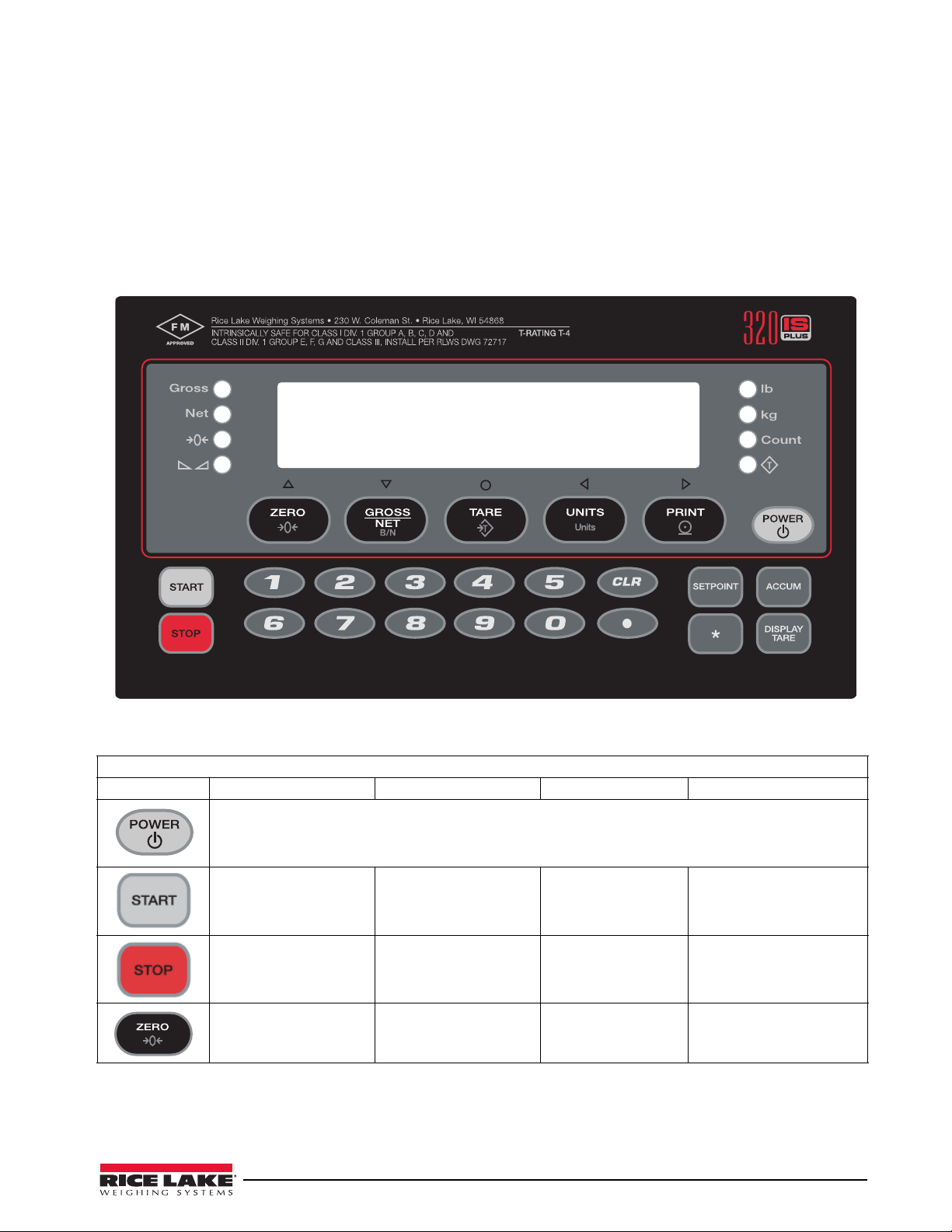
1.4 Front Panel Keypad
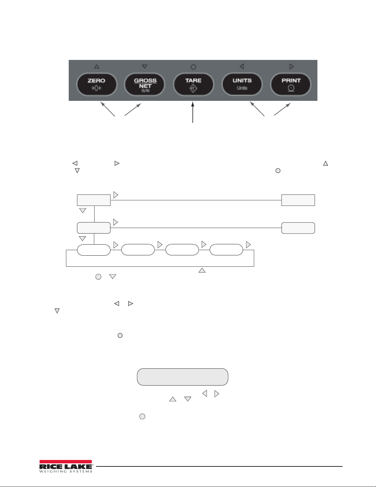
Figure 1-1 shows the 320IS Plus LED annunciators and keypad.
The symbols shown above the keys (representing up, down, enter, left, right) describe the key functions. In setup
mode, the keys are used to navigate through menus, select digits within numeric values, and increment/
decrement values. See
Section 1.5 on page 5 for information about using the front panel keys in setup mode.
Figure 1-1. 320IS Plus Front Panel
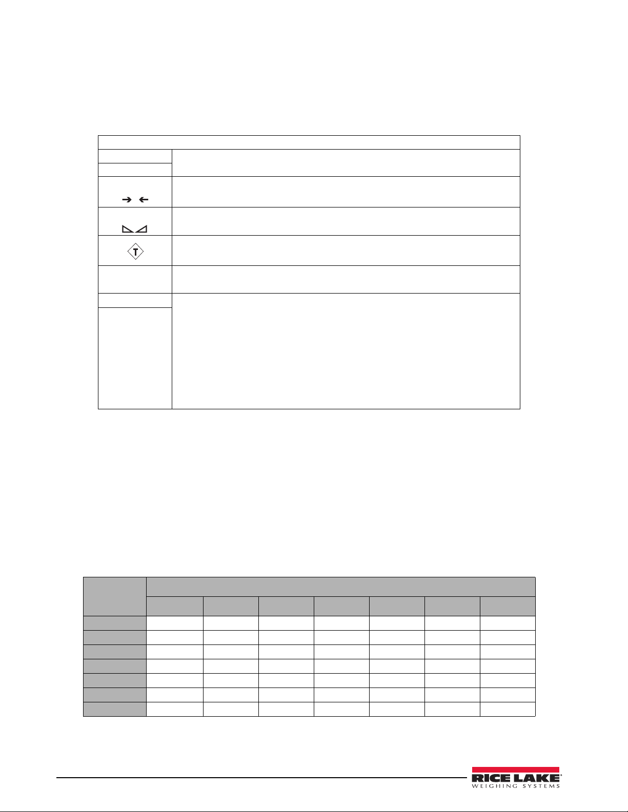
Key Functions
Normal Setup Te st Count
Turn the indicator on or off
Batch start N/A N/A N/A
Batch stop N/A N/A N/A
Return gross weight
display to zero
• Move up (vertically)
• Increment value
• Exit (top level only)
Table 1-1. Indicator Display Key Functions
Exit N/A
320IS Plus Installation Manual - Introduction 3
Page 10
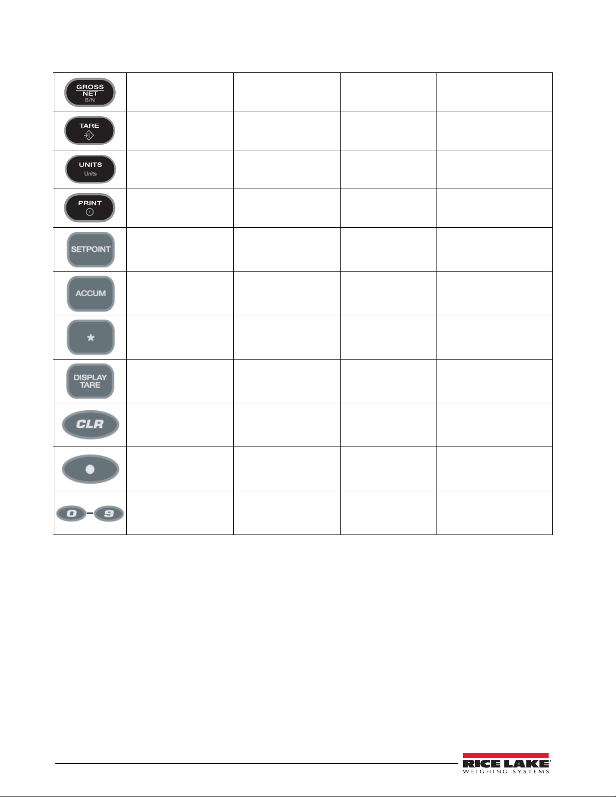
Toggle between gross,
net and piece count
mode
• Move down (vertically)
• Decrement value
N/A Toggle between gross, net
and piece count mode
Press to enter an auto
tare or keyed tare
Toggle between primary
and secondary units
Print using GFMT Move right (horizontally) Print Print using CFMT
• Turn on/off a setpoint
• View a setpoint
• Edit a setpoint
Display the current
accumulator value
Time and date entry N/A N/A N/A
Display the tare value N/A N/A Display the average piece
Clear the displayed value Clear the displayed value N/A N/A
Enter Enter Perform a piece count
• Move left (horizontally)
• Previous
N/A N/A N/A
N/A N/A N/A
Move left (horizontally) Select a sample size
weight
Enter a decimal point Enter a decimal point N/A N/A
Enter a numeric
parameter value
Enter a numeric
parameter value
N/A Enter a sample size
Table 1-1. Indicator Display Key Functions
4 320IS Plus Installation Manual
Page 11
1. 5 Front Panel Configuration
Move Up and
Down (vertically)
Enter
Move Left and
Right (horizontally)
1
st
Level
Parameter
Default value
2
nd
Level
Parameter
Value Value
1
st
Level
Parameter
2
nd
Level
Parameter
When moving thr ough values below the first menu level, press to r etur n to the level
above. Pr ess or to move to the next parameter on the level above.
Value
When editing numeric values, press or to change th e
digit selected. Press or to incr ement or decrement the
value of t he selected digit, or use t he numeric keypad.
Pr ess to save the value entered and return to the level above.
0 0 0 0 0 0
Figure 1-2. Front Panel Key Functions in Setup Mode
Four front panel keys are used as directional keys to navigate through the menus in setup mode (see Figure 1-2).
The UNITS ( ) and PRINT ( ) keys scroll left and right (horizontally) on the same menu level; ZERO ( ) and
GROSS/NET ( ) move up and down (vertically) to different menu levels. The TARE key ( ) serves as an enter key
for selecting parameter values within the menus. A label above each of these keys identifies the direction
provided by the key when navigating through the setup menus.
To select a parameter, press or to scroll left or right until the desired menu group appears on the display, then
press to move down to the submenu or parameter you want. When moving through the menu parameters, the
default or previously selected value appears first on the display.
To change a parameter value, scroll left or right to view the values for that parameter. When the desired value
appears on the display, press
to select the value and move back up one level. To edit numerical values, use the
navigation keys to select the digit and to increment or decrement the value or use the numeric keypad (see
Figure 1-4).
Figure 1-4. Editing Procedure for Numeric Values
Figure 1-3. Setup Mode Menu Navigation
320IS Plus Installation Manual - Introduction 5
Page 12
1.6 LED Annunciators
0
The 320IS Plus display uses eight LED annunciators to provide additional information about the value being
displayed (see
Table 1-3 shows which annunciators are used for all combinations of configured primary and secondary units.
For example:
• If the primary unit is pounds (lb) and the secondary unit is kilograms (kg), the lb LED is lit for primary
• If the primary unit is pounds (lb) and the secondary unit is short tons (tn), the lb LED is lit for primary
• If the primary unit is short tons (tn) and the secondary unit is pounds (lb), the lb LED is lit for primary
See Section 3.2.2 on page 25 for more information about configuring primary and secondary display units.
Figure 1-1 on page 3):
LED Annunciators
Gross
Net
Center of Zero Gross weight is ±0.25 graduations of zero. This annunciator lights when the scale is
Standstill Scale is at standstill or within the specified motion band. Some operations, including
Count The Count annunciator is lit to show that the indicator is in piece count mode.
0 lb lb and kg annunciators indicate the units associated with the displayed value:
0kg
The Gross and Net annunciators are lit to show whether the displayed weight is a
gross or net weight.
.
zeroed
tare functions and printing, can only be done when the standstill symbol is shown.
The Tare Acquired light shows that a tare value has been entered.
lb=pounds, kg=kilograms. Two units of measurement can be chosen to toggle
between.
The displayed units can also be set to ounces (oz), short tons (tn), metric tons (t),
grams (g), or they can be disabled. A user-defined unit can also be set as secondary
unit by declaring a conversion factor in the setup menu. The
as primary and secondary units annunciators for some combinations of primary and
secondary units. If neither primary nor secondary units are lb, kg, oz, or g, the
annunciator is lit for primary units, kg for secondary units.
lb and kg LED’s function
lb
Table 1-2. LED Annunciators
units, kg for secondary units.
kg for secondary units. There is no LED for short tons, so the kg LED is used as the secondary units
units,
annunciator.
units (tn), and
kg is lit for secondary units (lb). Because there is no LED for short tons, the lb and kg LEDs
are used as primary and secondary units annunciators.
Secondary Unit
Primary Unit
lb lb / lb lb / kg lb / kg lb / kg lb / kg lb / kg lb / kg
kg kg / lb kg / kg kg / lb kg / lb kg / lb kg / lb kg / lb
oz kg / lb lb / kg lb / kg lb / kg lb / kg lb / kg lb / kg
tn kg / lb lb / kg lb / kg lb / kg lb / kg lb / kg lb / kg
t kg / lb lb / kg lb / kg lb / kg lb / kg lb / kg lb / kg
g kg / lb lb / kg lb / kg lb / kg lb / kg lb / kg lb / kg
none kg / lb lb / kg lb / kg lb / kg lb / kg lb / kg lb / kg
lb kg oz tn t g none
Table 1-3. Unit Annunciators, Primary/Secondary LEDs Used For All Configurations
6 320IS Plus Installation Manual
Page 13

1.7 Indicator Operations
Note
Basic 320IS Plus operations are summarized below.
1.7.1 Toggle Gross/Net Mode
Press the GROSS/NET key to switch the display mode from gross to net, or from net to gross. If a tare value has
been entered or acquired, the net value is the gross weight minus the tare. The
Tare( ) annunciator is lit when
a tare value is currently stored in memory.
1.7.2 Toggle Units
Press the UNITS key to switch between primary and secondary units. The appropriate units LED to the right of the
display is lit.
1.7.3 Zero Scale
1. In gross mode, remove all weight from the scale and wait for .
2. Press the ZERO key. annunciator lights to indicate the scale is zeroed.
1.7.4 Acquire Tare
0
1. Place container on scale.
2.
When is lit
, press the
TARE
. The indicator switches to net mode.
3. To display the current tare value, press the DISPLAY TARE .
1.7.5 Remove Stored Tare Value
1. Remove all weight from the scale and wait for ( ).
2. When is lit
, press the
TARE
. The indicator switches to
gross mode, indicating the tare value has been
removed.
1.7.6 Alternate Method to Remove Tare
1. In gross mode, press Display Tare.
2. Press CLEAR.
3. Display shows CLRTAR.
4. Press CLEAR. Indicator switches to gross mode. Inactive tare value has been removed.
1.7.7 Acquire Parts Sample
1. Place empty parts container on scale.
2. Press TA RE to acquire the tare weight of the container.
3. Press GROSS/NET to enter piece count mode.
Press the CLEAR key to exit.
4. Press the UNITS key to enter sample acquisition mode.
Addnnn displays, nnn is the sample quantity to be placed on the scale.
• Add the number of parts shown.
• Choose a different sample size. Press the SAMPLE key to scroll through the selectable sample quantities
(5, 10, 20, 50, 100) or use the numeric keypad to specify a custom sample size.
• Specify a known piece weight. Press the SAMPLE key to scroll through the selectable sample quantities
until the
PC WGT prompt is shown. Use the numeric keypad to enter the piece weight.
5. Once the sample quantity is on the scale, press ENTER to calibrate the indicator for counting the new
parts.
6. If a sample size was specified, the indicator display shows the message –CNT– as it acquires the sample
weight, then switches to count display mode and shows the part quantity.
7. If a known piece weight was specified, the display switches to count display mode immediately.
320IS Plus Installation Manual - Introduction 7
Page 14

1.7.8 Display Part Weight
Note
Note
Note
To view gross and net weight parts, press MODE to switch from count display mode to normal weighing mode.
To view the current piece weight while in count mode, press DISPLAY TARE key.
1.7.9 Display or Change Time/Date
Requires optional I/O Module (PN 72721).
To display the date, press the asterisk (*) key once; press asterisk (*) a second time to display the time.
To set the date, press the asterisk (*) key once. Use the numeric keypad to enter the date, then press the ENTER key.
Use the numeric keypad to enter the date in the same format configured for the indicator: MMDDYY, DDMMYY,
or YYMMDD.
To set the time, press the asterisk (*) key twice. Use the numeric keypad to enter the time in 24-hour format, then
press the
1.7.10 Print Ticket
ENTER key.
Requires optional I/O Module (PN 72721).
Wait for the standstill annunciator ( ). Press the PRINT key to send data to the serial port. Standstill must be
lit to print.
1.7.11 Display or Change Setpoint Value
To display a setpoint value, press the SETPOINT key. To change the setpoint value, display the current value, then
use the numeric keypad to enter the new value and press the
ENTER key.
1.7.12 Turn Setpoint On or Off
Requires optional I/O Module (PN 72721).
To turn a setpoint off at the front panel. With the correct setpoint displayed, press CLEAR to turn the setpoint off.
To re-enable a setpoint that has been turned off at the front panel, press the SETPOINT key, then press ENTER to
turn the setpoint back on.
1.7.13 Display or Clear Accumulator
If the accumulator function is enabled, the current net weight is added to the accumulator each time the indicator
performs a print operation.
• To display the current accumulator value, press the ACCUM key.
• To clear the accumulator, press ACCUM to show the current value, then press the CLEAR key twice to
reset the accumulator.
8 320IS Plus Installation Manual
Page 15

2.0 Installation
CAUTION
Important
WARNING
This section describes installation of load cells, power supply, fiber optics, and ferrite bead for the 320IS Plus
indicator.
Use a wrist strap to ground yourself and protect components from electrostatic discharge (ESD) when
working inside the indicator enclosure.
Component level repair, excluding board-swapping, is not permitted on Factory Mutual Approved
equipment by anyone other than the manufacturer. It is mandatory to return the 320IS Plus to Rice
Lake Weighing Systems for repairs.
2.1 Unpacking and Assembly
Immediately after unpacking, visually inspect the 320IS Plus to ensure all components are included and
undamaged. The shipping carton should contain the indicator with attached tilt stand, this manual, and a parts kit.
If any parts are missing or were damaged in shipment, notify Rice Lake Weighing Systems and the shipper
immediately. See
2.2 Enclosure Disassembly
The indicator enclosure must be opened to connect cables for load cells, communications, and power.
1. Ensure power to the indicator is disconnected.
2. Place the indicator face-down on an antistatic work mat.
3. Remove the screws that hold the backplate to the enclosure body.
4. Lift the backplate away from the enclosure and set it aside.
Table 2-5 on page 18 for parts kit.
Before opening the unit, ensure the power is disconnected from the power outlet.
320IS Plus Installation Manual - Installation 9
Page 16
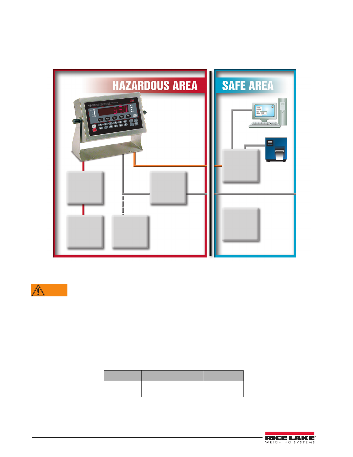
2.3 Hazardous Area Installation of the 320IS Plus
Junction
Box
(Optional)
AC Power
Supply
(Intrinsically
Safe Output)
FM-Approved
Load Cells
(up to 4–350Ω)
Battery
(Optional)
I/O Module
(Optional)
Battery
Charger
(Optional)
Load Cell
Input
Fiber Optic
VDC 115/230VAC
WARNING
The following information is provided to help the installer with the correct installation of the 320IS Plus system.
Figure 2-1 below for a diagram of a typical intrinsically safe system.
See
2.3.1 Power Supply to Indicator
The indicator should be powered by an FM-approved Rice Lake power supply or alternatively from an external
battery pack. The power requirements of the
The DC power cable should be attached to connector CN1 (see Table 2-1). Care must be taken to wire CN1 with
the correct DC polarity. See Section 2.4 on page 11 for information on cabling through metal cord grips.
10 320IS Plus Installation Manual
Figure 2-1. Intrinsically Safe System Diagram
Do not, under any circumstances, connect or disconnect the DC wire from the indicator while the AC
power is applied to the power supply. This will cause the power supply fuse to blow.
320IS Plus are as follows:
• Minimum input voltage: 5.8 V
• Maximum input voltage: 7.9 V
• Peak current consumption: 190 mA
• Average input current (with four load cells): 140 mA
CN1 Pin Function Wire Color
1 + Voltage (5.8 – 7.9 V) Green
2 Ground (V–, Common) Brown
Table 2-1. DC Power Supply Connections
Page 17
A separate conduit system is recommended for installation. The type suggested for this application is 3/4" rigid
Note
Note
Note
steel conduit with pull boxes located at required intervals. The conduit provides additional noise protection for
the low-level signals, while automatically complying with the requirements for two-inch separation between
intrinsically safe circuits and other electrical cables. Conduit seals are necessary where a gas tight seal is required
between hazardous area and safe area.
2.3.2 AC Power Wiring
Standard units are powered by an FM-approved power supply. 100–240 VAC into RLWS IS-EPS-100-240
Intrinsically safe DC output power supply (PN 72713) is recommended.
See the IS-EPS-100-240 Power Supply Instruction Sheet (PN 79820) for information on wiring and power
specifications.
2.3.3 Battery Option
The optional battery pack provides an intrinsically safe battery that can replace the power supply. The battery is
approved for use in hazardous environments and limited use operations such as bench scales and platform scales.
A low battery error message will display to indicate that the battery needs to be recharged. Always charge the
battery overnight. The yellow indicator light will remain on until the battery is charged at about 70%, at which
point the indicator light will turn green and the charger will switch to float charge mode. Once the light turns
green, the battery requires another 3 hours on float charge before the battery is fully charged.
To keep battery at full capacity, it is recommended to leave the battery connected to the charger, in float
charge mode, until ready to use. The battery can remain on the charger in float charge mode indefinitely
without damaging the battery. See Battery Charging Instruction Sheet (PN 96567) for instructions on
charging the battery.
Load Cell Size Quantity of cells Operating Time
350 load cell 1 40 - 50 hours
4 35 - 40 hours
700 load cell 1 45 - 55 hours
4 40 - 50 hours
Table 2-2. Estimated Battery Operating Times
While connected to the DC battery pack with the indicator off, the 320IS still draws a small amount of
current that will shorten battery run time. To preserve battery life, disconnect the battery when not in use.
2.4 Cable Connections and Installation
The following sections contain information on cable connections and installation for the 320IS Plus.
Intrinsically safe cables are specified by control drawing. All cables must have appropriate internal
inductance and capacitance. Cable lengths are based on group classifications.
Figure 2-2. Metal Cord Grip
320IS Plus Installation Manual - Installation 11
Page 18

Before connecting the AC power to the power supply:
WARNING
Note
1. Determine the length of AC power cord necessary to reach from the AC power panel to the power supply
where it is mounted.
2. Cut the AC power cord to that length. If you are mounting the I.S. power supply in a hazardous area, all
AC power must be routed through approved conduit, where necessary make allowances in length of the
conduit.
3. Install the AC power cord but do not hook up to the AC power.
Do not, under any circumstances, connect or disconnect the DC wire from the indicator while the AC
power is applied to the power supply. This will cause the power supply fuse to blow.
4. Determine the length of the DC power cord necessary to reach from the AC power supply to the 320IS
Plus indicator and add 7" to that length.
5. Cut the DC power cord to that length.
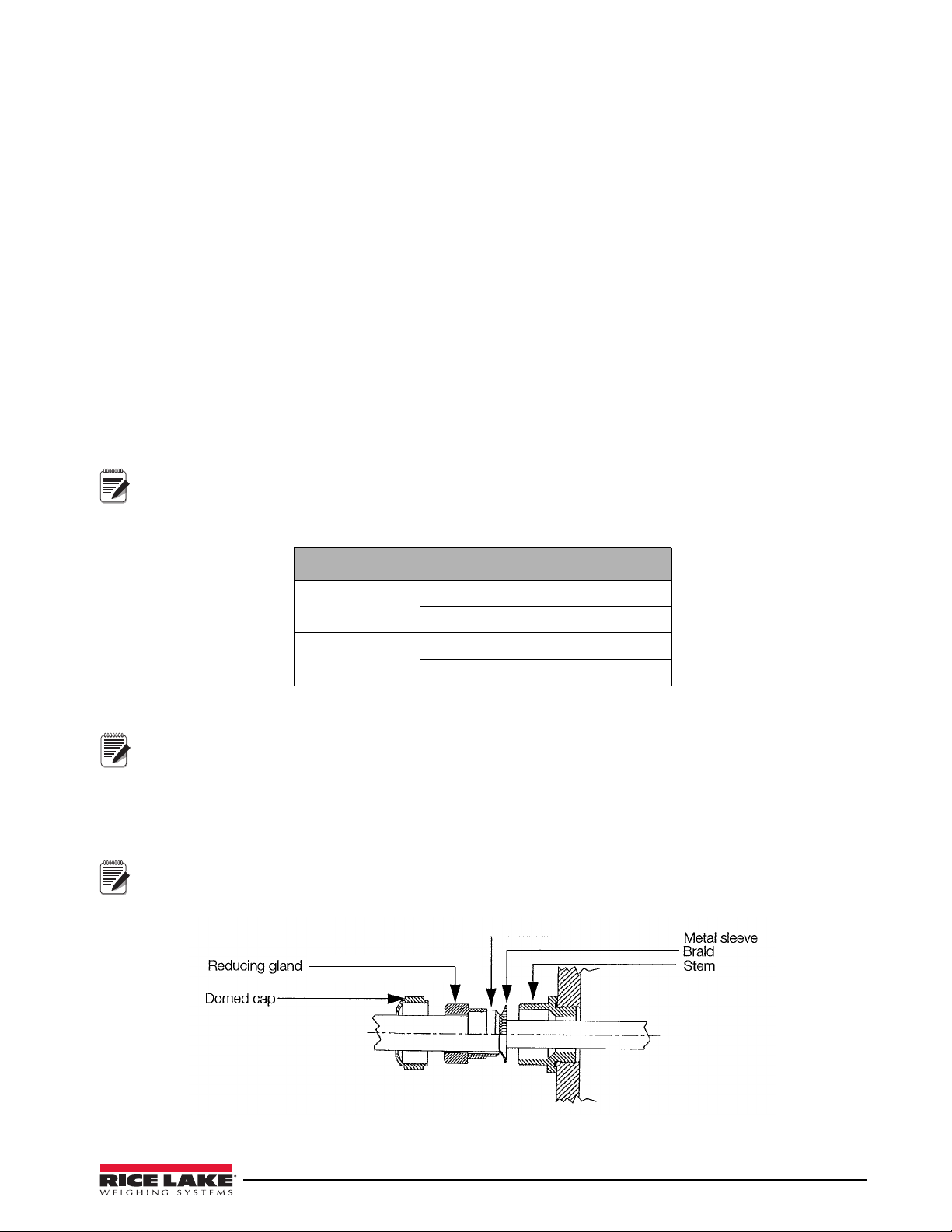
2.4.1 Braided Power Cable Connection with Ferrite Core
Use the following procedure for connecting braided power cable with the ferrite core:
1. If using the ferrite core, carefully remove 7" of the outer blue insulation and 6.5" of braid from the cable.
If not using the ferrite core, go to Section 2.4.2.
2. Remove the reducing gland and metal sleeve from the center cord grip of the indicator. Place them on a
work surface.
3. Remove the cap and reducing gland from the 320IS Plus parts kit.
The cap and reducing gland from the parts kit have larger holes. DO NOT confuse these parts with the
parts removed from the cord grip of the indicator.
4. Take the metal sleeve (from step 2) and insert it into the reducing gland taken from the parts kit.
5. Place the domed cap and reducing gland that were removed from the 320IS cord grip, into the parts kit
(to be used as spares).
6. Thread the DC cable through the domed cap, then through the reducing gland/metal sleeve combination.
7. Lower the reducing gland assembly so that the end of the metal sleeve is at the edge of the insulation and
fold the braid over the metal sleeve (
Figure 2-2). Trim the braid if necessary.
8. Trim the white wire back to match the end of the braid.
9. Tin the green and brown wire ends.
10. Thread the cable through the cord grip stem.
12 320IS Plus Installation Manual
Chassis ground is made through the braid compressed between the metal sleeve and the cord grip stem.
11. Lower the domed cap onto the cord grip stem and tighten until a small swelling of the rubber of the
reducing gland appears between the domed cap and cable (see
Figure 2-3. Proper Cord Grip Compression
Figure 2-3).
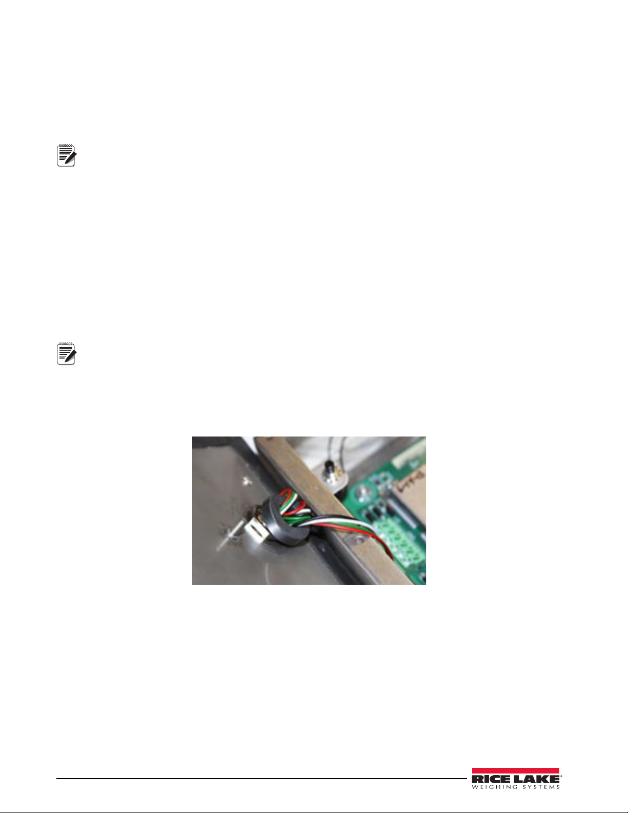
Page 19
12. Thread the green and brown wires two times through the ferrite core from the parts kit. See Figure 2-4 as
Note
Note
Note
an example picture.
13. Connect the green and brown wires to the connector for CN1, observing polarities. See Table 2-3 below.
CN Pin 1 Function Color
1 + Voltage (5.8 - 7.9) Green
2 Ground (V-, Common) Brown
Table 2-3. DC Power Supply Connections — CN1
14. Plug the connector onto CN1.
15. Connect the AC power.
2.4.2 Braided Power Cable Connection Without Ferrite Core
Use the following procedure for connecting a braided power cable without a ferrite core.
1. If not using a ferrite core, carefully remove 3" of outer blue insulation and 2.5" of braid from the cable.
2. Remove the domed cap, reducing gland and the metal sleeve from the center cord grip of the indicator.
Place them on a work surface.
3. Remove the domed cap and reducing gland from the 320IS Plus parts kit.
The domed cap and reducing gland from the parts kit have larger holes. DO NOT confuse these parts with
the parts removed from the cord grip.
4. Take the metal sleeve (from step 2) and insert it into the reducing gland taken from the parts kit.
5. Place the domed cap and reducing gland that were removed from the 320IS cord grip, into the parts kit
(to be used as spares).
6. Thread the DC cable through the domed cap, then through the reducing gland/metal sleeve combination.
7. Lower the reducing gland assembly so that the end of the metal sleeve is at the edge of the insulation and
fold the braid over the metal sleeve (Figure 2-2). Trim the braid if necessary.
8. Trim the white wire back to match the end of the braid.
9. Tin the end of the green and brown wires.
10. Thread the cable through the cord grip stem.
Chassis ground is made through the braid compressed between the metal sleeve and the cord grip stem.
11. Lower the domed cap onto the cord grip stem and tighten until a small swelling of the rubber of the
reducing gland appears between the domed cap and cable (see Figure 2-3).
12. Connect the green and brown wires to the connector for CN1. Observe polarity. See Table 2-3.
13. Plug the cable into CN1.
14. Connect the AC power.
2.4.3 Braided Load Cell Cable Connection
Use the following procedure for connecting braided load cell cable:
If Using 6 Wire Load Cell Cable
1. Carefully remove 8" of outside insulation and 7 1/2" of braid from the load cell cable.
2. Remove the metal domed cap, reducing gland and metal sleeve from the left metal cord grip. Place them
on a work surface.
3. Remove the reducing gland and metal domed cap from the 320IS plus parts kit.
These have a larger hole than those removed from the cord grip — DO NOT confuse them.
4. Take the metal sleeve from step 2, and insert it into the reducing gland taken from the parts kit.
5. Retain the cord grips.
320IS Plus Installation Manual - Installation 13
Page 20
6. Thread the load cell cable through the domed cap, then through the reducing gland/metal sleeve
Note
Note
assembly.
7. Lower the reducing gland assembly so that the end of the metal sleeve is at the edge of the insulation and
fold the braid back over the sleeve (see
Figure 2-2). Trim if necessary.
8. Thread the cable through the cord grip stem.
Chassis ground is made through the braid compressed between the metal sleeve and the cord grip stem.
9. Lower the domed cap onto the cord grip stem and tighten until a small swelling of the rubber of the
reducing gland appears between the dome cap and the cable (see
Figure 2-3).
10. Thread the load cell cable through the ferrite core, from the parts kit, twice. Keep the ferrite core as close
to the backplate as possible (see Figure 2-4).
If Using 4 Wire Load Cell Cable
1. Carefully remove 8" of outside insulation and 7 1/2" of braid from the load cell cable.
2. Remove the metal domed cap and reducing gland from cord grip, place them on a work surface.
3. Thread the load cell cable through the domed cap, then through the reducing gland/metal sleeve
assembly.
4. Lower the reducing gland assembly so that the end of the metal sleeve is at the edge of the insulation and
fold the braid back over the sleeve (see Figure 2-2). Trim if necessary.
5. Thread the cable through the cord grip stem.
Chassis ground is made through the braid compressed between the metal sleeve and the cord grip stem.
6. Lower the domed cap onto the cord grip stem and tighten until a small swelling of the rubber of the
reducing gland appears between the domed cap and the cable (see Figure 2-3).
7. Thread the load cell cable through the ferrite core, from the parts kit, twice. Keep the ferrite core as close
to the backplate as possible (see Figure 2-4).
Figure 2-4. Ferrite Core Wire Wrap
2.4.4 Foil Load Cell Cable Connection
Use the following procedure for connecting foil load cell cable:
1. Carefully remove 8" of insulation and 7 1/2" of foil from cable.
2. Remove domed cap, reducing gland and metal sleeve from cord grip and place them on the cable (see
Figure 2-2).
3. Thread the load cell cable through the domed cap, then through the reducing gland metal sleeve
assembly.
4. Lower reducing gland metal sleeve assembly to edge of insulation and wrap foil over metal sleeve of
reducing gland leaving the silver side out.
5. Thread the cable through the cord grip stem.
14 320IS Plus Installation Manual
Page 21
Chassis ground is made through the foil compressed between the metal sleeve and the cord grip stem.
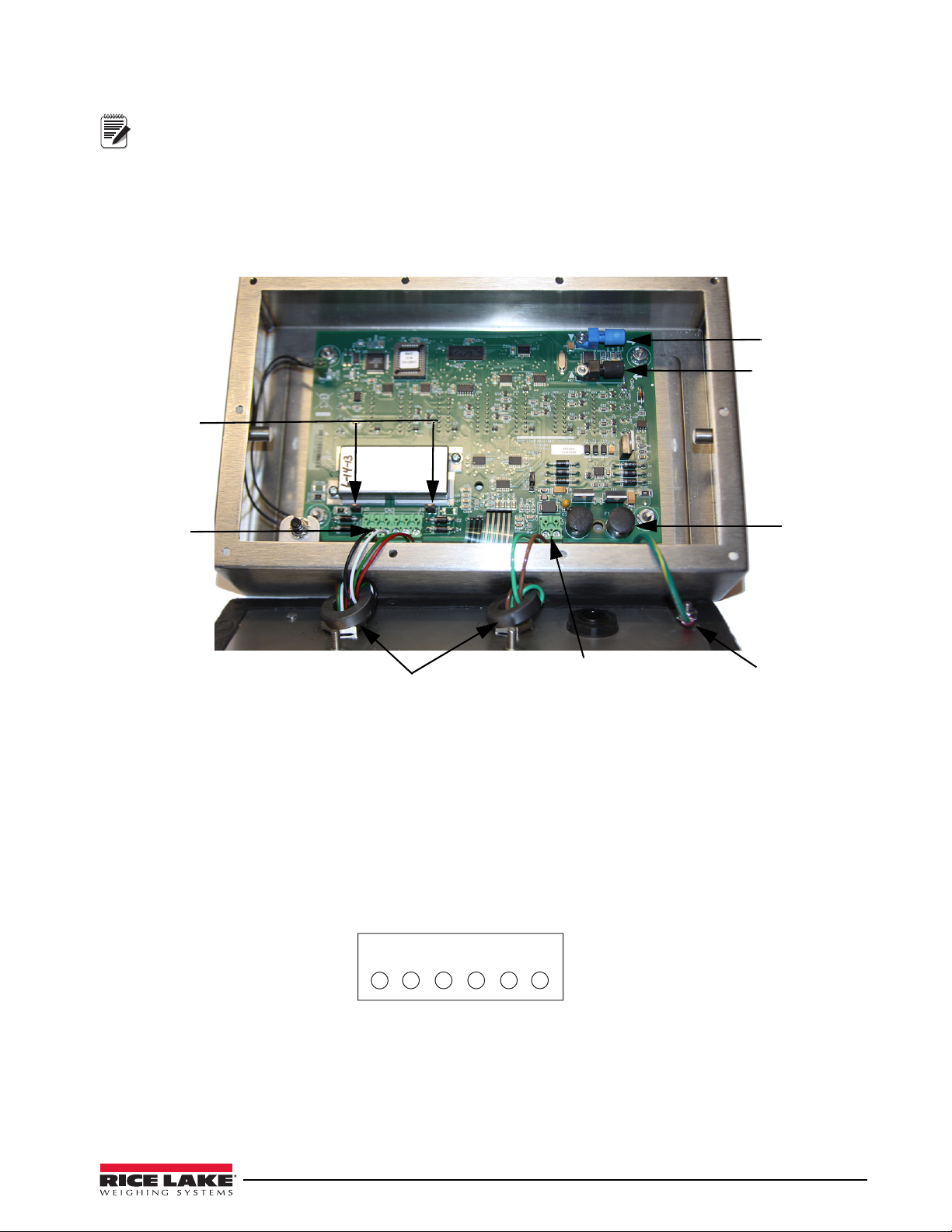
Note
Load cell
connector
Power cable connector
Green = +Voltage
Brown = Return
125mA fully –
encapsulated
fuses
F1 & F2
Blue opptical
output
Black optical
input
Ferrite cores
Chassis
ground
Sense jumpers
J1 & J2
1 2 3 4 5 6
CN3
-Excitation
-Sense
-Signal
+Signal
+Sense
+Excitation
6. Lower the domed cap onto cord grip stem.
7. Tighten until a small swelling of the rubber between the domed cap and the cable builds (see Figure 2-3).
8. Thread wires through ferrite core two times. Keep the ferrite as close to the backplate as possible (see
Figure 2-4).
9. Wire cable to connector CN3.
2.4.5 Load Cells
To attach cable from a load cell or junction box, use six-position connector in parts kit. See Section 2.4 on
page 11 for information on cabling through metal cord grips.
Wire the load cell cable from the load cell or junction box to connector CN3 as shown in Figure 2-6. If using
6-wire load cell cable (with sense wires), remove jumpers J1 and J2 before installing connector CN3. For
four-wire installation, leave jumpers J1 and J2 on.
When connections are complete, reinstall connector CN3 on the board and use two cable ties to secure the load
cell cable to the inside of the enclosure.
Figure 2-5. Cable Connections
Figure 2-6. CN3 Load Cell Connections
320IS Plus Installation Manual - Installation 15
Page 22
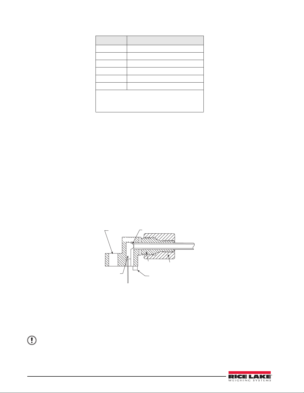
Pin Function
Optical Fiber
Locking Nut
Positioning Foot
Housing
Lens
Mounting Hol e
Device
LED
Important
1 -Excitation
2 -Sense
3 -Signal
4 +Signal
5 +Sense
6 +Excitation
• For six-wire connections, remove jumpers J1 and
J2.
• For four-wire connections, leave jumpers J1 and
J2 on.
Table 2-4. CN3 Pin Assignments
2.5 Fiber Optics Installation
The 320IS Plus is equipped with a duplex fiber optic port for communicating with an I/O Module located outside
the hazardous area. This is the only communications channel of the indicator. The indicator communicates with
external devices through the optional I/O Module’s physical interfaces (RS–232, RS–422, RS–485, Current
Loop) and provides analog and digital I/O functions such as setpoint relays and analog outputs.
The fiber optics port is located on the indicator CPU board (see Figure 2-5).
2.5.1 Assembling Fiber Optics Connectors
Use the following steps for assembling the fiber optic connectors of the 320IS Plus:
1. Cut off the ends of the fiber optic cable (PN 74000) with a single-edge razor blade or hot knife (PN
85548). Try to obtain a precise 90º angle.
2. Insert the fiber through the locking nut and into the connector until the core tip seats against the internal
micro-lens.
3. Screw the connector locking nut down to a snug fit, locking the fiber in place.
4. Secure fiber with 3-inch nylon cable ties in parts kit and 3/4-inch square nylon mounts.
Figure 2-7. Fiber Optics Connector
2.6 Enclosure Reassembly
1. Position the backplate over the enclosure.
2. Reinstall the backplate screws. Use the torque pattern shown in Figure 2-8 to prevent distorting the
backplate gasket. Torque screws to 15 in-lb (1.7 N-m).
Torqued screws may become less tight as the gasket is compressed during torque pattern, therefore a
second torque is required using the same pattern and torque value.
16 320IS Plus Installation Manual
Page 23
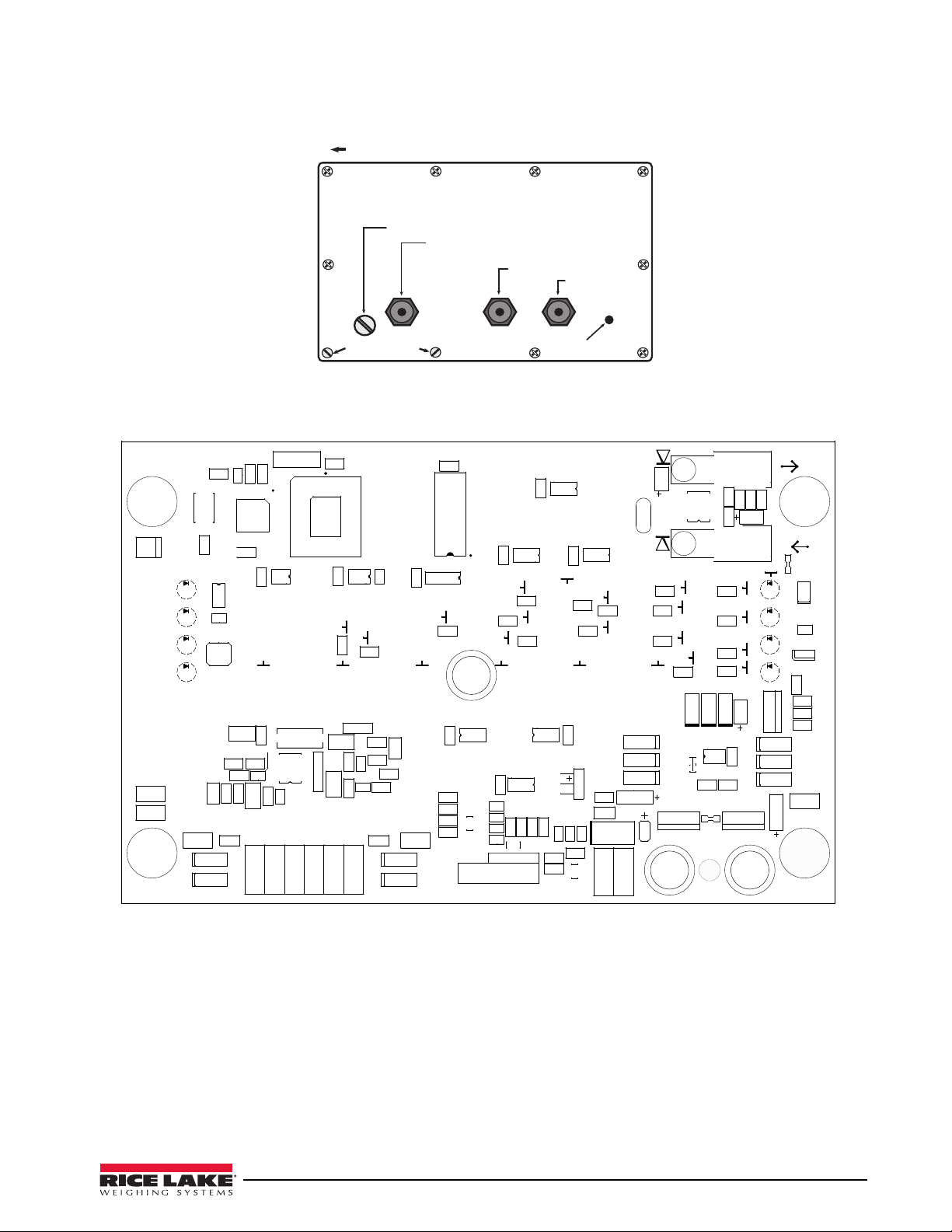
Figure 2-8. 320IS Plus Enclosure Backplate
Setup switch access screw
Fillister head screws
10
9
8
7
4
3
1
2
5
6
Torque pattern
Load cell connection cord grip
DC power cord grip
Fiber optics
cord grip
Ground lug
LH
*4
5
.
0
5
&
;
&
3
4&561
P[
H
MC
%4
%4
*4
%4
/
0
3
&
5
"
%4
%4
%4
'
51
$
3
-
9
$
$
3
$
2
$
3
3
3
2
$
$
$
3
$
2
3
$
$
$
3/
$
$
2
3
3
6
3
$
3
$
3
$
3
3
$
;
;
574&(
+
$
3
51
+
$
$
$
-
3
3
3/
3
$
3
3
3
$
-
2
3
3
3
3
3
.&$$"
48
.
%
%
3
$
$
$
$
(/%
%(/%
6
$
$
$
$
$
$
$
3
$
2
2
2
3
6
$
$
$
6
$
6
$
2
3
2
6
$
(/%
$/
$
$
,&:1"%
$
3
2
3
6
9
.&$$"
6
$
2
2
3
3
3
2
2
3
6
2
3
3
$
$
3
6
.
.
6
3
$
3/
$
3
2
2
%
6
6
;
'
2
$
;
.
6
574"(
;
;
;
;
%
%
6
9
3'*&(
3'*"(
3
2
6
+
;
;
6
(&
$
2
2
*'%
1%
2
$
6
3
4* &9&9 4& 4*
4&
$/
6
6
'
2
$
-%
6
$/
$/
0QUJDBM0VUQVU
0QUJDBM*OQVU
1PXFS
$POOFDUPS
-PBE$FMM$POOFDUPS
Figure 2-9. 320IS Plus CPU Board
320IS Plus Installation Manual - Installation 17
Page 24

Part Number Description (Quantity) Part Number Description (Quantity)
45043 4 in. W/No. 8 Ground Wire 14626 8–32NC Hex Kep Nut
16892 Earth Ground Label 19538 1.25 x 1 Slotted Black Post
15627 PG–9 Metal Lock Nut 91852 PG–9 Metal Cord Grip
15626 PG–9 Black Cord Grip 82432 125 mA Encapsulated Time–Lag Fuse
50962 PCN–9 Black Nut 72916 Backplate
45042 SS Bonded Sealing Washer, #8 14862 8–32NC x 3/8 Screw
39037 Backplate Gasket 68216 Rice Lake Nameplate
42640 1/4 – 28NF x 1/4 Screw 44676 Bonded Sealing Washer, 1/4"
29635 SS Tilt Stand 68403 1/4 – 20 Two-Prong Black Knob
15144 1/4 x 1 x 1/16 Nylon Washer
100345 Reconditioned/Exchange 320IS Plus
Table 2-5. Hardware Replacement List
18 320IS Plus Installation Manual
Page 25
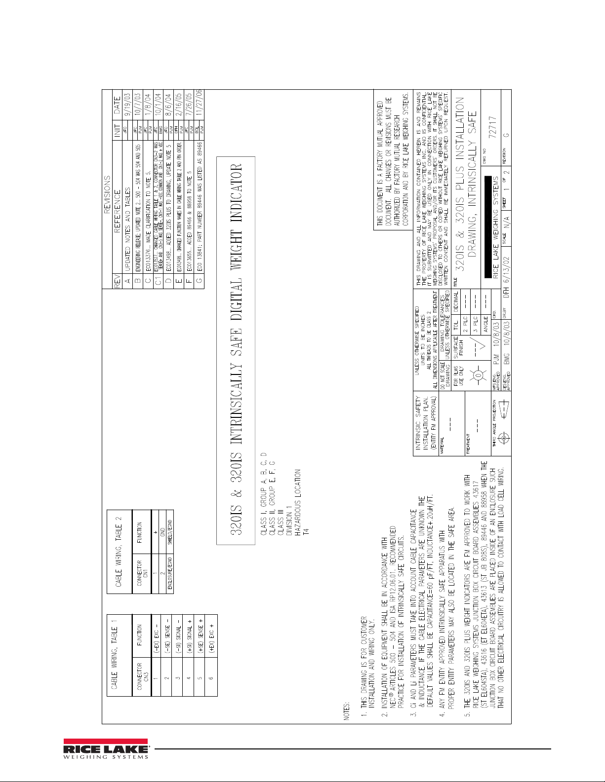
2.7 Control Drawings
320IS Plus Installation Manual - Installation 19
Page 26
20 320IS Plus Installation Manual
Page 27

3.0 Configuration
Note
To configure the 320IS Plus indicator, the indicator must be placed in setup mode. The setup switch is accessed
by removing the large fillister head screw on the enclosure backplate. Setup mode is enabled by inserting a
non-metallic screwdriver into the access hole and pressing the pushbutton configuration switch.
SERIAL, PFORMT, SETPNT, DIGIN, and ALGOUT functions require fiber optics communications with I/O
module in order to operate.
When the indicator is placed in setup mode, the word CONFIG is shown on the display. The CONFIG menu is the
first of nine main menus used to configure the indicator. See
complete, scroll to the CONFIG menu then press the (ZERO) key to exit setup mode. Replace the setup switch
access screw.
3.1 Configuration Methods
The 320IS Plus indicator can be configured by:
• front panel keys (see section 3.2)
• sending commands or configuration data to the EDP port of the optional I/O Module
Configuration using the EDP port can be accomplished using either the EDP command set described in
Section 5.0 on page 44 or the Revolution® configuration software.
3.1.1 Revolution Configuration
The Revolution configuration software is the preferred method for configuring the 320IS Plus indicator.
Download Revolution on a computer to set the configuration parameters for the indicator. When Revolution
configuration is complete, configuration data can be downloaded to the indicator through the optional I/O
Module’s EDP port.
Revolution supports both uploading and downloading of indicator configuration data. This capability allows
configuration data to be retrieved from one indicator, edited, then downloaded to another.
To use Revolution, do the following:
Section 3.2 on page 22. When configuration is
1. Install Revolution on a computer running Windows® 98 or later. Minimum system requirements are
32MB of system RAM (64MB for NT4/2000/XP) and at least 40MB of available hard disk space.
2. With both the I/O Module and indicator powered off, connect the PC serial port to the RS-232 pins on
the I/O Module’s EDP port (See Section 8.0 on page 61 for terminal pin diagrams).
3. Power up the I/O Module and the indicator. Use the setup switch to place the indicator in setup mode.
4. Start the Revolution program.
Revolution provides online help for each of its configuration sections. Parameter descriptions provided in this
manual for front panel configuration can also be used when configuring the indicator using Revolution: the
interface is different, but the parameters are the same.
3.1.2 EDP Command Configuration
The EDP command set can be used to configure the 320IS Plus indicator using a personal computer, terminal, or
remote keyboard. EDP command configuration sends commands to the indicator EDP port; commands can be
sent using any external device capable of sending ASCII characters over a serial connection.
EDP commands duplicate the functions available using the indicator front panel and provide some functions not
otherwise available. EDP commands can be used to simulate pressing front panel keys, to configure the indicator,
or to dump lists of parameter settings. See
command set.
3.1.3 Front Panel Configuration
The 320IS Plus indicator can be configured using a series of menus accessed through the indicator front panel
when the indicator is in setup mode.
Table 3-1 summarizes the functions of each of the main menus.
Section 5.0 on page 44 for more information about using the EDP
320IS Plus Installation Manual - Configuration 21
Page 28

Menu Menu Function
Note
CONFIG Configuration Configure grads, zero tracking, zero range, motion band, overload, tare function, push button
enable, and digital filtering parameters.
FORMAT Format Set format of primary and secondary units, display rate.
CALIBR Calibration Calibrate indicator. See Section 4.0 on page 41 for calibration procedures.
SERIAL Serial Configure EDP and printer serial ports.
PROGRM Program Set regulatory mode, unit ID, auto zero, consecutive number values, and battery standby.
PFORMT Print Format Set print format used for gross and net tickets. See Section 6.0 on page 53 for more
information.
SETPNT Setpoints Configure setpoints. See Section 7.0 on page 56 for setpoint configuration.
DIGIN Digital Input Assign digital input functions. See Section Figure 3-12. on page 38 for more information.
ALGOUT Analog Output Configure analog output. See Section 3.2.8 on page 38 for analog output configuration.
VERS Version Display installed software version number.
Table 3-1. 320IS Plus Menu Summary
SERIAL, PFORMT, SETPNT, DIG IN, and ALGOUT menu functions require fiber optics communications with
I/O module to operate.
3.2 Menu Structures and Parameter Descriptions
The following sections provide graphic representations of the 320IS Plus menu structures. In the actual menu
structure, the settings you choose under each parameter are arranged horizontally. To save page space, menu
choices are shown in vertical columns. The factory default setting appears at the top of each column.
Most menu diagrams are accompanied by a table that describes all parameters and parameter values associated
with that menu. Default parameter values are shown in bold type.
To exit configuration mode, with the display showing CONFIG., press the ZERO key to scroll up.
22 320IS Plus Installation Manual
Page 29

3.2.1 Configuration Menu
XXXXXXX XXXXXXX
XXXXXXX XXXXXXX
GRADS
10 000
OFF
1D
0.5D
3D
ZTRKBN ZRANGE
1.9%
100%
OFF
2D
1D
3D
MOTBAN
5D
FS+2%
FS+9D
FS+1D
FS
OVRLOA
number
BOTH
PBTARE
NOT ARE
KEYED
T AREFN
VERS ALGOUT DIG IN
PROGRM PFORMT SERIAL CALIBR CONFIG FORMAT
DFTHRH
2DD
NONE
5DD
20DD
10DD
50DD
200DD
100DD
250DD
8OUT
32OUT
16OUT
64OUT
DFSENS
2OUT
128OUT
4OUT
XXXXXXX
SETPNT
15HZ
SMPRAT
10D
20D
2
6
4
8
DIGFLT 1
32
16
64
1
DIGFLT 2
DIGFLT 3
30HZ
15HZ
60HZ
7.5HZ
2
6
4
8
32
16
64
1
2
6
4
8
32
16
64
1
Figure 3-1. Configuration Menu
CONFIG Menu
Parameter Choices Description
Level 2 submenus
GRADS 10000
number
Graduations — Specifies the number of full scale graduations. The value entered must be
in the range 1–100 000 and should be consistent with legal requirements and
environmental limits on system resolution.
To calculate GRADS, use the formula, GRADS = Capacity / Display Divisions.
Display divisions for primary and secondary units are specified on the FORMAT menu.
Table 3-2. Configuration Menu Parameters
320IS Plus Installation Manual - Configuration 23
Page 30

CONFIG Menu
Parameter Choices Description
ZTRKBN OFF
0.5D
1D
3D
ZRANGE 1.9%
100%
MOTBAN 1D
2D
3D
5D
10D
20D
OFF
OVRLOA FS+2%
FS+1D
FS+9D
FS
SMPRAT 15HZ
30HZ
60HZ
7.5HZ
DIGFLT1
DIGFLT2
DIGFLT3
2
4
6
8
16
32
64
1
Zero track band — Automatically zeroes the scale when within the range specified, as
long as the input is within the configured zero range (ZRANGE parameter). Selections are
± display divisions. Maximum legal value varies depending on local regulations.
Zero range — Selects the range within which the scale can be zeroed. The 1.9% selection
is ± 1.9% around the calibrated zero point, for a total range of 3.8%. Indicator must be at
standstill to zero the scale. Use 1.9% for legal-for-trade applications.
Motion band — Sets the level, in display divisions, at which scale motion is detected. If
motion is not detected for one second or more, the standstill symbol lights. Some
operations, including print, tare, and zero, require the scale to be at standstill. Maximum
legal value varies depending on local regulations.
If OFF is selected, ZTRKBN should also be set to OFF.
Overload — Determines the point at which the display blanks and an out-of-range error
message is displayed. Maximum legal value varies depending on local regulations.
Sample rate — Selects the analog to digital measurement rate of converted samples per
second. Lower sample rate values provide greater signal noise immunity. If instability
occurs, use lower sample rate to reduce signal noise.
Digital filtering — Selects the digital filtering rate used to reduce the effects of mechanical
vibration from the immediate area of the scale. A higher number gives a more accurate
display by minimizing the effect of a few noisy readings, but slows down the settling rate
of the indicator.
DFSENS 8OUT
16OUT
32OUT
64OUT
128OUT
NONE
2OUT
4OUT
DFTHRH NONE
2DD
5DD
10DD
20DD
50DD
100DD
200DD
250DD
Table 3-2. Configuration Menu Parameters (Continued)
24 320IS Plus Installation Manual
Digital filter cutout sensitivity — Specifies the number of consecutive readings that must
fall outside the filter threshold (DFTHRH parameter) before digital filtering is suspended. If
NONE is selected, the filter is always enabled.
Digital filter cutout threshold — Specifies the filter threshold, in display divisions. When a
specified number of consecutive scale readings (DFSENS parameter) fall outside of this
threshold, digital filtering is suspended. If NONE is selected, the filter is always enabled.
Page 31

CONFIG Menu
XXXXXXX
VERS
XXXXXXX
ALGOUTDIG IN
PROGRM
XXXXXXX
PFORMTSERIALCALIBRCONFIG
XXXXXXX
FORMAT
T
1.000000
number
PRIMAR
6SEC
4SEC
3SEC
2.5SEC
2SEC
1.5SEC
750MS
500MS
250MS
8SEC
DSPRAT
1SEC
SECNDR
MULT
OZ
KG
LB
G
T
NONE
UNITS
888880
888888
8888.88
888.888
88.8888
8.88888
888800
DECPNT
1D
5D
2D
DSPDIV
TN
T
OZ
KG
NONE
G
LB
UNITS
TN
88888.8
XXXXXXX
SETPNT
Parameter Choices Description
TAREFN BOTH
NOTARE
PBTARE
KEYED
3.2.2 Format Menu
Tare function — Enables or disables push-button and keyed tares. Possible values are:
BOTH: Both push-button and keyed tares are enabled
NOTARE: No tare allowed (gross mode only)
PBTARE: Push-button tares enabled
KEYED: Keyed tare enabled
Table 3-2. Configuration Menu Parameters (Continued)
Figure 3-2. Format Menu
FORMAT Menu
Parameter Choices Description
Level 2 submenus
PRIMAR UNITS
DECPNT
DSPDIV
SECNDR UNITS
MULT
Specifies the decimal position, display divisions, and units used for the primary units. See
Level 3 submenu parameter descriptions.
Specifies the decimal position, display divisions, units, and conversion multiplier used for
the secondary units. See Level 3 submenu parameter descriptions.
Table 3-3. Format Menu Parameters
320IS Plus Installation Manual - Configuration 25
Page 32

FORMAT Menu
Parameter Choices Description
DSPRAT 250MS
500MS
750MS
1SEC
1.5SEC
2SEC
2.5SEC
3SEC
4SEC
6SEC
8SEC
Level 3 Submenus
UNITS LB
KG
OZ
TN
T
G
NONE
DECPNT 888888
888880
888800
8.88888
88.8888
888.888
8888.88
88888.8
DSPDIV 1D
2D
5D
Secondary Units
UNITS KG
OZ
TN
T
G
NONE
LB
MULT 1.00000
number
Display rate — Sets the update rate for displayed values. Values are in milliseconds (MS)
or seconds (SEC).
Specifies primary unit for displayed and printed weight. Values are: LB=pound;
KG=kilogram; OZ=ounce; G=gram; TN=short ton; T=metric ton. Selecting NONE,
removes the primary units from print.
Decimal point location — Specifies the location of the decimal point or dummy zeroes in
the primary unit display. Value should be consistent with local legal requirements.
Display divisions — Selects the minimum division size for the primary units displayed
weight.
Specifies secondary units for displayed and printed weight. Values are: LB=pound;
KG=kilogram; OZ=ounce; G=gram; TN=short ton; T=metric ton. An arbitrary unit may be
used by selecting NONE and specifying a multiplier set under MULT.
If a unit other than the presets is to be used, an arbitrary unit may be selected for
conversion to a desired unit. The value entered here is applied as a multiplier to the
primary unit - or to the calibration unit if the primary unit is set to OFF. If the primary unit is
changed after setting this value, the multiplier will also change. Only the first six significant
(non-zero) digits of the set value are stored.
26 320IS Plus Installation Manual
Table 3-3. Format Menu Parameters (Continued)
Page 33

3.2.3 Calibration Menu
WZERO
*CAL*
Display and edit
zero calibration
A/D count value
Display and edit
test weight value
WV AL
*CAL*
Display and edit
span calibration
A/D count value
WSPAN
*CAL*
Press Enter to
remove offset from
zero and span
calibrations
REZERO
XXXXXXX XXXXXXX
XXXXXXX XXXXXXX
VERS ALGOUT DIGIN
PROGRM PFORMT SERIAL CALIBR CONFIG FORMAT
XXXXXXX
SETPNT
Figure 3-3. Calibration Menu
CALIBR Menu
Parameter Choices Description
Level 2 submenus
WZERO — Display and edit the zero calibration A/D count value.
DO NOT adjust this value after WSPAN has been set!
WVAL — Display and edit the test weight value.
WSPAN — Display and edit the span calibration A/D count value.
REZERO — Press ENTER to remove an offset value from the zero and span calibrations.
Use this parameter only after WZERO and WSPAN have been set. See Section 4.1 on
page 41 for more information about using this parameter.
Table 3-4. Calibration Menu Parameters
320IS Plus Installation Manual - Configuration 27
Page 34

3.2.4 Serial Menu
EOLDLY
000
EDP PRINT
BITS TERMIN BAUD
CR
9600
7ODD
7EVEN
8NONE
CR/LF
4800
2400
1200
600
300
XXXXXXX XXXXXXX
XXXXXXX XXXXXXX
VERS ALGOUT DIG IN
PROGRM PFORMT SERIAL CALIBR CONFIG FORMAT
XXXXXXX
SETPNT
EDP
OFF
STREAM
PRN
PRN
EDP
PRNDES
255
PORT
RS232
RS422
RS485
CRLOOP
NONE
ADDRES
number
000
EOLDLY
000
BITS TERMIN BAUD
CR
9600
7ODD
7EVEN
8NONE
CR/LF
255
38400
19200
4800
2400
1200
600
300
38400
19200
ECHO
ON
OFF
PORT
RS232
RS422
RS485
CRLOOP
NONE
ADDRES
number
000
ECHO
ON
OFF
RSPONS
ON
OFF
RSPONS
ON
OFF
See Section 8.3 on page 63 for information about the 320IS Plus serial data format. The SERIAL menu is used
only if the 320IS Plus is used with the I/O module (PN 72721).
Figure 3-4. Serial Menu
SERIAL Menu
Parameter Choices Description
Level 2 submenus
EDP BAUD
BITS
TERMIN
EOLDLY
ADDRES
PORT
ECHO
RSPONS
Specifies the settings for baud rate, data bits, termination characters, and end-of-line delay used
by the EDP port.
28 320IS Plus Installation Manual
Table 3-5. Serial Menu Parameters
Page 35

SERIAL Menu
Parameter Choices Description
PRINT BAUD
BITS
TERMIN
EOLDLY
ADDRES
PORT
ECHO
STREAM OFF
EDP
PRN
PRNDES EDP
PRN
Level 3 Submenus
EDP/Printer Ports
BAUD 9600
19200
38400
300
600
1200
2400
4800
BITS 8NONE
7EVEN
7ODD
TERMIN CR/LF
CR
EOLDLY 000
255
ADDRES 000
number
PORT RS232
RS422
RS485
CRLOOP
NONE
ECHO ON
OFF
RSPONS ON
OFF
Specifies the settings for baud rate, data bits, termination characters, and end-of-line delay used
by the printer port.
Selects the serial port used for continuous transmission. See Section 8.3 on page 63 for
information about the 320IS Plus continuous data format.
Print destination — Selects the port for data transmission when the PRINT key is pressed or the
KPRINT EDP command is sent.
Baud rate — Selects the transmission speed for the EDP or printer port.
Selects the number of data bits and parity of data transmitted from the EDP or printer port.
Termination character — Selects the termination character for data sent from the EDP or printer
port.
End-of-line delay. Sets the delay period, in 0.1 second intervals, from when a formatted line is
terminated to the beginning of the next formatted serial output. Value specified must be in the
range 000-255, in tenths of a second. Example: 10 = 1 second.
Specifies the decimal indicator address for RS-485 connections. RS-232 communications is
disabled if an address other than zero is specified for this parameter.
Selects the physical interface for the EDP or printer port.
Enables or disables echoing of the serial commands sent to the indicator.
Specifies whether the port transmits replies to serial commands.
Table 3-5. Serial Menu Parameters (Continued)
320IS Plus Installation Manual - Configuration 29
Page 36

3.2.5 Program Menu
XXXXXXX XXXXXXX
PWRUPM
GO
OIML
REGULA
DELAY
SETPNT PROGRM PFORMT SERIAL CALIBR CONFIG FORMAT
NTEP
CANADA
COUNT
VERS DIGIN ALGOUT
ACCESS SPLSIZ
10
20
50
100
PCWGT
DSABLE
ENABLE
NONE
000000
number
CONSNU
000000
number
CONSTU
DATFMT
MMDDYY
DATE
DDMMYY
YYMMDD
YYDDMM
TIMFMT
12HOUR
TIME
24HOUR
TIMSEP
COLON
COMMA
number
000000
SPPWD
number
000000
STNDBY
0-255
000
ACCUM
ON
OFF
DATSEP
SLASH
DASH
SEMI
UID
5
GROSS
BRUTTO
REGWORD
Figure 3-5. Program Menu
PROGRM Menu
Parameter Choices Description
Level 2 submenus
PWRUPM GO
DELAY
Power up mode. In GO mode, the indicator goes into operation immediately after a brief power
up display test.
In DELAY mode, the indicator performs a power up display test, then enters a 30–second
warm up period. If no motion is detected during the warm up period, the indicator becomes
operational when the warm up period ends; if motion is detected, the delay timer is reset and
the warm up period is repeated.
COUNT ACCESS
SPLSIZ
REGULA NTEP
OIML
CANADA
NONE
Specifies whether operator has access to piece count mode and the default sample size used
for parts counting. See Level three submenu for parameter descriptions.
Regulatory mode. Specifies the regulatory agency having jurisdiction over the scale site.
OIML, NTEP, and CANADA modes allow a tare to be acquired at any weight greater than zero.
NONE allows tares to be acquired at any weight value.
OIML, NTEP, and CANADA modes allow a tare to be cleared only if the gross weight is at no
load. NONE allows tares to be cleared at any weight value.
NTEP and OIML modes allow a new tare to be acquired even if a tare is already present. In
CANADA mode, the previous tare must be cleared before a new tare can be acquired.
NONE, NTEP and CANADA modes allow the scale to be zeroed in either gross or net mode as
REGWORD GROSS
CONSNU 000000
BRUTTO
number
long as the current weight is within the specified ZRANGE. In OIML mode, the scale must be in
gross mode before it can be zeroed; pressing the ZERO key in net mode clears the tare.
Regulatory word — Sets the term displayed when weighing in gross mode. Selecting BRUTTO
replaces the Gross annunciator with Brutto.
Consecutive numbering. Allows sequential numbering for print operations. The consecutive
number value is incremented following each print operation.
The initial value of this parameter is set to the start up value specified on the CONSTU
parameter. Changing either CONSTU or CONSNU immediately resets the consecutive number
used for printing.
30 320IS Plus Installation Manual
Table 3-6. Program Menu Parameters
Page 37

PROGRM Menu
Parameter Choices Description
CONSTU 000000
number
UID 000000
number
ACCUM OFF
On
DATE DATFMT
DATSEP
TIME TIMFMT
TIMSEP
SPPWD 0
number
STNDBY 000
0-255
Level 3 submenus
ACCESS DSABLE
ENABLE
SPLSIZ 10
20
50
100
PCWGT
5
DATFMT MMDDYY
DDMMYY
YYMMDD
DATSEP SLASH
DASH
SEMI
TIMFMT 24HOUR
12HOUR
TIMSEP COLON
COMMA
Consecutive number start up value in the range of 000000–999999. Specifies the initial
consecutive number (CONSNU) value used when the indicator is powered on.
Specifies a unit identifier for the indicator in the range of 000000–999999. The unit ID can be
added to print ticket formats to identify the indicator used to generate ticket formats.
Accumulator — Specifies whether the accumulator is enabled. if enabled, accumulation
occurs whenever a print operation is performed.
Allows selection of date format and date separator. See level three parameter for descriptions.
Allows selection of time format and time separator. See level three parameter for descriptions.
Specifies a password access to setpoints while in weigh mode. If set to 0 (off), no password is
required for access to setpoints. Specifying a number configures password.
To make changes in weigh mode, press and hold UNITS key for 5 seconds. Display shows
SETPNT. Press GROSS/NET key. Display shows SPPWD. Press GROSS/NET key and enter
password. If no entries are made within 10 seconds, timeout occurs and indicator returns to
weigh mode. Only setpoints with ACCESS set to ON can be accessed in weigh mode.
Standby mode delay — Specifies the number of minutes the indicator must be inactive before
entering standby mode. Valid values are 000 (off) or 0-255 minutes. After typing a standby time
value, press the TARE key to enter this value. The display will go into standby mode, confirmed
by a blinking LED on the right side of the display. When in standby mode, power is still supplied
to the CPU and draws 1/2 of the current as when the display is powered. Press any key to exit
standby mode and reactivate the display.
The indicator enters standby mode if no key presses, serial communications, or scale motion
occur for the length of time specified on this parameter. Set this parameter to 000 to disable
standby mode.
Operator access to piece count mode. Specify DSABLE if piece count mode will not be used.
With access disabled, pressing the GROSS/NET (MODE) key toggles between gross and net
modes only.
Sample size — Specify the default size used for counting scale operations. Sample size can be
changed in counting mode during sample acquisition.
Specifies the format used to display or print the date.
Specifies the date separator character.
Specifies the format used to display or print the time.
Specifies the time separator character.
Table 3-6. Program Menu Parameters (Continued)
3.2.6 Print Format Menu
See Section 6.0 on page 53 for information about custom print formatting. The PFORMT menu is used only if
the 320IS Plus is used with the I/O Module option.
320IS Plus Installation Manual - Configuration 31
Page 38

Figure 3-6. Print Format Menu
GFMT
Display first 6
characters of format
(See Note)
NFMT
Display and edit
active character and
ASCII value
Delete active
character
Scroll right in format string Scroll left in format string
Incr ement ASCII value of active character Decr ement ASCII value of active character
Pr ess to insert a space
befor e the active character
XXXXXXX XXXXXXX
XXXXXXX XXXXXXX
VERS ALGOUT DIGIN
PROGRM PFORMT SERIAL CALIBR CONFIG FORMAT
XXXXXXX
SETPNT
Same as GFMT
SPFMT
Same as GFMT
NOTE: To change the active character,
use the numeric keypad to enter the new
ASCII value and press Enter (TARE).
Same as GFMT
CFMT
GROSSP NETSP RELSP
PAUSE
DELAY WAITSS
Go to A Go to B
XXXXXXX
SETPTS ALGOUT DIGIN PROGRM PFORMT SERIAL CALIBR CONFIG
FORMAT
VERS
Same as SETPT1
SPCFG
BATCHN
OFF
AUTO
MANUAL
SETPT2 – SETPT8
OFF
SETPT1
TIMER CONCUR
Go to D
COUNTR AUTJOG COZ –GROSS NMOTON NRANGE –NET
BATPRO
Go to C
For more information on setpoint order, refer to Section 7.0, Figure: 7-1.
3.2.7 Setpoint Menu
See Section 7.0 on page 56 for more information about configuration and using setpoints.
32 320IS Plus Installation Manual
Figure 3-7. Setpoint Menu
Page 39

Figure 3-8. Submenu for GROSSP, NETSP, and RELSP Setpoints
A
VALUE
number
GROSSSP, NETSP, +RELSP, -RELSP, and %RELSP Setpoints
PSHTAR
OFF
ON
PSHPRN
OFF
ON
WAITSS
TRIP
HIGHER
LOWER
INBAND
OUTBND
BANVAL
number
If TRIP=
INBAND or
OUTBAND
HYSTER
numbe r
If TRIP=
HIGHER or
LOWER
ALARM
OFF
ON
PSHACC
OFF
ON
NQUIET
RELNUM
1–8
RELSP setpoints
only
NAME
NONE
1–8
ACCESS
OFF
ON
HIDE
BATCH
OFF
ON
PREVAL
number
IF PREACT ≠ OFF
PREACT
OFF
ON
LEARN
PREVAR
PREADJ
IF PREACT=LEARN
or FLOW
PRESTA
PREBND
PRECNT FLOW
DIGOUT
NONE
1–4
B
V ALUE
number
DELAY setpoints only
PAUSE, DELAY, and WAITSS Setpoints
PSHTAR
OFF
ON
PSHPRN
OFF
ON
W AITSS
PSHACC
OFF
ON
NQUIET
ACCESS
OFF
ON
HIDE
ALARM
OFF
ON
DELAY and WAITSS
setpoints only
DIGOUT
NONE
1–4
C
ACCESS
ON
HIDE
OFF
NAME
NONE
1–8
COUNTR, AUTJOG, COZ, NMOTON,
NRANGE, –GROSS, –NET
and BATPRN Setpoints
V ALUE
number
COUNTR and AUTJOG
setpoints only
DIGOUT
NONE
1–4
Figure 3-9. Submenu for PAUSE, DELAY, and WAITSS Setpoints
F ig u re 3- 1 0. S ub m en u fo r C O UN T ER , AU TO JO G, CO Z , I N MO TO N,
INRANGE, -GROSS, -NET, and BATCHPR Setpoints
320IS Plus Installation Manual - Configuration 33
Page 40

Figure 3-11. Submenu for TIMER and CONCUR Setpoints
D
V ALUE
number 1–8 1–8
ACCESS
OFF
ON
HIDE
NAME
NONE
1–8
TIMER and CONCUR Setpoints
START
END
DIGOUT
NONE
1–4
SETPTS Menu
Parameter Choices Description
Level 2 submenus
SETPT1–SETPT8 OFF
GROSSP
NETSP
-GROSS
-NET
ACCUM
+RELSP
–RELSP
%RELSP
RESREL
PAUS E
DELAY
WAITSS
COUNTR
AUTJOG
COZ
NMOTON
NRANGE
BATPRO
TIMER
CONCUR
BATCHN OFF
AUTO
MANUAL
Specifies the setpoint kind.
GROSSP, NETSP, +RELSP, –RELSP, and %RELSP setpoint kinds can be used as
either batch or continuous setpoints.
PAUSE, DELAY, WAITSS, COUNTR, and AUTJOG setpoint kinds can only be used in
batch sequences.
COZ, NMOTON, NRANGE, –GROSS, –NET, BATPRO, TIMER, and CONCUR
setpoint kinds can only be used as continuous setpoints.
See Ta bl e 7-1 on page 57 for more information about setpoint kinds.
Batching enable — Set to AUTO or MANUAL to allow a batch sequence to run.
MANUAL and AUTO require a BATSTA digital input or a BATSTART EDP command
before the batch sequence can run. AUTO also allows batch sequences to repeat
continuously.
34 320IS Plus Installation Manual
Page 41

SETPTS Menu
Parameter Choices Description
Level 3 submenus
GROSSP
NETSP
+RELSP
–RELSP
%RELSP
PAU SE
DELAY
WAITSS
COUNTR
AUTJOG
COZ
NMOTON
NRANGE
–GROSS
–NET
BATPRO
TIMER
CONCUR
Level 4 submenus
VALUE number GROSSP, NETSP, RELSP setpoint types: Specifies the target weight value.
VALUE
TRIP
BANVAL
HYSTER
PREACT
PREVAL
RELNUM
BATCH
PSHACC
PSHTAR
PSHPRN
ALARM
ACCESS
NAME
DIGOUT
PSHTAR
PSHPRN
PSHACC
ACCESS
NAME
DIGOUT
VALUE
VAL UE
ACCESS
NAME
DIGOUT
VAL UE
START
END
ACCESS
NAME
DIGOUT
Configure GROSSP, NETSP, and RELSP setpoints. See Figure 3-8 on page 33 and
Level 4 parameter descriptions.
Configure PAUSE, DELAY, and WAITSS setpoints. See Figure 3-9 on page 33 and
Level 4 parameter descriptions.
Configure COUNTR, AUTJOG, COZ, NMOTON, NRANGE, –GROSS, –NET, AND
BATCHPR setpoints. See Figure 3-10 on page 33 and Level 4 parameter
descriptions.
Configure TIMER and CONCUR setpoints. See Figure 3-11 on page 34 and Level 4
parameter descriptions.
DELAY, AUTJOG, TIMER, and CONCUR setpoint types: Specifies, in 0.1-second
intervals, a time value in the range 0–65535.
COUNTR setpoint types: Specifies the number of consecutive batches to be run.
TRIP HIGHER
LOWER
INBAND
OUTBND
BANVAL number GROSSP, NETSP, and RELSP setpoint types with TRIP=INBAND or OUTBND:
GROSSP, NETSP, and RELSP setpoint types: Specifies whether the setpoint is
tripped when the weight is higher or lower than the setpoint value, within a band
established around the value, or outside of that band.
In a batch sequence with TRIP=HIGHER, the associated digital output is active until
the setpoint value is reached or exceeded; with TRIP=LOWER, the output is active
until the weight goes below the setpoint value.
Specifies a weight equal to half the band width. The band established around the
setpoint value is VALUE ±BANVAL.
320IS Plus Installation Manual - Configuration 35
Page 42

SETPTS Menu
Parameter Choices Description
HYSTER number GROSSP, NETSP, and RELSP setpoint types: Specifies a band around the setpoint
value that must be exceeded before the setpoint, once off, can trip on again.
PREACT OFF
ON
LEARN
FLOW
PREVAL number GROSSP, NETSP, and RELSP setpoint types: Specifies the preact value for setpoints
PREVAR PREADJ
PRESTA
PREBAN
PRECNT
GROSSP, NETSP, and RELSP setpoint types: Allows the digital output associated
with a setpoint to shut off before the setpoint is satisfied to allow for material in
suspension.
The ON value adjusts the setpoint trip value up or down (depending on the TRIP
parameter setting) from the setpoint value.
The LEARN value can be used to automatically adjust the preact value after each
batch. LEARN compares the actual weight at standstill to the target setpoint value,
then adjusts the preact by half of the difference after each batch.
FLOW preact uses the change in weight over time too anticipate when the preact
weight value will be reached.
with PREACT set to ON or LEARN. Depending on the TRIP setting specified for the
setpoint, the setpoint trip value is adjusted up or down by the preact value.
GROSSP, NETSP, and RELSP setpoint types: Specifies the preact value for setpoints
with PREACT set to LEARN or FLOW.
PREADJ variable sets what percentage of error correction applied each time a preact
adjustment is made (default is 50%)
PRESTA variable is timeout for PREACT LEARN value. For setpoints set to LEARN or
FLOW, PRESTA specifies the time (in 0.1 second intervals) to wait for standstill before
adjusting the preact value. PREACT is not recalculated if standstill is not achieved
(default is 0)
PREBAN defines a band value that will prevent the PREACT from becoming skewed
as a large amount of products falls into the scale at the end of a filling cycle (default is
0)
PRECNT is PREACT LEARN interval. For setpoints set to LEARN or FLOW, PRECNT
specifies the number of batches after which PREACT is recalculated. A default value
of 1 specifies that PREACT will be recalculated after batch cycle.
RELNUM 1–8 RELSP setpoints: Specifies the number of the relative setpoint. The target weight for
this setpoint is:
• For +RELSP, the value of the relative setpoint plus the value (VALUE parameter) of
this setpoint
• For –RELSP, the value of the relative setpoint minus the value of this setpoint
• For %RELSP, the percentage (specified on the VALUE parameter for this setpoint)
of the relative setpoint
BATCH OFF
ON
PSHACC OFF
ON
NQUIET
PSHPRN OFF
ON
WAITSS
GROSSP, NETSP, and RELSP setpoint types: Specifies whether the setpoint is used
as a batch (ON) or continuous (OFF) setpoint.
GROSSP, NETSP, RELSP, PAUSE, DELAY, and WAITSS setpoint types: Specify ON
to update the accumulator and perform a print operation when the setpoint is
satisfied. Specify NQUIET to update the accumulator without printing.
GROSSP, NETSP, RELSP, PAUSE, DELAY, and WAITSS setpoint types: Specify ON
to perform a print operation when the setpoint is satisfied; specify WAITSS to wait for
standstill after setpoint is satisfied before printing.
36 320IS Plus Installation Manual
Page 43

SETPTS Menu
Note
Parameter Choices Description
PSHTAR OFF
ON
GROSSP, NETSP, RELSP, PAUSE, DELAY, and WAITSS setpoint types: Specify ON
to perform an acquire tare operation when the setpoint is satisfied.
PSHTAR acquires the tare regardless of the value specified for the
REGULAT parameter on the PROGRM menu.
ALARM OFF
ON
START 1–8 TIMER and CONCUR setpoint types: Specifies the starting setpoint number. Do not
END 1–8 TIMER and CONCUR setpoint types: Specifies the ending setpoint number. Do not
ACCESS ON
HIDE
OFF
DIGOUT NONE, 1–4 All setpoint types: Specifies a digital output associated with the setpoint. For
GROSSP, NETSP, RELSP, DELAY, and WAITSS setpoint types: Specify ON to display
the word ALARM on the display while the setpoint is active (batch setpoints) or while
the setpoint is not tripped (continuous setpoints).
specify the number of the TIMER or CONCUR setpoint itself. The TIMER or
CONCUR setpoint begins when the starting setpoint begins.
specify the number of the TIMER or CONCUR setpoint itself. The TIMER or
CONCUR setpoint stops when the ending setpoint begins.
All setpoint types: Specifies whether the SETPOINT key can be used to change the
setpoint value in normal mode, including macro simulations of pressing the
SETPOINT key.
ON: Value can be displayed and changed
HIDE: Value cannot be displayed or changed
OFF: Value can be displayed but not changed
Setpoints with ACCESS=ON can be turned on or off when a batch is not running:
To turn the setpoint off, display the setpoint, then press CLEAR
To turn the setpoint on, display the setpoint, then press ENTER
continuous setpoints, the digital output becomes active (low) when the condition is
met; for batch setpoints, the digital output is active until the setpoint condition is met.
Table 3-7. Setpoint Menu Parameters
320IS Plus Installation Manual - Configuration 37
Page 44

Figure 3-12. Digital Input Menu
XXXXXXX XXXXXXX XXXXXXX
DIGIN1
BATSTA
BATPAU
GROSS
CLRCN
NET
PRIUNI
ALGOUT DIGIN SETPTS PROGRM PFORMT SERIAL CALIBR CONFIG
FORMAT
DIGIN2
VERS
CLRACC
UNITS
TARE
NT/GRS
OFF
ZERO
PRINT
CLRTAR
SECUNI
DIGIN3 & 4
DSPTAR
ACCUM
ENTER
KBDLOC
HOLD
BATRUN
OFF
ZERO
TARE
NT/GRS
UNITS
PRINT
ENTER
BATPAU
BATSTA
BATRUN
KBDLOC
HOLD
CLRCN
ACCUM
DSPTAR
GROSS
NET
PRIUNI
SECUNI
CLRTAR
CLRACC
CLRCN
GROSS
NET
CLRTAR
TARE
NT/GRS
ZERO
CLRACC
OFF
UNITS
SECUNI
PRIUNI
PRINT
DSPTAR
ACCUM
ENTER
KBDLOC
HOLD
BATPAU
BATSTA
BATRUN
NEWID
NEWID
NEWID
DIG IN Menu
Parameter Choices Description
Level 2 submenus
DIGIN1
DIGIN2
DIGIN3
DIGIN4
3.2.8 Analog Output Menu
The ALGOUT menu is used only if the 320IS Plus is used with the I/O Module option. If the I/O Module is
38 320IS Plus Installation Manual
OFF
ZERO
TAR E
NT/GRS
NET
GROSS
UNITS
PRIUNI
SECUNI
DSPTAR
PRINT
CLRCN
KBDLOC
HOLD
BATSTA
BATPAU
CLRTAR
CLRACC
ACCUM
ENTER
BATRUN
NEWID
Specifies the function activated by digital inputs 1 and 2.
• ZERO, NT/GRS (net/gross mode toggle), TARE, UNITS, and PRINT provide the same
functions as the front panel keys.
• DSPTAR displays the current tare value.
• CLRCN resets the consecutive number to the value specified on the CONSTU parameter
(PROGRM menu).
• KBDLOC disables the keypad while the digital input is held low.
• HOLD holds the current display. Releasing this input clears the running average filter.
• BATSTA starts or ends a batch routine, depending on the state of the BATRUN input.
• BATPAU pauses a batch routine when held low.
• CLRTAR clears the current tare.
• CLRACC clears the accumulator.
• ACCUM displays the current accumulator value.
• ENTER simulates pressing the ENTER key in weigh mode (for setpoint and checkweigh
value changes from the front panel).
• BATRUN allows a batch routine to be started and run, with BATRUN active (low), the
BATSTA input starts the batch; if BATRUN is inactive (high), BATSTA cancels the batch.
• GROSS, NET, PRIUNI, and SECUNI select gross, net, primary units or secondary display
modes.
• NEWID enters the ID number.
Table 3-8. Digital Input Menu Parameters
Page 45

installed and the analog output is being used, configure all other indicator functions and calibrate the indicator
SOURCE
GROSS
0%
20%
OFFSET ERRACT
FULLSC
HOLD
000000
number
MI N
10000
number
MAX TWZERO
NET
TWSPAN
ZEROSC
ALOUT1
0
number
65300
number
ALOUT2
XXXXXXX XXXXXXX
XXXXXXX XXXXXXX
VERS ALGOUT DIG IN
PROGRM PFORMT SERIAL CALIBR CONFIG FORMAT
XXXXXXX
SETPNT
SOURCE
GROSS
0%
20%
OFFSET ERRACT
FULLSC
HOLD
000000
number
MI N
10000
number
MAX TWZERO
NET
TWSPAN
ZEROSC
0
number
65300
number
See Section 4.0 on page 41) before configuring the analog output. See Section 8.7 on page 69 for analog
(see
output calibration procedures.
Figure 3-13. Analog Output Menu
ALG OUT Menu
Parameter Choices Description
ALOUT1
ALOUT2
SOURCE
OFFSET
Specifies settings for source, offset, error action, minimum, maximum, tweak zero and tweak
span value used by analog output 1.
ERRACT
MIN
MAX
TWZERO
TWSPAN
Level 2 submenus
SOURCE GROSS
NET
OFFSET 0%
20%
ERRACT FULLSC
HOLD
ZEROSC
Specifies the source tracked by the analog output.
Zero offset. Selects whether the analog output supplies voltage (0-5 V, ±5 V, ±10 V) or current
(4–20 mA) output. Select 0% for 0-5 V, ±5 V, ±10 V output, 20% for 4–20 mA output.
Error action — Specifies how the analog output responds to system error conditions.
Possible values are:
FULLSC Set to full value
MIN 000000
number
MAX 010000
number
HOLD: Hold current value
ZEROSC: Set to zero value
Specifies the minimum weight value tracked by the analog output. Specify a weight value (in
primary units) in the range 000000–999 990.
Specifies the maximum weight value tracked by the analog output. Specify a weight value (in
primary units) in the range 0–999 990.
Table 3-9. Analog Output Menu Parameters
320IS Plus Installation Manual - Configuration 39
Page 46

ALG OUT Menu
Note
Note
SOFTWR
Software Version
I/O Module Version
XXXXXXX XXXXXXX
XXXXXXX XXXXXXX
VERS ALGOUT DIG IN
PROGRM PFORMT SERIAL CALIBR CONFIG FORMAT
XXXXXXX
SETPNT
I/OMOD
Displays “No Ver”
if no I/O Module is
connected
Parameter Choices Description
TWZERO 65300
number
Tweak zero. Adjust the analog output zero calibration. Use a multimeter to monitor the analog
output value. Press and hold or to adjust the output. Press to save the new value.
Default value becomes 11000 if OFFSET is set to 20%.
TWSPAN 65300
number
Tweak span. Adjust the analog output span calibration. Use a multimeter to monitor the analog
output value. Press and hold or to adjust the output. Press to save the new value.
Default value becomes 54900 if OFFSET is set to 20%.
Table 3-9. Analog Output Menu Parameters (Continued)
3.2.9 Version Menu
The VERS menu is used to check the software or hardware version installed in the indicator. There are no
parameters associated with the Version menu; when selected, the indicator displays the installed software or
hardware version number.
40 320IS Plus Installation Manual
Figure 3-14. Version Menu
Page 47

4.0 Calibration
WZERO
*CAL*
Display and edit
zero calibration
A/D count value
Display and edit
test weight value
WV AL
*CAL*
Display and edit
span calibration
A/D count value
WSPAN
*
CAL*
Press Enter to
remove offset from
zero and span
calibrations
REZERO
XXXXXXX XXXXXXX
XXXXXXX XXXXXXX
VERS ALGOUT DIGIN
PROGRM PFORMT SERIAL CALIBR CONFIG FORMAT
XXXXXXX
SETPNT
Note
The 320IS Plus can be calibrated using the front panel, EDP commands, or the Revolution® configuration utility.
Each method consists of the following steps:
• Zero calibration
• Entering the test weight value
• Span calibration
• Optional rezero calibration for test weights using hooks or chains.
The following sections describe the calibration procedure for each of the calibration methods.
Figure 4-1. Calibration (CALIBR) Menu
4.1 Front Panel Calibration
1. Place the indicator in setup mode (display reads CONFIG).
2. Remove all weight from the scale platform.
3. If your test weights require hooks or chains, place the hooks or chains on the scale for zero calibration.
4. Press until the display reads CALIBR. Press . WZERO displays.
5. Press to calibrate zero. The indicator displays *CAL* while calibration is in progress. When complete,
the A/D count for the zero calibration is displayed.
DO NOT adjust this value after WSPAN has been set!
6. Press again to save the zero calibration value and go to the next prompt (WVAL).
7. Place test weights on the scale.
8. Press to show the test weight value.
9. Use the numeric keypad to enter the actual test weight.
10. Press to save the value. WSPAN displays.
11. Press to calibrate span. The indicator displays *CAL* while calibrating. When complete, the A/D count
for the span calibration is displayed.
12. Press again to save the span calibration value. REZERO displays.
13. Use the rezero function to remove a calibration offset when hooks or chains are used to hang the test
weights.
• If no other apparatus was used to hang the test weights during calibration, remove the test weights and
press
to return to the CALIBR menu.
• If hooks or chains were used during calibration, remove these and the test weights from the scale. With
all weight removed, press
to rezero the scale. This function adjusts the zero and span calibration
values. The indicator displays *CAL* while the zero and span calibrations are adjusted. When complete,
the adjusted A/D count for the zero calibration is displayed. Press
return to the CALIBR menu.
to save the value, then press to
14. Press until the display reads CONFIG.
15. Press to exit setup mode.
320IS Plus Installation Manual - Calibration 41
Page 48

When calibrating to a new scale, after exiting setup mode, press the ZERO key to set Zero and adjust for
Note
Note
Note
deadload.
4.2 EDP Command Calibration
EDP command calibration requires the use of an I/O Module.
To calibrate the indicator using EDP commands, the I/O Module EDP port must be connected to a terminal or
personal computer. See
1. Place the indicator in setup mode (display reads CONFIG).
2. Remove all weight from the scale platform.
3. If your test weights require hooks or chains, place the hooks or chains on the scale for zero calibration.
4. Send the WZERO EDP command to calibrate zero. The indicator displays *CAL* while calibration is in
progress.
5. Place test weights on the scale.
6. Use the WVAL command to enter the test weight value in the following format:
WVAL=nnnnnn<CR>
7. Send the WSPAN EDP command to calibrate span. The indicator displays *CAL* while calibration is in
progress.
8. To remove an offset value, clear all weight from the scale, including hooks or chains used to hang test
weights, then send the REZERO EDP command. The indicator displays
calibrations are adjusted.
9. Send the KUPARROW EDP command to exit setup mode.
Section 5.0 on page 44 for more information about using EDP commands.
*CAL* while the zero and span
4.3 Revolution® Calibration
To calibrate the indicator using Revolution, the I/O Module EDP port must be connected to a PC running the
Revolution configuration software.
Use the following procedure to calibrate the indicator:
1. Select Calibration Wizard from the Revolution tools menu.
2. Revolution uploads calibration data from the indicator then presents the information in a display like that
shown in
Figure 4-2. Revolution Calibration WizardEnter the Value of Test Weight to be used for span calibration then click OK.
3. The Zero Calibration dialog box prompts you to remove all weight from the scale. Clear the scale and
click
Figure 4-2.
OK to begin zero calibration.
If your test weights require hooks or chains, place the hooks or chains on the scale for zero calibration.
42 320IS Plus Installation Manual
Page 49

4. When zero calibration is complete, the Span Calibration dialog box prompts you to place test weights on
the scale for span calibration. Place tests weights on the scale then click
OK.
5. When calibration is complete, the New Settings fields of the Indicator Calibration display are filled in.
Exit to save the new values and return to the Revolution main menu; to restore the previous
Click
calibration values, click
Restore Settings.
320IS Plus Installation Manual - Calibration 43
Page 50

5.0 EDP Commands
Note
The 320IS Plus indicator can be controlled by a computer or remote keyboard connected to the I/O Module’s
EDP port. Control is provided by a set of EDP commands that can simulate front panel key press functions,
display and change setup parameters, and perform reporting functions. The EDP port provides the capability to
print configuration data or to save that data to an attached computer. This section describes the EDP command
set and procedures for saving and transferring data using the EDP port.
5.1 The EDP Command Set
The EDP command set can be divided into five groups: key press commands, reporting commands, the
RESETCONFIGURATION special function command, parameter setting commands, and transmit weight data
commands.
When the indicator processes an EDP command, it responds with the message OK. The OK response verifies that
the command was received and has been executed. If the command is unrecognized or cannot be executed, the
indicator responds with
The following sections list the commands and command syntax used for each of these groups.
5.1.1 Key Press Commands
Key press EDP commands (see Table 5-1) simulate pressing the keys on the front panel of the indicator. Most
commands can be used in both setup and weighing mode. Several of the commands serve as “pseudo” keys,
providing functions that are not represented by a key on the front panel.
For example, to enter a 15-pound tare weight using EDP commands:
Scale must be at zero gross.
??.
1. Type K1 and press ENTER (or RETURN).
2. Type K5 and press ENTER.
3. Type KTARE and press ENTER. The display shifts to net mode when the tare is entered.
44 320IS Plus Installation Manual
Page 51

Command Function
KZERO In weighing mode, press the ZERO key
KGROSSNET In weighing mode, press the GROSS/
NET key
KTARE Press the TAR E key
KUNITS In weighing mode, press the UNITS key
KPRINT In weighing mode, press the PRINT key
KLEFTARROW In setup mode, move left in the menu
KRIGHTARROW In setup mode, move right in the menu
KUPARROW In setup mode, move up in the menu
KDOWNARROW In setup mode, move down in the menu
K0-K9 Enters the number in the entry buffer,
used for keyed tare entry.
KDOT Press the decimal point (.)
KENTER Press the ENTER key
KEXIT Exit setup
KSAVE Saves configuration without exit
KSETPOINT *Display setpoint configuration
KTIMEDATE *Display time and date
KTIME *Display time
(pseudo key)
KDATE *Display date
(pseudo key)
KDISPACCUM Press ACCUM key
KCLRACCUM Clears accumulated register
KDISPTARE Display tare
(pseudo key)
KID Display unit ID entry screen
KCOUNT Go to piece count mode
(pseudo key)
KCLR Press the CLEAR key
* I/O module required
Table 5-1. EDP Key Press Commands
5.1.2 Reporting Commands
Reporting commands (see Table 5-2) send specific information to the EDP port. These commands can be used in
both setup mode and normal mode.
Command Function
DUMPALL List all parameter values
SPDUMP List all setpoints
IOVERSION
P Display current displayed weight with units
Display I/O Module software version
identifier. See
more information.
Section 8.2.1 on page 62 for
Table 5-2. EDP Reporting Commands
320IS Plus Installation Manual - EDP Commands 45
Page 52

Command Function
Note
ZZ Display current weight and annunciator
status. See Section 8.2.2 on page 63 for
more information.
S Display one frame of stream format
Table 5-2. EDP Reporting Commands
5.1.3 The RESETCONFIGURATION Command
The RESETCONFIGURATION command can be used to restore all configuration parameters to their default
values. Before issuing this command, the indicator must be placed in test mode (press and hold setup switch until
TEST is displayed).
This command is equivalent to using the DEFLT function on the TEST menu. See Section 8.8 on page 70 for
more information about test mode and using the TEST menu.
All load cell calibration settings are lost when the RESETCONFIGURATION command is run.
5.1.4 Parameter Setting Commands
Parameter setting commands allow you to display or change the current value for a particular configuration
parameter See Tables
5-3 through 5-13 for more information on menu parameters.
Current configuration parameter settings can be displayed in either setup mode or normal mode using the
following syntax:
command<ENTER>
Most parameter values can be changed in setup mode only. Use the following command syntax when changing
parameter values:
command=value<ENTER>
where value is a number or a parameter value. Use no spaces before or after the equal (=) sign. If you type an
incorrect command or value, the display reads
??. Changes to the parameters are saved as they are entered but
typically do not take effect until you exit setup mode.
For example, to set the motion band parameter to 5, type the following:
MOTBAND=5D<ENTER>
Command Description Values
GRADS Graduations 1–100 000
ZTRKBND Zero track band OFF, 0.5D, 1D, 3D
ZRANGE Zero range 1.9%, 100%
MOTBAND Motion band 1D, 2D, 3D, 5D, 10D, 20D, OFF
OVRLOAD Overload FS+2%, FS+1D, FS+9D, FS
DIGFLTRX* Digital filtering 1, 2, 4, 8, 16, 32, 64
DFSENS Digital filter cutout sensitivity 2OUT, 4OUT, 8OUT, 16OUT, 32OUT, 64OUT, 128OUT
DFTHRH Digital filter cutout threshold NONE, 2DD, 5DD, 10DD, 20DD, 50DD, 100DD, 200DD, 250DD
TAREFN Tare function BOTH, NOTARE, PBTARE, KEYED
SMPRAT Sample rate 15Hz, 30Hz, 60Hz, 7.5Hz
* X = 1, 2, 3
Table 5-3. CONFIG EDP Commands
46 320IS Plus Installation Manual
Page 53

Command Description Values
PRI.DECPNT Primary units decimal position 8.88888, 88.8888, 888.888, 8888.88, 88888.8, 888888, 888880,
888800
PRI.DSPDIV Primary units display divisions 1D, 2D, 5D
PRI.UNITS Primary units LB, KG, OZ, TN, T, G, NONE
SEC.UNITS Secondary units LB, KG, OZ, TN, T, G, NONE
SEC.MULT Secondary units multiplier 0.00000–9999.99
DSPRATE Display rate 250MS, 500MS, 750MS, 1SEC, 1500SEC, 2SEC, 2500MS, 3SEC,
4SEC, 6SEC, 8SEC
Table 5-4. FORMAT EDP Commands
Command Description Values
WZERO Zero calibration -999999 – 999999
WVAL Test weight value 0 – 999999
WSPAN Span calibration -999999 – 999999
REZERO Rezero -999999 – 999999
LC.CD Set deadload coefficient ±268435455
LC.CW Set span coefficient ±268435455
Table 5-5. CALIBR EDP Commands
Command Description Values
EDP.BAUD EDP port baud rate 300, 600, 1200, 2400, 4800, 9600, 19200, 38400
EDP.BITS EDP port data bits/parity 8NONE, 7EVEN, 7ODD
EDP.TERMIN EDP port termination character CR/LF, CR
EDP.EOLDLY EDP port end-of-line delay 0–255 (0.1-second intervals)
EDP.ADDRESS EDP port address 0-255
EDP.PORT EDP port selection RS232, RS422, RS485, CRLOOP, NONE
EDP.ECHO EDP port echo ON, OFF
EDP.RESPONSE EDP port transmit replies ON, OFF
PRN.BAUD Printer port baud rate 300, 600, 1200, 2400, 4800, 9600, 19200, 38400
PRN.BITS Printer port data bits/parity 8NONE, 7EVEN, 7ODD
PRN.TERMIN Printer port termination character CR/LF, CR
PRN.EOLDLY Printer port end-of-line delay 0–255 (0.1-second intervals)
PRN.ADDRESS Printer port address 0-255
PRN.PORT Printer port selection RS232, RS422, RS485, CRLOOP, NONE
PRN.ECHO Printer port echo ON,OFF
PRN.RESPONSE Printer port transmit replies ON, OFF
STREAM Streaming port OFF, EDP, PRN
PRNDEST Print destination EDP, PRN
Table 5-6. SERIAL EDP Commands
320IS Plus Installation Manual - EDP Commands 47
Page 54

Command Description Values
REGULAT Regulatory compliance NTEP, OIML, CANADA, NONE
REGWORD Regulatory word GROSS, BRUTTO
CONSNUM Consecutive number 0–999 999
CONSTUP Consecutive number start-up value 0–999 999
PWRUPMD Power up mode GO, DELAY
SAMPSIZ Sample size 5, 10, 20, 50, 100, PCWGT
CNTMOD Count mode access DISABLE, ENABLE
UID Unit identifier 000000–999999
STNDBY Standby 0-255
DATEFMT Date format MMDDYY, DDMMYY, YYMMDD, YYDDMM
DATESEP Date Separator SLASH, DASH, SEMI
TIMEFMT Time format 12HOUR, 24HOUR
TIMESEP Time separator COLON, COMMA
Table 5-7. PROGRM EDP Commands
Command Description Values
GFMT Gross demand print format string See Section 6.0 on page 53 for detailed information
NFMT Net demand print format string
SPFMT Setpoint demand print format
string
CFMT Count demand print format
Table 5-8. PFORMT EDP Commands
Command Description Val ues
SETPOINT Setpoint number 1-8
KIND Setpoint Kind GROSSSP, NETSP,ACCUM, +RELSP, -RELSP,
%RELSP, RESREL, PAUSE, DELAY, WAITSS,
COUNTER, AUTOJOG, COZ, INMOTON,
INRANGE, -GROSS, -NET, BATCHPR, TIMER,
CONCUR
VALUE Setpoint value number
PSHTAR Push tare OFF, ON
PSHPRN Push print OFF, ON, WAITSS
PSHACCM Push accumulate OFF, ON, NQUIET
TRIP Trip HIGHER, LOWER, INBAND, OUTBND
BANVAL Band value number
HYSTER Hysteresis number
ALARM Alarm OFF,ON
PREACT Preact OFF, ON, LEARN, FLOW
PREVAL Preact value number
BATCH Batch step enable OFF, ON
ACCESS Setpoint access ON, OFF, HIDE
48 320IS Plus Installation Manual
Table 5-9. SETPNT EDP Commands
Page 55

Command Description Values
DIGOUT Digital output NONE, 1-4
RELNUM Relative setpoint number 1-8
START Starting setpoint 1-8
END Ending setpoint 1-8
BATCHNG Batching mode OFF, AUTO, MANUAL
Table 5-9. SETPNT EDP Commands
Command Description Values
DIGIN1
DIGIN2
DIGIN3
DIGIN4
Digital input function OFF, ZERO, TARE, NT/GRS, UNITS, DSPTAR, PRINT, CLRCN,
KBDLOC, HOLD, BATSTA, BATPAU, CLRTAR, CLRACC, ACCUM,
ENTER, BATRUN, GROSS, NET, PRIM, SEC, NEWID
Table 5-10. DIG IN EDP Commands
EDP digital output commands only function in TEST mode (see Figure 8-4 on page 70).
Command Description
DON#n Set digital output n on
DOFF#n Set digital output n off
DOFF#0 Set all digital outputs off
DON#0 Set all digital outputs on
For commands ending with “#n”, n is the digital output (1–4) being set on or off.
Table 5-11. DIG OUT EDP Commands
Command Description Values
AO1.SOURCE Analog output source GROSS, NET
AO1.OFFSET Zero offset 0%, 20%
AO1.ERRACT Error action FULLSC, HOLD, ZEROSC
AO1.MIN Minimum value tracked 0–999 990
AO1.MAX Maximum value tracked 0–999 990
AO1.TWZERO Zero calibration 0–65535
AO1.TWSPAN Span calibration 0–65535
Table 5-12. ALGOUT 1 EDP Commands
Command Description Values
AO2.SOURCE Analog output source GROSS, NET
AO2.OFFSET Zero offset 0%, 20%
AO2.ERRACT Error action FULLSC, HOLD, ZEROSC
AO2.MIN Minimum value tracked 0–999 990
AO2.MAX Maximum value tracked 0–999 990
AO2.TWZERO Zero calibration 0–65535
Table 5-13. ALGOUT 2 EDP Commands
320IS Plus Installation Manual - EDP Commands 49
Page 56

Command Description Values
AO2.TWSPAN Span calibration 0–65535
Table 5-13. ALGOUT 2 EDP Commands (Continued)
5.1.5 Normal Mode Commands
The serial transmit weight data commands (see Table 5-14) transmit data to the EDP port on demand. The SX
and EX commands are valid only in normal operating mode; all other commands are valid in either setup or
normal mode.
Command Description Response Format
SX Start EDP streaming OK or ??
EX Stop EDP streaming OK or ??
RS Reset system —
XG Transmit gross weight in displayed units nnnnnn UU
where nnnnnn is the weight value, UU is the units.XN Transmit net weight in displayed units
XT Transmit tare weight in displayed units
XG2 Transmit gross weight in non-displayed units
XN2 Transmit net weight in non-displayed units
XT2 Transmit tare weight in non-displayed units
XE Query system error conditions xxxxx yyyyy
See Section 8.1.2 on page 61 for detailed information about
the XE command response format.
XA Transmit accumulation value
UID set unit ID nnnnnn
CONSNUM Set consecutive number
Table 5-14. Normal Mode EDP Commands
5.1.6 Batching Control Commands
The commands listed below provide batching control through the EDP port.
BATSTART
If the BATRUN digital input is active (low) or not assigned, The BATSTART command can be used to start the
batch program.
BATRESET
Stops the program and resets the batch program to the first batch step. Run the BATRESET command after
making changes to the batch configuration.
BATPAUSE
Stops the batch program at the current step. All digital outputs set on by the current step are set off. The BATSTA
DIGIN, BATSTART EDP command can be used to restart the batch program at the current step.
BATSTATUS
The BATSTATUS command is used to check the current status of various setpoint and batching conditions.
BATSTATUS returns 14 bytes of status data as described in
Figure 5-15 on page 51. BATSTATUS is principally
used to provide status information to a controlling batch program when using the Remote I/O Interface option.
Status information returned in bytes 3 - 12 is coded as ASCII characters @ (hex 40) through 0 (hex 4F); only the
low order bits of these characters are significant.
Table 5-15 on page 51 shows the low order bit assignments for
bytes 3 - 12. Use Tab le 5-16 on page 51 to interpret the status of the low order bits for a given ASCII character.
50 320IS Plus Installation Manual
Page 57

Batch Status Data Byte Values
Batch Status
Current Batch Step
Continuous Setpoint Status
Low order bits of bytes 3–4 are set on
to indicate continuous setpoints for
which conditions are being met. Bits are
assigned to setpoint numbers as shown
at right.
Digital Output Status
Low order bits of bytes 8–9 are set on
to indicate active digital outputs. Bits
are assigned to digital outputs as
shown at right.
Digital Input / Alarm Status
Low order bits of byte 12 are set on to
indicate active digital inputs and
setpoint alarm status. Bits are assigned
as shown at right.
Carriage Return
Table 5-15. BATSTATUS Command Structure
0 “S” = stopped
“R” = running
“P” = paused
1 – 2 00 – 8
Low Order Bit Assignments for Bytes 3 – 12 ASCII Values
3 – 7
3 SP 1 SP 2 SP 3 SP 4
Bit 3 Bit 2 Bit 1 Bit 0 @@@@@ –
OOOOO
4 SP 5 SP 6 SP 7 SP 8
5
6
7
8 – 11 Bit 3 Bit 2 Bit 1 Bit 0 @@@@ – OOOO
8 DIGOUT 1 DIGOUT 2 DIGOUT 3 DIGOUT 4
9
10
N/A
11
12 DIGIN 1 DIGIN 2 DIGIN 3 DIGIN 4 @ – O
13 N/A (CR)
Translating ASCII Status Data ASCII Value Bit 3 Bit 2 Bit 1 Bit 0
Use the table at right to evaluate the ASCII character
output for bytes 3 – 12 and determine which of the
low-order bitts are set on.
For example, if the digital output status returned in
bytes 8 – 11 is C, the table at right can be used with
the bit assignments described above to determine
that digital outputs 2 and 1 are active:
• A (byte 8) indicates that DIGOUT 4 (bit 0) is on
• C (byte 9) indicates that DIGOUTs 0 and 1 (bit 1
and 0) are on
• @@ indicates that bytes 10 and 11 are not used
Table 5-16. ASCII Translation Table for BATSTATUS Data
@ 0 0 0 0
A 0 0 0 1
B 0 0 1 0
C 0 0 1 1
D 0 1 0 0
E 0 1 0 1
F 0 1 1 0
G 0 1 1 1
H 1 0 0 0
I 1 0 0 1
J 1 0 1 0
K 1 0 1 1
L 1 1 0 0
M 1 1 0 1
N 1 1 1 0
O 1 1 1 1
320IS Plus Installation Manual - EDP Commands 51
Page 58

5.2 Saving and Transferring Data
Note
Note
Note
Saving and transferring data requires the use of an I/O Module.
Connecting a personal computer to the 320IS Plus EDP port allows you to save indicator configuration data to the
PC or to download configuration data from the PC to an indicator. The following sections describe the
procedures for these save and transfer operations.
Saving and transferring data requires the optional I/O module. See Section 9.0 on page 72 for more
information on the I/O module.
5.2.1 Saving Indicator Data to a Personal Computer
Configuration data can be saved to a personal computer connected to the EDP port. The PC must be running a
1
®
communications program such as ProComm Plus
(PN 78076) OR, Section 9.0 on page 72, for information about serial communications wiring and EDP port pin
assignments.
When configuring the indicator, ensure that the values set for the BAUD and BITS parameters on the SERIAL
menu match the baud rate, bits, and parity settings configured for the serial port on the PC. Set the PRNDES
parameter to EDP.
To save all configuration data, place the indicator in setup mode and send the DUMPALL EDP command to the
indicator. The
5.2.2 Downloading Configuration Data from PC to Indicator
320IS Plus responds by sending all configuration parameters to the PC as ASCII-formatted text.
Configuration data saved on a PC or floppy disk can be downloaded from the PC to an indicator. This procedure
is useful when a number of indicators with similar configurations are set up or when an indicator is replaced.
To download configuration data, connect the PC to the EDP port as described in Section 5.2.1. Place the indicator
in setup mode and use the PC communications software to send the saved configuration data to the indicator.
When transfer is complete, calibrate the indicator as described in
Calibration settings are included in the configuration data downloaded to the indicator.
If the receiving indicator is a direct replacement for another 320IS Plus and the attached scale is not
changed, recalibration is not required.
or Revolution®. See the I/O Module Installation Manual
Section 4.0 on page 41.
1. ProComm Plus is a registered trademark of Symantec Corporation.
52 320IS Plus Installation Manual
Page 59

6.0 Print Formatting
The 320IS Plus provides four print formats, GFMT, NFMT, CFMT, and SPFMT that determine the format of the
printed output when the
entered or acquired, NFMT is used; otherwise, GFMT is used.
Each print format can be customized to include up to 300 characters of information, such as company name and
address, on printed tickets. You can use the indicator front panel (PFORMT menu), EDP commands, or the
®
Revolution
configuration utility to customize the print formats.
6.1 Print Formatting Commands
Table 6-1 lists commands you can use to format the gross and net print formats. Commands included in the
format strings must be enclosed between < and > delimiters. Any characters outside of the delimiters are printed
as text on the ticket. Text characters can include any ASCII character that can be printed by the output device.
PRINT key is pressed or when a KPRINT EDP command is received. If a tare has been
Ticket Format
Command Description
<G> Gross weight in displayed units
<G2> Gross weight in non-displayed units
<N> Net weight in displayed units
<N2> Net weight in non-displayed units
<T> Tare weight in displayed units
<T2> Tare weight in non-displayed units
<A> Accumulated weight in displayed units
<AC> Number of accumulator event (5-digit counter)
<AT> Time of last accumulator event
<AD> Date of last accumulator event
<SCV> Setpoint captured value
<SN> Current setpoint number
<TI> Time
<DA> Date
<TD> Time and date
<UID> ID number
<CN> Consecutive number
<W> Average piece weight in count mode Ö
<C> Piece count Ö
<STV> Setpoint target value Ö
<SPV> Setpoint preact value Ö
<SPM> Setpoint mode (gross or net label) Ö
<SP> Space
<NL> New line, end of line termination
GFMT/NFMT/CFMT SPFMT
Table 6-1. Print Format Commands
The default GFMT, NFMT and SPFMT print formats use only the new line (<NL>) command and the commands
for gross, net, and tare weights in displayed units (<G>, <N>, and <T>).
320IS Plus Installation Manual - Print Formatting 53
Page 60

The default 320IS Plus print formats are shown in Tab le 6-2:
Note
Note
Format Default Format String Sample Output
GFMT <G> GROSS<NL> 2046.81 LB GROSS
NFMT <G> GROSS<NL>
<T> TARE<NL>
<N> NET<NL>
SPFMT <SCV><SP><SPM><NL
>
CFMT GROSS<G><NL>TARE<
SP><T><NL>NET<SP2
><N><NL>COUNT<C><
NL>APW<SP2><W><N
L>
In OIML and CANADA modes, the letters PT
(preset tare) are automatically inserted after
the printed tare weight.
4053.1 LB GROSS
15.6 LB TARE
4037.5 LB NET
Table 6-2. GFMT and NFMT Formats
The <G2>, <N2>, and <T2> commands listed in Ta bl e 6-1 print the gross, net, and tare weights in
non-displayed units—that is, in the units not currently displayed on the indicator.
ID numbers included in the print format string (<UID> command) must be set using the UID=VAL EDP
command.
The 300-character limit of each print format string includes the output field length of the print formatting
commands, not the command length. For example, if the indicator is configured to show a decimal point, the
<G> command generates an output field of 13 characters: the 10-character weight value (including decimal
point), one space, and a two-digit units identifier.
6.2 Customizing Print Formats
The following sections describe procedures for customizing the GFMT, NFMT and formats using the EDP port,
the front panel (PFORMT menu), and the Revolution® configuration utility.
6.2.1 Using the EDP Port
With a computer, terminal, or remote keyboard attached to the I/O Module EDP port, you can use the EDP
command set to customize the print format strings.
To view the current setting of a format string, type the name of the string (GFMT, NFMT or SPFMT) and press
ENTER. For example, to check the current configuration of the GFMT format, type GFMT and press ENTER. The
indicator responds by sending the current configuration for the gross format:
GFMT=<G> GROSS<NL>
To change the format, use the GFMT, NFMT or SPFMT EDP command followed by an equals sign (=) and the
modified print format string. For example, to add the name and address of a company to the gross format, you
could send the following EDP command:
GFMT=FINE TRANSFER CO<NL>32400 WEST HIGHWAY ROAD<NL>SMALLTOWN<NL2><G> GROSS<NL>
A ticket printed using this format might look like the following:
FINE TRANSFER CO
32400 WEST HIGHWAY ROAD
SMALLTOWN
1345 LB GROSS
54 320IS Plus Installation Manual
Page 61

6.2.2 Using the Front Panel
Note
GFMT
Display first 6
characters of format
(See Note)
NFMT
Display and edit
active character and
ASCII value
Delete active
character
Scroll right in format string Scroll left in format string
Incr ement ASCII value of active character Decr ement ASCII value of active character
Pr ess to insert a space
befor e the active character
XXXXXXX XXXXXXX
XXXXXXX XXXXXXX
VERS ALGOUT DIGIN
PROGRM PFORMT SERIAL CALIBR CONFIG FORMAT
XXXXXXX
SETPNT
Same as GFMT
SPFMT
Same as GFMT
NOTE: To change the active character,
use the numeric keypad to enter the new
ASCII value and press Enter (TARE).
Same as GFMT
CFMT
If you have no access to equipment for communication through the EDP port or are working at a site where such
equipment cannot be used, you can use the PFORMT menu (see
Figure 6-1 on page 55) to customize the print
formats.
Using the PFORMT menu, you can edit the print format strings by changing the decimal values of the ASCII
characters in the format string.
Lowercase letters and some special characters cannot be displayed on the 320IS Plus front panel (see the
ASCII character chart on Tab le 8-4 on page 64 and Tabl e 8-5 on page 65) and are shown as blanks. The
320IS Plus can send or receive any ASCII character; the character printed depends on the particular ASCII
character set implemented for the receiving device.
Figure 6-1. PFORMT Menu
6.2.3 Using Revolution®
The Revolution configuration utility provides a print formatting grid with a tool bar. The grid allows you to
construct the print format without the formatting commands (<NL> and <SP>) required by the front panel or
EDP command methods. Using Revolution, you can type text directly into the grid, then select weight value
fields from the tool bar and place them where you want them to appear on the printed ticket.
Figure 6-2. Revolution Ticket Editor
320IS Plus Installation Manual - Print Formatting 55
Page 62

7.0 Setpoints
Note
Note
PAUSE
RESREL
XXXXXXX
SETPTS ALGOUT DIGIN PROGRM PFORMT SERIAL CALIBR CONFI G
FORMAT
VERS
Same as SETPT1
SPCFG
BATCHN
OFF
AUTO
MANUAL
SETPT2 – SETPT8
GROSSP NETSP
OFF
DELAY
WAITSS
SETPT1
COUNTR
AUTJOG
COZ
NMOTON
NRANGE
BATPRO
TIMER
CONCUR
–GROSS
–NET
ACCUM
+RELSP
–RELSP
%RELSP
The 320IS Plus indicator provides eight programmable setpoints for control of both indicator and external
equipment functions.
Control of external equipment is available only if an I/O Module is connected to the 320IS Plus.
Setpoints are configured to trip based on specified conditions; tripping the setpoint can be used to request
indicator functions (print, tare, accumulate) or to change the state of a digital output controlling external
equipment.
Weight-based setpoints are tripped by values specified in primary units only.
Programmable setpoints require the optional I/O module. See Section 9.0 on page 72 for more information on the
I/O module.
Figure 7-1 shows the general structure of the SETPTS menu. See Section 3.2.7 on page 32 for a detailed
description of the SETPTS menu. The eighteen setpoint kinds are described in Table 7-1 on page 57.
7.1 Batch and Continuous Setpoints
320IS Plus setpoints can be either continuous or batch setpoints.
Continuous setpoints are free-running: the indicator constantly checks the input channel for the setpoint
value at each A/D update. If the input channel weight reading matches the setpoint value, the indicator sets
the corresponding digital output on.
Batch setpoints are active one at a time, in an ordered sequence. The 320IS Plus can use batch setpoints to
control up to eight separate batch processing steps. A digital output associated with a batch setpoint is on
until the setpoint condition is met, then latched for the remainder of the batch sequence.
56 320IS Plus Installation Manual
Figure 7-1. SETPTS Menu
Page 63

To use batch setpoints, you must activate the BATCHN parameter on the SETPTS menu. This parameter defines
whether a batch sequence is automatic or manual. AUTO sequences repeat continuously, while MANUAL
sequences require a BATSTA digital input, BATSTART EDP command. As shown in
Table 7-1 on page 57,
GROSSP, NETSP, and RELSP setpoint kinds can be configured as either batch or continuous setpoints. The
BATCH parameter must also be set on for each batch setpoint. If the setpoint is defined but the BATCH
parameter is off, the setpoint operates as a continuous setpoint, even during batch sequences.
Kind Description Batch Continuous
OFF Setpoint turned off/ignored.
GROSSP Gross setpoint. Trips when the current gross weight matches this value.
NETSP Net setpoint. Trips when the current net weight matches this value.
+RELSP Positive relative setpoint. Trips at a specific value above the referenced setpoint.
–RELSP Negative relative setpoint. Trips at a specific value below the referenced
setpoint.
%RELSP Percent relative setpoint. Trips at a specific percentage value of the referenced
setpoint.
RESREL Relative to a result setpoint. Performs functions based on a specified
percentage of the captured value of a referenced setpoint, using the same
weight mode as the referenced setpoint. The actual target value of the RESREL
setpoint is calculated as a percentage of the captured value of the referenced
setpoint, rather than the target value.
PAU SE Pauses the batch sequence indefinitely. Operator must activate the BATSTA
digital input to continue processing.
DELAY Delays the batch sequence for a specified time. The length of the delay (in
tenths of a second) is specified on the Value parameter.
WAITSS Wait for standstill. Pauses the batch sequence until the scale is at standstill.
COUNTR Specifies the number of consecutive batch sequences to perform.
AUTJOG Automatically jogs the previous filling operation.
COZ Center of zero. The digital output associated with this setpoint is activated
when the scale is at center of zero. No value is required for this setpoint.
NMOTON In motion. The digital output associated with this setpoint is activated when the
scale is not at standstill. No value is required for this setpoint.
NRANGE In range. The digital output associated with this setpoint is activated when the
scale is within capacity range. No value is required for this setpoint.
–GROSS Negative gross weight. The digital output associated with this setpoint is
activated when the gross weight reading is less than zero. No value is required
for this setpoint.
–NET Negative net weight. The digital output associated with this setpoint is activated
when the net weight reading is less than zero. No value is required for this
setpoint.
ACCUN Accumulate setpoint. Compares the value of the setpoint to the source scale
accumulator. The accumulator setpoint is satisfied when the value of the source
scale accumulator meets the value and conditions of the accumulator setpoint.
BATPRO Batch processing signal. The digital output associated with this setpoint is
activated whenever a batch sequence is in progress. No value is required for
this setpoint.
Table 7-1. Setpoint Kinds
320IS Plus Installation Manual - Setpoints 57
Page 64

Kind Description Batch Continuous
Note
TIMER Tracks the progress of a batch sequence based on a timer.
The timer value, specified in tenths of a second on the VALUE parameter,
determines the length of time allowed between start and end setpoints. The
indicator START and END parameters are used to specify the start and end
setpoints. If the END setpoint is not reached before the timer expires, the digital
output associated with this setpoint is activated.
CONCUR Allows a digital output to remain active over a specified portion of the batch
sequence. Two types of concur setpoints can be configured:
Type 1 (VALUE=0): The digital output associated with this setpoint becomes
active when the START setpoint becomes the current batch step and remains
active until the END setpoint becomes the current batch step.
Typ e 2 ( VAL U E > 0 ) : If a non-zero value is specified for the VALUE parameter, that
value represents the timer, in tenths of a second, for this setpoint. The digital
output associated with this setpoint becomes active when the START setpoint
becomes the current batch step and remains active until the timer expires.
If more than one concurrent setpoint is configured, each must
be assigned to a different digital output.
Table 7-1. Setpoint Kinds (Continued)
7.2 Batching Examples
This section contains two examples of batching routines using setpoints to change the state of a digital output
controlling the external equipment.
7.2.1 Example 1
The following example uses seven setpoints to dispense material from a hopper in 100 LB batches and to
automatically refill the hopper when its weight drops below 300
LB.
Digital inputs 1 and 2 are assigned to batch start and batch run functions: BATRUN must be on (low) before the
BATSTA input starts the batch.
DIGIN1=BATSTA
DIGIN2=BATRUN
BATCHNG=MANUAL
Setpoint 1 ensures that the hopper has enough material to start the batch. If the hopper weight is 300 LB or
higher, setpoint 1 is tripped.
SETPOINT=1
KIND=GROSSSP
VALUE=300
TRIP=HIGHER
BATCH=ON
ALARM=ON
Setpoint 2 waits for standstill, then performs a tare to put the indicator into net mode.
SETPOINT=2
KIND=WAITSS
PSHTARE=ON
Setpoint 3 is used as a reference (relative setpoint) for setpoint 4.
SETPOINT=3
KIND=NETSP
VALUE=0
TRIP=HIGHER
BATCH=OFF
58 320IS Plus Installation Manual
Page 65

Setpoint 4 is used to dispense material from the hopper. When the hopper weight falls to 100 LB less than its
Note
weight at the relative setpoint (setpoint 3), digital output 1 is set off.
SETPOINT=4
KIND=–RELSP
VALUE=100
TRIP=LOW
BATCH=ON
DIGOUT=1
RELNUM=3
Setpoint 5 is used to evaluate the gross amount of material in the hopper after dispensing, and to maintain a
minimum material level in the hopper. When the hopper weight falls below 300
active and the hopper is refilled to 1000
SETPOINT=5
KIND=GROSSSP
VALUE=300
TRIP=HIGHER
HYSTER=700
BATCH=ON
DIGOUT=2
LB.
LB, digital output 2 becomes
Setpoint 6 is used to ensure that the operation performed in setpoint 4 is completed within 10 seconds. The
START and END parameters identify the setpoints monitored by the timer. If the timer expires before setpoint 5
starts, digital output 4 is turned on as an alarm to signal a process fault.
SETPOINT=6
KIND=TIMER
VALUE=100
START=4
END=5
DIGOUT=4
Using the ACCESS Parameter
The ACCESS parameter should be set ON when creating and testing batch routines. Once the batching routine is
complete and ready for production, ACCESS can be set to OFF to prevent changes to the configured setpoint
value, or to HIDE to prevent changing or viewing the value.
Setpoints with ACCESS=ON can be turned ON or OFF and the setpoint value can be changed when a batch is
not running by doing the following:
• To turn the setpoint off, use the SETPOINT key to access the setpoints and press the PRINT key until the
desired setpoint is displayed. If the setpoint is on, the lb LED will be lit. Press the CLR key to turn the
setpoint off
• To turn the setpoint on, use the SETPOINT key to access the setpoints and press the PRINT key until the
desired setpoint is displayed. If the setpoint is of, the lb LED will not be lit. Press the
CLR key to turn the
setpoint on
• To change the value of a setpoint, press the SETPOINT key to access the setpoints, press the PRINT key until
the desired setpoint is displayed. Press the GROSS/NET key twice. Enter the new value (including the
decimal point) and press the TARE key. Press the
Setpoints cannot be turned on or off while in a batch sequence. A setpoint value cannot be changed while in
a batch sequence.
7.2.2 Example 2
ZERO key twice to return to the normal mode.
The following example uses seven setpoints to control a two-speed fill operation where both fast and slow feeds
are on simultaneously.
320IS Plus Installation Manual - Setpoints 59
Page 66

Digital inputs 1 and 2 are assigned to batch start and batch run functions: BATRUN must be on (low) before the
BATSTA input starts the batch.
DIGIN1=BATSTA
DIGIN2=BATRUN
BATCHNG=MANUAL
Setpoint 1 ensures that the scale is empty (0±2 LB).
SETPOINT=1
KIND=GROSSSP
VALUE=0
TRIP=INBAND
BANVAL=2
BATCH=ON
Setpoint 2 checks for the weight of a container ( 5 LB) placed on the scale.
SETPOINT=2
KIND=GROSSSP
VALUE=5
TRIP=HIGHER
BATCH=ON
Setpoint 3 waits for standstill, then tares the container weight, placing the indicator in net mode.
SETPOINT=3
KIND=WAITSS
PSHTARE=ON
Setpoint 4 starts the fast fill operation. When the net weight reaches 175 LB, the setpoint trips and digital output
1 is set off.
SETPOINT=4
KIND=NETSP
VALUE=175
TRIP=HIGHER
BATCH=ON
DIGOUT=1
Setpoint 5 controls the slow fill operation. When the net weight reaches 200 LB, the slow fill is stopped (see
Setpoint 7), the indicator waits for standstill and performs a push print operation using the SPFMT ticket format.
SETPOINT=5
KIND=NETSP
VALUE=200
PSHPRN=WAITSS
TRIP=HIGHER
BATCH=ON
DIGOUT=2
Setpoint 6 is a continuous setpoint, used to allow the slow feed output to be on at the same time as the fast fill.
The slow fill output (digital output 2) is turned on when setpoint 4 (fast fill) starts and remains on until setpoint 5
begins.
SETPOINT=6
KIND=CONCUR
VALUE=0
START=4
END=5
DIGOUT=2
60 320IS Plus Installation Manual
Page 67

8.0 Appendix A
8.1 Error Messages
The 320IS Plus indicator provides a number of error messages. When an error occurs, the message is shown on
the indicator LED display. Error conditions can also be checked remotely by using the XE EDP command as
described in
8.1.1 Displayed Error Messages
The 320IS Plus provides a number of front panel error messages to assist in problem diagnosis. Tabl e 8-1 lists
these messages and their meanings.
Error Message Description Solution
E A/D A/D physical error Call Rice Lake Weighing Systems (RLWS) Service.
EEPERR EEPROM physical error
EVIREE Virgin EEPROM Use TEST menu to perform DEFLT (restore defaults) procedure, then
EPCKSM Parameter checksum error
EACKSM A/D calibration checksum error A/D converter requires recalibration. Call RLWS Service.
EFCKSM Printer format checksum error Call RLWS Service.
ELCKSM Load cell calibration checksum error Recalibrate load cells.
EIDATA Internal RAM error Call RLWS Service.
EREF A/D reference error A/D converter requires recalibration. Call RLWS Service.
LOBTRY Low battery
ENOOPC No optical communication
OVRFLW Overflow Weight value too large to be displayed.
EXDATA External RAM error
CNTERR Count error
DSPERR Display error
^^^^^^ Overflow error
______ A/D underrange A/D reading < –4 mV. Check scale for binding or damage.
Section 8.1.2.
recalibrate load cells.
Error Internal program error Check configuration. Run XE command (see Section 8.1.2 on
page 61) to determine error type.
Call RLWS Service if unable to clear error by cycling power or if error
recurs.
Table 8-1. 320IS Plus Error Messages
8.1.2 Using the XE EDP Command
The XE EDP command can be used to remotely query the 320IS Plus for the error conditions shown on the front
panel. The XE command returns two 5-digit numbers in the format:
xxxxx yyyyy
where xxxxx contains a decimal representation of any existing error conditions as described in Tab le 8-2.
If more than one error condition exists, the number returned is the sum of the values representing the error
conditions. For example, if the XE command returns the number 1040, this value represents the sum of an A/D
reference error (1024) and an A/D calibration checksum error (16).
The second number returned (yyyyy) uses the same bit assignments as shown in Table 8-2 to indicate whether the
test for the error condition was run. For example, the value yyyyy = 63487 represents the decimal equivalent of the
binary value 1111 0111 1111 1111. Using the bit assignments in
Table 8-2, this value indicates all tests were run.
320IS Plus Installation Manual - Appendix A 61
Page 68

Error Code Description Binary Value
1 EEPROM physical
error
2 Virgin EEPROM 0000 0000 0000
4 Parameter
checksum error
8 Load cell
calibration
checksum error
16 A/D calibration
checksum error
32 Print format
checksum error
64 Internal RAM
checksum error
128 External RAM error 0000 0000 1000
256 No optical
communication
512 A/D physical error 0000 0010 0000
1024 A/D reference error 0000 0100 0000
2048 Count error 0000 1000 0000
4096 Low battery 0001 0000 0000
8192 Display error 0010 0000 0000
16384 A/D underrange 0100 0000 0000
32768 Overflow 1000 0000 0000
0000 0000 0000
0001
0010
0000 0000 0000
0100
0000 0000 0000
1000
0000 0000 0001
0000
0000 0000 0010
0000
0000 0000 0100
0000
0000
0000 0001 0000
0000
0000
0000
0000
0000
0000
0000
0000
Table 8-2. Error Codes Returned on XE Command
8.2 Status Messages
Two EDP commands, P and ZZ, can be used to provide status about the indicator. These commands are described
in the following sections.
8.2.1 Using the P EDP Command
The P EDP command returns the current displayed weight value to the EDP port, along with the units identifier.
If the indicator is in an underrange or overload condition, the weight value is replaced with ^^^^^^ (overload) or
_ _ _ _ _ _(under range).
62 320IS Plus Installation Manual
Page 69

8.2.2 Using the ZZ EDP Command
<STX> <POL> <wwwwwww> <UNIT> <G/N> <S> <TERM>
ASCII 02
(decimal )
Polarity:
<Space> = Positive
<–> = Negative
<^> = Overload
<]> = Underrange
W eight data: 7 digits, right-justified, with
decimal point, leading zer o suppr ession.
Overload =
^^^^^^^
Under range =
] ] ] ] ] ] ]
Display overflow = OVERFL
L = pounds
K = kilogram
T = ton
G = grams
O = ounces
<space> = none
G = Gross
N = Net
Status:
<space> = valid
I = Invalid
M = In motion
O = Over/under range
<CR> <LF>
or <CR>
ASCII 13, 10
(decimal )
P = count
The ZZ EDP command can be used to remotely query which annunciators are currently displayed on the
indicator front panel. The ZZ command returns the currently displayed weight and a decimal number
representing the LED annunciators currently lit. The format of the returned data is:
wwwwww uu zzz
where wwwwww uu is the current displayed weight and units, zzz is the annunciator status value (see Table 8-3). If
more than one annunciator is lit, the second number returned is the sum of the values representing the active
annunciators.
For example, if the annunciator status value returned on the ZZ command is 148, the gross, standstill, and lb
annunciators are lit: 148 represents the sum of the values for the standstill annunciator (16), gross mode
annunciator (128), and the lb/primary units annunciator (4).
Decimal
Val ue
1 Ta r e
2 Count
4 lb
8 kg
16 Standstill
32 Center of zero
64 Net
128 Gross
Annunciator
Table 8-3. Status Codes Returned on the ZZ Command
8.3 Continuous Output (Stream) Format
Figure 8-1 shows the continuous output format sent to the 320IS Plus EDP or printer port when the STREAM
parameter (SERIAL menu) is set to either EDP or PRN.
8.4 ASCII Character Chart
Use the decimal values for ASCII characters listed in Tables 8-4 and 8-5 when specifying print format strings on
the 320IS Plus PFORMT menu. The actual character printed depends on the character mapping used by the
output device.
Figure 8-1. Continuous Output Data Format
320IS Plus Installation Manual - Appendix A 63
Page 70

The 320IS Plus connected to an I/O Module can send or receive any ASCII character value (decimal 0–255), but
the indicator display is limited to numbers, upper-case, unaccented letters, and a few special characters.
Control ASCII Dec Hex ASCII Dec Hex ASCII Dec Hex ASCII Dec Hex
Ctrl-@ NUL 00 00 space 32 20 @ 64 40 ` 96 60
Ctrl-A SOH 01 01 ! 33 21 A 65 41 a 97 61
Ctrl-B STX 02 02 “ 34 22 B 66 42 b 98 62
Ctrl-C ETX 03 03 # 35 23 C 67 43 c 99 63
Ctrl-D EOT 04 04 $ 36 24 D 68 44 d 100 64
Ctrl-E ENQ 05 05 % 37 25 E 69 45 e 101 65
Ctrl-F ACK 06 06 & 38 26 F 70 46 f 102 66
Ctrl-G BEL 07 07 ’ 39 27 G 71 47 g 103 67
Ctrl-H BS 08 08 ( 40 28 H 72 48 h 104 68
Ctrl-I HT 09 09 ) 41 29 I 73 49 i 105 69
Ctrl-J LF 10 0A * 42 2A J 74 4A j 106 6A
Ctrl-K VT 11 0B + 43 2B K 75 4B k 107 6B
Ctrl-L FF 12 0C , 44 2C L 76 4C l 108 6C
Ctrl-M CR 13 0D - 45 2D M 77 4D m 109 6D
Ctrl-N SO 14 0E . 46 2E N 78 4E n 110 6E
Ctrl-O SI 15 0F / 47 2F O 79 4F o 111 6F
Ctrl-P DLE 16 10 0 48 30 P 80 50 p 112 70
Ctrl-Q DC1 17 11 1 49 31 Q 81 51 q 113 71
Ctrl-R DC2 18 12 2 50 32 R 82 52 r 114 72
Ctrl-S DC3 19 13 3 51 33 S 83 53 s 115 73
Ctrl-T DC4 20 14 4 52 34 T 84 54 t 116 74
Ctrl-U NAK 21 15 5 53 35 U 85 55 u 117 75
Ctrl-V SYN 22 16 6 54 36 V 86 56 v 118 76
Ctrl-W ETB 23 17 7 55 37 W 87 57 w 119 77
Ctrl-X CAN 24 18 8 56 38 X 88 58 x 120 78
Ctrl-Y EM 25 19 9 57 39 Y 89 59 y 121 79
Ctrl-Z SUB 26 1A : 58 3A Z 90 5A z 122 7A
Ctrl-[ ESC 27 1B ; 59 3B [ 91 5B { 123 7B
Ctrl-\ FS 28 1C < 60 3C \ 92 5C | 124 7C
Ctrl-] GS 29 1D = 61 3D ] 93 5D } 125 7D
Ctrl-^ RS 30 1E > 62 3E ^ 94 5E ~ 126 7E
Ctrl-_ US 31 1F ? 63 3F _ 95 5F DEL 127 7F
Table 8-4. ASCII Character Chart (Part 1)
64 320IS Plus Installation Manual
Page 71

ASCII Dec Hex ASCII Dec Hex ASCII Dec Hex ASCII Dec Hex
Ç 128 80 á 160 A0 192 C0 a 224 E0
ü 129 81 í 161 A1 193 C1 b 225 E1
é 130 82 ó 162 A2 194 C2 G 226 E2
â 131 83 ú 163 A3 195 C3 p 227 E3
ä 132 84 ñ 164 A4 196 C4 S 228 E4
à 133 85 Ñ 165 A5 197 C5 s 229 E5
å 134 86 ª 166 A6 198 C6 m 230 E6
ç 135 87 º 167 A7 199 C7 t 231 E7
ê 136 88 ¿ 168 A8 200 C8 F 232 E8
ë 137 89 169 A9 201 C9 Q 233 E9
è 138 8A ¬ 170 AA 202 CA W 234 EA
ï 139 8B 1/2 171 AB 203 CB d 235 EB
î 140 8C 1/4 172 AC 204 CC ¥ 236 EC
ì 141 8D ¡ 173 AD 205 CD f 237 ED
Ä 142 8E « 174 AE 206 CE Î 238 EE
Å 143 8F » 175 AF 207 CF Ç 239 EF
É 144 90 176 B0 208 D0 º 240 F0
æ 145 91 177 B1 209 D1 ± 241 F1
Æ 146 92 178 B2 210 D2 ³ 242 F2
ô 147 93 179 B3 211 D3 £ 243 F3
ö 148 94 180 B4 212 D4 ó 244 F4
ò 149 95 181 B5 213 D5 õ 245 F5
û 150 96 182 B6 214 D6 ¸ 246 F6
ù 151 97 183 B7 215 D7 » 247 F7
ÿ 152 98 184 B8 216 D8 ° 248 F8
Ö 153 99 185 B9 217 D9 · 249 F9
Ü 154 9A 186 BA 218 DA 250 FA
¢ 155 9B 187 BB 219 DB 251 FB
£ 156 9C 188 BC 220 DC 252 FC
¥ 157 9D 189 BD 221 DD
Pts 158 9E 190 BE 222 DE 254 FE
ƒ 159 9F 191 BF 223 DF 255 FF
2
253 FD
Table 8-5. ASCII Character Chart (Part 2)
8.5 Conversion Factors for Secondary Units
The 320IS Plus has the capability to mathematically convert a weight into many different types of units and
instantly display those results with a press of the
Secondary units can be specified on the FORMAT menu using the SECNDR parameter, or by using EDP
commands.
• SEC.MULT only applies if UNITS parameter (SECNDR) is set to NONE.
• To configure secondary units using the front panel, use Table 8-6 to find the conversion multiplier for the
MULT parameter. For example, if the primary unit is pounds and the secondary unit is short tons, set the
MULT parameter to 0.000500.
UNITS key.
320IS Plus Installation Manual - Appendix A 65
Page 72

You must use the MULT parameter to set the decimal point position. Use the numeric keypad or the
Note
LEFT/RIGHT keys to select the digit; Use the UP/DOWN keys to increment and decrement (see Figure 3-4
on page 16). LEFT/RIGHT keys also select decimal placement.
• To configure secondary units using EDP commands, use Ta ble 8-6 to find the conversion multiplier for
the SEC.MULT command. For example, if the primary unit is pounds and the secondary unit is short
tons, send the EDP command SEC.MULT= 0.0005<CR> to set the multiplier for the secondary units.
• Long tons and grains units listed in Table 8-6 cannot be directly specified as primary or secondary units
on the 320IS Plus indicator. For these or other unlisted units of weight, specify NONE on the UNITS
parameter.
Ensure that the secondary decimal point position is set appropriately for the scale capacity in the secondary
units. If the converted value requires more digits than are available, the indicator will display an overflow
message (OVERFL).
For example, if the primary units are short tons, secondary units are pounds, and the secondary decimal point is set to
8888.88, the indicator will overflow if 5 tons or more are applied to the scale. With 5 tons applied, and a conversion
factor of 2000, the secondary units display needs five digits to the left of the decimal point to display the 10000 lb
secondary units value.
66 320IS Plus Installation Manual
Page 73

Primary Unit x Multiplier Secondary Unit
grains 0.064799 grams
0.002286 ounces
0.000143 pounds
0.000065 kilograms
ounces 437.500 grains
28.3495 grams
0.06250 pounds
0.02835 kilograms
pounds 7000.00 grains
453.592 grams
16.0000 ounces
0.453592 kilograms
0.000500 short tons
0.000446 long tons
0.000453 metric tons
short tons 2000.00 pounds
907.185 kilograms
0.892857 long tons
0.907185 metric tons
grams 15.4324 grains
0.035274 ounces
0.002205 pounds
0.001000 kilograms
kilograms 15432.4 grains
35.2740 ounces
1000.00 grams
2.20462 pounds
0.001102 short tons
0.000984 long tons
0.001000 metric tons
metric tons 2204.62 pounds
1000.00 kilograms
1.10231 short tons
0.984207 long tons
long tons 2240.00 pounds
1016.05 kilograms
1.12000 short tons
1.01605 metric tons
Table 8-6. Conversion Factors
320IS Plus Installation Manual - Appendix A 67
Page 74

8.6 Digital Filtering
1
4
2
8
DIGFL1
32
16
64
1
4
2
8
DIGFL2
32
16
64
1
4
2
8
DIGFL3
32
16
64
8OUT
32OUT
16OUT
64OUT
DFSENS DFTHRH
2OUT
128OUT
4OUT
2DD
NONE
5DD
20DD
10DD
50DD
200DD
100DD
250DD
The 320IS Plus uses RATTLETRAPTM digital filtering to reduce the effect of vibration on weight readings.
Adjustable threshold and sensitivity functions allow quick settling by suspending filter averaging, allowing the
weight reading to jump to the new value.
Figure 8-2. Digital Filtering Parameters on the Configuration (CONFIG) Menu
8.6.1 DFSENS and DFTHRH Parameters
The digital filter can be used to eliminate vibration effects, but heavy filtering also increases settling time. The
DFSENS (digital filter sensitivity) and DFTHRH (digital filter threshold) parameters can be used to temporarily
override filter averaging and improve settling time:
• DFSENS specifies the number of consecutive scale readings that must fall outside the filter threshold
(DFTHRH) before digital filtering is suspended.
• DFTHRH sets a threshold value, in display divisions. When a specified number of consecutive scale
readings (DFSENS) fall outside of this threshold, digital filtering is suspended. Set DFTHRH to NONE
to turn off the filter override.
Figure 8-2 shows the digital filter parameters on the CONFIG menu.
8.6.2 Setting the Digital Filter Parameters
Fine-tuning the digital filter greatly improves indicator performance in heavy-vibration environments. Use the
following procedure to determine vibration effects on the scale and optimize the digital filtering configuration.
1. In setup mode, set the digital filter to 1. Set DFTHRH to NONE. Return indicator to normal mode.
2. Remove all weight from the scale, then watch the indicator display to determine the magnitude of
vibration effects on the scale. Record the weight below which all but a few readings fall. This value is
used to calculate the DFTHRH parameter value in Step 4.
For example, if a heavy-capacity scale produces vibration-related readings of up to 50 lb, with
occasional spikes to 75 lb, record 50 lb as the threshold weight value.
3. Place the indicator in setup mode and set the digital filter (DIGFLT) to eliminate the vibration effects on
the scale. (Leave DFTHRH set to NONE.) Reconfigure as necessary to find the lowest effective value
for the digital filter.
4. Calculate the DFTHRH parameter value by converting the weight value recorded in Step 2 to display
divisions: threshold_weight_value / DSPDIV.
In the example in Step 2, with a threshold weight value of 50 lb and a display division value of 5D: 50 /
5D = 10, the DFTHRH should be set to 10DD. See Figure 3-2 on page 25 for more information on
display divisions.
5. Finally, set the DFSENS parameter high enough to ignore transient peaks. Longer transients (typically
caused by lower vibration frequencies) cause more consecutive out-of-band readings, so DFSENS
should be set higher to counter low frequency transients.
Reconfigure as necessary to find the lowest effective value for the DFSENS parameter.
68 320IS Plus Installation Manual
Page 75

8.7 Analog Output Calibration
Note
SOURCE
GROSS
0%
20%
OFFSET ERRACT
FULLSC
HOLD
000000
number
MI N
10000
number
MAX TWZERO
NET
TWSPAN
ZEROSC
ALOUT1
0
number
65300
number
ALOUT2
XXXXXXX XXXXXXX
XXXXXXX XXXXXXX
VERS ALGOUT DIG IN
PROGRM PFORMT SERIAL CALIBR CONFIG FORMAT
XXXXXXX
SETPNT
SOURCE
GROSS
0%
20%
OFFSET ERRACT
FULLSC
HOLD
000000
number
MI N
10000
number
MAX TWZERO
NET
TWSPAN
ZEROSC
0
number
65300
number
The following calibration procedure requires a multimeter to measure voltage or current output from the analog
output of the I/O module. If the option is not already installed, see
The analog output must be calibrated after the indicator itself has been configured (Section 3.0 on page 21)
and calibrated (Section 4.0 on page 41).
Section 3.2.8 on page 38.
Figure 8-3. Analog Output Menu
1. Enter setup mode and go to the ALGOUT menu (see Figure 8-3). See Table 9-7 on page 76 for
information on switch settings.
• Set OFFSET to 0% for 0-5 V, ±5 V, ±10 V output, 20% for 4–20 mA output
• Set MIN to lowest weight value to be tracked by the analog output
• Set MAX to highest weight value to be tracked by the analog output
2. Connect multimeter to desired analog output:
• For voltage output, connect voltmeter leads to pins 1 and 3 for ALOUT1 or pins 6 and 5 for
ALOUT2
• For current output, connect ampmeter leads to pins 1 and 2 ALOUT1 or pins 4 and 6 for ALOUT2
3. Adjust zero calibration: Scroll to the TWZERO parameter. Check voltage or current reading on
multimeter. Press and hold or to adjust the zero value up or down. Press Enter to save the displayed
value.
4. Adjust span calibration: Scroll to the TWSPAN parameter. Check voltage or current reading on
multimeter. Press and hold
or to adjust the span value up or down. Press Enter to save the displayed
value.
5. Final zero calibration: Return to the TWZERO parameter and verify that the zero calibration has not
drifted. Press and hold
value.
or to re-adjust the zero value as required. Press Enter to save the displayed
6. Return to normal mode. Analog output function can be verified using test weights.
320IS Plus Installation Manual - Appendix A 69
Page 76

8.8 Test Mode
A/DTST
TEST
ADOFFS
ADGAIN
D/I 1
D/I 2
D/I 4 D/O 1
D/O 2
D/I 3
D/O 3 D/O 4 A/O 1 A/O 2
DEFL T XMTEDP XMTPRN ECHO R
Exit
Not Used
Enter
Move Left Move Right
In addition to normal and setup modes, test mode provides a number of diagnostic functions for the 320IS Plus,
including:
• Display raw A/D count
• Calibrate A/D offset and gain
• Display digital input states
• Reset configuration parameters to default values
• Transmit test character (“U”) from serial port
• Display characters received by external serial port
• Set analog output state to zero or full scale
To enter test mode, press and hold the setup switch until the front panel display shows the word TEST. After about
three seconds, the test mode display automatically shifts to the first test menu function, A/DTST.
Figure 8-4 shows the Test Menu structure; Figure 8-5 shows the front panel key functions in test mode. Note that,
because the Test Menu functions are all on a single menu level, the GROSS/NET ( ) key has no function. Press
the ZERO ( ) key to exit test mode.
Table 8-7 on page 71 summarizes the test menu functions.
Figure 8-4. Test Menu
Figure 8-5. Front Panel Key Functions in Test Mode
70 320IS Plus Installation Manual
Page 77

TEST Menu
WARNING
WARNING
Function Description
A/DTST Display A/D test
Press and hold ENTER key to display raw counts from A/D converter.
ADCAL- (ADOFFS)
A/D calibration functions must only be used by qualified service personnel.
Improper A/D calibration may render indicator unusable.
ADCAL+ (ADGAIN)
A/D calibration functions must only be used by qualified service personnel.
Improper A/D calibration may render indicator unusable.
D/I 1 Display digital input 1
Press and hold ENTER key to show status of DIGIN1 (DIN1=1 or DIN1=0).
D/I 2 Display digital input 2
Press and hold ENTER key to show status of DIGIN2 (DIN2=1 or DIN2=0).
D/I 3 Display digital input 3
Press and hold ENTER key to show status of DIGIN3 (DIN3=1 or DIN3=0).
D/I 4 Display digital input 4
Press and hold ENTER key to show status of DIGIN4 (DIN4=1 or DIN1=0).
D/O 1 Set digital output 1 to High
Press and hold ENTER key to set digital output 1 to High (DO1=HI).
D/O 2 Set digital output 2 to High
Press and hold ENTER key to set digital output 2 to High (DO2=HI).
D/O 3 Set digital output 3 to High
Press and hold ENTER key to set digital output 3 to High (DO3=HI).
D/O 4 Set digital output 4 to High
Press and hold ENTER key to set digital output 4 to High (DO4=HI).
A/O 1 Set analog output 1 to full scale
Press and hold ENTER key to set analog output 1 to its full-scale value.
A/O 2 Set analog output 2 to full scale
Press and hold ENTER key to set analog output 2 to it full-scale value.
DEFLT Default parameters
Press setup switch and ENTER key at the same time to reset configuration and calibration parameters to factory
default values. Load cells must be recalibrated before using the indicator (see
XMTEDP Transmit “U” through EDP port
Press and hold ENTER key to send ASCII “U” characters (decimal 85) from the serial port.
XMTPRN Transmit “U” through PRN port
Press and hold ENTER key to send ASCII “U” characters (decimal 85) from the serial port.
ECHO R Echo received characters
Press and hold ENTER key to view a string of characters terminated with a carriage return <CR> received at
either serial port.
Section 4.0 on page 41).
Table 8-7. Test Menu Functions
320IS Plus Installation Manual - Appendix A 71
Page 78

9.0 Appendix B
CAUTION
WARNING
This section describes procedures for connecting the analog and digital I/Os, fiber optic and serial
communication cables to the
Use a wrist strap to ground yourself and protect components from electrostatic discharge (ESD) when
working inside the indicator enclosure.
9.1 Unpacking and Assembly
Immediately after unpacking, visually inspect the I/O Module to ensure all components are included and
undamaged. The shipping carton should contain the
kit. If any parts were damaged in shipment, notify Rice Lake Weighing Systems and the shipper immediately.
9.2 Enclosure Disassembly
The I/O Module enclosure must be opened to connect cables for load cells, communications, and power.
The I/O Module has does not have an
on/off switch. Before opening the unit, ensure the power is disconnected.
9.3 Installation of the I/O Module
The following section describes the wiring of various ports of the I/O Module. Tab l e 9-1 below lists the
connectors of the main board of the I/O Module. See Figure 9-1 for port locations.
I/O Module.
I/O Module, Installation Manual (PN 78076), and a parts
Connector Description
CN1 Analog Outputs
CN2 EDP Port
CN3 Printer Port
CN4 Digital Inputs
CN5 Relay Outputs
CN8 DC Power
Optical Input Light Port
Optical Output Light Port
72 320IS Plus Installation Manual
Table 9-1. I/O Module Wiring Ports
Page 79

R34
R22
Q1
C27
R65
Q3
R3 5
R31
R55
R6
R39
Q5
TVS3
C10
C11
R14
R12
R15
D11
R42
R4 3
R45
R8
OP4
Q8
R48
C14
TVS4
R17
R21
D8
R32
CN
6
D5
Q9
R26
R47
R20
R19
R51
R18
R53
C25
R37
Q4
D6
Q2
C18
R57
R58
R62
R63
R25
C26
R10
R11
C15
C28
C29
C36
C6
C7
C1
R1
R3
U12
C21
C24
R23
D7
R36
U9
R56
IF-D91
PD 1
C16
C17
C19
D4
R28
C44
U15
R59
R60
R61
R54
CN7
C35
C9
C8
R5
R7
R13
LD1
LD2
Q6
D9 D10
R38
R40
R41
U3
SW 1
R9
OP2
OP3
LD 4
Q7
D12
R44
R46
TVS6
TVS2
U5
C12
C13
+
C47
R64
D1
Z1
U17
C34
C41
C40
D17
R4
D14 D15
R50
R52
R16
C5
CN8
MH1
OP
6
C43
U14
J5
U10
R33
J4
IF-E96
LD 5
U7
GD1
C30
C31
U6
U2
K2
K1
OP7
K4
TVS5
OP1
OP8
OP9
R49
C4
C3
C20
R29
C23
R30
C32
+
C46
C2
CN2
TVS1
U8
C22
D3
U13
B1
LD3
C33
U16
Y1
GD2
U4
SW 2
U1
D2
T1
C45
F1
U18
R2
CN4
D13
D16
U11
OP5
U19
1
J1
R27
K3
OP10
T1A
CN1
CN3
CN5
2
1
2
1
SO16
1A 2B
1
12
N
O
12
4A
3
4
5
3 4 5
6
6
HI
HI LO LO
N
O
12
12
HI
3 4 5
3 4 5
+5V
6
6
1
DGND
3 2 4
Tx
56
Rx
7
TD(A)
1
DGND
23 4
Tx
56
Rx
7
TD(A)
8
C
H
1
V+ I+
Gnd-
2
1
20m A
1
LIGHT PORT
RS-232/485
SOW16
1B
2A
3A 3B 4B
LO HI LO
AGND
PWR
GND
DGND
IGND
Rx
8
Tx
RD(B)
TD(B)
1
2
20m A
Rx
RD(A) RD(B)
TD(B)
Tx
1
V+ I+
Gnd-
ON
1
C
H
ON
RS-232/485
ASSEMBL
Y P/N
OPTICAL OUTPUT
DGND
DIGIT AL OUTPUTS - Y CONTACTS
DIGITAL INPUTS +5 VOLTS
RD(A)
IGND
OPTICAL INPUT
RICE LAKE WEIGHING SYSTEMS
U20
GND
+VDC
Connector
CN8
Figure 9-1. I/O Module Board
The I/O Module must be installed in a safe area. The internal power supply unit provides DC voltage for the I/O
Module
’s main board. The DC power requirements of the I/O panel are as follows:
• Nominal input voltage: 7.5V
• Peak current consumption: 930mA
• Average input current: 630mA
The DC power cable should be attached to connector CN8. Care should be taken to apply the correct DC polarity.
Power connection of the main board is listed in
Pin Description Wire Color
1 +VDC Green
2 Ground Brown
Table 9-2. Power Connections (CN8)
Figure 9-2. CN8 - DC Power Connector
Table 9-2.
320IS Plus Installation Manual - Appendix B 73
Page 80

9.3.1 AC Wiring/Installation
The I/O Module is to be permanently mounted with a readily accessible disconnect device incorporated in the
building installation wiring. All wiring is to be done in accordance with the National Electric Code (NEC).
9.3.2 EDP and Printer Ports
The indicator communicates with external devices through the I/O Module located in a remote location. The I/O
board serves as a gateway with several types of communication interfaces (RS-232, RS-422, RS-485, and 20mA
current loop). The following sections explain how to install and configure the communication interfaces to
establish serial communications with peripheral devices.
9.3.3 RS-232 Communications
To attach a PC or other device to the I/O Module’s RS-232 ports, select RS-232 standard in the indicator SERIAL
menu for the appropriate port (EDP and/or printer). EDP and printer ports should be configured separately. See
Table 9-3 below for information on connecting RS-232 communications.
Pin Description (Sign)
1 Signal Ground (GND)
2 —
3 —
4 —
5 Receive Data (RXD)
6 —
7 —
8 Transmit Data (TXD)
Table 9-3. RS-232 Connections (CN2 and CN3)
9.3.4 RS-485 Communications
To attach a PC or other device to the I/O Module’s RS-485 ports, select RS-485 standard in the indicator SERIAL
menu for the desired port (EDP and/or printer). EDP and printer ports should be configured separately. See
Table 9-4 below for information on connecting RS-485.
Pin Description (Sign)
1 Signal Ground (GND)
2 —
3 —
4 —
5 —
6 —
7 RS-485 line (A)
8 RS-485 line (B)
Table 9-4. RS-485 Connections (CN2 and CN3)
9.3.5 RS-422 Communications
To attach a PC or other device to the I/O Module’s RS-422 ports, select RS-422 standard in the indicator SERIAL
menu for the desired port (EDP and/or printer). EDP and printer ports should be configured separately. See
Table 9-5 for information on connecting RS-422 communications.
74 320IS Plus Installation Manual
Page 81

Pin Description (Sign)
I/O Modul e
8
7
1
6
5
Note
1 Signal Ground (GND)
2 —
3 —
4 —
5 RS-422 input (R+)
6 RS-422 input (R-)
7 RS-422 output (T+)
8 RS-422 output (T-)
Table 9-5. RS-422 Connections (CN2 and CN3)
Figure 9-3. Typical RS-422 Wiring Paths
9.3.6 20mA Current Loop
To attach a PC or other device to the I/O Module’s 20mA ports, select current loop (CRLOOP) standard in the
indicator SERIAL menu for the desired port (EDP and/or printer). EDP and printer ports should be configured
separately. See
Table 9-6 below for information on connecting 20mA current loop.
Pin Description (Sign)
1 Signal Ground (GND)
2 Isolated Ground (GNDx)
3 Receive Data (RCL) Passive
4 Transmit Data (TCL) Active
5 —
6 —
7 —
8 —
Table 9-6. 20mA Current Loop Connections (CN2 and CN3)
9.4 Fiber Optics Assembly
The I/O Module is equipped with duplex fiber optic ports for communicating with other devices located in the
safe or hazardous area. It provides electrical isolation and eliminates the use of I/O barriers commonly used in
intrinsically safe systems. The fiber optic wires are plastic; no polishing or further preparation is required. See
Figure 9-1 on page 73 for the location of the fiber optic ports on the I/O Module main board.
The fiber optic connections between the indicator and the I/O Module need to be cross-linked.
The optical output of the indicator should be attached to the input of the I/O Module, and the indicator’s
input to the module’s output.
Use the following steps for assembling the fiber optics connectors of the I/O Module:
1. Cut off the ends of the fiber optic cable with a single-edge razor blade or sharp knife. Try to obtain a
precise 90º angle.
320IS Plus Installation Manual - Appendix B 75
Page 82

2. Insert the fiber through the locking nut and into the connector until the core tip seats against the internal
Optical Fiber
Locking Nut
Positioning Foot
Housing
Lens
Mounting Hol e
Device
LED
micro-lens.
3. Screw the connector locking nut down to a snug fit, locking the fiber in place.
4. Secure duplex fiber optic cable to wire tie mounting button located on I/O Module circuit board (see
Figure 9-1 on page 73) using wire ties included in parts kit.
Figure 9-4. Fiber Optics Connector
9.5 Analog Outputs
The I/O Module uses two 16-bit isolated analog output channels with 4-20mA and voltage (0-5V/±5V/0-10V/
±10V) outputs supplied from a DC/DC converter. The output voltage ranges are DIP-switch selectable (see
Figure 9-1 on page 73). Analog output configuration is done via setup mode in the indicator used with the I/O
Module (see the applicable indicator installation manual).
The analog output circuitry consists of two identical channels that can be assigned to gross or net weight values.
The analog outputs can be configured to operate as either current or voltage outputs. The voltage output range is
selected by configuring DIP switches SW1 (1-6) for channel 1 and SW2 (1-6) for channel 2 (see
page 73).
Figure 9-1 on
Range
0–5V OFF OFF OFF ON X X
0–10V OFF ON X OFF ON X
±5V ON OFF OFF OFF ON X
±10V ON OFF ON OFF OFF ON
SW1-1
SW2-1
SW1-2
SW2-2
SW1-3
SW2-3
SW1-4
SW2-4
SW1-5
SW2-5
SW1-6
SW2-6
Table 9-7. Analog Output Range Configurations
The analog output port is powered by an isolated DC-DC converter. The outputs available on connector CN1 are
listed in
Table 9-8 below. See Figure 9-1 on page 73 for the location of CN1 and DIP switches.
Pin Name
1 Ground (Analog Output 1 Common)
2 Analog Output 1 (current)
3 Analog Output 1 (voltage)
4 Analog Output 2 (current)
5 Analog Output 2 (voltage)
6 Ground (Analog Output 2 Common)
Table 9-8. CN1 Connectors
76 320IS Plus Installation Manual
Page 83

9.6 Digital Inputs
The I/O Module has four digital inputs that can be used to control pre-defined operations in the indicator.
Table 9-9 outlines the various functions for the digital inputs.
Digital inputs are available on connector CN4 (see Figure 9-1 on page 73). All inputs are individually isolated
via optocouplers. Table 9-9 outlines the pin connections for CN4.
Pin State Description
1 Hi Digital Input 1 (+V)
2 Low Ground 1 (–V)
3 Hi Digital Input 2 (+V)
4 Low Ground 2 (–V)
5 Hi Digital Input 3 (+V)
6 Low Ground 3 (–V)
7 Hi Digital Input 4 (+V)
8 Low Ground 4 (–V)
9 Hi +5V
10 Low DGND
Table 9-9. CN4 Connections
The digital inputs are designed to receive 0-24V/TTL signals on the incoming lines. Care should be taken to
apply the right DC polarity. Pins 9 and 10 (+5V and DGND) can be used to supply power to the digital inputs.
Maximum current draw should not exceed 0.25A.
See the applicable indicator installation manual for information on checking current digital input states.
9.7 Relay Contact Outputs
The I/O Module features four relay contact outputs, which default to open. This allows switching of maximum
+30VDC, 5A or 250VAC, 5A for each of the four digital channels.
The relay contact outputs are controlled by user-configurable setpoints. The setpoint values and operating
parameters can be defined in the SETPNT menu of the host indicator. See the indicator installation manual for
information on configuring setpoints.
Table 9-10 show pin connections for CN5 of the I/O Module board.
320IS Plus Installation Manual - Appendix B 77
Page 84

Pin Description
Note
7.50
10.84
(11.63)
(12.90)
.40
1.75
4x Ø.25
Ti ghten until clamps bottom out to fully compr ess gasket
1 Output 1_A
2 Output 1_B
3 Output 2_A
4 Output 2_B
5 Output 3_A
6 Output 3_B
7 Output 4_A
8 Output 4_B
Table 9-10. CN5 Connections
The states of the relay contacts are indicated by LEDs LD1–LD4 (see Figure 9-1 on page 73). When an LED is
lit, the contacts of the corresponding relay are closed. See the applicable indicator installation manual for
information on checking relay contact functionality.
9.8 I/O Module Mounting
The I/O Module is capable of being mounted to any surface in the safe area using the mounting holes of the
enclosure (see
Figure 9-5 on page 78). Use 1/4" or larger mounting hardware.
Mounting surface must be capable of holding four times the weight of the I/O Module and wiring.
Figure 9-5. I/O Module Enclosure Dimensions
78 320IS Plus Installation Manual
Page 85

26
27
28
25
24
23
F 1
F
2
33
.6 3
.2 5
31
16
18
19
20
21
1
29
4
30
22
34
1.00
.8 8
3
4
5
8
14
2
F 1
F
2
7
6
10
15
30
29
23
11
TO P
12
1.00
13
9
230 W. Coleman St. PO Box 272
Rice Lake
W
I 54868 (715)234-9171
R IC
E LA
K
E W E
IG
H IN G SY
S T E M
S
Industrial Solutions on a Global Scal e
TO P
Refer to I/O Module Installation Manual (PN 78076) for an I/O Module parts list.
Figure 9-6. I/O Module Assembly
320IS Plus Installation Manual - Appendix B 79
Page 86

9.9 320IS Plus Specifications
Power
Nominal Voltage Intrinsically safe power supply (7.5 VDC output) or optional 6 VDC battery
Minimum Voltage 5.8 VDC
Maximum Voltage 7.9 VDC
Current Consumption 100 mA average
175 mA maximum (4 x 350load cells)
Maximum Surface
Temperature T4
Fusing 2 x 125 mA, fully-encapsulated (RLWS PN 82432)
Analog Specifications
Full Scale Input Signal Up to 22.5 mV
Load Cell Excitation 4.3VDC (350); 4.6VDC (700)
Load Cell Current 34 mA (4 x 350or 8 x 700 load cells)
Analog Signal
Input Range -0.5 mV/V to 4.5 mV/V
Analog Signal
Sensitivity 0.3 μV/graduation minimum,
Input Impedance 200 M typical
Internal Resolution 8,000,000 count
Display Resolution 100 000 dd maximum
Measurement Rate Up to 60 measurements/sec.
System Linearity Within 0.01% of full scale
Zero Stability 150 nV/°C, maximum
Span Stability 3.5 ppm/°C, maximum
Calibration Method Software, constants stored in EEPROM
RFI Protection Signal, excitation, and sense lines protected by capacitor bypass
ESD/Transient
Protection 600 watt PPD, Transient
1.5 μV/grad. recommended
voltage suppressors
IEC 6100-4-2
8kv contact
15kv air discharge
Digital Specifications
Microcomputer Phillips PXAG30K processor @
22.1184 MHz
Digital Filter RATTLETRAP
TM
digital filtering
Optical Port
Physical Medium 2.2mm plastic fiber @ 640 nm
Max Transmission
Length 246 ft. (75 m)
Operator Interface
Display 6-digit LED display. 16-segment, 0.8 in (20 mm) digits
LED annunciators Gross, net, center of zero, standstill, lb/primary units, kg/secondary units, count, tare
Front Panel 24-key flat membrane panel (including power on/off button)
Environmental
Operating Temperature –10 to +40°C (14 to +104°F)
Storage Temperature –25 to +70°C (-13 to +158°F)
Humidity 0–95% relative humidity
Enclosure
Enclosure Dimensions 9.5 in x 6 in x 2.75 in
80 320IS Plus Installation Manual
Page 87

24 cm x 15 cm x 7 cm
t
N
A
T
I
O
N
A
L
C
O
N
F
E
R
E
N
C
E
t
O
N
W
E
I
G
H
T
S
A
N
D
M
E
A
S
U
R
E
S
Weight 2.8 Kg (6.1 lb)
Rating/Material UL Type 4X/IP-66
Certifications and Approvals
FM #0Z0AZ.AX
NTEP
CoC Number 03-078
Accuracy ClassIII/III L
n
: 10 000
max
File Number: E151461
320IS Plus Installation Manual - Appendix B 81
Page 88

320IS Plus Limited Warranty
Rice Lake Weighing Systems (RLWS) warrants that all RLWS equipment and systems properly installed by a
Distributor or Original Equipment Manufacturer (OEM) will operate per written specifications as confirmed by
the Distributor/OEM and accepted by RLWS. All systems and components are warranted against defects in
materials and workmanship for one year.
RLWS warrants that the equipment sold hereunder will conform to the current written specifications authorized
by RLWS. RLWS warrants the equipment against faulty workmanship and defective materials. If any equipment
fails to conform to these warranties, RLWS will, at its option, repair or replace such goods returned within the
warranty period subject to the following conditions:
• Upon discovery by Buyer of such nonconformity, RLWS will be given prompt written notice with a
detailed explanation of the alleged deficiencies.
• Individual electronic components returned to RLWS for warranty purposes must be packaged to prevent
electrostatic discharge (ESD) damage in shipment. Packaging requirements are listed in a publication,
Protecting Your Components From Static Damage in Shipment, available from RLWS Equipment Return
Department.
• Examination of such equipment by RLWS confirms that the nonconformity actually exists, and was not
caused by accident, misuse, neglect, alteration, improper installation, improper repair or improper
testing; RLWS shall be the sole judge of all alleged non-conformities.
• Such equipment has not been modified, altered, or changed by any person other than RLWS or its duly
authorized repair agents.
• RLWS will have a reasonable time to repair or replace the defective equipment. Buyer is responsible for
shipping charges both ways.
• In no event will RLWS be responsible for travel time or on-location repairs, including assembly or
disassembly of equipment, nor will RLWS be liable for the cost of any repairs made by others.
THESE WARRANTIES EXCLUDE ALL OTHER WARRANTIES, EXPRESSED OR IMPLIED, INCLUDING WITHOUT
LIMITATION WARRANTIES OF MERCHANTABILITY OR FITNESS FOR A PARTICULAR PURPOSE. NEITHER
RLWS
NOR DISTRIBUTOR WILL, IN ANY EVENT, BE LIABLE FOR INCIDENTAL OR CONSEQUENTIAL DAMAGES.
RLWS AND BUYER AGREE THAT RLWS’ SOLE AND EXCLUSIVE LIABILITY HEREUNDER IS LIMITED TO
REPAIR OR REPLACEMENT OF SUCH GOODS. IN ACCEPTING THIS WARRANTY, THE BUYER WAIVES ANY AND
ALL OTHER CLAIMS TO WARRANTY.
SHOULD THE SELLER BE OTHER THAN RLWS, THE BUYER AGREES TO LOOK ONLY TO THE SELLER FOR
WARRANTY CLAIMS.
NO TERMS, CONDITIONS, UNDERSTANDING, OR AGREEMENTS PURPORTING TO MODIFY THE TERMS OF THIS
WARRANTY SHALL HAVE ANY LEGAL EFFECT UNLESS MADE IN WRITING AND SIGNED BY A CORPORATE
OFFICER OF RLWS AND THE BUYER.
© Rice Lake Weighing Systems, Inc. Rice Lake, WI USA. All Rights Reserved.
RICE LAKE WEIGHING SYSTEMS • 230 WEST COLEMAN STREET • RICE LAKE, WISCONSIN 54868 • USA
82 320IS Plus Installation Manual
Page 89

Page 90

230 W. Coleman St. • Rice Lake, WI 54868 • USA
U.S. 800-472-6703 • Canada/Mexico 800-321-6703 • International 715-234-9171 • Europe +31 (0) 88 2349171
www.ricelake.com www.ricelake.mx www.ricelake.eu www.ricelake.co.in m.ricelake.com
© Rice Lake Weighing Systems October 22, 2014 PN 85353 Rev D
 Loading...