

Page 1
1540
Rear Mounted Blade
Rev 03-07 Part No. 697P
P ART'S MANUAL
An Operator's Manual was shipped with the equipment in the
Manual Canister. This Operator's Manual is an integral part of
the safe operation of this machine and must be maintained
with the unit at all times.
the Safety and Operation Instructions contained in this manual
before operating the equipment. If the Operator's Manual is
not with the equipment, contact your dealer or Servis-Rhino
(800-446-5158) to obtain a Free copy before operating the
equipment.
READ, UNDERSTAND, and FOLLOW
RHINO
1020 S. Sangamon Ave.
Gibson City , IL 60936
800-446-5158
Email: parts@servis-rhino.com
®
© 2007 Alamo Group Inc.
Page 2
TO THE OWNER/OPERATOR/DEALER
All implements with moving parts are potentially hazardous. There is no substitute for a cautious, safe-minded operator who
recognizes the potential hazards and follows reasonable safety practices. The manufacturer has designed this implement to
be used with all its safety equipment properly attached to minimize the chance of accidents.
BEFORE YOU START!! Read the safety messages on the implement and shown in your manual.
Observe the rules of safety and common sense!
WARRANTY INFORMATION:
Read and understand the complete Warranty Statement found in this Manual. Fill out the Warranty Registration Form
in full and return it within 30 Days. Make certain the Serial Number of the Machine is recorded on the Warranty Card
and on the Warranty Form that you retain. The use of "will-fit" parts will void your warranty and can cause catastrophic
failure with possible injury or death.
Page 3

PARTS
SECTION
Parts Section – 1
Page 4

PARTS ORDERING GUIDE
The following instructions are offered to help eliminate needless delay and error in processing
purchase orders for the equipment in this section.
1. The Parts Section is prepared in logical sequence and grouping of parts that belong to the
basic machine featured in this manual. Part Numbers and Descriptions are given to help
locate the parts and quantities required.
2. The Purchase Order must include the name and address of the person or organization
ordering the parts, who should be charged, and if possible, the serial number of the machine
for which the parts are ordered.
3. The Purchase Order must clearly list the quantity of each part, the complete and correct part
number (be sure to include all periods), and the basic name of the part.
4. The Manufacturer reserves the right to substitute parts where applicable.
5. Some parts are unlisted items which are special production items not normally stocked and
are subject to special handling. Request a quotation for such parts before sending a
Purchase Order.
6. The Manufacturer reserves the right to change prices without prior notice.
NOTE: Please refer to The Safety Section in the front of this Manual for the proper
Part Number when ordering Replacement Safety Decals.
For maximum safety and to guarantee optimum product reliability, always use
genuine Servis-Rhino Parts. The use of inferior replacement parts may cause
premature or catastrophic failure which could result in serious injury or death.
Direct any questions regarding parts to:
RHINO
®
1020 S. Sangamon Ave.
Gibson City, IL 60936
800-446-5158
Email: parts@servis-rhino.com
©2007 Alamo Group Inc.
Parts Section – 2
Page 5

PART NAME INDEX
ADJUST LINK ASSEMBLY ............................................................................................................................................ 27, 28
ADJUSTING LINK - MANUAL........................................................................................................................................ 29, 30
BRACKET ASSY - CONTROL VALVE................................................................................................................................. 23
CONTROL VALVE ASSEMBLY........................................................................................................................................... 24
CYLINDER - HYDRAULIC............................................................................................................... 14, 15, 17, 18, 19, 20, 21
CYLINDER - HYDRAULIC Rev 03-07.................................................................................................................................. 13
GAUGE WHEEL..................................................................................................................................................................... 7
GENERAL ASSEMBLY Rev 03-07 ........................................................................................................................................ 4
HOSE CONNECTIONS - HYDRAULIC ................................................................................................................................ 22
HYDRAULIC CYLINDER...................................................................................................................................................... 16
HYDRAULIC CYLINDER Rev 03-05.................................................................................................................................... 12
REAR BLADE HYDRAULICS ............................................................................................................................................... 11
SAFETY DECAL SHEETS ................................................................................................................................................... 31
SKID SHOE ASSEMBLY S/N 16152-CURRENT Rev 03-07 ................................................................................................. 6
VALVE SELECTOR.............................................................................................................................................................. 26
WHEEL HUB..................................................................................................................................................................... 9, 10
WHEEL HUB ASSEMBLY...................................................................................................................................................... 8
1540 (Oct-01)S/N 14500 -Current Rev 03-07
©2007 Alamo Group Inc. Parts Section – 3
Page 6
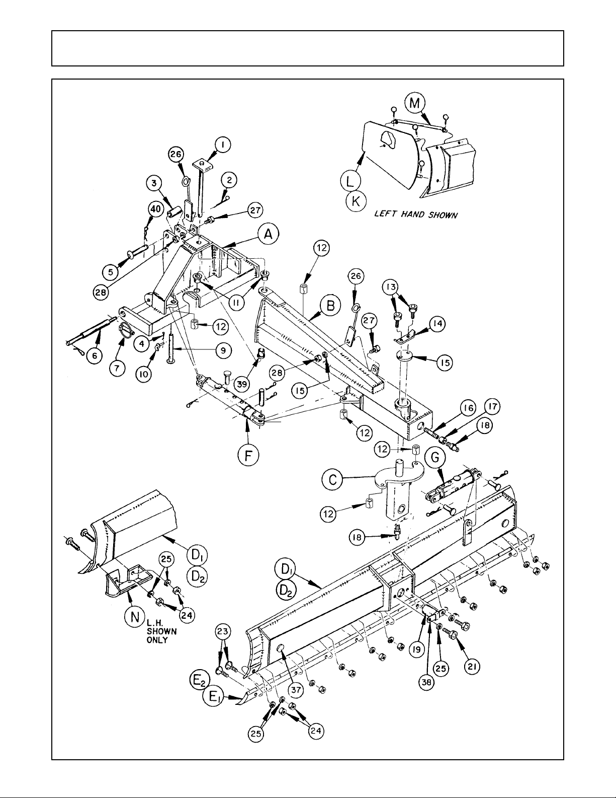
GENERAL ASSEMBLY Rev 03-07
1540 (Oct-01)S/N 14500 -Current Rev 03-07
©2007 Alamo Group Inc. Parts Section – 4
Page 7

GENERAL ASSEMBLY Rev 03-07
ITEM PART NO. QTY. DESCRIPTION
A 00775902 1 A-FRAME
B 00775901 1 MAINFRAME
C 00775900 1 MOLDBOARD CARRIER
D1 69104B1 1 MOLDBOARD (8’)
D2 69137B1 1 MOLDBOARD (10)
E1 441111 1 GRADER BLADE (8’)
E2 691372 1 GRADER BLADE (10’)
F B69115A 2 ADJUSTING LINK
G B69116B 1 ADJUSTING LINK
K 0691360200 1 END PLATE (RIGHT)
L 0691360300 1 END PLATE (LEFT)
M 0691360100 2 BRACE, END PLATE
0691360001 8 LOCKING PIN
N 0691380000 2 SKID SHOE W/HARDWARE (16151 -BELOW)
2A3101120 4 PLOW BOLT (16151-BELOW)
1 69105A 1 PIVOT PIN
2 164024 1 COTTER PIN
3 69113 1 TOP LINK BUSHING
4 2192 1 HAIR PIN COTTER
5 69109 1 TOP LINK PIN
6 69141 2 WRIST PIN
7 2196 4 PIN, LYNCH
9 0831140000 1 SUPPORT STAND
10 69112 1 LOCK PIN
11 6910114 2 BUSHING
12 0692010009 5 BUSHING (FOR USE WITH ALL 1" PIN CYLINDERS AND ADJ. LINKS)
02969064 5 BUSHING (FOR USE WITH ALL 1 1/4" PIN CYLINDERS)
13 02929200 2 BOLT
14 69117 1 RETAINER CLIP
15 69110 1 KING PIN CAP
16 19C1220 1 NIPPLE
17 8639-2 1 COUPLING
18 4720 2 GREASE FITTING
19 69106 1 MOLDBOARD PIVOT PIN WELDMENT
21 02675800 2 BOLT
23 2A3101116 10* PLOW BOLT
24 00010400 10* NUT (16151 -BELOW)
25 00010300 12* LOCKWASHER (16151 -BELOW)
26 0691320000 2 HYDRAULIC HOSE BRACKET ASSY
27 02675800 2 BOLT
28 00695100 2 NUT, TOPLOCK
38 69111 1 RETAINER
39 0831010008 1 BUSHING LOWER MAINFRAME
40 0691360001 1 PIN, KLICK 1/4 X 1-3/4
* Add 2 for 10’ Moldboard
1540 (Oct-01)S/N 14500 -Current Rev 03-07
©2007 Alamo Group Inc. Parts Section – 5
Page 8
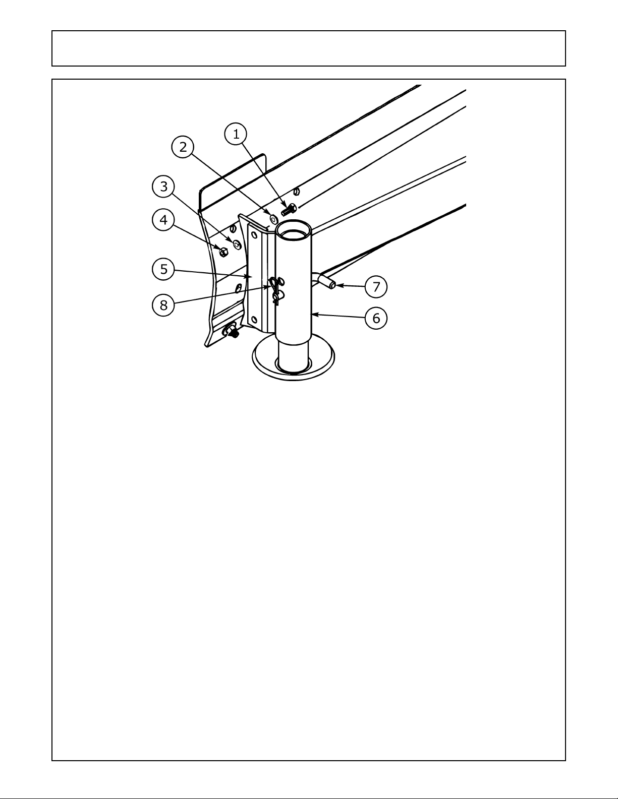
SKID SHOE ASSEMBLY S/N 16152-CURRENT Rev 03-07
ITEM PART NO. QTY. DESCRIPTION
1 02845500 4 HEXB 5/8 NC 2 PL5
2 00001401 4 WASHER
3 00010300 4 LOCKWASHER 5/8
4 00010400 4 NUT 5/8 NC HEX PL
5 00768246 2 WELDMENT, SKID SHOE MOUNT
6 00768243 2 WELDMENT, SKID SHOE
7 00768249 2 PIN, ADJUSTING
8 37107B13 2 CLIP-X HAIR PIN
1540 (Oct-01)S/N 14500 -Current Rev 03-07
©2007 Alamo Group Inc. Parts Section – 6
Page 9
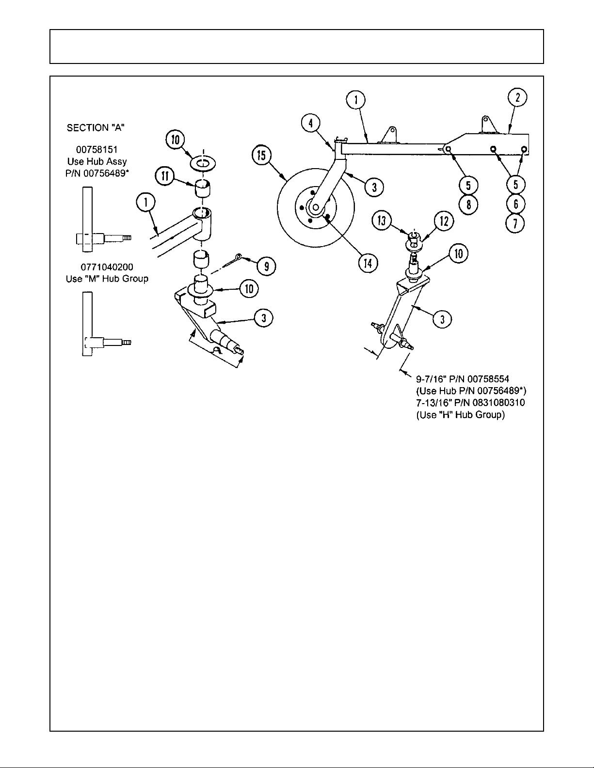
GAUGE WHEEL
ITEM PART NO. QTY. DESCRIPTION
1 0831080200 1 BEAM WELDMENT W/BUSHINGS
2 0691500100 1 TAILWHEEL BRACKET
3 00758151 1 CASTER WLDMT (SINGLE SPINDLE)
00758554 1 CASTER WLDMT (DOUBLE SPINDLE)
4 4720 1 GREASE FITTING
5 7A121080 3 BOLT
6 00003901 2 LOCKWASHER
7 5B12100 2 NUT
8 5GR12100 1 LOCKNUT
9 165024 1 COTTER PIN (SINGLE SPINDLE)
10 301042 2 THRUST WASHER
11 54103A11 2 PIVOT BUSHING
12 59113 1 WASHER
13 5JRA2460 1 NUT (DOUBLE SPINDLE)
14 00756489 1 HUB ASSEMBLY
15 00025200 1 PUNCTURE PROOF TIRE & WHEEL
1540 (Oct-01)S/N 14500 -Current Rev 03-07
©2007 Alamo Group Inc. Parts Section – 7
Page 10
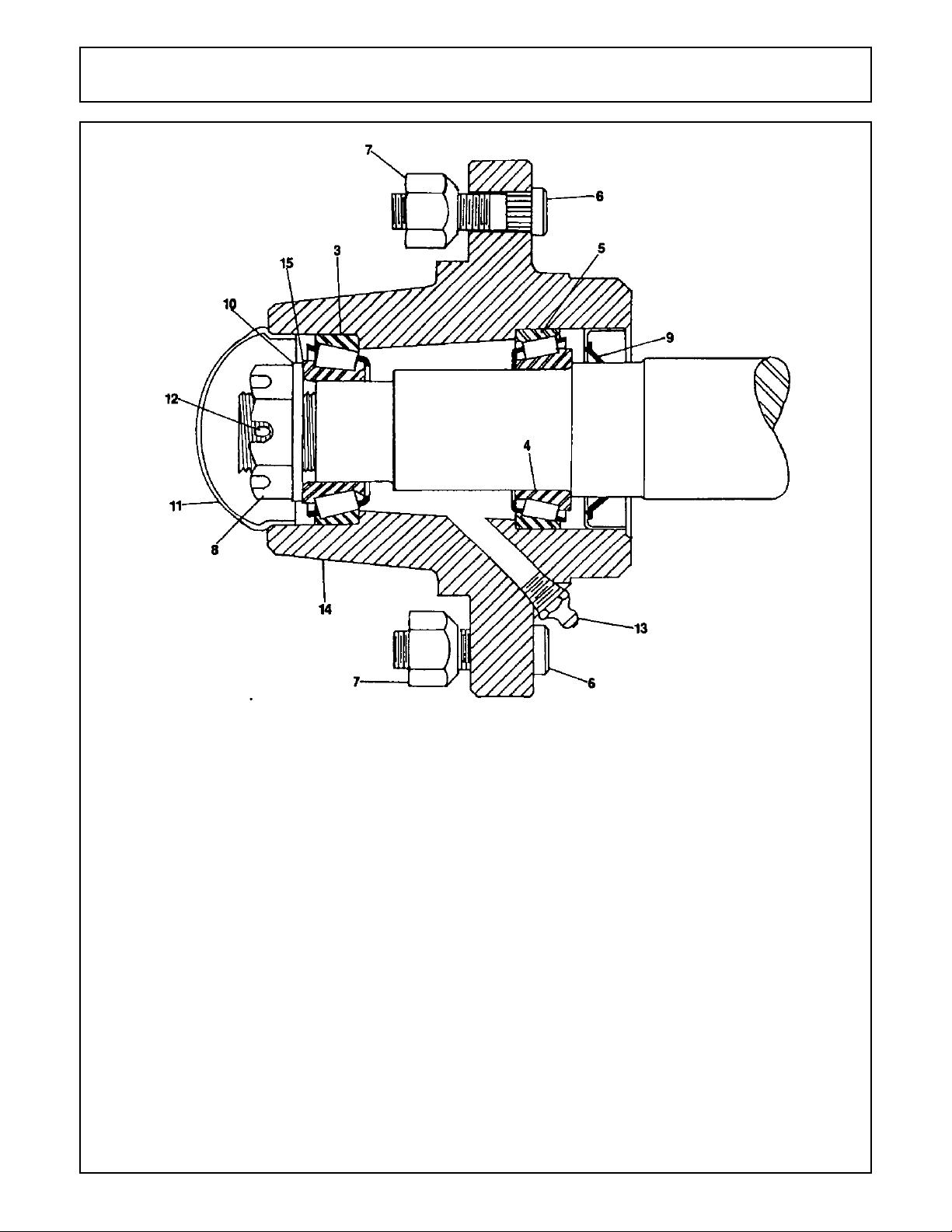
WHEEL HUB ASSEMBLY
ITEM PART NO. QTY. DESCRIPTION
3 00756576 1 BEARING CUP(OUTSIDE)
4 00750434 1 BEARING CONE(INSIDE)
5 00756577 1 BEARING CUP(INSIDE)
6 00756488 5 STUD BOLT
7 00750614 5 NUT
8 00756490 1 BEARING ADJUSTING NUT
9 00756491 1 SEAL
10 00756493 1 WASHER
11 00756492 1 DUST CAP
12 00000400 1 COTTER PIN
13 00003500 1 GREASE FITTING
14 00756000 1 WHEEL HUB
15 0371242102 1 BEARING CONE(OUTSIDE)
16 00756001 ref SPINDLE, SINGLE WHEEL
00756489 ref HUB(W/CUPS & STUDS)
00756528 ref WHEEL HUB ACCESSORY KIT
17 00756002 ref SPINDLE, DUAL WHEEL
1540 (Oct-01)S/N 14500 -Current Rev 03-07
©2007 Alamo Group Inc. Parts Section – 8
Page 11
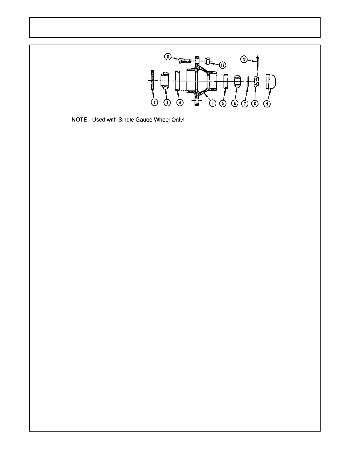
WHEEL HUB
ITEM PART NO. QTY. DESCRIPTION
1 371247SA 1 HUB ASSEMBLY (INCL. 4, 5, 11, 12)
2 371247F 1 GREASE SEAL
3 371247E 1 BEARING CONE (INNER)
4 371247D 1 BEARING CUP (INNER)
5 W-33 1 BEARING CUP (OUTER)
6 371247C 1 BEARING CONE (OUTER)
7 371247H 1 SPINDLE WASHER
8 371247J 1 SPINDLE NUT
9 1621/2010 1 COTTER PIN
10 371247G 1 HUB CAP
11 PT115 5 LUG BOLT
12 PT116 5 LUGNUT
1540 (Oct-01)S/N 14500 -Current Rev 03-07
©2007 Alamo Group Inc. Parts Section – 9
Page 12
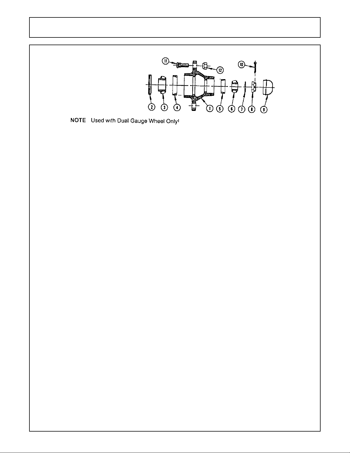
WHEEL HUB
ITEM PART NO. QTY. DESCRIPTION
1 PT110SA 1 HUB ASSEMBLY (INCL. 4, 5, 11, 12)
2 PT106 1 GREASE SEAL
3 PT107 1 BEARING CONE (INNER)
4 W-33 1 BEARING CUP (INNER)
5 PT108 1 BEARING CUP (OUTER)
6 PT109 1 BEARING CONE (OUTER)
7 PT113A 1 SPINDLE WASHER
8 PT114 1 SPINDLE NUT
9 1621/2010 1 COTTER PIN
10 PT112 1 HUB CAP
11 PT115 5 LUG BOLT
12 PT116 5 LUGNUT
1540 (Oct-01)S/N 14500 -Current Rev 03-07
©2007 Alamo Group Inc. Parts Section – 10
Page 13

REAR BLADE HYDRAULICS
ITEM PART NO. QTY 8’ QTY 10’ DESCRIPTION
1 0691600000B 1 2 HYDRAULIC CYLINDER
2 00759715A 1 1 HYDRAULIC CYLINDER
3 691302 2 4 HOSE
4 651132 2 2 HOSE
5 11565 2 4 ELBOW ADAPTER
1540 (Oct-01)S/N 14500 -Current Rev 03-07
©2007 Alamo Group Inc. Parts Section – 11
Page 14

HYDRAULIC CYLINDER Rev 03-05
ITEM PART NO. QTY. DESCRIPTION
0691600000B - HYDRAULIC CYLINDER
1 00775917 1 HEX NUT
2 49045 4 COTTER PIN
3 0116000 1 SETSCREW
4 00775918 4 BUSHING
5 00775916 2 CYLINDER PIN
6 00775915 1 CYLINDER HEAD
7 00778736 1 CYLINDER TUBE
8 00775913 1 CYLINDER ROD
9 00775912 1 ROD CLEVIS
10 00775911 1 PISTON
11 ¤* 1 SEAL HALLITE
12 ¤* 1 SEAL WIPER ROD
13 ¤* 1 SEAL
14 ¤* 1 O-RING
15 ¤* 1 SEAL PSP PISTON RING
16 ¤* 1 WEAR RING
17 00775908 4 HYDRAULIC HOSE
* 02975527 Ref SEAL KIT
1540 (Oct-01)S/N 14500 -Current Rev 03-07
©2007 Alamo Group Inc. Parts Section – 12
Page 15

CYLINDER - HYDRAULIC Rev 03-07
ITEM PART NO. QTY. DESCRIPTION
0691600000 - CYLINDER HYD 16 STX4BOREX2ROD
1 0781070002 1 LOCKNUT PISTON
2 0781070013 2 PIN, CLEVIS
3 0781070014 1 HEAD
4 0781070015 1 PISTON
5 0691600016 1 ROD,PISTON W/CLEVIS
6 0691000100 1 BARREL,HYD.CYLINDER
7 37107B13 2 CLIP-X HAIR PIN
0781070200 - SEAL KIT
1540 (Oct-01)S/N 14500 -Current Rev 03-07
©2007 Alamo Group Inc. Parts Section – 13
Page 16

CYLINDER - HYDRAULIC
ITEM PART NO. QTY. DESCRIPTION
8727 COMPLETE ASSEMBLY
1 8755 1 CAP
2 8757 1 HEAD
3 00760671 1 PISTON
4 8753 1 PISTON ROD
5 8752 1 TUBE
6 8756 4 TIE ROD
7 00023100 1 BOLT
8 00013901 1 HEX NUT
9 8763 1 SEAL KIT
13 8354 2 ref PIVOT PIN
14 00606000 2 ref COTTER PIN
16 8754 1 OUTER CLEVIS
18 02031800 8 TIE ROD NUT
19 4675 1 PISTON NUT
21 7339 1 BREATHER PLUG
651132 2 ref HYDRAULIC HOSE (NOT SHOWN)
94514 2 ref SWIVEL FITTING 90 DEGREES (NOT SHOWN)
1540 (Oct-01)S/N 14500 -Current Rev 03-07
©2007 Alamo Group Inc. Parts Section – 14
Page 17

CYLINDER - HYDRAULIC
ITEM PART NO. QTY. DESCRIPTION
8727A COMPLETE ASSEMBLY
1 00774729 1 CLEVIS CAP
2 00774734 1 ROD CAP
3 00774730 1 PISTON
4 00774753 1 ROD
5 3047111 1 TUBE
6 3047112 4 TIE ROD
15 3047117 1 NYLON THREAD PROTECTOR
16 1917140 1 ROD CLEVIS
17 00774740 1 SET SCREW
18 33003H5C 8 TIE ROD NUT
19 5JRC12160 1 PISTON NUT
20 1917132 1 PORT PLUG
21 2417154 1 BREATHER
00774700 1* SEALANT (NOT SHOWN)
651132 2* HOSE (NOT SHOWN)
94514 2* ELBOW (NOT SHOWN)
0652141311 2* ADAPTER (NOT SHOWN)
8354 2* PIN (NOT SHOWN)
00606000 2* COTTER PIN (NOT SHOWN)
* 00774760 - SEAL KIT FOR 8727A CYL
1540 (Oct-01)S/N 14500 -Current Rev 03-07
©2007 Alamo Group Inc. Parts Section – 15
Page 18

HYDRAULIC CYLINDER
ITEM PART NO. QTY. DESCRIPTION
00759715A - HYDRAULIC CYLINDER
1 2417158 1 CLEVIS CAP
2 2417157 1 ROD CAP
3 00774733 1 PISTON
4 00774736 1 ROD
5 00774747 1 TUBE
6 00774741 4 TIE ROD
7 ¤* 2 END CAP O-RING
8 ¤* 1 ROD, WIPER SEAL
9 ¤* 1 ROD, DUST SEAL
10 ¤* 1 PISTON SEAL
11 ¤* 2 PISTON WEAR RING
12 ¤* 2 END CAP BACKUP WASHERS
13 3047117 1 NYLON THREAD PROTECTOR
14 1917140 1 ROD CLEVIS
15 00774740 1 SET SCREW
16 33005H5C 8 TIE ROD NUT
17 5JRC16140 1 PISTON NUT
18 1917132 1 PORT PLUG
19 11565 2 ELBOW, FITTING 90DEGREES
20 651132 2 HYDRAULIC HOSE
* 02975527 - SEAL KIT
1540 (Oct-01)S/N 14500 -Current Rev 03-07
©2007 Alamo Group Inc. Parts Section – 16
Page 19

CYLINDER - HYDRAULIC
ITEM PART NO. QTY. DESCRIPTION
1 00759715 1 HYDRAULIC CYLINDER W/CLEVIS PIN
2 691302 1 HYDRAULIC HOSE
3 94514 1 STREET ELBOW
4 4376 8 NUT
5 7343 2 COTTER PIN
6 4378 1 NUT
7 4427 1 BOLT
8 4675 1 PISTON NUT
9 8354 2 CLEVIS PIN
10 8784 1 CAP
11 00759734 1 TUBE
12 00759733 1 PISTON
13 00759735 1 PISTON ROD
14 8786 1 HEAD
15 8754 1 FEMALE CLEVIS
16 00759736 4 TIE ROD
00759737 1 SEAL KIT
1540 (Oct-01)S/N 14500 -Current Rev 03-07
©2007 Alamo Group Inc. Parts Section – 17
Page 20

CYLINDER - HYDRAULIC
ITEM PART NO. QTY. DESCRIPTION
1 B69135A 1 COMPLETE CYLINDER W/CLEVIS PIN
2 651132 2 HYDRAULIC HOSE
3 00001200 8 HEX NUT
4 00000400 2 COTTER PIN
5 5B6160 1 HEX NUT
6 7E62414 1 BOLT
7 691351 1 PISTON NUT
8 8354 1 CLEVIS PIN
9 69135A2 1 CLEVIS BASE
10 6913010 1 TUBE
11 6913011 1 PISTON
12 6913012 1 ROD
691353 1 ROD
13 6913013 1 HEAD
69130A13 1 HEAD
14 691354 1 CLEVIS, PISTON ROD
15 6913014 4 TIE ROD
69130A14 4 TIE ROD
16 00749508 1 PIPE PLUG
17 691356 1 CLEVIS BASE PIN
1540 (Oct-01)S/N 14500 -Current Rev 03-07
©2007 Alamo Group Inc. Parts Section – 18
Page 21

CYLINDER - HYDRAULIC
ITEM PART NO. QTY. DESCRIPTION
1 B69135A 1 COMPLETE CYLINDER W/CLEVIS PIN
2 651132 2 HYDRAULIC HOSE
3 00001200 8 HEX NUT
4 00000400 2 COTTER PIN
5 5B6240 1 HEX NUT
6 7E62414 1 BOLT
7 691351 1 PISTON NUT
8 8354 1 CLEVIS PIN
9 0691350014 1 CLEVIS BASE
10 0691350006 1 TUBE
11 0691350004 1 PISTON
12 0691350005 1 ROD
13 0691350010 1 HEAD
14 0651130022 1 CLEVIS, PISTON ROD
15 0691350011 4 TIE ROD
1540 (Oct-01)S/N 14500 -Current Rev 03-07
©2007 Alamo Group Inc. Parts Section – 19
Page 22

CYLINDER - HYDRAULIC
ITEM PART NO. QTY. DESCRIPTION
1 B69131B1 1 HYDRAULIC CYLINDER COMPLETE
2 651132 1 HYDRAULIC HOSE
3 00001200 8 NUT
4 00000400 2 COTTER PIN
5 5B6160 1 HEX NUT
6 6511322 1 BOLT
7 6511320 1 PISTON NUT
8 8354 2 CLEVIS PIN
9 65113A12 1 BASE CLEVIS
10 691314 1 TUBE
11 691315 1 PISTON
12 69131B10 1 PISTON ROD
691316 1 PISTON ROD
13 65113B8 1 HEAD
65130A4 1 HEAD
14 691354 1 PISTON ROD CLEVIS
65130A12 1 PISTON ROD CLEVIS
15 691317 4 TIE ROD
16 00749508 1 PIPE PLUG
65113A30 ref SEAL KIT (NOT SHOWN)
691318 ref SEAL KIT (NOT SHOWN)
1540 (Oct-01)S/N 14500 -Current Rev 03-07
©2007 Alamo Group Inc. Parts Section – 20
Page 23

CYLINDER - HYDRAULIC
ITEM PART NO. QTY. DESCRIPTION
1 B69131B1 1 HYDRAULIC CYLINDER COMPLETE
2 651132 1 HYDRAULIC HOSE
3 00001200 8 NUT
4 00000400 2 COTTER PIN
5 5B6240 1 HEX NUT
6 7E62414 1 BOLT
7 691351 1 PISTON NUT
8 8354 2 CLEVIS PIN
9 0651130001 1 BASE CLEVIS
10 0691310002 1 TUBE
11 0651130005 1 PISTON
12 0691310001 1 PISTON ROD
13 0651130016 1 HEAD
14 0651130022 1 PISTON ROD CLEVIS
15 691317 4 TIE ROD
0651130014 ref SEAL KIT (NOT SHOWN)
1540 (Oct-01)S/N 14500 -Current Rev 03-07
©2007 Alamo Group Inc. Parts Section – 21
Page 24

HOSE CONNECTIONS - HYDRAULIC
ITEM PART NO. QTY. DESCRIPTION
1 94514 1 SWIVEL FITTING
2 B65131 1 QUICK COUPLER ASSEMBLY
3 02963649 1 NIPPLE
4 651311 1 COUPLER
5 651312 1 COUPLER TIP - MALE
1540 (Oct-01)S/N 14500 -Current Rev 03-07
©2007 Alamo Group Inc. Parts Section – 22
Page 25

BRACKET ASSY - CONTROL VALVE
ITEM PART NO. QTY. DESCRIPTION
1 B651401 1 BRACKET W/FASTENERS
2 00016200 6 BOLT
3 13500 6 LOCKWASHER
4 5B5180 6 HEX NUT
1540 (Oct-01)S/N 14500 -Current Rev 03-07
©2007 Alamo Group Inc. Parts Section – 23
Page 26

CONTROL VALVE ASSEMBLY
1540 (Oct-01)S/N 14500 -Current Rev 03-07
©2007 Alamo Group Inc. Parts Section – 24
Page 27

CONTROL VALVE ASSEMBLY
ITEM PART NO. QTY. DESCRIPTION
0691700000 1 CONTROL VALVE (OPEN CTR)
0691710000 1 CONTROL VALVE (CLOSED CTR)
1 6514042 1 CLOSED CTR PLUG ASSY(INCL. 2,3, &4)
2 6514041 1 O-RING SEAL
3 6514044 1 BACK-UP WASHER
4 6514045 1 O-RING SEAL
5 6514039 1 CONV. PLUG ASSY.(FOR OPEN CTR)
6 6514041 1 O-RING SEAL
7 0691700001 1 ADJ. RELIEF ASSEMBLY(INCL. 10-13)
8 6514034 1 O-RING SEAL
9 6514035 1 BACK-UP WASHER
10 6514036 1 O-RING SEAL
11 6514037 1 NO-RELIEF ASSEMBLY(INCL. 12-14)
12 6514034 1 O-RING SEAL
13 6514035 1 BACK-UP WASHER
14 6514036 1 O-RING SEAL
16 6514029 3 PLUG ONLY
17 6514028 3 O-RING SEAL
18 6514027 3 SPRING
19 6514026 3 LOAD CHECK POPPET
20 65140A49 3 HANDLE & BRACKET ASSY(INCL 21-23)
21 65140A47 3 HANDLE
22 65140A46 3 HANDLE BRACKET
23 65140A48 3 PIN KIT
24 7E4204 3 BOLT
25 6514012 6 RETAINER PLATE
26 6514013 6 SPOOL SEAL
27 6514018 3 STOP WASHER
28 6514019 3 SPRING
29 6514020 3 STOP COLLAR
30 6514021 3 WASHER
31 6514022 3 END CAP
32 00021400 12 BOLT
33 6514014 3 SPACER
1540 (Oct-01)S/N 14500 -Current Rev 03-07
©2007 Alamo Group Inc. Parts Section – 25
Page 28

VALVE SELECTOR
ITEM PART NO. QTY. DESCRIPTION
1 0781300000 1 VALVE ASSEMBLY (COMPLETE)
2 0781300005 2 SEAL
1540 (Oct-01)S/N 14500 -Current Rev 03-07
©2007 Alamo Group Inc. Parts Section – 26
Page 29

ADJUST LINK ASSEMBLY
ITEM PART NO. QTY. DESCRIPTION
B69116B - ADJUST LINK ASSEMBLY
1 00776119 1 WDMT. ADJUSTING LINK HOUSING
2 00776121 1 WDMT. ADJUSTING LINK ROD
3 00775916 2 PIN, CYLINDER
4 691154 1 PIN, CLEVIS
5 00606000 4 PIN, COTTER
6 37107B13 1 CLIP, HAIR PIN
7 02969064 2 BUSHING SPRING (NOT SHOWN)
1540 (Oct-01)S/N 14500 -Current Rev 03-07
©2007 Alamo Group Inc. Parts Section – 27
Page 30

ADJUST LINK ASSEMBLY
ITEM PART NO. QTY. DESCRIPTION
B69116B¤ - ADJUST LINK ASSEMBLY
1 69116B1 1 ADJUSTING LINK HOUSING
2 69116A2 1 ADJUSTING LINK ROD
3 691154 3 PIN
4 37107B13 3 CLIP PIN
1540 (Oct-01)S/N 14500 -Current Rev 03-07
©2007 Alamo Group Inc. Parts Section – 28
Page 31

ADJUSTING LINK - MANUAL
ITEM PART NO. QTY. DESCRIPTION
- B69115A - MAINFRAME SWING & MOLDBOARD PIVOT
A 69115A1 1 ADJUSTING LINK HOUSING WELDMENT
B 69115A2 1 ADJUSTING LINK ROD WELDMENT
C 691154 3 CLEVIS PIN
D 00000400 3 COTTER PIN
1540 (Oct-01)S/N 14500 -Current Rev 03-07
©2007 Alamo Group Inc. Parts Section – 29
Page 32

ADJUSTING LINK - MANUAL
ITEM PART NO. QTY. DESCRIPTION
B69116B - MOLDBOARD TILT
A 69116B1 1 ADJUSTING LINK HOUSING WELDMENT
B 69116A2 1 ADJUSTING LINK ROD WELDMENT
C 691154 3 CLEVIS PIN
D 00000400 3 COTTER PIN
1540 (Oct-01)S/N 14500 -Current Rev 03-07
©2007 Alamo Group Inc. Parts Section – 30
Page 33

SAFETY DECAL SHEETS
ITEM PART NO. QTY. DESCRIPTION
1 00776261 1 SHEET,1540 BLADE DECAL
2 00776481 1 SHEET,MANUALCANISTER DECAL
3 1458392 1 DECAL,RED REFLECTOR (NOT SHOWN)
4 1458393 1 DECAL,YELLOW REFLECTOR (NOT SHOWN)
1540 (Oct-01)S/N 14500 -Current Rev 03-07
©2007 Alamo Group Inc. Parts Section – 31
Page 34

Page 35

SERVIS-RHINO
LIMITED WARRANTY
1. LIMITED WARRANTIES
1.01.Servis-Rhino warrants for one year from the purchase date to the original non-commercial, governmental, or municipal
purchaser (“Purchaser”) and warrants for six months to the original commercial or industrial purchaser (“Purchaser”)
that the goods purchased are free from defects in material or workmanship.
1.02.Manufacturer will replace for the Purchaser any part or parts found, upon examination at one of its factories, to be
defective under normal use and service due to defects in material or workmanship.
1.03.This limited warranty does not apply to any part of the goods which has been subjected to improper or abnormal use,
negligence, alteration, modification, or accident, damaged due to lack of maintenance or use of wrong fuel, oil, or
lubricants, or which has served its normal life. This limited warranty does not apply to any part of any internal
combustion engine, or expendable items such as blades, shields, guards, or pneumatic tires except as specifically found
in your Operator’s Manual.
1.04.Except as provided herein, no employee, agent, Dealer, or other person is authorized to give any warranties of any
nature on behalf of Manufacturer.
2. REMEDIES AND PROCEDURES.
2.01.This limited warranty is not effective unless the Purchaser returns the Registration and Warranty Form to Manufacturer
within 30 days of purchase.
2.02.Purchaser claims must be made in writing to the Authorized Dealer (“Dealer”) from whom Purchaser purchased the
goods or an approved Authorized Dealer (“Dealer”) within 30 days after Purchaser learns of the facts on which the
claim is based.
2.03.Purchaser is responsible for returning the goods in question to the Dealer.
2.04.If after examining the goods and/or parts in question, Manufacturer finds them to be defective under normal use and
service due to defects in material or workmanship, Manufacturer will:
(a) Repair or replace the defective goods or part(s) or
(b) Reimburse Purchaser for the cost of the part(s) and reasonable labor charges (as determined by Manufacturer)
if Purchaser paid for the repair and/or replacement prior to the final determination of applicability of the warranty
by Manufacturer.
The choice of remedy shall belong to Manufacturer.
2.05.Purchaser is responsible for any labor charges exceeding a reasonable amount as determined by Manufacturer and
for returning the goods to the Dealer, whether or not the claim is approved. Purchaser is responsible for the transportation cost for the goods or part(s) from the Dealer to the designated factory.
3. LIMITATION OF LIABILITY.
3.01.MANUFACTURER DISCLAIMS ANY EXPRESS (EXCEPT AS SET FORTH HEREIN) AND IMPLIED WARRANTIES
WITH RESPECT TO THE GOODS INCLUDING, BUT NOT LIMITED TO, MERCHANTABILITY AND FITNESS
FOR A PARTICULAR PURPOSE.
3.02.MANUFACTURER MAKES NO WARRANTY AS TO THE DESIGN, CAPABILITY, CAPACITY, OR SUITABILITY FOR
USE OF THE GOODS.
3.03.EXCEPT AS PROVIDED HEREIN, MANUFACTURER SHALL HAVE NO LIABILITY OR RESPONSIBILITY TO
PURCHASER OR ANY OTHER PERSON OR ENTITY WITH RESPECT TO ANY LIABILITY, LOSS, OR DAMAGE
CAUSED OR ALLEGED TO BE CAUSED DIRECTLY OR INDIRECTLY BY THE GOODS INCLUDING, BUT NOT
LIMITED TO, ANY INDIRECT, SPECIAL, CONSEQUENTIAL, OR INCIDENTAL DAMAGES RESULTING FROM
THE USE OR OPERATION OF THE GOODS OR ANY BREACH OF THIS WARRANTY. NOT WITHSTANDING THE
ABOVE LIMITATIONS AND WARRANTIES, MANUFACTURER’S LIABILITY HEREUNDER FOR DAMAGES
INCURRED BY PURCHASER OR OTHERS SHALL NOT EXCEED THE PRICE OF THE GOODS.
3.04.NO ACTION ARISING OUT OF ANY CLAIMED BREACH OF THIS WARRANTY OR TRANSACTIONS UNDER
THIS WARRANTY MAY BE BROUGHT MORE THAN TWO (2) YEARS AFTER THE CAUSE OF ACTION HAS
OCCURRED.
4. MISCELLANEOUS.
4.01.Proper Venue for any lawsuits arising from or related to this limited warranty shall be only in Guadalupe County,
Texas.
4.02.Manufacturer may waive compliance with any of the terms of this limited warranty, but no waiver of any terms shall
be deemed to be a waiver of any other term.
4.03.If any provision of this limited warranty shall violate any applicable law and is held to be unenforceable, then the
invalidity of such provision shall not invalidate any other provisions herein.
4.04.Applicable law may provide rights and benefits to purchaser in addition to those provided herein.
KEEP FOR YOUR RECORDS
ATTENTION: Purchaser should fill in the blanks below for his reference when buying repair parts and/or for proper machine
identification when applying for warranty.
Servis-Rhino Implement Model _______________________________ Serial Number________________________________
Date Purchased __________________________________________ Dealer ______________________________________
ATTENTION:
READ YOUR OPERATOR'S MANUAL
RHINO
1020 S. Sangamon A ve.
®
Gibson City, IL 60936
800-446-5158
Email: parts@servis-rhino.com
R
Page 36

TO THE OWNER/OPERATOR/DEALER
To keep your implement running efficiently and safely, read your manual thoroughly and follow these directions and
the Safety Messages in this Manual. The Table of Contents clearly identifies each section where you can easily
find the information you need.
The OCCUPATIONAL SAFETY AND HEALTH ACT (1928.51 Subpart C) makes these minimum safety
requirements of tractor operators:
REQUIRED OF THE OWNER:
1. Provide a Roll-Over-Protective Structure that meets the requirements of this Standard; and
2. Provide Seatbelts that meet the requirements of this paragraph of this Standard and SAE J4C; and
3. Ensure that each employee uses such Seatbelt while the tractor is moving; and
4. Ensure that each employee tightens the Seatbelt sufficiently to confine the employee to the protected
area provided by the ROPS.
REQUIRED OF THE OPERATOR
1. Securely fasten seatbelt if the tractor has a ROPS.
2. Where possible, avoid operating the tractor near ditches, embankments, and holes.
3. Reduce speed when turning, crossing slopes, and on rough, slick, or muddy surfaces.
4. Stay off slopes too steep for safe operation.
5. Watch where you are going - especially at row ends, on roads, and around trees.
6. Do not permit others to ride.
7. Operate the tractor smoothly - no jerky turns, starts, or stops.
8. Hitch only to the drawbar and hitch points recommended by the tractor manufacturer.
9. When the tractor is stopped, set brakes securely and use park lock, if available.
Keep children away from danger all day, every day...
Equip tractors with rollover protection (ROPS) and keep all machinery
guards in place...
Please work, drive, play and live each day with care and concern for
your safety and that of your family and fellow citizens.
Page 37

Printed U.S.A.
P/N 69 7P1540 Rear Blades PL 06/01
 Loading...