

Page 1
INSTALLATION INSTRUCTIONS
ISO 9001:2008
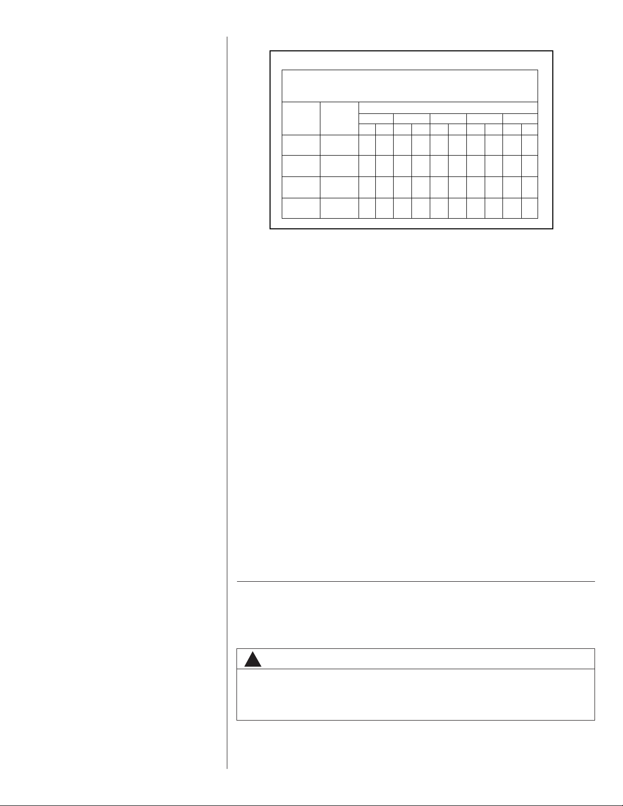
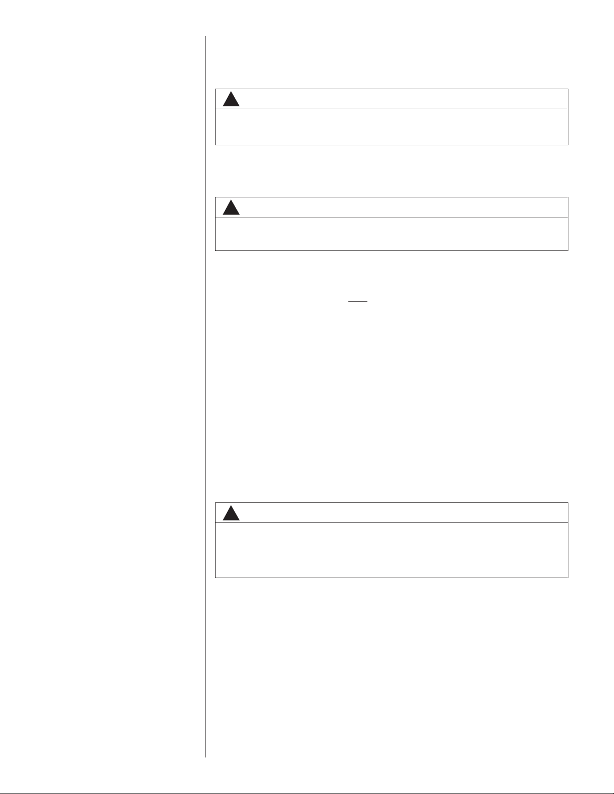
Seasonal Energy Efficiency Ratio (SEER)
Annual Fuel Utilization Efficiency -
AFUE
HIGHMID
13.0 14.0 16.0
80.0%
RRNL RRPL RRRL
THIS MODEL
10.6
—
Uses least energy
➞
16.05
78% 82% 88% 97%
PACKAGE GAS ELECTRIC
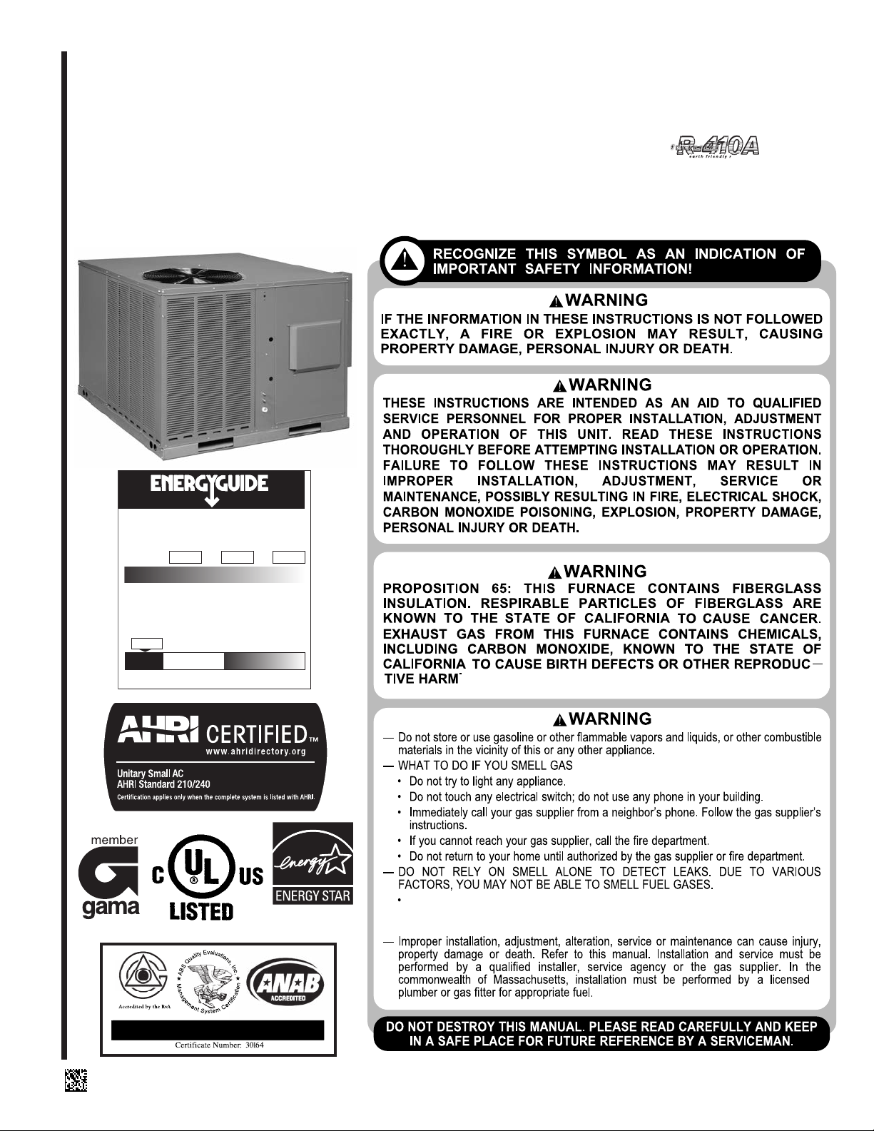
FEATURING EARTH-FRIENDLY R-410A REFRIGERANT
RRNL-B/C 13 SEER (2-5 TONS)
RRPL-B 14 SEER (2-5 TONS)
RRRL-C UP TO 16 SEER (2-5 TONS)
(14 SEER &
ABOVE)
U.L. recognized fuel gas and CO (carbon monoxide) detectors are recommended in all
applications, and their installation should be in accordance with the manufacturer’s
recommendations and/or local laws, rules, regulations, or customs.
SUPERSEDES 92-21916-30-08
92-21916-30-09
Page 2

TABLE OF CONTENTS
I. Safety Information .................................................................................................3
II. Introduction............................................................................................................6
III. Checking Product Received..................................................................................6
IV. Specifications ........................................................................................................6
A. General .............................................................................................................6
B. Major Components............................................................................................6
C.R-410A Refrigerant...........................................................................................6
D.Comfort Alert System........................................................................................7
1. Comfort Alert.................................................................................................7
2. High Pressure Control...................................................................................8
3. Low Pressure Control....................................................................................8
4. Comfort Alert With Active Protection.............................................................8
V. Unit Dimensions ..................................................................................................11
VI. Installation ...........................................................................................................13
A. General ...........................................................................................................13
1. Pre-Installation Check................................................................................13
2. Location Considerations.............................................................................13
B. Outside Installation..........................................................................................13
C.Attaching Exhaust and Combustion Air Inlet Hoods .......................................14
D.Cover Panel Installation/Conversion Procedure .............................................15
1. Horizontal to Downflow ...............................................................................15
2. Downflow to Horizontal ...............................................................................15
E. Clearances......................................................................................................15
F. Rooftop Installation .........................................................................................17
G.Ductwork .........................................................................................................17
H.Return Air........................................................................................................19
I. Filters...............................................................................................................20
VII. Gas Supply, Condensate Drain and Piping.........................................................22
A. Gas Connection ..............................................................................................22
B. LP Conversion Single Stage Gas Heat...........................................................23
C.LP Conversion Two Stage Gas Heat..............................................................24
D.NOx Models ....................................................................................................24
E. Adjusting or Checking Furnace Input..............................................................24
F. Condensate Drain...........................................................................................25
VIII. Wiring ..................................................................................................................25
A. Power Supply..................................................................................................25
B. Hook Up ..........................................................................................................27
C.Internal Wiring.................................................................................................27
D.Thermostat......................................................................................................27
IX. Furnace Section Controls and Ignition System ...................................................28
A. Normal Furnace Operating Sequence Single Stage Gas Heat.......................28
B. Normal Furnace Operating Sequence Two Stage Gas Heat..........................28
C.Operating Instructions.....................................................................................30
D.Burners............................................................................................................31
E. Manual Reset Overtemperature Control .........................................................31
D.Pressure Switch..............................................................................................31
G.Limit Control....................................................................................................31
X. System Operating Information.............................................................................31
A. Advise the Customer.......................................................................................31
B. Furnace Section Maintenance ........................................................................31
C.Lubrication.......................................................................................................32
D.Cooling Section Maintenance .........................................................................32
E. Replacement Parts..........................................................................................33
F. Charging..........................................................................................................33
G.Blower Motor Speed Adjustments...................................................................33
XI. Units with ECM Blower Motors (RRRL-B Models Only)......................................36
A. ECM Motor Interface Control and Settings (RRRL Units Only).......................36
B. Transformer Protection ...................................................................................37
C.Using the Onboard LED to Determine Blower CFM........................................37
D.Unit Operation with Two-Stage Cooling..........................................................38
E. Cooling Airflow Adjustments ...........................................................................38
F. Heating Airflow Adjustments...........................................................................41
G.Cooling Delay Profiles.....................................................................................41
H.Cooling Mode Dehumidification ......................................................................42
I. On Demand Dehumidification Airflow Adjustment ..........................................42
XII. General Data..................................................................................................44-66
XIII. Miscellaneous.................................................................................................67-71
XIV. Airflow Performance Data ..............................................................................72-76
XV. Wiring Diagrams.............................................................................................77-87
XVI. Charge Charts..............................................................................................88-103
XVII. Troubleshooting..........................................................................................104-105
XVIII. Comfort Alert Diagnostic Chart...................................................................106-107
2
Page 3
I. SAFETY INFORMATION
WARNING
!
PROPOSITION 65: THIS FURNACE CONTAINS FIBERGLASS INSULATION.
RESPIRABLE PARTICLES OF FIBERGLASS ARE KNOWN TO THE STATE OF
CALIFORNIA TO CAUSE CANCER. EXHAUST GAS FROM THIS FURNACE
CONTAINS CHEMICALS, INCLUDING CARBON MONOXIDE, KNOWN TO THE
STATE OF CALIFORNIA TO CAUSE BIRTH DEFECTS OR OTHER REPRODUCTIVE HARM.
WARNING
!
THE MANUFACTURER’S WARRANTY DOES NOT COVER ANY DAMAGE OR
DEFECT TO THE AIR CONDITIONER CAUSED BY THE ATTACHMENT OR USE
OF ANY COMPONENTS, ACCESSORIES OR DEVICES (OTHER THAN THOSE
AUTHORIZED BY THE MANUFACTURER) INTO, ONTO OR IN CONJUNCTION
WITH THE AIR CONDITIONER. YOU SHOULD BE AWARE THAT THE USE OF
UNAUTHORIZED COMPONENTS, ACCESSORIES OR DEVICES MAY
ADVERSELY AFFECT THE OPERATION OF THE AIR CONDITIONER AND MAY
ALSO ENDANGER LIFE AND PROPERTY. THE MANUFACTURER DISCLAIMS
ANY RESPONSIBILITY FOR SUCH LOSS OR INJURY RESULTING FROM THE
USE OF SUCH UNAUTHORIZED COMPONENTS, ACCESSORIES OR DEVICES.
WARNING
!
UNITS ARE NOT DESIGN CERTIFIED TO BE INSTALLED INSIDE THE STRUCTURE. DOING SO CAN CAUSE INADEQUATE UNIT PERFORMANCE AS WELL
AS PROPERTY DAMAGE AND CARBON MONOXIDE POISONING RESULTING
IN PERSONAL INJURY OR DEATH.
WARNING
!
DISCONNECT ALL POWER TO UNIT BEFORE STARTING MAINTENANCE.
FAILURE TO DO SO CAN CAUSE ELECTRICAL SHOCK RESULTING IN PERSONAL INJURY OR DEATH.
WARNING
!
THESE UNITS ARE DESIGNED CERTIFIED FOR OUTDOOR INSTALLATION
ONLY. INSTALLATION INSIDE ANY PART OF A STRUCTURE CAN RESULT IN
INADEQUATE UNIT PERFORMANCE AS WELL AS PROPERTY DAMAGE.
INSTALLATION INSIDE CAN ALSO CAUSE RECIRCULATION OF FLUE PRODUCTS INTO THE CONDITIONED SPACE RESULTING IN PERSONAL INJURY
OR DEATH.
WARNING
!
THIS UNIT MUST NOT BE INSTALLED DIRECTLY ON WOOD FLOORING, CLASS
A, CLASS B OR CLASS C ROOF COVERING MATERIALS, OR ANY OTHER COMBUSTIBLE STRUCTURE EXCEPT AS SPECIFIED IN FIGURE 16. FAILURE TO
ADHERE TO THIS WARNING CAN CAUSE A FIRE OR EXPLOSION RESULTING
IN PROPERTY DAMAGE, PERSONAL INJURY OR DEATH.
WARNING
!
DO NOT, UNDER ANY CIRCUMSTANCES, CONNECT RETURN DUCTWORK TO
ANY OTHER HEAT PRODUCING DEVICE SUCH AS FIREPLACE INSERT,
STOVE, ETC. UNAUTHORIZED USE OF SUCH DEVICES MAY RESULT IN FIRE,
CARBON MONOXIDE POISONING, EXPLOSION, PERSONAL INJURY, OR
PROPERTY DAMAGE.
3
Page 4
WARNING
!
NEVER ALLOW PRODUCTS OF COMBUSTION OR THE FLUE PRODUCTS TO
ENTER THE RETURN AIR DUCTWORK, OR THE CIRCULATING AIR SUPPLY.
ALL RETURN DUCTWORK MUST BE ADEQUATELY SEALED AND SECURED
TO THE FURNACE WITH SHEET METAL SCREWS, AND JOINTS TAPED. ALL
OTHER DUCT JOINTS MUST BE SECURED WITH APPROVED CONNECTIONS
AND SEALED AIRTIGHT.
FAILURE TO PREVENT PRODUCTS OF COMBUSTION FROM BEING CIRCULATED INTO THE LIVING SPACE CAN CREATE POTENTIALLY HAZARDOUS
CONDITIONS, INCLUDING CAROBON MONOXIDE POISONING THAT COULD
RESULT IN PERSONAL INJURY OR DEATH.
WARNING
!
DO NOT USE AN OPEN FLAME TO CHECK FOR LEAKS. THE USE OF AN OPEN
FLAME CAN RESULT IN FIRE, EXPLOSION, PROPERTY DAMAGE, PERSONAL
INJURY OR DEATH.
WARNING
!
THIS UNIT IS EQUIPPED AT THE FACTORY FOR USE ON NATURAL GAS ONLY.
CONVERSION TO LP GAS REQUIRES A SPECIAL KIT SUPPLIED BY THE DISTRIBUTOR OR MANUFACTURER. MAILING ADDRESSES ARE LISTED ON THE
FURNACE RATING PLATE, PARTS LIST AND WARRANTY. FAILURE TO USE
THE PROPER CONVERSION KIT CAN CAUSE FIRE, CARBON MONOXIDE POISONING, EXPLOSION, PERSONAL INJURY, PROPERTY DAMAGE OR DEATH.
WARNING
!
TURN OFF THE MAIN ELECTRICAL POWER AT THE BRANCH CIRCUIT DISCONNECT CLOSEST TO THE UNIT BEFORE ATTEMPTING ANY WIRING. FAILURE
TO DO SO CAN CAUSE ELECTRICAL SHOCK RESULTING IN PERSONAL
INJURY OR DEATH.
WARNING
!
DO NOT ATTEMPT TO MANUALLY LIGHT THIS FURNACE WITH A MATCH OR
ANY OPEN FLAME. ATTEMPTING TO DO SO CAN CAUSE AN EXPLOSION OR
FIRE RESULTING IN PROPERTY DAMAGE, PERSONAL INJURY OR DEATH.
WARNING
!
IF YOU DO NOT FOLLOW THESE INSTRUCTIONS EXACTLY, A FIRE OR
EXPLOSION MAY RESULT CAUSING PROPERTY DAMAGE, PERSONAL
INJURY OR LOSS OF LIFE.
WARNING
!
THE SPARK IGNITOR AND IGNITION LEAD FROM THE IGNITION CONTROL
ARE HIGH VOLTAGE. KEEP HANDS OR TOOLS AWAY TO PREVENT ELECTRICAL SHOCK. SHUT OFF ELECTRICAL POWER BEFORE SERVICING ANY
OF THE CONTROLS. FAILURE TO ADHERE TO THIS WARNING CAN RESULT
IN PERSONAL INJURY OR DEATH.
WARNING
!
SHOULD OVERHEATING OCCUR OR THE GAS SUPPLY FAIL TO SHUT OFF,
SHUT OFF THE MANUAL GAS VALVE TO THE APPLIANCE BEFORE SHUTTING OFF THE ELECTRICAL SUPPLY. FAILURE TO DO SO CAN RESULT IN
AN EXPLOSION OR FIRE CAUSING PROPERTY DAMAGE, SEVERE PERSONAL INJURY OR DEATH!
4
Page 5
WARNING
!
DO NOT JUMPER THIS DEVICE! DO NOT reset the overtemperature control
without taking corrective action to assure that an adequate supply of combustion air is maintained under all conditions of operation. Failure to do so can
result in carbon monoxide poisoning or death. Replace this control only with
the identical replacement part.
WARNING
!
LABEL ALL WIRES PRIOR TO DISCONNECTION WHEN SERVICING CONTROLS. WIRING ERRORS CAN CAUSE IMPROPER AND DANGEROUS OPERATION RESULTING IN FIRE, ELECTRICAL SHOCK, PROPERTY DAMAGE, PERSONAL INJURY OR DEATH.
WARNING
!
HOLES IN THE EXHAUST TRANSITION OR HEAT EXCHANGER CAN CAUSE
TOXIC FUMES TO ENTER THE HOME. THE EXHAUST TRANSITION OR HEAT
EXCHANGER MUST BE REPLACED IF THEY HAVE HOLES OR CRACKS IN
THEM. FAILURE TO DO SO CAN CAUSE CARBON MONOXIDE POISONING
RESULTING IN PERSONAL NJURY OR DEATH.
WARNING
!
DISCONNECT MAIN ELECTRICAL POWER TO THE UNIT BEFORE ATTEMPTING MAINTENANCE. FAILURE TO DO SO MAY RESULT IN ELECTRICAL
SHOCK OR SEVERE PERSONAL INJURY OR DEATH.
WARNING
!
LABEL ALL WIRES PRIOR TO DISCONNECTION WHEN SERVICING THE UNIT.
WIRING ERRORS CAN CAUSE IMPROPER AND DANGEROUS OPERATION
RESULTING IN FIRE, ELECTRICAL SHOCK, PROPERTY DAMAGE, SEVERE
PERSONAL INJURY OR DEATH.
WARNING
!
DISCONNECT MAIN ELECTRICAL POWER TO THE UNIT BEFORE ATTEMPTING TO CHANGE BLOWER SPEEDS. FAILURE TO DO SO MAY RESULT IN
ELECTRICAL SHOCK OR SEVERE PERSONAL INJURY OR DEATH.
WARNING
!
DISCONNECT ALL POWER TO UNIT BEFORE SERVICING. CONTACTOR MAY
BREAK ONLY ONE SIDE. FAILURE TO SHUT OFF POWER CAN CAUSE ELECTRICAL SHOCK RESULTING IN PERSONAL INJURY OR DEATH.
!
CAUTION
R-410A systems operate at higher pressures than R-22 systems. Do not use
R-22 service equipment or components on R-410A equipment.
5
Page 6
WARNING
!
IMPORTANT: ALL MANUFACTURER PRODUCTS MEET CURRENT
FEDERAL OSHA GUIDELINES FOR
SAFETY. CALIFORNIA
PROPOSITION 65 WARNINGS ARE
REQUIRED FOR CERTAIN PRODUCTS, WHICH ARE NOT COVERED
BY THE OSHA STANDARDS.
CALIFORNIA'S PROPOSITION 65
REQUIRES WARNINGS FOR PRODUCTS SOLD IN CALIFORNIA THAT
CONTAIN, OR PRODUCE, ANY OF
OVER 600 LISTED CHEMICALS
KNOWN TO THE STATE OF
CALIFORNIA TO CAUSE CANCER
OR BIRTH DEFECTS SUCH AS
FIBERGLASS INSULATION, LEAD
IN BRASS, AND COMBUSTION
PRODUCTS FROM NATURAL GAS.
ALL “NEW EQUIPMENT” SHIPPED
FOR SALE IN CALIFORNIA WILL
HAVE LABELS STATING THAT THE
PRODUCT CONTAINS AND/OR
PRODUCES PROPOSITION 65
CHEMICALS. ALTHOUGH WE HAVE
NOT CHANGED OUR PROCESSES,
HAVING THE SAME LABEL ON ALL
OUR PRODUCTS FACILITATES
MANUFACTURING AND SHIPPING.
WE CANNOT ALWAYS KNOW
“WHEN, OR IF” PRODUCTS WILL
BE SOLD IN THE CALIFORNIA
MARKET.
YOU MAY RECEIVE INQUIRIES
FROM CUSTOMERS ABOUT CHEMICALS FOUND IN, OR PRODUCED
BY, SOME OF OUR HEATING AND
AIR-CONDITIONING EQUIPMENT,
OR FOUND IN NATURAL GAS USED
WITH SOME OF OUR PRODUCTS.
LISTED BELOW ARE THOSE CHEMICALS AND SUBSTANCES COMMONLY ASSOCIATED WITH SIMILAR EQUIPMENT IN OUR INDUSTRY AND OTHER MANUFACTURERS.
• GLASS WOOL (FIBERGLASS)
INSULATION
• CARBON MONOXIDE (CO)
• FORMALDEHYDE
• BENZENE
MORE DETAILS ARE AVAILABLE
AT THE WEBSITES FOR OSHA
(OCCUPATIONAL SAFETY AND
HEALTH ADMINISTRATION), AT
WWW.OSHA.GOV
OF CALIFORNIA'S OEHHA (OFFICE
OF ENVIRONMENTAL HEALTH
HAZARD ASSESSMENT), AT
WWW.OEHHA.ORG.
EDUCATION IS IMPORTANT SINCE
THE CHEMICALS AND SUBSTANCES ON THE LIST ARE
FOUND IN OUR DAILY LIVES. MOST
CONSUMERS ARE AWARE THAT
PRODUCTS PRESENT SAFETY AND
HEALTH RISKS, WHEN IMPROPERLY USED, HANDLED AND MAINTAINED.
AND THE STATE
CONSUMER
II. INTRODUCTION
This booklet contains the installation and operating instructions for your combination gas
heating/electric cooling unit. There are some precautions that should be taken to derive
maximum satisfaction from it. Improper installation can result in unsatisfactory operation
or dangerous conditions.
Read this booklet and any instructions packaged with separate equipment required to
make up the system prior to installation. Give this booklet to the owner and explain its
provisions. The owner should retain this booklet for future reference.
III. CHECKING PRODUCT RECEIVED
Upon receiving the unit, inspect it for any damage from shipment. Claims for damage,
either shipping or concealed, should be filed immediately with the shipping company.
IMPORTANT: Check the unit model number, heating size, electrical characteristics, and
accessories to determine if they are correct.
IV. SPECIFICATIONS
A. GENERAL
The Combination Gas Heating/Electric Cooling Rooftop is available in 40,60, 80 and 100
BTU/Hr. heating inputs and cooling capacities of 2, 2
cooling. Units are convertible from end supply and return to bottom supply and return by
relocation of supply and return air access panels. See cover installation detail.
The units are weatherized for mounting outside of the building.
WARNING
!
UNITS ARE NOT DESIGN CERTIFIED TO BE INSTALLED INSIDE THE STRUCTURE. DOING SO CAN CAUSE INADEQUATE UNIT PERFORMANCE AS WELL
AS PROPERTY DAMAGE AND CARBON MONOXIDE POISONING RESULTING
IN PERSONAL INJURY OR DEATH.
The information on the rating plate is in compliance with the FTC and DOE rating for single phase units. The following information is for three phase units which are not covered
under the DOE certification program.
1. The energy consumption of the ignition system used with this unit is 9 watts.
2. The efficiency rating of this unit is a product thermal efficiency rating determined
under continuous operating conditions independent of any installed system.
B. MAJOR COMPONENTS
The unit includes a hermetically-sealed refrigerating system (consisting of a compressor,
condenser coil, evaporator coil with thermostatic expansion valve), a circulation air blower, a condenser fan, a heat exchanger assembly, gas burner and control assembly,
combustion air motor and fan, and all necessary internal electrical wiring. The cooling
system of these units is factory-evacuated, charged with R-410A refrigerant and performance tested. Refrigerant amount is indicated on rating plate.
C. R410A REFRIGERANT
All units are factory charged with R-410A refrigerant.
1. Specification of R-410A:
Application: R-410A is not a drop-in replacement for R-22; equipment designs must
accommodate its higher pressures. It cannot be retrofitted into R-22 units.
Pressure: The pressure of R-410A is approximately 60% (1.6 times) greater than R-
22. Recovery and recycle equipment, pumps, hoses and the like need to have design
pressure ratings appropriate for R-410A. Manifold sets need to range up to 800 psig
high-side and 250 psig low-side with a 550 psig low-side retard. Hoses need to have a
service pressure rating of 800 psig. Recovery cylinders need to have a 400 psig service
pressure rating. DOT 4BA400 or DOT BW400.
Combustibility: At pressures above 1 atmosphere, mixture of R-410A and air can
become combustible. R-410A and air should never be mixed in tanks or supply
lines, or be allowed to accumulate in storage tanks. Leak checking should never
be done with a mixture of R-410A and air. Leak checking can be performed safely
with nitrogen or a mixture of R-410A and nitrogen.
1
⁄2, 3, 31⁄2 , 4 and 5 nominal tons of
6
Page 7
2. Quick Reference Guide For R-410A
• R-410A refrigerant operates at approximately 60% higher pressure (1.6 times) than R-
22. Ensure that servicing equipment is designed to operate with R-410A.
• R-410A refrigerant cylinders are pink.
• R-410A, as with other HFC’s is only compatible with POE oils.
• Vacuum pumps will not remove moisture from POE oil.
• R-410A systems are to be charged with liquid refrigerants. Prior to March 1999, R410A refrigerant cylinders had a dip tube. These cylinders should be kept upright for
equipment charging. Post March 1999 cylinders do not have a dip tube and should
be inverted to ensure liquid charging of the equipment.
• Do not install a suction line filter drier in the liquid line.
• A liquid line filter drier is standard on every unit.
• Desiccant (drying agent) must be compatible for POE oils and R-410A
3. Evaporator Coil / TXV
The thermostatic expansion valve is specifically designed to operate with R-410A. DO
NOT use an R-22 TXV. The existing evaporator must be replaced with the factory
specified TXV evaporator specifically designed for R-410A.
4. Tools Required For Installing & Servicing R-410A Models
Manifold Sets:
-Up to 800 PSIG High side
-Up to 250 PSIG Low Side
-550 PSIG Low Side Retard
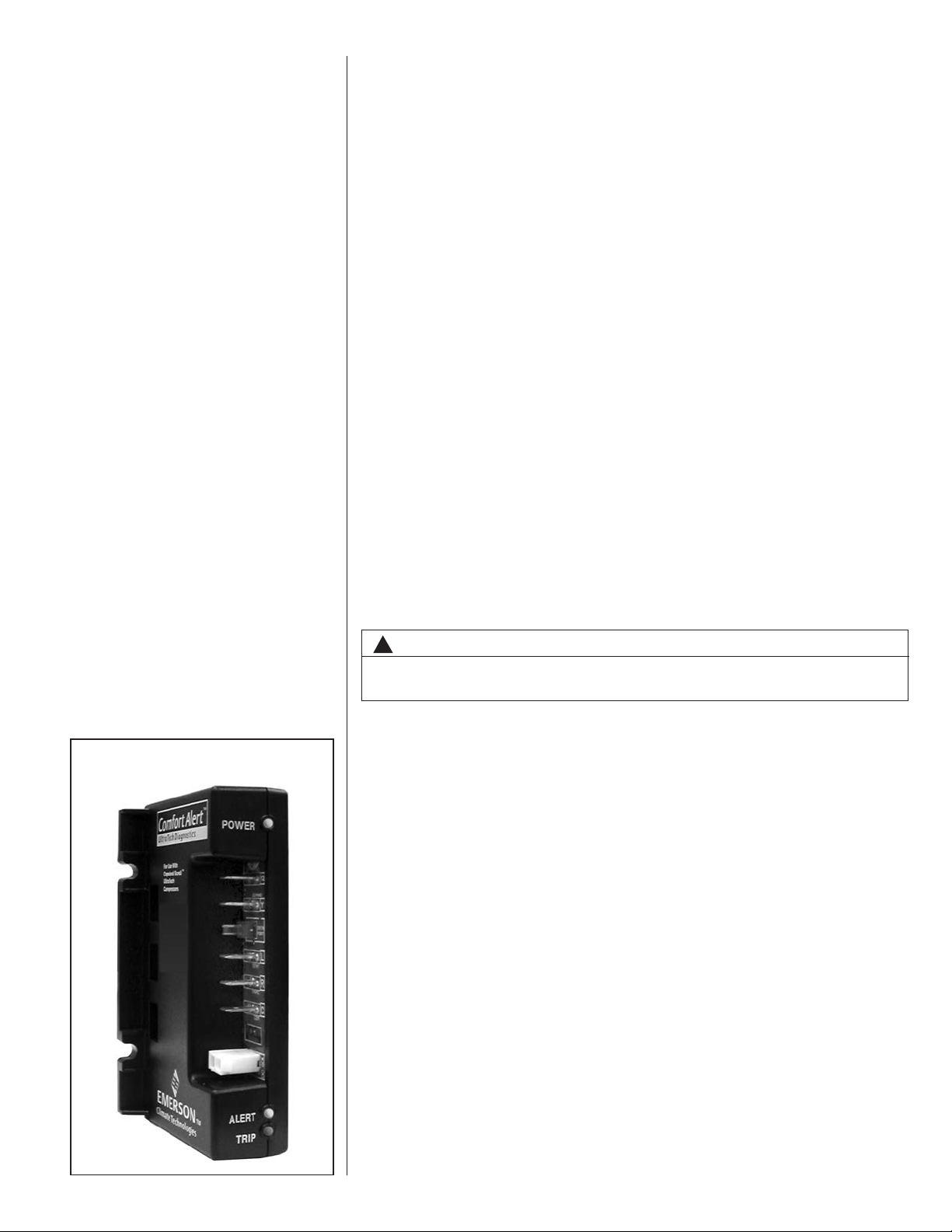
FIGURE 1
LED DESCRIPTION
Manifold Hoses:
-Service Pressure Rating of 800 PSIG
Recovery Cylinders:
-400 PSIG Pressure Rating
-Dept. of Transportation 4BA400 or BW400
!
CAUTION
R-410A systems operate at higher pressures than R-22 systems. Do not use
R-22 service equipment or components on R-410A equipment.
D. COMFORT ALERT™ SYSTEM (2-STAGE MODELS ONLY)
1. Comfort Alert™
The Comfort Alert™ diagnostics module is for troubleshooting air conditioning system failures. By monitoring and analyzing data from the compressor and the thermostat demand, the module can accurately detect the cause of electrical and system-related failures without any external sensors. A flashing LED indicator communicates the ALERT code and guides the service technician more quickly and accurately to the root cause of a problem.
POWER LED (Green): indicates voltage is present at the power connection of the
module.
ALERT LED (Yellow): communicates an abnormal system condition through a
unique flash code. The ALERT LED will flash a number of times consecutively,
pause and then repeat the process. The number of consecutive flashes, defined
as the Flash Code, correlates to a particular abnormal condition. Detailed
descriptions of specific ALERT Flash Codes are shown in the Comfort Alert
Diagnosis Chart in this manual.
TRIP LED (Red): indicates there is a demand signal from the thermostat but no
current to the compressor is detected by the module. The TRIP LED typically
indicates the compressor internal overload protector is open or may indicate
missing high voltage supply power to the compressor.
When an abnormal system condition occurs, the Comfort Alert module displays the
appropriate ALERT and/or TRIP LED. The yellow ALERT LED will flash a number
7
Page 8
of times consecutively, pause and then repeat the process. To identify a Flash
Code number, count the number of consecutive flashes.
IMPORTANT: Every time the module powers up, the last ALERT Flash Code that
occurred prior to shut down is displayed for one minute. The module will continue to
display the flash code until the condition returns to normal or if 24VAC power is
removed from the module.
The control box cover allows access to the Comfort Alert™ status LEDs. An abbreviated Comfort Alert™ diagnostic chart is provided on the control box cover.
2. High Pressure Control (HPC)
The high pressure control (HPC) keeps the compressor from operating in pressure
ranges, which can cause damage to the compressor. This is an auto-reset control that
opens near 610 PSIG and closes once the system pressure drops below 420 PSIG.
The high pressure control is wired in the 24VAC side of the control circuitry.
3. Low Pressure Control (LPC)
The low pressure control (LPC) keeps the compressor from operating in pressure
ranges that can cause damage to the compressor. This is an auto-reset control that
opens near 90 PSIG and closes once the system pressure rises above 135 PSIG.
The low pressure control is wired in the common side of the control circuitry.
4. Comfort Alert With Active Protection
A two-stage cooling thermostat is required for proper unit operation.
Manufacturer recommends the use of thermostats that provide active compressor pro-
tection via the L terminal when the Comfort-Alert module on the unit is connected to the
L terminal on the thermostat.
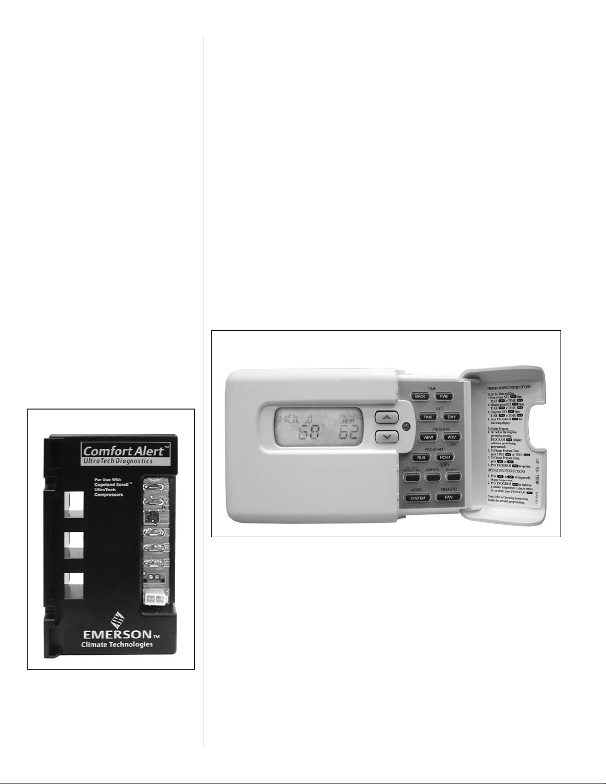
FIGURE 3
FIGURE 2
WHITE-RODGERS 90-SERIES THERMOSTAT
8
Page 9

The Comfort Alert diagnostics module diagnoses system and electrical problems in
the air conditioning system. Abnormal conditions are indicated by flashing
ALERT codes on the yellow LED on the Comfort Alert module. The flash codes are
transmitted to the thermostat when the L terminal on the Comfort Alert Module is
connected to the L terminal on the thermostat. The White-Rodgers 1F95-CA397
thermostat displays a CHECK SYSTEM icon that flashes at the same rate as the yellow
ALERT LED on the Comfort Alert module. Turn this feature ON to achieve
protection, enabling the thermostat to identify certain fault codes when compressor damage is possible and react to those codes by turning the compressor off.
NOTE: The Comfort Alert™ module does not provide safety protection! It does not disconnect power from the unit.
Comfort Alert™ Flash Codes
1 – Long Run Time
2 – System Pressure Trip
3 – Short Cycling
4 – Locked Rotor
5 – Open Circuit
6 – Open Start Circuit
7 – Open Run Circuit
8 – Welded Contactor
9 – Low Voltage
See Figures 61 and 62 (Comfort Alert Diagnostic Charts) for more troubleshooting information.
Active protection occurs under the following conditions:
1) Flash Code 2 - System Pressure Trip
Condition: Four consecutive compressor protector trips occur where the
average run time until trip is between 1 minute and 15 minutes
Possible causes:
Active Thermostat Reaction:
2) Flash Code 3 - Short Cycling
Condition: A pattern of short cycling emerges where the run time for the
previous four cycles is less than three minutes each.
Possible causes:
Active Thermostat Reaction:
Low suction pressure
• Low pressure switch is open
• Low system charge
Blocked condenser coil
Restricted condenser air flow
The thermostat will cycle the system ON for 5 minutes and OFF for
five minutes to verify system fault. If this ON/OFF cycling repeats for
30 ten-minute cycles, the thermostat concludes there is a system
problem and implements a hard lockout.
High head pressure
• High pressure switch is open
• System overcharged
• Non-condensables in system
Faulty thermostat
Intermittent contactor
The thermostat will cycle the system ON for 5 minutes and OFF for
five minutes to verify the system fault. If this ON/OFF cycling repeats for
30 ten-minute cycles, the thermostat concludes there is a system
problem and implements a hard lockout.
9
Page 10

3) Flash Code 4 - Locked Rotor
Condition: The compressor internal overload trips where the average run
time is less than 15 seconds.
Possible causes:
Active Thermostat Reaction:
4) Flash Code 6 - Open Start Circuit
Condition: Current is detected in the run circuit but not in the start circuit.
Possible causes:
Bad run capacitor
Low line voltage
Excessive liquid refrigerant in compressor
Compressor bearings are seized
Faulty hard start components
The thermostat implements a hard lockout once this error is sensed.
Bad run capacitor
Open circuit in compressor start wiring or connections.
Compressor start winding is damaged
Active thermostat reaction:
5) Flash Code 7 - Open Run Circuit
Condition: Open circuit in compressor run wiring or connections.
Compressor run winding is damaged.
Active Thermostat Reaction:
Resetting the White-Rodgers Thermostat After a Hard Lockout
The White-Rodgers thermostat will automatically reset after a hard lockout once the
Comfort Alert trouble code has been cleared.
The thermostat implements a hard lockout after 3 hours.
The thermostat implements a hard lockout after 3 hours.
10
Page 11
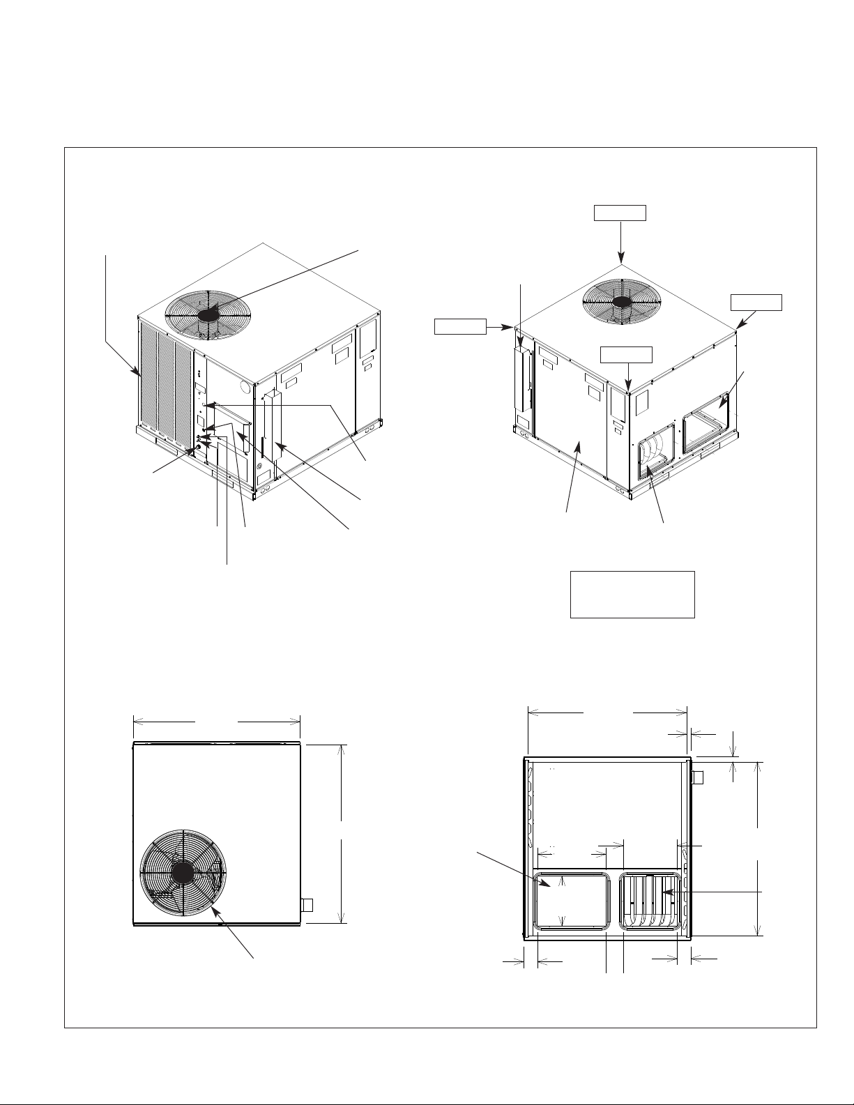
V. UNIT DIMENSIONS
FOR CLEARANCES
SEE FIGURE 4.
FIGURE 4
OUTDOOR COIL
PROTECTIVE GRILLE
OUTDOOR FAN GRILLE
AND COMPRESSOR ACCESS
29% ± 2%
FLUE
EXHAUST
30% ± 2%
20% ± 2%
21% ± 2%
SIDE
RETURN
DUCT
OPENING
THREADED
PVC CONDENSATE
DRAIN CONNECTION
(3/4 NPT)
SUCTION PRESSURE
SERVICE PORT
LIQUID PRESSURE
SERVICE PORT
TOP VIEW
479⁄16”
FIELD CONTROL
WIRE ENTRANCE
FIELD POWER
WIRE ENTRANCE
FLUE EXHAUST
HOOD
COMBUSTION AIR
INLET HOOD
5013⁄16”
BOTTOM
RETURN
DUCT
OPENING
BLOWER/EVAPORATOR
ACCESS PANEL
CORNER WEIGHTS
% OF TOTAL UNIT
BOTTOM VIEW
451⁄16”
INSIDE
191⁄2”
141⁄4”
TYP.
SIDE SUPPLY DUCT
OPENING
WEIGHT
13⁄16”
TYP.
153⁄8”
11⁄2”
TYP.
497⁄16”
INSIDE
BOTTOM
SUPPLY
DUCT
OPENING
OUTDOOR FAN
GRILLE & COMPRESSOR
ACCESS
313⁄16”
33⁄16”
49⁄10”
11
Page 12
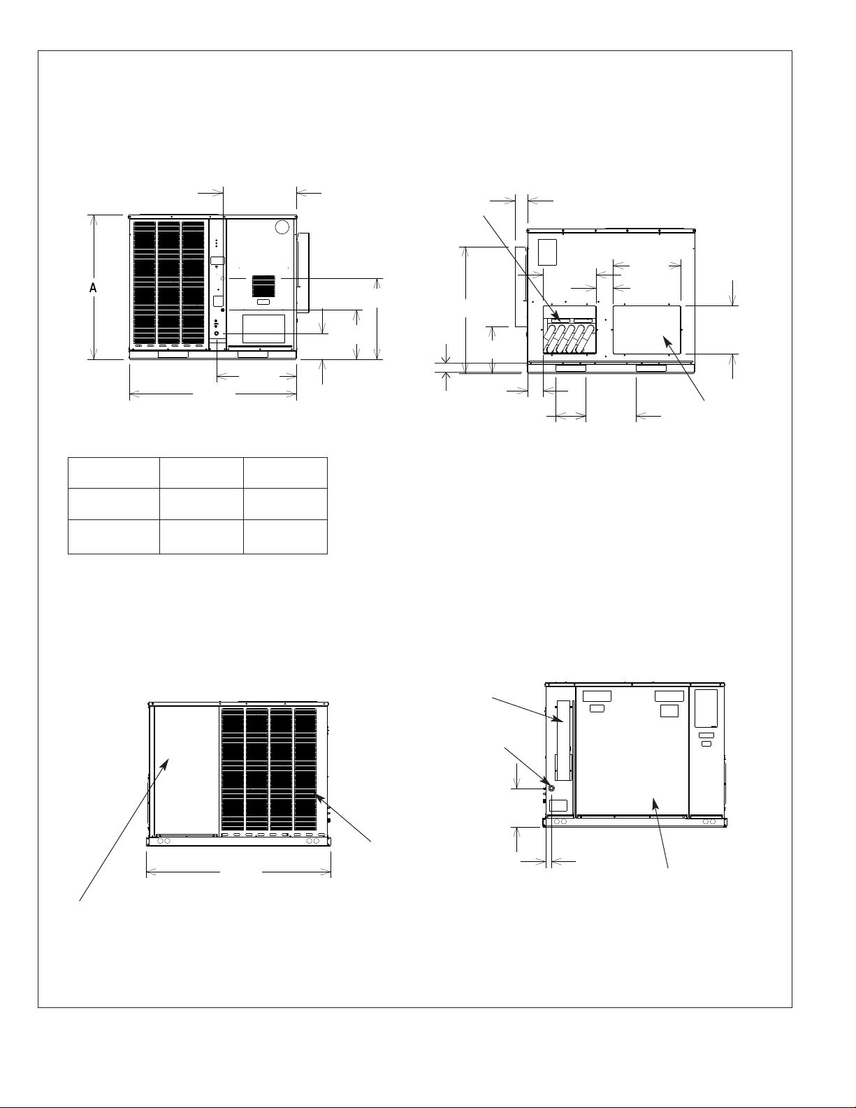
FIGURE 4 (CONTINUED)
MODELS
RRNL & RRPL
B024, B030,
B036
B042, B048,
B060, C060
FRONT VIEW
471⁄2”
MODEL
RRRL
B024
B036, B048,
B060
207⁄8”
2211⁄16”
HEIGHT
“A”
3515⁄16”
41
75⁄16”
227⁄8”
1315⁄16”
21⁄2”
SIDE
SUPPLY
DUCT
OPENING
3515⁄16”
BACK VIEW
39⁄16”
15”
191⁄8”
47⁄8”
131⁄4”
47⁄16”
81⁄2”
TYP.
SHOWN WITH DUCT COVERS REMOVED.
143⁄16”
TYP.
133⁄4”
TYP.
SIDE
RETURN
DUCT
OPENING
FILTER ACCESS PANEL
(FOR UNIT MOUNTED FILTER
ACCESSORY)
SIDE VIEW
527⁄16”
OUTDOOR
COIL PROTECTIVE
GRILLE
SIDE VIEW
FLUE
EXHAUST
HOOD
GAS
SUPPLY
ENTRANCE
1015⁄16”
111⁄16”
BLOWER/
EVAPORATOR
ACCESS PANEL
12
Page 13
VI. INSTALLATION
A. GENERAL
1. PRE-INSTALLATION CHECK-POINTS — Before attempting any installation, carefully consider the following points:
Structural strength of supporting members
(Rooftop Installation)
Clearances and provision for servicing
Power supply and wiring
Gas supply and piping
Air duct connections and sizing
Drain facilities and connections
Location for minimum noise and vibration
2. LOCATION CONSIDERATIONS (CORROSIVE ENVIRONMENT)
The metal parts of this unit may be subject to rust or deterioration if exposed to a
corrosive environment. This oxidation could shorten the equipment’s useful life.
Corrosive elements include, but are not limited to, salt spray, fog or mist in seacoast
areas, sulphur or chlorine from lawn watering systems, and various chemical contaminants from industries such as paper mills and petroleum refineries.
If the unit is to be installed in an area where contaminants are likely to be a
problem, give special attention to the equipment location and exposure.
1. Avoid having lawn sprinkler heads spray directly on the unit cabinet.
2. In coastal areas locate the unit on the side of the building away from the waterfront.
3. Shielding by a fence or shrubs may give some protection.
WARNING
!
DISCONNECT ALL POWER TO UNIT BEFORE STARTING MAINTENANCE.
FAILURE TO DO SO CAN CAUSE ELECTRICAL SHOCK RESULTING IN PERSONAL INJURY OR DEATH.
1. Frequent washing of the cabinet, fan blade and coil with fresh water will remove
most of the salt or other contaminants that build up on the unit.
2. Regular cleaning and waxing of the cabinet with a good automobile polish will provide some protection.
3. Use a good liquid cleaner several times a year to remove matter that will not wash
off with water.
Several different types of protective coatings are offered in some areas. These coatings
may provide some benefit, but the effectiveness of such coating materials cannot be verified by the equipment manufacturer.
The best protection is frequent cleaning, maintenance and minimal exposure to
contaminants.
B. OUTSIDE INSTALLATION
WARNING
!
THESE UNITS ARE DESIGNED CERTIFIED FOR OUTDOOR INSTALLATION
ONLY. INSTALLATION INSIDE ANY PART OF A STRUCTURE CAN RESULT IN
INADEQUATE UNIT PERFORMANCE AS WELL AS PROPERTY DAMAGE.
INSTALLATION INSIDE CAN ALSO CAUSE RECIRCULATION OF FLUE PRODUCTS INTO THE CONDITIONED SPACE RESULTING IN PERSONAL INJURY
OR DEATH.
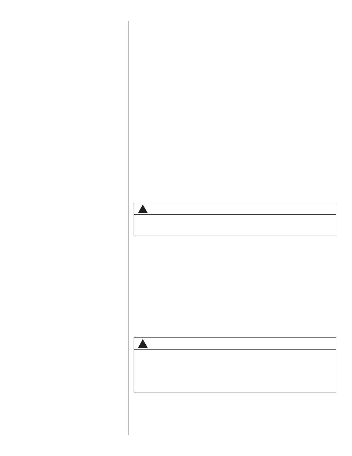
(Typical outdoor slab installation is shown in Figure 5.)
1. Select a location where external water drainage cannot collect around unit.
13
Page 14
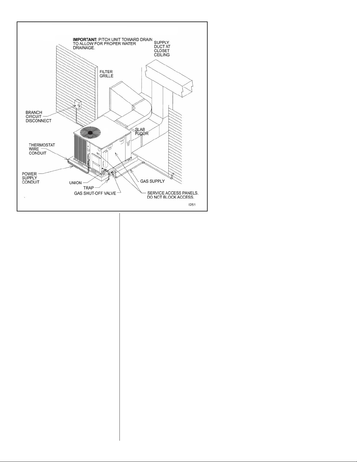
FIGURE 5
OUTSIDE SLAB INSTALLATION. CLOSET DISTRIBUTION SYSTEM. SLAB FLOOR
CONSTRUCTION
2. Provide a slab sufficiently high enough above grade to prevent surface water from
entering the unit. Where snowfall is anticipated, mount the unit above the anticipated maximum snow depth for your area. Do not locate unit in an area where excessive snow drifting may block combustion air inlet.
3. Pitch the slab approximately
1
⁄2” so that the unit will be pitched toward the drain. See
Figure 6.
4. The location of the unit should be such as to provide proper access for inspection
and servicing as shown in Figure 12.
5. Locate unit where operating sounds will not disturb owner or neighbors. The slab
should be isolated from the foundation wall.
6. Locate unit so roof runoff water does not pour directly on the unit. Provide gutter or
other shielding at roof level.
C. ATTACHING EXHAUST AND COMBUSTION AIR INLET HOODS
IMPORTANT: Do not operate this unit without the exhaust and combustion air inlet
hood properly installed. These hoods are shipped in a carton in the return air compartment inside the unit and must be attached when the unit is installed. See Figure 7.
To attach exhaust and combustion air inlet hood:
1. Remove 3 screws securing filter access panel and remove filter access panel. For location of filter access panel, see Figure 4.
2. Remove both exhaust and combustion air inlet hoods from their carton, located inside
the return air compartment.
3. Attach filter access panel.
4. Attach the combustion air inlet hood and the exhaust hood each with 4 screws as shown
in Figure 7. Screws are in parts bag shipped in the burner compartment.
5. Vent the unit using the flue exhaust hood, as supplied from the factory, without alteration
or addition. The only exception is with factory approved additions. Consult your local utility or other authority having jurisdiction for accepted venting techniques.
14
Page 15
FIGURE 6
PITCHING UNIT TO INSURE PROPER CONDENSATE DRAINAGE.
FIGURE 7
COMBUSTION AIR INLET HOOD & EXHAUST HOOD
INSTALLATION
EXHAUST
HOOD W/(4)
SCREWS
I655
COMBUSTION
AIR INLET
HOOD W/(4)
SCREWS
D. COVER PANEL INSTALLATION/CONVERSION PROCEDURE
1. HORIZONTAL TO DOWNFLOW
a. Remove screws and covers from the supply and return bottom sections. NOTE:
Rotate the supply cover 90° and remove.
b. Install gasket (supplied with parts bag) around perimeter of cover on the insulated
side. See Figure 9.
c. Secure covers to the side of the unit using existing screws and those supplied in
the parts bag.
2. DOWNFLOW TO HORIZONTAL
a. Remove screws and covers from the supply and return bottom sections.
b. Install gasket (supplied with parts bag) around perimeter of cover as illustrated in
Figure 8.
c. Install covers in the unit bottom with the insulated side up. NOTE: Supply cover
must be inserted through supply opening with narrow side toward unit. Once
cover is through opening, rotate 90° and slip back flange of cover under tab at the
back of bottom duct opening. See Figure 11.
d. Secure supply cover to base of unit with 2 screws, engaging prepunched holes in
raised duct opening flange.
e. Secure return covers to base of unit with screws engaging prepunched holes in
raised duct opening flange.
WARNING
!
THIS UNIT MUST NOT BE INSTALLED DIRECTLY ON WOOD FLOORING, CLASS
A, CLASS B OR CLASS C ROOF COVERING MATERIALS, OR ANY OTHER COMBUSTIBLE STRUCTURE EXCEPT AS SPECIFIED IN FIGURE 16. FAILURE TO
ADHERE TO THIS WARNING CAN CAUSE A FIRE OR EXPLOSION RESULTING
IN PROPERTY DAMAGE, PERSONAL INJURY OR DEATH.
E.CLEARANCES
The following minimum clearances must be observed for proper unit performance and
serviceability. See Figure 12.
1. Provide 48” minimum clearance at front of the unit. Provide 24” minimum clearance
on right side of unit. If economizer is used, a 24” minimum clearance is required on
15
Page 16
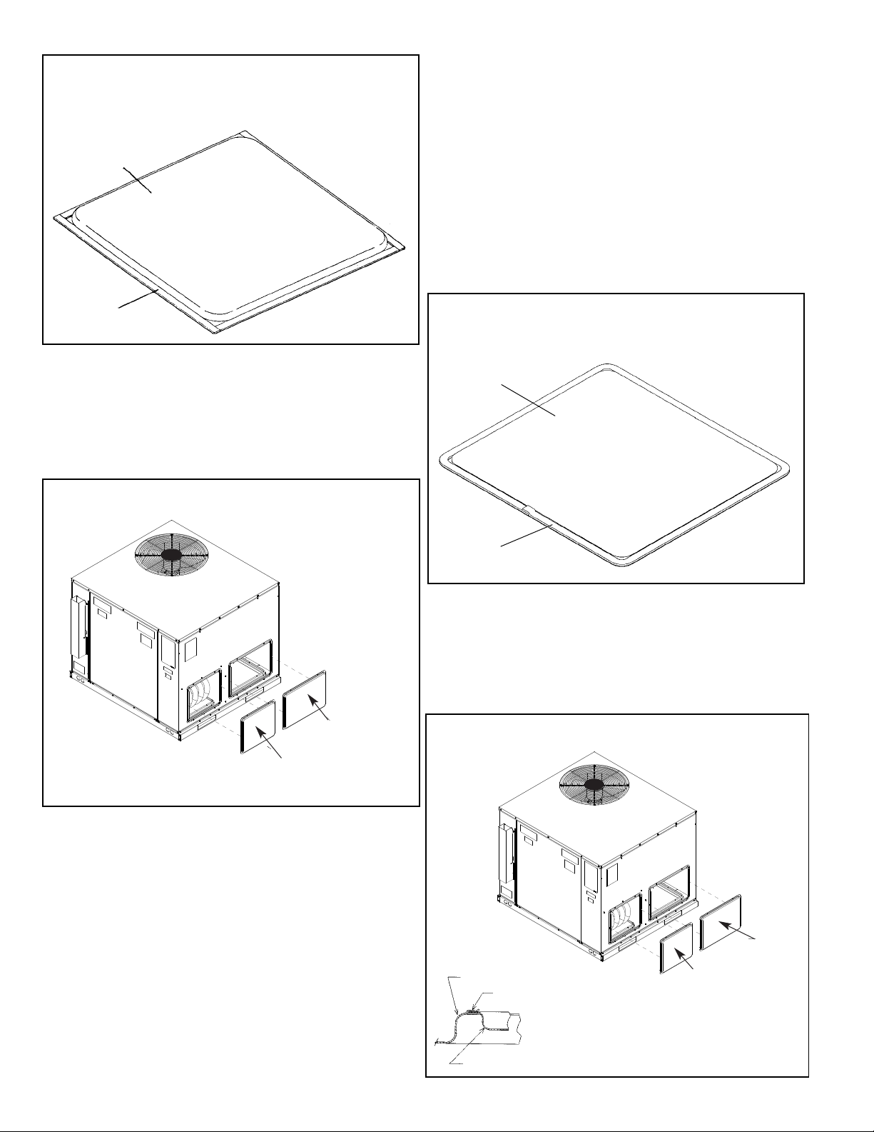
FIGURE 5
COVER GASKET DETAILFOR UNITS SHIPPED FOR DOWNFLOW
APPLICATION BEING CONVERTED TO SIDE DISCHARGE
TAPE
AROUND FLANGE
SUPPLY/RETURN
AIR COVER
FIGURE 6
COVER GASKET DETAILFOR UNITS SHIPPED FOR SIDE DISCHARGE
APPLICATION BEING CONVERTED TO DOWNFLOW
TAPE
AROUND FLANGE
SUPPLY/RETURN
AIR COVER
I654
FIGURE 7
DUCT COVER INSTALLATION SIDE MOUNTING
I264
RETURN
DUCT COVER
(ATTACH WITH 6 SCREWS)
SUPPLY
DUCT COVER
(ATTACH WITH 6 SCREWS)
I
FIGURE 8
DUCT COVER INSTALLATION BASE PAN MOUNTING
I265
BASE PAN
SUPPLYDUCT
COVER
*
(INSULATION
SIDE UP),
ATTACH WITH
TWO SCREWS.
RETURN
DUCT
COVER
(INSULATION
SIDE UP ,
ATTACH
WITH 4
SCREWS)
SUPPLYDUCT
COVER
*
ROTATE SUPPLY COVER 90° AFTER IT IS INSERTED
THROUGH OPENING. SLIP FLANGE OF COVER
UNDER LANCE AT BACK OF BOTTOM SUPPLY DUCT
OPENING. SEE DETAILAT LEFT. THEN SECURE
COVER BY INSTALLING 2 SCREWS USING HOLE
NEAREST THE OUTSIDE OF UNIT.
LANCE AT BACK OF BOTTOM
SUPPLYDUCT OPENING
FIGURE 8
COVER GASKET DETAIL FOR UNITS SHIPPED FOR DOWNFLOW
APPLICATION BEING CONVERTED TO SIDE DISCHARGE
FIGURE 9
COVER GASKET DETAIL FOR UNITS SHIPPED FOR SIDE DISCHARGE
APPLICATION BEING CONVERTED TO DOWNFLOW
FIGURE 10
DUCT COVER INSTALLATION SIDE MOUNTING
FIGURE 11
DUCT COVER INSTALLATION BASE PAN MOUNTING
16
Page 17
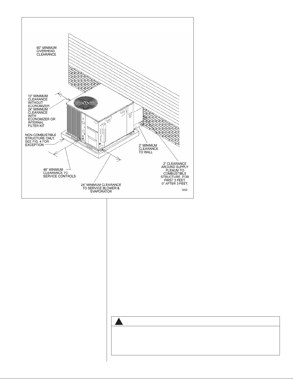
FIGURE 12
CLEARANCES
left side of unit. (See Figure 12.) If no economizer is required, then a 12” clearance
is required on left side of unit.
2. Provide 60” minimum clearance between top of unit and maximum 3 foot overhang.
3. Unit is design certified for 2” minimum clearance between supply duct and a combustible structure for the first 3 feet of duct. 0” clearance is allowed after 3 feet.
F. ROOFTOP INSTALLATION
1. Before locating the unit on the roof, make sure that the roof structure is adequate to
support the weight involved. (See electrical & physical tables in this book for weight
of unit.) THIS IS VERY IMPORTANT AND THE INSTALLER’S RESPONSIBILITY.
2. For rigging and roofcurb details, see Figures 17, 18, and 19.
3. The location of the unit on the roof should be such as to provide proper access for
inspection and servicing.
IMPORTANT: If unit will not be put into service immediately, block off supply and return
air openings to prevent excessive condensation.
G. DUCTWORK
The installing contractor should fabricate ductwork in accordance with local codes. Use
industry manuals as a guide when sizing and designing the duct system. Contact Air
Conditioning Contractors of America, 1513 16th St. N.W., Washington, D.C. 20036.
WARNING
!
DO NOT, UNDER ANY CIRCUMSTANCES, CONNECT RETURN DUCTWORK TO
ANY OTHER HEAT PRODUCING DEVICE SUCH AS FIREPLACE INSERT,
STOVE, ETC. UNAUTHORIZED USE OF SUCH DEVICES MAY RESULT IN FIRE,
CARBON MONOXIDE POISONING, EXPLOSION, PERSONAL INJURY, OR
PROPERTY DAMAGE.
17
Page 18
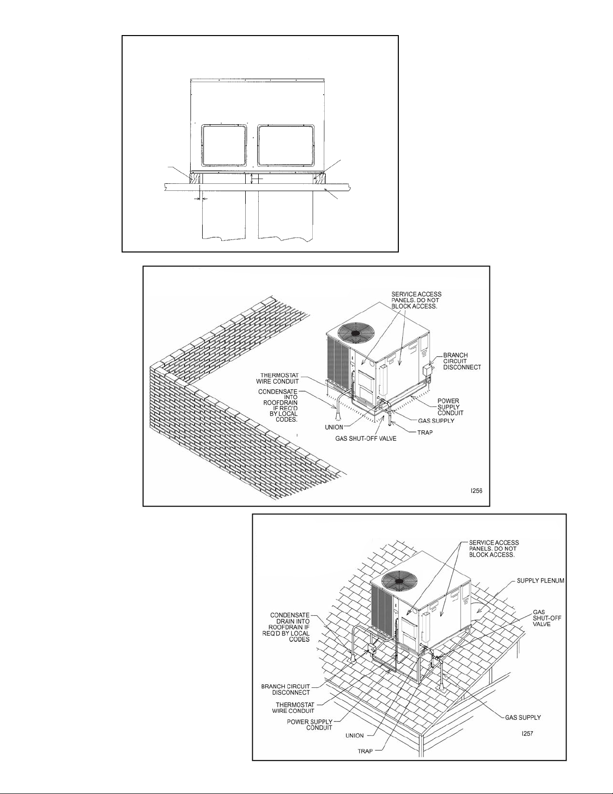
FIGURE 10
EXCEPTION TO NON-COMBUSTIBLE FLOORING REQUIREMENT
I458
BOTH ENDS
MUST BE
OPEN FOR
DOWNFLOW
OR SIDEFLOW
DUCTWORK
TO PROVIDE
VENTILATION
COMBUSTIBLE
STRUCTURE
1” MIN.
NOMINAL
4 x 4 TIMBER
(SIDES ONLY)
SIDEFLOW
SUPPLY
PLENUM
CONNECTION
SUPPLY
PLENUM
(DOWNFLOW)
RETURN PLENUM
(DOWNFLOW)
SIDEFLOW
RETURN PLENUM
CONNECTION
3-1/2” MIN.
FIGURE 13
EXCEPTION TO NON-COMBUSTIBLE FLOORING REQUIREMENT
FIGURE 14
FLAT ROOFTOP INSTALLATION, ATTIC OR DROP CEILING DISTRIBUTING SYSTEM. MOUNTED ON
ROOFCURB, PITCH UNIT TOWARD DRAIN.
18
FIGURE 15
PITCHED ROOFTOP INSTALLATION, ON ANGLE-IRON STAND, SIDE FLOW DUCTWORK,
ATTIC OR DROP CEILING
DISTRIBUTING SYSTEM.
PITCH UNIT TOWARD DRAIN.
Page 19
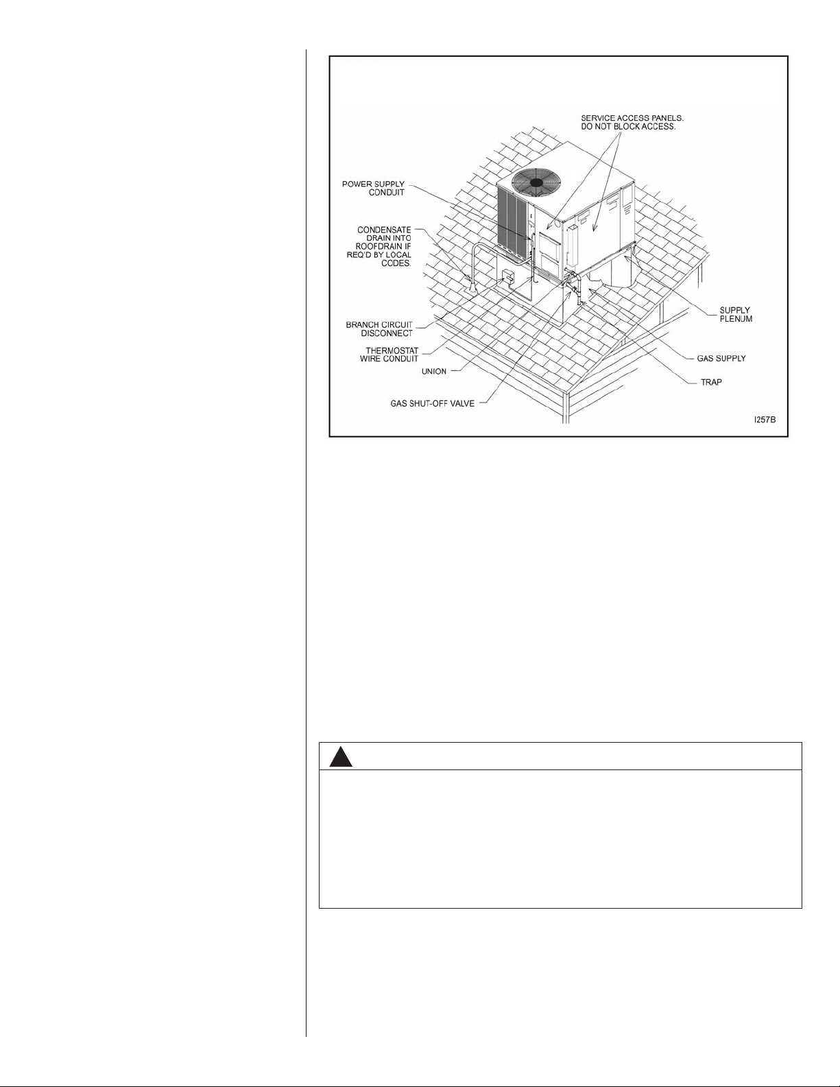
FIGURE 16
PITCHED ROOFTOP INSTALLATION, ON ROOFJACK, DOWNFLOW DUCTWORK, ATTIC OR
DROP CEILING DISTRIBUTING SYSTEM. PITCH UNIT TOWARD DRAIN.
Place the unit as close to the conditioned space as possible allowing clearances as indicated. Run ducts as directly as possible to supply and return outlets. Use of non-flammable weatherproof flexible connectors on both supply and return connections at unit to
reduce noise transmission is recommended.
On ductwork exposed to outside temperature and humidity, use a minimum of 2” of
insulation and a vapor barrier. Distribution system in attic, furred space or crawl space
should be insulated with at least 2” of insulation.
cient for ductwork inside the air conditioned space.
Provide balancing dampers for each branch duct in the supply system. Properly support
ductwork from the structure.
IMPORTANT: In the event that the return air ducts must be run through an “unconfined”
space containing other fuel burning equipment, it is imperative that the user/homeowner
must be informed against future changes in construction which might change this to a
“confined space.” Also, caution the user/homeowner against any future installation of
additional equipment (such as power ventilators, clothes dryers, etc., within the existing
unconfined and/or confined space which might create a negative pressure within the
vicinity of other solid, liquid, or gas fueled appliances.
1
⁄2” to 1” thick insulation is usually suffi-
H. RETURN AIR
WARNING
!
NEVER ALLOW PRODUCTS OF COMBUSTION OR THE FLUE PRODUCTS TO
ENTER THE RETURN AIR DUCTWORK, OR THE CIRCULATING AIR SUPPLY.
ALL RETURN DUCTWORK MUST BE ADEQUATELY SEALED AND SECURED
TO THE FURNACE WITH SHEET METAL SCREWS, AND JOINTS TAPED. ALL
OTHER DUCT JOINTS MUST BE SECURED WITH APPROVED CONNECTIONS
AND SEALED AIRTIGHT.
FAILURE TO PREVENT PRODUCTS OF COMBUSTION FROM BEING CIRCULATED INTO THE LIVING SPACE CAN CREATE POTENTIALLY HAZARDOUS
CONDITIONS, INCLUDING CAROBON MONOXIDE POISONING THAT COULD
RESULT IN PERSONAL INJURY OR DEATH.
19
Page 20
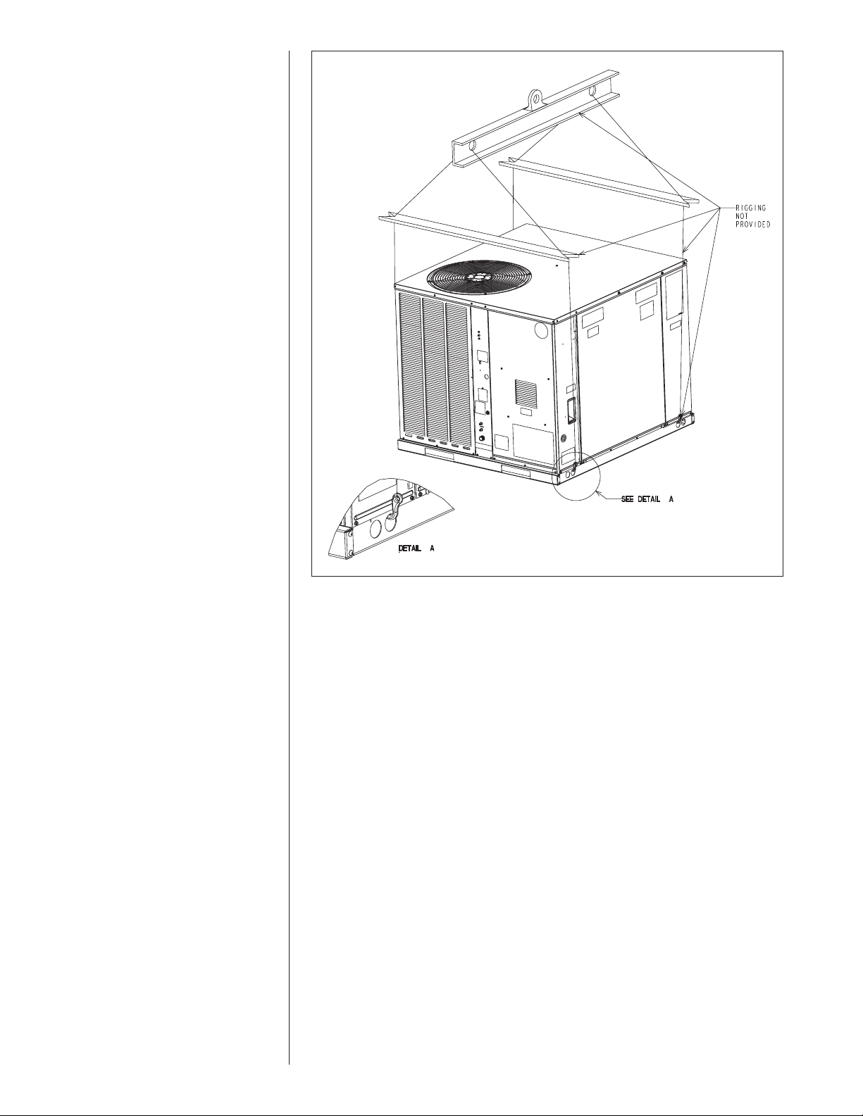
FIGURE 17
LIFTING DETAIL.
I
. FILTERS
The installer must install field supplied filters in the return air duct. A field installed filter
grille is recommended for easy and convenient access to the filters for periodic inspection and cleaning. Filters must have adequate face area for the rated air quantity of the
unit. See air delivery tables for recommended filter size. A field installed internal filter kit
RXRY-B01 is available.
20
Page 21
I342
RETURN PLENUM
16
1
/2
MAX.
20
1
/2 MAX.
16
3
/8 MAX.
INSULATION
PANELS
NAILING
STRIP
CAULK ALL
JOINTS
WATERTIGHT
SUPPLY
PLENUM
DUCT
FLANGE
(NOT TO
EXCEED 1()
ROOFCURB
FIGURE 15
ROOFCURB
I255
**BY CONTRACTOR
**FOR INSTALLATION OF DUCT AS SHOWN, USE RECOMMENDED
DUCT SIZES FROM ROOFCURB INSTALLATION INSTRUCTIONS. FOR
DUCT FLANGE ATTACHMENT TO UNIT, SEE UNIT INSTALLATION
INSTRUCTIONS (FIGURE 1) FOR SIZE OF DUCT OPENINGS.
ROOFTOP UNIT
TIE DOWN SCREW *
ROOFCURB
ROOF FLASHING
*
ROOFING *
CANT STRIP *
ROOF DECK *
GASKET
NAILING STRIP
INSULATION
*
INSULATION *
** DUCT *
FIGURE 16
ROOFCURB
FIGURE 18
ROOFCURB
FIGURE 19
ROOFCURB
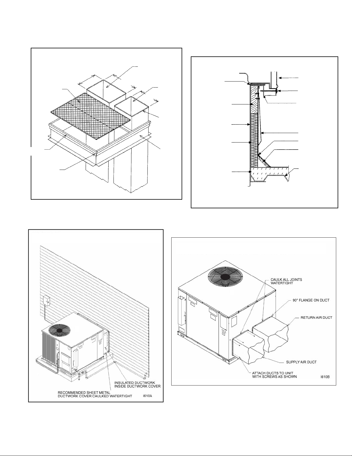
FIGURE 20
DUCTWORK COVER INSTALLATION DETAIL
FIGURE 21
RESIDENTIAL ROOFTOP DUCTWORK INSTALLATION DETAIL.
21
Page 22

VII.GAS SUPPLY, CONDENSATE DRAIN AND
FIGURE 19
SUGGESTED GAS PIPING
FROM GAS
METER
*
Factory supplied grommet must be utilized.
MANUAL GAS
SHUT-OFF
VALVE
UNIT GAS SUPPLY
CONNECTION
*
ROOF OR GROUND LEVEL INSTALLATION
Nominal
Iron Pipe
Size,
Inches
Equivalent Length of Pipe, Feet
10 20 30 40 50 60 70 80
1
/2 132 92 73 63 56 50 46 43
3
/4 278 190 152 130 115 105 96 90
1520350285245215195180170
11/4 1,050 730 590 500 440 400 370 350
11/2 1,600 1,100 890 760 670 610 560 530
TABLE 1
GAS PIPE CAPACITYTABLE (CU. FT./HR.)
VII.PIPING
A. GAS CONNECTION
IMPORTANT: Connect this unit only to gas supplied by a commercial utility.
1. Install gas piping in accordance with local codes and regulations of the local utility
company. In the absence of local codes, the installation must conform to the specifications of the National Fuel Gas Code, ANSI Z223.1 - latest edition.
NOTE: The use of flexible gas connectors is not permitted.
NOTE: The Commonwealth of Massachusetts requires the gas shut-off valve to be
a T-handle gas cock.
2. Connect the gas line to the gas pipe inlet opening provided into the 1/2” inlet valve.
See Figure 5 for typical piping.
3. Size the gas line to the furnace adequate enough to prevent undue pressure drop
and never less than 1/2”.
4. Install a drip leg or sediment trap in the gas supply line as close to the unit as possible.
5. Install an outside ground joint union to connect the gas supply to the control assembly at the burner tray.
6. Gas valves have been factory installed. Install a manual gas valve where local codes
specify a shut-off valve outside the unit casing. (See Figure 22.)
7. Make sure piping is tight. A pipe compound resistant to the action of liquefied
petroleum gases must be used at all threaded pipe connections.
8. IMPORTANT: Any additions, changes or conversions required for the furnace to satisfactorily meet the application should be made by a qualified installer, service
agency or the gas supplier, using factory-specified or approved parts. In the commonwealth of Massachusetts, installation must be performed by a licensed plumber
or gas fitter for appropriate fuel.
IMPORTANT: Disconnect the furnace and its individual shutoff valve from the gas supply piping during any pressure testing of that system at test pressures in excess of 1/2
psig or isolate the system from the gas supply piping system by closing its individual
manual shutoff valve during any pressure testing of this gas supply system at pressures
equal to or less than 1/2 PSIG.
FIGURE 22
SUGGESTED GAS PIPING
22
Page 23
WARNING
!
DO NOT USE AN OPEN FLAME TO CHECK FOR LEAKS. THE USE OF AN OPEN
FLAME CAN RESULT IN FIRE, EXPLOSION, PROPERTY DAMAGE, PERSONAL
INJURY OR DEATH.
TO CHECK FOR GAS LEAKS, USE A SOAP AND WATER SOLUTION OR OTHER
APPROVED METHOD. DO NOT USE AN OPEN FLAME.
IMPORTANT: Check the rating plate to make certain the appliance is equipped to burn
the type of gas supplied. Care should be taken after installation of this equipment that
the gas control valve not be subjected to high gas supply line pressure.
In making gas connections, avoid strains as they may cause noise and damage the controls. A backup wrench is required to be used on the valve to avoid damage.
The capacities of gas pipe of different diameters and lengths in cu. ft. per hr. with pressure drop of 0.5 in. and specific gravity of 0.60 (natural gas) are shown in Table 2.
After determining the pipe length, select the pipe size which will provide the minimum
cubic feet per hour re quired for the gas input rating of the furnace. By formula:
Gas Input of Furnace
Cu. Ft. Per Hr. Required =
The gas input of the furnace is marked on the furnace rating plate. The heating value of
the gas (BTU/FT
L.P. gas supplier.
(BTU/HR)
Heating Value of Gas
3
(BTU/FT
3
) may be determined by consulting the local natural gas utility or the
)
B. LP CONVERSION SINGLE STAGE GAS HEAT
WARNING
!
THIS UNIT IS EQUIPPED AT THE FACTORY FOR USE ON NATURAL GAS ONLY.
CONVERSION TO LP GAS REQUIRES A SPECIAL KIT SUPPLIED BY THE DISTRIBUTOR OR MANUFACTURER. MAILING ADDRESSES ARE LISTED ON THE
FURNACE RATING PLATE, PARTS LIST AND WARRANTY. FAILURE TO USE
THE PROPER CONVERSION KIT CAN CAUSE FIRE, CARBON MONOXIDE POISONING, EXPLOSION, PERSONAL INJURY, PROPERTY DAMAGE OR DEATH.
Convert the valve to use liquefied petroleum (LP) gas by replacing the pressure regulator
spring with the conversion kit spring. This LP kit spring allows the regulator to maintain the
proper manifold pressure for LP gas. The correct burner LP orifices are included in the kit.
See Figure 23.
NOTE: Order the correct LP conversion kit from the furnace manufacturer. See
Conversion Kit Index shipped with unit for proper LP kit number. Furnace conversion to LP gas must be performed by a qualified technician.
FIGURE 23
23
Page 24
C. LP CONVERSION TWO STAGE GAS HEAT
Maximum capacity of pipe in thousands of BTU per hour of undiluted liquefied petroleum
gases (at 11 inches water column inlet pressure).
(Based on a Pressure Drop of 0.5 Inch Water Column)
TABLE 2
LP GAS PIPE CAPACITY TABLE (CU. FT./HR.)
Nominal
Iron Pipe
Size, Inches
10 20 30 40 50 60 70 80 90 100 125 150
275 189 152 129 114 103 96 89 83 78 69 63
567 393 315 267 237 217 196 182 173 162 146 132
1,071 732 590 504 448 409 378 346 322 307 275 252
2,205 1,496 1,212 1,039 913 834 771 724 677 630 567 511
3,307 2,299 1,858 1,559 1,417 1,275 1,181 1,086 1,023 976 866 787
6,221 4,331 3,465 2,992 2,646 2,394 2,205 2,047 1,921 1,811 1,606 1,496
1/2
3/4
1
1-1/4
1-1/2
2
Length of Pipe, Feet
Example (LP): Input BTU requirement of unit, 150,000
Equivalent length of pipe, 60 ft. = 3/4” IPS required.
WARNING
!
THIS UNIT IS EQUIPPED AT THE FACTORY FOR USE ON NATURAL GAS ONLY.
CONVERSION TO LP GAS REQUIRES A SPECIAL KIT SUPPLIED BY THE DISTRIBUTOR OR MANUFACTURER. MAILING ADDRESSES ARE LISTED ON THE
FURNACE RATING PLATE, PARTS LIST AND WARRANTY. FAILURE TO USE
THE PROPER CONVERSION KIT CAN CAUSE FIRE, CARBON MONOXIDE POISONING, EXPLOSION, PERSONAL INJURY, PROPERTY DAMAGE OR DEATH.
Convert the valve to use liquefied petroleum (LP) gas by replacing with the gas valve supplied in the conversion kit. The LP gas valve maintains the proper manifold pressure for LP
gas. The correct burner LP orifices are included in the kit.
IMPORTANT: To remove the natural gas valve, remove the four screws securing the manifold pipe to the burner tray. Remove the manifold pipe with gas valve attached.
NOTE: Order the correct LP conversion kit from the furnace manufacturer. See
Conversion Kit Index shipped with unit for proper LP kit number. Furnace conversion to LP gas must be performed by a qualified technician.
D. NOx MODELS
When converting units equipped with NOx inserts to LP gas, the stainless steel mesh
inserts in the entrance of the tubular exchangers are not required to meet SCAQMD NOx
emission levels. Carefully remove these inserts before firing this furnace on LP gas. This
furnace is not designed to operate on LP gas with the NOx inserts in place.
Step by step instructions on removing the NOx inserts and retaining rod are included in the
Conversion Kit Installation Instructions.
E. ADJUSTING OR CHECKING FURNACE INPUT
– Natural Gas Line Pressure 5” - 10.5” W.C.
– LP Gas Line Pressure 11” - 13” W.C.
– Natural Gas Manifold Pressure 3.5” W.C
– LP Gas Manifold Pressure - 10” W.C.
Supply and manifold pressure taps are located on the gas valve body 1/8” N.P.T.
Use a properly calibrated manometer gauge for accurate gas pressure readings.
Only small variations in the gas flow should be made by means of the pressure regulator
adjustment. Furnaces functioning on LP gas must be set by means of the tank or branch
supply regulators. The furnace manifold pressure should be set at 10” W.C. at the gas control valve.
To adjust the pressure regulator, remove the regulator cap and turn the adjustment screw
clockwise to increase pressure or counterclockwise to decrease pressure. Then replace
the regulator cap securely.
24
Any necessary major changes in the gas flow rate should be made by changing the size of
the burner orifices. To change orifice spuds, shut off the manual main gas valve and
remove the gas manifold.
For elevations up to 2,000 feet, rating plate input ratings apply. For high altitudes (elevations
over 2,000 ft.), see conversion kit index 92-21519-47 for derating and orifice spud sizes.
Check of input is important to prevent over-firing of the furnace beyond its designrated input. NEVER SET INPUT ABOVE THAT SHOWN ON THE RATING PLATE. Use
the following table or formula to determine input rate.
Cu. Ft. Per Hr. Required =
Heating Value of Gas
(BTU/Cu. Ft.) x 3600
Time in Seconds
(for 1 Cu. Ft.) of Gas
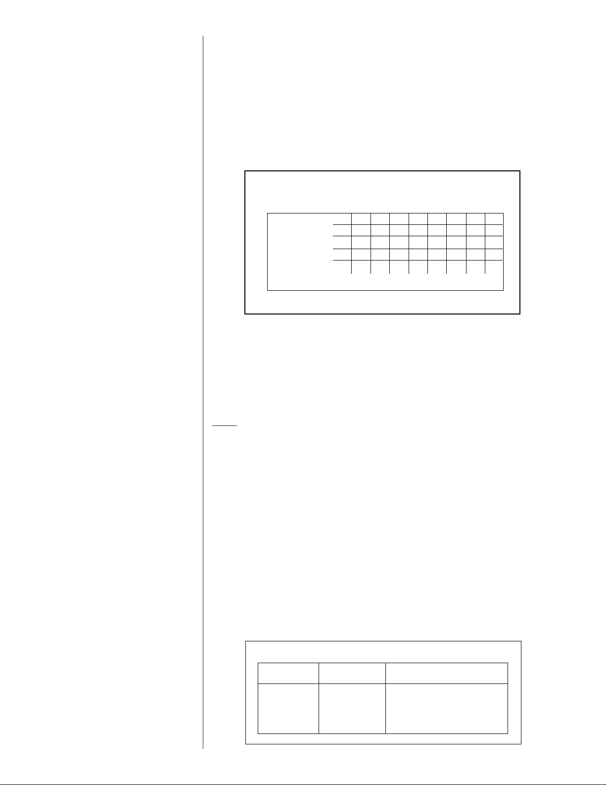
Page 25
Start the furnace and measure the time required to burn one cubic foot of gas. Prior to
ONE 1 21 1 30 1 34 1 39 3 45
40,000
TEN 13 30 15 0 15 36 16 30 37 30
ONE 0 54 1 0 1 3 1 6 2 30
60,000
TEN 9 0 10 0 10 24 11 0 25 0
ONE 0 41 0 45 0 47 0 50 1 53
80,000
TEN 6 45 7 30 7 48 8 15 18 45
ONE 0 33 0 36 0 38 0 40 1 30
100,000
TEN 5 24 6 0 6 15 6 36 15 0
METER TIME IN MINUTES AND SECONDS FOR NORMAL
INPUT RATING OF FURNACES EQUIPPED FOR NATURAL
OR LP GAS
INPUT
BTU/HR
METER
SIZE
CU. FT.
HEATING VALUE OF GAS BTU PER CU. FT.
900 1000 1040 1100 2500
MIN. SEC. MIN. SEC. MIN. SEC. MIN. SEC. MIN. SEC.
TABLE 3
checking the furnace input, make certain that all other gas appliances are shut off, with
the exception of pilot burners. Time the meter with only the furnace in operation.
IMPORTANT NOTE FOR ALTITUDES ABOVE 2,000 FEET (610 METERS): The main
burner orifices in your furnace and in these kits are sized for the nameplate input and
intended for installations at elevations up to 2,000 feet in the USA or Canada, or for elevations of 2,000 - 4,500 feet (610 -1,373 meters) in Canada if the unit has been derated
at the factory. For elevations above 2,000 feet (610 meters) IN THE USA ONLY (see
ANSI-Z223.1), the burner orifices must be sized to reduce the input 4% for each 1,000
feet (305 meters) above sea level.
NOTICE: DERATING OF THE HEATING INPUT FOR HIGH ALTITUDE IN THE FIELD
IS UNLAWFUL IN CANADA (REFER TO CAN/CGA 2.17). UNITS INSTALLED IN
ALTITUDES GREATER THAN 2,000 FEET (610 METERS) MUST BE SHIPPED FROM
THE FACTORY OR FROM A FACTORY AUTHORIZED CONVERSION STATION
WITH THE HEATING INPUT DERATED BY 10% SO AS TO OPERATE PROPERLY IN
ALTITUDES FROM 2,000 - 4,500 FEET (610 - 1,373 METERS).
F. CONDENSATE DRAIN
The evaporator coil condensate drain ends with a threaded 3/4” nominal PVC stub. A
trap is built in for proper condensate drainage and to prevent debris from being drawn
into the unit. Do not connect the drain to a closed sewer line. Connection to a vented
sewer line is allowed. It is recommended that a PVC cement not be used so that the
drain line can be easily cleaned in the future.
IMPORTANT: DO NOT INSTALL AN EXTERNAL TRAP. DOING SO CAN CAUSE
IMPROPER DRAINAGE OF THE CONDENSATE AND RESULT IN FLOODING WITHIN THE UNIT.
VIII.WIRING
A. POWER SUPPLY
WARNING
!
TURN OFF THE MAIN ELECTRICAL POWER AT THE BRANCH CIRCUIT DISCONNECT CLOSEST TO THE UNIT BEFORE ATTEMPTING ANY WIRING. FAILURE
TO DO SO CAN CAUSE ELECTRICAL SHOCK RESULTING IN PERSONAL
INJURY OR DEATH.
25
Page 26
1. All wiring should be made in accordance with the National Electrical Code.
200 6 4 4 4 3 3 2 2
150 8 6 6 4 4 4 3 3
100 10 8 8 6 6 6 4 4
50 14 12 10 10 8 8 6 6
15 20 25 30 35 40 45 50
TABLE 4
BRANCH CIRCUIT COPPER WIRE SIZE
(BASED ON 1% VOLTAGE DROP)*
SUPPLY WIRE
LENGTH-FEET
*Taken from National Electric Code
BRANCH CIRCUIT AMPACITY
AWG Copper AWG Aluminum Connector Type and Size
Wire Size Wire Size (or equivalent)
#12 #10 T & B Wire Nut PT2
#10 # 8 T & B Wire Nut PT3
# 8 # 6 Sherman Split Bolt TSP6
# 6 # 4 Sherman Split Bolt TSP4
# 4 # 2 Sherman Split Bolt TSP2
TABLE 5
Consult the local power company to determine the availability of sufficient power to
operate the unit. Check the voltage at power supply to make sure it corresponds to
the unit’s RATED VOLTAGE REQUIREMENT. Install a branch circuit disconnect
near the rooftop, in accordance with the N.E.C., C.E.C. or local codes.
2. It is important that proper electrical power is available at the unit. Voltage should not
vary more than 10% from that stamped on the unit nameplate. On three phase units,
phases must be balanced within 3%.
3. For branch circuit wiring (main power supply to unit disconnect), the minimum wire size
for the length of run can be determined from Table 4 using the circuit ampacity found on
the unit rating plate. Use the smallest wire size allowable in Table 4 from the unit disconnect to unit. The disconnect must be in sight and readily accessible of the unit.
NOTES:
1. Wire size based on 60°C rated wire insulation and 30°C Ambient Temp. (86°F).
2. For more than 3 conductors in a raceway or cable, see the N.E.C. for derating the
ampacity of each conductor.
When installed, the unit must be electrically grounded in accordance with local
codes or, in the absence of local codes, with the National Electrical Code,
ANSI/NFPA 70, if an external electrical source is utilized.
IMPORTANT: THIS UNIT IS AP PROVED FOR USE WITH COPPER CONDUCTORS
CONNECTED TO UNIT CONTACTOR.
ONLY
WARRANTY MAY BE JEOPARDIZED IF ALUMINUM WIRE IS CONNECTED TO
UNIT CONTACTOR.
Special instructions apply for power wiring with aluminum conductors: Warranty
is void if connections are not made per instructions.
Attach a length (6” or more) of recommended size copper wire to the unit contactor terminals L1 and L3 for single phase, L1, L2 and L3 for three phase.
Select the equivalent aluminum wire size from the tabulation below:
Splice copper wire pigtails to aluminum wire with U.L. recognized connectors for copper-
aluminum splices. Please exercise the following instructions very carefully to obtain a
positive and lasting connection:
1. Strip insulation from aluminum conductor.
2. Coat the stripped end of the aluminum wire with the recommended inhibitor, and
wire brush the aluminum surface through inhibitor. INHIBITORS: Brundy-Pentex “A”;
Alcoa-No. 2EJC; T & B-KPOR Shield.
3. Clean and recoat aluminum conductor with inhibitor.
4. Make the splice using the above listed wire nuts or split bolt connectors.
5. Coat the entire connection with inhibitor and wrap with electrical insulating tape.
26
Page 27
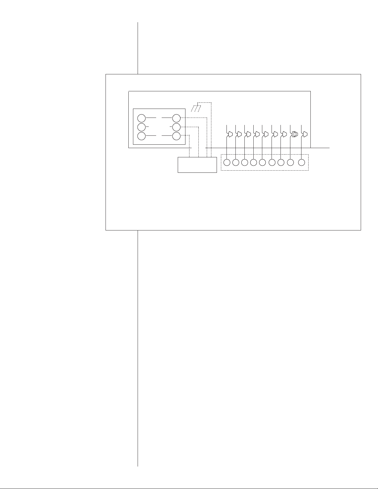
B. HOOK-UP
To wire unit, refer to the following hook-up diagram (see Figure 24).
Refer to Figure 4 for location of wiring entrances.
Wiring to be done in the field between the unit and devices not attached to the unit, or
between separate devices which are field installed and located, shall conform with the
temperature limitation for Type T wire [63°F rise (35°C)] when installed in accordance
with the manufacturer’s instructions.
FIGURE 24
WIRE HOOK-UP DIAGRAM
FOR INTERNAL WIRING SEE WIRING LABEL ATTACHED TO UNIT
CHASSIS GROUND
T1
CONTACTOR
T2
T3
(2
STAGE
ODD
GAS
HEAT
ONLY)
LOW VOLTAGE
WIRE LEADS
L1
*
L2
L3
Y GRWCY2 L
*L2 connection 3Phase only
HIGH VOLTAGE
DISCONNECT
SWITCH
YGRWC Y2 L
THERMOSTAT
Y - COOLING (LOW STAGE IN 2 STAGE SYSTEMS)
G - FAN ONLY
R - 24V
W - HEATING (LOW HEAT 2 STAGE GAS HEAT)
C - COMMON
Y2 - HIGH STAGE COOLING (TWO STAGE ONLY)
L - ALERT CODES (OPTIONAL WITH COMFORT ALERT
L - AND COMPATIBLE THERMOSTAT)
ODD - ON-DEMAND DEHUMIDIFICATION
W2 - HEATING (HIGH HEAT 2 STAGE GAS)
ODDW2W2
C. INTERNAL WIRING
IMPORTANT: Some single phase units are equipped with a single pole contactor.
Caution must be exercised when servicing as only one leg of the power supply is broken
with the contactor.
A diagram of the internal wiring of this unit is located under the electrical box cover and
in this manual. If any of the original wire as supplied with the appliance must be
replaced, the wire gauge and insulation must be same as original wiring.
Transformer is factory wired for 230 volts on 208/230 volt models and must be changed
for 208 volt applications. See unit wiring diagram for 208 volt wiring.
D. THERMOSTAT
The room thermostat must be compatible with the spark ignition control on the unit.
Generally, all thermostats that are not of the “current robbing” type are compatible with
the integrated furnace control. Two stage units (5 ton) require use of a thermostat capable of 2 stages of cooling. (See Section IV.) See chart below for recommendations. The
low voltage wiring should be sized as shown in Table 6.
Install the room thermostat in accordance with the instruction sheet packed in the box
with the thermostat. Never install the thermostat on an outside wall or where it will be
influenced by drafts, concealed hot or cold water pipes or ducts, lighting fixtures, radiation from fireplace, sun rays, lamps, televisions, radios or air streams from registers.
Refer to instructions packed with the thermostat for “heater” selection or adjustment.
Refer to the RRNL-/RRPL-/RRRL- Specification Sheets for a list of recommended thermostats.
27
Page 28
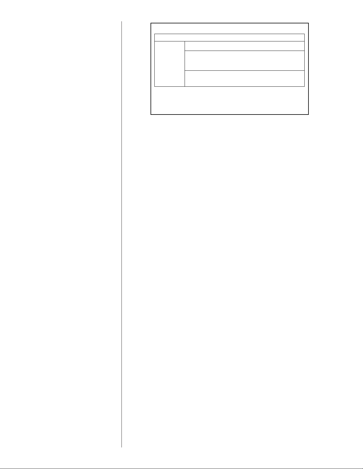
IX. FURNACE SECTION CONTROLS AND
FIELD WIRE SIZE FOR 24 VOLT THERMOSTAT CIRCUITS
SOLID COPPER WIRE - AWG.
3.0 16 14 12 10 10 10
2.5 16 14 12 12 12 10
2.0 18 16 14 12 12 10
50 100 150 200 250 300
Length of Run – Feet (1)
Thermostat Load - Amps
TABLE 6
(1) The total wire length is the distance from the furnace to the
thermostat and back to the furnace.
NOTE: DO NOT USE CONTROL WIRING SMALLER THAN NO. 18
AWG.
IGNITION SYSTEM
A. NORMAL FURNACE OPERATING SEQUENCE (SINGLE STAGE GAS HEAT)
This unit is equipped with an integrated direct spark ignition control.
1. The thermostat calls for heat.
2. The control board will run a self check to verify that the limit control and manual reset
overtemperature control are closed and that the pressure switch is open. If so, the
induced draft blower (inducer) begins a prepurge cycle.
3. The air proving negative pressure switch closes.
4. 15 seconds after the pressure switch closes, the gas valve opens and the spark is
initiated for a 7 second trial for ignition.
5. Burners ignite and flame sensor proves all burners have lit.
6. The circulating air blower is energized after 30 seconds.
7. The control board enters a normal operation loop in which all safety controls are monitored continuously.
8. Thermostat is satisfied and opens.
9. The gas valve is de-energized and closes, shutting down the burner flame.
10. The control board will de-energize the inducer after a five second post purge.
11. The circulating air blower is de-energized after 90 seconds.
• The integrated control board has a three ignition system.
• After a total of three trials for ignition without sensing main burner flame, the system
goes into a 100% lockout mode.
• After one hour, the ignition control repeats the prepurge and ignition cycles for 3 tries
and then goes into 100% lockout mode again.
• It continues this sequence of cycles and lockout each hour until ignition is successful or
power is interrupted.
• During the lockout mode, neither the spark ignition control or gas valve will be energized
until the system is reset by turning the thermostat to the “OFF” position or interrupting
the electrical power to the unit for 3 seconds or longer.
• The induced draft blower and main burner will shut off when the thermostat is satisfied.
• The circulating air blower will start and run on the heating speed if the thermostat fan
switch is in the “ON” position.
The integrated furnace control is equipped with diagnostic LED. The LED is lit continuously
when there is power to the control, with or without a call for heat. If the LED is not lit, there
is either no power to the control or there is an internal component failure within the control,
and the control should be replaced.
If the control detects the following failures, the LED will flash on for approximately 1/4 sec-
28
ond, then off for 3/4 second for designated failure detections.
1 Flash: Failed to detect flame within the three tries for ignition.
2 Flash: Pressure switch or induced draft blower problem detected.
3 Flash: High limit or auxiliary limit open.
4 Flash: Flame sensed and gas valve not energized or flame sensed with no “W” signal.
5 Flash: Overtemperature switch open.
B. NORMAL FURNACE OPERATING SEQUENCE (TWO STAGE GAS HEAT
FOR RRRL-C)
This unit is equipped with a two stage integrated direct spark ignition control.
TABLE 6
Page 29

NORMAL HEAT MODE
A. Call For First Stage (low fire) Only:
1. Zone thermostat contacts close, a call for first stage (low fire) heat is initiated.
2. Control runs self check.
3. Control checks the high-limit switch for normally closed contacts, each pressure switch
for normally open contacts, and all flame rollout switches for continuity.
4. Control energizes high inducer speed.
5. Control checks pressure switches for closure.
6. If pressure switches are closed, the control starts a 30 second prepurge.
7. After prepurge timeout, control initiates spark for 2 seconds minimum, 7 second maximum ignition trial, initiates 30 second, second stage (high fire) warm up timing.
8. Control detects flame, de-energizes spark and initiates 30 second delay on blower timing.
9. After a fixed 30 seconds indoor blower delay on, the control energizes the indoor blower.
10. After the 30 second second stage warmup period control checks thermostat input. If
only W1 is called for, W2 is de-energized and the control starts a 5 second off delay on
the W2 inducer speed.
11. After fixed 5 seconds the gas valve shifts to low and the W2 inducer speed is de-energized.
12. Control enters normal operating loop where all inputs are continuously checked.
B. Call For Second Stage, After First
Stage Established; Starting from A.11:
1. If a call for second stage (high fire) is initiated after a call for first stage heat is established, the control energizes the W2 inducer speed assures the high-fire pressure
switch is closed and energizes the second stage of the gas valve.
2. Control enters normal operating loop where all inputs are continuously checked.
C. Second Stage Satisfied; First Stage
Still Called For; Starting From B.2:
1. Once the call for second stage is satisfied, the control starts a 30 second off delay on
W2 inducer and reduces the gas valve to first stage.
2. Control enters normal operating loop where all inputs are continuously checked.
D. First Stage Satisfied:
1. Zone thermostat is satisfied.
2. Control de-energizes gas valve.
3. Control senses loss of flame.
4. Control initiates 5 second inducer postpurge and 90 second indoor blower delay off.
5. Control de-energizes inducer blower.
6. Control de-energizes indoor blower.
7. Control in the stand by mode with solid red LED.
E. First Stage and Second Stage
Removed Simultaneously:
1. Upon a loss of W1 and W2 the gas valve is de-energized.
2. Upon a loss of flame, the inducer will complete a 5 second postpurge and the indoor
blower will complete a 90 second delay off.
3. Control in the stand by mode with solid red LED.
The integrated control is a four-ignition system.
After a total of four cycles without sensing main burner flame, the system goes into a 100%
lockout mode. After one hour, the ignition control repeats the prepurge and ignition cycles
for 4 tries and then go into 100% lockout mode again. It continues this sequence of cycles
and lockout each hour until ignition is successful or power is interrupted. During the lockout
mode, neither the ignitor or gas valve will be energized until the system is reset by turning
the thermostat to the “OFF” position or interrupting the electrical power to the unit for 3
seconds or longer. The induced draft blower and main burner will shut off when the thermostat is satisfied.
The circulating air blower will start and run on the heating speed if the thermostat fan
switch is in the “ON” position.
The integrated furnace control is equipped with diagnostic LED. The LED is lit continuously
when there is power to the control, with or without a call for heat. If the LED is not lit, there
is either no power to the control or there is an internal component failure within the control,
and the control should be replaced.
If the control detects the following failures, the LED will flash on for approximately 1/4 second, then off for 3/4 second for designated failure detections.
1 Flash: Failed to detect flame within the four tries for ignition.
2 Flash: Pressure switch or induced draft blower problem detected.
3 Flash: High limit or auxiliary limit open.
4 Flash: Flame sensed and gas valve not energized or flame sensed with no “W” signal.
5 Flash: Overtemperature switch open.
29
Page 30
C. OPERATING INSTRUCTIONS
This appliance is equipped with a direct spark intermittent ignition device. This device
lights the main burners each time the room thermostat (closes) calls for heat. See operating instructions on the back of the furnace/controls access panel.
WARNING
!
DO NOT ATTEMPT TO MANUALLY LIGHT THIS FURNACE WITH A MATCH OR
ANY OPEN FLAME. ATTEMPTING TO DO SO CAN CAUSE AN EXPLOSION OR
FIRE RESULTING IN PROPERTY DAMAGE, PERSONAL INJURY OR DEATH.
TO START THE FURNACE
1. STOP! Read the safety information on the Operating Instructions Label located on this
appliance.
WARNING
!
IF YOU DO NOT FOLLOW THESE INSTRUCTIONS EXACTLY, A FIRE OR
EXPLOSION MAY RESULT CAUSING PROPERTY DAMAGE, PERSONAL
INJURY OR LOSS OF LIFE.
2. Set the thermostat to its lowest setting.
3. Turn off all electric power to the appliance.
4. This appliance does not have a pilot. It is equipped with an ignition device which automatically lights the burner. Do NOT
5. Remove control door/access panel.
6. Move switch to the “OFF” position.
7. Wait five (5) minutes to clear out any gas. Then smell for gas, including near the floor.
If you smell gas, STOP!
• Do not try to light any appliance.
• Do not touch any electric switch; do not use any phone in your building.
• Immediately call your gas supplier from a neighbor’s phone. Follow the gas supplier’s
• instructions.
• If you cannot reach your gas supplier, call the fire department.
If you don’t smell gas, go to the next step.
8. Move the switch from “OFF” position to “ON” position.
9. Replace the control door.
10. Turn on all electric power to the appliance.
11. Set the thermostat to the desired setting.
12. If the appliance will not operate, follow the instructions below on how to shut down the
furnace.
try to light the burner by hand.
30
WARNING
!
THE SPARK IGNITOR AND IGNITION LEAD FROM THE IGNITION CONTROL
ARE HIGH VOLTAGE. KEEP HANDS OR TOOLS AWAY TO PREVENT ELECTRICAL SHOCK. SHUT OFF ELECTRICAL POWER BEFORE SERVICING ANY
OF THE CONTROLS. FAILURE TO ADHERE TO THIS WARNING CAN RESULT
IN PERSONAL INJURY OR DEATH.
The initial start-up on a new installation may require the control system to be energized for
some time until any air has bled through the system and fuel gas is available at the burners.
TO SHUT DOWN FURNACE
1. Set the thermostat to the lowest setting.
2. Turn off all electric power to the appliance if service is to be performed.
3. Remove control door.
4. Move switch to the “OFF” position.
5. Replace control door.
Page 31

WARNING
!
SHOULD OVERHEATING OCCUR OR THE GAS SUPPLY FAIL TO SHUT OFF,
SHUT OFF THE MANUAL GAS VALVE TO THE APPLIANCE BEFORE SHUTTING OFF THE ELECTRICAL SUPPLY. FAILURE TO DO SO CAN RESULT IN
AN EXPLOSION OR FIRE CAUSING PROPERTY DAMAGE, SEVERE PERSONAL INJURY OR DEATH!
D. BURNERS
Burners for these units have been designed so that field adjustment is not required.
Burners are tray-mounted and accessible for easy cleaning when required.
E. MANUAL RESET OVERTEMPERATURE CONTROL
A manual reset overtemperature control is located on the burner shield. This device senses blockage in the heat exchanger or insufficient combustion air. This shuts off the main
burners if excessive temperatures occur in the burner compartment.
Operation of this control indicates an abnormal condition. Therefore, the unit should be
examined by a qualified installer, service agency, or the gas supplier before being placed
back into operation.
WARNING
!
DO NOT JUMPER THIS DEVICE! DO NOT reset the overtemperature control
without taking corrective action to assure that an adequate supply of combustion air is maintained under all conditions of operation. Failure to do so can
result in carbon monoxide poisoning or death. Replace this control only with
the identical replacement part.
F. PRESSURE SWITCH(S)
This furnace has pressure switches for sensing a blocked exhaust or a failed induced draft
blower. They’re normally open and close when the induced draft blower starts, indicating
air flow through the combustion chamber.
G. LIMIT CONTROL
The supply air high temperature limit cut-off is set at the factory and cannot be adjusted. It
is calibrated to prevent the air temperature leaving the furnace from exceeding the maximum outlet air temperature. WARNING: DO NOT JUMPER THIS DEVICE! Replace
this control only with the identical replacement part.
X. SYSTEM OPERATING INFORMATION
A. ADVISE THE CUSTOMER
1. Keep the air filters clean. The heating system operates better, more efficiently and
more economically.
2. Arrange the furniture and drapes so that the supply air registers and the return air
grilles are unobstructed.
3. Close doors and windows. This reduces the heating load on the system.
4. Avoid excessive use of exhaust fans.
5. Do not permit the heat generated by television, lamps or radios to influence the thermostat operation.
6. Except for the mounting platform, keep all combustible articles three feet from the unit
and exhaust system.
7. IMPORTANT: Replace all blower doors and compartment cover after servicing the
unit. Do not operate the unit without all panels and doors securely in place.
8. Do not allow snow or other debris to accumulate in the vicinity of the appliance.
B. FURNACE SECTION MAINTENANCE
The unit’s furnace should operate for many years without excessive scale build-up in flue
passageways; however, it is recommended that a qualified installer, service agency, or the
gas supplier annually inspect the flue passageways, the exhaust system and the burners
for continued safe operation, paying particular attention to deterioration from corrosion or
other sources.
If during inspection the flue passageways and exhaust system are determined to require
cleaning, the following procedures should be followed (by a qualified installer, service
agency, or gas supplier):
31
Page 32

1. Turn off the electrical power to the unit and set the thermostat to the lowest temperature.
2. Shut off the gas supply to the unit either at the meter or at manual valve in the
supply piping.
WARNING
!
LABEL ALL WIRES PRIOR TO DISCONNECTION WHEN SERVICING CONTROLS. WIRING ERRORS CAN CAUSE IMPROPER AND DANGEROUS OPERATION RESULTING IN FIRE, ELECTRICAL SHOCK, PROPERTY DAMAGE, PERSONAL INJURY OR DEATH.
3. Remove the furnace controls access panel and the control box cover.
4. Disconnect the gas supply piping from the gas valve.
5. Disconnect the wiring to the induced draft blower motor, gas valve, flame sensor, and
flame roll-out control, and ignitor cable. Mark all wires disconnected for proper
reconnection.
6. Remove the screws (4) connecting the burner tray to the heat exchanger mounting
panel.
7. Remove the burner tray and the manifold assembly from the unit.
8. Remove the screws (4) connecting the induced draft blower to the collector box and
screws (16) connecting the collector box to the heat exchanger mounting panel.
Remove the induced draft blower and the collector box from the unit.
9. Remove the turbulators from inside the heat exchangers by inserting the blade of a
screwdriver under the locking tabs. Pop the tabs out of the expanded grooves of the
heat exchanger. Slide the turbulators out of the heat exchangers.
10. Direct a water hose into the outlet of the heat exchanger top. Flush the inside of each
heat exchanger tube with water. Blow out each tube with air to remove excessive
moisture.
11. Reassemble (steps 1 through 10 in reverse order). Be careful not to strip out the
screw holes used to mount the collector box and inducer blower. Replace inducer blower gasket and collector box gasket with factory replacements if damaged.
WARNING
!
HOLES IN THE EXHAUST TRANSITION OR HEAT EXCHANGER CAN CAUSE
TOXIC FUMES TO ENTER THE HOME. THE EXHAUST TRANSITION OR HEAT
EXCHANGER MUST BE REPLACED IF THEY HAVE HOLES OR CRACKS IN
THEM. FAILURE TO DO SO CAN CAUSE CARBON MONOXIDE POISONING
RESULTING IN PERSONAL NJURY OR DEATH.
The manufacturer recommends that a qualified installer, service agency or the gas supplier visually inspect the burner flames for the desired flame appearance at the beginning of
the heating season and approximately midway in heating season.
The manufacturer also recommends that a qualified installer, service agency or the gas
supplier clean the flame sensor with steel wool at the beginning of the heating season.
WARNING
!
DISCONNECT MAIN ELECTRICAL POWER TO THE UNIT BEFORE ATTEMPTING MAINTENANCE. FAILURE TO DO SO MAY RESULT IN ELECTRICAL
SHOCK OR SEVERE PERSONAL INJURY OR DEATH.
C. LUBRICATION
IMPORTANT: DO NOT attempt to lubricate the bearings on the blower motor or the
induced draft blower motor. Addition of lubricants can reduce the motor life and void the
warranty.
The blower motor and induced draft blower motor are prelubricated by the manufacturer
and do not require further attention.
A qualified installer, service agency or the gas supplier must periodically clean the
motors to prevent the possibility of overheating due to an accumulation of dust and dirt
on the windings or on the motor exterior. And, as suggested elsewhere in these instructions, the air filters should be kept clean because dirty filters can restrict air flow and the
motor depends upon sufficient air flowing across and through it to prevent overheating.
32
Page 33

D. COOLING SECTION MAINTENANCE
WARNING
!
DISCONNECT MAIN ELECTRICAL POWER TO THE UNIT BEFORE ATTEMPTING MAINTENANCE. FAILURE TO DO SO MAY RESULT IN ELECTRICAL
SHOCK OR SEVERE PERSONAL INJURY OR DEATH.
It is recommended that at the beginning of each cooling season a qualified installer or
service agency inspect and clean the cooling section of this unit. The following areas
should be addressed: evaporator coil, condenser coil, condenser fan motor and venturi
area.
To inspect the evaporator coil:
1. Remove the filter access panel and the blower/evaporator coil access panel.
WARNING
!
LABEL ALL WIRES PRIOR TO DISCONNECTION WHEN SERVICING THE UNIT.
WIRING ERRORS CAN CAUSE IMPROPER AND DANGEROUS OPERATION
RESULTING IN FIRE, ELECTRICAL SHOCK, PROPERTY DAMAGE, SEVERE
PERSONAL INJURY OR DEATH.
2. Unplug the wires from the circulating air blower and the limit control. Remove the
two screws and slide the blower out of the unit sideways.
3. Shine a flashlight on the evaporator coil (both sides) and inspect for accumulation of
lint, insulation, etc.
4. If coil requires cleaning, follow the steps shown below.
Cleaning Evaporator Coil
1. Remove screws from condenser fan grille assembly and lay grille over on the unit
top panel.
2. Remove the controls access panel and the control box cover.
3. Disconnect the outdoor fan motor wiring from the compressor contactor and capacitor. Remove the strain relief in the bulkhead and pull the fan motor wires through.
Set grille assembly to the side.
4. Remove the screws that secure the unit top to the unit. Remove the top and set the
unit top to the side.
5. The coil should be cleaned when it is dry. If the coil is coated with dirt or lint, vacuum it with a soft brush attachment. Be careful not to bend the coil fins.
6. If the coil is coated with oil or grease, clean it with a mild detergent-and-water solution. Rinse the coil thoroughly with water. IMPORTANT: Do not
pressure. Excessive water pressure can bend the fins and tubing of the coil and lead
to inadequate unit performance. Be careful not to splash water excessively into unit.
7. Go to next section for cleaning the condenser coil.
Cleaning Condenser Coil, Drain Pan, Condensate Drain, Condenser Fan,
Circulation Air Blower and Venturi
1. Remove the screws from the condenser coil protective grille and remove the grille
from the unit. Ensure the filter access panel is still removed to access all of the
screws securing the grille.
2. The coil should be cleaned when it is dry. If the coil is coated with dirt or lint, vacuum
it with a soft brush attachment. Be careful not to bend the coil fins.
3. If the coil is coated with oil or grease, clean it with a mild detergent-and-water solution. Rinse the coil thoroughly with water. IMPORTANT: Do not
pressure. Excessive water pressure can bend the fins and tubing of the coil and lead
to inadequate unit performance. Be careful not to splash water excessively into unit.
4. Inspect the drain pan and condensate drain at the same time the condenser coil is
checked. Clean the drain pan by flushing with water and removing any matters of
obstructions which may be present.
5. Flush the drain tube with water. If the drain tube is blocked, it can usually be cleared
wth high pressure water.
6. Inspect the circulating air blower wheel and motor for accumulation of lint, dirt or
other obstruction and clean if necessary. Inspect the blower motor mounts and the
blower housing for loose mounts or other damage. Repair or replace if necessary.
use excessive water
use excessive water
Re-assembly
1. Place the condenser coil protective grille back on unit and replace all screws.
2. Place top panel back on unit and replace all screws.
3. Set condenser fan grille assembly on top of the unit with the fan on top and the
motor wires on the venturi side. Run the fan motor wires through the bulkhead and
33
Page 34

pull wires through the hole on the bottom of the control box on the left side and into
the control box. Reconnect fan motor wires per the wiring diagram attached to the
back of the control box cover.
4. Replace wire strain relief in bulkhead after the slack is pulled out of the wires on the
fan side. This will assure wires will not be damaged by the fan during unit operation.
5. Turn the condenser fan grille assembly over and into the recess in the unit top.
Secure the grille to the unit with the four screws removed earlier.
6. Replace the circulating air blower, making sure that all wires are properly reconnected per the unit wiring diagram.
7. Replace the filter and blower/evaporator coil access panels.
8. Replace the control box cover and controls access panel.
9. Restore electrical power to the unit and check for proper operation, especially the
condenser fan motor.
E. REPLACEMENT PARTS
Contact your local distributor for a complete parts list.
F. CHARGING
Refer to the appropriate charge chart included in this manual.
G. RRNL-/RRPL- BLOWER MOTOR SPEED ADJUSTMENTS
WARNING
!
DISCONNECT MAIN ELECTRICAL POWER TO THE UNIT BEFORE ATTEMPTING TO CHANGE BLOWER SPEEDS. FAILURE TO DO SO MAY RESULT IN
ELECTRICAL SHOCK OR SEVERE PERSONAL INJURY OR DEATH.
Note: These instructions to be used in conjunction with airflow data tables.
After determining necessary CFM and speed tap, follow the steps below to change
speeds.
Units with PSC Blower Motors:
1. Remove the furnace/control access panel.
2. Remove the control box cover. See Figure 25 for location of the furnace control
board.
3. Reference Figure 26 for the proper location of the wires on the speed tap block and
on the furnace control board to obtain the speed tap you have chosen.
Note: 460V units have dedicated heating and cooling speeds and should not be
adjusted.
4. After adjusting the wires accordingly, attach the control box cover, furnace control
access panel and the blower access panel to the unit.
Units with X-13 Motors
1. Remove blower access panel.
2. Locate wire terminals on the motor. Numbered terminals are 24V blower taps (See
airflow tables for corresponding speed). The C terminal is 24V common. L, N, and G
terminals are high voltage and must remain unchanged.
3. Cooling speeds can be adjusted as noted in Figure 26 by moving appropriate wire
between taps at the blower (Do not connect wires to unspecified speed taps).
Note: Heat speed is dedicated and should not be changed. The first stage cooling
speed on 5-ton models is dedicated and should not be changed.
4. Replace blower access panel.
34
Page 35

FIGURE 21
INTEGRATED FURNACE CONTROLBOARD
FIGURE 25
INTEGRATED FURNACE CONTROL BOARD
FIGURE 26
208/230 Volt PSC Motor
208/230 Volt X-13 Motor
2, 2.5, 3, 3.5, 4 TON MODELS
BL
COOL
R
HEAT
COOLING SPEED MAY BE ADJUSTED TO LOW
COOL BY MOVING BLUE WIRE TO TAP 2.
HEAT SPEED IS DEDICATED AND SHOULD
NOT BE ADJUSTED.
5 TON MODELS
Y/BL
2ND STAGE COOL
BL
1ST STAGE COOL
R
HEAT
SECOND STAGE COOLING SPEED MAY BE
ADJUSTED TO LOW COOL BY MOVING YELLOW
WITH BLUE STRIPE WIRE TO TAP 3. FIRST
STAGE COOLING SPEED IS DEDICATED AND
SHOULD NOT BE ADJUSTED. HEAT SPEED IS
DEDICATED AND SHOULD NOT BE ADJUSTED
NOTE: 460 Volt motors have dedicated speeds and are not adjustable.
35
Page 36

FIGURE 27
FACTORY SET BLOWER SPEEDS
MODEL
2.0 TON W/40K HEAT HIGH LOW HIGH (Tap 3) DEDICATED (Tap 1)
2.0 TON W/60K HEAT HIGH HEAT HIGH (Tap 3) DEDICATED (Tap 1)
2.0 TON W/80K HEAT HIGH HEAT HIGH (Tap 3) DEDICATED (Tap 1)
2.5 TON ALL HEAT INPUTS LOW LOW HIGH (Tap 3) DEDICATED (Tap 1)
3.0 TON ALL HEAT INPUTS MED LOW HIGH (Tap 3) DEDICATED (Tap 1)
3.5 TON ALL HEAT INPUTS HIGH LOW HIGH (Tap 3) DEDICATED (Tap 1)
4.0 TON ALL HEAT INPUTS HIGH LOW HIGH (Tap 3) DEDICATED (Tap 1)
*460 volt units: Do not adjust from factory speed.
PSC MOTOR
COOL HEAT COOL HEAT
1st Stage - DEDICATED (Tap 2)
2nd Stage - HIGH (Tap 4)
X-13 MOTOR
DEDICATED (Tap 1)5.0 TON ALL HEAT INPUTS N/A N/A
XI. UNITS WITH ECM BLOWER MOTORS
XI. (RRRL-C MODELS ONLY)
The ECM (Brushless permanent magnet) motor used on the blower in this product is programmed to operate over a wide range of external static pressures (0.0” - 1.0” W.C.) with
essentially constant air flow (CFM). Motor efficiency on ECM type motors is higher than that
of P.S.C. type motors normally used on this type product. See air flow performance data
tables.
The ECM motor is programmed to provide a “soft” start and stop. On a call for heat or cool,
the motor will gradually ramp up to the field selected CFM speed. This eliminates the sudden
rush of air and noise normally associated with a P.S.C. type motor. Once the thermostat and
blower delay are satisfied, the motor will gradually ramp down as well.
IMPORTANT: Units equipped with ECM motors cannot be used in by-pass zoning applications.
IMPORTANT: The A.C. power plug to the blower motor has locking tabs. It has been shown
that by applying excessive force to the A.C. cable half of the connector it is possible to force
the connector in backwards. It will not seat and “click” properly but will make connection. If
A.C. power is applied with the connector reversed the motor will be immediately destroyed. Do
not force power plug into motor connector backwards.
NOTE: Because of the harmonic content of the A.C. Line current to the ECM motor a conventional ammeter will not read correct motor amps. Only a true RMS meter will give accurate
AMP readings.
IMPORTANT: The flexibility of ECM motors and the fact that this flexibility is contained in programmed memory, not hardware, emphasizes the need for exact motor numbers for replacement motors. Because they all look the same, ECM MOTORS FROM DIFFERENT PRODUCTS OR DIFFERENT MODELS OF THE SAME PRODUCT MUST NOT
CHANGED.
IMPORTANT: If an ECM motor is replaced, it is important that the motor be mounted as the
original, as far into the blower wheel as practical for proper motor cooling.
IMPORTANT: The ECM motor is controlled directly from the room thermostat (in all modes
except heating). In cooling, the motor is controlled from the thermostat “Y” terminal. When the
“Y” or “R” thermostat circuit is opened a 30 second delay will occur before the blower motor
will cycle. In the heating mode the furnace control board controls the ECM through the blower
relay. When the “W” thermostat circuits are opened, a 90 second delay will occur before the
blower will cycle off. When the “G” to “R” thermostat circuit is opened for low speed blower,
there is no “off” delay. All thermostat sub-base combinations as recommended and provided
through the Parts Department have been tested and are compatible with the ECM motor used
in this equipment. Some thermostats may not be compatible with the ECM motor provided in
this unit. With thermostat in off state, the voltage on control lines “G”, “Y”, or W with respect to
24 vac common should be less than 3.5 VAC. If the measured voltage is too high, thermostat
is incompatible with the ECM motor and will cause the motor to run when it should be off.
BE INTER-
36
A. ECM MOTOR INTERFACE CONTROL AND SETTINGS
A. (RRRL UNITS ONLY)
The RRRL series units use ECM blower motors to deliver a constant level of airflow over a
wide range of external static pressures (up to 1.0" W.C.). The interface board provides the
required communications between the thermostat/IFC and the ECM blower motor. The interface board features:
• An automotive-style ATC blade fuse for transformer protection (3 amp).
Page 37

FIGURE 28
ECM INTERFACE BOARD
LED
FIRST-STAGE COOLING INPUT SECOND-STAGE COOLING INPUT
DO NOT WIRE DIRECTLY TO THIS BOARD. THERMOSTAT SHOULD
BE WIRED TO PIGTAILS LOCATED BELOW THE CONTROL BOX.
FIGURE 29
ECM MOTOR SETTINGS
(This board is located in the blower section)
(THIS BOARD IS LOCATED IN THE BLOWER SECTION)
• An on-board LED to indicate blower CFM.
• Inputs for two-stages of cooling: Y1 (first stage) and Y2 (second stage)
• Four (4) cooling delay profiles
The DIP switches on the interface board are used to define the operation of the ECM motor
(see Table 7).
TABLE 7
SWITCH FUNCTIONS
Switch Function
1 & 2 Not Used
3 & 4 Cooling Airflow Adjustment
5 & 6 Heating Airflow Settings
7 & 8 Cooling Delay Profiles
9 & 10 On-Demand Dehumidification
Refer to Figure 29 for switch identification and factory default settings.
IMPORTANT: Disconnect power to unit when changing DIP switch positions. Even if blower
is not operating, the motor will not recognize changes in DIP switch positions until unit power
is removed and then restored.
B. TRANSFORMER PROTECTION
The ECM interface board is equipped with an automotive-style 3 amp ATC blade fuse for
transformer protection. (See Figure 28.) If a short circuit occurs on the secondary side of the
transformer, the fuse will open.
C. USING THE ON-BOARD LED TO DETERMINE BLOWER CFM
The ECM interface board LED, which is located in the blower section (see Figure 28), indicates blower output by flashing one (1) second for every 100 CFM of airflow. The LED will
pause 1/10 second between each flash. After the blower CFM has been displayed, the LED
will illuminate dimly for 10 seconds before repeating the sequence. (See Table 8.)
NOTE: If airflow is not a multiple of 100 CFM, the last LED flash is a fraction of a second of
100 CFM.
37
Page 38

TABLE 8
LED FLASH CODES
Interface board
DIP switch
LED Output
settiings
1200 CFM
600 CFM
950 CFM
• Flashes 12 times
• Illuminate dimly 10 seconds, repeat sequence
• Flashes 6 times
• Illuminate dimly 10 seconds, repeat sequence
1
• Flashes 9 times, flash once for
/2 second
• Illuminate dimly 10 seconds, repeat sequence
D. UNIT OPERATION WITH TWO-STAGE COOLING
The RRRL unit provides distinct airflows for two-stage cooling. (See Figure 28.) Unit operation is defined as:
• Y1 – First Stage Cooling
• Y2 – Second Stage Cooling
A 24VAC signal provides input for the cooling stages.
NOTE: A 24VAC input to the Y2 terminal overrides the input to the Y1 terminal. (Both must be
energized to enable 2nd stage cooling.)
TABLE 9
TWO-STAGE OPERATION
Y1
INPUT
NONE
24 VAC
24 VAC
NONE
Y2
INPUT
NONE
NONE
24 VAC
24 VAC
COOLING
OPERATION
OFF
ST
1
STAGE
ND
2
STAGE
OFF
E. COOLING AIRFLOW ADJUSTMENTS
FIGURE 30
COOLING AIRFLOW ADJUSTMENTS
4
3
O
N
A
SELECTION SWITCH 3 SWITCH 4 AIRFLOW
4
3
O
N
4
3
O
N
4
3
O
N
BCD
POSITION POSITION ADJUSTMENT
A OFF OFF NONE
B ON OFF 10%
C OFF ON -10%
D ON ON NONE
COOLING
38
Cooling airflow may be adjusted +10% or –10% from nominal airflow using switches 3 & 4.
Refer to Figure 33 for switch positions to achieve the desired adjustments in airflow.
NOTE: Continuous fan speed is NOT affected by switches 3 & 4.
IMPORTANT: The use of On Demand Dehumidification overrides the cooling airflow adjust-
ments when high humidity is detected by a dehumidifying thermostat or humidistat when connected to the ODD terminal as shown in Figure 28. Refer to the Cooling Mode
Dehumidification section for more information.
Page 39

FIGURE 31
INTERFACE BOARD SWITCH
COOLING “ON” DELAY PROFILES
7 8 7 8 7 8 7 8
39
Page 40

FIGURE 32
INTERFACE BOARD SWITCH
BLOWER “OFF” DELAY PROFILES
40
7 8 7 8 7 8 7 8
Page 41

F. HEATING AIRFLOW ADJUSTMENTS
FIGURE 33
HEATING AIRFLOW ADJUSTMENTS
6
5
O
N
6
5
O
N
6
5
O
N
6
5
O
N
A
SELECTION SWITCH 5 SWITCH 6 AIRFLOW
BCD
HEATING
POSITION POSITION ADJUSTMENT
A OFF OFF NONE
B ON OFF 10%
C OFF ON -10%
D ON ON NONE
Heating airflow may be adjusted +10% or –10% from nominal airflow using switches 5 & 6.
Refer to Figure 33 for switch positions to achieve the desired adjustments in airflow.
NOTE: Continuous fan speed is NOT affected by switches 5 & 6.
G. COOLING DELAY PROFILES
The unit is shipped with a default ON/OFF delay profile for maximum efficiency. This default
may be overridden to maximize comfort by using one of the alternate profiles. ON delay profiles are shown in Figure 31.
OFF delay profiles are shown in Figure 32.
IMPORTANT: Blower ON delay profiles are not used in heating mode.
41
Page 42

H. COOLING MODE DEHUMIDIFICATION
An Explanation of On Demand Dehumidification Use
“On-Demand Dehumidification” (ODD) is an optional feature of the ECM interface board. The
ODD allows the user to have automatic dehumidification in the cooling mode that is controlled
by the user’s dehumidifying thermostat or humidistat setting. The humidistat should be wired
between the ODD (grey) pigtail and the R (red) pigtail. (Note: no field wiring should be connected directly to the ECM interface board.) When the humidity exceeds the humidistat setting, the airflow is decreased by a preprogrammed amount. This results in higher latent
capacity and increases the level of comfort.
Use of the ODD feature is important if maximum latent removal is desired. These systems
typically have a latent capacity between 24% to 28% of total system capacity. ODD drops
cooling airflow to boost latent capacity without significantly reducing total system capacity.
Refer to the thermostat wiring section of this manual for recommended dehumidifying thermostats.
IMPORTANT: Typical dehumidistats apply a 24V signal when humidity is high. This board
requires 24V when humidity is low. (See Table 10.)
I. ON DEMAND DEHUMIDIFICATION AIRFLOW ADJUSTMENT
Use switches 9 & 10 to lower cooling airflow as defined in the following table:
IMPORTANT: Selection A turns off the input of the ODD terminal. DO NOT USE SELECTION
A WITH A DEHUMIDIFYING THERMOSTAT OR HUMIDISTAT (refer to Figure 34).
TABLE 10
ODD TERMINAL
INDOOR INPUT TO “ODD”
AMBIENT TERMINAL
CONDITION (FROM HUMIDISTAT)
HIGH HUMIDITY Ø VAC
LOW HUMIDITY 24 VAC
FIGURE 34
10
9
O
N
A
SELECTION
A OFF OFF
B ON OFF
C OFF ON
D ON ON NONE
10
9
O
N
10
9
O
N
9
O
N
BCD
SWITCH 9 SWITCH 10
POSITION POSITION
10
COOLING AIRFLOW ADJUSTMENT
MAXIMUM LATENT REMOVAL
(WITHOUT ODD INPUT)
NONE
(FACTORY SETTING)
ON DEMAND DEHUMIDIFICATION
(WITH ODD INPUT)
EXPLANATION OF ABOVE SELECTIONS:
Selection A: Maximum Latent Removal
This selection lowers cooling airflow to maximize latent removal anytime there is a call for
cooling. This selection can be used in environments where there is always a high latent
load as in coastal and southern regions of the USA (see Table 11).
NOTE: Use of selection A in arid environments is not necessary and may cause unnecessary power consumption.
42
Page 43

TABLE 11
MODEL
RRRL-C024 OFF OFF 468 680
RRRL-C036 OFF OFF 680 1020
RRRL-C049 OFF OFF 893 1360
RRRL-C060 OFF OFF 1063 1573
SWITCH SWITCH Y1 Y2
9 POSITION 10 POSITION CFM CFM
Selection B: Factory Setting
This is the factory setting and provides cooling airflows as defined in the COOLING AIRFLOWS section (no reduction in airflow).
Selection C: On Demand Dehumidification
This selection allows On Demand Dehumidification when using a dehumidifying thermostat or humidistat connected to the ODD and “R” pigtails. Nominal airflow is reduced by a
preprogrammed amount to maximize latent removal. When high humidity is detected, the
cooling airflow as shown in Table 12.
TABLE 12
RRRL-
C024
C036
C049
C060 OFF ON
SWITCH 9
POSITION
OFF
OFF
OFF
SWITCH
10
POSITION
ON
ON
ON
ODD
INPUTY1CFMY2CFM
NONE
24VAC
NONE
24VAC
NONE
24VAC
NONE
24VAC
468
550
680
800
893
1050
1063
1250
680
800
1020
1200
1360
1600
1573
1850
IMPORTANT: A humidistat or dehumidifying thermostat MUST be connected to the “ODD”
and “R” pigtails when using this setting. Refer to the explanation of On Demand
Dehumidification use for more information.
Selection D: No Adjustment
This selection is the same as the factory setting and provides cooling airflows as defined in
the NOMINAL AIRFLOW ADJUSTMENT section.
ON DEMAND DEHUMIDIFICATION INTERACTIONS WITH AIRFLOW
ADJUSTMENT SETTINGS
On Demand Dehumidification switch settings (9 & 10) override the cooling airflow adjustment
switch settings (3 & 4). The +/-10% adjustments are turned OFF when Selection A (switch 9 &
10 are OFF) or Selection C (switch 9 OFF; switch 10 ON and no signal to ODD terminal) is
used.
43
Page 44

XII. GENERAL DATA - RRNL- MODELS
Model RRNL- Series B024JK04(E/X) B024JK06(E/X) B024JK08(E/X) B030JK04(E/X)
Cooling Performance
1
Continued ->
Gross Cooling Capacity Btu [kW] 24,400 [7.15] 24,400 [7.15] 24,400 [7.15] 29,800 [8.73]
EER/SEER
2
11.1/13 11.1/13 11.1/13 11.1/13
Nominal CFM/AHRI Rated CFM [L/s] 800/800 [378/378
]
800/800 [378/378
]
800/800 [378/378
]
1000/1000 [472/472
]
AHRI Net Cooling Capacity Btu [kW] 23,600 [6.91] 23,600 [6.91] 23,600 [6.91] 28,600 [8.38]
Net Sensible Capacity Btu [kW] 17,340 [5.08] 17,340 [5.08] 17,340 [5.08] 20,810 [6.1]
Net Latent Capacity Btu [kW] 6,260 [1.83] 6,260 [1.83] 6,260 [1.83] 7,790 [2.28]
Net System Power kW 2.12 2.12 2.12 2.58
Heating Performance (Gas)
4
Heating Input Btu [kW] 40,000 [11.72] 60,000 [17.58] 80,000 [23.44] 40,000 [11.72]
Heating Output Btu [kW] 31,000 [9.08] 47,000 [13.77] 62,000 [18.17] 31,000 [9.08]
Temperature Rise Range ºF [ºC] 30-60 [16.7-33.3] 40-70 [22.2-38.9] 55-85 [30.6-47.2] 20-50 [11.1-27.8]
AFUE % 80 80 80 80
Steady State Efficiency (%) 81 81 81 81
No. Burner
s
2342
No. Stages 1 1 1 1
Gas Connection Pipe Size in. [mm] 0.5 [12.7] 0.5 [12.7] 0.5 [12.7] 0.5 [12.7]
Compressor
No./Type 1/Scroll 1/Scroll 1/Scroll 1/Scroll
Outdoor Sound Rating (dB)
5
76 76 76 76
Outdoor Coil - Fin Type Louvered Louvered Louvered Louvered
Tube Type Rifled Rifled Rifled Rifled
Tube Size in. [mm] O
D
0.375 [9.5] 0.375 [9.5] 0.375 [9.5] 0.375 [9.5]
Face Area sq. ft. [sq. m] 10.56 [0.98] 10.56 [0.98] 10.56 [0.98] 10.56 [0.98]
Rows / FPI [FPcm] 1 / 18 [7] 1 / 18 [7] 1 / 18 [7] 1 / 18 [7]
Indoor Coil - Fin Type Louvered Louvered Louvered Louvered
Tube Type Rifled Rifled Rifled Rifled
Tube Size in. [mm] 0.375 [9.5] 0.375 [9.5] 0.375 [9.5] 0.375 [9.5]
Face Area sq. ft. [sq. m] 5.54 [0.51] 5.54 [0.51] 5.54 [0.51] 5.54 [0.51]
Rows / FPI [FPcm] 2 / 15 [6] 2 / 15 [6] 2 / 15 [6] 2 / 15 [6]
Refrigerant Control TX Valves TX Valves TX Valves TX Valves
Drain Connection No./Size in. [mm
]
1/0.75 [19.05] 1/0.75 [19.05] 1/0.75 [19.05] 1/0.75 [19.05]
Outdoor Fan - Type Propelle
r
Propelle
r
Propelle
r
Propelle
r
No. Used/Diameter in. [mm] 1/22 [558.8] 1/22 [558.8] 1/22 [558.8] 1/22 [558.8]
Drive Type/No. Speeds Direct/1 Direct/1 Direct/1 Direct/1
CFM [L/s] 2500 [1180] 2500 [1180] 2500 [1180] 2500 [1180]
No. Motors/HP 1 at 1/3 HP 1 at 1/3 HP 1 at 1/3 HP 1 at 1/3 HP
Motor RPM 1075 1075 1075 1075
Indoor Fan - Type FC Centrifugal FC Centrifugal FC Centrifugal FC Centrifugal
No. Used/Diameter in. [mm] 1/9x7 [229x178] 1/9x7 [229x178] 1/9x7 [229x178] 1/10x9 [254x229]
Drive Type/No. Speeds Direct/2 Direct/2 Direct/2 Direct/3
No. Motors 1 1 1 1
Motor HP 1/4 1/4 1/4 1/2
Motor RPM 1075 1075 1075 1075
Motor Frame Size 48 48 48 48
Filter - Type Field Supplied Field Supplied Field Supplied Field Supplied
Furnished No No No No
(NO.) Size Recommended in. [mm x mm x mm] (1)1x20x20 [25x508x508](1)1x20x20 [25x508x508](1)1x20x20 [25x508x508](1)1x24x24 [25x610x610
]
Refrigerant Charge Oz. [g] 77.8 [2206] 77.8 [2206] 77.8 [2206] 76.8 [2177]
Weights
Net Weight lbs. [kg] 381 [173] 385 [175] 390 [177] 399 [181]
Ship Weight lbs. [kg] 421 [191] 425 [193] 430 [195] 439 [199]
NOTES:
1. Cooling Performance is rated at 95°F ambient, 80°F entering dry bulb, 67°F entering wet bulb. Gross capacity does not include the effect of fan motor heat. ARI capacity is
net and includes the effect of fan motor heat. Units are suitable for operation to ±20% of nominal cfm. Units are certified in accordance with the Unitary Air Conditioner
Equipment certification program, which is based on ARI Standard 210/240 or 360.
2. EER and/or SEER are rated at ARI conditions and in accordance with DOE test procedures.
3. Heating Performance limit ettings and rating data were established and approved under laboratory test conditions using American National Standard Institute standards.
Ratings shown are for elevations up to 2000 feet. For elevations above 2000 feet, ratings should be reduced at the rate of 4% for each 1000 feet above sea level.
4. AFUE is rated in accordance with DOE test procedures.
5. Outdoor Sound Rating shown is tested in accordance with ARI Standard 270.
NOMINAL SIZES 2-5 TONS [7-15.8 kW]
44
Page 45

GENERAL DATA - RRNL- MODELS
Model RRNL- Series B030JK06(E/X) B030JK08(E/X) B030JK10(E/X) B036CK0
4
Cooling Performance
1
Continued ->
Gross Cooling Capacity Btu [kW] 29,800 [8.73] 29,800 [8.73] 29,800 [8.73] 37,000 [10.84]
EER/SEER
2
11.1/13 11.1/13 11.1/13 11.3/13
Nominal CFM/AHRI Rated CFM [L/s] 1000/1000 [472/472
]
1000/1000 [472/472
]
1000/1000 [472/472
]
1200/1200 [566/566
]
AHRI Net Cooling Capacity Btu [kW] 28,600 [8.38] 28,600 [8.38] 28,600 [8.38] 35,600 [10.43]
Net Sensible Capacity Btu [kW] 20,810 [6.1] 20,810 [6.1] 20,810 [6.1] 26,390 [7.73]
Net Latent Capacity Btu [kW] 7,790 [2.28] 7,790 [2.28] 7,790 [2.28] 9,210 [2.7]
Net System Power kW 2.58 2.58 2.58 3.15
Heating Performance (Gas)
4
Heating Input Btu [kW] 60,000 [17.58] 80,000 [23.44] 100,000 [29.3] 40,000 [11.72]
Heating Output Btu [kW] 47,000 [13.77] 62,000 [18.17] 77,000 [22.56] 32,400 [9.49]
Temperature Rise Range ºF [ºC] 30-60 [16.7-33.3] 40-70 [22.2-38.9] 45-85 [25-47.2] 20-50 [11.1-27.8]
AFUE % 80 80 80 80
Steady State Efficiency (%) 81 81 81 81
No. Burner
s
3452
No. Stages 1 1 1 1
Gas Connection Pipe Size in. [mm] 0.5 [12.7] 0.5 [12.7] 0.5 [12.7] 0.5 [12.7]
Compressor
No./Type 1/Scroll 1/Scroll 1/Scroll 1/Scroll
Outdoor Sound Rating (dB)
5
76 76 76 76
Outdoor Coil - Fin Type Louvered Louvered Louvered Louvered
Tube Type Rifled Rifled Rifled Rifled
Tube Size in. [mm] O
D
0.375 [9.5] 0.375 [9.5] 0.375 [9.5] 0.375 [9.5]
Face Area sq. ft. [sq. m] 10.56 [0.98] 10.56 [0.98] 10.56 [0.98] 14.8 [1.37]
Rows / FPI [FPcm] 1 / 18 [7] 1 / 18 [7] 1 / 18 [7] 1 / 22 [9]
Indoor Coil - Fin Type Louvered Louvered Louvered Louvered
Tube Type Rifled Rifled Rifled Rifled
Tube Size in. [mm] 0.375 [9.5] 0.375 [9.5] 0.375 [9.5] 0.375 [9.5]
Face Area sq. ft. [sq. m] 5.54 [0.51] 5.54 [0.51] 5.54 [0.51] 5.54 [0.51]
Rows / FPI [FPcm] 2 / 15 [6] 2 / 15 [6] 2 / 15 [6] 2 / 15 [6]
Refrigerant Control TX Valves TX Valves TX Valves TX Valves
Drain Connection No./Size in. [mm
]
1/0.75 [19.05] 1/0.75 [19.05] 1/0.75 [19.05] 1/0.75 [19.05]
Outdoor Fan - Type Propelle
r
Propelle
r
Propelle
r
Propelle
r
No. Used/Diameter in. [mm] 1/22 [558.8] 1/22 [558.8] 1/22 [558.8] 1/22 [558.8]
Drive Type/No. Speeds Direct/1 Direct/1 Direct/1 Direct/1
CFM [L/s] 2500 [1180] 2500 [1180] 2500 [1180] 2700 [1274]
No. Motors/HP 1 at 1/3 HP 1 at 1/3 HP 1 at 1/3 HP 1 at 1/3 HP
Motor RPM 1075 1075 1075 1075
Indoor Fan - Type FC Centrifugal FC Centrifugal FC Centrifugal FC Centrifugal
No. Used/Diameter in. [mm] 1/10x9 [254x229] 1/10x9 [254x229] 1/10x9 [254x229] 1/10x9 [254x229]
Drive Type/No. Speeds Direct/3 Direct/3 Direct/3 Direct/3
No. Motors 1 1 1 1
Motor HP 1/2 1/2 1/2 1/2
Motor RPM 1075 1075 1075 1075
Motor Frame Size 48 48 48 48
Filter - Type Field Supplied Field Supplied Field Supplied Field Supplied
Furnished No No No No
(NO.) Size Recommended in. [mm x mm x mm] (1)1x24x24 [25x610x610](1)1x24x24 [25x610x610](1)1x24x24 [25x610x610](1)1x24x24 [25x610x610
]
Refrigerant Charge Oz. [g] 76.8 [2177] 76.8 [2177] 76.8 [2177] 92.8 [2631]
Weights
Net Weight lbs. [kg] 404 [183] 409 [186] 414 [188] 412 [187]
Ship Weight lbs. [kg] 444 [201] 449 [204] 454 [206] 452 [205]
NOTES:
1. Cooling Performance is rated at 95°F ambient, 80°F entering dry bulb, 67°F entering wet bulb. Gross capacity does not include the effect of fan motor heat. ARI capacity is
net and includes the effect of fan motor heat. Units are suitable for operation to ±20% of nominal cfm. Units are certified in accordance with the Unitary Air Conditioner
Equipment certification program, which is based on ARI Standard 210/240 or 360.
2. EER and/or SEER are rated at ARI conditions and in accordance with DOE test procedures.
3. Heating Performance limit ettings and rating data were established and approved under laboratory test conditions using American National Standard Institute standards.
Ratings shown are for elevations up to 2000 feet. For elevations above 2000 feet, ratings should be reduced at the rate of 4% for each 1000 feet above sea level.
4. AFUE is rated in accordance with DOE test procedures.
5. Outdoor Sound Rating shown is tested in accordance with ARI Standard 270.
NOMINAL SIZES 2-5 TONS [7-15.8 kW]
45
Page 46

GENERAL DATA - RRNL- MODELS
Model RRNL- Series B036CK0
6
B036CK0
8
B036CK1
0
B036DK0
6
Cooling Performance
1
Continued ->
Gross Cooling Capacity Btu [kW] 37,000 [10.84] 37,000 [10.84] 37,000 [10.84] 37,000 [10.84]
EER/SEER
2
11.3/13 11.3/13 11.3/13 11.3/13
Nominal CFM/AHRI Rated CFM [L/s] 1200/1200 [566/566
]
1200/1200 [566/566
]
1200/1200 [566/566
]
1200/1200 [566/566
]
AHRI Net Cooling Capacity Btu [kW] 35,600 [10.43] 35,600 [10.43] 35,600 [10.43] 35,600 [10.43]
Net Sensible Capacity Btu [kW] 26,390 [7.73] 26,390 [7.73] 26,390 [7.73] 26,390 [7.73]
Net Latent Capacity Btu [kW] 9,210 [2.7] 9,210 [2.7] 9,210 [2.7] 9,210 [2.7]
Net System Power kW 3.15 3.15 3.15 3.15
Heating Performance (Gas)
4
Heating Input Btu [kW] 60,000 [17.58] 80,000 [23.44] 100,000 [29.3] 60,000 [17.58]
Heating Output Btu [kW] 48,600 [14.24] 64,800 [18.99] 81,000 [23.73] 48,600 [14.24]
Temperature Rise Range ºF [ºC] 30-60 [16.7-33.3] 40-70 [22.2-38.9] 45-85 [25-47.2] 30-60 [16.7-33.3]
AFUE % 80 80 80 80
Steady State Efficiency (%) 81 81 81 81
No. Burner
s
3453
No. Stages 1 1 1 1
Gas Connection Pipe Size in. [mm] 0.5 [12.7] 0.5 [12.7] 0.5 [12.7] 0.5 [12.7]
Compressor
No./Type 1/Scroll 1/Scroll 1/Scroll 1/Scroll
Outdoor Sound Rating (dB)
5
76 76 76 76
Outdoor Coil - Fin Type Louvered Louvered Louvered Louvered
Tube Type Rifled Rifled Rifled Rifled
Tube Size in. [mm] O
D
0.375 [9.5] 0.375 [9.5] 0.375 [9.5] 0.375 [9.5]
Face Area sq. ft. [sq. m] 14.8 [1.37] 14.8 [1.37] 14.8 [1.37] 14.8 [1.37]
Rows / FPI [FPcm] 1 / 22 [9] 1 / 22 [9] 1 / 22 [9] 1 / 22 [9]
Indoor Coil - Fin Type Louvered Louvered Louvered Louvered
Tube Type Rifled Rifled Rifled Rifled
Tube Size in. [mm] 0.375 [9.5] 0.375 [9.5] 0.375 [9.5] 0.375 [9.5]
Face Area sq. ft. [sq. m] 5.54 [0.51] 5.54 [0.51] 5.54 [0.51] 5.54 [0.51]
Rows / FPI [FPcm] 2 / 15 [6] 2 / 15 [6] 2 / 15 [6] 2 / 15 [6]
Refrigerant Control TX Valves TX Valves TX Valves TX Valves
Drain Connection No./Size in. [mm
]
1/0.75 [19.05] 1/0.75 [19.05] 1/0.75 [19.05] 1/0.75 [19.05]
Outdoor Fan - Type Propelle
r
Propelle
r
Propelle
r
Propelle
r
No. Used/Diameter in. [mm] 1/22 [558.8] 1/22 [558.8] 1/22 [558.8] 1/22 [558.8]
Drive Type/No. Speeds Direct/1 Direct/1 Direct/1 Direct/1
CFM [L/s] 2700 [1274] 2700 [1274] 2700 [1274] 2700 [1274]
No. Motors/HP 1 at 1/3 HP 1 at 1/3 HP 1 at 1/3 HP 1 at 1/3 HP
Motor RPM 1075 1075 1075 1075
Indoor Fan - Type FC Centrifugal FC Centrifugal FC Centrifugal FC Centrifugal
No. Used/Diameter in. [mm] 1/10x9 [254x229] 1/10x9 [254x229] 1/10x9 [254x229] 1/10x9 [254x229]
Drive Type/No. Speeds Direct/3 Direct/3 Direct/3 Direct/2
No. Motors 1 1 1 1
Motor HP 1/2 1/2 1/2 1/2
Motor RPM 1075 1075 1075 1075
Motor Frame Size 48 48 48 48
Filter - Type Field Supplied Field Supplied Field Supplied Field Supplied
Furnished No No No No
(NO.) Size Recommended in. [mm x mm x mm] (1)1x24x24 [25x610x610](1)1x24x24 [25x610x610](1)1x24x24 [25x610x610](1)1x24x24 [25x610x610
]
Refrigerant Charge Oz. [g] 92.8 [2631] 92.8 [2631] 92.8 [2631] 92.8 [2631]
Weights
Net Weight lbs. [kg] 417 [189] 422 [191] 426 [193] 417 [189]
Ship Weight lbs. [kg] 457 [207] 462 [210] 466 [211] 457 [207]
NOTES:
1. Cooling Performance is rated at 95°F ambient, 80°F entering dry bulb, 67°F entering wet bulb. Gross capacity does not include the effect of fan motor heat. ARI capacity is
net and includes the effect of fan motor heat. Units are suitable for operation to ±20% of nominal cfm. Units are certified in accordance with the Unitary Air Conditioner
Equipment certification program, which is based on ARI Standard 210/240 or 360.
2. EER and/or SEER are rated at ARI conditions and in accordance with DOE test procedures.
3. Heating Performance limit ettings and rating data were established and approved under laboratory test conditions using American National Standard Institute standards.
Ratings shown are for elevations up to 2000 feet. For elevations above 2000 feet, ratings should be reduced at the rate of 4% for each 1000 feet above sea level.
4. AFUE is rated in accordance with DOE test procedures.
5. Outdoor Sound Rating shown is tested in accordance with ARI Standard 270.
NOMINAL SIZES 2-5 TONS [7-15.8 kW]
46
Page 47

GENERAL DATA - RRNL- MODELS
Model RRNL- Series B036DK0
8
B036DK1
0
B036JK04(E/X) B036JK06(E/X)
Cooling Performance
1
Continued ->
Gross Cooling Capacity Btu [kW] 37,000 [10.84] 37,000 [10.84] 37,000 [10.84] 37,000 [10.84]
EER/SEER
2
11.3/13 11.3/13 11.3/13 11.3/13
Nominal CFM/AHRI Rated CFM [L/s] 1200/1200 [566/566
]
1200/1200 [566/566
]
1200/1200 [566/566
]
1200/1200 [566/566
]
AHRI Net Cooling Capacity Btu [kW] 35,600 [10.43] 35,600 [10.43] 35,600 [10.43] 35,600 [10.43]
Net Sensible Capacity Btu [kW] 26,390 [7.73] 26,390 [7.73] 26,390 [7.73] 26,390 [7.73]
Net Latent Capacity Btu [kW] 9,210 [2.7] 9,210 [2.7] 9,210 [2.7] 9,210 [2.7]
Net System Power kW 3.15 3.15 3.15 3.15
Heating Performance (Gas)
4
Heating Input Btu [kW] 80,000 [23.44] 100,000 [29.3] 40,000 [11.72] 60,000 [17.58]
Heating Output Btu [kW] 64,800 [18.99] 81,000 [23.73] 31,000 [9.08] 47,000 [13.77]
Temperature Rise Range ºF [ºC] 40-70 [22.2-38.9] 45-85 [25-47.2] 20-50 [11.1-27.8] 30-60 [16.7-33.3]
AFUE % 80 80 80 80
Steady State Efficiency (%) 81 81 81 81
No. Burner
s
4523
No. Stages 1 1 1 1
Gas Connection Pipe Size in. [mm] 0.5 [12.7] 0.5 [12.7] 0.5 [12.7] 0.5 [12.7]
Compressor
No./Type 1/Scroll 1/Scroll 1/Scroll 1/Scroll
Outdoor Sound Rating (dB)
5
76 76 76 76
Outdoor Coil - Fin Type Louvered Louvered Louvered Louvered
Tube Type Rifled Rifled Rifled Rifled
Tube Size in. [mm] O
D
0.375 [9.5] 0.375 [9.5] 0.375 [9.5] 0.375 [9.5]
Face Area sq. ft. [sq. m] 14.8 [1.37] 14.8 [1.37] 14.8 [1.37] 14.8 [1.37]
Rows / FPI [FPcm] 1 / 22 [9] 1 / 22 [9] 1 / 22 [9] 1 / 22 [9]
Indoor Coil - Fin Type Louvered Louvered Louvered Louvered
Tube Type Rifled Rifled Rifled Rifled
Tube Size in. [mm] 0.375 [9.5] 0.375 [9.5] 0.375 [9.5] 0.375 [9.5]
Face Area sq. ft. [sq. m] 5.54 [0.51] 5.54 [0.51] 5.54 [0.51] 5.54 [0.51]
Rows / FPI [FPcm] 2 / 15 [6] 2 / 15 [6] 2 / 15 [6] 2 / 15 [6]
Refrigerant Control TX Valves TX Valves TX Valves TX Valves
Drain Connection No./Size in. [mm
]
1/0.75 [19.05] 1/0.75 [19.05] 1/0.75 [19.05] 1/0.75 [19.05]
Outdoor Fan - Type Propelle
r
Propelle
r
Propelle
r
Propelle
r
No. Used/Diameter in. [mm] 1/22 [558.8] 1/22 [558.8] 1/22 [558.8] 1/22 [558.8]
Drive Type/No. Speeds Direct/1 Direct/1 Direct/1 Direct/1
CFM [L/s] 2700 [1274] 2700 [1274] 2700 [1274] 2700 [1274]
No. Motors/HP 1 at 1/3 HP 1 at 1/3 HP 1 at 1/3 HP 1 at 1/3 HP
Motor RPM 1075 1075 1075 1075
Indoor Fan - Type FC Centrifugal FC Centrifugal FC Centrifugal FC Centrifugal
No. Used/Diameter in. [mm] 1/10x9 [254x229] 1/10x9 [254x229] 1/10x9 [254x229] 1/10x9 [254x229]
Drive Type/No. Speeds Direct/2 Direct/2 Direct/3 Direct/3
No. Motors 1 1 1 1
Motor HP 1/2 1/2 1/2 1/2
Motor RPM 1075 1075 1075 1075
Motor Frame Size 48 48 48 48
Filter - Type Field Supplied Field Supplied Field Supplied Field Supplied
Furnished No No No No
(NO.) Size Recommended in. [mm x mm x mm] (1)1x24x24 [25x610x610](1)1x24x24 [25x610x610](1)1x24x24 [25x610x610](1)1x24x24 [25x610x610
]
Refrigerant Charge Oz. [g] 92.8 [2631] 92.8 [2631] 92.8 [2631] 92.8 [2631]
Weights
Net Weight lbs. [kg] 422 [191] 426 [193] 412 [187] 417 [189]
Ship Weight lbs. [kg] 462 [210] 466 [211] 452 [205] 457 [207]
NOTES:
1. Cooling Performance is rated at 95°F ambient, 80°F entering dry bulb, 67°F entering wet bulb. Gross capacity does not include the effect of fan motor heat. ARI capacity is
net and includes the effect of fan motor heat. Units are suitable for operation to ±20% of nominal cfm. Units are certified in accordance with the Unitary Air Conditioner
Equipment certification program, which is based on ARI Standard 210/240 or 360.
2. EER and/or SEER are rated at ARI conditions and in accordance with DOE test procedures.
3. Heating Performance limit ettings and rating data were established and approved under laboratory test conditions using American National Standard Institute standards.
Ratings shown are for elevations up to 2000 feet. For elevations above 2000 feet, ratings should be reduced at the rate of 4% for each 1000 feet above sea level.
4. AFUE is rated in accordance with DOE test procedures.
5. Outdoor Sound Rating shown is tested in accordance with ARI Standard 270.
NOMINAL SIZES 2-5 TONS [7-15.8 kW]
47
Page 48

Model RRNL- Series B036JK08(E/X) B036JK10(E/X) B042CK0
4
B042CK0
6
Cooling Performance
1
Continued ->
Gross Cooling Capacity Btu [kW] 37,000 [10.84] 37,000 [10.84] 44,000 [12.89] 44,000 [12.89]
EER/SEER
2
11.3/13 11.3/13 11.2/13 11.2/13
Nominal CFM/AHRI Rated CFM [L/s] 1200/1200 [566/566
]
1200/1200 [566/566
]
1400/1400 [661/661
]
1400/1400 [661/661
]
AHRI Net Cooling Capacity Btu [kW] 35,600 [10.43] 35,600 [10.43] 42,000 [12.31] 42,000 [12.31]
Net Sensible Capacity Btu [kW] 26,390 [7.73] 26,390 [7.73] 30,510 [8.94] 30,510 [8.94]
Net Latent Capacity Btu [kW] 9,210 [2.7] 9,210 [2.7] 11,490 [3.37] 11,490 [3.37]
Net System Power kW 3.15 3.15 3.73 3.73
Heating Performance (Gas)
4
Heating Input Btu [kW] 80,000 [23.44] 100,000 [29.3] 40,000 [11.72] 60,000 [17.58]
Heating Output Btu [kW] 62,000 [18.17] 77,000 [22.56] 32,400 [9.49] 48,600 [14.24]
Temperature Rise Range ºF [ºC] 40-70 [22.2-38.9] 45-85 [25-47.2] 20-50 [11.1-27.8] 30-60 [16.7-33.3]
AFUE % 80 80 80 80
Steady State Efficiency (%) 81 81 81 81
No. Burner
s
4523
No. Stages 1 1 1 1
Gas Connection Pipe Size in. [mm] 0.5 [12.7] 0.5 [12.7] 0.5 [12.7] 0.5 [12.7]
Compressor
No./Type 1/Scroll 1/Scroll 1/Scroll 1/Scroll
Outdoor Sound Rating (dB)
5
76 76 76 76
Outdoor Coil - Fin Type Louvered Louvered Louvered Louvered
Tube Type Rifled Rifled Rifled Rifled
Tube Size in. [mm] O
D
0.375 [9.5] 0.375 [9.5] 0.375 [9.5] 0.375 [9.5]
Face Area sq. ft. [sq. m] 14.8 [1.37] 14.8 [1.37] 16.65 [1.55] 16.65 [1.55]
Rows / FPI [FPcm] 1 / 22 [9] 1 / 22 [9] 1 / 22 [9] 1 / 22 [9]
Indoor Coil - Fin Type Louvered Louvered Louvered Louvered
Tube Type Rifled Rifled Rifled Rifled
Tube Size in. [mm] 0.375 [9.5] 0.375 [9.5] 0.375 [9.5] 0.375 [9.5]
Face Area sq. ft. [sq. m] 5.54 [0.51] 5.54 [0.51] 7.39 [0.69] 7.39 [0.69]
Rows / FPI [FPcm] 2 / 15 [6] 2 / 15 [6] 2 / 15 [6] 2 / 15 [6]
Refrigerant Control TX Valves TX Valves TX Valves TX Valves
Drain Connection No./Size in. [mm
]
1/0.75 [19.05] 1/0.75 [19.05] 1/0.75 [19.05] 1/0.75 [19.05]
Outdoor Fan - Type Propelle
r
Propelle
r
Propelle
r
Propelle
r
No. Used/Diameter in. [mm] 1/22 [558.8] 1/22 [558.8] 1/22 [558.8] 1/22 [558.8]
Drive Type/No. Speeds Direct/1 Direct/1 Direct/1 Direct/1
CFM [L/s] 2700 [1274] 2700 [1274] 3500 [1652] 3500 [1652]
No. Motors/HP 1 at 1/3 HP 1 at 1/3 HP 1 at 1/3 HP 1 at 1/3 HP
Motor RPM 1075 1075 1075 1075
Indoor Fan - Type FC Centrifugal FC Centrifugal FC Centrifugal FC Centrifugal
No. Used/Diameter in. [mm] 1/10x9 [254x229] 1/10x9 [254x229] 1/10x9 [254x229] 1/10x9 [254x229]
Drive Type/No. Speeds Direct/3 Direct/3 Direct/3 Direct/3
No. Motors 1 1 1 1
Motor HP 1/2 1/2 1/2 1/2
Motor RPM 1075 1075 1075 1075
Motor Frame Size 48 48 48 48
Filter - Type Field Supplied Field Supplied Field Supplied Field Supplied
Furnished No No No No
(NO.) Size Recommended in. [mm x mm x mm] (1)1x24x24 [25x610x610](1)1x24x24 [25x610x610](1)1x24x24 [25x610x610](1)1x24x24 [25x610x610
]
Refrigerant Charge Oz. [g] 92.8 [2631] 92.8 [2631] 112 [3175] 112 [3175]
Weights
Net Weight lbs. [kg] 422 [191] 426 [193] 422 [191] 427 [194]
Ship Weight lbs. [kg] 462 [210] 466 [211] 462 [210] 467 [212]
GENERAL DATA - RRNL- MODELS
NOTES:
1. Cooling Performance is rated at 95°F ambient, 80°F entering dry bulb, 67°F entering wet bulb. Gross capacity does not include the effect of fan motor heat. ARI capacity is
net and includes the effect of fan motor heat. Units are suitable for operation to ±20% of nominal cfm. Units are certified in accordance with the Unitary Air Conditioner
Equipment certification program, which is based on ARI Standard 210/240 or 360.
2. EER and/or SEER are rated at ARI conditions and in accordance with DOE test procedures.
3. Heating Performance limit ettings and rating data were established and approved under laboratory test conditions using American National Standard Institute standards.
Ratings shown are for elevations up to 2000 feet. For elevations above 2000 feet, ratings should be reduced at the rate of 4% for each 1000 feet above sea level.
4. AFUE is rated in accordance with DOE test procedures.
5. Outdoor Sound Rating shown is tested in accordance with ARI Standard 270.
NOMINAL SIZES 2-5 TONS [7-15.8 kW]
48
Page 49

GENERAL DATA - RRNL- MODELS
Model RRNL- Series B042CK0
8
B042CK1
0
B042JK04(E/X) B042JK06(E/X)
Cooling Performance
1
Continued ->
Gross Cooling Capacity Btu [kW] 44,000 [12.89] 44,000 [12.89] 44,000 [12.89] 44,000 [12.89]
EER/SEER
2
11.2/13 11.2/13 11.2/13 11.2/13
Nominal CFM/AHRI Rated CFM [L/s] 1400/1400 [661/661
]
1400/1400 [661/661
]
1400/1400 [661/661
]
1400/1400 [661/661
]
AHRI Net Cooling Capacity Btu [kW] 42,000 [12.31] 42,000 [12.31] 42,000 [12.31] 42,000 [12.31]
Net Sensible Capacity Btu [kW] 30,510 [8.94] 30,510 [8.94] 30,510 [8.94] 30,510 [8.94]
Net Latent Capacity Btu [kW] 11,490 [3.37] 11,490 [3.37] 11,490 [3.37] 11,490 [3.37]
Net System Power kW 3.73 3.73 3.73 3.73
Heating Performance (Gas)
4
Heating Input Btu [kW] 80,000 [23.44] 100,000 [29.3] 40,000 [11.72] 60,000 [17.58]
Heating Output Btu [kW] 64,800 [18.99] 81,000 [23.73] 31,000 [9.08] 47,000 [13.77]
Temperature Rise Range ºF [ºC] 40-70 [22.2-38.9] 45-85 [25-47.2] 20-50 [11.1-27.8] 30-60 [16.7-33.3]
AFUE % 80 80 80 80
Steady State Efficiency (%) 81 81 81 81
No. Burner
s
4523
No. Stages 1 1 1 1
Gas Connection Pipe Size in. [mm] 0.5 [12.7] 0.5 [12.7] 0.5 [12.7] 0.5 [12.7]
Compressor
No./Type 1/Scroll 1/Scroll 1/Scroll 1/Scroll
Outdoor Sound Rating (dB)
5
76 76 76 76
Outdoor Coil - Fin Type Louvered Louvered Louvered Louvered
Tube Type Rifled Rifled Rifled Rifled
Tube Size in. [mm] O
D
0.375 [9.5] 0.375 [9.5] 0.375 [9.5] 0.375 [9.5]
Face Area sq. ft. [sq. m] 16.65 [1.55] 16.65 [1.55] 16.65 [1.55] 16.65 [1.55]
Rows / FPI [FPcm] 1 / 22 [9] 1 / 22 [9] 1 / 22 [9] 1 / 22 [9]
Indoor Coil - Fin Type Louvered Louvered Louvered Louvered
Tube Type Rifled Rifled Rifled Rifled
Tube Size in. [mm] 0.375 [9.5] 0.375 [9.5] 0.375 [9.5] 0.375 [9.5]
Face Area sq. ft. [sq. m] 7.39 [0.69] 7.39 [0.69] 7.39 [0.69] 7.39 [0.69]
Rows / FPI [FPcm] 2 / 15 [6] 2 / 15 [6] 2 / 15 [6] 2 / 15 [6]
Refrigerant Control TX Valves TX Valves TX Valves TX Valves
Drain Connection No./Size in. [mm
]
1/0.75 [19.05] 1/0.75 [19.05] 1/0.75 [19.05] 1/0.75 [19.05]
Outdoor Fan - Type Propelle
r
Propelle
r
Propelle
r
Propelle
r
No. Used/Diameter in. [mm] 1/22 [558.8] 1/22 [558.8] 1/22 [558.8] 1/22 [558.8]
Drive Type/No. Speeds Direct/1 Direct/1 Direct/1 Direct/1
CFM [L/s] 3500 [1652] 3500 [1652] 3500 [1652] 3500 [1652]
No. Motors/HP 1 at 1/3 HP 1 at 1/3 HP 1 at 1/3 HP 1 at 1/3 HP
Motor RPM 1075 1075 1075 1075
Indoor Fan - Type FC Centrifugal FC Centrifugal FC Centrifugal FC Centrifugal
No. Used/Diameter in. [mm] 1/10x9 [254x229] 1/10x9 [254x229] 1/10x9 [254x229] 1/10x9 [254x229]
Drive Type/No. Speeds Direct/3 Direct/3 Direct/3 Direct/3
No. Motors 1 1 1 1
Motor HP 1/2 1/2 1/2 1/2
Motor RPM 1075 1075 1075 1075
Motor Frame Size 48 48 48 48
Filter - Type Field Supplied Field Supplied Field Supplied Field Supplied
Furnished No No No No
(NO.) Size Recommended in. [mm x mm x mm] (1)1x24x24 [25x610x610](1)1x24x24 [25x610x610](1)1x24x24 [25x610x610](1)1x24x24 [25x610x610
]
Refrigerant Charge Oz. [g] 112 [3175] 112 [3175] 112 [3175] 112 [3175]
Weights
Net Weight lbs. [kg] 432 [196] 437 [198] 422 [191] 427 [194]
Ship Weight lbs. [kg] 472 [214] 477 [216] 462 [210] 467 [212]
NOTES:
1. Cooling Performance is rated at 95°F ambient, 80°F entering dry bulb, 67°F entering wet bulb. Gross capacity does not include the effect of fan motor heat. ARI capacity is
net and includes the effect of fan motor heat. Units are suitable for operation to ±20% of nominal cfm. Units are certified in accordance with the Unitary Air Conditioner
Equipment certification program, which is based on ARI Standard 210/240 or 360.
2. EER and/or SEER are rated at ARI conditions and in accordance with DOE test procedures.
3. Heating Performance limit ettings and rating data were established and approved under laboratory test conditions using American National Standard Institute standards.
Ratings shown are for elevations up to 2000 feet. For elevations above 2000 feet, ratings should be reduced at the rate of 4% for each 1000 feet above sea level.
4. AFUE is rated in accordance with DOE test procedures.
5. Outdoor Sound Rating shown is tested in accordance with ARI Standard 270.
NOMINAL SIZES 2-5 TONS [7-15.8 kW]
49
Page 50

GENERAL DATA - RRNL- MODELS
Model RRNL- Series B042JK08(E/X) B042JK10(E/X) B048CK0
6
B048CK0
8
Cooling Performance
1
Continued ->
Gross Cooling Capacity Btu [kW] 44,000 [12.89] 44,000 [12.89] 50,000 [14.65] 50,000 [14.65]
EER/SEER
2
11.2/13 11.2/13 11.2/13 11.2/13
Nominal CFM/AHRI Rated CFM [L/s] 1400/1400 [661/661
]
1400/1400 [661/661
]
1600/1600 [755/755
]
1600/1600 [755/755
]
AHRI Net Cooling Capacity Btu [kW] 42,000 [12.31] 42,000 [12.31] 48,000 [14.06] 48,000 [14.06]
Net Sensible Capacity Btu [kW] 30,510 [8.94] 30,510 [8.94] 33,990 [9.96] 33,990 [9.96]
Net Latent Capacity Btu [kW] 11,490 [3.37] 11,490 [3.37] 14,010 [4.1] 14,010 [4.1]
Net System Power kW 3.73 3.73 4.28 4.28
Heating Performance (Gas)
4
Heating Input Btu [kW] 80,000 [23.44] 100,000 [29.3] 60,000 [17.58] 80,000 [23.44]
Heating Output Btu [kW] 62,000 [18.17] 77,000 [22.56] 48,600 [14.24] 64,800 [18.99]
Temperature Rise Range ºF [ºC] 40-70 [22.2-38.9] 45-85 [25-47.2] 30-60 [16.7-33.3] 40-70 [22.2-38.9]
AFUE % 80 80 80 80
Steady State Efficiency (%) 81 81 81 81
No. Burner
s
4534
No. Stages 1 1 1 1
Gas Connection Pipe Size in. [mm] 0.5 [12.7] 0.5 [12.7] 0.5 [12.7] 0.5 [12.7]
Compressor
No./Type 1/Scroll 1/Scroll 1/Scroll 1/Scroll
Outdoor Sound Rating (dB)
5
76 76 78 78
Outdoor Coil - Fin Type Louvered Louvered Louvered Louvered
Tube Type Rifled Rifled Rifled Rifled
Tube Size in. [mm] O
D
0.375 [9.5] 0.375 [9.5] 0.375 [9.5] 0.375 [9.5]
Face Area sq. ft. [sq. m] 16.65 [1.55] 16.65 [1.55] 16.23 [1.51] 16.23 [1.51]
Rows / FPI [FPcm] 1 / 22 [9] 1 / 22 [9] 2 / 22 [9] 2 / 22 [9]
Indoor Coil - Fin Type Louvered Louvered Louvered Louvered
Tube Type Rifled Rifled Rifled Rifled
Tube Size in. [mm] 0.375 [9.5] 0.375 [9.5] 0.375 [9.5] 0.375 [9.5]
Face Area sq. ft. [sq. m] 7.39 [0.69] 7.39 [0.69] 7.39 [0.69] 7.39 [0.69]
Rows / FPI [FPcm] 2 / 15 [6] 2 / 15 [6] 2 / 15 [6] 2 / 15 [6]
Refrigerant Control TX Valves TX Valves TX Valves TX Valves
Drain Connection No./Size in. [mm
]
1/0.75 [19.05] 1/0.75 [19.05] 1/0.75 [19.05] 1/0.75 [19.05]
Outdoor Fan - Type Propelle
r
Propelle
r
Propelle
r
Propelle
r
No. Used/Diameter in. [mm] 1/22 [558.8] 1/22 [558.8] 1/22 [558.8] 1/22 [558.8]
Drive Type/No. Speeds Direct/1 Direct/1 Direct/1 Direct/1
CFM [L/s] 3500 [1652] 3500 [1652] 3300 [1557] 3300 [1557]
No. Motors/HP 1 at 1/3 HP 1 at 1/3 HP 1 at 1/3 HP 1 at 1/3 HP
Motor RPM 1075 1075 1075 1075
Indoor Fan - Type FC Centrifugal FC Centrifugal FC Centrifugal FC Centrifugal
No. Used/Diameter in. [mm] 1/10x9 [254x229] 1/10x9 [254x229] 1/10x9 [254x229] 1/10x9 [254x229]
Drive Type/No. Speeds Direct/3 Direct/3 Direct/3 Direct/3
No. Motors 1 1 1 1
Motor HP 1/2 1/2 3/4 3/4
Motor RPM 1075 1075 1075 1075
Motor Frame Size 48 48 48 48
Filter - Type Field Supplied Field Supplied Field Supplied Field Supplied
Furnished No No No No
(NO.) Size Recommended in. [mm x mm x mm] (1)1x24x24 [25x610x610](1)1x24x24 [25x610x610](1)1x24x24 [25x610x610](1)1x24x24 [25x610x610
]
Refrigerant Charge Oz. [g] 112 [3175] 112 [3175] 161.2 [4570] 161.2 [4570]
Weights
Net Weight lbs. [kg] 432 [196] 437 [198] 452 [205] 457 [207]
Ship Weight lbs. [kg] 472 [214] 477 [216] 492 [223] 497 [225]
NOTES:
1. Cooling Performance is rated at 95°F ambient, 80°F entering dry bulb, 67°F entering wet bulb. Gross capacity does not include the effect of fan motor heat. ARI capacity is
net and includes the effect of fan motor heat. Units are suitable for operation to ±20% of nominal cfm. Units are certified in accordance with the Unitary Air Conditioner
Equipment certification program, which is based on ARI Standard 210/240 or 360.
2. EER and/or SEER are rated at ARI conditions and in accordance with DOE test procedures.
3. Heating Performance limit ettings and rating data were established and approved under laboratory test conditions using American National Standard Institute standards.
Ratings shown are for elevations up to 2000 feet. For elevations above 2000 feet, ratings should be reduced at the rate of 4% for each 1000 feet above sea level.
4. AFUE is rated in accordance with DOE test procedures.
5. Outdoor Sound Rating shown is tested in accordance with ARI Standard 270.
NOMINAL SIZES 2-5 TONS [7-15.8 kW]
50
Page 51

GENERAL DATA - RRNL- MODELS
Model RRNL- Series B048CK1
0
B048DK1
0
B048JK06(E/X) B048JK08(E/X)
Cooling Performance
1
Continued ->
Gross Cooling Capacity Btu [kW] 50,000 [14.65] 50,000 [14.65] 50,000 [14.65] 50,000 [14.65]
EER/SEER
2
11.2/13 11.2/13 11.2/13 11.2/13
Nominal CFM/AHRI Rated CFM [L/s] 1600/1600 [755/755
]
1600/1600 [755/755
]
1600/1600 [755/755
]
1600/1600 [755/755
]
AHRI Net Cooling Capacity Btu [kW] 48,000 [14.06] 48,000 [14.06] 48,000 [14.06] 48,000 [14.06]
Net Sensible Capacity Btu [kW] 33,990 [9.96] 33,990 [9.96] 33,990 [9.96] 33,990 [9.96]
Net Latent Capacity Btu [kW] 14,010 [4.1] 14,010 [4.1] 14,010 [4.1] 14,010 [4.1]
Net System Power kW 4.28 4.28 4.28 4.28
Heating Performance (Gas)
4
Heating Input Btu [kW] 100,000 [29.3] 100,000 [29.3] 60,000 [17.58] 80,000 [23.44]
Heating Output Btu [kW] 81,000 [23.73] 81,000 [23.73] 47,000 [13.77] 62,000 [18.17]
Temperature Rise Range ºF [ºC] 45-85 [25-47.2] 45-85 [25-47.2] 30-60 [16.7-33.3] 40-70 [22.2-38.9]
AFUE % 80 80 80 80
Steady State Efficiency (%) 81 81 81 81
No. Burner
s
5534
No. Stages 1 1 1 1
Gas Connection Pipe Size in. [mm] 0.5 [12.7] 0.5 [12.7] 0.5 [12.7] 0.5 [12.7]
Compressor
No./Type 1/Scroll 1/Scroll 1/Scroll 1/Scroll
Outdoor Sound Rating (dB)
5
78 78 78 78
Outdoor Coil - Fin Type Louvered Louvered Louvered Louvered
Tube Type Rifled Rifled Rifled Rifled
Tube Size in. [mm] O
D
0.375 [9.5] 0.375 [9.5] 0.375 [9.5] 0.375 [9.5]
Face Area sq. ft. [sq. m] 16.23 [1.51] 16.23 [1.51] 16.23 [1.51] 16.23 [1.51]
Rows / FPI [FPcm] 2 / 22 [9] 2 / 22 [9] 2 / 22 [9] 2 / 22 [9]
Indoor Coil - Fin Type Louvered Louvered Louvered Louvered
Tube Type Rifled Rifled Rifled Rifled
Tube Size in. [mm] 0.375 [9.5] 0.375 [9.5] 0.375 [9.5] 0.375 [9.5]
Face Area sq. ft. [sq. m] 7.39 [0.69] 7.39 [0.69] 7.39 [0.69] 7.39 [0.69]
Rows / FPI [FPcm] 2 / 15 [6] 2 / 15 [6] 2 / 15 [6] 2 / 15 [6]
Refrigerant Control TX Valves TX Valves TX Valves TX Valves
Drain Connection No./Size in. [mm
]
1/0.75 [19.05] 1/0.75 [19.05] 1/0.75 [19.05] 1/0.75 [19.05]
Outdoor Fan - Type Propelle
r
Propelle
r
Propelle
r
Propelle
r
No. Used/Diameter in. [mm] 1/22 [558.8] 1/22 [558.8] 1/22 [558.8] 1/22 [558.8]
Drive Type/No. Speeds Direct/1 Direct/1 Direct/1 Direct/1
CFM [L/s] 3300 [1557] 3300 [1557] 3300 [1557] 3300 [1557]
No. Motors/HP 1 at 1/3 HP 1 at 1/3 HP 1 at 1/3 HP 1 at 1/3 HP
Motor RPM 1075 1075 1075 1075
Indoor Fan - Type FC Centrifugal FC Centrifugal FC Centrifugal FC Centrifugal
No. Used/Diameter in. [mm] 1/10x9 [254x229] 1/10x9 [254x229] 1/10x9 [254x229] 1/10x9 [254x229]
Drive Type/No. Speeds Direct/3 Direct/2 Direct/3 Direct/3
No. Motors 1 1 1 1
Motor HP 3/4 3/4 3/4 3/4
Motor RPM 1075 1075 1075 1075
Motor Frame Size 48 48 48 48
Filter - Type Field Supplied Field Supplied Field Supplied Field Supplied
Furnished No No No No
(NO.) Size Recommended in. [mm x mm x mm] (1)1x24x24 [25x610x610](1)1x24x24 [25x610x610](1)1x24x24 [25x610x610](1)1x24x24 [25x610x610
]
Refrigerant Charge Oz. [g] 161.2 [4570] 161.2 [4570] 161.2 [4570] 161.2 [4570]
Weights
Net Weight lbs. [kg] 462 [210] 462 [210] 461 [209] 466 [211]
Ship Weight lbs. [kg] 502 [228] 502 [228] 501 [227] 506 [230]
NOTES:
1. Cooling Performance is rated at 95°F ambient, 80°F entering dry bulb, 67°F entering wet bulb. Gross capacity does not include the effect of fan motor heat. ARI capacity is
net and includes the effect of fan motor heat. Units are suitable for operation to ±20% of nominal cfm. Units are certified in accordance with the Unitary Air Conditioner
Equipment certification program, which is based on ARI Standard 210/240 or 360.
2. EER and/or SEER are rated at ARI conditions and in accordance with DOE test procedures.
3. Heating Performance limit ettings and rating data were established and approved under laboratory test conditions using American National Standard Institute standards.
Ratings shown are for elevations up to 2000 feet. For elevations above 2000 feet, ratings should be reduced at the rate of 4% for each 1000 feet above sea level.
4. AFUE is rated in accordance with DOE test procedures.
5. Outdoor Sound Rating shown is tested in accordance with ARI Standard 270.
NOMINAL SIZES 2-5 TONS [7-15.8 kW]
51
Page 52

GENERAL DATA - RRNL-B MODELS
NOTES:
1. Cooling Performance is rated at 95°F ambient, 80°F entering dry bulb, 67°F entering wet bulb. Gross capacity does not include the effect of fan motor heat. ARI capacity is
net and includes the effect of fan motor heat. Units are suitable for operation to ±20% of nominal cfm. Units are certified in accordance with the Unitary Air Conditioner
Equipment certification program, which is based on ARI Standard 210/240 or 360.
2. EER and/or SEER are rated at ARI conditions and in accordance with DOE test procedures.
3. Heating Performance limit ettings and rating data were established and approved under laboratory test conditions using American National Standard Institute standards.
Ratings shown are for elevations up to 2000 feet. For elevations above 2000 feet, ratings should be reduced at the rate of 4% for each 1000 feet above sea level.
4. AFUE is rated in accordance with DOE test procedures.
5. Outdoor Sound Rating shown is tested in accordance with ARI Standard 270.
Model RRNL- Series B048JK10(E/X) B060CK1
0
B060JK10(E/X) C060CK1
0
Cooling Performance
1
Continued ->
Gross Cooling Capacity Btu [kW] 50,000 [14.65] 59,500 [17.43] 59,500 [17.43] 59,500 [17.43]
EER/SEER
2
11.2/13 10.5/13 10.5/13 10.5/13
Nominal CFM/AHRI Rated CFM [L/s] 1600/1600 [755/755
]
2000/1850 [944/873
]
2000/1850 [944/873
]
2000/1850 [944/873
]
AHRI Net Cooling Capacity Btu [kW] 48,000 [14.06] 57,500 [16.85] 57,500 [16.85] 57,500 [16.85]
Net Sensible Capacity Btu [kW] 33,990 [9.96] 40,460 [11.85] 40,460 [11.85] 40,460 [11.85]
Net Latent Capacity Btu [kW] 14,010 [4.1] 17,040 [4.99] 17,040 [4.99] 17,040 [4.99]
Net System Power kW 4.28 5.48 5.48 5.48
Heating Performance (Gas)
4
Heating Input Btu [kW] 100,000 [29.3] 100,000 [29.3] 100,000 [29.3] 100,000 [29.3]
Heating Output Btu [kW] 77,000 [22.56] 81,000 [23.73] 77,000 [22.56] 81,000 [23.73]
Temperature Rise Range ºF [ºC] 45-85 [25-47.2] 45-85 [25-47.2] 45-85 [25-47.2] 45-85 [25-47.2]
AFUE % 80 80 80 80
Steady State Efficiency (%) 81 81 81 81
No. Burner
s
5555
No. Stages 1 1 1 1
Gas Connection Pipe Size in. [mm] 0.5 [12.7] 0.5 [12.7] 0.5 [12.7] 0.5 [12.7]
Compressor
No./Type 1/Scroll 1/Scroll 1/Scroll 1/Scroll
Outdoor Sound Rating (dB)
5
78 78 78 79
Outdoor Coil - Fin Type Louvered Louvered Louvered Louvered
Tube Type Rifled Rifled Rifled Rifled
Tube Size in. [mm] O
D
0.375 [9.5] 0.375 [9.5] 0.375 [9.5] 0.375 [9.5]
Face Area sq. ft. [sq. m] 16.23 [1.51] 16.23 [1.51] 16.23 [1.51] 16.23 [1.51]
Rows / FPI [FPcm] 2 / 22 [9] 2 / 22 [9] 2 / 22 [9] 2 / 22 [9]
Indoor Coil - Fin Type Louvered Louvered Louvered Louvered
Tube Type Rifled Rifled Rifled Rifled
Tube Size in. [mm] 0.375 [9.5] 0.375 [9.5] 0.375 [9.5] 0.375 [9.5]
Face Area sq. ft. [sq. m] 7.39 [0.69] 7.39 [0.69] 7.39 [0.69] 7.39 [0.69]
Rows / FPI [FPcm] 2 / 15 [6] 2 / 15 [6] 2 / 15 [6] 2 / 15 [6]
Refrigerant Control TX Valves TX Valves TX Valves TX Valves
Drain Connection No./Size in. [mm
]
1/0.75 [19.05] 1/0.75 [19.05] 1/0.75 [19.05] 1/0.75 [19.05]
Outdoor Fan - Type Propelle
r
Propelle
r
Propelle
r
Propelle
r
No. Used/Diameter in. [mm] 1/22 [558.8] 1/22 [558.8] 1/22 [558.8] 1/22 [558.8]
Drive Type/No. Speeds Direct/1 Direct/1 Direct/1 Direct/1
CFM [L/s] 3300 [1557] 3300 [1557] 3300 [1557] 3400 [1604]
No. Motors/HP 1 at 1/3 HP 1 at 1/3 HP 1 at 1/3 HP 1 at 1/3 HP
Motor RPM 1075 1075 1075 1075
Indoor Fan - Type FC Centrifugal FC Centrifugal FC Centrifugal FC Centrifugal
No. Used/Diameter in. [mm] 1/10x9 [254x229] 1/12x9 [305x229] 1/12x9 [305x229] 1/12x9 [305x229]
Drive Type/No. Speeds Direct/3 Direct/3 Direct/3 Direct/3
No. Motors 1 1 1 1
Motor HP 3/4 1 1 1
Motor RPM 1075 1075 1075 1075
Motor Frame Size 48 48 48 48
Filter - Type Field Supplied Field Supplied Field Supplied Field Supplied
Furnished No No No No
(NO.) Size Recommended in. [mm x mm x mm] (1)1x24x24 [25x610x610](1)1x24x30 [25x610x762](1)1x24x30 [25x610x762](1)1x24x30 [25x610x762
]
Refrigerant Charge Oz. [g] 161.2 [4570] 172.8 [4899] 172.8 [4899] 172.8 [4899]
Weights
Net Weight lbs. [kg] 471 [214] 532 [241] 532 [241] 564 [256]
Ship Weight lbs. [kg] 511 [232] 577 [262] 577 [262] 573 [260]
NOMINAL SIZES 2-5 TONS [7-15.8 kW]
52
Page 53

GENERAL DATA - RRNL-B MODELS
NOTES:
1. Cooling Performance is rated at 95°F ambient, 80°F entering dry bulb, 67°F entering wet bulb. Gross capacity does not include the effect of fan motor heat. ARI capacity is
net and includes the effect of fan motor heat. Units are suitable for operation to ±20% of nominal cfm. Units are certified in accordance with the Unitary Air Conditioner
Equipment certification program, which is based on ARI Standard 210/240 or 360.
2. EER and/or SEER are rated at ARI conditions and in accordance with DOE test procedures.
3. Heating Performance limit ettings and rating data were established and approved under laboratory test conditions using American National Standard Institute standards.
Ratings shown are for elevations up to 2000 feet. For elevations above 2000 feet, ratings should be reduced at the rate of 4% for each 1000 feet above sea level.
4. AFUE is rated in accordance with DOE test procedures.
5. Outdoor Sound Rating shown is tested in accordance with ARI Standard 270.
Model RRNL- Series C060DK1
0
C060JK10(E/X)
Cooling Performance
1
Gross Cooling Capacity Btu [kW] 59,500 [17.43] 59,500 [17.43]
EER/SEER
2
10.5/13 10.5/13
Nominal CFM/AHRI Rated CFM [L/s] 2000/1850 [944/873
]
2000/1850 [944/873
]
AHRI Net Cooling Capacity Btu [kW] 57,500 [16.85] 57,500 [16.85]
Net Sensible Capacity Btu [kW] 40,460 [11.85] 40,460 [11.85]
Net Latent Capacity Btu [kW] 17,040 [4.99] 17,040 [4.99]
Net System Power kW 5.48 5.48
Heating Performance (Gas)
4
Heating Input Btu [kW] 100,000 [29.3] 100,000 [29.3]
Heating Output Btu [kW] 81,000 [23.73] 77,000 [22.56]
Temperature Rise Range ºF [ºC] 45-85 [25-47.2] 45-85 [25-47.2]
AFUE % 80 80
Steady State Efficiency (%) 81 81
No. Burner
s
55
No. Stages 1 1
Gas Connection Pipe Size in. [mm] 0.5 [12.7] 0.5 [12.7]
Compressor
No./Type 1/Scroll 1/Scroll
Outdoor Sound Rating (dB)
5
79 79
Outdoor Coil - Fin Type Louvered Louvered
Tube Type Rifled Rifled
Tube Size in. [mm] O
D
0.375 [9.5] 0.375 [9.5]
Face Area sq. ft. [sq. m] 16.23 [1.51] 16.23 [1.51]
Rows / FPI [FPcm] 2 / 22 [9] 2 / 22 [9]
Indoor Coil - Fin Type Louvered Louvered
Tube Type Rifled Rifled
Tube Size in. [mm] 0.375 [9.5] 0.375 [9.5]
Face Area sq. ft. [sq. m] 7.39 [0.69] 7.39 [0.69]
Rows / FPI [FPcm] 2 / 15 [6] 2 / 15 [6]
Refrigerant Control TX Valves TX Valves
Drain Connection No./Size in. [mm
]
1/0.75 [19.05] 1/0.75 [19.05]
Outdoor Fan - Type Propelle
r
Propelle
r
No. Used/Diameter in. [mm] 1/22 [558.8] 1/22 [558.8]
Drive Type/No. Speeds Direct/1 Direct/1
CFM [L/s] 3400 [1604] 3400 [1604]
No. Motors/HP 1 at 1/3 HP 1 at 1/3 HP
Motor RPM 1075 1075
Indoor Fan - Type FC Centrifugal FC Centrifugal
No. Used/Diameter in. [mm] 1/12x9 [305x229] 1/12x9 [305x229]
Drive Type/No. Speeds Direct/3 Direct/3
No. Motors 1 1
Motor HP 1 1
Motor RPM 1075 1075
Motor Frame Size 48 48
Filter - Type Field Supplied Field Supplied
Furnished No No
(NO.) Size Recommended in. [mm x mm x mm] (1)1x24x30 [25x610x762](1)1x24x30 [25x610x762
]
Refrigerant Charge Oz. [g] 172.8 [4899] 172.8 [4899]
Weights
Net Weight lbs. [kg] 564 [256] 564 [256]
Ship Weight lbs. [kg] 573 [260] 573 [260]
NOMINAL SIZES 2-5 TONS [7-15.8 kW]
53
Page 54

GENERAL DATA - RRPL- MODELS
Model RRPL- Series B024JK04(E/X) B024JK06(E/X) B024JK08(E/X) B030JK04(E/X)
Cooling Performance
1
Continued ->
Gross Cooling Capacity Btu [kW] 24,400 [7.15] 24,400 [7.15] 24,400 [7.15] 29,600 [8.67]
EER/SEER
2
12/14 12/14 12/14 12/14
Nominal CFM/AHRI Rated CFM [L/s] 800/800 [378/378
]
800/800 [378/378
]
800/800 [378/378
]
1000/1000 [472/472
]
AHRI Net Cooling Capacity Btu [kW] 24,000 [7.03] 24,000 [7.03] 24,000 [7.03] 29,200 [8.56]
Net Sensible Capacity Btu [kW] 17,790 [5.21] 17,790 [5.21] 17,790 [5.21] 21,700 [6.36]
Net Latent Capacity Btu [kW] 6,210 [1.82] 6,210 [1.82] 6,210 [1.82] 7,500 [2.2]
Net System Power kW 2.01 2.01 2.01 2.43
Heating Performance (Gas)
4
Heating Input Btu [kW] 40,000 [11.72] 60,000 [17.58] 80,000 [23.44] 40,000 [11.72]
Heating Output Btu [kW] 31,000 [9.08] 47,000 [13.77] 62,000 [18.17] 31,000 [9.08]
Temperature Rise Range ºF [ºC] 30-60 [16.7-33.3] 40-70 [22.2-38.9] 55-85 [30.6-47.2] 20-50 [11.1-27.8]
AFUE % 80 80 80 80
Steady State Efficiency (%) 81 81 81 81
No. Burner
s
2342
No. Stages 1 1 1 1
Gas Connection Pipe Size in. [mm] 0.5 [12.7] 0.5 [12.7] 0.5 [12.7] 0.5 [12.7]
Compressor
No./Type 1/Scroll 1/Scroll 1/Scroll 1/Scroll
Outdoor Sound Rating (dB)
5
76 76 76 76
Outdoor Coil - Fin Type Louvered Louvered Louvered Louvered
Tube Type Rifled Rifled Rifled Rifled
Tube Size in. [mm] O
D
0.375 [9.5] 0.375 [9.5] 0.375 [9.5] 0.375 [9.5]
Face Area sq. ft. [sq. m] 10.56 [0.98] 10.56 [0.98] 10.56 [0.98] 10.56 [0.98]
Rows / FPI [FPcm] 1 / 18 [7] 1 / 18 [7] 1 / 18 [7] 1 / 18 [7]
Indoor Coil - Fin Type Louvered Louvered Louvered Louvered
Tube Type Rifled Rifled Rifled Rifled
Tube Size in. [mm] 0.375 [9.5] 0.375 [9.5] 0.375 [9.5] 0.375 [9.5]
Face Area sq. ft. [sq. m] 5.54 [0.51] 5.54 [0.51] 5.54 [0.51] 5.54 [0.51]
Rows / FPI [FPcm] 2 / 15 [6] 2 / 15 [6] 2 / 15 [6] 2 / 15 [6]
Refrigerant Control TX Valves TX Valves TX Valves TX Valves
Drain Connection No./Size in. [mm
]
1/0.75 [19.05] 1/0.75 [19.05] 1/0.75 [19.05] 1/0.75 [19.05]
Outdoor Fan - Type Propelle
r
Propelle
r
Propelle
r
Propelle
r
No. Used/Diameter in. [mm] 1/22 [558.8] 1/22 [558.8] 1/22 [558.8] 1/22 [558.8]
Drive Type/No. Speeds Direct/1 Direct/1 Direct/1 Direct/1
CFM [L/s] 2500 [1180] 2500 [1180] 2500 [1180] 2500 [1180]
No. Motors/HP 1 at 1/3 HP 1 at 1/3 HP 1 at 1/3 HP 1 at 1/3 HP
Motor RPM 1075 1075 1075 1075
Indoor Fan - Type FC Centrifugal FC Centrifugal FC Centrifugal FC Centrifugal
No. Used/Diameter in. [mm] 1/9x7 [229x178] 1/9x7 [229x178] 1/9x7 [229x178] 1/10x9 [254x229]
Drive Type/No. Speeds Direct/2 Direct/2 Direct/2 Direct/3
No. Motors 1 1 1 1
Motor HP 1/3 1/3 1/3 1/2
Motor RPM 1075 1075 1075 1075
Motor Frame Size 48 48 48 48
Filter - Type Field Supplied Field Supplied Field Supplied Field Supplied
Furnished No No No No
(NO.) Size Recommended in. [mm x mm x mm] (1)1x20x20 [25x508x508](1)1x20x20 [25x508x508](1)1x20x20 [25x508x508](1)1x24x24 [25x610x610
]
Refrigerant Charge Oz. [g] 77.8 [2206] 77.8 [2206] 77.8 [2206] 76.8 [2177]
Weights
Net Weight lbs. [kg] 381 [173] 385 [175] 390 [177] 399 [181]
Ship Weight lbs. [kg] 421 [191] 425 [193] 430 [195] 439 [199]
NOTES:
1. Cooling Performance is rated at 95°F ambient, 80°F entering dry bulb, 67°F entering wet bulb. Gross capacity does not include the effect of fan motor heat. ARI capacity is
net and includes the effect of fan motor heat. Units are suitable for operation to ±20% of nominal cfm. Units are certified in accordance with the Unitary Air Conditioner
Equipment certification program, which is based on ARI Standard 210/240 or 360.
2. EER and/or SEER are rated at ARI conditions and in accordance with DOE test procedures.
3. Heating Performance limit ettings and rating data were established and approved under laboratory test conditions using American National Standard Institute standards.
Ratings shown are for elevations up to 2000 feet. For elevations above 2000 feet, ratings should be reduced at the rate of 4% for each 1000 feet above sea level.
4. AFUE is rated in accordance with DOE test procedures.
5. Outdoor Sound Rating shown is tested in accordance with ARI Standard 270.
NOMINAL SIZES 2-5 TONS [7-15.8 kW]
54
Page 55

GENERAL DATA - RRPL- MODELS
Model RRPL- Series B030JK06(E/X) B030JK08(E/X) B030JK10(E/X) B036CK0
4
Cooling Performance
1
Continued ->
Gross Cooling Capacity Btu [kW] 29,600 [8.67] 29,600 [8.67] 29,600 [8.67] 36,800 [10.78]
EER/SEER
2
12/14 12/14 12/14 12/14
Nominal CFM/AHRI Rated CFM [L/s] 1000/1000 [472/472
]
1000/1000 [472/472
]
1000/1000 [472/472
]
1200/1200 [566/566
]
AHRI Net Cooling Capacity Btu [kW] 29,200 [8.56] 29,200 [8.56] 29,200 [8.56] 36,000 [10.55]
Net Sensible Capacity Btu [kW] 21,700 [6.36] 21,700 [6.36] 21,700 [6.36] 26,420 [7.74]
Net Latent Capacity Btu [kW] 7,500 [2.2] 7,500 [2.2] 7,500 [2.2] 9,580 [2.81]
Net System Power kW 2.43 2.43 2.43 2.94
Heating Performance (Gas)
4
Heating Input Btu [kW] 60,000 [17.58] 80,000 [23.44] 100,000 [29.3] 40,000 [11.72]
Heating Output Btu [kW] 47,000 [13.77] 62,000 [18.17] 77,000 [22.56] 32,400 [9.49]
Temperature Rise Range ºF [ºC] 30-60 [16.7-33.3] 40-70 [22.2-38.9] 45-85 [25-47.2] 20-50 [11.1-27.8]
AFUE % 80 80 80 80
Steady State Efficiency (%) 81 81 81 81
No. Burner
s
3452
No. Stages 1 1 1 1
Gas Connection Pipe Size in. [mm] 0.5 [12.7] 0.5 [12.7] 0.5 [12.7] 0.5 [12.7]
Compressor
No./Type 1/Scroll 1/Scroll 1/Scroll 1/Scroll
Outdoor Sound Rating (dB)
5
76 76 76 76
Outdoor Coil - Fin Type Louvered Louvered Louvered Louvered
Tube Type Rifled Rifled Rifled Rifled
Tube Size in. [mm] O
D
0.375 [9.5] 0.375 [9.5] 0.375 [9.5] 0.375 [9.5]
Face Area sq. ft. [sq. m] 10.56 [0.98] 10.56 [0.98] 10.56 [0.98] 14.8 [1.37]
Rows / FPI [FPcm] 1 / 18 [7] 1 / 18 [7] 1 / 18 [7] 1 / 22 [9]
Indoor Coil - Fin Type Louvered Louvered Louvered Louvered
Tube Type Rifled Rifled Rifled Rifled
Tube Size in. [mm] 0.375 [9.5] 0.375 [9.5] 0.375 [9.5] 0.375 [9.5]
Face Area sq. ft. [sq. m] 5.54 [0.51] 5.54 [0.51] 5.54 [0.51] 5.54 [0.51]
Rows / FPI [FPcm] 2 / 15 [6] 2 / 15 [6] 2 / 15 [6] 2 / 15 [6]
Refrigerant Control TX Valves TX Valves TX Valves TX Valves
Drain Connection No./Size in. [mm
]
1/0.75 [19.05] 1/0.75 [19.05] 1/0.75 [19.05] 1/0.75 [19.05]
Outdoor Fan - Type Propelle
r
Propelle
r
Propelle
r
Propelle
r
No. Used/Diameter in. [mm] 1/22 [558.8] 1/22 [558.8] 1/22 [558.8] 1/22 [558.8]
Drive Type/No. Speeds Direct/1 Direct/1 Direct/1 Direct/1
CFM [L/s] 2500 [1180] 2500 [1180] 2500 [1180] 2700 [1274]
No. Motors/HP 1 at 1/3 HP 1 at 1/3 HP 1 at 1/3 HP 1 at 1/3 HP
Motor RPM 1075 1075 1075 1075
Indoor Fan - Type FC Centrifugal FC Centrifugal FC Centrifugal FC Centrifugal
No. Used/Diameter in. [mm] 1/10x9 [254x229] 1/10x9 [254x229] 1/10x9 [254x229] 1/10x9 [254x229]
Drive Type/No. Speeds Direct/3 Direct/3 Direct/3 Direct/3
No. Motors 1 1 1 1
Motor HP 1/2 1/2 1/2 1/2
Motor RPM 1075 1075 1075 1075
Motor Frame Size 48 48 48 48
Filter - Type Field Supplied Field Supplied Field Supplied Field Supplied
Furnished No No No No
(NO.) Size Recommended in. [mm x mm x mm] (1)1x24x24 [25x610x610](1)1x24x24 [25x610x610](1)1x24x24 [25x610x610](1)1x24x24 [25x610x610
]
Refrigerant Charge Oz. [g] 76.8 [2177] 76.8 [2177] 76.8 [2177] 92.8 [2631]
Weights
Net Weight lbs. [kg] 404 [183] 409 [186] 414 [188] 412 [187]
Ship Weight lbs. [kg] 444 [201] 449 [204] 454 [206] 452 [205]
NOTES:
1. Cooling Performance is rated at 95°F ambient, 80°F entering dry bulb, 67°F entering wet bulb. Gross capacity does not include the effect of fan motor heat. ARI capacity is
net and includes the effect of fan motor heat. Units are suitable for operation to ±20% of nominal cfm. Units are certified in accordance with the Unitary Air Conditioner
Equipment certification program, which is based on ARI Standard 210/240 or 360.
2. EER and/or SEER are rated at ARI conditions and in accordance with DOE test procedures.
3. Heating Performance limit ettings and rating data were established and approved under laboratory test conditions using American National Standard Institute standards.
Ratings shown are for elevations up to 2000 feet. For elevations above 2000 feet, ratings should be reduced at the rate of 4% for each 1000 feet above sea level.
4. AFUE is rated in accordance with DOE test procedures.
5. Outdoor Sound Rating shown is tested in accordance with ARI Standard 270.
NOMINAL SIZES 2-5 TONS [7-15.8 kW]
55
Page 56

GENERAL DATA - RRPL- MODELS
NOTES:
1. Cooling Performance is rated at 95°F ambient, 80°F entering dry bulb, 67°F entering wet bulb. Gross capacity does not include the effect of fan motor heat. ARI capacity is
net and includes the effect of fan motor heat. Units are suitable for operation to ±20% of nominal cfm. Units are certified in accordance with the Unitary Air Conditioner
Equipment certification program, which is based on ARI Standard 210/240 or 360.
2. EER and/or SEER are rated at ARI conditions and in accordance with DOE test procedures.
3. Heating Performance limit ettings and rating data were established and approved under laboratory test conditions using American National Standard Institute standards.
Ratings shown are for elevations up to 2000 feet. For elevations above 2000 feet, ratings should be reduced at the rate of 4% for each 1000 feet above sea level.
4. AFUE is rated in accordance with DOE test procedures.
5. Outdoor Sound Rating shown is tested in accordance with ARI Standard 270.
Model RRPL- Series B036CK0
6
B036CK0
8
B036CK1
0
B036DK0
6
Cooling Performance
1
Continued ->
Gross Cooling Capacity Btu [kW] 36,800 [10.78] 36,800 [10.78] 36,800 [10.78] 36,800 [10.78]
EER/SEER
2
12/14 12/14 12/14 12/14
Nominal CFM/AHRI Rated CFM [L/s] 1200/1200 [566/566
]
1200/1200 [566/566
]
1200/1200 [566/566
]
1200/1200 [566/566
]
AHRI Net Cooling Capacity Btu [kW] 36,000 [10.55] 36,000 [10.55] 36,000 [10.55] 36,000 [10.55]
Net Sensible Capacity Btu [kW] 26,420 [7.74] 26,420 [7.74] 26,420 [7.74] 26,420 [7.74]
Net Latent Capacity Btu [kW] 9,580 [2.81] 9,580 [2.81] 9,580 [2.81] 9,580 [2.81]
Net System Power kW 2.94 2.94 2.94 2.94
Heating Performance (Gas)
4
Heating Input Btu [kW] 60,000 [17.58] 80,000 [23.44] 100,000 [29.3] 60,000 [17.58]
Heating Output Btu [kW] 48,600 [14.24] 64,800 [18.99] 81,000 [23.73] 48,600 [14.24]
Temperature Rise Range ºF [ºC] 30-60 [16.7-33.3] 40-70 [22.2-38.9] 45-85 [25-47.2] 30-60 [16.7-33.3]
AFUE % 80 80 80 80
Steady State Efficiency (%) 81 81 81 81
No. Burner
s
3453
No. Stages 1 1 1 1
Gas Connection Pipe Size in. [mm] 0.5 [12.7] 0.5 [12.7] 0.5 [12.7] 0.5 [12.7]
Compressor
No./Type 1/Scroll 1/Scroll 1/Scroll 1/Scroll
Outdoor Sound Rating (dB)
5
76 76 76 76
Outdoor Coil - Fin Type Louvered Louvered Louvered Louvered
Tube Type Rifled Rifled Rifled Rifled
Tube Size in. [mm] O
D
0.375 [9.5] 0.375 [9.5] 0.375 [9.5] 0.375 [9.5]
Face Area sq. ft. [sq. m] 14.8 [1.37] 14.8 [1.37] 14.8 [1.37] 14.8 [1.37]
Rows / FPI [FPcm] 1 / 22 [9] 1 / 22 [9] 1 / 22 [9] 1 / 22 [9]
Indoor Coil - Fin Type Louvered Louvered Louvered Louvered
Tube Type Rifled Rifled Rifled Rifled
Tube Size in. [mm] 0.375 [9.5] 0.375 [9.5] 0.375 [9.5] 0.375 [9.5]
Face Area sq. ft. [sq. m] 5.54 [0.51] 5.54 [0.51] 5.54 [0.51] 5.54 [0.51]
Rows / FPI [FPcm] 2 / 15 [6] 2 / 15 [6] 2 / 15 [6] 2 / 15 [6]
Refrigerant Control TX Valves TX Valves TX Valves TX Valves
Drain Connection No./Size in. [mm
]
1/0.75 [19.05] 1/0.75 [19.05] 1/0.75 [19.05] 1/0.75 [19.05]
Outdoor Fan - Type Propelle
r
Propelle
r
Propelle
r
Propelle
r
No. Used/Diameter in. [mm] 1/22 [558.8] 1/22 [558.8] 1/22 [558.8] 1/22 [558.8]
Drive Type/No. Speeds Direct/1 Direct/1 Direct/1 Direct/1
CFM [L/s] 2700 [1274] 2700 [1274] 2700 [1274] 2700 [1274]
No. Motors/HP 1 at 1/3 HP 1 at 1/3 HP 1 at 1/3 HP 1 at 1/3 HP
Motor RPM 1075 1075 1075 1075
Indoor Fan - Type FC Centrifugal FC Centrifugal FC Centrifugal FC Centrifugal
No. Used/Diameter in. [mm] 1/10x9 [254x229] 1/10x9 [254x229] 1/10x9 [254x229] 1/10x9 [254x229]
Drive Type/No. Speeds Direct/3 Direct/3 Direct/3 Direct/3
No. Motors 1 1 1 1
Motor HP 1/2 1/2 1/2 1/2
Motor RPM 1075 1075 1075 1075
Motor Frame Size 48 48 48 48
Filter - Type Field Supplied Field Supplied Field Supplied Field Supplied
Furnished No No No No
(NO.) Size Recommended in. [mm x mm x mm] (1)1x24x24 [25x610x610](1)1x24x24 [25x610x610](1)1x24x24 [25x610x610](1)1x24x24 [25x610x610
]
Refrigerant Charge Oz. [g] 92.8 [2631] 92.8 [2631] 92.8 [2631] 92.8 [2631]
Weights
Net Weight lbs. [kg] 417 [189] 422 [191] 426 [193] 417 [189]
Ship Weight lbs. [kg] 457 [207] 462 [210] 466 [211] 457 [207]
NOMINAL SIZES 2-5 TONS [7-15.8 kW]
56
Page 57

GENERAL DATA - RRPL- MODELS
NOTES:
1. Cooling Performance is rated at 95°F ambient, 80°F entering dry bulb, 67°F entering wet bulb. Gross capacity does not include the effect of fan motor heat. ARI capacity is
net and includes the effect of fan motor heat. Units are suitable for operation to ±20% of nominal cfm. Units are certified in accordance with the Unitary Air Conditioner
Equipment certification program, which is based on ARI Standard 210/240 or 360.
2. EER and/or SEER are rated at ARI conditions and in accordance with DOE test procedures.
3. Heating Performance limit ettings and rating data were established and approved under laboratory test conditions using American National Standard Institute standards.
Ratings shown are for elevations up to 2000 feet. For elevations above 2000 feet, ratings should be reduced at the rate of 4% for each 1000 feet above sea level.
4. AFUE is rated in accordance with DOE test procedures.
5. Outdoor Sound Rating shown is tested in accordance with ARI Standard 270.
Model RRPL- Series B036DK0
8
B036DK1
0
B036JK04(E/X) B036JK06(E/X)
Cooling Performance
1
Continued ->
Gross Cooling Capacity Btu [kW] 36,800 [10.78] 36,800 [10.78] 36,800 [10.78] 36,800 [10.78]
EER/SEER
2
12/14 12/14 12/14 12/14
Nominal CFM/AHRI Rated CFM [L/s] 1200/1200 [566/566
]
1200/1200 [566/566
]
1200/1200 [566/566
]
1200/1200 [566/566
]
AHRI Net Cooling Capacity Btu [kW] 36,000 [10.55] 36,000 [10.55] 36,000 [10.55] 36,000 [10.55]
Net Sensible Capacity Btu [kW] 26,420 [7.74] 26,420 [7.74] 26,420 [7.74] 26,420 [7.74]
Net Latent Capacity Btu [kW] 9,580 [2.81] 9,580 [2.81] 9,580 [2.81] 9,580 [2.81]
Net System Power kW 2.94 2.94 2.98 2.98
Heating Performance (Gas)
4
Heating Input Btu [kW] 80,000 [23.44] 100,000 [29.3] 40,000 [11.72] 60,000 [17.58]
Heating Output Btu [kW] 64,800 [18.99] 81,000 [23.73] 31,000 [9.08] 47,000 [13.77]
Temperature Rise Range ºF [ºC] 40-70 [22.2-38.9] 45-85 [25-47.2] 20-50 [11.1-27.8] 30-60 [16.7-33.3]
AFUE % 80 80 80 80
Steady State Efficiency (%) 81 81 81 81
No. Burner
s
4523
No. Stages 1 1 1 1
Gas Connection Pipe Size in. [mm] 0.5 [12.7] 0.5 [12.7] 0.5 [12.7] 0.5 [12.7]
Compressor
No./Type 1/Scroll 1/Scroll 1/Scroll 1/Scroll
Outdoor Sound Rating (dB)
5
76 76 76 76
Outdoor Coil - Fin Type Louvered Louvered Louvered Louvered
Tube Type Rifled Rifled Rifled Rifled
Tube Size in. [mm] O
D
0.375 [9.5] 0.375 [9.5] 0.375 [9.5] 0.375 [9.5]
Face Area sq. ft. [sq. m] 14.8 [1.37] 14.8 [1.37] 14.8 [1.37] 14.8 [1.37]
Rows / FPI [FPcm] 1 / 22 [9] 1 / 22 [9] 1 / 22 [9] 1 / 22 [9]
Indoor Coil - Fin Type Louvered Louvered Louvered Louvered
Tube Type Rifled Rifled Rifled Rifled
Tube Size in. [mm] 0.375 [9.5] 0.375 [9.5] 0.375 [9.5] 0.375 [9.5]
Face Area sq. ft. [sq. m] 5.54 [0.51] 5.54 [0.51] 5.54 [0.51] 5.54 [0.51]
Rows / FPI [FPcm] 2 / 15 [6] 2 / 15 [6] 2 / 15 [6] 2 / 15 [6]
Refrigerant Control TX Valves TX Valves TX Valves TX Valves
Drain Connection No./Size in. [mm
]
1/0.75 [19.05] 1/0.75 [19.05] 1/0.75 [19.05] 1/0.75 [19.05]
Outdoor Fan - Type Propelle
r
Propelle
r
Propelle
r
Propelle
r
No. Used/Diameter in. [mm] 1/22 [558.8] 1/22 [558.8] 1/22 [558.8] 1/22 [558.8]
Drive Type/No. Speeds Direct/1 Direct/1 Direct/1 Direct/1
CFM [L/s] 2700 [1274] 2700 [1274] 2700 [1274] 2700 [1274]
No. Motors/HP 1 at 1/3 HP 1 at 1/3 HP 1 at 1/3 HP 1 at 1/3 HP
Motor RPM 1075 1075 1075 1075
Indoor Fan - Type FC Centrifugal FC Centrifugal FC Centrifugal FC Centrifugal
No. Used/Diameter in. [mm] 1/10x9 [254x229] 1/10x9 [254x229] 1/10x9 [254x229] 1/10x9 [254x229]
Drive Type/No. Speeds Direct/3 Direct/3 Direct/3 Direct/3
No. Motors 1 1 1 1
Motor HP 1/2 1/2 1/2 1/2
Motor RPM 1075 1075 1075 1075
Motor Frame Size 48 48 48 48
Filter - Type Field Supplied Field Supplied Field Supplied Field Supplied
Furnished No No No No
(NO.) Size Recommended in. [mm x mm x mm] (1)1x24x24 [25x610x610](1)1x24x24 [25x610x610](1)1x24x24 [25x610x610](1)1x24x24 [25x610x610
]
Refrigerant Charge Oz. [g] 92.8 [2631] 92.8 [2631] 92.8 [2631] 92.8 [2631]
Weights
Net Weight lbs. [kg] 422 [191] 426 [193] 412 [187] 417 [189]
Ship Weight lbs. [kg] 462 [210] 466 [211] 452 [205] 457 [207]
NOMINAL SIZES 2-5 TONS [7-15.8 kW]
57
Page 58

GENERAL DATA - RRPL- MODELS
NOTES:
1. Cooling Performance is rated at 95°F ambient, 80°F entering dry bulb, 67°F entering wet bulb. Gross capacity does not include the effect of fan motor heat. ARI capacity is
net and includes the effect of fan motor heat. Units are suitable for operation to ±20% of nominal cfm. Units are certified in accordance with the Unitary Air Conditioner
Equipment certification program, which is based on ARI Standard 210/240 or 360.
2. EER and/or SEER are rated at ARI conditions and in accordance with DOE test procedures.
3. Heating Performance limit ettings and rating data were established and approved under laboratory test conditions using American National Standard Institute standards.
Ratings shown are for elevations up to 2000 feet. For elevations above 2000 feet, ratings should be reduced at the rate of 4% for each 1000 feet above sea level.
4. AFUE is rated in accordance with DOE test procedures.
5. Outdoor Sound Rating shown is tested in accordance with ARI Standard 270.
Model RRPL- Series B036JK08(E/X) B036JK10(E/X) B042CK0
4
B042CK0
6
Cooling Performance
1
Continued ->
Gross Cooling Capacity Btu [kW] 36,800 [10.78] 36,800 [10.78] 44,000 [12.89] 44,000 [12.89]
EER/SEER
2
12/14 12/14 12/14 12/14
Nominal CFM/AHRI Rated CFM [L/s] 1200/1200 [566/566
]
1200/1200 [566/566
]
1400/1400 [661/661
]
1400/1400 [661/661
]
AHRI Net Cooling Capacity Btu [kW] 36,000 [10.55] 36,000 [10.55] 43,000 [12.6] 43,000 [12.6]
Net Sensible Capacity Btu [kW] 26,420 [7.74] 26,420 [7.74] 31,270 [9.16] 31,270 [9.16]
Net Latent Capacity Btu [kW] 9,580 [2.81] 9,580 [2.81] 11,730 [3.44] 11,730 [3.44]
Net System Power kW 2.98 2.98 3.58 3.58
Heating Performance (Gas)
4
Heating Input Btu [kW] 80,000 [23.44] 100,000 [29.3] 40,000 [11.72] 60,000 [17.58]
Heating Output Btu [kW] 62,000 [18.17] 77,000 [22.56] 32,400 [9.49] 48,600 [14.24]
Temperature Rise Range ºF [ºC] 40-70 [22.2-38.9] 45-85 [25-47.2] 20-50 [11.1-27.8] 30-60 [16.7-33.3]
AFUE % 80 80 80 80
Steady State Efficiency (%) 81 81 81 81
No. Burner
s
4523
No. Stages 1 1 1 1
Gas Connection Pipe Size in. [mm] 0.5 [12.7] 0.5 [12.7] 0.5 [12.7] 0.5 [12.7]
Compressor
No./Type 1/Scroll 1/Scroll 1/Scroll 1/Scroll
Outdoor Sound Rating (dB)
5
76 76 76 76
Outdoor Coil - Fin Type Louvered Louvered Louvered Louvered
Tube Type Rifled Rifled Rifled Rifled
Tube Size in. [mm] O
D
0.375 [9.5] 0.375 [9.5] 0.375 [9.5] 0.375 [9.5]
Face Area sq. ft. [sq. m] 14.8 [1.37] 14.8 [1.37] 16.65 [1.55] 16.65 [1.55]
Rows / FPI [FPcm] 1 / 22 [9] 1 / 22 [9] 1 / 22 [9] 1 / 22 [9]
Indoor Coil - Fin Type Louvered Louvered Louvered Louvered
Tube Type Rifled Rifled Rifled Rifled
Tube Size in. [mm] 0.375 [9.5] 0.375 [9.5] 0.375 [9.5] 0.375 [9.5]
Face Area sq. ft. [sq. m] 5.54 [0.51] 5.54 [0.51] 7.39 [0.69] 7.39 [0.69]
Rows / FPI [FPcm] 2 / 15 [6] 2 / 15 [6] 2 / 15 [6] 2 / 15 [6]
Refrigerant Control TX Valves TX Valves TX Valves TX Valves
Drain Connection No./Size in. [mm
]
1/0.75 [19.05] 1/0.75 [19.05] 1/0.75 [19.05] 1/0.75 [19.05]
Outdoor Fan - Type Propelle
r
Propelle
r
Propelle
r
Propelle
r
No. Used/Diameter in. [mm] 1/22 [558.8] 1/22 [558.8] 1/22 [558.8] 1/22 [558.8]
Drive Type/No. Speeds Direct/1 Direct/1 Direct/1 Direct/1
CFM [L/s] 2700 [1274] 2700 [1274] 3500 [1652] 3500 [1652]
No. Motors/HP 1 at 1/3 HP 1 at 1/3 HP 1 at 1/3 HP 1 at 1/3 HP
Motor RPM 1075 1075 1075 1075
Indoor Fan - Type FC Centrifugal FC Centrifugal FC Centrifugal FC Centrifugal
No. Used/Diameter in. [mm] 1/10x9 [254x229] 1/10x9 [254x229] 1/10x9 [254x229] 1/10x9 [254x229]
Drive Type/No. Speeds Direct/3 Direct/3 Direct/3 Direct/3
No. Motors 1 1 1 1
Motor HP 1/2 1/2 1/2 1/2
Motor RPM 1075 1075 1075 1075
Motor Frame Size 48 48 48 48
Filter - Type Field Supplied Field Supplied Field Supplied Field Supplied
Furnished No No No No
(NO.) Size Recommended in. [mm x mm x mm] (1)1x24x24 [25x610x610](1)1x24x24 [25x610x610](1)1x24x24 [25x610x610](1)1x24x24 [25x610x610
]
Refrigerant Charge Oz. [g] 92.8 [2631] 92.8 [2631] 112 [3175] 112 [3175]
Weights
Net Weight lbs. [kg] 422 [191] 426 [193] 422 [191] 427 [194]
Ship Weight lbs. [kg] 462 [210] 466 [211] 462 [210] 467 [212]
NOMINAL SIZES 2-5 TONS [7-15.8 kW]
58
Page 59

GENERAL DATA - RRPL- MODELS
NOTES:
1. Cooling Performance is rated at 95°F ambient, 80°F entering dry bulb, 67°F entering wet bulb. Gross capacity does not include the effect of fan motor heat. ARI capacity is
net and includes the effect of fan motor heat. Units are suitable for operation to ±20% of nominal cfm. Units are certified in accordance with the Unitary Air Conditioner
Equipment certification program, which is based on ARI Standard 210/240 or 360.
2. EER and/or SEER are rated at ARI conditions and in accordance with DOE test procedures.
3. Heating Performance limit ettings and rating data were established and approved under laboratory test conditions using American National Standard Institute standards.
Ratings shown are for elevations up to 2000 feet. For elevations above 2000 feet, ratings should be reduced at the rate of 4% for each 1000 feet above sea level.
4. AFUE is rated in accordance with DOE test procedures.
5. Outdoor Sound Rating shown is tested in accordance with ARI Standard 270.
Model RRPL- Series B042CK0
8
B042CK1
0
B042JK04(E/X) B042JK06(E/X)
Cooling Performance
1
Continued ->
Gross Cooling Capacity Btu [kW] 44,000 [12.89] 44,000 [12.89] 44,000 [12.89] 44,000 [12.89]
EER/SEER
2
12/14 12/14 12/14 12/14
Nominal CFM/AHRI Rated CFM [L/s] 1400/1400 [661/661
]
1400/1400 [661/661
]
1400/1400 [661/661
]
1400/1400 [661/661
]
AHRI Net Cooling Capacity Btu [kW] 43,000 [12.6] 43,000 [12.6] 43,000 [12.6] 43,000 [12.6]
Net Sensible Capacity Btu [kW] 31,270 [9.16] 31,270 [9.16] 31,270 [9.16] 31,270 [9.16]
Net Latent Capacity Btu [kW] 11,730 [3.44] 11,730 [3.44] 11,730 [3.44] 11,730 [3.44]
Net System Power kW 3.58 3.58 3.58 3.58
Heating Performance (Gas)
4
Heating Input Btu [kW] 80,000 [23.44] 100,000 [29.3] 40,000 [11.72] 60,000 [17.58]
Heating Output Btu [kW] 64,800 [18.99] 81,000 [23.73] 31,000 [9.08] 47,000 [13.77]
Temperature Rise Range ºF [ºC] 40-70 [22.2-38.9] 45-85 [25-47.2] 20-50 [11.1-27.8] 30-60 [16.7-33.3]
AFUE % 80 80 80 80
Steady State Efficiency (%) 81 81 81 81
No. Burner
s
4523
No. Stages 1 1 1 1
Gas Connection Pipe Size in. [mm] 0.5 [12.7] 0.5 [12.7] 0.5 [12.7] 0.5 [12.7]
Compressor
No./Type 1/Scroll 1/Scroll 1/Scroll 1/Scroll
Outdoor Sound Rating (dB)
5
76 76 76 76
Outdoor Coil - Fin Type Louvered Louvered Louvered Louvered
Tube Type Rifled Rifled Rifled Rifled
Tube Size in. [mm] O
D
0.375 [9.5] 0.375 [9.5] 0.375 [9.5] 0.375 [9.5]
Face Area sq. ft. [sq. m] 16.65 [1.55] 16.65 [1.55] 16.65 [1.55] 16.65 [1.55]
Rows / FPI [FPcm] 1 / 22 [9] 1 / 22 [9] 1 / 22 [9] 1 / 22 [9]
Indoor Coil - Fin Type Louvered Louvered Louvered Louvered
Tube Type Rifled Rifled Rifled Rifled
Tube Size in. [mm] 0.375 [9.5] 0.375 [9.5] 0.375 [9.5] 0.375 [9.5]
Face Area sq. ft. [sq. m] 7.39 [0.69] 7.39 [0.69] 7.39 [0.69] 7.39 [0.69]
Rows / FPI [FPcm] 2 / 15 [6] 2 / 15 [6] 2 / 15 [6] 2 / 15 [6]
Refrigerant Control TX Valves TX Valves TX Valves TX Valves
Drain Connection No./Size in. [mm
]
1/0.75 [19.05] 1/0.75 [19.05] 1/0.75 [19.05] 1/0.75 [19.05]
Outdoor Fan - Type Propelle
r
Propelle
r
Propelle
r
Propelle
r
No. Used/Diameter in. [mm] 1/22 [558.8] 1/22 [558.8] 1/22 [558.8] 1/22 [558.8]
Drive Type/No. Speeds Direct/1 Direct/1 Direct/1 Direct/1
CFM [L/s] 3500 [1652] 3500 [1652] 3500 [1652] 3500 [1652]
No. Motors/HP 1 at 1/3 HP 1 at 1/3 HP 1 at 1/3 HP 1 at 1/3 HP
Motor RPM 1075 1075 1075 1075
Indoor Fan - Type FC Centrifugal FC Centrifugal FC Centrifugal FC Centrifugal
No. Used/Diameter in. [mm] 1/10x9 [254x229] 1/10x9 [254x229] 1/10x9 [254x229] 1/10x9 [254x229]
Drive Type/No. Speeds Direct/3 Direct/3 Direct/3 Direct/3
No. Motors 1 1 1 1
Motor HP 1/2 1/2 1/2 1/2
Motor RPM 1075 1075 1075 1075
Motor Frame Size 48 48 48 48
Filter - Type Field Supplied Field Supplied Field Supplied Field Supplied
Furnished No No No No
(NO.) Size Recommended in. [mm x mm x mm] (1)1x24x24 [25x610x610](1)1x24x24 [25x610x610](1)1x24x24 [25x610x610](1)1x24x24 [25x610x610
]
Refrigerant Charge Oz. [g] 112 [3175] 112 [3175] 112 [3175] 112 [3175]
Weights
Net Weight lbs. [kg] 432 [196] 437 [198] 422 [191] 427 [194]
Ship Weight lbs. [kg] 472 [214] 477 [216] 462 [210] 467 [212]
NOMINAL SIZES 2-5 TONS [7-15.8 kW]
59
Page 60

GENERAL DATA - RRPL- MODELS
NOTES:
1. Cooling Performance is rated at 95°F ambient, 80°F entering dry bulb, 67°F entering wet bulb. Gross capacity does not include the effect of fan motor heat. ARI capacity is
net and includes the effect of fan motor heat. Units are suitable for operation to ±20% of nominal cfm. Units are certified in accordance with the Unitary Air Conditioner
Equipment certification program, which is based on ARI Standard 210/240 or 360.
2. EER and/or SEER are rated at ARI conditions and in accordance with DOE test procedures.
3. Heating Performance limit ettings and rating data were established and approved under laboratory test conditions using American National Standard Institute standards.
Ratings shown are for elevations up to 2000 feet. For elevations above 2000 feet, ratings should be reduced at the rate of 4% for each 1000 feet above sea level.
4. AFUE is rated in accordance with DOE test procedures.
5. Outdoor Sound Rating shown is tested in accordance with ARI Standard 270.
Model RRPL- Series B042JK08(E/X) B042JK10(E/X) B048CK0
6
B048CK0
8
Cooling Performance
1
Continued ->
Gross Cooling Capacity Btu [kW] 44,000 [12.89] 44,000 [12.89] 50,500 [14.8] 50,500 [14.8]
EER/SEER
2
12/14 12/14 12/14 12/14
Nominal CFM/AHRI Rated CFM [L/s] 1400/1400 [661/661
]
1400/1400 [661/661
]
1600/1600 [755/755
]
1600/1600 [755/755
]
AHRI Net Cooling Capacity Btu [kW] 43,000 [12.6] 43,000 [12.6] 49,000 [14.36] 49,000 [14.36]
Net Sensible Capacity Btu [kW] 31,270 [9.16] 31,270 [9.16] 34,990 [10.25] 34,990 [10.25]
Net Latent Capacity Btu [kW] 11,730 [3.44] 11,730 [3.44] 14,010 [4.1] 14,010 [4.1]
Net System Power kW 3.58 3.58 4.04 4.04
Heating Performance (Gas)
4
Heating Input Btu [kW] 80,000 [23.44] 100,000 [29.3] 60,000 [17.58] 80,000 [23.44]
Heating Output Btu [kW] 62,000 [18.17] 77,000 [22.56] 48,600 [14.24] 64,800 [18.99]
Temperature Rise Range ºF [ºC] 40-70 [22.2-38.9] 45-85 [25-47.2] 30-60 [16.7-33.3] 40-70 [22.2-38.9]
AFUE % 80 80 80 80
Steady State Efficiency (%) 81 81 81 81
No. Burner
s
4534
No. Stages 1 1 1 1
Gas Connection Pipe Size in. [mm] 0.5 [12.7] 0.5 [12.7] 0.5 [12.7] 0.5 [12.7]
Compressor
No./Type 1/Scroll 1/Scroll 1/Scroll 1/Scroll
Outdoor Sound Rating (dB)
5
76 76 78 78
Outdoor Coil - Fin Type Louvered Louvered Louvered Louvered
Tube Type Rifled Rifled Rifled Rifled
Tube Size in. [mm] O
D
0.375 [9.5] 0.375 [9.5] 0.375 [9.5] 0.375 [9.5]
Face Area sq. ft. [sq. m] 16.65 [1.55] 16.65 [1.55] 16.23 [1.51] 16.23 [1.51]
Rows / FPI [FPcm] 1 / 22 [9] 1 / 22 [9] 2 / 22 [9] 2 / 22 [9]
Indoor Coil - Fin Type Louvered Louvered Louvered Louvered
Tube Type Rifled Rifled Rifled Rifled
Tube Size in. [mm] 0.375 [9.5] 0.375 [9.5] 0.375 [9.5] 0.375 [9.5]
Face Area sq. ft. [sq. m] 7.39 [0.69] 7.39 [0.69] 7.39 [0.69] 7.39 [0.69]
Rows / FPI [FPcm] 2 / 15 [6] 2 / 15 [6] 2 / 15 [6] 2 / 15 [6]
Refrigerant Control TX Valves TX Valves TX Valves TX Valves
Drain Connection No./Size in. [mm
]
1/0.75 [19.05] 1/0.75 [19.05] 1/0.75 [19.05] 1/0.75 [19.05]
Outdoor Fan - Type Propelle
r
Propelle
r
Propelle
r
Propelle
r
No. Used/Diameter in. [mm] 1/22 [558.8] 1/22 [558.8] 1/22 [558.8] 1/22 [558.8]
Drive Type/No. Speeds Direct/1 Direct/1 Direct/1 Direct/1
CFM [L/s] 3500 [1652] 3500 [1652] 3300 [1557] 3300 [1557]
No. Motors/HP 1 at 1/3 HP 1 at 1/3 HP 1 at 1/3 HP 1 at 1/3 HP
Motor RPM 1075 1075 1075 1075
Indoor Fan - Type FC Centrifugal FC Centrifugal FC Centrifugal FC Centrifugal
No. Used/Diameter in. [mm] 1/10x9 [254x229] 1/10x9 [254x229] 1/10x9 [254x229] 1/10x9 [254x229]
Drive Type/No. Speeds Direct/3 Direct/3 Direct/3 Direct/3
No. Motors 1 1 1 1
Motor HP 1/2 1/2 3/4 3/4
Motor RPM 1075 1075 1075 1075
Motor Frame Size 48 48 48 48
Filter - Type Field Supplied Field Supplied Field Supplied Field Supplied
Furnished No No No No
(NO.) Size Recommended in. [mm x mm x mm] (1)1x24x24 [25x610x610](1)1x24x24 [25x610x610](1)1x24x24 [25x610x610](1)1x24x24 [25x610x610
]
Refrigerant Charge Oz. [g] 112 [3175] 112 [3175] 161.2 [4570] 161.2 [4570]
Weights
Net Weight lbs. [kg] 432 [196] 437 [198] 452 [205] 457 [207]
Ship Weight lbs. [kg] 472 [214] 477 [216] 492 [223] 497 [225]
NOMINAL SIZES 2-5 TONS [7-15.8 kW]
60
Page 61

GENERAL DATA - RRPL- MODELS
NOTES:
1. Cooling Performance is rated at 95°F ambient, 80°F entering dry bulb, 67°F entering wet bulb. Gross capacity does not include the effect of fan motor heat. ARI capacity is
net and includes the effect of fan motor heat. Units are suitable for operation to ±20% of nominal cfm. Units are certified in accordance with the Unitary Air Conditioner
Equipment certification program, which is based on ARI Standard 210/240 or 360.
2. EER and/or SEER are rated at ARI conditions and in accordance with DOE test procedures.
3. Heating Performance limit ettings and rating data were established and approved under laboratory test conditions using American National Standard Institute standards.
Ratings shown are for elevations up to 2000 feet. For elevations above 2000 feet, ratings should be reduced at the rate of 4% for each 1000 feet above sea level.
4. AFUE is rated in accordance with DOE test procedures.
5. Outdoor Sound Rating shown is tested in accordance with ARI Standard 270.
Model RRPL- Series B048CK1
0
B048DK1
0
B048JK06(E/X) B048JK08(E/X)
Cooling Performance
1
Continued ->
Gross Cooling Capacity Btu [kW] 50,500 [14.8] 50,500 [14.8] 50,500 [14.8] 50,500 [14.8]
EER/SEER
2
12/14 12/14 12/14 12/14
Nominal CFM/AHRI Rated CFM [L/s] 1600/1600 [755/755
]
1600/1600 [755/755
]
1600/1600 [755/755
]
1600/1600 [755/755
]
AHRI Net Cooling Capacity Btu [kW] 49,000 [14.36] 49,000 [14.36] 49,000 [14.36] 49,000 [14.36]
Net Sensible Capacity Btu [kW] 34,990 [10.25] 34,990 [10.25] 34,990 [10.25] 34,990 [10.25]
Net Latent Capacity Btu [kW] 14,010 [4.1] 14,010 [4.1] 14,010 [4.1] 14,010 [4.1]
Net System Power kW 4.04 4.04 4.04 4.04
Heating Performance (Gas)
4
Heating Input Btu [kW] 100,000 [29.3] 100,000 [29.3] 60,000 [17.58] 80,000 [23.44]
Heating Output Btu [kW] 81,000 [23.73] 81,000 [23.73] 47,000 [13.77] 62,000 [18.17]
Temperature Rise Range ºF [ºC] 45-85 [25-47.2] 45-85 [25-47.2] 30-60 [16.7-33.3] 40-70 [22.2-38.9]
AFUE % 80 80 80 80
Steady State Efficiency (%) 81 81 81 81
No. Burner
s
5534
No. Stages 1 1 1 1
Gas Connection Pipe Size in. [mm] 0.5 [12.7] 0.5 [12.7] 0.5 [12.7] 0.5 [12.7]
Compressor
No./Type 1/Scroll 1/Scroll 1/Scroll 1/Scroll
Outdoor Sound Rating (dB)
5
78 78 78 78
Outdoor Coil - Fin Type Louvered Louvered Louvered Louvered
Tube Type Rifled Rifled Rifled Rifled
Tube Size in. [mm] O
D
0.375 [9.5] 0.375 [9.5] 0.375 [9.5] 0.375 [9.5]
Face Area sq. ft. [sq. m] 16.23 [1.51] 16.23 [1.51] 16.23 [1.51] 16.23 [1.51]
Rows / FPI [FPcm] 2 / 22 [9] 2 / 22 [9] 2 / 22 [9] 2 / 22 [9]
Indoor Coil - Fin Type Louvered Louvered Louvered Louvered
Tube Type Rifled Rifled Rifled Rifled
Tube Size in. [mm] 0.375 [9.5] 0.375 [9.5] 0.375 [9.5] 0.375 [9.5]
Face Area sq. ft. [sq. m] 7.39 [0.69] 7.39 [0.69] 7.39 [0.69] 7.39 [0.69]
Rows / FPI [FPcm] 2 / 15 [6] 2 / 15 [6] 2 / 15 [6] 2 / 15 [6]
Refrigerant Control TX Valves TX Valves TX Valves TX Valves
Drain Connection No./Size in. [mm
]
1/0.75 [19.05] 1/0.75 [19.05] 1/0.75 [19.05] 1/0.75 [19.05]
Outdoor Fan - Type Propelle
r
Propelle
r
Propelle
r
Propelle
r
No. Used/Diameter in. [mm] 1/22 [558.8] 1/22 [558.8] 1/22 [558.8] 1/22 [558.8]
Drive Type/No. Speeds Direct/1 Direct/1 Direct/1 Direct/1
CFM [L/s] 3300 [1557] 3300 [1557] 3300 [1557] 3300 [1557]
No. Motors/HP 1 at 1/3 HP 1 at 1/3 HP 1 at 1/3 HP 1 at 1/3 HP
Motor RPM 1075 1075 1075 1075
Indoor Fan - Type FC Centrifugal FC Centrifugal FC Centrifugal FC Centrifugal
No. Used/Diameter in. [mm] 1/10x9 [254x229] 1/10x9 [254x229] 1/10x9 [254x229] 1/10x9 [254x229]
Drive Type/No. Speeds Direct/3 Direct/3 Direct/3 Direct/3
No. Motors 1 1 1 1
Motor HP 3/4 3/4 3/4 3/4
Motor RPM 1075 1075 1075 1075
Motor Frame Size 48 48 48 48
Filter - Type Field Supplied Field Supplied Field Supplied Field Supplied
Furnished No No No No
(NO.) Size Recommended in. [mm x mm x mm] (1)1x24x24 [25x610x610](1)1x24x24 [25x610x610](1)1x24x24 [25x610x610](1)1x24x24 [25x610x610
]
Refrigerant Charge Oz. [g] 161.2 [4570] 161.2 [4570] 161.2 [4570] 161.2 [4570]
Weights
Net Weight lbs. [kg] 462 [210] 462 [210] 461 [209] 466 [211]
Ship Weight lbs. [kg] 502 [228] 502 [228] 501 [227] 506 [230]
NOMINAL SIZES 2-5 TONS [7-15.8 kW]
61
Page 62

GENERAL DATA - RRPL- MODELS
NOTES:
1. Cooling Performance is rated at 95°F ambient, 80°F entering dry bulb, 67°F entering wet bulb. Gross capacity does not include the effect of fan motor heat. ARI capacity is
net and includes the effect of fan motor heat. Units are suitable for operation to ±20% of nominal cfm. Units are certified in accordance with the Unitary Air Conditioner
Equipment certification program, which is based on ARI Standard 210/240 or 360.
2. EER and/or SEER are rated at ARI conditions and in accordance with DOE test procedures.
3. Heating Performance limit ettings and rating data were established and approved under laboratory test conditions using American National Standard Institute standards.
Ratings shown are for elevations up to 2000 feet. For elevations above 2000 feet, ratings should be reduced at the rate of 4% for each 1000 feet above sea level.
4. AFUE is rated in accordance with DOE test procedures.
5. Outdoor Sound Rating shown is tested in accordance with ARI Standard 270.
Model RRPL- Series B048JK10(E/X) B060CK1
0
B060DK1
0
B060JK10(E/X)
Cooling Performance
1
Gross Cooling Capacity Btu [kW] 50,500 [14.8] 59,500 [17.43] 59,500 [17.43] 59,500 [17.43]
EER/SEER
2
12/14 10.8/14 10.8/14 10.8/14
Nominal CFM/AHRI Rated CFM [L/s] 1600/1600 [755/755
]
2000/1850 [944/873
]
2000/1850 [944/873
]
2000/1850 [944/873
]
AHRI Net Cooling Capacity Btu [kW] 49,000 [14.36] 57,500 [16.85] 57,500 [16.85] 57,500 [16.85]
Net Sensible Capacity Btu [kW] 34,990 [10.25] 40,460 [11.85] 40,460 [11.85] 40,460 [11.85]
Net Latent Capacity Btu [kW] 14,010 [4.1] 17,040 [4.99] 17,040 [4.99] 17,040 [4.99]
Net System Power kW 4.04 5.32 5.32 5.32
Heating Performance (Gas)
4
Heating Input Btu [kW] 100,000 [29.3] 100,000 [29.3] 100,000 [29.3] 100,000 [29.3]
Heating Output Btu [kW] 77,000 [22.56] 81,000 [23.73] 81,000 [23.73] 77,000 [22.56]
Temperature Rise Range ºF [ºC] 45-85 [25-47.2] 45-85 [25-47.2] 45-85 [25-47.2] 45-85 [25-47.2]
AFUE % 80 80 80 80
Steady State Efficiency (%) 81 81 81 81
No. Burner
s
5555
No. Stages 1 1 1 1
Gas Connection Pipe Size in. [mm] 0.5 [12.7] 0.5 [12.7] 0.5 [12.7] 0.5 [12.7]
Compressor
No./Type 1/Scroll 1/Scroll 1/Scroll 1/Scroll
Outdoor Sound Rating (dB)
5
78 78 78 78
Outdoor Coil - Fin Type Louvered Louvered Louvered Louvered
Tube Type Rifled Rifled Rifled Rifled
Tube Size in. [mm] O
D
0.375 [9.5] 0.375 [9.5] 0.375 [9.5] 0.375 [9.5]
Face Area sq. ft. [sq. m] 16.23 [1.51] 16.23 [1.51] 16.23 [1.51] 16.23 [1.51]
Rows / FPI [FPcm] 2 / 22 [9] 2 / 22 [9] 2 / 22 [9] 2 / 22 [9]
Indoor Coil - Fin Type Louvered Louvered Louvered Louvered
Tube Type Rifled Rifled Rifled Rifled
Tube Size in. [mm] 0.375 [9.5] 0.375 [9.5] 0.375 [9.5] 0.375 [9.5]
Face Area sq. ft. [sq. m] 7.39 [0.69] 7.39 [0.69] 7.39 [0.69] 7.39 [0.69]
Rows / FPI [FPcm] 2 / 15 [6] 2 / 15 [6] 2 / 15 [6] 2 / 15 [6]
Refrigerant Control TX Valves TX Valves TX Valves TX Valves
Drain Connection No./Size in. [mm
]
1/0.75 [19.05] 1/0.75 [19.05] 1/0.75 [19.05] 1/0.75 [19.05]
Outdoor Fan - Type Propelle
r
Propelle
r
Propelle
r
Propelle
r
No. Used/Diameter in. [mm] 1/22 [558.8] 1/22 [558.8] 1/22 [558.8] 1/22 [558.8]
Drive Type/No. Speeds Direct/1 Direct/1 Direct/1 Direct/1
CFM [L/s] 3300 [1557] 3300 [1557] 3300 [1557] 3300 [1557]
No. Motors/HP 1 at 1/3 HP 1 at 1/3 HP 1 at 1/3 HP 1 at 1/3 HP
Motor RPM 1075 1075 1075 1075
Indoor Fan - Type FC Centrifugal FC Centrifugal FC Centrifugal FC Centrifugal
No. Used/Diameter in. [mm] 1/10x9 [254x229] 1/12x9 [305x229] 1/12x9 [305x229] 1/12x9 [305x229]
Drive Type/No. Speeds Direct/3 Direct/3 Direct/3 Direct/3
No. Motors 1 1 1 1
Motor HP 3/4 1 1 1
Motor RPM 1075 1075 1075 1075
Motor Frame Size 48 48 48 48
Filter - Type Field Supplied Field Supplied Field Supplied Field Supplied
Furnished No No No No
(NO.) Size Recommended in. [mm x mm x mm] (1)1x24x24 [25x610x610](1)1x24x30 [25x610x762](1)1x24x30 [25x610x762](1)1x24x30 [25x610x762
]
Refrigerant Charge Oz. [g] 161.2 [4570] 172.8 [4899] 172.8 [4899] 172.8 [4899]
Weights
Net Weight lbs. [kg] 471 [214] 532 [241] 532 [241] 532 [241]
Ship Weight lbs. [kg] 511 [232] 577 [262] 577 [262] 577 [262]
NOMINAL SIZES 2-5 TONS [7-15.8 kW]
62
Page 63

0KC630C)X/E(60KJ420CseireS -LRRR ledoM
6
C036CK0
8
C036CK1
0
Cooling Performance
1
Connued ->
]87.01[ 008,63]87.01[ 008,63]87.01[ 008,63]90.7[ 002,42]Wk[ utB )egatS dn2( yticapaC gnilooC ssorG
SEER
2
3.613.613.611.61
13.4/12.313.4/12.313.4/12.313.5/12.4)egats dn2 / egats ts1( REE
AHRI Rated CFM (1st / 2nd stage) [L/s] 550/800 [260/378] 800/1200 [378/566] 800/1200 [378/566] 800/1200 [378/566]
AHRI Net Cooling Capacity (1st / 2nd stage) Btu [kW
]
18,500/23,800 [5.42/6.97] 25,000/36,000 [7.32/10.55] 25,000/36,000 [7.32/10.55] 25,000/36,000 [7.32/10.55]
Net Sensible Capacity (1st / 2nd stage) Btu [kW] 13,380/17,410 [3.92/5.1] 18,470/27,280 [5.41/7.99] 18,470/27,280 [5.41/7.99] 18,470/27,280 [5.41/7.99]
Net Latent Capacity (1st / 2nd stage) Btu [kW] 5,120/6,390 [1.5/1.87] 6,530/8,720 [1.91/2.55] 6,530/8,720 [1.91/2.55] 6,530/8,720 [1.91/2.55]
Net System Power (1st / 2nd stage) k
W
9.2/78.129.1/73.1
4
1.87/2.9
4
1.87/2.9
4
Heang Performance (Gas)
4
Heang Input Btu [kW] (1st Stage / 2nd Stage
)
42,000/60,000 [12.31/17.58] 42,000/60,000 [12.31/17.58] 56,000/80,000 [16.41/23.44] 70,000/100,000 [20.51/29.3]
Heang Output Btu [kW] (1st Stage / 2nd Stage
)
33,600/48,000 [9.84/14.06]34,020/48,600 [9.97/14.24]45,360/64,800 [13.29/18.99]56,700/81,000 [16.61/23.73]
Temperature Rise Range ºF [ºC] (1st Stage / 2nd Stage
)
25-55 [13.9-30.6] / 40-70 [22.2-38.9] 15-45 [8.3-25] / 30-60 [16.7-33.3] 20-50 [11.1-27.8] / 40-70 [22.2-38.9] 35-65 [19.4-36.1] / 55-85 [30.6-47.2]
00008% EUFA
18181818)%( ycneiciffE etatS ydaetS
No. Burner
s
5433
No. Stages 2222
]7.21[ 5.0]7.21[ 5.0]7.21[ 5.0]7.21[ 5.0]mm[ .ni eziS epiP noitcennoC saG
Compressor
llorcS/1llorcS/1llorcS/1llorcS/1epyT/.oN
Outdoor Sound Rang (dB)
5
67676767
Outdoor Coil - Fin Type derevuoLderevuoLderevuoLderevuoL
delfiRdelfiRdelfiRdelfiRepyT ebuT
Tube Size in. [mm] O
D
]5.9[ 573.0]5.9[ 573.0]5.9[ 573.0]5.9[ 573.0
]15.1[ 32.61]15.1[ 32.61]15.1[ 32.61]89.0[ 65.01]m .qs[ .tf .qs aerA ecaF
]9[ 22 / 2]9[ 22 / 2]9[ 22 / 2]7[ 81 / 1]mcPF[ IPF / swoR
Indoor Coil - Fin Type derevuoLderevuoLderevuoLderevuoL
delfiRdelfiRdelfiRdelfiRepyT ebuT
]5.9[ 573.0]5.9[ 573.0]5.9[ 573.0]5.9[ 573.0]mm[ .ni eziS ebuT
]96.0[ 93.7]96.0[ 93.7]96.0[ 93.7]15.0[ 45.5]m .qs[ .tf .qs aerA ecaF
]6[ 51 / 2]6[ 51 / 2]6[ 51 / 2]6[ 51 / 2]mcPF[ IPF / swoR
sevlaV XTsevlaV XTsevlaV XTsevlaV XTlortnoC tnaregirfeR
Drain Connecon No./Size in. [mm
]
]50.91[ 57.0/1]50.91[ 57.0/1]50.91[ 57.0/1]50.91[ 57.0/1
Outdoor Fan - Type Propelle
r
Propelle
r
Propelle
r
Propelle
r
]8.855[ 22/1]8.855[ 22/1]8.855[ 22/1]8.855[ 22/1]mm[ .ni retemaiD/desU .oN
1/tceriD1/tceriD1/tceriD1/tceriDsdeepS .oN/epyT evirD
]4721[ 0072]4721[ 0072]4721[ 0072]0811[ 0052]s/L[ MFC
PH 6/1 ta 1PH 6/1 ta 1PH 6/1 ta 1PH 6/1 ta 1PH/srotoM .oN
058058058058MPR rotoM
Indoor Fan - Type lagufirtneC CFlagufirtneC CFlagufirtneC CFlagufirtneC CF
]922x452[ 9x01/1]922x452[ 9x01/1]922x452[ 9x01/1]871x922[ 7x9/1]mm[ .ni retemaiD/desU .oN
11/tceriD11/tceriD11/tceriD11/tceriDsdeepS .oN/epyT evirD
No. Motors 1111
2/12/12/13/1PH rotoM
0501050105010501MPR rotoM
84848484eziS emarF rotoM
Filter - Type deilppuS dleiFdeilppuS dleiFdeilppuS dleiFdeilppuS dleiF
oNoNoNoNdehsinruF
(NO.) Size Recommended in. [mm x mm x mm] (1)1x20x20 [25x508x508
]
(1)1x24x24 [25x610x610
]
(1)1x24x24 [25x610x610
]
(1)1x24x24 [25x610x610
]
Refrigerant Charge Oz. [g] ]0044[ 2.551]0044[ 2.551]0044[ 2.551]7672[ 6.79
Weights
]152[ 455]942[ 945]742[ 445]602[ 454]gk[ .sbl thgieW teN
]352[ 855]352[ 855]352[ 855]212[ 764]gk[ .sbl thgieW pihS
GENERAL DATA - RRRL- MODELS
NOMINAL SIZES 2-5 TONS [7-15.8 kW]
63
Page 64

Model RRRL- SeriesC036JK06(E/X)C036JK08(E/X) C036JK10(E/X)C049CK0
8
Cooling Performance
1
Connued ->
]12.41[ 005,84]87.01[ 008,63]87.01[ 008,63]87.01[ 008,63]Wk[ utB )egatS dn2( yticapaC gnilooC ssorG
SEER
2
513.613.613.61
12.7/11.513.4/12.313.4/12.313.4/12.3)egats dn2 / egats ts1( REE
AHRI Rated CFM (1st / 2nd stage) [L/s] 800/1200 [378/566
]
800/1200 [378/566
]
800/1200 [378/566
]
1050/1600 [495/755]
AHRI Net Cooling Capacity (1st / 2nd stage) Btu [kW
]
25,000/36,000 [7.32/10.55] 25,000/36,000 [7.32/10.55] 25,000/36,000 [7.32/10.55]34,800/47,000 [10.2/13.77]
Net Sensible Capacity (1st / 2nd stage) Btu [kW] 18,470/27,280 [5.41/7.99] 18,470/27,280 [5.41/7.99] 18,470/27,280 [5.41/7.99] 24,820/34,480 [7.27/10.1]
Net Latent Capacity (1st / 2nd stage) Btu [kW] 6,530/8,720 [1.91/2.55] 6,530/8,720 [1.91/2.55] 6,530/8,720 [1.91/2.55] 9,980/12,520 [2.92/3.67]
Net System Power (1st / 2nd stage) k
W
1.87/2.9
4
1.87/2.9
4
1.87/2.9
4
2.73/4.1
Heang Performance (Gas)
4
Heang Input Btu [kW] (1st Stage / 2nd Stage
)
42,000/60,000 [12.31/17.58] 56,000/80,000 [16.41/23.44] 70,000/100,000 [20.51/29.3]56,000/80,000 [16.41/23.44]
Heang Output Btu [kW] (1st Stage / 2nd Stage
)
33,600/48,000 [9.84/14.06] 44,800/64,000 [13.13/18.75] 56,000/80,000 [16.41/23.44]45,360/64,800 [13.29/18.99]
Temperature Rise Range ºF [ºC] (1st Stage / 2nd Stage
)
15-45 [8.3-25] / 30-60 [16.7-33.3] 20-50 [11.1-27.8] / 40-70 [22.2-38.9] 35-65 [19.4-36.1] / 55-85 [30.6-47.2] 20-50 [11.1-27.8] / 40-70 [22.2-38.9]
0080808% EUFA
18181818)%( ycneiciffE etatS ydaetS
No. Burner
s
4543
No. Stages 2222
]7.21[ 5.0]7.21[ 5.0]7.21[ 5.0]7.21[ 5.0]mm[ .ni eziS epiP noitcennoC saG
Compressor
llorcS/1llorcS/1llorcS/1llorcS/1epyT/.oN
Outdoor Sound Rang (dB)
5
87676767
Outdoor Coil - Fin Type derevuoLderevuoLderevuoLderevuoL
delfiRdelfiRdelfiRdelfiRepyT ebuT
Tube Size in. [mm] O
D
]5.9[ 573.0]5.9[ 573.0]5.9[ 573.0]5.9[ 573.0
]15.1[ 32.61]15.1[ 32.61]15.1[ 32.61]15.1[ 32.61]m .qs[ .tf .qs aerA ecaF
]9[ 22 / 2]9[ 22 / 2]9[ 22 / 2]9[ 22 / 2]mcPF[ IPF / swoR
Indoor Coil - Fin Type derevuoLderevuoLderevuoLderevuoL
delfiRdelfiRdelfiRdelfiRepyT ebuT
]5.9[ 573.0]5.9[ 573.0]5.9[ 573.0]5.9[ 573.0]mm[ .ni eziS ebuT
]96.0[ 93.7]96.0[ 93.7]96.0[ 93.7]96.0[ 93.7]m .qs[ .tf .qs aerA ecaF
]6[ 51 / 2]6[ 51 / 2]6[ 51 / 2]6[ 51 / 2]mcPF[ IPF / swoR
sevlaV XTsevlaV XTsevlaV XTsevlaV XTlortnoC tnaregirfeR
Drain Connecon No./Size in. [mm
]
]50.91[ 57.0/1]50.91[ 57.0/1]50.91[ 57.0/1]50.91[ 57.0/1
Outdoor Fan - Type Propelle
r
Propelle
r
Propelle
r
Propelle
r
]8.855[ 22/1]8.855[ 22/1]8.855[ 22/1]8.855[ 22/1]mm[ .ni retemaiD/desU .oN
1/tceriD1/tceriD1/tceriD1/tceriDsdeepS .oN/epyT evirD
]7551[ 0033]4721[ 0072]4721[ 0072]4721[ 0072]s/L[ MFC
PH 3/1 ta 1PH 6/1 ta 1PH 6/1 ta 1PH 6/1 ta 1PH/srotoM .oN
058058058058MPR rotoM
Indoor Fan - Type lagufirtneC CFlagufirtneC CFlagufirtneC CFlagufirtneC CF
]922x452[ 9x01/1]922x452[ 9x01/1]922x452[ 9x01/1]922x452[ 9x01/1]mm[ .ni retemaiD/desU .oN
11/tceriD11/tceriD11/tceriD11/tceriDsdeepS .oN/epyT evirD
No. Motors 1111
4/32/12/12/1PH rotoM
0501050105010501MPR rotoM
84848484eziS emarF rotoM
Filter - Type deilppuS dleiFdeilppuS dleiFdeilppuS dleiFdeilppuS dleiF
oNoNoNoNdehsinruF
(NO.) Size Recommended in. [mm x mm x mm] (1)1x24x24 [25x610x610
]
(1)1x24x24 [25x610x610
]
(1)1x24x24 [25x610x610
]
(1)1x24x24 [25x610x610
]
Refrigerant Charge Oz. [g] ]8084[ 6.961]0044[ 2.551]0044[ 2.551]0044[ 2.551
Weights
]942[ 945]352[ 755]352[ 755]052[ 255]gk[ .sbl thgieW teN
]552[ 265]352[ 855]352[ 855]352[ 855]gk[ .sbl thgieW pihS
GENERAL DATA - RRRL- MODELS
NOMINAL SIZES 2-5 TONS [7-15.8 kW]
64
Page 65

1KC940CseireS -LRRR ledoM
0
1KC060C)X/E(01KJ840C)X/E(80KJ840C
0
Cooling Performance
1
Connued ->
]37.71[ 005,06]12.41[ 005,84]12.41[ 005,84]12.41[ 005,84]Wk[ utB )egatS dn2( yticapaC gnilooC ssorG
SEER
2
18999991.41515151
12/10.712.7/11.512.7/11.512.7/11.5)egats dn2 / egats ts1( REE
AHRI Rated CFM (1st / 2nd stage) [L/s] 1050/1600 [495/755] 1050/1600 [495/755] 1050/1600 [495/755] 1250/1850 [590/873]
AHRI Net Cooling Capacity (1st / 2nd stage) Btu [kW
]
34,800/47,000 [10.2/13.77] 34,800/47,000 [10.2/13.77] 34,800/47,000 [10.2/13.77] 41,800/58,000 [12.25/16.99]
Net Sensible Capacity (1st / 2nd stage) Btu [kW] 24,820/34,480 [7.27/10.1] 24,820/34,480 [7.27/10.1]24,820/34,480 [7.27/10.1]30,000/42,280 [8.79/12.39]
Net Latent Capacity (1st / 2nd stage) Btu [kW] 9,980/12,520 [2.92/3.67] 9,980/12,520 [2.92/3.67] 9,980/12,520 [2.92/3.67] 11,800/15,720 [3.46/4.61]
Net System Power (1st / 2nd stage) k
W
4.5/84.31.4/37.21.4/37.21.4/37.2
Heang Performance (Gas)
4
Heang Input Btu [kW] (1st Stage / 2nd Stage
)
70,000/100,000 [20.51/29.3] 56,000/80,000 [16.41/23.44] 70,000/100,000 [20.51/29.3]70,000/100,000 [20.51/29.3]
Heang Output Btu [kW] (1st Stage / 2nd Stage
)
56,700/81,000 [16.61/23.73] 44,800/64,000 [13.13/18.75] 56,000/80,000 [16.41/23.44] 56,700/81,000 [16.61/23.73]
Temperature Rise Range ºF [ºC] (1st Stage / 2nd Stage
)
35-65 [19.4-36.1] / 55-85 [30.6-47.2] 20-50 [11.1-27.8] / 40-70 [22.2-38.9] 35-65 [19.4-36.1] / 55-85 [30.6-47.2] 30-60 [16.7-33.3] / 45-75 [25-41.7]
008080% EUFA
18181818)%( ycneiciffE etatS ydaetS
No. Burner
s
5545
No. Stages 2222
]7.21[ 5.0]7.21[ 5.0]7.21[ 5.0]7.21[ 5.0]mm[ .ni eziS epiP noitcennoC saG
Compressor
llorcS/1llorcS/1llorcS/1llorcS/1epyT/.oN
Outdoor Sound Rang (dB)
5
87878787
Outdoor Coil - Fin Type derevuoLderevuoLderevuoLderevuoL
delfiRdelfiRdelfiRdelfiRepyT ebuT
Tube Size in. [mm] O
D
]5.9[ 573.0]5.9[ 573.0]5.9[ 573.0]5.9[ 573.0
]15.1[ 32.61]15.1[ 32.61]15.1[ 32.61]15.1[ 32.61]m .qs[ .tf .qs aerA ecaF
]9[ 22 / 2]9[ 22 / 2]9[ 22 / 2]9[ 22 / 2]mcPF[ IPF / swoR
Indoor Coil - Fin Type derevuoLderevuoLderevuoLderevuoL
delfiRdelfiRdelfiRdelfiRepyT ebuT
]5.9[ 573.0]5.9[ 573.0]5.9[ 573.0]5.9[ 573.0]mm[ .ni eziS ebuT
]96.0[ 93.7]96.0[ 93.7]96.0[ 93.7]96.0[ 93.7]m .qs[ .tf .qs aerA ecaF
]6[ 51 / 2]6[ 51 / 2]6[ 51 / 2]6[ 51 / 2]mcPF[ IPF / swoR
sevlaV XTsevlaV XTsevlaV XTsevlaV XTlortnoC tnaregirfeR
Drain Connecon No./Size in. [mm
]
]50.91[ 57.0/1]50.91[ 57.0/1]50.91[ 57.0/1]50.91[ 57.0/1
Outdoor Fan - Type Propelle
r
Propelle
r
Propelle
r
Propelle
r
]8.855[ 22/1]8.855[ 22/1]8.855[ 22/1]8.855[ 22/1]mm[ .ni retemaiD/desU .oN
1/tceriD1/tceriD1/tceriD1/tceriDsdeepS .oN/epyT evirD
]7551[ 0033]7551[ 0033]7551[ 0033]7551[ 0033]s/L[ MFC
PH 3/1 ta 1PH 3/1 ta 1PH 3/1 ta 1PH 3/1 ta 1PH/srotoM .oN
5701058058058MPR rotoM
Indoor Fan - Type lagufirtneC CFlagufirtneC CFlagufirtneC CFlagufirtneC CF
]922x503[ 9x21/1]922x452[ 9x01/1]922x452[ 9x01/1]922x452[ 9x01/1]mm[ .ni retemaiD/desU .oN
11/tceriD11/tceriD11/tceriD11/tceriDsdeepS .oN/epyT evirD
No. Motors 1111
14/34/34/3PH rotoM
0501050105010501MPR rotoM
84848484eziS emarF rotoM
Filter - Type deilppuS dleiFdeilppuS dleiFdeilppuS dleiFdeilppuS dleiF
oNoNoNoNdehsinruF
(NO.) Size Recommended in. [mm x mm x mm] (1)1x24x24 [25x610x610
]
(1)1x24x24 [25x610x610
]
(1)1x24x24 [25x610x610
]
(1)1x24x30 [25x610x762
]
Refrigerant Charge Oz. [g] ]0074[ 8.561]8084[ 6.961]8084[ 6.961]8084[ 6.961
Weights
]952[ 175]552[ 265]352[ 755]152[ 455]gk[ .sbl thgieW teN
]962[ 495]552[ 265]552[ 265]552[ 265]gk[ .sbl thgieW pihS
GENERAL DATA - RRRL- MODELS
NOMINAL SIZES 2-5 TONS [7-15.8 kW]
65
Page 66

)X/E(01KJ060CseireS -LRRR ledoM
Cooling Performance
1
Gross Cooling Capacity (2nd Stage) Btu [kW] 60,500 [17.73]
SEER
2
14.2
12.7/10.7)egats dn2 / egats ts1( REE
AHRI Rated CFM (1st / 2nd stage) [L/s] 1250/1850 [590/873]
AHRI Net Cooling Capacity (1st / 2nd stage) Btu [kW
]
41,800/58,000 [12.25/16.99]
Net Sensible Capacity (1st / 2nd stage) Btu [kW] 30,000/42,280 [8.79/12.39]
Net Latent Capacity (1st / 2nd stage) Btu [kW] 11,800/15,720 [3.46/4.61]
Net System Power (1st / 2nd stage) k
W
3.48/5.4
Heang Performance (Gas)
4
Heang Input Btu [kW] (1st Stage / 2nd Stage
)
70,000/100,000 [20.51/29.3]
Heang Output Btu [kW] (1st Stage / 2nd Stage
)
56,000/80,000 [16.41/23.44]
Temperature Rise Range ºF [ºC] (1st Stage / 2nd Stage
)
30-60 [16.7-33.3] / 45-75 [25-41.7]
08% EUFA
18)%( ycneiciffE etatS ydaetS
No. Burner
s
5
2segatS .oN
]7.21[ 5.0]mm[ .ni eziS epiP noitcennoC saG
Compressor
llorcS/1epyT/.oN
Outdoor Sound Rang (dB)
5
78
Outdoor Coil - Fin Type Louvered
delfiRepyT ebuT
Tube Size in. [mm] O
D
0.375 [9.5]
]15.1[ 32.61]m .qs[ .tf .qs aerA ecaF
]9[ 22 / 2]mcPF[ IPF / swoR
Indoor Coil - Fin Type Louvered
delfiRepyT ebuT
]5.9[ 573.0]mm[ .ni eziS ebuT
]96.0[ 93.7]m .qs[ .tf .qs aerA ecaF
]6[ 51 / 2]mcPF[ IPF / swoR
sevlaV XTlortnoC tnaregirfeR
Drain Connecon No./Size in. [mm
]
1/0.75 [19.05]
Outdoor Fan - Type Propelle
r
]8.855[ 22/1]mm[ .ni retemaiD/desU .oN
1/tceriDsdeepS .oN/epyT evirD
]7551[ 0033]s/L[ MFC
PH 3/1 ta 1PH/srotoM .oN
5701MPR rotoM
Indoor Fan - Type FC Centrifugal
]922x503[ 9x21/1]mm[ .ni retemaiD/desU .oN
11/tceriDsdeepS .oN/epyT evirD
1srotoM .oN
1PH rotoM
0501MPR rotoM
84eziS emarF rotoM
Filter - Type Field Supplied
oNdehsinruF
(NO.) Size Recommended in. [mm x mm x mm] (1)1x24x30 [25x610x762
]
Refrigerant Charge Oz. [g] 165.8 [4700]
Weights
]462[ 385]gk[ .sbl thgieW teN
]962[ 495]gk[ .sbl thgieW pihS
GENERAL DATA - RRRL- MODELS
NOMINAL SIZES 2-5 TONS [7-15.8 kW]
66
Page 67

XIII. MISCELLANEOUS
B024JK B030JK B036CK B036DK B036JK B042CK B042JK B048CK B048DK
Unit Operating
Voltage Range
Volts
187-253 187-253 187-253 414-506 187-253 187-253 187-253 187-253 414-506
208/230 208/230 208/230 460 208/230 208/230 208/230 208/230 460
ELECTRICAL DATA – RRNL- SERIES
Minimum Circuit
Ampacity
Minimum Overcurrent
Protection Device Size
Unit InformationCompressor MotorCondenser MotorEvaporator Fan
Maximum Overcurrent
Protection Device Size
Phase
HP, Compressor 1
Amps (RLA), Comp. 1
Amps (LRA), Comp. 1
Phase
Amps (FLA, each)
No.
Volts
RPM
No.
Volts
HP
19/19 22/22 17/17 9 25/25 22/22 27/27 24/24 12
20/20 25/25 20/20 15 25/25 25/25 30/30 25/25 15
30/30 35/35 25/25 20 40/40 30/30 40/40 35/35 20
111 111 1 1 1
208/230 208/230 208/230 460 208/230 208/230 208/230 208/230 460
1 13 313 1 33
3450 3450 3450 3450 3450 3450 3450 3450 3450
2 1/6 2 2/3 3 1/3 3 1/3 3 1/3 3 1/2 3 1/2 44
12.8/12.8 14.1/14.1 10.4/10.4 5.8 16.7/16.7 13.5/13.5 17.9/17.9 13.7/13.7 6.2
58.3/58.3 73/73 88/88 38 79/79 88/88 112/112 83.1/83.1 41
111 111 1 1 1
208/230 208/230 208/230 460 208/230 208/230 208/230 208/230 460
111 111 1 1 1
1/3 1/3 1/3 1/3 1/3 1/3 1/3 1/3 1/3
1.3/1.3 1.3/1.3 1.3/1.3 0.6 1.3/1.3 2/2 2/2 2/2 1
Amps (LRA, each)
No.
Volts
Phase
HP
Amps (FLA, each)
Amps (LRA, each)
1. Horsepower per Compressor
2. Amp Draw Per Motor. Multiply Value by Number of Motors to Determine Total Amps.
2.3/2.3 2.3/2.3 2.3/2.3 1.1 2.3/2.3 3.9/3.9 3.9/3.9 3.9/3.9 2.2
111 111 1 1 1
208/230 208/230 208/230 160 208/230 208/230 208/230 208/230 460
111 111 1 1 1
1/4 1/2 1/2 1/2 1/2 1/2 1/2 3/4 3/4
1.3/1.3 2.4/2.4 2.4/2.4 1.2 2.4/2.4 2.4/2.4 2.4/2.4 4.4/4.4 2.3
2.3/2.3 5.1/5.1 5.1/5.1 2.2 5.1/5.1 5.1/5.1 5.1/5.1 9.5/9.5 5
67
Page 68

Unit Operating
Voltage Range
Volts
ELECTRICAL DATA – RRNL- SERIES
B048JK B060CK B060JK C060CK C060DK C060JK
187-253 197-253 197-253 197/253 414-506 197-253
208/230 208/230 208/230 208/230 460 208/230
Minimum Circuit
Ampacity
Minimum Overcurrent
Protection Device Size
Unit InformationCompressor MotorCondenser MotorEvaporator Fan
Maximum Overcurrent
Protection Device Size
Phase
HP, Compressor 1
Amps (RLA), Comp. 1
Amps (LRA), Comp. 1
Phase
Amps (FLA, each)
No.
Volts
RPM
No.
Volts
HP
34/34 32/32 42/42 32/32 15 43/43
35/35 35/35 45/45 40/40 20 50/50
50/50 45/45 60/60 45/45 20 60/60
111 111
208/230 208/230 208/230 208/230 460 208/230
131 331
3450 3450 3450 3500 3500 3500
455 555
21.8/21.8 17.6/17.6 25.6/25.6 17.9/17.9 7.8 26.4/26.4
117/117 123/123 118/118 110/110 52 134/134
111 111
208/230 208/230 208/230 208/230 460 208/230
111 111
1/3 1/3 1/3 1/3 1/3 1/3
2/2 2/2 2/2 2/2 1 2/2
Amps (LRA, each)
No.
Volts
Phase
HP
Amps (FLA, each)
Amps (LRA, each)
1. Horsepower per Compressor
2. Amp Draw Per Motor. Multiply Value by Number of Motors to Determine Total Amps.
3.9/3.9 3.9/3.9 3.9/3.9 3.9/3.9 2.2 3.9/3.9
111 111
208/230 208/230 208/230 208/230 460/460 208/230
111 111
3/4 11 111
4.4/4.4 7.6/7.6 7.6/7.6 7.6/7.6 4 7.6/7.6
9.5/9.5 0/0 0/0 0/0 0 0/0
68
Page 69

Unit Operating
Voltage Range
Volts
ELECTRICAL DATA – RRPL- SERIES
B024JK B030JK B036CK B036DK B036JK B042CK B042JK B048CK B048DK
187-253 187-253 187-253 414-506 187-253 187-253 187-253 187-253 414-506
208/230 208/230 208/230 460 208/230 208/230 208/230 208/230 460
Minimum Circuit
Ampacity
Minimum Overcurrent
Protection Device Size
Unit InformationCompressor MotorCondenser MotorEvaporator Fan
Maximum Overcurrent
Protection Device Size
Phase
HP, Compressor 1
Amps (RLA), Comp. 1
Amps (LRA), Comp. 1
Phase
Amps (FLA, each)
No.
Volts
RPM
No.
Volts
HP
21/21 24/24 19/19 10 27/27 24/24 29/29 26/26 12
25/25 25/25 20/20 15 30/30 25/25 30/30 30/30 15
30/30 35/35 25/25 15 40/40 35/35 45/45 35/35 15
1 11 111 1 11
208/230 208/230 208/230 460 208/230 208/230 208/230 208/230 460
113 313 1 3 3
3450 3450 3450 3450 3450 3450 3450 3450 3450
2 1/6 2 2/3 3 1/3 3 1/3 3 1/3 3 1/2 3 1/2 44
12.8/12.8 14.1/14.1 10.4/10.4 5.8 16.7/16.7 13.5/13.5 17.9/17.9 13.7/13.7 6.2
58.3/58.3 73/73 88/88 38 79/79 88/88 112/112 83.1/83.1 41
111 111 1 1 1
208/230 208/230 208/230 460 208/230 208/230 208/230 208/230 460
111 111 1 1 1
1/3 1/3 1/3 1/3 1/3 1/3 1/3 1/3 1/3
1.3/1.3 1.3/1.3 1.3/1.3 0.6 1.3/1.3 2/2 2/2 2/2 1
Amps (LRA, each)
No.
Volts
Phase
HP
Amps (FLA, each)
Amps (LRA, each)
1. Horsepower per Compressor
2. Amp Draw Per Motor. Multiply Value by Number of Motors to Determine Total Amps.
2.3/2.3 2.3/2.3 2.3/2.3 1.6 2.3/2.3 3.9/3.9 3.9/3.9 3.9/3.9 2.2
111 111 1 1 1
208/230 208/230 208/230 460/460 208/230 208/230 208/230 208/230 460/460
111 111 1 1 1
1/3 1/2 1/2 1/2 1/2 1/2 1/2 3/4 3/4
2.8/2.8 4.1/4.1 4.1/4.1 2.1 4.1/4.1 4.1/4.1 4.1/4.1 6/6 3.2
0/0 0/0 0/0 0 0/0 0/0 0/0 0/0 0
69
Page 70

Unit Operating
Voltage Range
Volts
ELECTRICAL DATA – RRPL- SERIES
B048JK B060CK B060DK B060JK
187-253 197-253 414-506 197-253
208/230 208/230 460 208/230
Minimum Circuit
Ampacity
Minimum Overcurrent
Protection Device Size
Unit InformationCompressor MotorCondenser MotorEvaporator Fan
Maximum Overcurrent
Protection Device Size
Phase
HP, Compressor 1
Amps (RLA), Comp. 1
Amps (LRA), Comp. 1
Phase
Amps (FLA, each)
No.
Volts
RPM
No.
Volts
HP
36/36 32/32 17 44/44
40/40 35/35 20 45/45
50/50 45/45 25 60/60
1 11 1
208/230 208/230 460 208/230
1 33 1
3450 3450 3450 3450
4 55 5
21.8/21.8 17.6/17.6 9 27.1/27.1
117/117 135/135 62 152.9/152.9
111 1
208/230 208/230 460 208/230
111 1
1/3 1/3 1/3 1/3
2/2 2/2 1 2/2
Amps (LRA, each)
No.
Volts
Phase
HP
Amps (FLA, each)
Amps (LRA, each)
1. Horsepower per Compressor
2. Amp Draw Per Motor. Multiply Value by Number of Motors to Determine Total Amps.
3.9/3.9 3.9/3.9 2.2 3.9/3.9
111 1
208/230 208/230 460/460 208/230
111 1
3/4 11 1
6/6 7.6/7.6 4 7.6/7.6
0/0 0/0 0 0/0
70
Page 71

Unit Operating
Voltage Range
Minimum Circuit
Ampacity
Minimum Overcurrent
Protection Device Size
Unit InformationCompressor MotorCondenser MotorEvaporator Fan
Maximum Overcurrent
Protection Device Size
Volts
No.
ELECTRICAL DATA – RRRL- SERIES
C024JK C036CK C036JK C049CK C049JK C060CK C060JK
197-253 197-253 197-253 197-253 197-253 197-253 197-253
208/230 208/230 208/230 208/230 208/230 208/230 208/230
18/18 18/18 24/24 22/22 31/31 28/28 40/40
20/20 20/20 30/30 25/25 40/40 35/35 45/45
25/25 25/25 40/40 35/35 50/50 45/45 60/60
111 111 1
Volts
Phase
RPM
HP, Compressor 1
Amps (RLA), Comp. 1
Amps (LRA), Comp. 1
No.
Volts
Phase
HP
Amps (FLA, each)
Amps (LRA, each)
No.
Volts
Phase
208/230 208/230 208/230 208/230 208/230 208/230 208/230
131 313 1
3450 3450 3450 3450 3450 3450 3450
2 5/6 445 1/4 5 1/4 7 6 2/3
11.7/11.7 11.6/11.6 16.7/16.8 14/14 21.2/21.2 17.6/17.6 27.1/27.1
58.3/58.3 73/73 83/83 88/88 104/104 135/135 153/153
111 111 1
208/230 208/230 208/230 208/230 208/230 208/230 208/230
111 111 1
1/6 1/6 1/6 1/3 1/3 1/3 1/3
0.6/0.6 0.6/0.6 0.6/0.6 1.5/1.5 1.5/1.5 2/2 2/2
1.5/1.5 1.5/1.5 1.5/1.5 3/3 3/3 3.9/3.9 3.9/3.9
111 111 1
208/230 208/230 208/230 208/230 208/230 208/230 208/230
111 111 1
HP
Amps (FLA, each)
Amps (LRA, each)
1. Horsepower per Compressor
2. Amp Draw Per Motor. Multiply Value by Number of Motors to Determine Total Amps.
1/3 1/2 1/2 3/4 3/4 11
1/1 2/2 2/2 3/3 3/3 4/4 4/4
0/0 0/0 0/0 0/0 0/0 0/0 0/0
71
Page 72

XIV. AIRFLOW PERFORMANCE DATA
INDOOR AIRFLOW PERFORMANCE FOR 2-5 TON PACKAGE GAS ELECTRIC UNITS–RRNL-
DIRECT DRIVE
Side Discharge — Wet Coil
External Static Pressure — Inches W.C. [kPa]
0.1 [.02] 0.2 [.05] 0.3 [.07] 0.4 [.10] 0.5 [.12] 0.6 [.15] 0.7 [.17] 0.8 [.20]
Motor
Speed
# of Speeds
Blower Size/
Motor HP [W] &
Input
Heating
BTU/HR [kW]
Heat
Motor Speed
Cool
From Factory
RPM 695 785 870 905 940 980 1020
Watts 221 214 203 191 171 193 149
CFM[L/s] 675 [319] 657 [310] 634 [299] 602 [284] 560 [264] 505 [238] 435 [205]
CFM[L/s] 898 [424] 861 [406] 822 [388] 777 [367] 721 [340] 651 [307] 562 [265]
Low
2 Speed
9 x 7 Blower
1/4 HP [186W]
40,000 [11.72]
60,000 [17.58]
Low
High
RPM 940 965 995 1020 1045 1070 1090
RPM 730 775 820 865 905 940 975
Watts 292 278 266 253 239 221 199
CFM[L/s] 1076 [508] 1059 [500] 1032 [490] 996 [470] 950 [448] 896 [423] 832 [393]
High
( PSC Motor)
High
High
Low
All
80,000 [23.45]
Low Low
RPM 765 810 855 890 920 960 995
Watts 356 349 341 331 320 305 287
Inputs
Watts 423 415 407 397 386 370 351
CFM[L/s] 1222 [577] 1197 [565] 1179 [556] 1162 [548] 1137 [537] 1097 [518] 1033 [488]
Med
3 Speed
(PSC Motor)
10 x 9 Blower
1/2 HP [373W]
40,000 [11.72]
60,000 [17.58]
Med Low
RPM 895 930 965 985 1005 1025 1045
CFM[L/s] 1514 [715] 1461 [670[ 1415 [668] 1370 [647] 1322 [624] 1266 [597] 1197 [565]
HighHigh Low3.5 [12.31]
80,000 [23.45]
100,000 [29.31]
Watts 538 514 493 473 454 434 412
CFM[L/s] 1204 [568] 1202 [567] 1191 [562] 1171 [553] 1143 [539] 1107 [522] 1065 [503]
RPM 734 810 886 923 959 988 1016
Low
RPM 997 1019 1040 1058 1076 1088 1100
Watts 476 468 450 427 403 380 363
CFM[L/s] 1674 [790] 1620 [765] 1566 [739] 1511 [713] 1451 [685] 1384 [653] 1305 [616]
Med
10 x 9 Blower
3/4 HP [559W]
All
Inputs
Low
High
(See
RPM 1085 1094 1102 1110 1118 1126 1134
Watts 625 596 567 539 512 484 455
Watts 699 663 632 604 576 548 517
CFM[L/s] 1843[870] 1763[832] 1693 [799] 1627 [768] 1560 [736] 1485 [701] 1398 [660]
High
3 Speed
(PSC Motor)
60,000 [17.58]
80,000 [23.45]
100,000 [29.31]
Note
Below)
RPM 774 794 829 860 892 922 955 1015
Watts 267 273 287 295 308 316 328 343
CFM[L/s] 1418 [669] 1386 [654] 1352 [638] 1307 [617] 1270 [599] 1221 [576] 1180 [557] 1117 [527]
Heat
(Tap 1)
Dedicated
High
RPM 944 968 994 1019 1041 1072 1089 1111
Watts 541 555 564 578 586 598 611 617
CFM[L/s] 1858 [877] 1821 [859] 1782 [841] 1752 [827] 1714 [809] 1678 [792] 1640 [774] 1607 [758]
12 x 9 Blower
CFM[L/s] 2017 [952] 1985 [937] 1949 [920] 1909 [901] 1879 [887] 1843 [870] 1792 [846] 1737 [820]
Low
Heat
High
(Tap 2)
3 Speed
( X13 Motor)
1 HP [746W]
100,000 [29.31]
(Tap 1)
(See
Note
Below)
RPM 1018 1033 1070 1076 1112 1124 1147 1152
Watts 690 701 711 723 735 741 742 728
(Tap 3)
Cooling
Nominal
Capacity
Tons [kW]
2.0 [7.03]
2.5 [8.79]
3.0 [10.55]
INDOOR AIRFLOW PERFORMANCE — 208 VOLTS
72
4.0 [14.07]
5.0 [17.59]
DOWN DISCHARGE PRESSURE DROP (ADD TO EXTERNAL STATIC PRESSURE)
CFM [L/s] 600 [283] 800 [378] 1000 [472] 1200 [566] 1440 [661] 1600 [755] 1800 [850] 2000 [944]
Pressure Drop—Inches W.C. [kPa] .00 .01 [.002] .02 [.005] .03 [.007] .05 [.012] .07 [.017] .08 [.019] .09 [.022]
MINIMUM RECOMMENDED FILTER SIZES
Nominal Cooling Capacity Tons [kW] 2.0 [7.03] 2.5 [8.79] – 4.0 [14.07] 5.0 [17.59]
Minimum Filter Size—Inches [mm] 20 x 20 x 1 [508 x 508 x 25] 24 x 24 x 1 [610 x 610 x 25] 24 x 30 x 1 [610 x 762 x 1]
NOTES:
5 ton cooling speed must be changed to low cool for ARI testing.
Page 73

INDOOR AIRFLOW PERFORMANCE FOR 2-5 TON PACKAGE GAS ELECTRIC UNITS–RRNL-
DIRECT DRIVE
Side Discharge — Wet Coil
External Static Pressure — Inches W.C. [kPa]
0.1 [.02] 0.2 [.05] 0.3 [.07] 0.4 [.10] 0.5 [.12] 0.6 [.15] 0.7 [.17] 0.8 [.20]
Motor
Speed
# of Speeds
Blower Size/
Motor HP [W] &
Input
Heating
BTU/HR [kW]
Heat
Motor Speed
Cool
From Factory
RPM 825 870 910 950 985 1010 1030
Watts 253 242 230 217 204 189 181
CFM[L/s] 771 [364] 751 [354] 725 [342] 691 [326] 654 [304] 584 [276] 546 [258]
CFM[L/s] 946 [446] 922 [435] 882 [416] 830 [392] 769 [363] 701 [331] 630 [298]
Low
2 Speed
9 x 7 Blower
1/4 HP [186W]
40,000 [11.72]
High Low
RPM 990 1015 1035 1055 1070 1085 1100
High
(PSC Motor)
60,000 [17.58]
80,000 [23.45]
High
High
Watts 315 303 288 273 257 241 226
CFM[L/s] 1206 [569] 1182 [558] 1157 [546] 1128 [532] 1091 [515] 1044 [493] 983 [464]
RPM 760 815 870 910 950 975 1000
Low
Low Low
Watts 419 406 394 381 368 353 334
CFM[L/s] 1411 [666] 1368 [646] 1327 [626] 1285 [606] 1238 [584] 1183 [558] 1116 [527]
10 x 9 Blower
1/2 HP [373W]
All
Inputs
RPM 865 900 935 970 1000 1020 1035
MedMed Low
3 Speed
40,000 [11.72]
RPM 980 1000 1020 1035 1050 1065 1080
Watts 498 481 464 447 430 411 391
CFM[L/s] 1641 [774] 1577 [744] 1515 [715] 1455 [687] 1393 [657] 1329 [627] 1262 [596]
HighHigh Low3.5 [12.31]
(PSC Motor)
60,000 [17.58]
80,000 [23.45]
100,000 [29.31]
Watts 589 565 543 523 503 481 456
CFM[L/s] 1412 [666] 1395 [658] 1371 [647] 1339 [632] 1296 [612] 1242 [586] 1176 [555]
RPM 859 905 951 981 1011 1034 1057
Watts 557 530 506 483 461 437 409
Low
10 x 9 Blower
All
Inputs
High
RPM 1053 1067 1080 1091 1101 1110 1119
Watts 667 637 606 574 543 512 483
CFM[L/s] 1793[846] 1731[817] 1665 [786] 1594 [752] 1519 [717] 1440 [680] 1356 [640]
CFM[L/s] 1889[892] 1826[862] 1753[827] 1672 [789] 1586 [749] 1499 [707] 1413 [667]
3 Speed
(PSC Motor)
3/4 HP [559W]
60,000 [17.58]
80,000 [23.45]
100,000 [29.31]
Low
(See
Note
Below)
RPM 1110 1117 1124 1129 1133 1139 1144
High
Watts 736 715 683 646 608 574 551
CFM[L/s] 1423 [672] 1390 [656] 1357 [640] 1311 [619] 1377 [603] 1233 [582] 1192 [563] 1137 [537]
Heat
RPM 776 796 830 861 895 927 958 999
Watts 272 278 292 300 315 326 337 352
CFM[L/s] 1872 [883] 1847 [872] 1808 [853] 1772 [836] 1743 [823] 1703 [804] 1670 [788] 1639 [774]
(Tap 1)
Dedicated
12 x 9 Blower
High
RPM 956 973 1010 1023 1057 1085 1110 1146
Low
(Tap 2)
3 Speed
1 HP [746W]
100,000 [29.31]
Heat
(See
RPM 1035 1046 1079 1086 1114 1141 1171 1163
Watts 562 572 584 598 613 622 636 646
CFM[L/s] 2046 [966] 2010 [949] 1980 [934] 1942 [917] 1904 [899] 1867 [881] 1822 [860] 1758 [839]
High
(X13 Motor)
(Tap 1)
Note
Below)
(Tap 3)
Watts 721 731 743 754 770 777 770 751
Cooling
Nominal
Capacity
Tons [kW]
2.0 [7.03]
2.5 [8.79]
3.0 [10.55]
INDOOR AIRFLOW PERFORMANCE — 230/460 VOLTS
4.0 [14.07] Med
5.0 [17.59]
NOTES: 5 ton cooling speed must be changed to low cool for ARI testing.
73
Page 74

RRPL Indoor Airflow Performance - 208 Volts
Cool Heat 0.1
[
.02
]
0.2
[
.05
]
0.3
[
.07
]
0.4
[
.10
]
0.5
[
.12
]
0.6
[
.15
]
0.7
[
.17
]
0.8
[
.20
]
CFM [l/s] 821 [387] 799 [377] 775 [366] 742 [350] 706 [333] 681 [321] 641 [303] 611 [288]
RPM 878 903 953 996 1032 1075 1119 1176
Watts 131 134 142 145 147 154 156 161
CFM [l/s] 843 [398] 820 [387] 786 [371] 760 [359] 726 [343] 699 [330] 662 [312] 608 [287]
RPM 896 924 961 1015 1045 1092 1125 1172
Watts 141 144 147 155 157 163 165 164
CFM [l/s] 896 [423] 884 [417] 847 [400] 825 [389] 789 [372] 752 [355] 720 [340] 642 [303]
RPM 935 966 1008 1047 1084 1118 1154 1176
Watts 165 171 175 182 184 186 189 174
CFM [l/s] 1153 [544] 1126 [531] 1087 [513] 1042 [492] 1002 [473] 966 [456] 903 [426] 856 [404]
RPM 866 887 930 966 1010 1038 1082 1121
Watts 207 210 220 226 234 241 246 251
CFM [l/s] 1030 [486] 1010 [477] 967 [456] 922 [435] 868 [410] 825 [389] 763 [360] 709 [335]
RPM 794 829 868 912 956 1002 1040 1093
Watts 155 164 169 178 183 192 195 203
CFM [l/s] 1242 [586] 1213 [572] 1173 [554] 1132 [534] 1086 [513] 1044 [493] 1003 [473] 952 [449]
RPM 912 934 972 1012 1055 1081 1109 1146
Watts 249 252 262 271 275 282 283 288
CFM [l/s] 1153 [544] 1126 [531] 1087 [513] 1042 [492] 1002 [473] 966 [456] 903 [426] 856 [404]
RPM 866 887 930 966 1010 1038 1082 1121
Watts 207 210 220 226 234 241 246 251
CFM [l/s] 1242 [586] 1213 [572] 1173 [554] 1132 [534] 1086 [513] 1044 [493] 1003 [473] 952 [449]
RPM 912 934 972 1012 1055 1081 1109 1146
Watts 249 252 262 271 275 282 283 288
CFM [l/s] 1338 [631] 1309 [618] 1278 [603] 1234 [582] 1182 [558] 1135 [536] 1087 [513] 1007 [475]
RPM 963 983 1016 1049 1096 1121 1142 1159
Watts 304 307 316 321 328 332 330 315
CFM [l/s] 1228 [580] 1187 [560] 1140 [538] 1105 [522] 1062 [501] 1008 [476] 959 [453] 911 [430]
RPM 761 808 841 884 920 960 999 1038
Watts 150 170 180 183 185 190 195 215
CFM [l/s] 1454 [686] 1433 [676] 1392 [657] 1354 [639] 1322 [624] 1283 [606] 1238 [584] 1192 [563]
RPM 923 946 976 1015 1044 1085 1126 1146
Watts 301 309 316 327 337 348 356 363
CFM [l/s] 1544 [729] 1531 [723] 1473 [695] 1440 [680] 1398 [660] 1361 [642] 1317 [622] 1263 [596]
RPM 958 973 1025 1046 1078 1109 1147 1163
Watts 343 350 364 371 382 391 401 396
CFM [l/s] 1454 [686] 1433 [676] 1392 [657] 1354 [639] 1322 [624] 1283 [606] 1238 [584] 1192 [563]
RPM 923 946 976 1015 1044 1085 1126 1146
Watts 301 309 316 327 337 348 356 363
CFM [l/s] 1642 [775] 1621 [765] 1584 [748] 1542 [728] 1496 [706] 1451 [685] 1396 [659] 1299 [613]
RPM 1006 1022 1064 1090 1114 1151 1160 1172
Watts 405 412 422 435 442 449 440 414
CFM [l/s] 1896 [895] 1863 [879] 1776 [838] 1694 [799] 1603 [757] 1528 [721] 1424 [672] 1316 [621]
RPM 1146 1147 1159 1171 1173 1180 1188 1195
Watts 624 614 583 554 522 497 467 432
CFM [l/s] 1418 [669] 1386 [654] 1352 [638] 1307 [617] 1270 [599] 1221 [576] 1180 [557] 1117 [527]
RPM 774 794 829 860 892 922 955 1015
Watts 267 273 287 295 308 316 328 343
CFM [l/s] 1310 [618] 1288 [608] 1238 [584] 1204 [568] 1149 [542] 1104 [521] 1035 [488] 971 [458]
RPM 731 757 789 826 857 894 937 993
Watts 218 229 237 250 258 270 280 294
CFM [l/s] 1858 [877] 1821 [859] 1782 [841] 1752 [827] 1714 [809] 1678 [792] 1640 [774] 1607 [758]
RPM 944 968 994 1019 1041 1072 1089 1111
Watts 541 555 564 578 586 598 611 617
CFM [l/s] 2017 [952] 1985 [937] 1949 [920] 1909 [901] 1879 [887] 1843 [870] 1792 [846] 1737 [820]
RPM 1018 1033 1070 1076 1112 1124 1147 1152
Watts 690 701 711 723 735 741 742 728
Notes: (1) Do not operate 2 ton models below 700 CFM. (2) Do not operate 2-1/2 or 3 ton models below 875 CFM. (3) Cooling speed must be changed to Low Cool to achieve ARI performance (all models).
Down Dischar
g
e Pressure Drop
(
Add to External Static Pressure
)
CFM [L/s] 600 [283] 800 [378] 1000 [472] 1200 [566] 1400 [661] 1600 [755] 1800 [849] 2000 [944]
Pressure Drop - Inches W.C. [kPa] 0 .02 [.005] .05 [.012] .07 [.017] .1 [.025] .12 [.030] .15 [.037] .17 [.042]
12 x 9 Blower
1 HP [746W]
4 Speed
X13 Motor
Heat
Dedicated
(Tap 1)
1st Stage Cool
Dedicated
(Tap 2)
2nd Stage
Low Cool
(Tap 3)
2nd Stage
High Cool
(Tap 4)
5.0
[17.59]
1st Stage
Cool
(Tap 2)
-------2nd Stage
High Cool
(Tap 4)
Heat
(Tap 1)
100,000 [29.31]
10 x 9 Blower
3/4 HP [559W]
3 Speed
X13 Motor
Heat
Dedicated
(Tap 1)
Low Cool
(Tap 2)
High Cool
(Tap 3)
4.0
[14.07]
High
Cool
(Tap 3)
Heat
(Tap 1)
All Inputs
60,000 [17.58]
80,000 [23.45]
100,000 [29.31]
10 x 9 Blower
1/2 HP [373W]
3 Speed
X13 Motor
Heat
Dedicated
(Tap 1)
Low Cool
(Tap 2)
High Cool
(Tap 3)
3.5
[12.31]
High
Cool
(Tap 3)
Heat
(Tap 1)
All Inputs
40,000 [11.72]
60,000 [17.58]
80,000 [23.45]
100,000 [29.31]
10 x 9 Blower
1/2 HP [373W]
3 Speed
X13 Motor
Heat
Dedicated
(Tap 1)
Low Cool
(Tap 2)
High Cool
(Tap 3)
3.0
[10.55]
High
Cool
(Tap 3)
Heat
(Tap 1)
All Inputs
40,000 [11.72]
60,000 [17.58]
80,000 [23.45]
100,000 [29.31]
High Cool
(Tap 3)
2.5
[8.79]
High
Cool
(Tap 3)
Heat
(Tap 1)
All Inputs
40,000 [11.72]
60,000 [17.58]
80,000 [23.45]
100,000 [29.31]
10 x 9 Blower
1/2 HP [373W]
3 Speed
X13 Motor
Heat
Dedicated
(Tap 1)
Low Cool
(Tap 2)
High Cool
(Tap 3)
Motor Speed
External Static Pressure - Inches W.C. [kPa]
(Side Discharge-Wet Coil)
2.0
[7.03]
High
Cool
(Tap 3)
Heat
(Tap 1)
All Inputs
40,000 [11.72]
60,000 [17.58]
80,000 [23.45]
9 x 7 Blower
1/3 HP [249 W]
3 Speed
X13 Motor
Heat
Dedicated
(Tap 1)
Low Cool
(Tap 2)
Nominal
Cooling
Capacity
Tons
[
kW
]
Motor Speed
from
Factory
Heating
Input
BTU/Hr [kW]
Blower Size/
Motor HP [W] &
# of Speeds
INDOOR AIRFLOW PERFORMANCE FOR 2-5 TON PACKAGE GAS ELECTRIC UNITS–RRPL-
DIRECT DRIVE
74
Page 75

Cool Heat 0.1
[
.02
]
0.2
[
.05
]
0.3
[
.07
]
0.4
[
.10
]
0.5
[
.12
]
0.6
[
.15
]
0.7
[
.17
]
0.8
[
.20
]
CFM [l/s] 829 [391] 808 [381] 789 [372] 756 [357] 737 [348] 697 [329] 668 [315] 615 [290]
RPM 890 915 961 1000 1046 1089 1121 1173
Watts 137 139 148 151 160 163 166 167
CFM [l/s] 853 [403] 832 [393] 804 [379] 779 [368] 745 [352] 724 [342] 688 [325] 630 [297]
RPM 901 928 984 1013 1054 1099 1137 1185
Watts 146 149 159 161 165 173 176 173
CFM [l/s] 912 [430] 896 [423] 863 [407] 839 [396] 815 [385] 787 [371] 736 [347] 656 [310]
RPM 940 977 1017 1062 1088 1139 1165 1181
Watts 171 179 183 192 194 203 199 182
CFM [l/s] 1169 [552] 1140 [538] 1111 [524] 1068 [504] 1030 [486] 995 [470] 949 [448] 895 [422]
RPM 868 893 932 978 1010 1048 1086 1129
Watts 213 217 228 239 244 254 258 268
CFM [l/s] 1039 [490] 1021 [482] 971 [458] 932 [440] 887 [419] 839 [396] 797 [376] 735 [347]
RPM 798 833 878 922 955 1011 1061 1093
Watts 159 168 175 185 189 200 210 213
CFM [l/s] 1256 [593] 1231 [581] 1201 [567] 1161 [548] 1115 [526] 1076 [508] 1043 [492] 999 [471]
RPM 921 942 976 1018 1053 1093 1131 1149
Watts 259 263 272 284 290 299 309 307
CFM [l/s] 1169 [552] 1140 [538] 1111 [524] 1068 [504] 1030 [486] 995 [470] 949 [448] 895 [422]
RPM 868 893 932 978 1010 1048 1086 1129
Watts 213 217 228 239 244 254 258 268
CFM [l/s] 1256 [593] 1231 [581] 1201 [567] 1161 [548] 1115 [526] 1076 [508] 1043 [492] 999 [471]
RPM 921 942 976 1018 1053 1093 1131 1149
Watts 259 263 272 284 290 299 309 307
CFM [l/s] 1357 [640] 1330 [628] 1292 [610] 1262 [596] 1225 [578] 1178 [556] 1110 [524] 1033 [488]
RPM 974 1003 1036 1071 1103 1134 1153 1169
Watts 318 323 333 343 347 356 345 328
CFM [l/s] 1241 [586] 1203 [568] 1155 [545] 1119 [528] 1082 [511] 1032 [487] 994 [469] 950 [448]
RPM 771 815 848 886 932 965 1004 1044
Watts 155 162 170 182 193 200 210 220
CFM [l/s] 1459 [689] 1438 [679] 1409 [665] 1371 [647] 1337 [631] 1296 [612] 1258 [594] 1223 [577]
RPM 931 958 993 1031 1058 1097 1133 1158
Watts 308 319 331 339 349 362 373 381
CFM [l/s] 1562 [737] 1538 [726] 1500 [708] 1456 [687] 1434 [677] 1383 [653] 1339 [632] 1270 [599]
RPM 960 991 1017 1055 1089 1121 1154 1169
Watts 353 364 375 388 398 408 418 405
CFM [l/s] 1459 [689] 1438 [679] 1409 [665] 1371 [647] 1337 [631] 1296 [612] 1258 [594] 1223 [577]
RPM 931 958 993 1031 1058 1097 1133 1158
Watts 308 319 331 339 349 362 373 381
CFM [l/s] 1662 [784] 1648 [778] 1607 [758] 1579 [745] 1538 [726] 1477 [697] 1392 [657] 1305 [616]
RPM 1016 1037 1072 1098 1129 1156 1169 1179
Watts 421 429 443 453 465 465 446 420
CFM [l/s] 1910 [901] 1873 [884] 1798 [849] 1715 [809] 1621 [765] 1536 [725] 1422 [671] 1323 [624]
RPM 1149 1160 1163 1169 1175 1187 1184 1205
Watts 638 625 601 571 536 506 469 440
CFM [l/s] 1423 [672] 1390 [656] 1357 [640] 1311 [619] 1277 [603] 1233 [582] 1192 [563] 1137 [537]
RPM 776 796 830 861 895 927 958 999
Watts 272 278 292 300 315 326 337 352
CFM [l/s] 1319 [622] 1289 [608] 1242 [586] 1201 [567] 1148 [542] 1111 [524] 1047 [494] 985 [465]
RPM 728 760 790 832 859 894 939 992
Watts 222 234 241 256 263 276 287 304
CFM [l/s] 1872 [883] 1847 [872] 1808 [853] 1772 [836] 1743 [823] 1703 [804] 1670 [788] 1639 [774]
RPM 956 973 1010 1023 1057 1085 1110 1146
Watts 562 572 584 598 613 622 636 646
CFM [l/s] 2046 [966] 2010 [949] 1980 [934] 1942 [917] 1904 [899] 1867 [881] 1822 [860] 1758 [830]
RPM 1035 1046 1079 1086 1114 1141 1171 1163
Watts 721 731 743 754 770 777 770 751
Notes: (1) Do not operate 2 ton models below 700 CFM. (2) Do not operate 2-1/2 or 3 ton models below 875 CFM. (3) Cooling speed must be changed to Low Cool to achieve ARI performance (all models).
Down Dischar
g
e Pressure Drop
(
Add to External Static Pressure
)
CFM [L/s] 600 [283] 800 [378] 1000 [472] 1200 [566] 1400 [661] 1600 [755] 1800 [849] 2000 [944]
Pressure Drop - Inches W.C. [kPa] 0 .02 [.005] .05 [.012] .07 [.017] .1 [.025] .12 [.030] .15 [.037] .17 [.042]
12 x 9 Blower
1 HP [746W]
4 Speed
X13 Motor
Heat
Dedicated
(Tap 1)
1st Stage Cool
Dedicated
(Tap 2)
2nd Stage
Low Cool
(Tap 3)
2nd Stage
High Cool
(Tap 4)
5.0
[17.59]
1st Stage
Cool
(Tap 2)
-------2nd Stage
High Cool
(Tap 4)
Heat
(Tap 1)
100,000 [29.31]
10 x 9 Blower
3/4 HP [559W]
3 Speed
X13 Motor
Heat
Dedicated
(Tap 1)
Low Cool
(Tap 2)
High Cool
(Tap 3)
4.0
[14.07]
High
Cool
(Tap 3)
Heat
(Tap 1)
All Inputs
60,000 [17.58]
80,000 [23.45]
100,000 [29.31]
10 x 9 Blower
1/2 HP [373W]
3 Speed
X13 Motor
Heat
Dedicated
(Tap 1)
Low Cool
(Tap 2)
High Cool
(Tap 3)
3.5
[12.31]
High
Cool
(Tap 3)
Heat
(Tap 1)
All Inputs
40,000 [11.72]
60,000 [17.58]
80,000 [23.45]
100,000 [29.31]
10 x 9 Blower
1/2 HP [373W]
3 Speed
X13 Motor
Heat
Dedicated
(Tap 1)
Low Cool
(Tap 2)
High Cool
(Tap 3)
3.0
[10.55]
High
Cool
(Tap 3)
Heat
(Tap 1)
All Inputs
40,000 [11.72]
60,000 [17.58]
80,000 [23.45]
100,000 [29.31]
High Cool
(Tap 3)
2.5
[8.79]
High
Cool
(Tap 3)
Heat
(Tap 1)
All Inputs
40,000 [11.72]
60,000 [17.58]
80,000 [23.45]
100,000 [29.31]
10 x 9 Blower
1/2 HP [373W]
3 Speed
X13 Motor
Heat
Dedicated
(Tap 1)
Low Cool
(Tap 2)
High Cool
(Tap 3)
Motor Speed
External Static Pressure - Inches W.C. [kPa]
(Side Discharge-Wet Coil)
2.0
[7.03]
High
Cool
(Tap 3)
Heat
(Tap 1)
All Inputs
40,000 [11.72]
60,000 [17.58]
80,000 [23.45]
9 x 7 Blower
1/3 HP [249 W]
3 Speed
X13 Motor
Heat
Dedicated
(Tap 1)
Low Cool
(Tap 2)
Nominal
Cooling
Capacity
Tons
[
kW
]
Motor Speed
from
Factory
Heating
Input
BTU/Hr [kW]
Blower Size/
Motor HP [W] &
# of Speeds
INDOOR AIRFLOW PERFORMANCE FOR 2-5 TON PACKAGE GAS ELECTRIC UNITS–RRPL-
DIRECT DRIVE
RRPL Indoor Airflow Performance - 230/460 Volts
75
Page 76

RRRL Indoor Airflow Performance - 208 & 230 Volts
0.1
[
.02
]
0.2
[
.05
]
0.3
[
.07
]
0.4
[
.10
]
0.5
[
.12
]
0.6
[
.15
]
0.7
[
.17
]
0.8
[
.20
]
0.9
[
.22
]
1.0
[
.25
]
CFM [l/s] 832 [393] 836 [395] 848 [400] 852 [402] 860 [406] 857 [404] 860 [406] 857 [404] 856 [404] 809 [382]
RPM 845 898 975 1035 1086 1129 1187 1240 1287 1308
Watts 139 154 180 201 220 237 260 282 302 294
CFM [l/s] 548 [259] 551 [260] 557 [263] 556 [262] 552 [261] 563 [266] 558 [263] 542 [256] 528 [249] 523 [247]
RPM 635 714 794 880 940 1023 1100 1167 1220 1263
Watts 55 66 80 95 107 127 146 163 177 191
CFM [l/s] 769 [363] 778 [367] 791 [373] 793 [374] 804 [379] 804 [379] 812 [383] 804 [379] 806 [380] 786 [371]
RPM 772 854 926 999 1042 1109 1169 1210 1264 1300
Watts 109 129 151 172 190 212 236 249 272 280
CFM [l/s] 1089 [514] 1099 [519] 1098 [518] 1098 [518] 1101 [520] 1105 [522] 1110 [524] 1106 [522] 1106 [522] 1098 [518]
RPM 755 808 871 924 974 1025 1077 1121 1162 1205
Watts 163 185 210 234 259 286 316 339 367 392
CFM [l/s] 791 [373] 808 [381] 812 [383] 823 [388] 807 [381] 805 [380] 795 [375] 773 [365] 759 [358] 719 [339]
RPM 584 689 751 829 873 935 998 1050 1097 1136
Watts 73 98 116 141 153 175 197 217 237 246
CFM [l/s] 1192 [563] 1203 [568] 1216 [574] 1225 [578] 1236 [583] 1241 [586] 1246 [588] 1244 [587] 1241 [586] 1235 [583]
RPM 783 852 924 974 1027 1080 1127 1166 1206 1246
Watts 193 225 264 293 324 358 393 419 447 475
CFM [l/s] 1055 [498] 1075 [507] 1082 [511] 1090 [514] 1093 [516] 1097 [518] 1096 [517] 1089 [514] 1074 [507] 1069 [505]
RPM 712 784 845 903 964 1009 1055 1100 1150 1188
Watts 140 169 194 222 250 276 301 326 344 371
CFM [l/s] 1032 [487] 1045 [493] 1053 [497] 1058 [499] 1058 [499] 1066 [503] 1068 [504] 1056 [498] 1046 [494] 1037 [489]
RPM 714 775 837 900 946 1006 1059 1087 1135 1187
Watts 137 160 186 214 235 267 293 309 335 362
CFM [l/s] 1594 [752] 1609 [759] 1609 [759] 1610 [760] 1612 [761] 1611 [760] 1614 [762] 1613 [761] 1583 [747] 1525 [720]
RPM 980 1044 1083 1130 1167 1202 1247 1281 1317 1326
Watts 396 445 477 516 549 580 618 652 665 652
CFM [l/s] 1045 [493] 1051 [496] 1070 [505] 1072 [506] 1069 [505] 1066 [503] 1076 [508] 1068 [504] 1060 [500] 1049 [495]
RPM 596 646 709 756 804 869 915 962 1009 1060
Watts 128 149 178 201 226 262 292 322 353 389
CFM [l/s] 1168 [551] 1204 [568] 1232 [581] 1238 [584] 1237 [584] 1243 [587] 1240 [585] 1237 [584] 1242 [586] 1228 [580]
RPM 656 704 765 818 859 902 944 985 1043 1073
Watts 179 203 241 273 298 329 359 390 428 461
CFM [l/s] 1838 [867] 1835 [866] 1840 [868] 1847 [872] 1848 [872] 1842 [869] 1842 [869] 1838 [867] 1834 [866] 1827 [862]
RPM 925 957 987 1028 1058 1096 1122 1160 1199 1216
Watts 560 595 631 677 717 751 797 840 880 912
Down Discharge Pressure Drop (Add to External Static Pressure)
CFM [L/s] 600 [283] 800 [378] 1000 [472] 1200 [566] 1400 [661] 1600 [755] 1800 [849] 2000 [944]
Pressure Drop - Inches W.C. [kPa] 0 .02 [.005] .05 [.012] .07 [.017] .1 [.025] .12 [.030] .15 [.037] .17 [.042]
External Static Pressure - Inches W.C. [kPa]
(Side Discharge-Dry Coil)
Heat
Low Cool
(1st Stage)
High Cool
(2nd Stage)
Heat
Low Cool
(1st Stage)
High Cool
(2nd Stage)
Low Cool
(1st Stage)
9 x 7 Blower
1/3 HP [249 W]
ECM
10 x 9 Blower
1/2 HP [373W]
ECM
Motor Speed
12 x 9 Blower
1 HP [746W]
ECM
2.0
[7.03]
3.0
[10.55]
4.0
[14.07]
Notes: All airflows listed (except the 5 ton high cool) can be adjusted by +/-10% using the dip switches on the ECM interface board located in the blower section. See the ECM Motor
Interface Control and Settings Section of the I&O before making adjustments. The +10% setting of the 5 ton high cool is not available to prevent water blow-off.
Nominal
Cooling
Capacity
Tons
[
kW
]
Blower Size/
Motor HP [W] &
Motor Type
High Cool
(2nd Stage)
Heat
Low Cool
(1st Stage)
5.0
[17.59]
Heat
High Cool
(2nd Stage)
10 x 9 Blower
3/4 HP [559W]
ECM
INDOOR AIRFLOW PERFORMANCE FOR 2-5 TON PACKAGE GAS ELECTRIC UNITS–RRRL-
DIRECT DRIVE
76
Page 77

XV. WIRING DIAGRAMS
FIGURE 35
WIRING DIAGRAM
77
Page 78

FIGURE 36
WIRING DIAGRAM
78
Page 79

FIGURE 37
WIRING DIAGRAM
5 TON
4 TON
LOW HEAT
HIGH COOL
3 TON
LOW - HEAT
MED - COOL
79
Page 80

FIGURE 38
WIRING DIAGRAM
80
Page 81

FIGURE 39
WIRING DIAGRAM
81
Page 82

FIGURE 40
WIRING DIAGRAM
82
Page 83

FIGURE 41
WIRING DIAGRAM
83
Page 84

FIGURE 42
WIRING DIAGRAM
84
Page 85

FIGURE 43
WIRING DIAGRAM
85
Page 86

FIGURE 44
WIRING DIAGRAM
86
Page 87

FIGURE 45
WIRING DIAGRAM
87
Page 88

XVI. CHARGE CHARTS
FIGURE 46
SYSTEM CHARGE CHARTS
SYSTEM CHARGE CHART - REFRIGERANT 410A
(-)RNL/(-)RPL – 2 TON COOLING
88
Page 89

FIGURE 47
92-22904- 41 -02
OUTDOOR AMBIENT (°F DB)
55
65
75
85
95
105
115
175
200
225
250
275
300
325
350
375
400
425
450
475
500
525
120 125 130 135 140 145 150 155 160 165 170
PRESSURE AT LIQUID SERVICE PORT - PSIG
CONNECT PRESSURE GAUGES TO SUCTION AND LIQUID PO RTS ON UNIT.
MEASURE AIR TEMPERATURE TO OUTDOOR COIL.
PLACE AN "X" ON THE APPROPRIATE CHART WHERE THE SUCTION AND LIQUID PRESSURES CROSS.
IF "X" IS BELOW AMBIENT TEMPERATURE LINE, ADD CHARGE AND REPEAT STEP 3.
IF "X" IS ABOVE AMBIENT TEMPERATURE LINE, RECOVER EXCESS CHARGE AND REPEAT STEP 3.
Pressure at Suction Service Port (psig)
2 1/2 TON COOLING
SYSTEM CHARGE CHART - REFRIGERANT 410A
BEFORE FINAL REFRIGERANT CHECK, INDOOR RETURN AIR TEMPERATURE SHOULD BE AT COMFORT
CONDITIONS FOR MOST ACCURATE RESULTS.
SYSTEM CHARGE CHARTS
(-)RNL/(-)RPL – 2 1/2 TON COOLING
SYSTEM CHARGE CHART - REFRIGERANT 410A
89
Page 90

FIGURE 48
SYSTEM CHARGE CHARTS
(-)RNL/(-)RPL – 3 TON COOLING
SYSTEM CHARGE CHART - REFRIGERANT 410A
90
Page 91

FIGURE 49
SYSTEM CHARGE CHARTS
(-)RNL/(-)RPL – 3 1/2 TON COOLING
SYSTEM CHARGE CHART - REFRIGERANT 410A
91
Page 92

FIGURE 50
SYSTEM CHARGE CHARTS
(-)RNL/(-)RPL – 4 TON COOLING
SYSTEM CHARGE CHART - REFRIGERANT 410A
92
Page 93

FIGURE 51
5 TON COOLING
SYSTEM CHARGE CHART
R-410A
REFRIGERANT
92-22904-57-01
Pressure at Suction Service Port (psig)
INSTRUCTIONS:
1. CONNECT PRESSURE GUAGES TO SUCTION AND LIQUID PORTS AT OUTDOOR UNIT.
2. MEASURE AIR TEMPERATURE TO THE UNIT (OUTDOOR DRY BULB AMBIENT).
3. PLACE AN “X” ON THE CHART WHERE THE SUCTION AND LIQUID PRESSURE CROSS.
4. IF “X” IS BELOW OUTDOOR TEMPERATURE LINE, ADD CHARGE AND REPEAT 3.
5. IF “X” IS ABOVE OUTDOOR TEMPERATURE LINE, RECOVER CHARGE AND REPEAT.
150
175
200
225
250
275
300
325
350
375
400
425
450
475
500
525
550
100 110 120 130 140 150 160 170 180 190 200 210 220
115
105
95
85
75
65
55
SYSTEM CHARGE CHARTS
(-)RNL – 5 TON COOLING
93
Page 94

FIGURE 52
SYSTEM CHARGE CHARTS
(-)RPL – 5 TON COOLING
1st (LOW) STAGE CHARGE CHART
R-410A REFRIGERANT
94
Page 95

FIGURE 53
SYSTEM CHARGE CHARTS
(-)RPL – 5 TON COOLING
2nd (HIGH) STAGE CHARGE CHART
R-410A REFRIGERANT
95
Page 96

FIGURE 54
°
SYSTEM CHARGE CHARTS
RRRL – 2 TON COOLING
1st (LOW) STAGE CHARGE CHART
R-410A REFRIGERANT
96
Page 97

FIGURE 55
°
SYSTEM CHARGE CHARTS
RRRL – 2 TON COOLING
2nd (HIGH) STAGE CHARGE CHART
R-410A REFRIGERANT
97
Page 98

FIGURE 56
°
SYSTEM CHARGE CHARTS
RRRL – 3 TON COOLING
1st (LOW) STAGE CHARGE CHART
R-410A REFRIGERANT
98
Page 99

FIGURE 57
°
SYSTEM CHARGE CHARTS
RRRL – 3 TON COOLING
2nd (HIGH) STAGE CHARGE CHART
R-410A REFRIGERANT
99
Page 100

FIGURE 58
SYSTEM CHARGE CHARTS
RRRL – 4 TON COOLING
1st (LOW) STAGE CHARGE CHART
R-410A REFRIGERANT
100
 Loading...