

Rheem RQRM Installation Manual
INSTALLATION INSTRUCTIONS
RECOGNIZE THIS SYMBOL AS AN INDICATION OF IMPORT TION!
!
DO NOT DESTROY THIS MANUAL
PLEASE READ CAREFULLY AND KEEP IN A SAFE PLACE FOR FUTURE REFERENCE BY A SERVICEMAN
WARNING
!
ANT SAFETY INFORMA
THESE INSTRUCTIONS ARE INTENDED AS AN AID TO
QUALIFIED, LICENSED SERVICE PERSONNEL FOR PROPER
INSTALLAT I ON, ADJUSTMENT AND OPERATION OF THIS
UNIT. READ THESE INSTRUCTIONS THOROUGHLY BEFORE
AT TEMPTING INSTALLATION OR OPERATION. FAILURE TO
FOLLOW THESE INSTRUCTIONS MAY RESULT IN IMPROPER
INSTALLAT I ON, ADJUSTMENT, SERVICE OR MAINTENANCE
POSSIBLY RESULTING IN FIRE, ELECTRICAL SHOCK,
PROPERTY DAMAGE, PERSONAL INJURY OR DEATH.
ISO 9001:2008
PACKAGE HEAT PUMPS FEATURING
INDUSTRY STANDARD R-410A
REFRIGERANT
RQRM 15/16 SEER SERIES – (2 - 5 TONS)
RQPM 14 SEER SERIES – (2 - 5 TONS)
RQNM 13 SEER SERIES – (2 - 5 TONS)
[ ] INDICATES METRIC CONVERSION
SUPERSEDES 92-20522-47-08
92-20522-47-09

TABLE OF CONTENTS
I. Safety Information .................................................................................................3
II. Introduction............................................................................................................4
Unit Dimensions.................................................................................................5-6
III. Checking Product Received ..................................................................................7
IV. Equipment Protection ............................................................................................7
V. Specifications ........................................................................................................7
VI. Installation .............................................................................................................7
A. General .............................................................................................................7
1. Pre-Installation Check Points........................................................................7
2. Location.........................................................................................................7
B. Outside Slab Installation ...................................................................................8
C.Clearances........................................................................................................8
D.Rooftop Installation ...........................................................................................9
VII. Ductwork................................................................................................................9
VIII. Filters.....................................................................................................................9
IX. Condensate Drain, Indoor Coil ..............................................................................9
X. Condensate Drain, Outdoor Coil .........................................................................10
XI. Electrical Wiring...................................................................................................10
A. Power Wiring...................................................................................................10
B. Electric Heater Kit Instructions........................................................................10
C.Control Wiring .................................................................................................11
D.Internal Wiring.................................................................................................11
E. Grounding .......................................................................................................11
F. Thermostat......................................................................................................12
XII. Indoor Air Flow Data............................................................................................12
XIII. Pre-Start Check...................................................................................................12
XIV. Startup.................................................................................................................12
XV. Operation.............................................................................................................13
XVI. Auxiliary Heat ......................................................................................................13
XVII. Demand Defrost Control......................................................................................14
XVIII. General Data..................................................................................................16-24
XIX. Miscellaneous
Electrical and Physical Data...........................................................................25-27
Airflow Performance.......................................................................................28-33
Electric Heater Kit...........................................................................................34-38
Wiring Diagram...............................................................................................39-45
Charge Charts................................................................................................46-58
Installation instructions are updated on a regular basis. This is done as product
changes occur or if new information becomes available. In this publication, an arrow ()
denotes changes from the previous edition or additional new material.
2
I. SAFETY INFORMATION
WARNING
!
THESE INSTRUCTIONS ARE INTENDED AS AN AID TO QUALIFIED, LICENSED
SERVICE PERSONNEL FOR PROPER INSTALLATION, ADJUSTMENT AND
OPERATION OF THIS UNIT. READ THESE INSTRUCTIONS THOROUGHLY
BEFORE ATTEMPTING INSTALLATION OR OPERATION. FAILURE TO FOLLOW
THESE INSTRUCTIONS MAY RESULT IN IMPROPER INSTALLATION, ADJUSTMENT, SERIVICE OR MAINTENANCE POSSIBLY RESULTING IN FIRE, ELECTRICAL SHOCK, PROPERTY DAMAGE, PERSONAL INJURY OR DEATH.
WARNING
!
PROPOSITION 65: THIS APPLIANCE CONTAINS FIBERGLASS INSULATION.
RESPIRABLE PARTICLES OF FIBERGLASS ARE KNOWN TO THE STATE OF
CALIFORNIA TO CAUSE CANCER.
WARNING
!
THE MANUFACTURER’S WARRANTY DOES NOT COVER ANY DAMAGE OR
DEFECT TO THE HEAT PUMP CAUSED BY THE ATTACHMENT OR USE OF ANY
COMPONENTS, ACCESSORIES OR DEVICES (OTHER THAN THOSE AUTHORIZED BY THE MANUFACTURER) INTO, ONTO OR IN CONJUNCTION WITH THE
HEAT PUMP. YOU SHOULD BE AWARE THAT THE USE OF UNAUTHORIZED
COMPONENTS, ACCESSORIES OR DEVICES MAY ADVERSELY AFFECT THE
OPERATION OF THE HEAT PUMP AND MAY ALSO ENDANGER LIFE AND
PROPERTY. THE MANUFACTURER DISCLAIMS ANY RESPONSIBILITY FOR
SUCH LOSS OR INJURY RESULTING FROM THE USE OF SUCH UNAUTHORIZED COMPONENTS,ACCESSORIESOR DEVICES.
WARNING
!
DISCONNECT ALL POWER TO THE UNIT BEFORE STARTING MAINTENANCE. FAILURE TO DO SO CAN RESULT IN SEVERE ELECTRICAL SHOCK
OR DEATH.
WARNING
!
DO NOT, UNDER ANY CIRCUMSTANCES, CONNECT RETURN DUCTWORK TO
ANY OTHER HEAT PRODUCING DEVICE SUCH AS A FIREPLACE INSERT,
STOVE, ETC. UNAUTHORIZED USE OF SUCH DEVICES MAY RESULT IN FIRE,
CARBON MONOXIDE POISONING, EXPLOSION, PROPERTY DAMAGE,
SEVERE PERSONAL INJURY OR DEATH.
WARNING
!
TURN OFF ELECTRIC POWER AT THE FUSE BOXOR SERVICEPANEL BEFORE
MAKING ANY ELECTRICAL CONNECTIONS.
ALSO, THE GROUND CONNECTION MUST BE COMPLETED BEFORE MAKING
LINE VOLTAGE CONNECTIONS. FAILURE TO DO SO CAN RESULT IN ELECTRICAL SHOCK, SEVERE PERSONAL INJURY OR DEATH.
WARNING
!
THE UNIT MUST BE PERMANENTLY GROUNDED. A GROUNDING LUG IS
PROVIDED. FAILURE TO GROUND THIS UNIT CAN RESULT IN FIRE OR ELECTRICAL SHOCK CAUSING PROPERTY DAMAGE, SEVERE PERSONAL INJURY
OR DEATH.
WARNING
!
ONLY ELECTRIC HEATER KITS SUPPLIED BY THIS MANUFACTURER AS
DESCRIBED IN THIS PUBLICATION HAVE BEEN DESIGNED, TESTED, AND
EVALUATED BY A NATIONALLY RECOGNIZED SAFETY TESTING AGENCY
FOR USE WITH THIS UNIT. USE OF ANY OTHER MANUFACTURED ELECTRIC
HEATERS INSTALLED WITHIN THIS UNIT MAY CAUSE HAZARDOUS CONDITIONS RESULTING IN PROPERTY DAMAGE, FIRE, BODILY INJURY OR
DEATH.
3
WARNING
!
PROPOSITION 65: THIS APPLIANCE
CONTAINS FIBERGLASS INSULATION. RESPIRABLE PARTICLES OF
FIBERGLASS ARE KNOWN TO THE
STATE OF CALIFORNIA TO CAUSE
CANCER.
II. INTRODUCTION
This booklet contains the installation and operating instructions for your package heat
pump. There are a few precautions that should be taken to derive maximum satisfaction
from it. Improperinstallation can result in unsatisfactory operation ordangerous conditions.
Read this booklet and any instructions packaged with separate equipment required to
make up the system prior to installation. Give this booklet to the owner and explain its
provisions. The owner should retain this booklet for future reference.
NOTE: A load calculation must be performed to properly determine the required
heating and cooling for the structure. Also, the duct must be properly designed and
installed for proper airflow. Existiing ductwork must be inspected for proper size and
sealed system. Proper airflow is necessary for both user comfort and equipment
performance.
IMPORTANT: Proper application, installation and maintenance of this equipment is
a must if consumers are to receive the full benefit for which they have paid.
A. R-410A REFRIGERANT
All units are factory charged with R-410A refrigerant.
WARNING
!
THE MANUFACTURER’S WARRANTY DOES NOT COVER ANY DAMAGE OR DEFECT TO THE HEAT
PUMP CAUSED BY THE ATTACHMENT OR USE OF ANY COMPONENTS, ACCESSORIES OR
DEVICES (OTHER THAN THOSE
AUTHORIZED BY THE MANUFACTURER) INTO, ONTO OR IN CONJUNCTION WITH THE HEAT PUMP.
YOU SHOULD BE AWARE THAT
THE USE OF UNAUTHORIZED COMPONENTS, ACCESSORIES OR
DEVICES MAY ADVERSELY
AFFECT THE OPERATION OF THE
HEAT PUMP AND MAY ALSO
ENDANGER LIFE AND PROPERTY.
THE MANUFACTURER DISCLAIMS
ANY RESPONSIBILITY FOR SUCH
LOSS OR INJURY RESULTING
FROM THE USE OF SUCH UNAUTHORIZED COMPONENTS, ACCESSORIES OR DEVICES.
1. Specification of R-410A:
Application: R-410A is not a drop-in replacement for R-22; equipment designs must
accommodate its higher pressures. It cannot be retrofitted into R-22 units.
Pressure: The pressure of R-410A is approximately 60% (1.6 times) greater than
R-22. Recovery and recycle equipment, pumps, hoses and the like need to have design
pressure ratings appropriate for R-410A. Manifold sets need to range up to 800 psig
high-side and 250 psig low-side with a 550 psig low-side retard. Hoses need to have a
service pressure rating of 800 psig. Recovery cylinders need to have a 400 psig service
pressure rating. DOT 4BA400 or DOT BW400.
Combustibility: At pressures above 1 atmosphere, mixture of R-410A and air can
become combustible. R-410A and air should never be mixed in tanks or supply
lines, or be allowed to accumulate in storage tanks. Leak checking should never
be done with a mixture of R-410A and air. Leak checking can be performed safely
with nitrogen or a mixture of R-410A and nitrogen.
2. Quick Reference Guide For R-410A
• R-410A refrigerant operates at approximately 60% higher pressure (1.6 times) than R-
22. Ensure that servicing equipment is designed to operate with R-410A.
• R-410A refrigerant cylinders are pink.
• R-410A, as with other HFC’s is only compatible with POE oils.
• Vacuum pumps will not remove moisture from POE oil.
• R-410A systems are to be charged with liquid refrigerants. Prior to March 1999, R410A refrigerant cylinders had a dip tube. These cylinders should be kept upright for
equipment charging. Post March 1999 cylinders do not have a dip tube and should be
inverted to ensure liquid charging of the equipment.
• Do not install a suction line filter drier in the liquid line.
• A liquid line filter drier is standard on every unit.
• Desiccant (drying agent) must be compatible for POE oils and R-410A.
3. Evaporator Coil / TXV
The thermostatic expansion valve is specifically designed to operate with R-410A. DO
NOT use an R-22 TXV. The existing evaporator must be replaced with the factory
specified TXV evaporator specifically designed for R-410A.
4. Tools Required For Installing & Servicing R-410A Models
Manifold Sets:
-Up to 800 PSIG High side
-Up to 250 PSIG Low Side
-550 PSIG Low Side Retard
Manifold Hoses:
-Service Pressure Rating of 800 PSIG
Recovery Cylinders:
-400 PSIG Pressure Rating
-Dept. of Transportation 4BA400 or BW400
!
CAUTION
R-410A systems operate at higher pressures than R-22 systems. Do not use
R-22 service equipment or components on R-410A equipment.
4
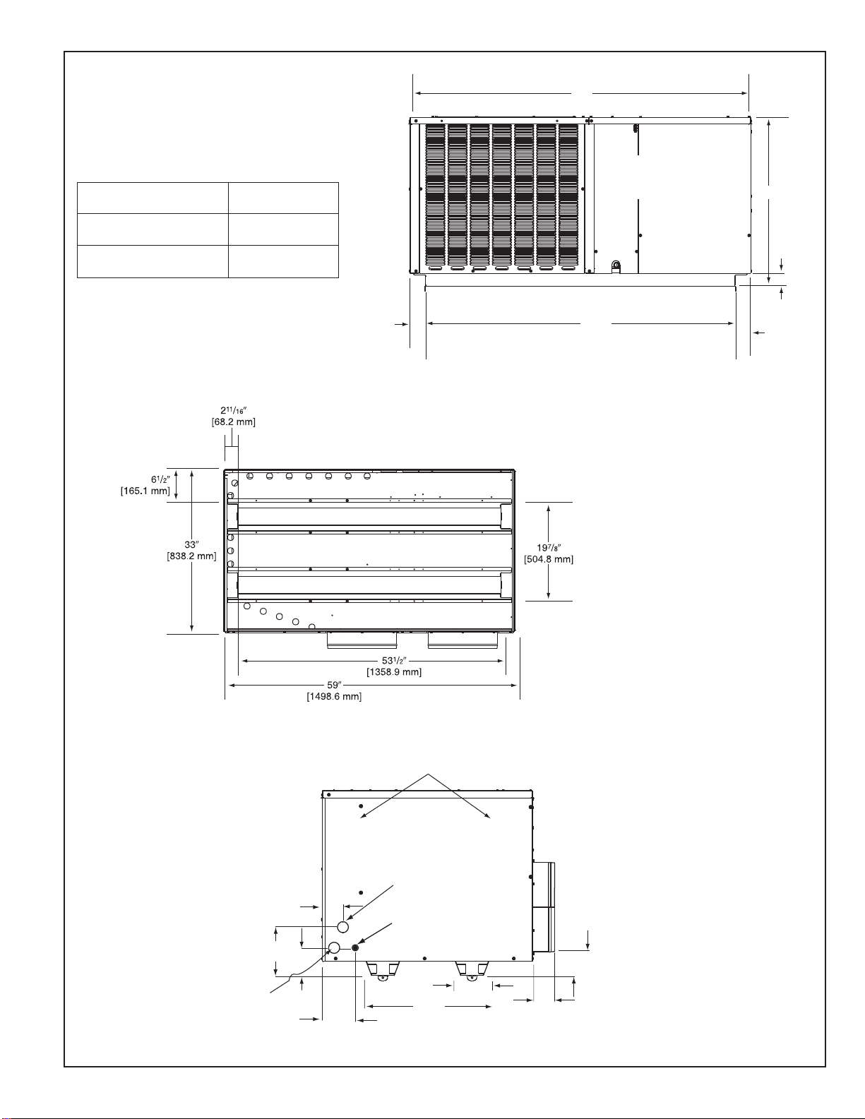
FIGURE 1
211/16"
[266.7 mm]
59"
[1498.6 mm]
53
1
/2"
[1358.9 mm]
3
1
/16"
[77.7 mm]
A
CONTROL
BOX ACCESS
211/16"
[266.7 mm]
CONDENSATE
DRAIN
PAN
ACCESS
PRIMARY
HIGH VOLTAGE
ENTRANCE
1
23
/32" [43.7 mm]
4
13
/32"
[111.8 mm]
5
9
/64"
[130.5 mm]
19
7
/8"
[505 mm]
57/8"
[149.5 mm]
3
1
/2"
[88.9 mm]
3
3
/4"
[95.3 mm]
721/32"
[194.3 mm]
313/64"
[81.2 mm]
AUXILIARY
HIGH VOLTAGE
ENTRANCE
1
23
/32" [43.7 mm]
LOW VOLTAGE
ENTRANCE
7
/8" [22.2 mm]
RECOMMENDED UNIT
DISCONNECT LOCATION
UNIT DIMENSIONS AND ACCESS LOCATIONS
Model Height “A”
FRONT VIEW
RQNM, RQPM: 024, 030 036
RQRM: 024
RQNM, RQPM: 042, 048, 060
RQRM: 030, 036, 042, 048, 060
29 1/8”
37 1/8”
BOTTOM VIEW
ELECTRICAL CONNECTIONS
5
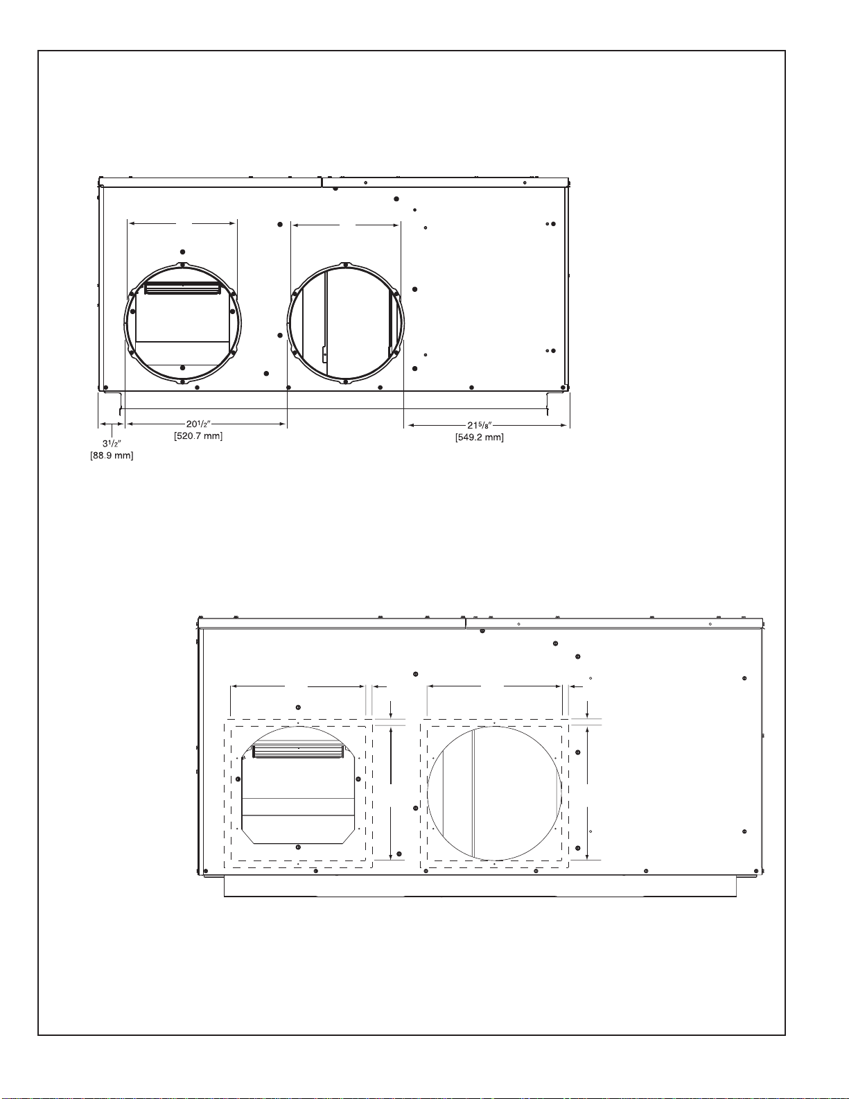
DUCT CONNECTIONS
14.00"
[355.6 mm]
14.00"
[355.6 mm]
[19.05 mm]
"
3
4
/
14.00"
[355.6 mm]
14.00"
[355.6 mm]
[19.05 mm]
"
3
4
/
IMPORTANT: DO NOT SCREW OR DRILL OUTSIDE THE DESIGNATED AREAS.
14"
[355.6 mm]
14"
[355.6 mm]
ROUND DUCT CONNECTIONS
IN THIS AREA
DO NOT DRILL OR INSTALL SCREWS
SQUARE DUCT CONNECTIONS
6
III. CHECKING PRODUCT RECEIVED
Upon receiving the unit, inspect it for any damage from shipment. Claims for damage,
either shipping or concealed, should be filed immediately with the shipping company.
Check the unit model number, heating size, electrical characteristics, and accessories to
determine if they are correct.
IV. EQUIPMENT PROTECTION FROM THE
ENVIRONMENT
The metal parts of this unit may be subject to rust or deterioration in adverse environmental conditions. This oxidation could shorten the equipment’s useful life. Salt spray, fog or
mist in seacoast areas, sulphur or chlorine from lawn watering systems, and various chemical contaminants from industries such as paper mills and petroleum refineries are especiallycorrosive.
If the unit is to be installed in an area where contaminants are likely to be a problem,
specialattentionshould be given to the equipmentlocation and exposure.
1. Avoidhaving lawnsprinklerheads spraydirectionon the unit cabinet.
2. In coastal areas, locate theunit on theside of the buildingaway fromthe waterfront.
3. Shielding provided bya fence orshrubs maygive someprotection.
4. Elevating the unit off its slab or base enough to allow air circulation will help avoid
holdingwater against thebasepan.
Regular maintenance will reduce the buildup of contaminents and help to protect
the unit’s finish.
WARNING
!
DISCONNECT ALL POWER TO THE UNIT BEFORE STARTING MAINTENANCE. FAILURE TO DO SO CAN RESULT IN SEVERE ELECTRICAL SHOCK
OR DEATH.
1. Frequent washing of the cabinet, fan blade and coil with fresh water will remove most
of thesalt or other contaminants that build up on the unit.
2. Regular cleaning and waxing of the cabinet with an automobile polish will provide
some protection.
3. A liquid cleaner may be used several times a year to remove matter that will not wash
off with water.
Several different types of protective coatings are offered in some areas. These coatings
may provide some benefit, but the effectiveness of such coating materials cannot be verified by the equipment manufacturer.
The best protection is frequent cleaning, maintenance and minimal exposure to
contaminants.
V. SPECIFICATIONS
Suitable for use in mobile homes, manufactured housing, and conventionally constructed
residential andcommercialbuildingswhere horizontally-ductedsystems arepreferred.
VI. INSTALLATION
A. GENERAL
1. PRE-INSTALLATION CHECK-POINTS
Before attempting any installation, the following points should be carefully considered:
a. Structural strength of supporting members.
(rooftop installation)
b. Clearances and provision for servicing.
c. Power supply and wiring.
d. Air duct connections.
e. Drain facilities and connections.
f. Location for minimum noise.
2. LOCATION
These units are designed for outdoor installations. They can be mounted on a
slab or rooftop. They are not to be installed within any part of a structure such as
an attic, crawl space, closet, or any other place where condenser air flow is
restricted or other than outdoor ambient conditions prevail. Since the application
of the units is of the outdoor type, it is important to consult your local code authorities at the time the first installation is made.
7
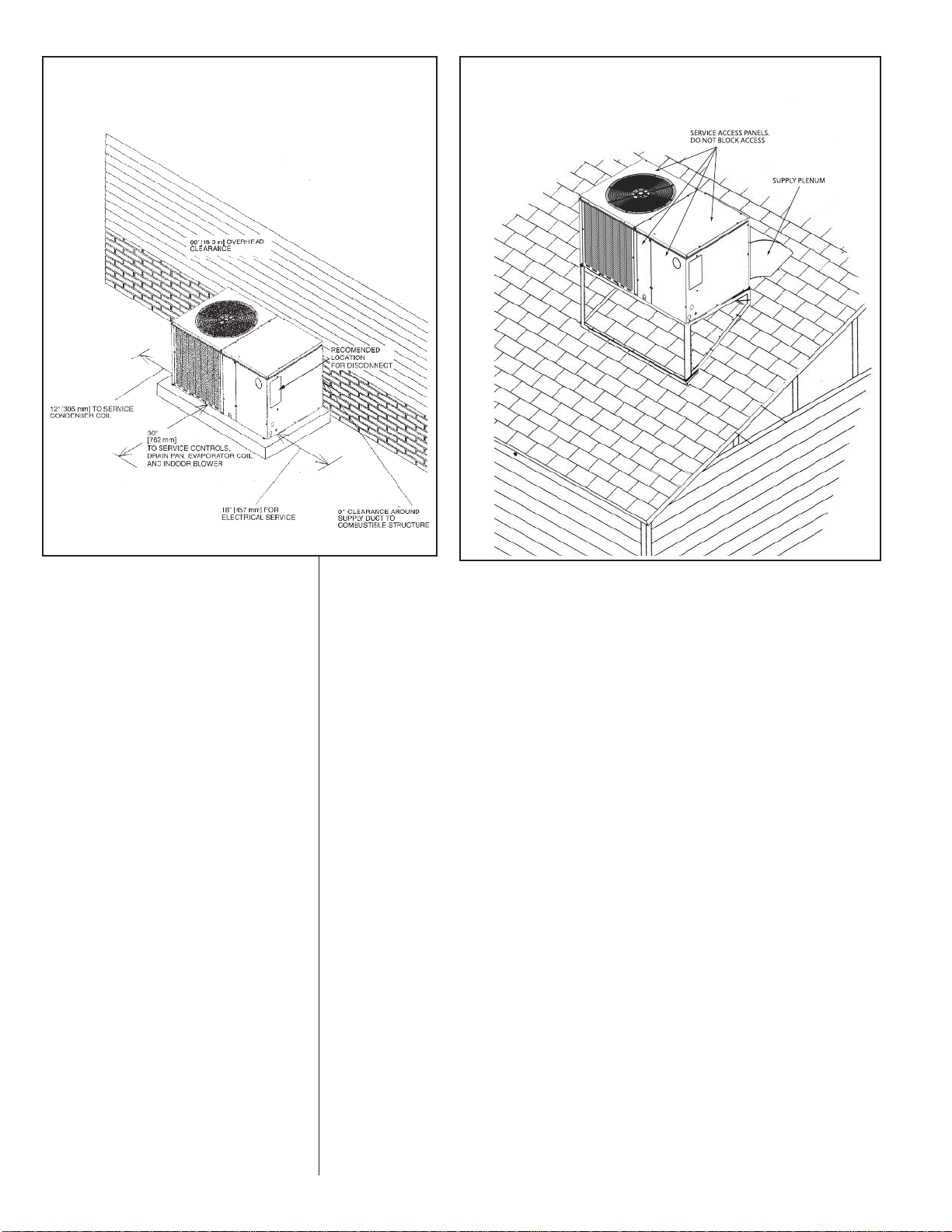
FIGURE 2
PACKAGED HEAT PUMP
OUTSIDE SLAB INSTALLATION, BASEMENT OR
CRAWL SPACE DISTRIBUTION SYSTEM
FIGURE 3
PACKAGED HEAT PUMP
PITCHED ROOFTOP INSTALLATION, ATTIC
OR DROP CEILING DISTRIBUTING SYSTEM.
MUST BE MOUNTED LEVEL.
B. OUTSIDE SLAB INSTALLATION
(Typical outdoor slab installations are shown in Figure 2.)
1. Select a location where external water drainage cannot collect around the unit.
2. Provide a level concrete slab extending 3" beyond all four sides of the unit. The
slab should be sufficient above grade to prevent ground water from entering the
unit.
IMPORTANT: To prevent transmission of noise or vibration, slab should not be
connected to building structure.
3. The location of the unit should be such as to provide proper access for inspection
and servicing.
4. Locate unit where operating sounds will not disturb owner or neighbors.
5. Locate unit so roof runoff water does not pour directly on the unit. Provide gutter
or other shielding at roof level. Do not locate unit in an area where excessive
snow drifting may occur or accumulate.
6. It is essential that the unit be elevated above the base pad to allow for condensate drainage and possible refreezing of condensation. Provide a base pad which
is slightly pitched away from the structure. Route condensate off base pad to an
area which will not become slippery and result in personal injury.
IMPORTANT: Avoid blocking openings in bottom of unit.
7. Where snowfall is anticipated, the height of the unit above the ground level must
be considered. Mount unit high enough to be above average area snowfall and to
allow for proper condensate drainage.
IMPORTANT: Avoid blocking openings in bottom of unit.
C. CLEARANCES
The following minimum clearances must be observed for proper unit performance
and serviceability.
1. Provide 30" minimum clearance at the front and 18" on the right side of the unit
for service access. Provide 12" minimum clearance on the left side of the unit for
air inlet.
2. Provide 60" minimum clearance from top of unit.
8
3. Unit is design certified for application on combustible flooring with 0" minimum
clearance.
4. See Figure 2 for illustration of minimum installation-service clearances.
D. ROOFTOP INSTALLATION
1. Before locating the unit on the roof, make sure that the strength of the roof and
beams is adequate at that point to support the weight involved. (See specification
sheet for weight of unit.) This is very important and user’s responsibility.
2. The unit should be placed on a solid and level platform of adequate strength.
IMPORTANT: Avoid blocking openings in bottom of unit. (See Figure 3).
Provision for disposal of outdoor coil defrost water runoff must be provided.
3. The location of the unit on the roof should be such as to provide proper access for
inspection and servicing.
IMPORTANT: If unit will not be put into service immediately, cover supply and return
openings to prevent excessive condensation.
VII. DUCTWORK
Ductwork should be fabricated by the installing contractor in accordance with local codes
and NFPA90A. Industry manuals may be used as a guide when sizing and designing the
duct system - contact Air Conditioning Contractors of America, 1513 16th St. N.W.,
Washington, D.C. 20036.
WARNING
!
DO NOT, UNDER ANY CIRCUMSTANCES, CONNECT RETURN DUCTWORK TO
ANY OTHER HEAT PRODUCING DEVICE SUCH AS A FIREPLACE INSERT,
STOVE, ETC. UNAUTHORIZED USE OF SUCH DEVICES MAY RESULT IN FIRE,
CARBON MONOXIDE POISONING, EXPLOSION, PROPERTY DAMAGE,
SEVERE PERSONAL INJURY OR DEATH.
Place the unit as close to the space to be air conditioned as possible allowing clearance
dimensions as indicated. Run ducts as directly as possible to supply and return outlets.
Use of non-flammable waterproof flexible connectors on both supply and return connections at the unit to reduce noise transmission is recommended.
It is preferable to install the unit on the roof of the structure if the registers or diffusers
are located on the wall or in the ceiling. Consider a slab installation when the registers
are low on a wall or in the floor.
On ductwork exposed to outside air conditions of temperature and humidity, use a minimum of 2" of insulation and a vapor barrier. Distribution system in attic, furred space or
crawl space should be insulated with at least 2" of insulation with vapor barrier. One-half
to 1" thickness of insulation is usually sufficient for ductwork inside the air conditioned
space.
Provide balancing dampers for each branch duct in the supply system. Properly support
the ductwork from the structure.
VIII.FILTERS
Filters are not provided with this unit. They must be supplied and installed in the return
air duct by the installer. A field installed filter grille is recommended for easy and convenient access to the filters for periodic inspection and cleaning. Filters must have adequate face area for the rated air quantity of the unit. See General Database for recommended filter size.
IX. CONDENSATE DRAIN
The indoor coil condensate drain ends with a PVC stub. A trap is provided in for proper
condensate drainage and to prevent debris from being drawn into the unit. Do not connect drain to closed sewer line. It is not recommended that a PVC cement or other permanent installation be used so that the drain line and/or drain pan can be easily cleaned
in the future. The drain trap is located in the control box during shipping. To install, slide
clear plastic tube over drain pan connection. The white PVC trap can be oriented as
required by installation.
9
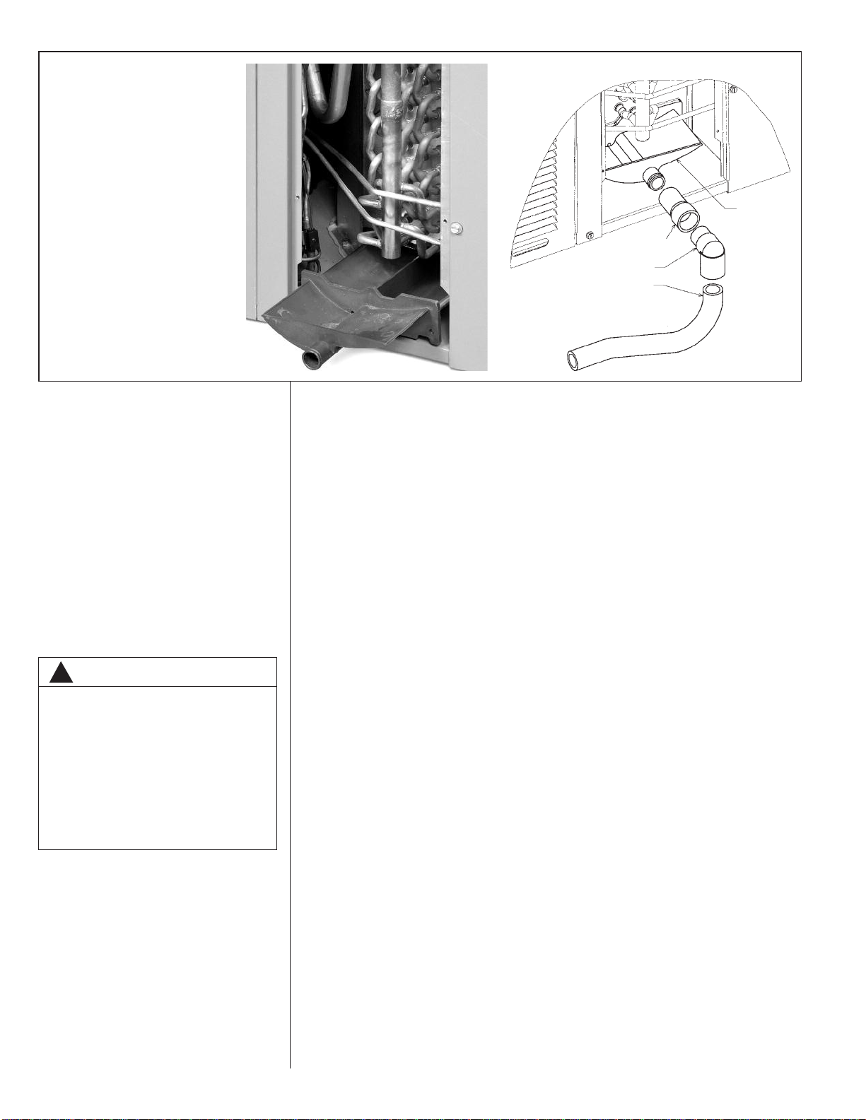
FIGURE 4
REMOVABLE CONDENSATE
DRAIN PAN AND REMOVAL
PROCEDURE
A small side panel grants
access to a removable, sloped
drain pan (A), which helps to
ensure indoor air quality (IAQ)
throughout the life of the unit. A
drain trap (B) assembly
is provided for
convenience.
CLEAR PVC
CONNECTOR TUBE
PVC ELBOW
PVC TRAP
DRAINPAN
“Patent 7,430,877”
WARNING
!
TURN OFF ELECTRIC POWER AT
THE FUSE BOX OR SERVICE
PANEL BEFORE MAKING ANY
ELECTRICAL CONNECTIONS.
ALSO, THE GROUND CONNECTION
MUST BE COMPLETED BEFORE
MAKING LINE VOLTAGE CONNECTIONS. FAILURE TO DO SO CAN
RESULT IN ELECTRICAL SHOCK,
SEVERE PERSONAL INJURY OR
DEATH.
A
B
X. CONDENSATE DRAIN, OUTDOOR COIL
The outdoor coil during heating operation will sweat or run water off. The outdoor coil will
also run water off during the defrost cycle. See Section V, Installation, for mounting precautions.
XI. ELECTRICAL WIRING
Field wiring must comply with the National Electrical Code* and applicable local codes.
*C.E.C. in Canada
A. POWER WIRING
1. It is important that proper electrical power is available at the unit. Voltage should
not vary more than 10% from that stamped on the unit rating plate. On three
phase units, phases must be balanced within 3%.
2. Install a branch circuit disconnect within sight of the unit and of adequate size to
handle the starting current. (See Heater Kit Tables.)
3. For branch circuit wiring (main power supply to unit disconnect), the minimum
wire size can be determined from the National Electrical Code or Canadian
Electrical Code or nameplate or from Heater Kit Tables.
4. This unit supports both single and dual point electrical connection for unit and
electric heat accessory.
5. Power wiring must be run in grounded rain-tight conduit.
B. POWER WIRING AND ELECTRIC HEATER KIT INSTRUCTIONS
1. Turn off power to unit.
2. Remove control box access panel.
3. Remove unit indoor section top cover.
4. Remove wire notch cover from control bulkhead and discard. Retain screw.
5. Remove heater element cover plate from blower outlet opening and discard. Retain
screws.
6. Mount heater fuse block assembly in location indicated with the three included
screws.
7. Route wire harness assembly through wire notch in control bulkhead and mount element assembly in blower outlet opening with screws previously retained.
8. Center wire routing plate over notch in blower bulkhead and secure with screw previously retained.
9. Route and tie wiring as shown in Figure 5. Wiring must not contact moving parts or
uninsulated electrical connections.
10. Replace unit indoor top cover.
11. Connect power and control wiring as indicated below:
a. Single-point wiring: Connect high voltage field power leads to heater kit fuse
block and connect included unit power pigtails from heater kit fuse block to unit
10
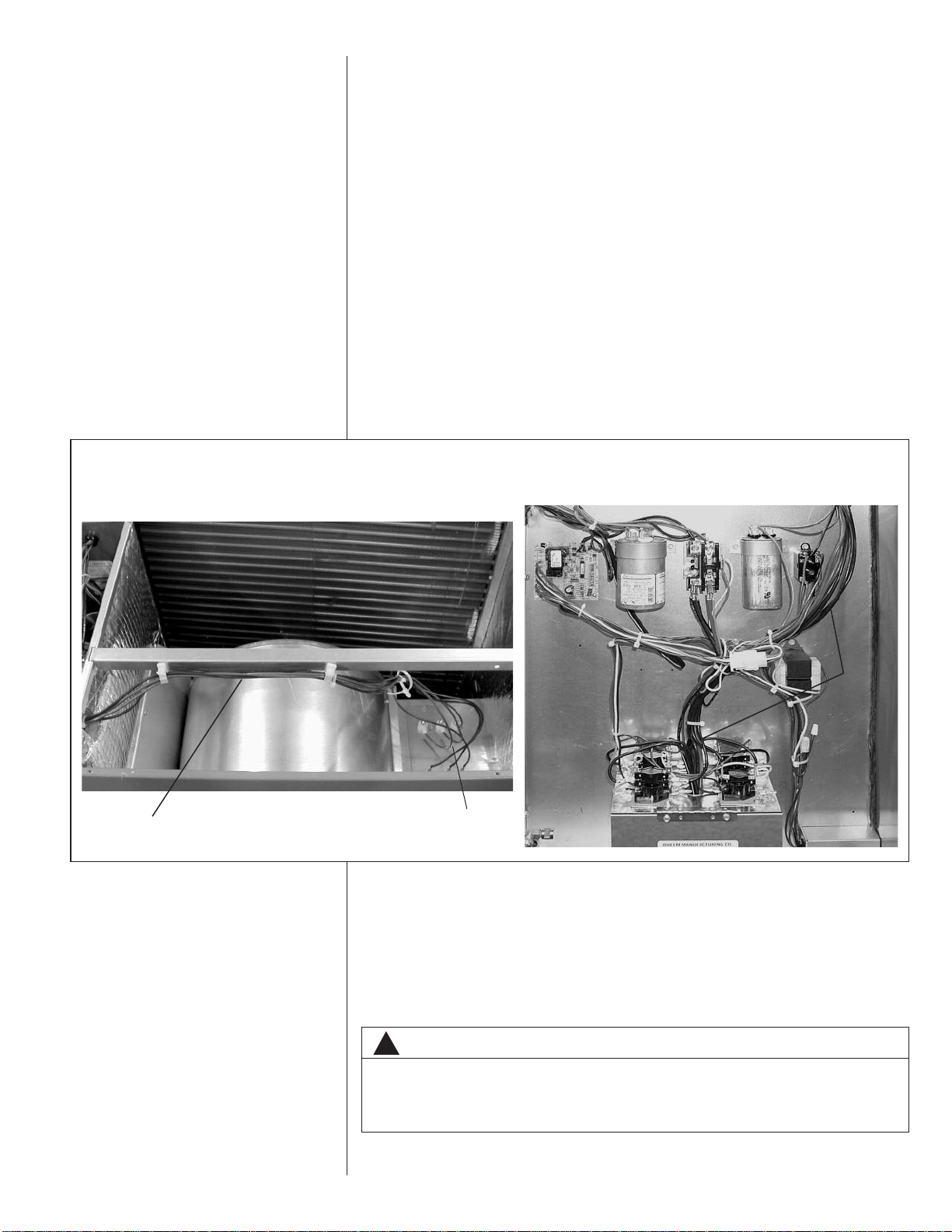
FIGURE 5
HEATER KIT INSTALLATION
contactor L1 and L3 connections. Connect ground lead to ground lug on heater kit
fuse block.
b. Dual-circuit wiring: Remove unit power pigtails from heater kit fuse block and
discard. Connect one set of high voltage field power circuit leads to the heater kit
fuse block and connect ground lead to ground lug on heater kit fuse block.
Connect the second set of high voltage field power leads to L1 and L3 on the unit
contactor. Connect ground lead to ground lug on control box bulkhead.
c. Connect heater kit control plug to receptacle in control box.
12. Replace control box access panel.
13. Restore power to unit and verify proper unit and heater kit operation.
C. CONTROL WIRING (Class II)
1. Do not run low voltage wiring in conduit with power wiring.
2. Control wiring is routed through the 7/8" hole corner adjacent to the control box.
See Electrical Connections, Figure 1. Use a minimum #18 AWG thermostat wire.
For wire lengths exceeding 50', use #16 AWG thermostat wire. The low voltage
wires are connected to the unit pigtails which are supplied with the unit in the low
voltage connection box located within the unit control box. See Figure 5.
3. It is necessary that only heat pump thermostats be used.
4. Figure 6 shows representative low voltage connection diagrams. Read your thermostat installation instructions for any special requirements for your specific thermostat.
RECOMMENDED
WIRING
HEATER
KIT
WIRING
HEATER
ELEMENTS
NOTE — Units installed in Canada require that an outdoor thermostat (30,000
min. cycles of endurance) be installed and be wired with C.E.C. Class I wiring.
D. INTERNAL WIRING
1. A diagram of the internal wiring of this unit is located on the electrical control box
cover. If any of the original wire as supplied with the appliance must be replaced,
the wire gauge and insulation must be the same as original wiring.
E. GROUNDING
WARNING
!
THE UNIT MUST BE PERMANENTLY GROUNDED. A GROUNDING LUG IS
PROVIDED. FAILURE TO GROUND THIS UNIT CAN RESULT IN FIRE OR ELECTRICAL SHOCK CAUSING PROPERTY DAMAGE, SEVERE PERSONAL INJURY
OR DEATH.
11
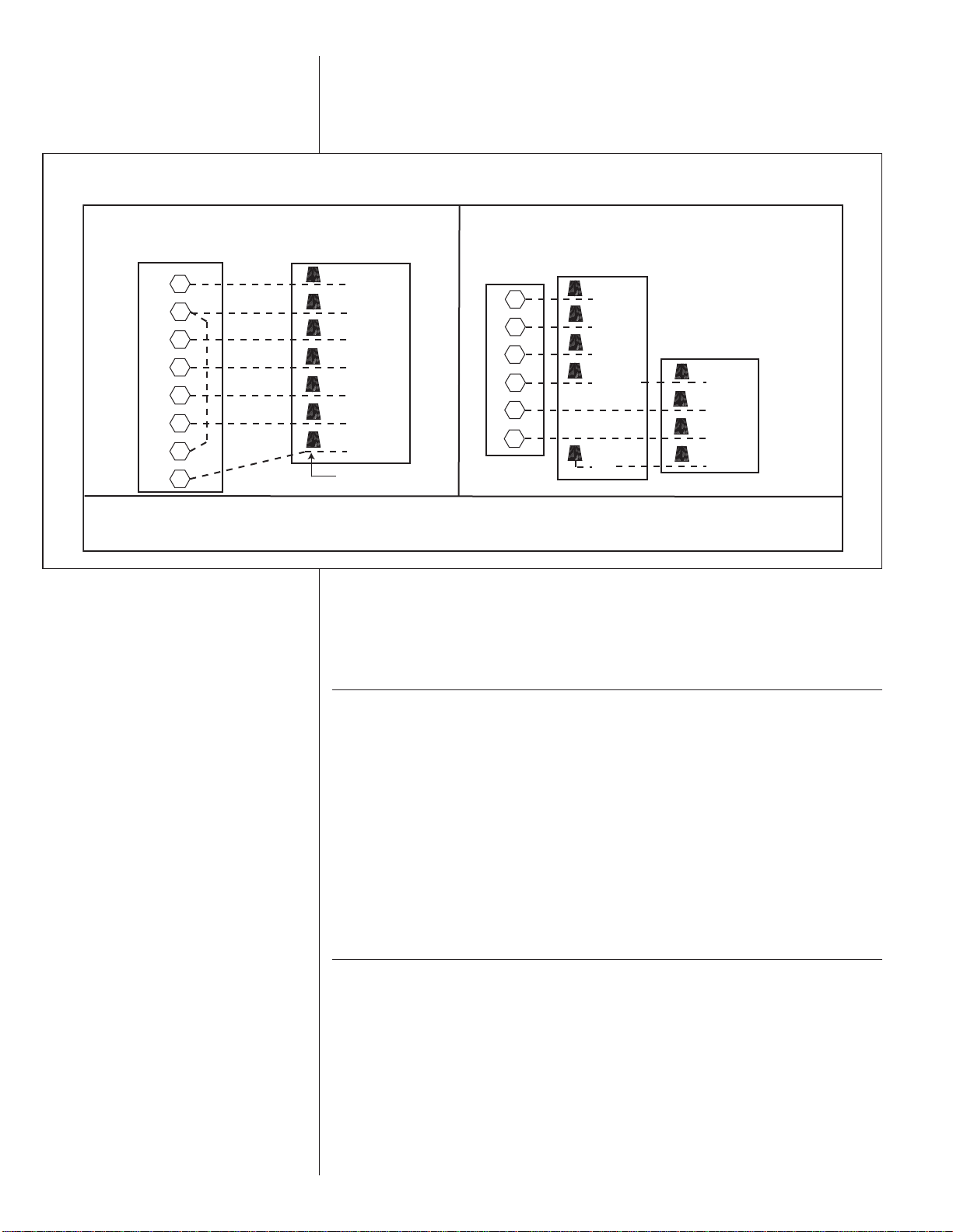
FIGURE 6
STANDARD
WITH ONE OUTDOOR THERMOSTAT W/EMERGENCY
HEAT RELAY
IF EMERGENCY HEAT RELAY AND OUTDOOR THERMOSTATS ARE NOT USED, A JUMPER BETWEEN “W2” AND “E” CAN BE
INSTALLED TO TRANSFER CONTROL OF HEATING TO THE FIRST STAGE WHEN THE SYSTEM SWITCH IS IN THE
EMERGENCY HEAT POSITION.
THERMOSTAT
SUB-BASE
UNIT CONTROL
WIRE PIGTAILS
OUTDOOR
THERMOSTAT
W/EMERGENCY
HEAT RELAY
THERMOSTAT
SUB-BASE
UNIT CONTROL
WIRE PIGTAILS
RED
PR
BROWN
BLUE
YELLOW
BK/Gr
Y/BL
RED
BK/GR
BLUE
BROWN
PU
BROWN
RED
WH
BL
G
E
Y
B
X
W2
R
Y2
R
G
B
X
E
W2
2 STAGE SYSTEM ONLY
VOLTAGE CONNECTIONS DIAGRAM
F. THERMOSTAT
Mount the thermostat on an inside wall about five feet above the floor in a location
where it will not be affected by unconditioned air, sun, or drafts from open doors or
other sources. READ installation instructions in heat pump thermostat package
CAREFULLY because each has some different wiring requirements.
XII. INDOOR AIR FLOW DATA
All 208/230 volt units are equipped with multi-speed indoor blower motors. Each unit is
shipped factory wired for the proper speed at a normal external static. See Airflow
Performance Table for blower performance.
XIII. PRE-START CHECK
1. Is unit properly located and level?
2. Is ductwork insulated, weatherproofed, with proper spacing to combustible materials?
3. Is air free to travel to and from outdoor coil? (See Figure 1.)
4. Is the wiring correct, tight, and according to unit wiring diagram?
5. Is unit grounded?
6. Are field supplied air filters in place and clean?
7. Do the outdoor fan and indoor blower turn freely without rubbing, and are they tight
on the motor shafts?
8. Is unit elevated to allow for outdoor coil condensate drainage during heating opera-
XIV.STARTUP
1. Turn thermostat to “OFF,” turn “on” power supply at disconnect switch.
2. Turn temperature setting as high as it will go.
3. Turn fan switch to “ON.”
4. Indoor blower should run. Be sure it is running in the right direction.
5. Turn fan switch to “AUTO.” Turn system switch to “COOL” and turn temperature set-
6. Is outdoor fan operating correctly in the right direction?
tion and defrost?
ting below room temperature. Unit should run in cooling mode.
12

7. Is compressor running correctly.
8. Turn thermostat system switch to “HEAT.” Unit should stop. Wait 5 minutes, then
raise temperature setting to above room temperature. Unit should run in heating
mode and after about 30 to 50 seconds auxiliary heaters, if installed, should come
on.
9. Check the refrigerant charge using the instructions located on control box cover.
Replace service port caps. Service port cores are for system access only and will
leak if not tightly capped.
Turn thermostat system switch to proper mode “HEAT” or “COOL” and set thermostat
10
to proper temperature setting. Record the following after the unit has run some time.
A. Operating Mode _______________________________
B. Discharge Pressure (High)___________________PSIG
C.Vapor Pressure at Compressor (Low) __________PSIG
D.Vapor Line Temperature at Compressor __________°F.
E. Indoor Dry Bulb______________________________°F.
F. Indoor Wet Bulb _____________________________°F.
G.Outdoor Dry Bulb ____________________________°F.
H.Outdoor Wet Bulb____________________________°F.
I. Voltage at Contactor ________________________Volts
J. Current at Contactor _______________________Amps
K. Model Number_________________________________
L. Serial Number _________________________________
M.Location______________________________________
N.Owner _______________________________________
O.Date_________________________________________
11. Adjust discharge air grilles and balance system.
12. Check ducts for condensation and air leaks.
13. Check unit for tubing and sheet metal rattles.
14. Instruct the owner on operation and maintenance.
15. Leave “USE AND CARE” instructions with owner.
XV. OPERATION
Most single phase units are not equipped with start relay or start capacitor. It is important that such systems be off for a minimum of 5 minutes before restarting to allow
equalization of pressures. Do not move the thermostat to cycle unit without waiting five
minutes. To do so may cause the compressor to stop on an automatic open overload
device or blow a fuse. Poor electrical service can cause nuisance tripping in overloads
or blow fuses.
IMPORTANT: The compressor has an internal overload protector. Under some conditions, it can take up to 2 hours for this overload to reset. Make sure overload has had
time to reset before condemning the compressor.
These units may be equipped with a time delay control (TDC1). The control allows the
blower to operate for 45 to 90 seconds after the thermostat is satisfied.
XVI. AUXILIARY HEAT
The amount of auxiliary heat required depends on the heat loss of the structure to be
heated and the capacity of the heat pump. It is good practice to install strip heat to maintain at least 60°F indoor temperatures in case of compressor failure. The auxiliary heat
is energized by the first stage of the thermostat. The amount of electric heat that is
allowed to come on, as determined by the output of the heat pump, may be controlled by
an outdoor thermostat.
WARNING
!
ONLY ELECTRIC HEATER KITS SUPPLIED BY THIS MANUFACTURER AS
DESCRIBED IN THIS PUBLICATION HAVE BEEN DESIGNED, TESTED, AND
EVALUATED BY A NATIONALLY RECOGNIZED SAFETY TESTING AGENCY
FOR USE WITH THIS UNIT. USE OF ANY OTHER MANUFACTURED ELECTRIC
HEATERS INSTALLED WITHIN THIS UNIT MAY CAUSE HAZARDOUS CONDITIONS RESULTING IN PROPERTY DAMAGE, FIRE, BODILY INJURY OR
DEATH.
A. CONTROL SYSTEM OPERATION
1. In the cooling mode, the thermostat will, on a call for cooling, energize the com-
pressor contactor and the indoor blower relay. The indoor blower can be operated
continuously by setting the thermostat fan switch at the “ON” position.
13

2. In the heating mode, the first heat stage of the thermostat will energize one or
more supplementary resistance heaters. If required or considered desirable, the
resistance heat may also be controlled by outdoor thermostats. In the heating
mode, the thermostat will, on a call for heating, energize the indoor blower relay.
XVII. DEMAND DEFROST CONTROL AND
HIGH/LOW PRESSURE CONTROLS
The demand defrost control is a printed circuit board assembly consisting of solid
state control devices with electro-mechanical outputs. The demand defrost control
monitors the outdoor ambient temperature, outdoor coil temperature, and the compressor run-time to determine when a defrost cycle is required.
Enhanced Feature Demand Defrost Control: Has high and low pressure control
inputs with unique pressure switch logic built into the microprocessor to provide
compressor and system protection without nuisance lock-outs. Cycles the compressor off for 30 seconds at the beginning and end of the defrost cycle to eliminate the
increased compressor noise caused by rapidly changing system pressures when
the reversing valve switches. See the end of this section for diagnostic flash codes
for the two diagnostic LED’s provided on the control.
DEFROST INITIATION
A defrost will be initiated when the three conditions below are satisfied:
1) The outdoor coil temperature is below 35°F.
2) The compressor has operated for at least 34 minutes with the outdoor coil temperature below 35°F.
3) The measured difference between the ambient temperature and the outdoor
coil temperature is greater than the calculated delta T.
Additionally, a defrost will be initiated if six hours of accumulated compressor runtime has elapsed without a defrost with the outdoor coil temperature below 35°F.
DEFROST TERMINATION
Once a defrost is initiated, the defrost will continue until fourteen minutes has
elapsed or the coil temperature has reached the terminate temperature. The terminate temperature is factory set at 70°F, although the temperature can be changed
to 50°F, 60°F, 70°F or 80°F by relocating a jumper on the board.
TEMPERATURE SENSORS
The coil sensor is clipped to the outdoor coil. The air sensor is located in the outdoor coil compartment.
If the ambient sensor fails the defrost control will initiate a defrost every 34 minutes
with the coil temperature below 35°F.
If the coil sensor fails the defrost control will not initiate a defrost.
TEST MODE
The test mode is initiated by shorting the TEST pins. In this mode of operation, the
enable temperature is ignored and all timers are sped up by a factor of 240. To initiate a manual defrost, short the TEST pins. Remove the short when the system
switches to defrost mode. The defrost will terminate on time (14 minutes) or when
the termination temperature has been achieved. Short TEST pins again to terminate the defrost immediately.
TROUBLE SHOOTING DEMAND DEFROST
Set the indoor thermostat select switch to heat and initiate a call for heat.
Jumper the “test pins” to put the unit into defrost. If the unit goes into defrost and
comes back out of defrost, the indication is that the control is working properly.
If the unit did not go into defrost using the test pins, check to ensure that 24V is
being supplied to the control board. If 24V is present then replace the control.
14
HIGH/LOW PRESSURE CONTROL MONITORING - ENHANCED
DEFROST CONTROL
Status of high and low pressure controls is monitored by the enhanced feature
demand defrost control and the following actions are taken.
High Pressure Control – Provides active protection in both cooling and heating
modes at all outdoor ambient temperatures. The high pressure control is an automatic reset type and opens at approximately 610 psig and closes at approximately
420 psig. The compressor and fan motor will stop when the high pressure control
opens and will start again if the high side pressure drops to approximately 420 psig
when the automatic reset high pressure control resets. If the high pressure control
opens 3 times within a particular call for heating or cooling operation, the defrost
control will lock out compressor and outdoor fan operation.
Low Pressure Control – Provides active protection in both heating and cooling
modes at all outdoor ambient temperatures. The low pressure control is an automatic reset type and opens at approximately 15 psig and closes at approximately
40 psig. Operation is slightly different between cooling and heating modes.
Cooling Mode: The compressor and fan motor will stop when the low pressure
control opens and will start again when the low side pressure rises to approximately 40 psig when the low pressure control automatically resets. If the low
pressure switch opens 3 times within a particular call for cooling operation, the
defrost control will lock out compressor and outdoor fan operation.
Heating Mode: The compressor and fan motor will stop when the low pressure
control opens and will start again when the low side pressure rises to approximately 40 psig when the low pressure control automatically resets. If the low
pressure switch trips 3 times within 120 minutes of operation during a particular
call for heating operation, the defrost control will lock out compressor and outdoor fan operation. If the lock-out due to low pressure occurs at an outdoor
ambient temperature below 5°F, the defrost control will automatically exit the
lock-out mode when the outdoor ambient temperature rises to 5°F. This feature
is necessary since the low pressure control could possibly have opened due to
the outdoor ambient being very low rather than an actual system fault.
Exiting Lock-Out Mode: To exit the lock-out mode, remove 24 volts to the defrost
control by removing power to indoor air-handler/furnace or by shorting the two
defrost control test pins together.
ENHANCED FEATURE DEFROST CONTROL DIAGNOSTIC CODES
LED 1 LED 2 Control Board Status
OFF OFF No Power
ON ON Coil Sensor Failure
OFF ON Ambient Sensor Failure
FLASH FLASH Normal
OFF FLASH Low Pressure Lockout (short test pins to reset)
FLASH OFF High Pressure Lockout (short test pins to reset)
ON FLASH Low Pressure Control Open
FLASH ON High Pressure Control Open
Alternate Flashing 5 Minute Time Delay
15

XVIII. GENERAL DATA - RQRM
NOMINAL SIZES 2.5-4 TONS [8.7-13.6 kW]
Model RQRM- Series A024JK A030JK A036JK A042JK
Cooling Performance
Gross Cooling Capacity Btu [kW] 24,400 [7.15] 29,600 [8.67] 35,000 [10.25] 43,000 [12.6]
EER, SEER
Nominal CFM/AHRI Rated CFM [L/s] 800/900 [378/425] 1000/1000 [472/472] 1200/1200 [566/566] 1400/1425 [661/672]
AHRI Net Cooling Capacity Btu [kW] 24,000 [7.03] 29,200 [8.56] 34,400 [10.08] 42,000 [12.31]
Net Sensible Capacity Btu [kW] 20,000 [5.86] 23,050 [6.75] 27,000 [7.91] 32,200 [9.43]
Net Latent Capacity Btu [kW] 4,000 [1.17] 6,150 [1.8] 7,400 [2.17] 9,800 [2.87]
Net System Power kW 1.85 2.13 2.58 3.14
Heating Performance [Heat Pumps]
High Temp. Btuh [kW] Rating 23,800 [6.97] 28,800 [8.44] 33,200 [9.73] 39,500 [11.57]
System Power KW / COP 1.79/3.9 2.11/4 2.63/3.7 2.89/4
Low Temp. Btuh [kW] Rating 11,700 [3.43] 16,000 [4.69] 18,600 [5.45] 22,400 [6.56]
System Power KW / COP 1.65/2.08 1.95/2.4 2.37/2.3 2.75/2.4
HSPF (Btu/Watts-hr) 8888.5
Compressor
No/Type 1/Scroll 1/Scroll 1/Scroll 1/Scroll
Outdoor Sound Rating (dB)
Outdoor Coil - Fin Type Louvered Louvered Louvered Louvered
Tube Type Rifled Rifled Rifled Rifled
Tube Size in. [mm] OD 0.375 [9.5] 0.375 [9.5] 0.375 [9.5] 0.375 [9.5]
Face Area sq. ft. [sq. m] 12.12 [1.13] 16.54 [1.54] 16.54 [1.54] 16.54 [1.54]
Rows / FPI [FPcm] 2 / 18 [7] 2 / 18 [7] 2 / 18 [7] 2 / 18 [7]
Refrigerant Control TX Valves TX Valves TX Valves TX Valves
Indoor Coil - Fin Type Louvered Louvered Louvered Louvered
Tube Type Rifled Rifled Rifled Rifled
Tube Size in. [mm] 0.375 [9.5] 0.375 [9.5] 0.375 [9.5] 0.375 [9.5]
Face Area sq. ft. [sq. m] 4.33 [0.4] 5.78 [0.54] 5.78 [0.54] 5.78 [0.54]
Rows / FPI [FPcm] 3 / 13 [5] 3 / 13 [5] 3 / 13 [5] 4 / 13 [5]
Refrigerant Control TX Valves TX Valves TX Valves TX Valves
Drain Connection No./Size in. [mm] 1/1 [25.4] 1/1 [25.4] 1/1 [25.4] 1/1 [25.4]
Outdoor Fan - Type Propeller Propeller Propeller Propeller
No. Used/Diameter in. [mm] 1/24 [609.6] 1/24 [609.6] 1/24 [609.6] 1/24 [609.6]
Drive Type/No. Speeds Direct/1 Direct/1 Direct/1 Direct/1
CFM [L/s] 3200 [1510]] 3200 [1510] 3200 [1510] 4200 [1982]
No. Motors/HP 1 at 1/3 HP 1 at 1/3 HP 1 at 1/3 HP 1 at 1/3 HP
Motor RPM 825 825 825 1075
Indoor Fan - Type FC Centrifugal FC Centrifugal FC Centrifugal FC Centrifugal
No. Used/Diameter in. [mm] 1/10x9 [254x229] 1/10x9 [254x229] 1/10x9 [254x229] 1/11x9 [279x229]
Drive Type/No. Speeds Direct/2 Direct/2 Direct/2 Direct/2
No. Motors 1111
Motor HP 1/2 1/2 1/2 3/4
Motor RPM 1050 1050 1050 1050
Motor Frame Size 48 48 48 48
Filter - Type Field Supplied Field Supplied Field Supplied Field Supplied
Furnished No No No No
(NO.) Size Recommended in. [mm x mm x mm] (1)1x20x16 [25x508x406] (1)1x20x20 [25x508x508] (1)1x24x24 [25x610x610] (1)1x24x24 [25x610x610]
Refrigerant Charge Oz. [g] 176 [4990] 203 [5755] 194 [5500] 206 [5840]
Weights
Net Weight lbs. [kg] 385 [175] 429 [195] 429 [195] 479 [217]
Ship Weight lbs. [kg] 409 [186] 455 [206] 455 [206] 505 [229]
1
2
5
13/16 13/16 13/16 13/16
76 76 76 78
Continued ->
NOTES:
1. Cooling Performance is rated at 95° F ambient, 80° F entering dry bulb, 67° F entering wet bulb. Gross capacity does not include the effect of fan motor heat. AHRI capacity is net and includes the effect of fan motor heat. Units are suitable for operation in CFM range shown in airflow tables. Units are certified in accordance with the Unitary
Air Conditioner Equipment certification program, which is based on AHRI Standard 210/240 or 360.
2. EER and/or SEER are rated at AHRI conditions and in accordance with DOE test procedures.
3. Heating Performance is rated at 47° F ambient, 70° F entering dry bulb for High Temp rating and 17° F ambient, 70° F entering dry bulb for Low Temp rating. Performance
ratings do include the effect of fan motor heat.
4. Outdoor Sound Rating shown is tested in accordance with AHRI Standard 270.
16

GENERAL DATA - RQRM
NOMINAL SIZES 2.5-4 TONS [8.7-13.6 kW]
Model RQRM- Series A048JK A060JK
Cooling Performance
Gross Cooling Capacity Btu [kW] 46,500 [13.62] 57,500 [16.85]
EER, SEER
Nominal CFM/AHRI Rated CFM [L/s] 1600/1525 [755/720] 2000/1900 [944/897]
AHRI Net Cooling Capacity Btu [kW] 45,500 [13.33] 56,000 [16.41]
Net Sensible Capacity Btu [kW] 34,700 [10.17] 41,450 [12.14]
Net Latent Capacity Btu [kW] 10,800 [3.16] 14,550 [4.26]
Net System Power kW 3.45 4.63
Heating Performance [Heat Pumps]
High Temp. Btuh [kW] Rating 43,500 [12.75] 54,800 [16.06]
System Power KW / COP 3.19/4 4.2/3.82
Low Temp. Btuh [kW] Rating 23,800 [6.97] 31,600 [9.26]
System Power KW / COP 2.79/2.5 3.65/2.54
HSPF (Btu/Watts-hr) 8.5 8.5
Compressor
No/Type 1/Scroll1/Scroll 1/Scroll
Outdoor Sound Rating (dB)
Outdoor Coil - Fin Type Louvered Louvered
Tube Type Rifled Rifled
Tube Size in. [mm] OD 0.375 [9.5] 0.375 [9.5]
Face Area sq. ft. [sq. m] 16.54 [1.54] 16.54 [1.54]
Rows / FPI [FPcm] 2 / 18 [7] 2 / 18 [7]
Refrigerant Control TX Valves TX Valves
Indoor Coil - Fin Type Louvered Louvered
Tube Type Rifled Rifled
Tube Size in. [mm] 0.375 [9.5] 0.375 [9.5]
Face Area sq. ft. [sq. m] 5.78 [0.54] 5.78 [0.54]
Rows / FPI [FPcm] 4 / 13 [5] 4 / 13 [5]
Refrigerant Control TX Valves TX Valves
Drain Connection No./Size in. [mm] 1/1 [25.4] 1/1 [25.4]
Outdoor Fan - Type Propeller Propeller
No. Used/Diameter in. [mm] 1/24 [609.6] 1/24 [609.6]
Drive Type/No. Speeds Direct/1 Direct/1
CFM [L/s] 4200 [1982] 4200 [1982]
No. Motors/HP 1 at 1/3 HP 1 at 1/3 HP
Motor RPM 1075 1075
Indoor Fan - Type FC Centrifugal FC Centrifugal
No. Used/Diameter in. [mm] 1/11x9 [279x229] 1/11x9 [279x229]
Drive Type/No. Speeds Direct/2 Direct/2
No. Motors 11
Motor HP 3/4 1
Motor RPM 1050 1050
Motor Frame Size 48 48
Filter - Type Field Supplied Field Supplied
Furnished No No
(NO.) Size Recommended in. [mm x mm x mm] (1)1x24x24 [25x610x610] (1)1x24x24 [25x610x610]
Refrigerant Charge Oz. [g] 216 [6124] 202 [5727]
Weights
Net Weight lbs. [kg] 481 [218] 482 [219]
Ship Weight lbs. [kg] 507 [230] 508 [230]
1
2
5
13/16 12/15
78 78
NOTES:
1. Cooling Performance is rated at 95° F ambient, 80° F entering dry bulb, 67° F entering wet bulb. Gross capacity does not include the effect of fan motor heat. AHRI capacity is net and includes the effect of fan motor heat. Units are suitable for operation in CFM range shown in airflow tables. Units are certified in accordance with the Unitary
Air Conditioner Equipment certification program, which is based on AHRI Standard 210/240 or 360.
2. EER and/or SEER are rated at AHRI conditions and in accordance with DOE test procedures.
3. Heating Performance is rated at 47° F ambient, 70° F entering dry bulb for High Temp rating and 17° F ambient, 70° F entering dry bulb for Low Temp rating. Performance
ratings do include the effect of fan motor heat.
4. Outdoor Sound Rating shown is tested in accordance with AHRI Standard 270.
17

GENERAL DATA - RQPM
NOMINAL SIZES 2-5 TONS [7-17.6 kW]
Model RQPM- Series A024JK A030JK A036CK A036JK
Cooling Performance
Gross Cooling Capacity Btu [kW] 24,000 [7.03] 29,400 [8.61] 36,000 [10.55] 36,000 [10.55]
EER, SEER
Nominal CFM/AHRI Rated CFM [L/s] 800/800 [378/378] 1000/1000 [472/472] 1200/1200 [566/566] 1200/1200 [566/566]
AHRI Net Cooling Capacity Btu [kW] 23,600 [6.91] 29,000 [8.5] 35,400 [10.37] 35,400 [10.37]
Net Sensible Capacity Btu [kW] 18,400 [5.39] 23,000 [6.74] 27,600 [8.09] 27,600 [8.09]
Net Latent Capacity Btu [kW] 5,200 [1.52] 6,000 [1.76] 7,800 [2.29] 7,800 [2.29]
Net System Power kW 2 2.41 3.05 3.05
Heating Performance [Heat Pumps]
High Temp. Btuh [kW] Rating 23,200 [6.8] 28,000 [8.2] 34,200 [10.02] 34,200 [10.02]
System Power KW / COP 1.93/3.5 2.27/3.62 2.78/3.6 2.78/3.6
Low Temp. Btuh [kW] Rating 13,200 [3.87] 15,200 [4.45] 19,000 [5.57] 19,000 [5.57]
System Power KW / COP 1.71/2.26 2.01/2.22 2.48/2.24 2.48/2.24
HSPF (Btu/Watts-hr) 8888
Compressor
No/Type 1/Copeland Scroll 1/Copeland Scroll 1/Copeland Scroll 1/Copeland Scroll
Outdoor Sound Rating (dB)
Outdoor Coil - Fin Type Louvered Louvered Louvered Louvered
Tube Type Rifled Rifled Rifled Rifled
Tube Size in. [mm] OD 0.375 [9.5] 0.375 [9.5] 0.375 [9.5] 0.375 [9.5]
Face Area sq. ft. [sq. m] 10.44 [0.97] 12.65 [1.18] 12.65 [1.18] 12.65 [1.18]
Rows / FPI [FPcm] 1 / 20 [8] 1 / 20 [8] 1 / 20 [8] 1 / 20 [8]
Refrigerant Control TX Valves TX Valves TX Valves TX Valves
Indoor Coil - Fin Type Louvered Louvered Louvered Louvered
Tube Type Rifled Rifled Rifled Rifled
Tube Size in. [mm] 0.375 [9.5] 0.375 [9.5] 0.375 [9.5 0.375 [9.5]
Face Area sq. ft. [sq. m] 4.33 [0.4] 4.33 [0.4] 4.33 [0.4] 4.33 [0.4]
Rows / FPI [FPcm] 2 / 15 [6] 3 / 13 [5] 3 / 13 [5] 3 / 13 [5]
Refrigerant Control TX Valves TX Valves TX Valves TX Valves
Drain Connection No./Size in. [mm] 1/1 [25.4] 1/1 [25.4] 1/1 [25.4] 1/1 [25.4]
Outdoor Fan - Type Propeller Propeller Propeller Propeller
No. Used/Diameter in. [mm] 1/24 [609.6] 1/24 [609.6] 1/24 [609.6] 1/24 [609.6]
Drive Type/No. Speeds Direct/1 Direct/1 Direct/1 Direct/1
CFM [L/s] 3200 [1510] 3200 [1510] 3200 [1510] 3200 [1510]
No. Motors/HP 1 at 1/3 HP 1 at 1/3 HP 1 at 1/3 HP 1 at 1/3 HP
Motor RPM 825 825 825 825
Indoor Fan - Type FC Centrifugal FC Centrifugal FC Centrifugal FC Centrifugal
No. Used/Diameter in. [mm] 1/10x9 [254x229] 1/10x9 [254x229] 1/10x9 [254x229] 1/10x9 [254x229]
Drive Type/No. Speeds Direct/2 Direct/2 Direct/2 Direct/2
No. Motors 1111
Motor HP 1/2 1/2 1/2 1/2
Motor RPM 1050 1050 1050 1050
Motor Frame Size 48 48 48 48
Filter - Type Field Supplied Field Supplied Field Supplied Field Supplied
Furnished No No No No
(NO.) Size Recommended in. [mm x mm x mm] (1)1x20x16 [25x508x406] (1)1x20x20 [25x508x508] (1)1x24x24 [25x610x610] (1)1x24x24 [25x610x610]
Refrigerant Charge Oz. [g] 90 [2552] 93 [2637] 93 [2637] 93 [2637]
Weights
Net Weight lbs. [kg] 308 [140[ 331 [150] 356 [161] 356 [161]
Ship Weight lbs. [kg] 332 [151] 355 [161] 380 [172] 380 [172]
1
2
5
12/14 12.05/14 11.6/14 11.6/14
76 76 76 76
Continued ->
NOTES:
1. Cooling Performance is rated at 95° F ambient, 80° F entering dry bulb, 67° F entering wet bulb. Gross capacity does not include the effect of fan motor heat. AHRI capacity is net and includes the effect of fan motor heat. Units are suitable for operation in CFM range shown in airflow tables. Units are certified in accordance with the Unitary
Air Conditioner Equipment certification program, which is based on AHRI Standard 210/240 or 360.
2. EER and/or SEER are rated at AHRI conditions and in accordance with DOE test procedures.
3. Heating Performance is rated at 47° F ambient, 70° F entering dry bulb for High Temp rating and 17° F ambient, 70° F entering dry bulb for Low Temp rating. Performance
ratings do include the effect of fan motor heat.
4. Outdoor Sound Rating shown is tested in accordance with AHRI Standard 270.
18
 Loading...