

Page 1
RQPW-B
Parts List
13-January-2016
This parts list is current as of the above revision date.
See http://www.rheempartslists.net/92-42800-RQPW-B.pdf for the current revision.
Package Dual Fuel
Page 2

Table of Contents
Model Explanation................. . . . . . . . . . . . . . . . . . . . . ............................ . . . . . . . . . . . . . . . . . . . . ............................ . . Page 3
Parts Numbers
Panels - Miscellaneous .. . . . . . ........................... . . . . . . . . . . . . . . . . . . . . . ........................... . . . . . . . . Page4
Electrical Group . . . . . . . ........................... . . . . . . . . . . . . . . . . . . . . . ........................... . . . . . . . . . . . . . . . Page 5
Fan Group............... . . . . . . . . . . . . . . . . . . . . . ........................... . . . . . . . . . . . . . . . . . . . . . ................... Page 6
Blower Group.. . . . . . . . . . . . . . . . . . . . . ............................ . . . . . . . . . . . . . . . . . . . . ............................ . . Page6
Coil Parts .................. . . . . . . . . . . . . . . . . . . . . ............................ . . . . . . . . . . . . . . . . . . . . ................. Page 7
Compressor Group ... . . . . . . . . . . . . . . . . . . . . ............................ . . . . . . . . . . . . . . . . . . . . ....................... Page 7
Heat Exchanger-Burner Group.................. . . . . . . . . . . . . . . . . . . . . . ........................... . . . . . . . . . . . . . . . . . Page 8
Gas Controls .. . . . . . . . . . . . . . . . . . . . . . ........................... . . . . . . . . . . . . . . . . . . . . . ........................... . . Page9
Accessories .. . . . . . . . . . . . . . . . . . . . . . ........................... . . . . . . . . . . . . . . . . . . . . . ........................... . . . Page9
Orifice Selection Chart.................. . . . . . . . . . . . . . . . . . . . . . ........................... . . . . . . . . . . . . . . . . . . . . . ... Page10
Drawings/Photographs
Exploded View .. . . . . ............................ . . . . . . . . . . . . . . . . . . . . ............................ . . . . . . . . . . . . . . . Page 11
Control Access Panel Detail .................. . . . . . . . . . . . . . . . . . . . . . ........................... . . . . . . . . . . . . . . . . . . Page 12
Control Box Assembly ................................................... . . . . . . . . . . . . . . . . . . . . . .................. Page 13
Blower Assembly . . . . . . ........................... . . . . . . . . . . . . . . . . . . . . . ........................... . . . . . . . . . . . . . . Page 14
EvaporatorCoil Assembly . . . . . . . ........................... . . . . . . . . . . . . . . . . . . . . . ........................... . . . . . Page 15
Condenser Coil................. . . . . . . . . . . . . . . . . . . . . . ........................... . . . . . . . . . . . . . . . . . . . . . ........... Page 16
Compressor and Refrigeration Components.................... . . . . . . . . . . . . . . . . . . . . ............................ . Page 17
Heat Exchanger Assembly.................. . . . . . . . . . . . . . . . . . . . . . ........................... . . . . . . . . . . . . . . . . . . . . Page18
Burner Assembly (Inshot - Before Approx F3708)................... . . . . . . . . . . . . . . . . . . . . . ........................ Page 19
Burner Assembly (One-piece - After Approx F3708) ...... . . . . . . . . . . . . . . . . . . . . ............................ . . . . . . . Page 20
Notes/Disclaimer . . . . . . . . ........................... . . . . . . . . . . . . . . . . . . . . . ........................... . . . . . . . . . . . . . . . . . . . . . ........... Page 21
Page 2 of 21
13-January-2016
92-42800-RQPW-B
Page 3
R Q P W - B 0 3 6 J K 10 E B V A
(1) (2) (3) (4) (5) (6) (7) (8) (9) (10) (11)
(1) TRADENAME IDENTIFICATION (8) DRIVE PACKAGE
K = DIRECT DRIVE
(2) PRODUCT CLASSIFICATION
Q = HEAT PUMP - SELF CONTAINED (9) HEATING CAPACITY - (MBH)
04 = 40,000
(3) EFFICIENCY DESIGNATION 06 = 60,000
P = 14 SEER 08 = 80,000
10 = 100,000
(4) DESIGN SERIES
W = DUAL FUEL (10) IGNITION SYSTEM
E = ELECTRIC
(5) TECHNICALVARIATIONS X = ELECTRIC NOX
(6) COOLING CAPACITY (BTU/HR) (11) OPTION CODES
024 = 24,000 042 = 42,000 BVA = SIDEFLOW W/
025 = 24,000 048 = 48,000
030 - 30,000 STAINLESS STEEL
036 = 36,000 HEAT EXCHANGER
(7) ELECTRICAL DESIGNATION
J = 208/230V - 1 PH - 60 HZ.
C = 208/230V - 3 PH - 60 HZ.
1 R A 1 2 3 4 A D A A F 2 6 0 6 0 0 0 1
(1) (2) (3) (4) (5) (6) (7) (8) (9) (10) (11)
(1) GAS CODE (7) TECHNOLOGY VARIATIONS
(2) BLOWER CONTROL BOARD (8) PLANT
F = FORT SMITH, AR
(3) COMPRESSOR IDENTIFICATION NUMBER
(9) WEEK
(4) IGNITION DEVICE
(10) YEAR
(5) INDUCER BLOWER
(11) PRODUCTION NUMBER
(6) HEAT EXCHANGER:
F 0 8 1 3 9 9 9 9
(1) (2) (3) (4)
(1) PLANT CODE
(2) WEEK (DATE CODE)
(3) YEAR
(4) PRODUCTION NUMBER
Note: For Compressor Identification Number, see Compressor Code on Rating Plate
For Gas Code, see Control System Gas Code on Rating Plate
SERIAL NUMBER EXPLANATION (Units Produced before Nov. 2013)
SERIAL NUMBER EXPLANATION (Units Produced after Nov.2013)
MODEL NUMBER EXPLANATION
Page 3 of 21
13-January-2016
92-42800-RQPW-B
Page 4
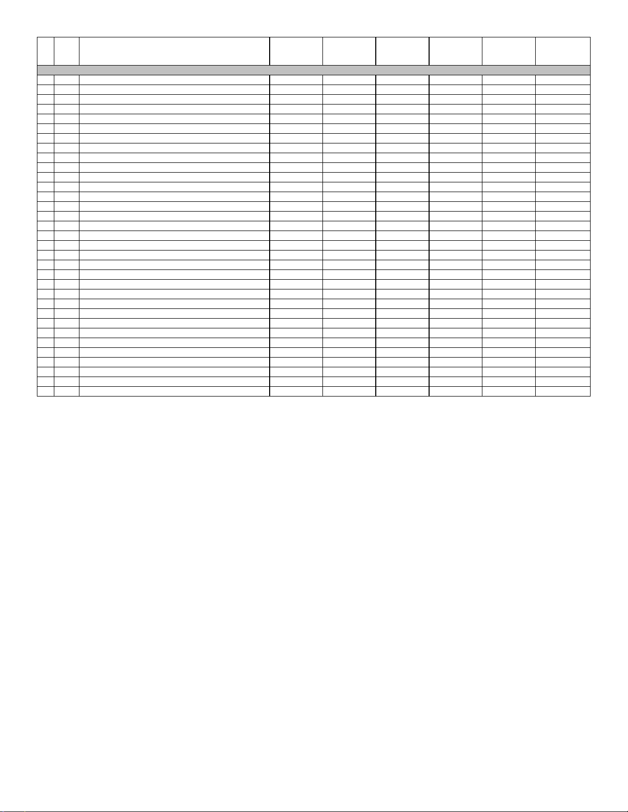
No. Notes
1 Front Base Pan AS-58628-06A AS-58628-06A AS-58628-06A AS-58628-06A AS-58628-06A AS-58628-06
2 Base Rail (2) AE-58562-03 AE-58562-03 AE-58562-03 AE-58562-03 AE-58562-03 AE-58562-03
3 Base Rail (2) AE-58562-04 AE-58562-04 AE-58562-04 AE-58562-04 AE-58562-04 AE-58562-04
4 Back Base Pan AS-58607-64 AS-58607-64 AS-58607-64 AS-58607-64 AS-58607-64 AS-58607-64
5 Blower Shelf AS-58630-01 AS-58630-01 AS-58630-01 AS-58630-01 AS-58630-01 AS-58630-01
6 Blower Shelf Transition AS-58607-19 AS-58607-19 AS-58607-19 AS-58607-19 AS-58607-19 AS-58607-19
7 Divider Panel AS-58607-03 AS-58607-03 AS-58607-03 AS-58607-03 AS-58607-03 AS-58607-03
8 Bulkhead Assembly AS-58607-55 AS-58607-55 AS-58607-57 AS-58607-63 AS-58607-57 AS-58607-57
9 Exhaust Hood AS-58629-01A AS-58629-01A AS-58629-01A AS-58629-01A AS-58629-01A AS-58629-01
10 Combustion Air Inlet Hood AS-58599-01A AS-58599-01A AS-58599-01A AS-58599-01A AS-58599-01A AE-58599-01
11 Corner Post AS-58607-40 AS-58607-40A AS-58607-46A AS-58607-46A AS-58607-46A AS-58607-46A
12 Blower Access Panel AS-58607-09 AS-58607-09A AS-58607-47A AS-58607-47A AS-58607-47A AS-58607-47A
13 End Panel AS-58607-04 AS-58607-04A AS-58607-48A AS-58607-48A AS-58607-48A AS-58607-48A
14 Supply Cover - Downflow AS-58607-06 AS-58607-06A AS-58607-06A AS-58607-06A AS-58607-06A AS-58607-06A
14 Supply Cover - Side Option "BVA" AS-58607-35A N/A AS-58607-35A AS-58607-35A AS-58607-35A AS-58607-35A
15 Return Cover - Downflow AS-58607-05 AS-58607-05A AS-58607-05A AS-58607-05A AS-58607-05A AS-58607-05A
15 Return Cover - Side Option "BVA" AS-58607-34A N/A AS-58607-34A AS-58607-34A AS-58607-34A AS-58607-34A
16 TopPanel AS-58607-58 AS-58607-58A AS-58607-54A AS-58607-59A AS-58607-54A AS-58607-54A
17 Grille 95-100906-08 95-100906-08 95-100906-08 95-100906-08 95-100906-08 95-100906-08
18 Filter Access Panel AS-58607-08 AS-58607-08A AS-58607-49A AS-58607-49A AS-58607-49A AS-58607-49A
19 Condenser Louver Panel AS-58607-61 AS-58607-61A AS-58607-56A AS-58607-56A AS-58607-56A AS-58607-56A
20 Center Post AE-58569-05 AE-58569-05 AS-58569-07A AS-58569-07A AS-58569-07A AS-58569-07A
21 Control Access Panel AS-58607-20 AS-58607-20A AS-58607-50A AS-58607-50A AS-58607-50A AS-58607-50A
22 Control Box - (w/o components) AE-58597-01 AE-58597-01 AE-58597-01 AE-58597-01 AE-58597-01 AE-58597-01
23 Control Box Cover AE-58598-01 AE-58598-01 AE-58598-01 AE-58598-01 AE-58598-01 AE-58598-01
24 Furnace Shelf AS-58607-11 AS-58607-11 AS-58607-11 AS-58607-11 AS-58607-11 AS-58607-11
25 Burner Floor AE-58594-01 AE-58594-01 AE-58594-01 AE-58594-01 AE-58594-01 AE-58594-01
26 Exhaust Transition AS-58607-36 AS-58607-36 AS-58607-36 AS-58607-36 AS-58607-36 AS-58607-36
27 Bulkhead Valve (2) 61-22369-04 61-22369-04 61-22369-04 61-22369-04 61-22369-04 61-22369-04
28 Bulkhead Valve Locknut (2) 63-22368-01 63-22368-01 63-22368-01 63-22368-01 63-22368-01 63-22368-01
Bulkhead ValveCap (2) 83-100635-01 83-100635-01 83-100635-01 83-100635-01 83-100635-01 83-100635-01
Heat Exchanger Tube Support AE-58590-01 AE-58590-01 AE-58590-01 AE-58590-01 AE-58590-01 AE-58590-01
Grommet - Gas Supply Piping 56-22114-01 56-22114-01 56-22114-01 56-22114-01 56-22114-01 56-22114-01
MODEL
TECHNICALVARIATION
COOLING CAPACITY
PANELS, MISCELLANEOUS PARTS
RQPW
B
024
RQPW
B
025
RQPW
B
030
RQPW
B
036
RQPW
B
042
RQPW
B
048
Page 4 of 21
13-January-2016
92-42800-RQPW-B
Page 5
MODEL
No. Notes
31 Stk Induced Draft Blower w/Gasket 70-23641-01 70-23641-01 70-23641-01 70-23641-01 70-23641-01 70-23641-01
Gasket - Induced Draft Blower 68-23643-01 68-23643-01 68-23643-01 68-23643-01 68-23643-01 68-23643-01
32 Stk,5
32 Stk,5
33 Stk Contactor 42-102289-01 42-102289-01 42-102289-01 42-102289-01 42-102289-01 42-102289-01
34 Stk Pressure Switch 42-24335-20 42-24335-20 42-24335-20 42-24335-20 42-24335-20 42-24335-20
35 Stk Transformer 46-100836-05 46-100836-05 46-100836-05 46-100836-05 46-100836-05 46-100836-05
36 Ground Lug 45-19000-01 45-19000-01 45-19000-01 45-19000-01 45-19000-01 45-19000-01
37 Capacitor Adaptor Plate (2 in. round capacitor) AE-54609-01 AE-54609-01 AE-54609-01 AE-54609-01 AE-54609-01 AE-54609-01
37
38 Stk Relay - Blower Motor 42-101208-02 42-101208-02 42-101208-02 42-101208-02 42-101208-02 42-101208-02
39 Integrated Furnace Control Board (IFC) See Gas Controls
78 Capacitor - Compressor/Fan See Compressor Group
84 Limit Control - Blower Shelf See Heat Exchanger-Burner Group
88 Limit Control - Roll Out See Heat Exchanger-Burner Group
Compressor Wiring Harness (Molded Plug) See Compressor Group
Wiring Harness - 9 pin to 9 insulated terminals AS-102393-02 AS-102393-02 AS-102393-02 AS-102393-02 AS-102393-02 AS-102393-02
No. Notes
31 Stk Induced Draft Blower w/Gasket 70-23641-01 70-23641-01 70-23641-01
Gasket - Induced Draft Blower 68-23643-01 68-23643-01 68-23643-01
32 Stk,5
32 Stk,5
33 Stk Contactor 42-42667-02 42-42667-02 42-42667-02
34 Stk Pressure Switch 42-24335-20 42-24335-20 42-24335-20
35 Stk Transformer 46-100836-05 46-100836-05 46-100836-05
36 Ground Lug 45-19000-01 45-19000-01 45-19000-01
37 Capacitor Adaptor Plate (2 in. round capacitor) AE-54609-01 AE-54609-01 AE-54609-01
37
38 Stk Relay - Blower Motor 42-101208-02 42-101208-02 42-101208-02
39 Integrated Furnace Control Board (IFC) See Gas Controls
78 Capacitor - FanMotor See FanGroup
84 Limit Control - Blower Shelf See Heat Exchanger-Burner Group
88 Limit Control - Roll Out See Heat Exchanger-Burner Group
Compressor Wiring Harness (Molded Plug) See Compressor Group
Wiring Harness - 9 pin to 9 insulated terminals AS-102393-02 AS-102393-02 AS-102393-02
TECHNICALVARIATION
COOLING CAPACITY
ELECTRICAL DESIGNATION
Defrost Control - Before approximate Date Code
F3710 (See Note 5)
Defrost Control - After approximate Date Code
F3710 (See Note 5)
Capacitor Adaptor Plate (2 in. X 1-1/4 in. oval
capacitor)
Leadwire - from Flame Sensor to 9 pin Wiring
Harness Plug
MODEL
TECHNICALVARIATION
COOLING CAPACITY
ELECTRICAL DESIGNATION
Defrost Control - Before approximate Date Code
F3710 (See Note 5)
Defrost Control - After approximate Date Code
F3710 (See Note 5)
Capacitor Adaptor Plate (2 in. X 1-1/4 in. oval
capacitor)
Leadwire - from Flame Sensor to 9 pin Wiring
Harness Plug
RQPW
B
024
J
ELECTRICAL GROUP
47-21517-24 47-102684-06 47-21517-24 47-21517-24 47-21517-24 47-21517-24
47-102685-05 47-102685-05 47-102685-05 47-102685-05 47-102685-05 47-102685-05
AE-54609-02 AE-54609-02 AE-54609-02 AE-54609-02 AE-54609-02 AE-54609-02
45-25323-02 45-25323-02 45-25323-02 45-25323-02 45-25323-02 45-25323-02
RQPW
B
036
C
ELECTRICAL GROUP
47-21517-24 47-21517-24 47-21517-24
47-102685-05 47-102685-05 47-102685-05
AE-54609-02 AE-54609-02 AE-54609-02
45-25323-02 45-25323-02 45-25323-02
RQPW
B
025
J
RQPW
B
042
C
RQPW
B
030
J
RQPW
B
048
C
RQPW
B
036
J
RQPW
B
042
J
RQPW
B
048
J
Page 5 of 21
13-January-2016
92-42800-RQPW-B
Page 6
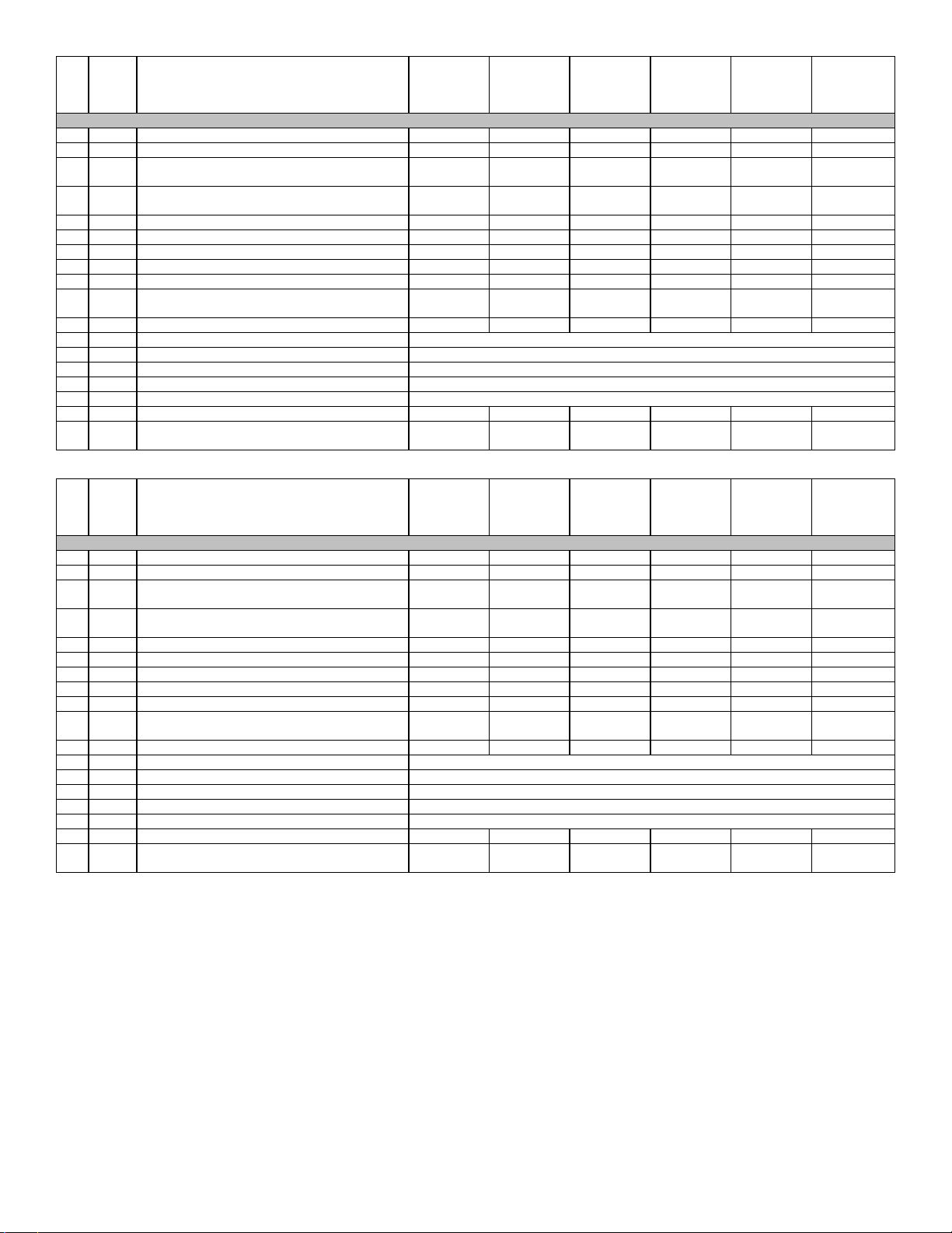
MODEL
No. Notes
Note: 024, 030, and 036 units produced on or before approximately F3806 may have been produced with a different motor, capacitor, and fan blade
combination than shown below. If replacing any of these components on older units, all three components must be changed in accordance with those
listed below. Failure to do so may affect motor reliability and increase fan noise.
46 Stk Fan Motor 51-100998-24 51-102728-14 51-100998-24 51-100998-24 51-100998-19 51-100998-19
47 Stk Fan Blade 70-101323-19 70-23594-03 70-101323-19 70-101323-19 70-23594-02 70-23594-02
78 Capacitor - Compressor/Fan See Compressor Group
No. Notes
Note: 024, 030, and 036 units produced on or before approximately F3806 may have been produced with a different motor, capacitor, and fan blade
combination than shown below. If replacing any of these components on older units, all three components must be changed in accordance with those
listed below. Failure to do so may affect motor reliability and increase fan noise.
46 Stk Fan Motor 51-100998-24 51-100998-19 51-100998-19
47 Stk Fan Blade 70-101323-19 70-23594-02 70-23594-02
78 Stk Capacitor - Fan Motor 43-100496-04 43-100496-09 43-100496-09
No. Notes
38 Blower Relay See Electrical Group
Stk Blower Assembly (Includes items 51-56) AS-58662-31 AS-58662-31 AS-58662-32 AS-58662-33 AS-58662-34 AS-58662-35
51 Housing AS-58619-01 AS-58619-01 AS-58619-02 AS-58619-02 AS-58619-02 AS-58619-02
52 Stk Blower Wheel 70-20218-01 70-20218-01 70-18625-03 70-18625-03 70-18625-03 70-18625-03
53 Cut-Off AE-64401-10 AE-64401-10 AE-64401-06 AE-64401-06 AE-64401-06 AE-64401-06
54 Stk Blower Motor 51-101879-05 51-101879-05 51-101880-12 51-101880-13 51-101920-12 51-101920-13
Motor Mounting Bracket Assembly (Includes items 55, 56) AS-53148-03 AS-53148-03 N/A N/A N/A N/A
55 Motor Band 70-19927-01 70-19927-01 70-19927-03 70-19927-03 70-19927-03 70-19927-03
56 Motor Arm Assembly (3) 70-19929-02 70-19929-02 70-19929-09 70-19929-09 70-19929-09 70-19929-09
No. Notes
38 Blower Relay See Electrical Group
Stk Blower Assembly (Includes items 51-56) AS-58662-33 AS-58662-34 AS-58662-35
51 Housing AS-58619-02 AS-58619-02 AS-58619-02
52 Stk Blower Wheel 70-18625-03 70-18625-03 70-18625-03
53 Cut-Off AE-64401-06 AE-64401-06 AE-64401-06
54 Stk Blower Motor 51-101880-13 51-101920-12 51-101920-13
55 Motor Band 70-19927-03 70-19927-03 70-19927-03
56 Motor Arm Assembly (3) 70-19929-09 70-19929-09 70-19929-09
TECHNICALVARIATION
COOLING CAPACITY
ELECTRICAL DESIGNATION
MODEL
TECHNICALVARIATION
COOLING CAPACITY
ELECTRICAL DESIGNATION
MODEL
TECHNICALVARIATION
COOLING CAPACITY
ELECTRICAL DESIGNATION
MODEL
TECHNICALVARIATION
COOLING CAPACITY
ELECTRICAL DESIGNATION
RQPW
B
024
J
FANGROUP
RQPW
B
036
C
FANGROUP
RQPW
B
024
J
BLOWER GROUP
RQPW
B
036
C
BLOWER GROUP
RQPW
B
025
J
RQPW
B
042
C
RQPW
B
025
J
RQPW
B
042
C
RQPW
B
030
J
RQPW
B
048
C
RQPW
B
030
J
RQPW
B
048
C
RQPW
B
036
J
RQPW
B
036
J
RQPW
B
042
J
RQPW
B
042
J
RQPW
B
048
J
RQPW
B
048
J
Page 6 of 21
13-January-2016
92-42800-RQPW-B
Page 7
No. Notes
CONDENSER COIL:
61 Stk Condenser Coil AS-102015-03 AS-102015-03 AS-102016-03 AS-102017-03 AS-102014-03 AS-102014-03
Distributor Assembly 83-101782-01 83-101782-01 83-101782-02 83-101782-02 83-101782-03 83-101782-03
Access ValveBody 61-18542-01 61-18542-01 61-18542-01 61-18542-01 61-18542-01 61-18542-01
Access ValveCore 61-18551-01 61-18551-01 61-18551-01 61-18551-01 61-18551-01 61-18551-01
EVAPORATOR COIL:
62 Stk Evaporator Coil w/Drain Pan AS-102660-05 AS-102660-05 AS-102660-06 AS-102660-06 AS-102660-07 AS-102660-07
62 Stk Evaporator Coil w/Drain Pan (Tin Plated) AS-104668-05 AS-104668-05 AS-104668-06 AS-104668-06 AS-104668-07 AS-104668-07
63 Drain Pan Grommet 56-23601-01 56-23601-01 56-23601-01 56-23601-01 56-23601-01 56-23601-01
64 Stk Drain Pan - Before F4507 AS-58607-32 N/A AS-58607-32 AS-58607-32 AS-58607-32 AS-58607-32
64 Stk Drain Pan - After F4507 68-23602-02 68-23602-02 68-23602-02 68-23602-02 68-23602-02 68-23602-02
64a Drain Trap- (Attached to Drain Pan) 68-23603-01 68-23603-01 68-23603-01 68-23603-01 68-23603-01 68-23603-01
65 Auxiliary Drain Pipe AE-58611-01 AE-58611-01 AE-58611-01 AE-58611-01 AE-58611-01 AE-58611-01
66 Stk TXV 61-102211-06 61-102211-29 61-102211-07 61-102211-07 61-102211-08 61-102211-08
67 Condensate Shield AE-101751-01 AE-101751-01 AE-101751-02 AE-101751-02 AE-101751-02 AE-101751-02
68 Condensate Barrier AE-100544-01 AE-100544-01 AE-100544-02 AE-100544-02 AE-100544-02 AE-100544-02
69 Distributor Assembly 83-102202-01 83-102202-01 83-102202-02 83-102202-02 83-102202-03 83-102202-03
REFRIGERATION GROUP:
71 Stk Charge Compensator N/A N/A N/A 83-25361-02 83-25361-06 83-25361-12
72 Stk,3 Reversing Valve w/Coil - See Note 3 61-102498-09 61-102498-09 61-102498-09 61-102498-09 61-102498-09 61-101684-06
Stk Solenoid Coil - ReversingValve 61-101713-01 61-101713-01 61-101713-01 61-101713-01 61-101713-01 61-101713-01
Wiring Harness - ReversingValve 61-26149-01 61-26149-01 61-26149-01 61-26149-01 61-26149-01 61-26149-01
73 TXV Bulb Strap Kit 64-101357-01 64-101357-01 64-101357-01 64-101357-01 64-101357-01 64-101357-01
74 Bulb Strainer 83-26020-02 83-26020-02 83-26020-02 83-26020-02 83-26020-02 83-26020-02
75 Filter Drier 83-41714-03 83-41714-03 83-41714-03 83-41714-03 83-41714-01 83-41714-01
No. Notes
Compressor ID: 7491 8181 7492 7493 7494 7495
76 Stk Compressor
77 Grommet (4) 56-18518-04 56-18518-04 56-18518-04 56-18518-04 56-18518-06 56-18518-06
Stk Compressor Wiring Harness (Molded Plug) 45-100834-80 45-100834-80 45-100834-80 45-100834-80 45-100834-80 45-100834-80
Stk
78 Stk Capacitor - Compressor/Fan 43-26271-09 43-101666-24 43-26271-09 43-26271-41 43-101665-42 43-101665-47
No. Notes
Compressor ID: 7576 7577 7578
76 Stk Compressor
77 Grommet (4) 56-18518-04 56-18518-04 56-18518-04
Stk Compressor Wiring Harness (Molded Plug) 45-100834-80 45-100834-80 45-100834-80
Stk
MODEL
TECHNICALVARIATION
COOLING CAPACITY
MODEL
TECHNICALVARIATION
COOLING CAPACITY
ELECTRICAL DESIGNATION
Low Pressure Control - After Approximate Date Code
F3710
MODEL
TECHNICALVARIATION
COOLING CAPACITY
ELECTRICAL DESIGNATION
Low Pressure Control - After Approximate Date Code
F3710
RQPW
B
024
COIL GROUP
RQPW
B
024
J
COMPRESSOR GROUP
55-102045-01S55-102045-01S55-102045-02S55-102045-03S55-102045-06
47-102240-02 47-102240-02 47-102240-02 47-102240-02 47-102240-02 47-102240-02
RQPW
B
036
C
COMPRESSOR GROUP
55-102045-05S55-102045-08S55-102045-11
47-102240-02 47-102240-02 N/A
RQPW
B
025
RQPW
B
025
J
RQPW
B
042
C
RQPW
B
030
RQPW
B
030
J
RQPW
B
048
C
S
RQPW
B
036
RQPW
B
036
J
RQPW
B
042
RQPW
B
042
J
S
RQPW
B
048
RQPW
B
048
J
55-102045-09S
Page 7 of 21
13-January-2016
92-42800-RQPW-B
Page 8

No. Notes
81 Stk Heat Exchanger (Includes Center Panel and Turbulators) AS-58632-01 AS-58632-02 AS-58632-03 AS-58632-04
82 Turbulators
Collector Box Gasket 68-23644-01 68-23644-01 68-23644-01 68-23644-01
83 Collector Box AE-58588-01 AE-58588-01 AE-58588-01 AE-58588-01
84 Stk Limit Control - Blower Shelf
84 Stk Limit Control - Blower Shelf
84 Stk Limit Control - Blower Shelf
85 NOX Insert Assembly
86 Lower Burner Shield (NOX) AE-59148-01 AE-59148-01 AE-59148-01 AE-59148-01
87 Radiation Shield AE-58595-01 AE-58595-01 AE-58595-01 AE-58595-01
88 Stk,4
88 Stk,4
89 Stk,4
89 Stk,4
90 4
90 4
91 4
91 4
97 4 Bushing - After approximate Date Code F3708 (See Note 4) 45-42519-01 45-42519-01 45-42519-01 45-42519-01
Stk,2,4 One-piece Burner Retrofit Kit - See Note 2 AS-60993-82 AS-60993-83 AS-60993-84 AS-60993-85
92 Manifold Assembly 81-101154-01 81-101154-01 81-101154-01 81-101154-01
94 Square Head Plug (Used on Manifold to plug extra holes)
93 Burner Orifice - Natural Gas See Orifice Selection Chart
93 Burner Orifice - LP See Orifice Selection Chart
93 Number of Orifices (2) (3) (4) (5)
95 Stk Flame Sensor 62-23543-02 62-23543-02 62-23543-02 62-23543-02
96 Stk Ignition Electrode/Cable Assembly 62-23556-01 62-23556-01 62-23556-01 62-23556-01
MODEL
TECHNICALVARIATION
HEATING CAPACITY
HEAT EXCHANGER, BURNER / MANIFOLD
Limit - Manual Reset (Burner Compartment) - Before approximate Date
Code F3708 (See Note 4)
Limit - Manual Reset (Burner Compartment) - After approximate Date
Code F3708 (See Note 4)
Burner Tube w/Shield (Inshot) - Before approximate Date Code F3708
(See Note 4)
Burner Assembly (One-piece) - After approximate Date Code F3708
(See Note 4)
Burner Support Bracket (2) - Before approximate Date Code F3708
(See Note 4)
Burner Support Bracket (2) - After approximate Date Code F3708 (See
Note 4)
Burner Support - (Holds Burners between Burner Support Brackets) Before approximate Date Code F3708 (See Note 4)
Burner Support - (Holds Burners between Burner Support Brackets) After approximate Date Code F3708 (See Note 4)
RQPW
B
04
AE-58591-02
(2)
47-23610-11
(All except 025))
47-102436-02
(025)
75-23684-01
(2)
47-100241-01 47-100241-01 47-100241-01 47-100241-01
47-22861-02 47-22861-02 47-22861-02 47-22861-02
75-22840-02
(2)
AS-60993-02 AS-60993-03 AS-60993-04 AS-60993-05
AE-61588-01 AE-61588-01 AE-61588-01 AE-61588-01
AE-61588-02 AE-61588-02 AE-61588-02 AE-61588-02
AE-58592-02 AE-58592-02 AE-58592-02 AE-58592-02
AE-102438-01 AE-102438-01 AE-102438-01 AE-102438-01
81-23593-01
(3)
RQPW
B
06
AE-58591-02
(3)
47-23610-05
(024)
47-23610-03
(030-048)
47-102436-01
(025)
75-23684-01
(3)
75-22840-02
(3)
81-23593-01
(2)
RQPW
B
08
AE-58591-02
(4)
47-23610-03
(All except 025)
47-102436-01
(025)
75-23684-01
(4)
75-22840-02
(4)
81-23593-01
(1)
RQPW
B
10
AE-58591-02
(5)
47-23610-01
(All)
75-23684-01
(5)
75-22840-02
(5)
N/A
Page 8 of 21
13-January-2016
92-42800-RQPW-B
Page 9

No. Notes
39 Stk Integrated Furnace Control Board (IFC) 62-23599-02 62-23599-02 62-23599-02 62-23599-02 62-23599-04
Stk Gas Valve - Natural Gas 60-105055-01 60-23490-03 60-23490-01 60-24290-01 60-105055-01
Stk,1 Gas Valve - LP See Note 1 See Note 1 See Note 1 See Note 1 See Note 1
Stk LP Conversion Kit EP-85H EP-84W EP-84W EP-84W EP-85H
No. Notes
39 Stk Integrated Furnace Control Board (IFC) 62-23599-04
Stk Gas Valve - Natural Gas 60-105055-01
Stk,1 Gas Valve - LP See Note 1
Stk LP Conversion Kit EP-85H
No. Notes
Economizer - Downflow, 3 Position RXRE-CAA30
Economizer - Downflow, Fully Modulating RXRD-CAM10
Economizer - Horizontal Application, Fully Modulating RXRD-CCM10
Fresh Air Damper - Fixed, 35% RXRF-FAA1
Fresh Air Damper - Motorized, 35% RXRF-FAB1
Filter Kit RXRY-B01
Low Ambient Control RXPZ-G01
High Pressure Control RXAB-D01
Canadian High Altitude Kit (for Natural Gas Only) RXRX-AH01
MODEL
TECHNICALVARIATION
GAS CODE
GAS CONTROLS
MODEL
TECHNICALVARIATION
GAS CODE
GAS CONTROLS
MODEL
SIZE
OPTIONS AND ACCESSORIES
RQPW
B
1R
RQPW
B
2U
RQPW
ALL
RQPW
B
1S
RQPW
B
1X
RQPW
B
2A
RQPW
B
2G
Page 9 of 21
13-January-2016
92-42800-RQPW-B
Page 10

CAUTION: Selection of the correct Natural Gas Orifice requires the following information for the specific installation:
1) Furnace Input Rating (BTU/HR)
2) Number of Burners
2) Altitude (ft.)
For detailed information and instructions for Orifice selection, see the Gas Furnace LP Conversion Kit Index 92-21519-47 and the latest edition of the
National Fuel Gas Code Handbook, or the National Standard of Canada, Natural Gas and Propane Installation Code, CAN B149.1.
CAUTION:This information is provided for replacement purposes only. Conversion for operation at High Altitude must be done using the kit specified
on the product specification sheet for the unit.
NOTE:This Orifice sizing chart is based on a Natural Gas heating value of 1075 BTU/cu. ft and a pressure setting of 3.5 in. water column.
NOTE: Factory installed orifices are calculated and sized based on a Natural Gas heating value of 1075 BTU/cu. ft. and an elevation of 0 - 2000 ft.
Furnace
Input
Rating (BTU/HR)
40,000 36,000 2 62-22175-45 62-22175-47 62-22175-48 62-22175-49 62-22175-45 62-22175-15
60,000 54,000 3 62-22175-45 62-22175-47 62-22175-48 62-22175-49 62-22175-45 62-22175-15
72,000 N/A 4 62-22175-15 62-22175-49 62-22175-50 62-22175-51 62-22175-15 N/A
80,000 72,000 4 62-22175-45 62-22175-47 62-22175-48 62-22175-49 62-22175-45 62-22175-15
90,000 N/A 5 62-22175-15 62-22175-49 62-22175-50 62-22175-51 62-22175-15 N/A
100,000 90,000 5 62-22175-45 62-22175-47 62-22175-48 62-22175-49 62-22175-45 62-22175-15
120,000 108,000 6 62-22175-45 62-22175-47 62-22175-48 62-22175-49 62-22175-45 62-22175-15
135,000 121,500 6 62-22175-44 62-22175-45 62-22175-47 62-22175-48 62-22175-44 62-22175-45
150,000 135,000 6 62-22175-42 62-22175-43 62-22175-44 62-22175-45 62-22175-42 62-22175-44
180,000 N/A 9 62-22175-45 62-22175-47 62-22175-48 62-22175-49 62-22175-45 N/A
210,000 N/A 9 62-22175-43 62-22175-44 62-22175-45 62-22175-47 62-22175-43 N/A
210,000 N/A 10 62-22175-45 62-22175-47 62-22175-48 62-22175-49 62-22175-45 N/A
225,000 202,500 9 62-22175-42 62-22175-43 62-22175-44 62-22175-45 62-22175-42 62-22175-44
250,000 225,000 10 62-22175-42 62-22175-43 62-22175-44 62-22175-45 62-22175-42 62-22175-44
252,000 225,000 9 62-22175-40 62-22175-42 62-22175-43 62-22175-44 62-22175-40 62-22175-42
252,000 N/A 12 62-22175-45 62-22175-47 62-22175-48 62-22175-49 62-22175-45 N/A
290,000 N/A 14 62-22175-45 62-22175-47 62-22175-48 62-22175-49 62-22175-45 N/A
300,000 270,000 12 62-22175-42 62-22175-43 62-22175-44 62-22175-45 62-22175-42 62-22175-44
330,000 N/A 14 62-22175-43 62-22175-44 62-22175-45 62-22175-47 62-22175-43 N/A
350,000 315,000 14 62-22175-42 62-22175-43 62-22175-44 62-22175-45 62-22175-42 62-22175-44
400,000 360,000 14 62-22175-40 62-22175-42 62-22175-43 62-22175-44 62-22175-40 62-22175-42
CAUTION: Selection of the correct LP Orifice requires the following information for the specific installation:
1) Furnace Input Rating (BTU/HR)
2) Number of Burners
2) Altitude (ft.)
For detailed information and instructions for Orifice selection, see the Gas Furnace LP Conversion Kit Index 92-21519-47 and the latest edition of the
National Fuel Gas Code Handbook, or the National Standard of Canada, Natural Gas and Propane Installation Code, CAN B149.1.
CAUTION:This information is provided for replacement purposes only. Conversion to LP or for operation at High Altitude should be done using the
kit(s) specified on the product specification sheet for the unit.
NOTE:This Orifice sizing chart is developed using the specified pressure setting of 10 in. water column instead of the 11.0 in water column used by the NFG and
CANB149.1.
NOTE: Orifices supplied in the LP Conversion Kit are calculated and sized based on a heating value of 2500 BTU/cu. ft. and an elevation of 0 - 2000 ft.
Furnace
Input
Rating (BTU/HR)
40,000 36,000 2 62-22175-55 62-22175-55 62-22175-56 62-22175-56 62-22175-55 62-22175-13
60,000 54,000 3 62-22175-55 62-22175-55 62-22175-56 62-22175-56 62-22175-55 62-22175-13
72,000 N/A 4 62-22175-13 62-22175-57 62-22175-57 62-22175-59 62-22175-13 N/A
80,000 72,000 4 62-22175-55 62-22175-55 62-22175-56 62-22175-56 62-22175-55 62-22175-13
90,000 N/A 5 62-22175-13 62-22175-57 62-22175-57 62-22175-59 62-22175-13 N/A
100,000 90,000 5 62-22175-55 62-22175-55 62-22175-56 62-22175-56 62-22175-55 62-22175-13
120,000 108,000 6 62-22175-55 62-22175-55 62-22175-56 62-22175-56 62-22175-55 62-22175-13
135,000 121,500 6 62-22175-54 62-22175-55 62-22175-55 62-22175-56 62-22175-54 62-22175-55
150,000 135,000 6 62-22175-54 62-22175-55 62-22175-55 62-22175-56 62-22175-54 62-22175-54
180,000 N/A 9 62-22175-55 62-22175-55 62-22175-56 62-22175-56 62-22175-55 N/A
210,000 N/A 9 62-22175-54 62-22175-55 62-22175-55 62-22175-56 62-22175-54 N/A
210,000 N/A 10 62-22175-55 62-22175-55 62-22175-56 62-22175-56 62-22175-55 N/A
225,000 202,500 9 62-22175-54 62-22175-55 62-22175-55 62-22175-56 62-22175-54 62-22175-54
250,000 225,000 10 62-22175-54 62-22175-55 62-22175-55 62-22175-56 62-22175-54 62-22175-54
252,000 225,000 9 62-22175-53 62-22175-54 62-22175-54 62-22175-55 62-22175-53 62-22175-54
252,000 N/A 12 62-22175-55 62-22175-55 62-22175-56 62-22175-56 62-22175-55 N/A
290,000 N/A 14 62-22175-55 62-22175-55 62-22175-56 62-22175-56 62-22175-55 N/A
300,000 270,000 12 62-22175-54 62-22175-55 62-22175-55 62-22175-56 62-22175-54 62-22175-54
330,000 N/A 14 62-22175-54 62-22175-55 62-22175-55 62-22175-56 62-22175-54 N/A
350,000 315,000 14 62-22175-54 62-22175-55 62-22175-55 62-22175-56 62-22175-54 62-22175-54
400,000 360,000 14 62-22175-53 62-22175-54 62-22175-54 62-22175-55 62-22175-53 62-22175-54
Canadian High
Altitude Derated
Input
(BTU/HR)
Canadian High
Altitude Derated
Input
(BTU/HR)
PACKAGE EQUIPMENT - ORIFICE SELECTION CHART - NATURAL GAS
Number
of
Burners
PACKAGE EQUIPMENT - ORIFICE SELECTION CHART - LP
Number
of
Burners
0 - 2000
U.S.
0 - 2000
U.S.
2001 - 4000
U.S.
2001 - 4000
U.S.
Elevation (ft.)
4001 - 6000
U.S.
Elevation (ft.)
4001 - 6000
U.S.
Country
8000+
U.S.
Country
8000+
U.S.
0 - 2000
Canada
0 - 2000
Canada
2001 - 4500
Canada
2001 - 4500
Canada
13-January-2016
92-42800-RQPW-B
Page 10 of 21
Page 11

Exploded View
Page 11 of 21
13-January-2016
92-42800-RQPW-B
Page 12

Control Access Panel Detail
Page 12 of 21
13-January-2016
92-42800-RQPW-B
Page 13

Control Box Assembly
Page 13 of 21
13-January-2016
92-42800-RQPW-B
Page 14

Blower Assembly
Page 14 of 21
13-January-2016
92-42800-RQPW-B
Page 15

EvaporatorCoil Assembly
Page 15 of 21
13-January-2016
92-42800-RQPW-B
Page 16

Condenser Coil
Page 16 of 21
13-January-2016
92-42800-RQPW-B
Page 17

Compressor and Refrigeration Components
Page 17 of 21
13-January-2016
92-42800-RQPW-B
Page 18

Heat Exchanger Assembly
Page 18 of 21
13-January-2016
92-42800-RQPW-B
Page 19

Burner Assembly (Inshot - Before Approx F3708)
Page 19 of 21
13-January-2016
92-42800-RQPW-B
Page 20

Burner Assembly (One-piece - After Approx F3708)
Page 20 of 21
13-January-2016
92-42800-RQPW-B
Page 21

NOTES
Stk It is recommended that stock be maintained for this part.
N/A Not Applicable
1 Order GasValve for Natural Gas along with LP Conversion Kit.
2 This kit includes all necessary items to retrofit units using individual burner tubes with the later one-piece burner
design.
3 The reversing valve specified for 024, 025, 030, 036, 042, 048 models may be different than the one originally
supplied with the equipment. The use of the specified valve is recommended forimproved shifting performance.
4 The date code shown is approximate. It should be confirmed by the servicing technician as to whether the unit was
manufactrured using the later one-piece burner design or the earlier inshot individual burner tubes. Components
are NOT interchangeable.
5 The rectangle-shaped defrost control board used in later production models may be retrofitted in place of the
square shaped board used in earlier production. The later defrost board includes support for high and low
refrigerant pressure controls and also includes a 30 second compressor delay for noise abatement during defrost.
If the unit does not include pressure controls, jumpers will need to be field supplied for these terminals.
DISCLAIMER: This document is intended to provide general replacement parts information to aid qualified
service personnel in the repair of these models. The complete Model and Serial Number of the unit under repair
should be specified when selecting and ordering replacement parts. Specifications and illustrations are subject
to change without notice. Document 92-42800-RQPW-B supersedes all previous parts lists for these models. See
http://www.rheempartslists.net/92-42800-RQPW-B for the latest revision of this document. The manufacturer
assumes no obligation for errors or omissions. Service personnel must verify the proper and safe operation of
equipment after the replacement of any original components.
P.O. Box 17010
Fort Smith, AR 72917-7010
 Loading...