

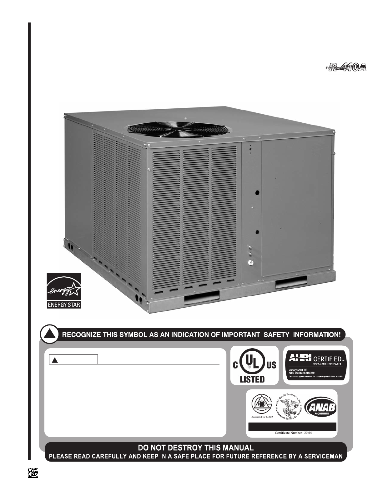
Rheem RQNL, RQPL Installation Manual
INSTALLATION INSTRUCTIONS
!
THESE INSTRUCTIONS ARE INTENDED AS AN AID TO
QUALIFIED, LICENSED SERVICE PERSONNEL FOR
PROPER INSTALLATION, ADJUSTMENT AND OPERATION
OF THIS UNIT. READ THESE INSTRUCTIONS THOROUGHLY
BEFORE ATTEMPTING INSTALLATION OR OPERATION.
FAILURE TO FOLLOW THESE INSTRUCTIONS MAY RESULT
IN IMPROPER INSTALLATION, ADJUSTMENT, SERVICE OR
MAINTENANCE POSSIBLY RESULTING IN FIRE, ELECTRICAL
SHOCK, PROPERTY DAMAGE, PERSONAL INJURY OR DEATH.
WARNING
!
ISO 9001:2008
PACKAGE HEAT PUMPS FEATURING
INDUSTRY STANDARD R-410A REFRIGERANT
RQNL- 13 SEER SERIES (2-4 TONS)
RQPL- 14 SEER SERIES (2-4 TONS)
14 SEER ONLY
SUPERSEDES 92-20522-42-07
92-20522-42-08

TABLE OF CONTENTS
I. Safety Information.................................................................................................3
II. Introduction ...........................................................................................................5
A. R-410A Refrigerant...........................................................................................5
1. Specification of R-410A.................................................................................5
2. Quick Reference for R-410A.........................................................................5
3. Evaporator Coil/TXV .....................................................................................5
4. Tools Required for Installing and Servicing R-410A Models.........................5
III. Checking Product Received..................................................................................8
IV. Equipment Protection............................................................................................8
V. Installation.............................................................................................................8
A. General .............................................................................................................8
1. Pre-Installation Check Points........................................................................8
2. Location.........................................................................................................8
B. Outside Slab Installation..................................................................................10
C.Clearances ......................................................................................................10
D.Rooftop Installation..........................................................................................10
VI. Ductwork.............................................................................................................11
VII. Filters ..................................................................................................................12
VIII. Conversion Procedure ........................................................................................13
IX. Condensate Drain...............................................................................................13
X. Condensate Drain, Outdoor Coil.........................................................................14
XI. Electrical Wiring ..................................................................................................14
A. Power Wiring...................................................................................................14
B. Control Wiring .................................................................................................14
C.Internal Wiring.................................................................................................14
D.Grounding .......................................................................................................14
E. Thermostat......................................................................................................15
XII. Indoor Air Flow Data ...........................................................................................16
XIII. Crankcase Heat ..................................................................................................16
XIV. Pre-Start Check...................................................................................................16
XV. Startup.................................................................................................................16
XVI. Operation ............................................................................................................17
XVII. Auxiliary Heat......................................................................................................17
XVIII. Demand Defrost Control and High/Low Pressure Controls.................................18
XIX. General Data..................................................................................................20-24
XX. Miscellaneous
Electrical Data ................................................................................................25-26
Airflow Performance.......................................................................................27-30
Heater Kit Characteristics...............................................................................31-32
Wiring Diagrams.............................................................................................33-37
Charge Charts................................................................................................38-42
Trouble Shooting .................................................................................................43
2
I. SAFETY INFORMATION
WARNING
!
IMPORTANT: ALL MANUFACTURER PRODUCTS MEET CURRENT FEDERAL
OSHA GUIDELINES FOR SAFETY. CALIFORNIA PROPOSITION 65 WARNINGS
ARE REQUIRED FOR CERTAIN PRODUCTS, WHICH ARE NOT COVERED BY
THE OSHA STANDARDS.
CALIFORNIA'S PROPOSITION 65 REQUIRES WARNINGS FOR PRODUCTS
SOLD IN CALIFORNIA THAT CONTAIN, OR PRODUCE, ANY OF OVER 600 LISTED CHEMICALS KNOWN TO THE STATE OF CALIFORNIA TO CAUSE CANCER
OR BIRTH DEFECTS SUCH AS FIBERGLASS INSULATION, LEAD IN BRASS,
AND COMBUSTION PRODUCTS FROM NATURAL GAS.
ALL “NEW EQUIPMENT” SHIPPED FOR SALE IN CALIFORNIA WILL HAVE
LABELS STATING THAT THE PRODUCT CONTAINS AND/OR PRODUCES
PROPOSITION 65 CHEMICALS. ALTHOUGH WE HAVE NOT CHANGED OUR
PROCESSES, HAVING THE SAME LABEL ON ALL OUR PRODUCTS FACILITATES MANUFACTURING AND SHIPPING. WE CANNOT ALWAYS KNOW
“WHEN, OR IF” PRODUCTS WILL BE SOLD IN THE CALIFORNIA MARKET.
YOU MAY RECEIVE INQUIRIES FROM CUSTOMERS ABOUT CHEMICALS
FOUND IN, OR PRODUCED BY, SOME OF OUR HEATING AND AIR-CONDITIONING EQUIPMENT, OR FOUND IN NATURAL GAS USED WITH SOME OF OUR
PRODUCTS. LISTED BELOW ARE THOSE CHEMICALS AND SUBSTANCES
COMMONLY ASSOCIATED WITH SIMILAR EQUIPMENT IN OUR INDUSTRY AND
OTHER MANUFACTURERS.
• GLASS WOOL (FIBERGLASS) INSULATION
• CARBON MONOXIDE (CO)
• FORMALDEHYDE
• BENZENE
MORE DETAILS ARE AVAILABLE AT THE WEBSITES FOR OSHA
(OCCUPATIONAL SAFETY AND HEALTH ADMINISTRATION), AT
WWW.OSHA.GOV
ENVIRONMENTAL HEALTH HAZARD ASSESSMENT), AT WWW.OEHHA.ORG.
CONSUMER EDUCATION IS IMPORTANT SINCE THE CHEMICALS AND SUBSTANCES ON THE LIST ARE FOUND IN OUR DAILY LIVES. MOST CONSUMERS ARE AWARE THAT PRODUCTS PRESENT SAFETY AND HEALTH
RISKS, WHEN IMPROPERLY USED, HANDLED AND MAINTAINED.
AND THE STATE OF CALIFORNIA'S OEHHA (OFFICE OF
WARNING
!
THE MANUFACTURER’S WARRANTY DOES NOT COVER ANY DAMAGE OR
DEFECT TO THE HEAT PUMP CAUSED BY THE ATTACHMENT OR USE OF ANY
COMPONENTS, ACCESSORIES OR DEVICES (OTHER THAN THOSE AUTHORIZED BY THE MANUFACTURER) INTO, ONTO OR IN CONJUNCTION WITH
THE HEAT PUMP. YOU SHOULD BE AWARE THAT THE USE OF UNAUTHORIZED COMPONENTS, ACCESSORIES OR DEVICES MAY ADVERSELY AFFECT
THE OPERATION OF THE HEAT PUMP AND MAY ALSO ENDANGER LIFE AND
PROPERTY. THE MANUFACTURER DISCLAIMS ANY RESPONSIBILITY FOR
SUCH LOSS OR INJURY RESULTING FROM THE USE OF SUCH UNAUTHORIZED COMPONENTS, ACCESSORIES OR DEVICES.
WARNING
!
DISCONNECT ALL POWER TO THE UNIT BEFORE STARTING MAINTENANCE.
FAILURE TO DO SO CAN RESULT IN SEVERE ELECTRICAL SHOCK OR DEATH.
WARNING
!
DO NOT, UNDER ANY CIRCUMSTANCES, CONNECT RETURN DUCTWORK
TO ANY OTHER HEAT PRODUCING DEVICE SUCH AS A FIREPLACE INSERT,
STOVE, ETC. UNAUTHORIZED USE OF SUCH DEVICES MAY RESULT IN FIRE,
CA RB ON MONOXIDE P OISONING, EX PL OSION, PRO PE RT Y DAMAGE,
3
WARNING
!
THE UNIT MUST BE PERMANENTLY GROUNDED. A GROUNDING LUG IS
PROVIDED IN THE ELECTRIC HEAT KIT FOR A GROUND WIRE. (SEE FIGURE
10.) FAILURE TO GROUND THIS UNIT CAN RESULT IN FIRE OR ELECTRICAL
SHOCK CAUSING PROPERTY DAMAGE, SEVERE PERSONAL INJURY OR
WARNING
!
ONLY ELECTRIC HEATER KITS SUPPLIED BY THIS MANUFACTURER AS
DESCRIBED IN THIS PUBLICATION HAVE BEEN DESIGNED, TESTED, AND
EVALUATED BY A NATIONALLY RECOGNIZED SAFETY TESTING AGENCY
FOR USE WITH THIS UNIT. USE OF ANY OTHER MANUFACTURED ELECTRIC
HEATERS INSTALLED WITHIN THIS UNIT MAY CAUSE HAZARDOUS CONDITIONS RES ULTING IN PROPER TY D AMAGE, FIRE, BODILY INJURY OR
DEATH.
4
Recognize this symbol as an indica-
!
tion of Important Safety Information!
WARNING
!
IMPORTANT: ALL MANUFACTURER PRODUCTS MEET CURRENT
FEDERAL OSHA GUIDELINES FOR
SAFETY. CALIFORNIA
PROPOSITION 65 WARNINGS ARE
REQUIRED FOR CERTAIN PRODUCTS, WHICH ARE NOT COVERED
BY THE OSHA STANDARDS.
CALIFORNIA'S PROPOSITION 65
REQUIRES WARNINGS FOR PRODUCTS SOLD IN CALIFORNIA THAT
CONTAIN, OR PRODUCE, ANY OF
OVER 600 LISTED CHEMICALS
KNOWN TO THE STATE OF
CALIFORNIA TO CAUSE CANCER
OR BIRTH DEFECTS SUCH AS
FIBERGLASS INSULATION, LEAD
IN BRASS, AND COMBUSTION
PRODUCTS FROM NATURAL GAS.
ALL “NEW EQUIPMENT” SHIPPED
FOR SALE IN CALIFORNIA WILL
HAVE LABELS STATING THAT THE
PRODUCT CONTAINS AND/OR
PRODUCES PROPOSITION 65
CHEMICALS. ALTHOUGH WE HAVE
NOT CHANGED OUR PROCESSES,
HAVING THE SAME LABEL ON ALL
OUR PRODUCTS FACILITATES
MANUFACTURING AND SHIPPING.
WE CANNOT ALWAYS KNOW
“WHEN, OR IF” PRODUCTS WILL
BE SOLD IN THE CALIFORNIA
MARKET.
YOU MAY RECEIVE INQUIRIES
FROM CUSTOMERS ABOUT CHEMICALS FOUND IN, OR PRODUCED
BY, SOME OF OUR HEATING AND
AIR-CONDITIONING EQUIPMENT,
OR FOUND IN NATURAL GAS USED
WITH SOME OF OUR PRODUCTS.
LISTED BELOW ARE THOSE CHEMICALS AND SUBSTANCES COMMONLY ASSOCIATED WITH SIMILAR EQUIPMENT IN OUR INDUSTRY AND OTHER MANUFACTURERS.
• GLASS WOOL (FIBERGLASS)
INSULATION
• CARBON MONOXIDE (CO)
• FORMALDEHYDE
• BENZENE
MORE DETAILS ARE AVAILABLE
AT THE WEBSITES FOR OSHA
(OCCUPATIONAL SAFETY AND
HEALTH ADMINISTRATION), AT
WWW.OSHA.GOV
OF CALIFORNIA'S OEHHA (OFFICE
OF ENVIRONMENTAL HEALTH
HAZARD ASSESSMENT), AT
WWW.OEHHA.ORG. CONSUMER
EDUCATION IS IMPORTANT SINCE
THE CHEMICALS AND SUBSTANCES ON THE LIST ARE
FOUND IN OUR DAILY LIVES. MOST
CONSUMERS ARE AWARE THAT
PRODUCTS PRESENT SAFETY AND
HEALTH RISKS, WHEN IMPROPERLY USED, HANDLED AND MAINTAINED.
AND THE STATE
II. INTRODUCTION
This booklet contains the installation and operating instructions for your package heat
pump. There are a few precautions that should be taken to derive maximum satisfaction
from it. Improper installation can result in unsatisfactory operation or dangerous conditions.
Read this booklet and any instructions packaged with separate equipment required to
make up the system prior to installation. Give this booklet to the owner and explain its provisions. The owner should retain this booklet for future reference.
NOTE: A load calculation must be performed to properly determine the required heating
and cooling for the structure. Also, the duct must be properly designed and installed for
proper airflow. Existing ductwork must be inspected for proper size and sealed system.
Proper airflow is necessary for both user comfort and equipment performance.
IMPORTANT: Proper application, installation and maintenance of this equipment is a must
if consumers are to receive the full benefit for which they have paid.
A. R-410A REFRIGERANT
All units are factory charged with R-410A refrigerant.
1. Specification of R-410A:
Application: R-410A is not a drop-in replacement for R-22; equipment designs must
accommodate its higher pressures. It cannot be retrofitted into R-22 units.
Pressure: The pressure of R-410A is approximately 60% (1.6 times) greater than R-
22. Recovery and recycle equipment, pumps, hoses and the like need to have design
pressure ratings appropriate for R-410A. Manifold sets need to range up to 800 psig
high-side and 250 psig low-side with a 550 psig low-side retard. Hoses need to have a
service pressure rating of 800 psig. Recovery cylinders need to have a 400 psig service
pressure rating. DOT 4BA400 or DOT BW400.
Combustibility: At pressures above 1 atmosphere, mixture of R-410A and air can
become combustible. R-410A and air should never be mixed in tanks or supply
lines, or be allowed to accumulate in storage tanks. Leak checking should never
be done with a mixture of R-410A and air. Leak checking can be performed safely
with nitrogen or a mixture of R-410A and nitrogen.
2. Quick Reference Guide For R-410A
• R-410A refrigerant operates at approximately 60% higher pressure (1.6 times) than R-
22. Ensure that servicing equipment is designed to operate with R-410A.
• R-410A refrigerant cylinders are pink.
• R-410A, as with other HFC’s is only compatible with POE oils.
• Vacuum pumps will not remove moisture from POE oil.
• R-410A systems are to be charged with liquid refrigerants. Prior to March 1999, R410A refrigerant cylinders had a dip tube. These cylinders should be kept upright for
equipment charging. Post March 1999 cylinders do not have a dip tube and should
be inverted to ensure liquid charging of the equipment.
• Do not install a suction line filter drier in the liquid line.
• A liquid line filter drier is standard on every unit.
• Desiccant (drying agent) must be compatible for POE oils and R-410A
3. Evaporator Coil / TXV
The thermostatic expansion valve is specifically designed to operate with R-410A. DO
NOT use an R-22 TXV. The existing evaporator must be replaced with the factory
specified TXV evaporator specifically designed for R-410A.
4. Tools Required For Installing & Servicing R-410A Models
Manifold Sets:
-Up to 800 PSIG High side
-Up to 250 PSIG Low Side
-550 PSIG Low Side Retard
Manifold Hoses:
-Service Pressure Rating of 800 PSIG
Recovery Cylinders:
-400 PSIG Pressure Rating
-Dept. of Transportation 4BA400 or BW400
!
CAUTION
R-410A systems operate at higher pressures than R-22 systems. Do not use
R-22 service equipment or components on R-410A equipment.
5
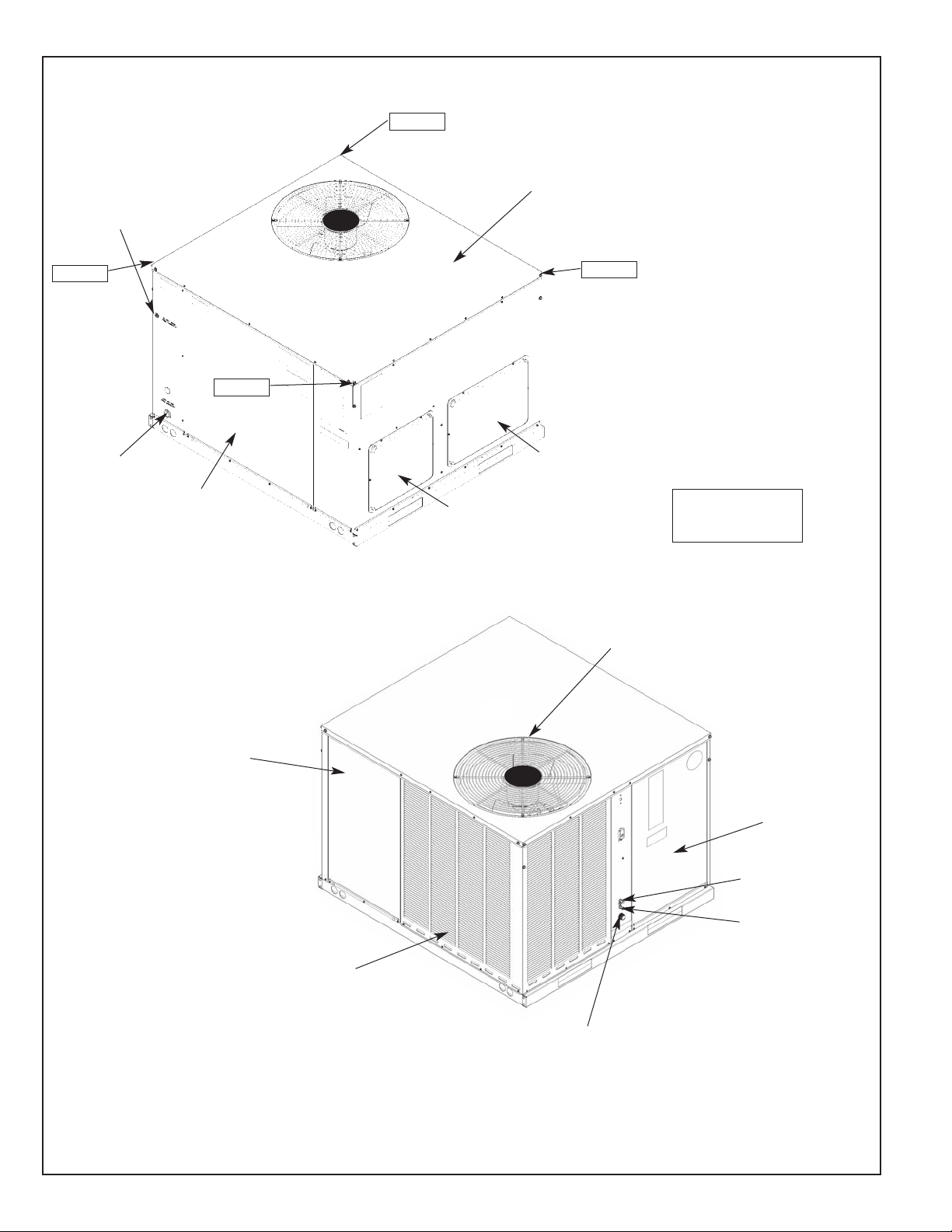
FIGURE 1
THERMOSTAT
WIRE
ENTRANCE
29% ± 2%
30% ± 2%
TOP COVER
21% ± 2%
20% ± 2%
ELECTRICAL
POWER
ENTRANCE
BLOWER/
EVAPORATOR
ACCESS PANEL
FILTER ACCESS
PANEL (FOR
UNIT MOUNTED
FILTER ACCESSORY)
SIDE SUPPLY
DUCT OPENING
SIDE RETURN
DUCT OPENING
CORNER WEIGHTS %
OF TOTAL UNIT
WEIGHT
OUTDOOR FAN GRILLE
AND COMPRESSOR ACCESS
LIQUID PRESSURE
SERVICE PORT
CONTROL
ACCESS PANEL
SUCTION PRESSURE
SERVICE PORT
OUTDOOR COIL
PROTECTIVE GRILLE
THREADED PVC CONDENSATE
DRAIN CONNECTION (3/4 N.P.T.)
6
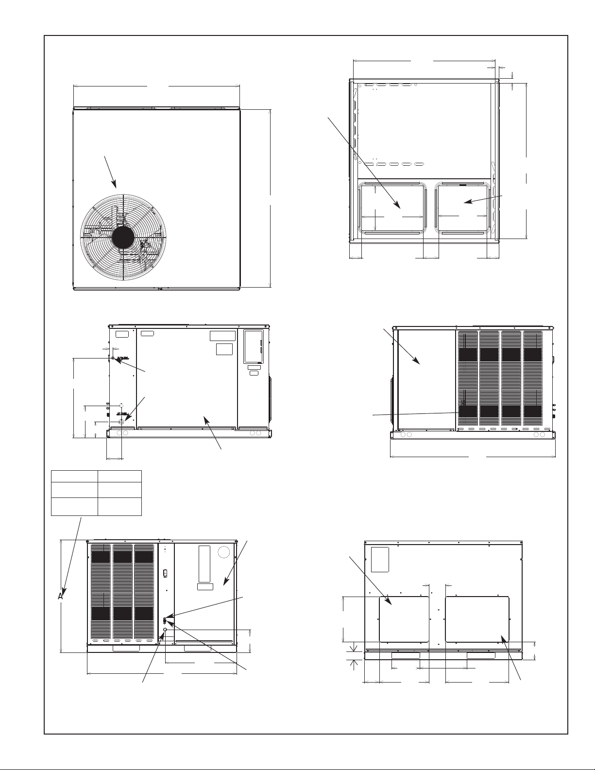
FIGURE 1
OUTDOOR
FAN GRILLE
AND
COMPRESSOR
ACCESS
4719⁄32
ⴖ
451⁄16
INSIDE
ⴖ
BOTTOM
13⁄16
TYP.
ⴖ
ⴖ
11⁄2
TYP.
RETURN
DUCT
OPENING
ⴖ
497⁄16
INSIDE
BOTTOM
5013⁄16
ⴖ
ⴖ
141⁄4
TYP.
199⁄16
ⴖ
ⴖ
153⁄8
SUPPLY DUCT
OPENING
ⴖ
11⁄8
ⴖ
255⁄16
ⴖ
103⁄16
51⁄16ⴖ
Model # Height “A”
B024, B025
B030, B036
B042, B048
35
5
41"
THREADED PVC
CONDENSATED DRAIN
CONNECTION (3/4 N.P.T.)
THERMOSTAT
WIRE
ENTRANCE
ELECTRICAL POWER
ENTRANCE
ⴖ
43⁄4
⁄16"
FRONT VIEW
471⁄2
SIDE VIEW
2211⁄16
ⴖ
BLOWER/
EVAPORATOR
ACCESS
PANEL
PRESSURE
75⁄16
ⴖ
CONTROL
ACCESS
PANEL
LIQUID
SERVICE
PORT
ⴖ
SUCTION
PRESSURE
SERVICE
PORT
ⴖ
313⁄16
FILTER ACCESS
45⁄16
ⴖ
33⁄16
ⴖ
SIDE VIEW
PANEL (FOR
UNIT MOUNTED
FILTER
ACCESSORY)
OUTDOOR
COIL
PROTECTIVE
GRILLE
ⴖ
527⁄16
IMPORTANT:
INSTALLATION MUST NOT INTERFERE WITH DRAINAGE OPENINGS
IN BOTTOM OF UNIT UNDER OUTDOOR COIL.
REAR VIEW
SIDE SUPPLY
DUCT
OPENING
ⴖ
47⁄8
ⴖ
133⁄4
TYP.
21⁄2
ⴖ
ⴖ
47⁄16
SHOWN WITH DUCT COVERS REMOVED.
81⁄2
TYP.
ⴖ
ⴖ
15
191⁄8
143⁄16
TYP.
ⴖ
ⴖ
57⁄16ⴖ
SIDE RETURN
DUCT
OPENING
7
WARNING
!
THE MANUFACTURER’S WARRANTY DOES NOT COVER ANY DAMAGE OR DEFECT TO THE HEAT
PUMP CAUSED BY THE ATTACHMENT OR USE OF ANY COMPONENTS, ACCESSORIES OR
DEVICES (OTHER THAN THOSE
AUTHORIZED BY THE MANUFACTURER) INTO, ONTO OR IN CONJUNCTION WITH THE HEAT PUMP.
YOU SHOULD BE AWARE THAT
THE USE OF UNAUTHORIZED
COMPONENTS, ACCESSORIES OR
DEVICES MAY ADVERSELY
AFFECT THE OPERATION OF THE
HEAT PUMP AND MAY ALSO
ENDANGER LIFE AND PROPERTY.
THE MANUFACTURER DISCLAIMS
ANY RESPONSIBILITY FOR SUCH
LOSS OR INJURY RESULTING
FROM THE USE OF SUCH UNAUTHORIZED COMPONENTS, ACCESSORIES OR DEVICES.
III. CHECKING PRODUCT RECEIVED
Upon receiving the unit, inspect it for any damage from shipment. Claims for damage,
either shipping or concealed, should be filed immediately with the shipping company.
Check the unit model number, heating size, electrical characteristics, and accessories to
determine if they are correct.
IV. EQUIPMENT PROTECTION FROM THE
ENVIRONMENT
The metal parts of this unit may be subject to rust or deterioration in adverse environmental conditions. This oxidation could shorten the equipment’s useful life. Salt spray, fog or
mist in seacoast areas, sulphur or chlorine from lawn watering systems, and various chemical contaminants from industries such as paper mills and petroleum refineries are especially corrosive.
If the unit is to be installed in an area where contaminants are likely to be a problem, special attention should be given to the equipment location and exposure.
1. Avoid having lawn sprinkler heads spray direction on the unit cabinet.
2. In coastal areas, locate the unit on the side of the building away from the waterfront.
3. Shielding provided by a fence or shrubs may give some protection.
4. Elevating the unit off its slab or base enough to allow air circulation will help avoid
holding water against the basepan.
Regular maintenance will reduce the buildup of contaminents and help to protect
the unit’s finish.
WARNING
!
DISCONNECT ALL POWER TO THE UNIT BEFORE STARTING MAINTENANCE.
FAILURE TO DO SO CAN RESULT IN SEVERE ELECTRICAL SHOCK OR DEATH.
1. Frequent washing of the cabinet, fan blade and coil with fresh water will remove most
of the salt or other contaminants that build up on the unit.
2. Regular cleaning and waxing of the cabinet with an automobile polish will provide
some protection.
3. A liquid cleaner may be used several times a year to remove matter that will not wash
off with water.
Several different types of protective coatings are offered in some areas. These coatings
may provide some benefit, but the effectiveness of such coating materials cannot be verified by the equipment manufacturer.
The best protection is frequent cleaning, maintenance and minimal exposure to
contaminants.
V. INSTALLATION
A. GENERAL
1. PRE-INSTALLATION CHECK-POINTS
Before attempting any installation, the following points should be carefully considered:
a. Structural strength of supporting members.
(rooftop installation)
b. Clearances and provision for servicing.
c. Power supply and wiring.
d. Air duct connections.
e. Drain facilities and connections.
f. Location for minimum noise.
2. LOCATION
These units are designed for outdoor installations. They can be mounted on a
slab or rooftop. They are not to be installed within any part of a structure such as
an attic, crawl space, closet, or any other place where condenser air flow is
restricted or other than outdoor ambient conditions prevail. Since the application
8
FIGURE 2
PACKAGE HEAT PUMP
OUTSIDE SLAB INSTALLATION, BASEMENT OR
CRAWL SPACE DISTRIBUTION SYSTEM
60ⴖ OVERHEAD
CLEARANCE
12ⴖ CLEARANCE
WITHOUT
ECONOMIZER
24ⴖ CLEARANCE
WITH
ECONOMIZER
FIGURE 3
PACKAGE HEAT PUMP
OUTSIDE SLAB INSTALLATION, CLOSET DISTRIBUTION
FILTER
GRILL
BRANCH
CIRCUIT
DISCONNECT
SERVICE
ACCESS PANELS
DO NOT BLOCK
ACCESS
SUPPLY DUCT AT
CLOSET CEILING
SLAB
FLOOR
36ⴖ
24ⴖ TO SERVICE
BLOWER & EVAPORATOR
0ⴖ MIN.
CLEARANCE
0 ⴖ CLEARANCE AROUND
SUPPLY DUCT TO
COMBUSTIBLE STRUCTURE
FIGURE 4
PACKAGE HEAT PUMP
RIGGING FOR LIFTING
I268
IMPORTANT: UNIT MUST BE LEVEL
TO PREVENT WATER MIGRATION
RIGGING
NOT
PROVIDED
POWER
SUPPLY
CONDUIT
THERMOSTAT
WIRE CONDUIT
I267
DETAIL A
SEE DETAIL A
ST-A1100-01
9

of the units is of the outdoor type, it is important to consult your local code authorities at the time the first installation is made.
B. OUTSIDE SLAB INSTALLATION (Typical outdoor slab installations are shown
in Figures 2 and 3.)
1. Select a location where external water drainage cannot collect around the unit.
2. Provide a level concrete slab extending a minimum 3" beyond all four sides of the
unit. The slab should be sufficient above grade to prevent ground water from
entering the unit. IMPORTANT: To prevent transmission of noise or vibration,
slab should not be connected to building structure.
3. The location of the unit should be such as to provide proper access for inspection
and servicing.
4. Locate unit where operating sounds will not disturb owner or neighbors.
5. Locate unit so roof runoff water does not pour directly on the unit. Provide gutter
or other shielding at roof level. Do not locate unit in an area where excessive
snow drifting may occur or accumulate.
6. It is essential that the unit be elevated above the base pad to allow for condensate drainage and possible refreezing of condensation. Provide a base pad which
is slightly pitched away from the structure. Route condensate off base pad to an
area which will not become slippery and result in personal injury. IMPORTANT:
Do not interfere with openings in bottom of unit.
7. Where snowfall is anticipated, the height of the unit above the ground level must
be considered. Mount unit high enough to be above average area snowfall and to
allow for proper condensate drainage. IMPORTANT: Do not interfere with open-
ings in bottom of unit.
C. CLEARANCES
The following minimum clearances must be observed for proper unit performance
and serviceability.
1. Provide 36" minimum clearance at the front and right side of the unit for service
access. Provide 12" minimum clearance on the left side of the unit for air inlet.
2. Provide 60" minimum clearance between top of unit and maximum 3 foot overhang.
3. Unit is design certified for application on combustible flooring with 0" minimum
clearance.
4. See Figure 2 for illustration of minimum installation-service clearances.
D. ROOFTOP INSTALLATION
1. Before locating the unit on the roof, make sure that the strength of the roof and
beams is adequate at that point to support the weight involved. (See specification
sheet for weight of unit.) This is very important and user’s responsibility.
2. For rigging and roofcurb details, see Figures 4 and 5. Use accessory lift brackets
and field-furnished spreaders.
3. For roofcurb assembly, see Roofcurb Installation Instructions.
4. If the roofcurb is not used, provisions for disposing of condensate water runoff
during defrosting must be provided.
5. The unit should be placed on a solid and level roofcurb or platform of adequate
strength. IMPORTANT: Do not interfere with opening in bottom of unit. (See
Figures 6 and 7.)
6. The location of the unit on the roof should be such as to provide proper access for
inspection and servicing.
IMPORTANT: If unit will not be put into service immediately, cover supply and return
openings to prevent excessive condensation.
10
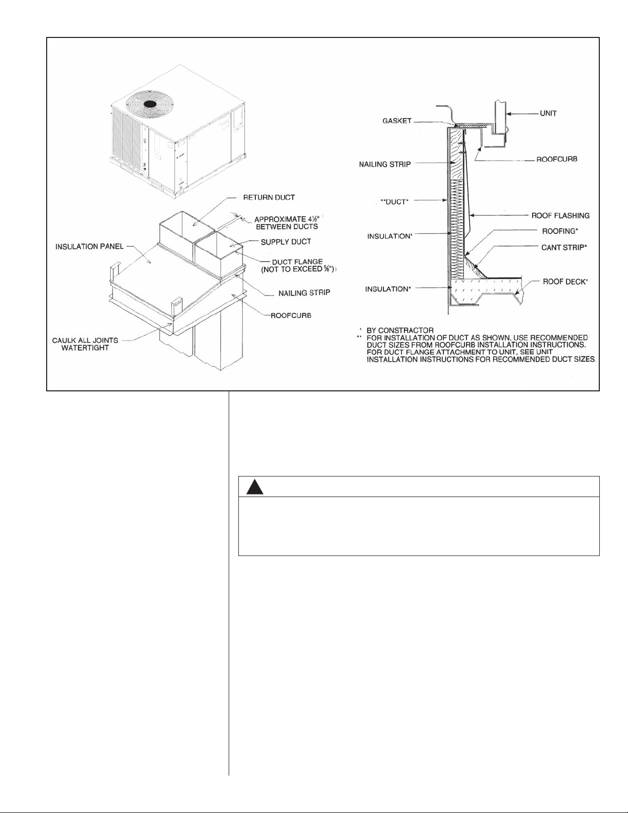
FIGURE 5
PACKAGE HEAT PUMP
ROOFCURB INSTALLATION
I270 I271
VI. DUCTWORK
Ductwork should be fabricated by the installing contractor in accordance with local
codes, state codes and NFPA90A. Industry manuals may be used as a guide when sizing and designing the duct system - contact Air Conditioning Contractors of America,
1513 16th St. N.W., Washington, D.C. 20036.
WARNING
!
DO NOT, UNDER ANY CIRCUMSTANCES, CONNECT RETURN DUCTWORK
TO ANY OTHER HEAT PRODUCING DEVICE SUCH AS A FIREPLACE INSERT,
STOVE, ETC. UNAUTHORIZED USE OF SUCH DEVICES MAY RESULT IN FIRE,
CA RB ON MONOXIDE P OISONING, EX PL OSION, PRO PE RT Y DAMAGE,
Place the unit as close to the space to be air conditioned as possible allowing clearance
dimensions as indicated. Run ducts as directly as possible to supply and return outlets.
Use of non-flammable waterproof flexible connectors on both supply and return connections at the unit to reduce noise transmission is recommended.
It is preferable to install the unit on the roof of the structure if the registers or diffusers
are located on the wall or in the ceiling. Consider a slab installation when the registers
are low on a wall or in the floor.
On ductwork exposed to outside air conditions of temperature and humidity, use a minimum of 2" of insulation and a vapor barrier. Distribution system in attic, furred space or
crawl space should be insulated with at least 2" of insulation with vapor barrier. One-half
to 1" thickness of insulation is usually sufficient for ductwork inside the air conditioned
space.
Provide balancing dampers for each branch duct in the supply system. Properly support
the ductwork from the structure.
When installing ductwork use noncombustible flexible connectors between ductwork and
unit to reduce noise and vibration transmission into the ductwork.
11
FIGURE 6
PACKAGE HEAT PUMP
FLAT ROOFTOP INSTALLATION, ATTIC OR DROP CEILING
DISTRIBUTION SYSTEM. MOUNTED ON
ROOFCURB. CURB MUST BE LEVEL
SERVICE ACCESS
PANELS. DO NOT
BLOCK ACCESS
CONDENSATE INTO
ROOFDRAIN IF REQ’D
BY LOCAL CODES.
THERMOSTAT WIRE
CONDUIT
BRANCH CIRCUIT
DISCONNECT
POWER
SUPPLY
CONDUIT
I272
VII. FILTERS
Filters are not provided with this unit. They may be supplied and installed in the return
air duct by the installer. A field installed filter grille is recommended for easy and convenient access to the filters for periodic inspection and cleaning. Filters must have adequate face area for the rated air quantity of the unit. See Airflow Performance Table - or
Electrical and Physical Data Table - for recommended filter size.
However, if an internal filter is required, an optional internal filter kit is available which
will work for downflow or horizontal applications. For installation, see Filter Kit
Installation Instruction.
NOTE: Do not operate the system without filters.
12
FIGURE 7
PACKAGE HEAT PUMP
PITCHED ROOFTOP INSTALLATION, ATTIC
OR DROP CEILING DISTRIBUTING SYSTEM.
MUST BE MOUNTED LEVEL.
CONDENSATE
DRAIN INTO
ROOFDRAIN IF
REQ’D BY LOCAL
CODES.
SERVICE ACCESS
PANELS. DO NOT
BLOCK ACCESS
SUPPLY PLENUM
BRANCH
CIRCUIT
DISCONNECT
POWER SUPPLY
CONDUIT
THERMOSTAT
WIRE
CONDUIT
I273
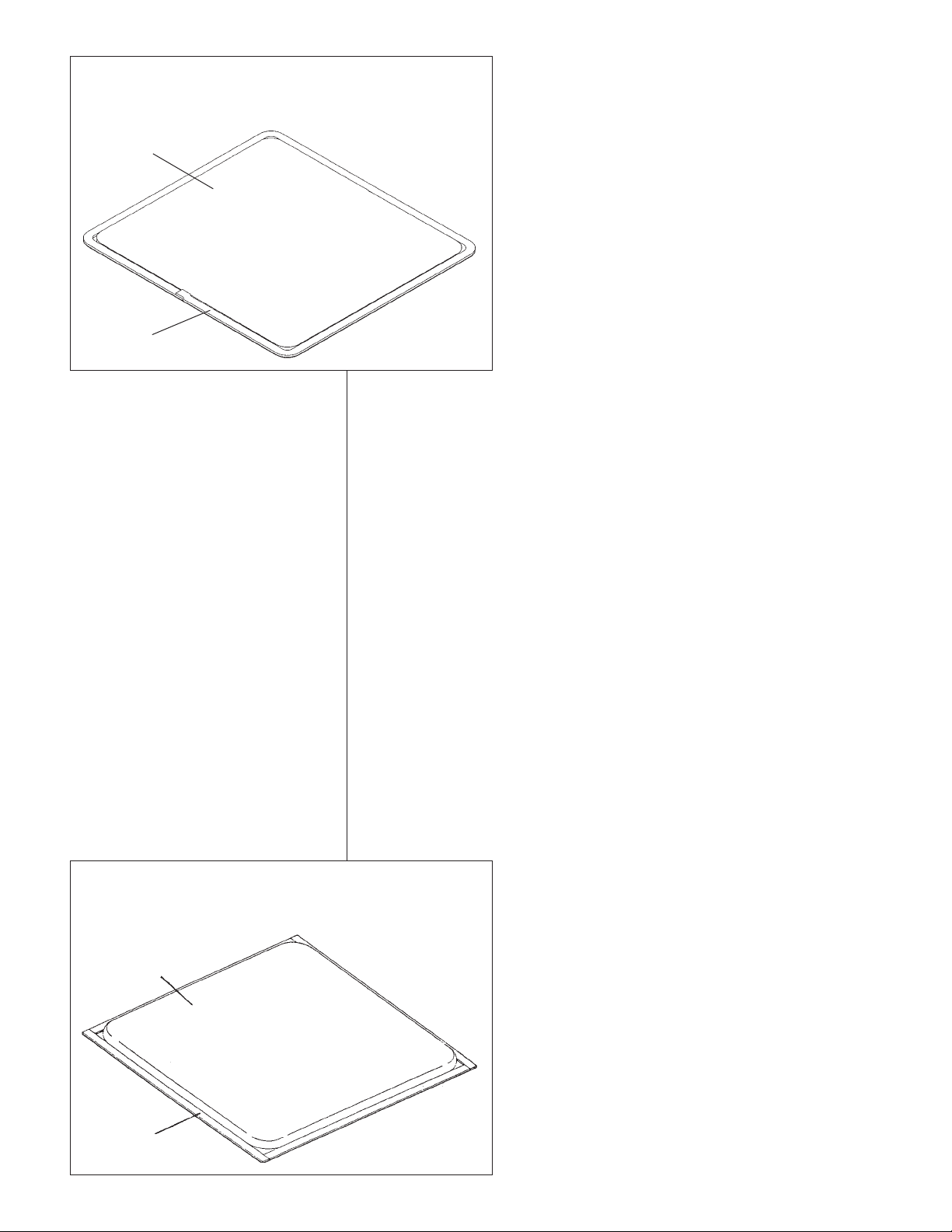
FIGURE 8
COVER GASKET DETAIL
FOR UNITS SHIPPED FOR SIDE DISCHARGE
APPLICATION BEING CONVERTED TO DOWNFLOW
SUPPLY/RETURN
AIR COVER
TAPE
AROUND FLANGE
I654
VIII.CONVERSION PROCEDURE
1. DOWNFLOW TO HORIZONTAL
a. Remove screws and covers from outside of supply and return sections.
b. Install gasket (supplied with parts bag) around perimeter of covers as illustrated in
“Cover Gasket Detail,” Figure 8.
c. Install covers in bottom of unit with insulated side up.
NOTE: Slip back flange of cover under tab on bottom supply duct opening.
d. Secure covers to base of unit with screw engaging prepunched holes in unit base.
2. HORIZONTAL TO DOWNFLOW
a. Remove screws and covers from the downflow supply and return sections. Both
covers are accessible from the inside of the unit.
NOTE: Supply cover must be rotated 90º before it can be removed.
b. Install gasket (supplied with parts bag) around perimeter of cover on the insulated
side. See Figure 9.
c. Install covers on the outside of the unit over the horizontal supply and return
opening using existing screws.
IX. CONDENSATE DRAIN
The indoor coil condensate drain ends with a threaded (3/4" NPT) PVC stub. A trap is
built in for proper condensate drainage and to prevent debris from being drawn into the
unit. Do not connect drain to closed sewer line. It is recommended that a PVC cement not
be used so that the drain line can be easily cleaned in the future.
NOTE: Do not install an external trap.
FIGURE 9
COVER GASKET DETAIL
FOR UNITS SHIPPED FOR DOWNFLOW APPLICATION
BEING CONVERTED TO SIDE DISCHARGE
SUPPLY/RETURN
AIR COVER
TAPE
AROUND FLANGE
13
X. CONDENSATE DRAIN, OUTDOOR COIL
The outdoor coil during heating operation will sweat or run water off. The outdoor coil will
also run water off during the defrost cycle. See Section V, Installation, for mounting precautions.
XI. ELECTRICAL WIRING
Field wiring must comply with the National Electrical Code* state and local ordinances
that may apply.
*C.E.C. in Canada
A. POWER WIRING
1. It is important that proper electrical power is available at the unit. Voltage should
not vary more than 10% from that stamped on the unit rating plate. On three
phase units, phases must be balanced within 3%.
2. Install a branch circuit disconnect within sight of the unit and of adequate size to
handle the starting current.
3. For branch circuit wiring (main power supply to unit disconnect), the minimum
wire size can be determined from the circuit ampacity found on the unit nameplate
or from Table F and the National Electrical Code or Canadian Electrical Code.
4. This unit incorporates single point electrical connection for unit and electric heat
accessory.
5. Power wiring must be run in grounded rain-tight conduit. Connect the power field
wiring as follows:
a. NO ELECTRIC HEAT - Connect the field wires directly to the contactor in the
unit control box. Connect ground wire to ground lug.
b. WITH ELECTRIC HEAT - Connect the field wires to the terminal block on the
electric heater kit. Connect the ground wire to the ground lug on the heater kit.
NOTE: For installation of the heater kit, follow the instructions provided with the
heater kit.
6. The pigtail wires in the electric heat box are factory wired to the contactor in the
control box and are protected by internal fuses in the hinged fuse box mounted
under the control box. See label on fuse box cover for fuse sizing.
7. DO NOT connect aluminum field wires to electric heat kit power input terminals.
B. CONTROL WIRING (Class II)
1. Do not run low voltage wiring in conduit with power wiring.
2. Control wiring is routed through the 7/8" hole approximately 11" from the unit top
in the corner post adjacent to the control box. Use a minimum #18 AWG thermostat wire. For wire lengths exceeding 50', use #16 AWG thermostat wire. The low
voltage wires are connected to the unit pigtails which are supplied with the unit in
the low voltage connection box located below the unit control box. See Figure 10.
3. It is necessary that only heat pump thermostats be used. Please contact your distributor for part number information.
4. Figure 11 shows representative low voltage connection diagrams. Read your thermostat installation instructions for any special requirements for your specific thermostat. These connection diagrams are wired to minimize the amount of auxiliary
electric heaters to be energized during defrost.
NOTE: Units installed in Canada require that an outdoor thermostat (30,000 min.
cycles of endurance) be installed and be wired with C.E.C. Class I wiring.
C. INTERNAL WIRING
1. A diagram of the internal wiring of this unit is located on the electrical control box
cover. If any of the original wire as supplied with the appliance must be replaced,
the wire gauge and insulation must be the same as original wiring.
D. GROUNDING
14
WARNING
!
THE UNIT MUST BE PERMANENTLY GROUNDED. A GROUNDING LUG IS
PROVIDED IN THE ELECTRIC HEAT KIT FOR A GROUND WIRE. (SEE FIGURE
10.) FAILURE TO GROUND THIS UNIT CAN RESULT IN FIRE OR ELECTRICAL
SHOCK CAUSING PROPERTY DAMAGE, SEVERE PERSONAL INJURY OR
DEATH.
 Loading...