

Rheem RKKB SERIES, RKNB SERIES, RKMB SERIES Owner's Manual
FORM NO. R11-836 REV. 3
Supersedes Form No. R11-836 Rev. 2
RKKB- STANDARD EFFICIENCY SERIES
NOMINAL SIZES 15-25 TONS [52.8-87.9 kW]
ASHRAE 90.1-1989 COMPLIANT MODELS
RKMB- HIGH EFFICIENCY SERIES
NOMINAL SIZES 15 & 20 TONS [52.8 & 70.3 kW]
ASHRAE 90.1-1999 COMPLIANT MODELS
RKNB- SUPER HIGH EFFICIENCY SERIES
NOMINAL SIZE 15 TON [52.8 kW]
ENERGYSTAR COMPLIANT MODEL
PACKAGE
GAS / ELECTRIC ROOFTOP UNITS
2
TABLE OF CONTENTS
Unit Features & Benefits ..............................................................................3-6
Selection Procedure ........................................................................................7
Model Identification Options ..........................................................................8-9
General Data
RKKB- Series ......................................................................................10-18
RKMB- Series ......................................................................................19-24
RKNB- Series ......................................................................................25-27
General Data Notes ..................................................................................28
Performance Data
RKKB- Series ......................................................................................29-30
RKMB- Series............................................................................................31
RKNB- Series ............................................................................................32
Airflow Performance
RKKB- Series ......................................................................................33-34
RKMB- Series ......................................................................................33-34
RKNB- Series ............................................................................................33
Electrical Data
RKKB- Series ......................................................................................35-36
RKMB- Series ......................................................................................37-38
RKNB- Series ......................................................................................39-40
Dimensional Data ....................................................................................41-44
Accessories ............................................................................................45-57
Mechanical Specifications ........................................................................58-59
Typical Wiring ..........................................................................................60-65
Limited Warranty ..........................................................................................68
Rheem Package equipment is designed from the ground up with
the latest features and benefits required to compete in today’s
market. The clean design stands alone in the industry and is a
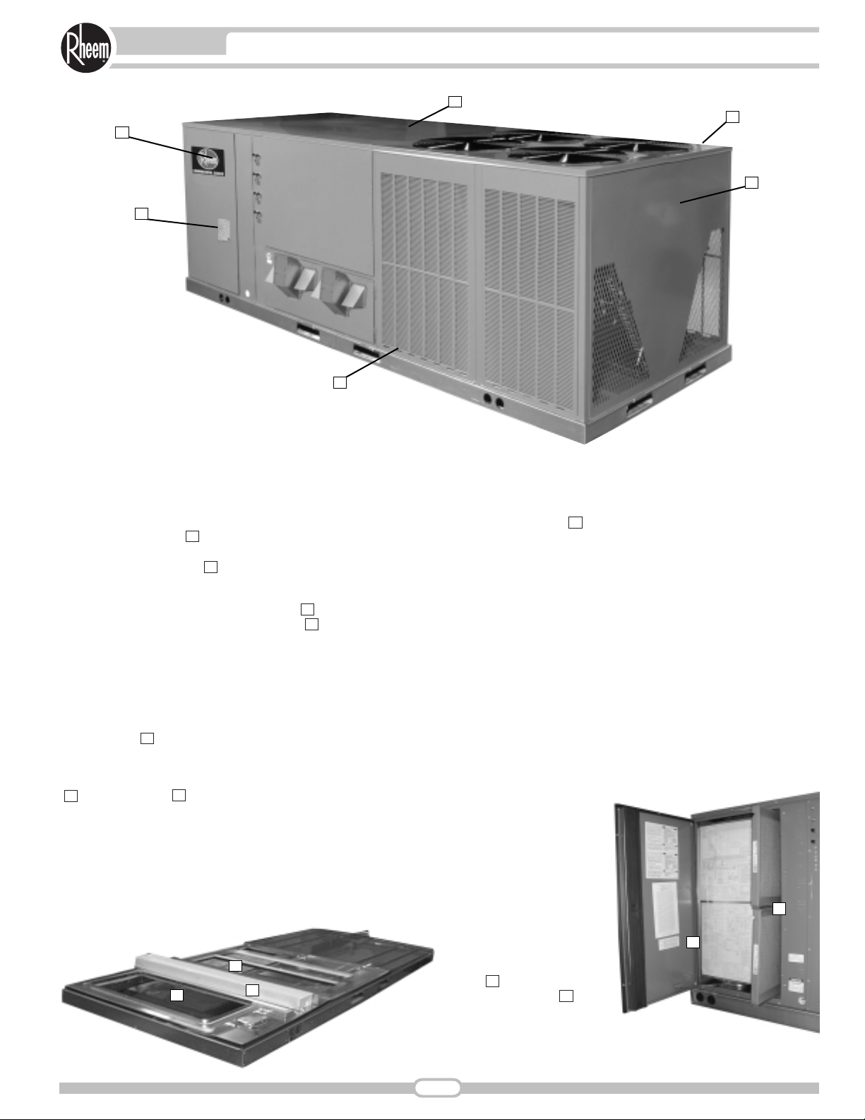
testament to the quality, reliability, ease of installation and serviceability that goes into each unit. Outwardly, the large Rheem Com-
mercial Series
TM
label ( ) identifies the brand to the customer.
The sheet-metal cabinet ( ) uses nothing less than 18-gauge
material for structural components with an underlying coat of
G90. To ensure the leak-proof integrity of these units, the design
utilizes a one-piece top with a 1/8" drip lip ( ), gasket-protected
panels and screws. The Rheem hail guard ( ) is its trademark,
and sets the standard for coil protection in the industry. Every
Rheem package unit uses the toughest finish in the industry,
using electro deposition baked-on enamel tested to withstand a
rigorous 1000-hour salt spray test, per ASTM B117.
Anything built to last must start with the right foundation. In this
case, the foundation is 14-gauge, commercial-grade, full-perimeter base rails ( ), which integrate fork slots and rigging holes to
save set-up time on the job site. The base pan is stamped, which
forms a 1-1/8" flange around the supply and return opening and
has eliminated the worry of water entering the conditioned space
( ). The drainpan ( ) is made of material that resists the
growth of harmful bacteria and is sloped for the latest IAQ benefits. The insulation has been placed on the underside of the
basepan, removing areas that would allow for potential moisture
accumulation, which can facilitate growth of harmful bacteria. All
insulation is secured with both adhesive and mechanical fasteners, and all edges are hidden.
During development, each unit was tested to U.L. 1995, ANSI
21.47, ARI 340-370 and other Rheem-required reliability tests.
Rheem adheres to stringent IS0 9002 quality procedures, and
each unit bears the U.L. and ARI certification labels located on
the unit nameplate ( ). Contractors can rest assured that when
a Rheem package unit arrives at the job, it is ready to go with a
factory charge and quality checks. Each unit also proudly displays the “Made in the USA” designation.
Access to all major compartments is from the front of the unit,
including the filter and electrical compartment, blower compartment, furnace section, and outdoor section. Each panel is permanently embossed with the compartment name (control/filter
access, blower access and furnace access).
Electrical and filter compartment access is through a large, toolless, hinged-access panel. On the outside of the panel is the unit
nameplate, which contains the model and serial number, electrical data and other important unit information.
The unit charging chart is located on the inside of the electrical
and filter compartment door. Electrical wiring diagrams are found
on the control box cover,
which allows contractors
to move them to more
readable locations. To
the right of the control
box the model and serial
number can be found.
Having this information
on the inside will assure
model identification for
the life of the product.
The production line quality test assurance label is
also placed in this location ( ). The two-inch
throwaway filters ( )
are easily removed on a
tracked system for easy
replacement.
10
9
8
7
6
5
4
3
2
1
6
6
7
9
10
2
8
1
4
3
5
3
UNIT FEATURES & BENEFITS—RKKB/RKMB/RKNB- SERIES
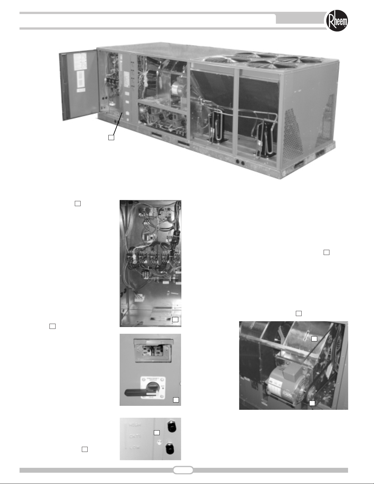
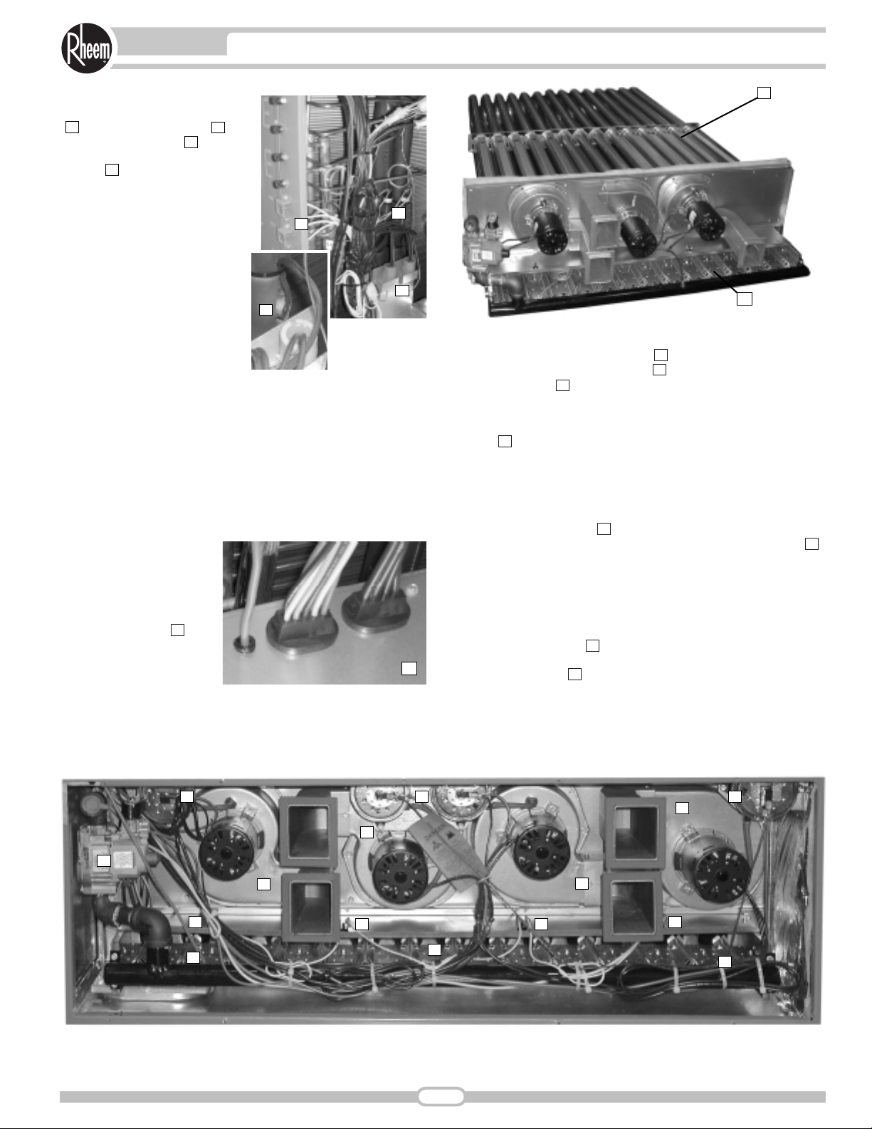
Inside the control box ( ), each electrical component is clearly identified with
a label that matches the component to
the wire diagram for ease of trouble
shooting. All wiring is numbered on
each end of the termination and colorcoded to match the wiring diagram. The
integrated furnace control, used to control furnace operation, incorporates a
flashing LED troubleshooting device.
Flash codes are clearly outlined on the
unit wiring diagram. The control transformer has a low voltage circuit breaker
that trips if a low voltage electrical short
occurs. There is a blower contactor
and compressor contactor for each
compressor.
For added convenience in the field, a
factory-installed convenience outlet and
disconnect ( ) are available. Low and
High voltage can enter either from the
side or through the base. Low-voltage
connections are made through the lowvoltage terminal strip. For ease of
access, the U.L.-required low voltage
barrier can be temporarily removed for
low-voltage termination and then reinstalled. The high-voltage connection is
terminated at the high-voltage terminal
block. The suggested mounting for the
field-installed disconnect is on the exterior side of the electrical control box.
To the right of the electrical and filter
compartment are the externally
mounted gauge ports, which are permanently identified by embossed wording
that clearly identifies the compressor
circuit, high pressure connection and
low pressure connection ( ). With the
gauge ports mounted externally, an
accurate diagnostic of system operation can be performed
quickly and easily.
The blower compartment is to the right of the gauge ports and
can be accessed by removing 5/16" washer-head screws. This
panel is not hinged to assure a water-tight fit with the unit. To
allow easy maintenance of the blower assembly, the entire
assembly easily slides out by removing two 3/8" screws from the
blower retention bracket. The adjustable motor pulley ( ) can
easily be adjusted by loosening the bolts on either side of the
motor mount. Removing the bolts allows for easy removal of the
blower pulley by pushing the blower assembly up to loosen the
belt. Once the belt is removed, the motor sheave can be adjusted
to the desired number of turns, ranging from 0 to 6 turns open.
Where the demands for the job require high static, Rheem has
high-static drives available that deliver nominal airflow up to 2" of
static. By referring to the airflow performance tables listed in the
installation instructions, proper static pressure and CFM requirements can be dialed in. The scroll housing ( ) and blower scroll
provide quiet and
efficient airflow.
The blower
sheave is secured
by an “H” bushing
which firmly
secures the pulley
to the blower shaft
for years of trouble-free operation.
The “H” bushing
allows for easy
removal of the
blower pulley from
the shaft, as
opposed to the
use of a set screw, which can score the shaft, creating burrs that
make blower-pulley removal difficult.
15
14
13
12
11
10
13
11
12
14
15
4
UNIT FEATURES & BENEFITS—RKKB/RKMB/RKNB- SERIES
Also inside the blower compartment is the low-ambient control
( ), low-pressure switch ( ),
high-pressure switch ( ) and
freeze stat refrigerant safety
device ( ). The low-ambient
control allows for operation of the
compressor down to 0 degrees
ambient temperature by cycling
the outdoor fans on high pressure.
The high-pressure switch will
shut off the compressors if
pressures exceeds, 450 PSIG
are detected, this may occur if
the outdoor fan motor fails. The
low-pressure switch shuts off
the compressors if low pressure
is detected due to loss of
charge. The freeze stat protects
the compressor if the evaporator coil gets too cold (below
freezing) due to low airflow. Each factory-installed option is
brazed into the appropriate high or low side and wired appropriately. Use of polarized plugs and sharder fittings allow for easy
field installation.
Inside the blower compartment the interlaced evaporator can
also be viewed. The evaporator uses enhanced fin technology for
maximum heat transfer. The cap-tube metering device assures
even distribution of refrigerant throughout the evaporator.
Wiring throughout the unit
is neatly bundled and
routed. Where wire harnesses go through the
condenser bulkhead or
blower deck, a molded wire
harness assembly ( )
provides an air-tight and
water-tight seal, and provides strain relief. Care is
also taken to tuck raw
edges of insulation behind sheet metal to improve indoor air
quality.
The furnace compartment contains the latest furnace technology
on the market. The draft inducers ( ) draw the flame from the
Rheem exclusive in-shot burners ( ) into the aluminized tubular
heat exchanger ( ) for clean, efficient gas heat. Stainless steel
heat exchangers can be factory installed for those applications
that have high fresh-air requirements, or applications in corrosive
environments. Each furnace is equipment with a two-stage gas
valve ( ), which provides two stages of gas heat input. The first
stage operates at 50% of the second stage (full fire). 81% steady
state efficiency is maintained on both first and second stage by
staging the multiple inducers to optimize the combustion airflow
and maintain a near stioceometric burn at each stage.
The direct spark igniter ( ) assures reliable ignition in the most
adverse conditions. This is coupled with remote flame sense ( )
to assure that the flame has carried across the entire length of
the burner assembly. Gas supply can be routed from the side or
up through the base.
Each furnace has the following safety devices to assure consistent and reliable operation after ignition:
• Pressures switches ( ) to assure adequate combustion airflow
before ignition.
• Rollout switches ( ) to assure no obstruction or cracks in the
heat exchanger.
• A limit device that protects the furnace from over-temperature
problems.
28
27
26
25
24
23
22
21
20
19
18
17
16
18
19
24
21
21
26
27 27 27
25
2828
22
23
22
17
16
20
21
21
2828
5
UNIT FEATURES & BENEFITS—RKKB/RKMB/RKNB- SERIES
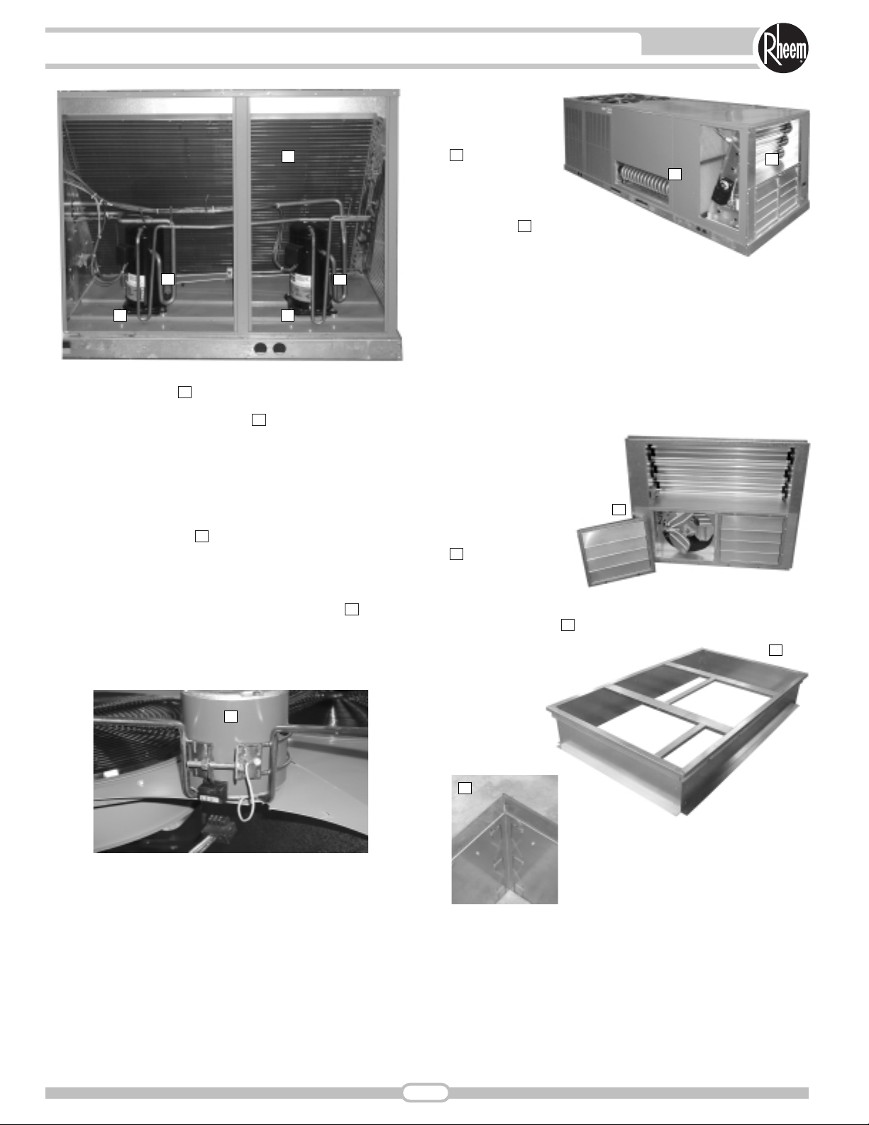
The compressor compartment houses the heartbeat of the unit.
The scroll compressor ( ) is known for its long life, and for
reliable, quiet, and efficient operation. The suction and discharge
lines are designed with shock loops ( ) to absorb the strain and
stress that the starting torque, steady state operation, and shut
down cycle impose on the refrigerant tubing. Each compressor
and circuit is independent for built-in redundancy, and each circuit
is clearly marked throughout the system. Each unit has two
stages of efficient cooling operation, first stage is approximately
50% of second stage.
The condenser fan motor ( ) can easily be accessed and maintained by removing the protective fan grille. The polarized plug
connection allows the motor to be changed quickly and eliminates the need to snake wires through the unit.
The outdoor coil uses the latest enhanced fin design ( ) for the
most effective method of heat transfer. The outdoor coil is protected by louvered panels, which allow unobstructed airflow while
protecting the unit from both Mother Nature and vandalism.
Each unit is
designed for both
downflow or horizontal applications
( ) for job configuration flexibility.
The return air
compartment can
also contain an
economizer ( ). Two
models exits, one for downflow
applications, and one for horizontal
applications. Each unit is pre-wired for the
economizer to allow quick plug-in installation. The
economizer is also available as a factory-installed option. Power
Exhaust is easily field-installed. The economizer, which provides
free cooling when outdoor conditions are suitable and also provides fresh air to meet local requirements, comes standard with
single enthalpy controls. The controls can be upgraded to dual
enthalpy easily in the field. The direct drive actuator combined
with gear drive dampers has eliminated the need for linkage
adjustment in the field. The economizer control has a minimum
position setpoint, an outdoor-air setpoint, a mix-air setpoint, and a
CO
2
setpoint. Barometric
relief is standard on all
economizers. The power
exhaust is housed in the
barometric relief opening
and is easily slipped in with
a plug-in assembly.
The Rheem roofcurb
( ) is made for
toolless assembly at
the jobsite by sequentially engaging the
corner brackets into the
adjacent curb sides ( ), which makes the
assembly process quick and easy.
36
35
34
33
32
31
30
29
29
32
30
29
35
34
34
33
30
36
31
6
UNIT FEATURES & BENEFITS—RKKB/RKMB/RKNB- SERIES

To select an RKKB- Cooling and Heating unit to meet a job
requirement, follow this procedure, with example, using data
supplied in this specification sheet.
1. DETERMINE COOLING AND HEATING REQUIREMENTS
AND SPECIFIC OPERATING CONDITIONS FROM PLANS
AND SPECS.
Example:
Total cooling capacity— 205,000 BTUH [60.1 kW]
Sensible cooling capacity— 155,000 BTUH [45.4 kW]
Heating capacity— 235,000 BTUH [68.9 kW]
*Condenser Entering Air— 95°F [35°C] DB
*Evaporator Mixed Air Entering—65°F [18°C] WB;
78°F [26°C] DB
*Indoor Air Flow (vertical)— 7200 CFM [3398 L/s]
*External Static Pressure— .70 in. WG
2. SELECT UNIT TO MEET COOLING REQUIREMENTS.
Since total cooling is within the range of a nominal 20 ton
[70.3 kW] unit, enter cooling performance table at 95°F [35°C]
DB condenser inlet air. Interpolate between 63°F [2°C] and
67°F [19°C] to determine total and sensible capacity and
power input for 65°F [18°C] WB evap inlet air at 7400 CFM
[1888 L/s] indoor air flow (table basis):
Total Capacity = 232,700 BTUH [68.2 kW]
Sensible Capacity = 186,500 BTUH [54.66 kW]
Power Input (Compressor and Cond. Fans) = 21,600 watts
Use formula in note ➀ to determine sensible capacity at 78°F
[26°C] DB evaporator entering air:
Sensible Capacity = 172,500 BTUH [50.55 kW]
3. CORRECT CAPACITIES OF STEP 2 FOR ACTUAL
AIR FLOW.
Select factors from airflow correction table at 7200 CFM
[3398 L/s] and apply to data obtained in step 2 to obtain
gross capacity:
Total Capacity, 232,700 x .995 = 231,540 BTUH [67.86 kW]
Sensible Capacity, 172,500 x .987 = 170,260 BTUH [49.90 kW]
Power Input 21,600 x .999 = 21,578 Watts
These are Gross Capacities, not corrected for blower motor
heat or power.
4. DETERMINE BLOWER SPEED AND WATTS TO
MEET SYSTEM DESIGN.
Enter Indoor Blower performance table at 7200 CFM
[3398 L/s]. Total ESP (external static pressure) per the spec of
.70 in. includes the system duct and grilles. Add from the table
“Component Air Resistance,” .15 for wet coil, .05 for downflow
air flow, for a total selection static pressure of .900 (.9) inches
of water, and determine:
RPM = 942
WATTS = 4,717
DRIVE = M (standard 7.5 H.P. motor)
5. CALCULATE INDOOR BLOWER BTUH HEAT EFFECT
FROM MOTOR WATTS, STEP 4.
BTUH = 4,717 x 3.412 = 16,094
6. CALCULATE NET COOLING CAPACITIES, EQUAL TO
GROSS CAPACITY, STEP 3, MINUS INDOOR BLOWER
MOTOR HEAT.
Net Total Capacity = 231,540 – 16,094 =
215,446 BTUH [63.14 kW]
Net Sensible Capacity = 170,260 – 16,094 =
154,166 BTUH [45.18 kW]
7. CALCULATE UNIT INPUT AND JOB EER.
Total Power Input = 21,578 (step 3) + 4,717
(step 4) = 26,295 Watts
EER =
Net Total BTUH [kW] (step 6)=215,446
= 8.19
Power Input, Watts (above) 26,295
8. SELECT UNIT HEATING CAPACITY.
From Physical Data Table read that gas heating output
(input rating x efficiency) is:
Heating Capacity = 243,000 BTUH [71.2 kW]
*NOTE: These operating conditions are typical of a commercial applica-
tion in a 95°F/79°F [35°C/26°C] design area with indoor design
of 76°F [24°C] DB and 50% RH and 10% ventilation air, with
the unit roof mounted and centered on the zone it conditions
by ducts.
[ ] Designates Metric Conversions
7
SELECTION PROCEDURE EXAMPLE—RKKB/RKMB/RKNB- SERIES
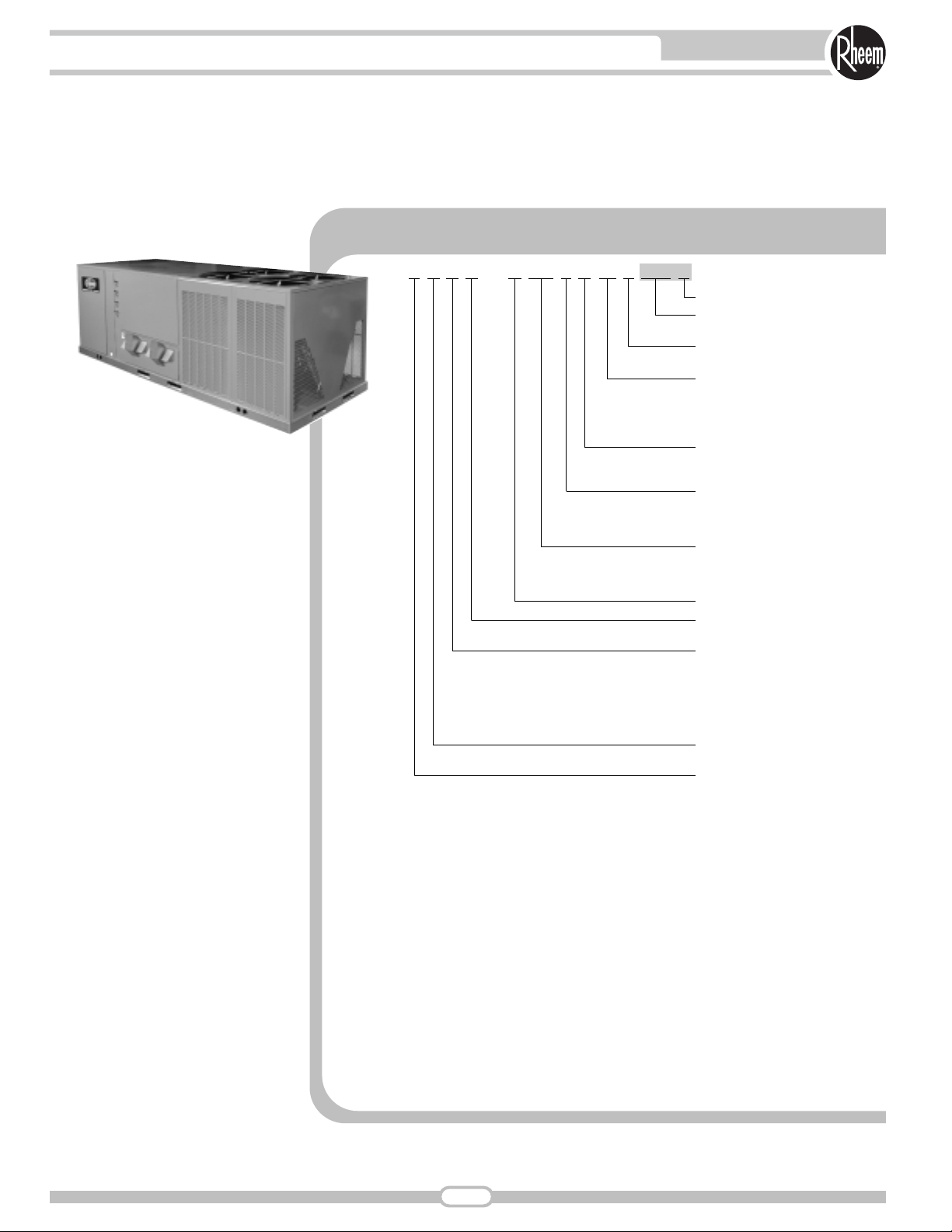
RKKB—A180CL25EXXX
Economizer Option (See Next Page)
Factory Installed Options
(See Next Page)
Ignition System
E = Electric
Heating Capacity (MBH)
25 = 250,000 [73.27] 15 Ton
30 = 300,000 [87.92] 20/25 Ton
35 = 350,000 [102.57] 15 Ton
40 = 400,000 [117.23] 20/25 Ton
Drive Package
L = Belt Drive
M = Belt Drive—High Static
Electrical Designation
C = 208-230 V, 3 PH, 60 Hz
D = 460 V, 3 PH, 60 Hz
Y = 575 V, 3 PH, 60 Hz
Cooling Capacity (BTUH) [kW]
180 = 180,000 [52.75]
240 = 240,000 [70.34]
300 = 300,000 [87.92]
Future Technical Variations
Design Series
B = “B Series Cabinet”
Efficiency Designation
K = Standard Efficiency
ASHRAE 90.1-1989 Compliant
M = High Efficiency
ASHRAE 90.1-1999 Compliant
N = Super High Efficiency
EnergyStar Compliant
Product Classification
K = Rooftop—Commercial
Tradebrand
R = Rheem Packaged Gas/Electric
[ ] Designates Metric Conversions
8
MODEL IDENTIFICATION—RKKB/RKMB/RKNB- SERIES
Option Code
Low Ambient
Time Delay
Freeze Stat
Stainless Steel
Heat Exchanger
AA
Unwired Convenience Outlet
AF x
AH x
BN x x
CL x x x
Unfused Services Discount
PB x x
AJ x
No Options
FACTORY INSTALLED OPTION CODES FOR RKKB, RKMB & RKNB
“x” indicates factory installed option.
ECONOMIZER SELECTION FOR RKKB, RKMB & RKNB
Example: RKKB-A240CL40EXXX (where XX is factory installed option)
Example: No Options
RKKB-A240CL40E
Example: No option with factory installed economizer
RKKB-A240CL40EAAB
Example: Options with low ambient, time delay and freeze stat, unwired convenience outlet, unfused service disconnect, and stainless steel heat exchanger with no factory
installed economizer
RKKB-A240CL40ECLA
Example: Options same as above with factory installed economizer
RKKB-A240CL40ECLB
“x” indicates factory installed option.
Instructions for Factory Installed Option(s) Selection
Note: Three characters following the model number will be utilized to designate a factory-installed option or
combination of options. If no factory option(s) is required, nothing follows the model number.
Step 1. After a basic rooftop model is selected, choose a two-character option code from the FACTORY
INSTALLED OPTION SELECTION TABLE.
Proceed to Step 2.
Step 2. The last option code character is utilized for factory-installed economizers. Choose a character from
the FACTORY INSTALLED ECONOMIZER SELECTION TABLE.
9
OPTIONS—RKKB/RKMB/RKNB- SERIES
No Economizer
A x
B x
Single Enthalpy Economizer
With Barometric Relief

Model RKKB- Series A180CL25E A180CL35E A180CM25E A180CM35E
Cooling Performance
1
Gross Cooling Capacity Btu [kW] 188,000 [55.1] 188,000 [55.1] 188,000 [55.1] 188,000 [55.1]
EER/SEER
2
9/NA 9/NA 9/NA 9/NA
Nominal CFM/ARI Rated CFM [L/s] 6000/6000 [2831/2831] 6000/6000 [2831/2831] 6000/6000 [2831/2831] 6000/6000 [2831/2831]
ARI Net Cooling Capacity Btu [kW] 180,000 [52.7] 180,000 [52.7] 180,000 [52.7] 180,000 [52.7]
Net Sensible Capacity Btu [kW] 134,000 [39.3] 134,000 [39.3] 134,000 [39.3] 134,000 [39.3]
Net System Power kW 20 20 20 20
Heating Performance (Package Gas/Electric)
4
Heating Input Btu [kW] (1st Stage /2nd Stage) 125,000/250,000 [36.6/73.2]175,000/350,000 [51.3/102.6]125,000/250,000 [36.6/73.2]175,000/350,000 [51.3/102.6]
Temperature Rise Range °F [°C] 15-45 [8.3/25] 30-60 [16.7/33.3] 15-45 [8.3/25] 30-60 [16.7/33.3]
Steady State Efficiency (%) 81 81 81 81
Net Weight lbs. [kg] 1790 [812] 1817 [824] 1820 [826] 1847 [838]
No. Burners 10 14 10 14
(3)2x18x24 [51x457x610] (3)2x18x24 [51x457x610] (3)2x18x24 [51x457x610] (3)2x18x24 [51x457x610]
No. Stages 2 2 2 2
Integrated Part Load Value
3
9.9 9.9 9.9 9.9
Heating Output Btu [kW] (1st Stage /2nd Stage) 101,500/203,000 [29.7/59.5] 142,000/284,000 [41.6/83.2] 101,500/203,000 [29.7/59.5] 142,000/284,000 [41.6/83.2]
Compressor
No./Type 4/Scroll 4/Scroll 4/Scroll 4/Scroll
Outdoor Sound Rating (dB)
5
91 91 91 91
Outdoor Coil—Fin Type Louvered Louvered Louvered Louvered
Tube Type Rifled Rifled Rifled Rifled
Tube Size in. [mm] OD 0.375 [9.5] 0.375 [9.5] 0.375 [9.5] 0.375 [9.5]
Face Area sq. ft. [sq. m] 36 [3.34] 36 [3.34] 36 [3.34] 36 [3.34]
Rows / FPI [FPcm] 1 / 22 [9] 1 / 22 [9] 1 / 22 [9] 1 / 22 [9]
Net Latent Capacity Btu [kW] 46,000 [13.5] 46,000 [13.5] 46,000 [13.5] 46,000 [13.5]
Indoor Coil—Fin Type Louvered Louvered Louvered Louvered
Tube Type Rifled Rifled Rifled Rifled
Tube Size in. [mm] 0.375 [9.5] 0.375 [9.5] 0.375 [9.5] 0.375 [9.5]
Face Area sq. ft. [sq. m] 15.75 [1.46] 15.75 [1.46] 15.75 [1.46] 15.75 [1.46]
Rows / FPI [FPcm] 3 / 13 [5] 3 / 13 [5] 3 / 13 [5] 3 / 13 [5]
Refrigerant Control Capillary Tubes Capillary Tubes Capillary Tubes Capillary Tubes
Drain Connection No./Size in. [mm] 1/1 [25.4] 1/1 [25.4] 1/1 [25.4] 1/1 [25.4]
Outdoor Fan—Type Propeller Propeller Propeller Propeller
No. Used/Diameter in. [mm] 4/24 [609.6] 4/24 [609.6] 4/24 [609.6] 4/24 [609.6]
Drive Type/No. Speeds Direct/1 Direct/1 Direct/1 Direct/1
CFM [L/s] 16000 [7550] 16000 [7550] 16000 [7550] 16000 [7550]
No. Motors/HP 4 at 1/3 HP 4 at 1/3 HP 4 at 1/3 HP 4 at 1/3 HP
Motor RPM 1075 1075 1075 1075
Indoor Fan—Type FC Centrifugal FC Centrifugal FC Centrifugal FC Centrifugal
No. Used/Diameter in. [mm] 2/18x9 [457.2x228.6] 2/18x9 [457.2x228.6] 2/18x9 [457.2x228.6] 2/18x9 [457.2x228.6]
Drive Type/No. Speeds Belt/Variable Belt/Variable Belt/Variable Belt/Variable
No. Motors 1 1 1 1
Motor HP 3 3 5 5
Motor RPM 1725 1725 1725 1725
Motor Frame Size 56 56 184 184
Filter—Type Disposable Disposable Disposable Disposable
Furnished Yes Yes Yes Ye s
(No.) Size Recommended in. [mm] (3)2x18x18 [51x457x457] (3)2x18x18 [51x457x457] (3)2x18x18 [51x457x457] (3)2x18x18 [51x457x457]
Refrigerant Charge Oz. (Sys. 1/Sys. 2) [g] 82/72 [2325/2041] 82/72 [2325/2041] 82/72 [2325/2041] 82/72 [2325/2041]
Weights
Ship Weight lbs. [kg] 2010 [912] 2037 [924] 2040 [925] 2067 [938]
Gas Connection Pipe Size in. [mm] 0.75 [19.05] 0.75 [19.05] 0.75 [19.05] 0.75 [19.05]
CONTINUED
NOM. SIZES 15-25 TONS [52.8-87.9 kW] ASHRAE 90.1-1989 COMPLIANT MODELS
See Page 28 for Notes. [ ] Designates Metric Conversions
10
GENERAL DATA—RKKB- SERIES

GENERAL DATA—RKKB- SERIES
Model RKKB- Series A180DL25E A180DL35E A180DM25E A180DM35E
Cooling Performance
1
Gross Cooling Capacity Btu [kW] 188,000 [55.1] 188,000 [55.1] 188,000 [55.1] 188,000 [55.1]
EER/SEER
2
9/NA 9/NA 9/NA 9/NA
Nominal CFM/ARI Rated CFM [L/s] 6000/6000 [2831/2831] 6000/6000 [2831/2831] 6000/6000 [2831/2831] 6000/6000 [2831/2831]
ARI Net Cooling Capacity Btu [kW] 180,000 [52.7] 180,000 [52.7] 180,000 [52.7] 180,000 [52.7]
Net Sensible Capacity Btu [kW] 134,000 [39.3] 134,000 [39.3] 134,000 [39.3] 134,000 [39.3]
Net System Power kW 20 20 20 20
Heating Performance (Package Gas/Electric)
4
Heating Input Btu [kW] (1st Stage /2nd Stage) 125,000/250,000 [36.6/73.2]175,000/350,000 [51.3/102.6]125,000/250,000 [36.6/73.2]175,000/350,000 [51.3/102.6]
Temperature Rise Range °F [°C] 15-45 [8.3/25] 30-60 [16.7/33.3] 15-45 [8.3/25] 30-60 [16.7/33.3]
Steady State Efficiency (%) 81 81 81 81
Net Weight lbs. [kg] 1806 [819] 1841 [835] 1836 [833] 1871 [849]
No. Burners 10 14 10 14
(3)2x18x24 [51x457x610] (3)2x18x24 [51x457x610] (3)2x18x24 [51x457x610] (3)2x18x24 [51x457x610]
No. Stages 2 2 2 2
Integrated Part Load Value
3
9.9 9.9 9.9 9.9
Heating Output Btu [kW] (1st Stage /2nd Stage) 101,500/203,000 [29.7/59.5] 142,000/284,000 [41.6/83.2] 101,500/203,000 [29.7/59.5] 142,000/284,000 [41.6/83.2]
Compressor
No./Type 4/Scroll 4/Scroll 4/Scroll 4/Scroll
Outdoor Sound Rating (dB)
5
91 91 91 91
Outdoor Coil—Fin Type Louvered Louvered Louvered Louvered
Tube Type Rifled Rifled Rifled Rifled
Tube Size in. [mm] OD 0.375 [9.5] 0.375 [9.5] 0.375 [9.5] 0.375 [9.5]
Face Area sq. ft. [sq. m] 36 [3.34] 36 [3.34] 36 [3.34] 36 [3.34]
Rows / FPI [FPcm] 1 / 22 [9] 1 / 22 [9] 1 / 22 [9] 1 / 22 [9]
Net Latent Capacity Btu [kW] 46,000 [13.5] 46,000 [13.5] 46,000 [13.5] 46,000 [13.5]
Indoor Coil—Fin Type Louvered Louvered Louvered Louvered
Tube Type Rifled Rifled Rifled Rifled
Tube Size in. [mm] 0.375 [9.5] 0.375 [9.5] 0.375 [9.5] 0.375 [9.5]
Face Area sq. ft. [sq. m] 15.75 [1.46] 15.75 [1.46] 15.75 [1.46] 15.75 [1.46]
Rows / FPI [FPcm] 3 / 13 [5] 3 / 13 [5] 3 / 13 [5] 3 / 13 [5]
Refrigerant Control Capillary Tubes Capillary Tubes Capillary Tubes Capillary Tubes
Drain Connection No./Size in. [mm] 1/1 [25.4] 1/1 [25.4] 1/1 [25.4] 1/1 [25.4]
Outdoor Fan—Type Propeller Propeller Propeller Propeller
No. Used/Diameter in. [mm] 4/24 [609.6] 4/24 [609.6] 4/24 [609.6] 4/24 [609.6]
Drive Type/No. Speeds Direct/1 Direct/1 Direct/1 Direct/1
CFM [L/s] 16000 [7550] 16000 [7550] 16000 [7550] 16000 [7550]
No. Motors/HP 4 at 1/3 HP 4 at 1/3 HP 4 at 1/3 HP 4 at 1/3 HP
Motor RPM 1075 1075 1075 1075
Indoor Fan—Type FC Centrifugal FC Centrifugal FC Centrifugal FC Centrifugal
No. Used/Diameter in. [mm] 2/18x9 [457.2x228.6] 2/18x9 [457.2x228.6] 2/18x9 [457.2x228.6] 2/18x9 [457.2x228.6]
Drive Type/No. Speeds Belt/Variable Belt/Variable Belt/Variable Belt/Variable
No. Motors 1 1 1 1
Motor HP 3 3 5 5
Motor RPM 1725 1725 1725 1725
Motor Frame Size 56 56 184 184
Filter—Type Disposable Disposable Disposable Disposable
Furnished Yes Yes Yes Ye s
(No.) Size Recommended in. [mm] (3)2x18x18 [51x457x457] (3)2x18x18 [51x457x457] (3)2x18x18 [51x457x457] (3)2x18x18 [51x457x457]
Refrigerant Charge Oz. (Sys. 1/Sys. 2) [g] 82/72 [2325/2041] 82/72 [2325/2041] 82/72 [2325/2041] 82/72 [2325/2041]
Weights
Ship Weight lbs. [kg] 2026 [919] 2061 [935] 2056 [933] 2091 [948]
Gas Connection Pipe Size in. [mm] 0.75 [19.05] 0.75 [19.05] 0.75 [19.05] 0.75 [19.05]
CONTINUED
NOM. SIZES 15-25 TONS [52.8-87.9 kW] ASHRAE 90.1-1989 COMPLIANT MODELS
See Page 28 for Notes. [ ] Designates Metric Conversions
11

12
GENERAL DATA—RKKB- SERIES
Model RKKB- Series A180YL25E A180YL35E A180YM25E A180YM35E
Cooling Performance
1
Gross Cooling Capacity Btu [kW] 188,000 [55.1] 188,000 [55.1] 188,000 [55.1] 188,000 [55.1]
EER/SEER
2
9/NA 9/NA 9/NA 9/NA
Nominal CFM/ARI Rated CFM [L/s] 6000/6000 [2831/2831] 6000/6000 [2831/2831] 6000/6000 [2831/2831] 6000/6000 [2831/2831]
ARI Net Cooling Capacity Btu [kW] 180,000 [52.7] 180,000 [52.7] 180,000 [52.7] 180,000 [52.7]
Net Sensible Capacity Btu [kW] 134,000 [39.3] 134,000 [39.3] 134,000 [39.3] 134,000 [39.3]
Net System Power kW 20 20 20 20
Heating Performance (Package Gas/Electric)
4
Heating Input Btu [kW] (1st Stage /2nd Stage) 125,000/250,000 [36.6/73.2]175,000/350,000 [51.3/102.6]125,000/250,000 [36.6/73.2]175,000/350,000 [51.3/102.6]
Temperature Rise Range °F [°C] 15-45 [8.3/25] 30-60 [16.7/33.3] 15-45 [8.3/25] 30-60 [16.7/33.3]
Steady State Efficiency (%) 81 81 81 81
Net Weight lbs. [kg] 1806 [819] 1817 [824] 1836 [833] 1871 [849]
No. Burners 10 14 10 14
(3)2x18x24 [51x457x610] (3)2x18x24 [51x457x610] (3)2x18x24 [51x457x610] (3)2x18x24 [51x457x610]
No. Stages 2 2 2 2
Integrated Part Load Value
3
9.9 9.9 9.9 9.9
Heating Output Btu [kW] (1st Stage /2nd Stage) 101,500/203,000 [29.7/59.5] 142,000/284,000 [41.6/83.2] 101,500/203,000 [29.7/59.5] 142,000/284,000 [41.6/83.2]
Compressor
No./Type 4/Scroll 4/Scroll 4/Scroll 4/Scroll
Outdoor Sound Rating (dB)
5
91 91 91 91
Outdoor Coil—Fin Type Louvered Louvered Louvered Louvered
Tube Type Rifled Rifled Rifled Rifled
Tube Size in. [mm] OD 0.375 [9.5] 0.375 [9.5] 0.375 [9.5] 0.375 [9.5]
Face Area sq. ft. [sq. m] 36 [3.34] 36 [3.34] 36 [3.34] 36 [3.34]
Rows / FPI [FPcm] 1 / 22 [9] 1 / 22 [9] 1 / 22 [9] 1 / 22 [9]
Net Latent Capacity Btu [kW] 46,000 [13.5] 46,000 [13.5] 46,000 [13.5] 46,000 [13.5]
Indoor Coil—Fin Type Louvered Louvered Louvered Louvered
Tube Type Rifled Rifled Rifled Rifled
Tube Size in. [mm] 0.375 [9.5] 0.375 [9.5] 0.375 [9.5] 0.375 [9.5]
Face Area sq. ft. [sq. m] 15.75 [1.46] 15.75 [1.46] 15.75 [1.46] 15.75 [1.46]
Rows / FPI [FPcm] 4 / 13 [5] 4 / 13 [5] 4 / 13 [5] 4 / 13 [5]
Refrigerant Control Capillary Tubes Capillary Tubes Capillary Tubes Capillary Tubes
Drain Connection No./Size in. [mm] 1/1 [25.4] 1/1 [25.4] 1/1 [25.4] 1/1 [25.4]
Outdoor Fan—Type Propeller Propeller Propeller Propeller
No. Used/Diameter in. [mm] 4/24 [609.6] 4/24 [609.6] 4/24 [609.6] 4/24 [609.6]
Drive Type/No. Speeds Direct/1 Direct/1 Direct/1 Direct/1
CFM [L/s] 16000 [7550] 16000 [7550] 16000 [7550] 16000 [7550]
No. Motors/HP 4 at 1/3 HP 4 at 1/3 HP 4 at 1/3 HP 4 at 1/3 HP
Motor RPM 1075 1075 1075 1075
Indoor Fan—Type FC Centrifugal FC Centrifugal FC Centrifugal FC Centrifugal
No. Used/Diameter in. [mm] 2/18x9 [457.2x228.6] 2/18x9 [457.2x228.6] 2/18x9 [457.2x228.6] 2/18x9 [457.2x228.6]
Drive Type/No. Speeds Belt/Variable Belt/Variable Belt/Variable Belt/Variable
No. Motors 1 1 1 1
Motor HP 3 3 5 5
Motor RPM 1725 1725 1725 1725
Motor Frame Size 56 56 184 184
Filter—Type Disposable Disposable Disposable Disposable
Furnished Yes Yes Yes Ye s
(No.) Size Recommended in. [mm] (3)2x18x18 [51x457x457] (3)2x18x18 [51x457x457] (3)2x18x18 [51x457x457] (3)2x18x18 [51x457x457]
Refrigerant Charge Oz. (Sys. 1/Sys. 2) [g] 82/72 [2325/2041] 82/72 [2325/2041] 82/72 [2325/2041] 82/72 [2325/2041]
Weights
Ship Weight lbs. [kg] 2026 [919] 2037 [924] 2056 [933] 2091 [948]
Gas Connection Pipe Size in. [mm] 0.75 [19.05] 0.75 [19.05] 0.75 [19.05] 0.75 [19.05]
CONTINUED
NOM. SIZES 15-25 TONS [52.8-87.9 kW] ASHRAE 90.1-1989 COMPLIANT MODELS
See Page 28 for Notes. [ ] Designates Metric Conversions

13
GENERAL DATA—RKKB- SERIES
Model RKKB- Series A240CL30E A240CL40E A240CM30E A240CM40E
Cooling Performance
1
Gross Cooling Capacity Btu [kW] 242,000 [70.9] 242,000 [70.9] 242,000 [70.9] 242,000 [70.9]
EER/SEER
2
8.7/NA 8.7/NA 8.7/NA 8.7/NA
Nominal CFM/ARI Rated CFM [L/s] 7600/7400 [3586/3492] 7600/7400 [3586/3492] 7600/7400 [3586/3492] 7600/7400 [3586/3492]
ARI Net Cooling Capacity Btu [kW] 228,000 [66.8] 228,000 [66.8] 228,000 [66.8] 228,000 [66.8]
Net Sensible Capacity Btu [kW] 164,000 [48.1] 164,000 [48.1] 164,000 [48.1] 164,000 [48.1]
Net System Power kW 26.2 26.2 26.2 26.2
Heating Performance (Package Gas/Electric)
4
Heating Input Btu [kW] (1st Stage /2nd Stage) 150,000/300,000 [44/87.9] 200,000/400,000 [58.6/117.2] 150,000/300,000 [44/87.9] 200,000/400,000 [58.6/117.2]
Temperature Rise Range °F [°C] 15-45 [8.3/25] 25-55 [13.9/30.6] 15-45 [8.3/25] 25-55 [13.9/30.6]
Steady State Efficiency (%) 81 81 81 81
Net Weight lbs. [kg] 1884 [855] 1900 [862] 1906 [865] 1922 [872]
No. Burners 12 14 12 14
(3)2x18x24 [51x457x610] (3)2x18x24 [51x457x610] (3)2x18x24 [51x457x610] (3)2x18x24 [51x457x610]
No. Stages 2 2 2 2
Integrated Part Load Value
3
8.8 8.8 8.8 8.8
Heating Output Btu [kW] (1st Stage /2nd Stage) 121,500/243,000 [35.6/71.2] 162,000/324,000 [47.5/94.9] 121,500/243,000 [35.6/71.2] 162,000/324,000 [47.5/94.9]
Compressor
No./Type 4/Scroll 4/Scroll 4/Scroll 4/Scroll
Outdoor Sound Rating (dB)
5
91 91 91 91
Outdoor Coil—Fin Type Louvered Louvered Louvered Louvered
Tube Type Rifled Rifled Rifled Rifled
Tube Size in. [mm] OD 0.375 [9.5] 0.375 [9.5] 0.375 [9.5] 0.375 [9.5]
Face Area sq. ft. [sq. m] 36 [3.34] 36 [3.34] 36 [3.34] 36 [3.34]
Rows / FPI [FPcm] 1 / 22 [9] 1 / 22 [9] 1 / 22 [9] 1 / 22 [9]
Net Latent Capacity Btu [kW] 64,000 [18.8] 64,000 [18.8] 64,000 [18.8] 64,000 [18.8]
Indoor Coil—Fin Type Louvered Louvered Louvered Louvered
Tube Type Rifled Rifled Rifled Rifled
Tube Size in. [mm] 0.375 [9.5] 0.375 [9.5] 0.375 [9.5] 0.375 [9.5]
Face Area sq. ft. [sq. m] 15.75 [1.46] 15.75 [1.46] 15.75 [1.46] 15.75 [1.46]
Rows / FPI [FPcm] 4 / 13 [5] 4 / 13 [5] 4 / 13 [5] 4 / 13 [5]
Refrigerant Control Capillary Tubes Capillary Tubes Capillary Tubes Capillary Tubes
Drain Connection No./Size in. [mm] 1/1 [25.4] 1/1 [25.4] 1/1 [25.4] 1/1 [25.4]
Outdoor Fan—Type Propeller Propeller Propeller Propeller
No. Used/Diameter in. [mm] 4/24 [609.6] 4/24 [609.6] 4/24 [609.6] 4/24 [609.6]
Drive Type/No. Speeds Direct/1 Direct/1 Direct/1 Direct/1
CFM [L/s] 16000 [7550] 16000 [7550] 16000 [7550] 16000 [7550]
No. Motors/HP 4 at 1/3 HP 4 at 1/3 HP 4 at 1/3 HP 4 at 1/3 HP
Motor RPM 1075 1075 1075 1075
Indoor Fan—Type FC Centrifugal FC Centrifugal FC Centrifugal FC Centrifugal
No. Used/Diameter in. [mm] 2/18x9 [457.2x228.6] 2/18x9 [457.2x228.6] 2/18x9 [457.2x228.6] 2/18x9 [457.2x228.6]
Drive Type/No. Speeds Belt/Variable Belt/Variable Belt/Variable Belt/Variable
No. Motors 1 1 1 1
Motor HP 5 5 7.5 7.5
Motor RPM 1725 1725 1725 1725
Motor Frame Size 184 184 213 213
Filter—Type Disposable Disposable Disposable Disposable
Furnished Yes Yes Yes Ye s
(No.) Size Recommended in. [mm] (3)2x18x18 [51x457x457] (3)2x18x18 [51x457x457] (3)2x18x18 [51x457x457] (3)2x18x18 [51x457x457]
Refrigerant Charge Oz. (Sys. 1/Sys. 2) [g] 77/72 [2183/2041] 77/72 [2183/2041] 77/72 [2183/2041] 77/72 [2183/2041]
Weights
Ship Weight lbs. [kg] 2104 [954] 2120 [962] 2126 [964] 2142 [972]
Gas Connection Pipe Size in. [mm] 0.75 [19.05] 0.75 [19.05] 0.75 [19.05] 0.75 [19.05]
CONTINUED
NOM. SIZES 15-25 TONS [52.8-87.9 kW] ASHRAE 90.1-1989 COMPLIANT MODELS
See Page 28 for Notes. [ ] Designates Metric Conversions

14
GENERAL DATA—RKKB- SERIES
Model RKKB- Series A240DL30E A240DL40E A240DM30E A240DM40E
Cooling Performance
1
Gross Cooling Capacity Btu [kW] 242,000 [70.9] 242,000 [70.9] 242,000 [70.9] 242,000 [70.9]
EER/SEER
2
8.7/NA 8.7/NA 8.7/NA 8.7/NA
Nominal CFM/ARI Rated CFM [L/s] 7600/7400 [3586/3492] 7600/7400 [3586/3492] 7600/7400 [3586/3492] 7600/7400 [3586/3492]
ARI Net Cooling Capacity Btu [kW] 228,000 [66.8] 228,000 [66.8] 228,000 [66.8] 228,000 [66.8]
Net Sensible Capacity Btu [kW] 164,000 [48.1] 164,000 [48.1] 164,000 [48.1] 164,000 [48.1]
Net System Power kW 26.2 26.2 26.2 26.2
Heating Performance (Package Gas/Electric)
4
Heating Input Btu [kW] (1st Stage /2nd Stage) 150,000/300,000 [44/87.9] 200,000/400,000 [58.6/117.2] 150,000/300,000 [44/87.9] 200,000/400,000 [58.6/117.2]
Temperature Rise Range °F [°C] 15-45 [8.3/25] 25-55 [13.9/30.6] 15-45 [8.3/25] 25-55 [13.9/30.6]
Steady State Efficiency (%) 81 81 81 81
Net Weight lbs. [kg] 1908 [865] 1932 [876] 1930 [875] 1954 [886]
No. Burners 12 14 12 14
(3)2x18x24 [51x457x610] (3)2x18x24 [51x457x610] (3)2x18x24 [51x457x610] (3)2x18x24 [51x457x610]
No. Stages 2 2 2 2
Integrated Part Load Value
3
8.8 8.8 8.8 8.8
Heating Output Btu [kW] (1st Stage /2nd Stage) 121,500/243,000 [35.6/71.2] 162,000/324,000 [47.5/94.9] 121,500/243,000 [35.6/71.2] 162,000/324,000 [47.5/94.9]
Compressor
No./Type 4/Scroll 4/Scroll 4/Scroll 4/Scroll
Outdoor Sound Rating (dB)
5
91 91 91 91
Outdoor Coil—Fin Type Louvered Louvered Louvered Louvered
Tube Type Rifled Rifled Rifled Rifled
Tube Size in. [mm] OD 0.375 [9.5] 0.375 [9.5] 0.375 [9.5] 0.375 [9.5]
Face Area sq. ft. [sq. m] 36 [3.34] 36 [3.34] 36 [3.34] 36 [3.34]
Rows / FPI [FPcm] 1 / 22 [9] 1 / 22 [9] 1 / 22 [9] 1 / 22 [9]
Net Latent Capacity Btu [kW] 64,000 [18.8] 64,000 [18.8] 64,000 [18.8] 64,000 [18.8]
Indoor Coil—Fin Type Louvered Louvered Louvered Louvered
Tube Type Rifled Rifled Rifled Rifled
Tube Size in. [mm] 0.375 [9.5] 0.375 [9.5] 0.375 [9.5] 0.375 [9.5]
Face Area sq. ft. [sq. m] 15.75 [1.46] 15.75 [1.46] 15.75 [1.46] 15.75 [1.46]
Rows / FPI [FPcm] 4 / 13 [5] 4 / 13 [5] 4 / 13 [5] 4 / 13 [5]
Refrigerant Control Capillary Tubes Capillary Tubes Capillary Tubes Capillary Tubes
Drain Connection No./Size in. [mm] 1/1 [25.4] 1/1 [25.4] 1/1 [25.4] 1/1 [25.4]
Outdoor Fan—Type Propeller Propeller Propeller Propeller
No. Used/Diameter in. [mm] 4/24 [609.6] 4/24 [609.6] 4/24 [609.6] 4/24 [609.6]
Drive Type/No. Speeds Direct/1 Direct/1 Direct/1 Direct/1
CFM [L/s] 16000 [7550] 16000 [7550] 16000 [7550] 16000 [7550]
No. Motors/HP 4 at 1/3 HP 4 at 1/3 HP 4 at 1/3 HP 4 at 1/3 HP
Motor RPM 1075 1075 1075 1075
Indoor Fan—Type FC Centrifugal FC Centrifugal FC Centrifugal FC Centrifugal
No. Used/Diameter in. [mm] 2/18x9 [457.2x228.6] 2/18x9 [457.2x228.6] 2/18x9 [457.2x228.6] 2/18x9 [457.2x228.6]
Drive Type/No. Speeds Belt/Variable Belt/Variable Belt/Variable Belt/Variable
No. Motors 1 1 1 1
Motor HP 5 5 7.5 7.5
Motor RPM 1725 1725 1725 1725
Motor Frame Size 184 184 213 213
Filter—Type Disposable Disposable Disposable Disposable
Furnished Yes Yes Yes Ye s
(No.) Size Recommended in. [mm] (3)2x18x18 [51x457x457] (3)2x18x18 [51x457x457] (3)2x18x18 [51x457x457] (3)2x18x18 [51x457x457]
Refrigerant Charge Oz. (Sys. 1/Sys. 2) [g] 77/72 [2183/2041] 77/72 [2183/2041] 77/72 [2183/2041] 77/72 [2183/2041]
Weights
Ship Weight lbs. [kg] 2128 [965] 2152 [976] 2150 [975] 2174 [986]
Gas Connection Pipe Size in. [mm] 0.75 [19.05] 0.75 [19.05] 0.75 [19.05] 0.75 [19.05]
CONTINUED
NOM. SIZES 15-25 TONS [52.8-87.9 kW] ASHRAE 90.1-1989 COMPLIANT MODELS
See Page 28 for Notes. [ ] Designates Metric Conversions

15
GENERAL DATA—RKKB- SERIES
Model RKKB- Series A240YL30E A240YL40E A240YM30E A240YM40E
Cooling Performance
1
Gross Cooling Capacity Btu [kW] 242,000 [70.9] 242,000 [70.9] 242,000 [70.9] 242,000 [70.9]
EER/SEER
2
8.7/NA 8.7/NA 8.7/NA 8.7/NA
Nominal CFM/ARI Rated CFM [L/s] 7600/7400 [3586/3492] 7600/7400 [3586/3492] 7600/7400 [3586/3492] 7600/7400 [3586/3492]
ARI Net Cooling Capacity Btu [kW] 228,000 [66.8] 228,000 [66.8] 228,000 [66.8] 228,000 [66.8]
Net Sensible Capacity Btu [kW] 164,000 [48.1] 164,000 [48.1] 164,000 [48.1] 164,000 [48.1]
Net System Power kW 26.2 26.2 26.2 26.2
Heating Performance (Package Gas/Electric)
4
Heating Input Btu [kW] (1st Stage /2nd Stage) 150,000/300,000 [44/87.9] 200,000/400,000 [58.6/117.2] 150,000/300,000 [44/87.9] 200,000/400,000 [58.6/117.2]
Temperature Rise Range °F [°C] 15-45 [8.3/25] 25-55 [13.9/30.6] 15-45 [8.3/25] 25-55 [13.9/30.6]
Steady State Efficiency (%) 81 81 81 81
Net Weight lbs. [kg] 1908 [865] 1932 [876] 1930 [875] 1954 [886]
No. Burners 12 14 12 14
(3)2x18x24 [51x457x610] (3)2x18x24 [51x457x610] (3)2x18x24 [51x457x610] (3)2x18x24 [51x457x610]
No. Stages 2 2 2 2
Integrated Part Load Value
3
8.8 8.8 8.8 8.8
Heating Output Btu [kW] (1st Stage /2nd Stage) 121,500/243,000 [35.6/71.2] 162,000/324,000 [47.5/94.9] 121,500/243,000 [35.6/71.2] 162,000/324,000 [47.5/94.9]
Compressor
No./Type 4/Scroll 4/Scroll 4/Scroll 4/Scroll
Outdoor Sound Rating (dB)
5
91 91 91 91
Outdoor Coil—Fin Type Louvered Louvered Louvered Louvered
Tube Type Rifled Rifled Rifled Rifled
Tube Size in. [mm] OD 0.375 [9.5] 0.375 [9.5] 0.375 [9.5] 0.375 [9.5]
Face Area sq. ft. [sq. m] 36 [3.34] 36 [3.34] 36 [3.34] 36 [3.34]
Rows / FPI [FPcm] 1 / 22 [9] 1 / 22 [9] 1 / 22 [9] 1 / 22 [9]
Net Latent Capacity Btu [kW] 64,000 [18.8] 64,000 [18.8] 64,000 [18.8] 64,000 [18.8]
Indoor Coil—Fin Type Louvered Louvered Louvered Louvered
Tube Type Rifled Rifled Rifled Rifled
Tube Size in. [mm] 0.375 [9.5] 0.375 [9.5] 0.375 [9.5] 0.375 [9.5]
Face Area sq. ft. [sq. m] 15.75 [1.46] 15.75 [1.46] 15.75 [1.46] 15.75 [1.46]
Rows / FPI [FPcm] 4 / 13 [5] 4 / 13 [5] 4 / 13 [5] 4 / 13 [5]
Refrigerant Control Capillary Tubes Capillary Tubes Capillary Tubes Capillary Tubes
Drain Connection No./Size in. [mm] 1/1 [25.4] 1/1 [25.4] 1/1 [25.4] 1/1 [25.4]
Outdoor Fan—Type Propeller Propeller Propeller Propeller
No. Used/Diameter in. [mm] 4/24 [609.6] 4/24 [609.6] 4/24 [609.6] 4/24 [609.6]
Drive Type/No. Speeds Direct/1 Direct/1 Direct/1 Direct/1
CFM [L/s] 16000 [7550] 16000 [7550] 16000 [7550] 16000 [7550]
No. Motors/HP 4 at 1/3 HP 4 at 1/3 HP 4 at 1/3 HP 4 at 1/3 HP
Motor RPM 1075 1075 1075 1075
Indoor Fan—Type FC Centrifugal FC Centrifugal FC Centrifugal FC Centrifugal
No. Used/Diameter in. [mm] 2/18x9 [457.2x228.6] 2/18x9 [457.2x228.6] 2/18x9 [457.2x228.6] 2/18x9 [457.2x228.6]
Drive Type/No. Speeds Belt/Variable Belt/Variable Belt/Variable Belt/Variable
No. Motors 1 1 1 1
Motor HP 5 5 7.5 7.5
Motor RPM 1725 1725 1725 1725
Motor Frame Size 184 184 213 213
Filter—Type Disposable Disposable Disposable Disposable
Furnished Yes Yes Yes Ye s
(No.) Size Recommended in. [mm] (3)2x18x18 [51x457x457] (3)2x18x18 [51x457x457] (3)2x18x18 [51x457x457] (3)2x18x18 [51x457x457]
Refrigerant Charge Oz. (Sys. 1/Sys. 2) [g] 77/72 [2183/2041] 77/72 [2183/2041] 77/72 [2183/2041] 77/72 [2183/2041]
Weights
Ship Weight lbs. [kg] 2128 [965] 2152 [976] 2150 [975] 2174 [986]
Gas Connection Pipe Size in. [mm] 0.75 [19.05] 0.75 [19.05] 0.75 [19.05] 0.75 [19.05]
CONTINUED
NOM. SIZES 15-25 TONS [52.8-87.9 kW] ASHRAE 90.1-1989 COMPLIANT MODELS
See Page 28 for Notes. [ ] Designates Metric Conversions
16
GENERAL DATA—RKKB- SERIES
Model RKKB- Series A300CL30E A300CL40E A300CM30E A300CM40E
Cooling Performance
1
Gross Cooling Capacity Btu [kW] 300,000 [87.9] 300,000 [87.9] 300,000 [87.9] 300,000 [87.9]
EER/SEER
2
8.9/NA 8.9/NA 8.9/NA 8.9/NA
Nominal CFM/ARI Rated CFM [L/s] 9400/8400 [4436/3964] 9400/8400 [4436/3964] 9400/8400 [4436/3964] 9400/8400 [4436/3964]
ARI Net Cooling Capacity Btu [kW] 282,000 [82.6] 282,000 [82.6] 282,000 [82.6] 282,000 [82.6]
Net Sensible Capacity Btu [kW] 194,000 [56.8] 194,000 [56.8] 194,000 [56.8] 194,000 [56.8]
Net System Power kW 31.7 31.7 31.7 31.7
Heating Performance (Package Gas/Electric)
4
Heating Input Btu [kW] (1st Stage /2nd Stage) 150,000/300,000 [44/87.9] 200,000/400,000 [58.6/117.2] 150,000/300,000 [44/87.9] 200,000/400,000 [58.6/117.2]
Temperature Rise Range °F [°C] 15-45 [8.3/25] 25-55 [13.9/30.6] 15-45 [8.3/25] 25-55 [13.9/30.6]
Steady State Efficiency (%) 81 81 81 81
Net Weight lbs. [kg] 2037 [924] 2053 [931] 2059 [934] 2075 [941]
No. Burners 12 14 12 14
(3)2x18x24 [51x457x610] (3)2x18x24 [51x457x610] (3)2x18x24 [51x457x610] (3)2x18x24 [51x457x610]
No. Stages 2 2 2 2
Integrated Part Load Value
3
9 9 9 9
Heating Output Btu [kW] (1st Stage /2nd Stage) 121,500/243,000 [35.6/71.2] 162,000/324,000 [47.5/94.9] 121,500/243,000 [35.6/71.2] 162,000/324,000 [47.5/94.9]
Compressor
No./Type 4/Scroll 4/Scroll 4/Scroll 4/Scroll
Outdoor Sound Rating (dB)
5
92 92 92 92
Outdoor Coil—Fin Type Louvered Louvered Louvered Louvered
Tube Type Rifled Rifled Rifled Rifled
Tube Size in. [mm] OD 0.375 [9.5] 0.375 [9.5] 0.375 [9.5] 0.375 [9.5]
Face Area sq. ft. [sq. m] 36 [3.34] 36 [3.34] 36 [3.34] 36 [3.34]
Rows / FPI [FPcm] 2 / 22 [9] 2 / 22 [9] 2 / 22 [9] 2 / 22 [9]
Net Latent Capacity Btu [kW] 88,000 [25.8] 88,000 [25.8] 88,000 [25.8] 88,000 [25.8]
Indoor Coil—Fin Type Louvered Louvered Louvered Louvered
Tube Type Rifled Rifled Rifled Rifled
Tube Size in. [mm] 0.375 [9.5] 0.375 [9.5] 0.375 [9.5] 0.375 [9.5]
Face Area sq. ft. [sq. m] 15.75 [1.46] 15.75 [1.46] 15.75 [1.46] 15.75 [1.46]
Rows / FPI [FPcm] 4 / 13 [5] 4 / 13 [5] 4 / 13 [5] 4 / 13 [5]
Refrigerant Control Capillary Tubes Capillary Tubes Capillary Tubes Capillary Tubes
Drain Connection No./Size in. [mm] 1/1 [25.4] 1/1 [25.4] 1/1 [25.4] 1/1 [25.4]
Outdoor Fan—Type Propeller Propeller Propeller Propeller
No. Used/Diameter in. [mm] 4/24 [609.6] 4/24 [609.6] 4/24 [609.6] 4/24 [609.6]
Drive Type/No. Speeds Direct/1 Direct/1 Direct/1 Direct/1
CFM [L/s] 16000 [7550] 16000 [7550] 16000 [7550] 16000 [7550]
No. Motors/HP 4 at 1/2 HP 4 at 1/2 HP 4 at 1/2 HP 4 at 1/2 HP
Motor RPM 1075 1075 1075 1075
Indoor Fan—Type FC Centrifugal FC Centrifugal FC Centrifugal FC Centrifugal
No. Used/Diameter in. [mm] 2/18x9 [457.2x228.6] 2/18x9 [457.2x228.6] 2/18x9 [457.2x228.6] 2/18x9 [457.2x228.6]
Drive Type/No. Speeds Belt/Variable Belt/Variable Belt/Variable Belt/Variable
No. Motors 1 1 1 1
Motor HP 5 5 7.5 7.5
Motor RPM 1725 1725 1725 1725
Motor Frame Size 184 184 213 213
Filter—Type Disposable Disposable Disposable Disposable
Furnished Yes Yes Yes Ye s
(No.) Size Recommended in. [mm] (3)2x18x18 [51x457x457] (3)2x18x18 [51x457x457] (3)2x18x18 [51x457x457] (3)2x18x18 [51x457x457]
Refrigerant Charge Oz. (Sys. 1/Sys. 2) [g] 128/121 [3629/3430] 128/121 [3629/3430] 128/121 [3629/3430] 128/121 [3629/3430]
Weights
Ship Weight lbs. [kg] 2257 [1024] 2273 [1031] 2279 [1034] 2295 [1041]
Gas Connection Pipe Size in. [mm] 0.75 [19.05] 0.75 [19.05] 0.75 [19.05] 0.75 [19.05]
CONTINUED
NOM. SIZES 15-25 TONS [52.8-87.9 kW] ASHRAE 90.1-1989 COMPLIANT MODELS
See Page 28 for Notes. [ ] Designates Metric Conversions

17
GENERAL DATA—RKKB- SERIES
Model RKKB- Series A300DL30E A300DL40E A300DM30E A300DM40E
Cooling Performance
1
Gross Cooling Capacity Btu [kW] 300,000 [87.9] 300,000 [87.9] 300,000 [87.9] 300,000 [87.9]
EER/SEER
2
8.9/NA 8.9/NA 8.9/NA 8.9/NA
Nominal CFM/ARI Rated CFM [L/s] 9400/8400 [4436/3964] 9400/8400 [4436/3964] 9400/8400 [4436/3964] 9400/8400 [4436/3964]
ARI Net Cooling Capacity Btu [kW] 282,000 [82.6] 282,000 [82.6] 282,000 [82.6] 282,000 [82.6]
Net Sensible Capacity Btu [kW] 194,000 [56.8] 194,000 [56.8] 194,000 [56.8] 194,000 [56.8]
Net System Power kW 31.7 31.7 31.7 31.7
Heating Performance (Package Gas/Electric)
4
Heating Input Btu [kW] (1st Stage /2nd Stage) 150,000/300,000 [44/87.9] 200,000/400,000 [58.6/117.2] 150,000/300,000 [44/87.9] 200,000/400,000 [58.6/117.2]
Temperature Rise Range °F [°C] 15-45 [8.3/25] 25-55 [13.9/30.6] 15-45 [8.3/25] 25-55 [13.9/30.6]
Steady State Efficiency (%) 81 81 81 81
Net Weight lbs. [kg] 2061 [935] 2085 [946] 2083 [945] 2107 [956]
No. Burners 12 14 12 14
(3)2x18x24 [51x457x610] (3)2x18x24 [51x457x610] (3)2x18x24 [51x457x610] (3)2x18x24 [51x457x610]
No. Stages 2 2 2 2
Integrated Part Load Value
3
9 9 9 9
Heating Output Btu [kW] (1st Stage /2nd Stage) 121,500/243,000 [35.6/71.2] 162,000/324,000 [47.5/94.9] 121,500/243,000 [35.6/71.2] 162,000/324,000 [47.5/94.9]
Compressor
No./Type 4/Scroll 4/Scroll 4/Scroll 4/Scroll
Outdoor Sound Rating (dB)
5
92 92 92 92
Outdoor Coil—Fin Type Louvered Louvered Louvered Louvered
Tube Type Rifled Rifled Rifled Rifled
Tube Size in. [mm] OD 0.375 [9.5] 0.375 [9.5] 0.375 [9.5] 0.375 [9.5]
Face Area sq. ft. [sq. m] 36 [3.34] 36 [3.34] 36 [3.34] 36 [3.34]
Rows / FPI [FPcm] 2 / 22 [9] 2 / 22 [9] 2 / 22 [9] 2 / 22 [9]
Net Latent Capacity Btu [kW] 88,000 [25.8] 88,000 [25.8] 88,000 [25.8] 88,000 [25.8]
Indoor Coil—Fin Type Louvered Louvered Louvered Louvered
Tube Type Rifled Rifled Rifled Rifled
Tube Size in. [mm] 0.375 [9.5] 0.375 [9.5] 0.375 [9.5] 0.375 [9.5]
Face Area sq. ft. [sq. m] 15.75 [1.46] 15.75 [1.46] 15.75 [1.46] 15.75 [1.46]
Rows / FPI [FPcm] 4 / 13 [5] 4 / 13 [5] 4 / 13 [5] 4 / 13 [5]
Refrigerant Control Capillary Tubes Capillary Tubes Capillary Tubes Capillary Tubes
Drain Connection No./Size in. [mm] 1/1 [25.4] 1/1 [25.4] 1/1 [25.4] 1/1 [25.4]
Outdoor Fan—Type Propeller Propeller Propeller Propeller
No. Used/Diameter in. [mm] 4/24 [609.6] 4/24 [609.6] 4/24 [609.6] 4/24 [609.6]
Drive Type/No. Speeds Direct/1 Direct/1 Direct/1 Direct/1
CFM [L/s] 16000 [7550] 16000 [7550] 16000 [7550] 16000 [7550]
No. Motors/HP 4 at 1/2 HP 4 at 1/2 HP 4 at 1/2 HP 4 at 1/2 HP
Motor RPM 1075 1075 1075 1075
Indoor Fan—Type FC Centrifugal FC Centrifugal FC Centrifugal FC Centrifugal
No. Used/Diameter in. [mm] 2/18x9 [457.2x228.6] 2/18x9 [457.2x228.6] 2/18x9 [457.2x228.6] 2/18x9 [457.2x228.6]
Drive Type/No. Speeds Belt/Variable Belt/Variable Belt/Variable Belt/Variable
No. Motors 1 1 1 1
Motor HP 5 5 7.5 7.5
Motor RPM 1725 1725 1725 1725
Motor Frame Size 184 184 213 213
Filter—Type Disposable Disposable Disposable Disposable
Furnished Yes Yes Yes Ye s
(No.) Size Recommended in. [mm] (3)2x18x18 [51x457x457] (3)2x18x18 [51x457x457] (3)2x18x18 [51x457x457] (3)2x18x18 [51x457x457]
Refrigerant Charge Oz. (Sys. 1/Sys. 2) [g] 128/121 [3629/3430] 128/121 [3629/3430] 128/121 [3629/3430] 128/121 [3629/3430]
Weights
Ship Weight lbs. [kg] 2281 [1035] 2305 [1046] 2303 [1045] 2327 [1056]
Gas Connection Pipe Size in. [mm] 0.75 [19.05] 0.75 [19.05] 0.75 [19.05] 0.75 [19.05]
CONTINUED
NOM. SIZES 15-25 TONS [52.8-87.9 kW] ASHRAE 90.1-1989 COMPLIANT MODELS
See Page 28 for Notes. [ ] Designates Metric Conversions
18
GENERAL DATA—RKKB- SERIES
Model RKKB- Series A300YL30E A300YL40E A300YM30E A300YM40E
Cooling Performance
1
Gross Cooling Capacity Btu [kW] 300,000 [87.9] 300,000 [87.9] 300,000 [87.9] 300,000 [87.9]
EER/SEER
2
8.9/NA 8.9/NA 8.9/NA 8.9/NA
Nominal CFM/ARI Rated CFM [L/s] 9400/8400 [4436/3964] 9400/8400 [4436/3964] 9400/8400 [4436/3964] 9400/8400 [4436/3964]
ARI Net Cooling Capacity Btu [kW] 282,000 [82.6] 282,000 [82.6] 282,000 [82.6] 282,000 [82.6]
Net Sensible Capacity Btu [kW] 194,000 [56.8] 194,000 [56.8] 194,000 [56.8] 194,000 [56.8]
Net System Power kW 31.7 31.7 31.7 31.7
Heating Performance (Package Gas/Electric)
4
Heating Input Btu [kW] (1st Stage /2nd Stage) 150,000/300,000 [44/87.9] 200,000/400,000 [58.6/117.2] 150,000/300,000 [44/87.9] 200,000/400,000 [58.6/117.2]
Temperature Rise Range °F [°C] 15-45 [8.3/25] 25-55 [13.9/30.6] 15-45 [8.3/25] 25-55 [13.9/30.6]
Steady State Efficiency (%) 81 81 81 81
Net Weight lbs. [kg] 2061 [935] 2085 [946] 2083 [945] 2107 [956]
No. Burners 12 14 12 14
(3)2x18x24 [51x457x610] (3)2x18x24 [51x457x610] (3)2x18x24 [51x457x610] (3)2x18x24 [51x457x610]
No. Stages 2 2 2 2
Integrated Part Load Value
3
9 9 9 9
Heating Output Btu [kW] (1st Stage /2nd Stage) 121,500/243,000 [35.6/71.2] 162,000/324,000 [47.5/94.9] 121,500/243,000 [35.6/71.2] 162,000/324,000 [47.5/94.9]
Compressor
No./Type 4/Scroll 4/Scroll 4/Scroll 4/Scroll
Outdoor Sound Rating (dB)
5
92 92 92 92
Outdoor Coil—Fin Type Louvered Louvered Louvered Louvered
Tube Type Rifled Rifled Rifled Rifled
Tube Size in. [mm] OD 0.375 [9.5] 0.375 [9.5] 0.375 [9.5] 0.375 [9.5]
Face Area sq. ft. [sq. m] 36 [3.34] 36 [3.34] 36 [3.34] 36 [3.34]
Rows / FPI [FPcm] 2 / 22 [9] 2 / 22 [9] 2 / 22 [9] 2 / 22 [9]
Net Latent Capacity Btu [kW] 88,000 [25.8] 88,000 [25.8] 88,000 [25.8] 88,000 [25.8]
Indoor Coil—Fin Type Louvered Louvered Louvered Louvered
Tube Type Rifled Rifled Rifled Rifled
Tube Size in. [mm] 0.375 [9.5] 0.375 [9.5] 0.375 [9.5] 0.375 [9.5]
Face Area sq. ft. [sq. m] 15.75 [1.46] 15.75 [1.46] 15.75 [1.46] 15.75 [1.46]
Rows / FPI [FPcm] 4 / 13 [5] 4 / 13 [5] 4 / 13 [5] 4 / 13 [5]
Refrigerant Control Capillary Tubes Capillary Tubes Capillary Tubes Capillary Tubes
Drain Connection No./Size in. [mm] 1/1 [25.4] 1/1 [25.4] 1/1 [25.4] 1/1 [25.4]
Outdoor Fan—Type Propeller Propeller Propeller Propeller
No. Used/Diameter in. [mm] 4/24 [609.6] 4/24 [609.6] 4/24 [609.6] 4/24 [609.6]
Drive Type/No. Speeds Direct/1 Direct/1 Direct/1 Direct/1
CFM [L/s] 16000 [7550] 16000 [7550] 16000 [7550] 16000 [7550]
No. Motors/HP 4 at 1/2 HP 4 at 1/2 HP 4 at 1/2 HP 4 at 1/2 HP
Motor RPM 1075 1075 1075 1075
Indoor Fan—Type FC Centrifugal FC Centrifugal FC Centrifugal FC Centrifugal
No. Used/Diameter in. [mm] 2/18x9 [457.2x228.6] 2/18x9 [457.2x228.6] 2/18x9 [457.2x228.6] 2/18x9 [457.2x228.6]
Drive Type/No. Speeds Belt/Variable Belt/Variable Belt/Variable Belt/Variable
No. Motors 1 1 1 1
Motor HP 5 5 7.5 7.5
Motor RPM 1725 1725 1725 1725
Motor Frame Size 184 184 213 213
Filter—Type Disposable Disposable Disposable Disposable
Furnished Yes Yes Yes Ye s
(No.) Size Recommended in. [mm] (3)2x18x18 [51x457x457] (3)2x18x18 [51x457x457] (3)2x18x18 [51x457x457] (3)2x18x18 [51x457x457]
Refrigerant Charge Oz. (Sys. 1/Sys. 2) [g] 128/121 [3629/3430] 128/121 [3629/3430] 128/121 [3629/3430] 128/121 [3629/3430]
Weights
Ship Weight lbs. [kg] 2281 [1035] 2305 [1046] 2303 [1045] 2327 [1056]
Gas Connection Pipe Size in. [mm] 0.75 [19.05] 0.75 [19.05] 0.75 [19.05] 0.75 [19.05]
NOM. SIZES 15-25 TONS [52.8-87.9 kW] ASHRAE 90.1-1989 COMPLIANT MODELS
See Page 28 for Notes. [ ] Designates Metric Conversions
19
GENERAL DATA—RKMB- SERIES
NOM. SIZES 15 & 20 TONS [52.8 & 70.3 kW] ASHRAE 90.1-1999 COMPLIANT MODELS
Model RKMB- Series A180CL25E A180CL35E A180CM25E A180CM35E
Cooling Performance
1
Gross Cooling Capacity Btu [kW] 188,000 [55.1] 188,000 [55.1] 188,000 [55.1] 188,000 [55.1]
EER/SEER
2
10.2/NA 10.2/NA 10.2/NA 10.2/NA
Nominal CFM/ARI Rated CFM [L/s] 6000/6000 [2831/2831] 6000/6000 [2831/2831] 6000/6000 [2831/2831] 6000/6000 [2831/2831]
ARI Net Cooling Capacity Btu [kW] 180,000 [52.7] 180,000 [52.7] 180,000 [52.7] 180,000 [52.7]
Net Sensible Capacity Btu [kW] 134,000 [39.3] 134,000 [39.3] 134,000 [39.3] 134,000 [39.3]
Net System Power kW 17.6 17.6 17.6 17.6
Heating Performance (Package Gas/Electric)
4
Heating Input Btu [kW] (1st Stage /2nd Stage) 125,000/250,000 [36.6/73.2]175,000/350,000 [51.3/102.6]125,000/250,000 [36.6/73.2]175,000/350,000 [51.3/102.6]
Temperature Rise Range °F [°C] 15-45 [8.3/25] 30-60 [16.7/33.3] 15-45 [8.3/25] 30-60 [16.7/33.3]
Steady State Efficiency (%) 81 81 81 81
Net Weight lbs. [kg] 1790 [812] 1817 [824] 1820 [826] 1847 [838]
No. Burners 10 14 10 14
(3)2x18x24 [51x457x610] (3)2x18x24 [51x457x610] (3)2x18x24 [51x457x610] (3)2x18x24 [51x457x610]
No. Stages 2 2 2 2
Integrated Part Load Value
3
10.4 10.4 10.4 10.4
Heating Output Btu [kW] (1st Stage /2nd Stage) 101,500/203,000 [29.7/59.5] 142,000/284,000 [41.6/83.2] 101,500/203,000 [29.7/59.5] 142,000/284,000 [41.6/83.2]
Compressor
No./Type 4/Scroll 4/Scroll 4/Scroll 4/Scroll
Outdoor Sound Rating (dB)
5
91 91 91 91
Outdoor Coil—Fin Type Louvered Louvered Louvered Louvered
Tube Type Rifled Rifled Rifled Rifled
Tube Size in. [mm] OD 0.375 [9.5] 0.375 [9.5] 0.375 [9.5] 0.375 [9.5]
Face Area sq. ft. [sq. m] 36 [3.34] 36 [3.34] 36 [3.34] 36 [3.34]
Rows / FPI [FPcm] 1 / 22 [9] 1 / 22 [9] 1 / 22 [9] 1 / 22 [9]
Net Latent Capacity Btu [kW] 46,000 [13.5] 46,000 [13.5] 46,000 [13.5] 46,000 [13.5]
Indoor Coil—Fin Type Louvered Louvered Louvered Louvered
Tube Type Rifled Rifled Rifled Rifled
Tube Size in. [mm] 0.375 [9.5] 0.375 [9.5] 0.375 [9.5] 0.375 [9.5]
Face Area sq. ft. [sq. m] 15.75 [1.46] 15.75 [1.46] 15.75 [1.46] 15.75 [1.46]
Rows / FPI [FPcm] 4 / 13 [5] 4 / 13 [5] 4 / 13 [5] 4 / 13 [5]
Refrigerant Control Capillary Tubes Capillary Tubes Capillary Tubes Capillary Tubes
Drain Connection No./Size in. [mm] 1/1 [25.4] 1/1 [25.4] 1/1 [25.4] 1/1 [25.4]
Outdoor Fan—Type Propeller Propeller Propeller Propeller
No. Used/Diameter in. [mm] 4/24 [609.6] 4/24 [609.6] 4/24 [609.6] 4/24 [609.6]
Drive Type/No. Speeds Direct/1 Direct/1 Direct/1 Direct/1
CFM [L/s] 16000 [7550] 16000 [7550] 16000 [7550] 16000 [7550]
No. Motors/HP 4 at 1/3 HP 4 at 1/3 HP 4 at 1/3 HP 4 at 1/3 HP
Motor RPM 1075 1075 1075 1075
Indoor Fan—Type FC Centrifugal FC Centrifugal FC Centrifugal FC Centrifugal
No. Used/Diameter in. [mm] 2/18x9 [457.2x228.6] 2/18x9 [457.2x228.6] 2/18x9 [457.2x228.6] 2/18x9 [457.2x228.6]
Drive Type/No. Speeds Belt/Variable Belt/Variable Belt/Variable Belt/Variable
No. Motors 1 1 1 1
Motor HP 3 3 5 5
Motor RPM 1725 1725 1725 1725
Motor Frame Size 56 56 184 184
Filter—Type Disposable Disposable Disposable Disposable
Furnished Yes Yes Yes Ye s
(No.) Size Recommended in. [mm] (3)2x18x18 [51x457x457] (3)2x18x18 [51x457x457] (3)2x18x18 [51x457x457] (3)2x18x18 [51x457x457]
Refrigerant Charge Oz. (Sys. 1/Sys. 2) [g] 82/72 [2325/2041] 82/72 [2325/2041] 82/72 [2325/2041] 82/72 [2325/2041]
Weights
Ship Weight lbs. [kg] 2010 [912] 2037 [924] 2040 [925] 2067 [938]
Gas Connection Pipe Size in. [mm] 0.75 [19.05] 0.75 [19.05] 0.75 [19.05] 0.75 [19.05]
CONTINUED
See Page 28 for Notes. [ ] Designates Metric Conversions

See Page 28 for Notes. [ ] Designates Metric Conversions
20
GENERAL DATA—RKMB- SERIES
Model RKMB- Series A180DL25E A180DL35E A180DM25E A180DM35E
Cooling Performance
1
Gross Cooling Capacity Btu [kW] 188,000 [55.1] 188,000 [55.1] 188,000 [55.1] 188,000 [55.1]
EER/SEER
2
10.2/NA 10.2/NA 10.2/NA 10.2/NA
Nominal CFM/ARI Rated CFM [L/s] 6000/6000 [2831/2831] 6000/6000 [2831/2831] 6000/6000 [2831/2831] 6000/6000 [2831/2831]
ARI Net Cooling Capacity Btu [kW] 180,000 [52.7] 180,000 [52.7] 180,000 [52.7] 180,000 [52.7]
Net Sensible Capacity Btu [kW] 134,000 [39.3] 134,000 [39.3] 134,000 [39.3] 134,000 [39.3]
Net System Power kW 17.6 17.6 17.6 17.6
Heating Performance (Package Gas/Electric)
4
Heating Input Btu [kW] (1st Stage /2nd Stage) 125,000/250,000 [36.6/73.2]175,000/350,000 [51.3/102.6]125,000/250,000 [36.6/73.2]175,000/350,000 [51.3/102.6]
Temperature Rise Range °F [°C] 15-45 [8.3/25] 30-60 [16.7/33.3] 15-45 [8.3/25] 30-60 [16.7/33.3]
Steady State Efficiency (%) 81 81 81 81
Net Weight lbs. [kg] 1806 [819] 1841 [835] 1836 [833] 1871 [849]
No. Burners 10 14 10 14
(3)2x18x24 [51x457x610] (3)2x18x24 [51x457x610] (3)2x18x24 [51x457x610] (3)2x18x24 [51x457x610]
No. Stages 2 2 2 2
Integrated Part Load Value
3
10.4 10.4 10.4 10.4
Heating Output Btu [kW] (1st Stage /2nd Stage) 101,500/203,000 [29.7/59.5] 142,000/284,000 [41.6/83.2] 101,500/203,000 [29.7/59.5] 142,000/284,000 [41.6/83.2]
Compressor
No./Type 4/Scroll 4/Scroll 4/Scroll 4/Scroll
Outdoor Sound Rating (dB)
5
91 91 91 91
Outdoor Coil—Fin Type Louvered Louvered Louvered Louvered
Tube Type Rifled Rifled Rifled Rifled
Tube Size in. [mm] OD 0.375 [9.5] 0.375 [9.5] 0.375 [9.5] 0.375 [9.5]
Face Area sq. ft. [sq. m] 36 [3.34] 36 [3.34] 36 [3.34] 36 [3.34]
Rows / FPI [FPcm] 1 / 22 [9] 1 / 22 [9] 1 / 22 [9] 1 / 22 [9]
Net Latent Capacity Btu [kW] 46,000 [13.5] 46,000 [13.5] 46,000 [13.5] 46,000 [13.5]
Indoor Coil—Fin Type Louvered Louvered Louvered Louvered
Tube Type Rifled Rifled Rifled Rifled
Tube Size in. [mm] 0.375 [9.5] 0.375 [9.5] 0.375 [9.5] 0.375 [9.5]
Face Area sq. ft. [sq. m] 15.75 [1.46] 15.75 [1.46] 15.75 [1.46] 15.75 [1.46]
Rows / FPI [FPcm] 4 / 13 [5] 4 / 13 [5] 4 / 13 [5] 4 / 13 [5]
Refrigerant Control Capillary Tubes Capillary Tubes Capillary Tubes Capillary Tubes
Drain Connection No./Size in. [mm] 1/1 [25.4] 1/1 [25.4] 1/1 [25.4] 1/1 [25.4]
Outdoor Fan—Type Propeller Propeller Propeller Propeller
No. Used/Diameter in. [mm] 4/24 [609.6] 4/24 [609.6] 4/24 [609.6] 4/24 [609.6]
Drive Type/No. Speeds Direct/1 Direct/1 Direct/1 Direct/1
CFM [L/s] 16000 [7550] 16000 [7550] 16000 [7550] 16000 [7550]
No. Motors/HP 4 at 1/3 HP 4 at 1/3 HP 4 at 1/3 HP 4 at 1/3 HP
Motor RPM 1075 1075 1075 1075
Indoor Fan—Type FC Centrifugal FC Centrifugal FC Centrifugal FC Centrifugal
No. Used/Diameter in. [mm] 2/18x9 [457.2x228.6] 2/18x9 [457.2x228.6] 2/18x9 [457.2x228.6] 2/18x9 [457.2x228.6]
Drive Type/No. Speeds Belt/Variable Belt/Variable Belt/Variable Belt/Variable
No. Motors 1 1 1 1
Motor HP 3 3 5 5
Motor RPM 1725 1725 1725 1725
Motor Frame Size 56 56 184 184
Filter—Type Disposable Disposable Disposable Disposable
Furnished Yes Yes Yes Ye s
(No.) Size Recommended in. [mm] (3)2x18x18 [51x457x457] (3)2x18x18 [51x457x457] (3)2x18x18 [51x457x457] (3)2x18x18 [51x457x457]
Refrigerant Charge Oz. (Sys. 1/Sys. 2) [g] 82/72 [2325/2041] 82/72 [2325/2041] 82/72 [2325/2041] 82/72 [2325/2041]
Weights
Ship Weight lbs. [kg] 2026 [919] 2061 [935] 2056 [933] 2091 [948]
Gas Connection Pipe Size in. [mm] 0.75 [19.05] 0.75 [19.05] 0.75 [19.05] 0.75 [19.05]
CONTINUED
NOM. SIZES 15 & 20 TONS [52.8 & 70.3 kW] ASHRAE 90.1-1999 COMPLIANT MODELS
21
GENERAL DATA—RKMB- SERIES
Model RKMB- Series A180YL25E A180YL35E A180YM25E A180YM35E
Cooling Performance
1
Gross Cooling Capacity Btu [kW] 188,000 [55.1] 188,000 [55.1] 188,000 [55.1] 188,000 [55.1]
EER/SEER
2
10.2/NA 10.2/NA 10.2/NA 10.2/NA
Nominal CFM/ARI Rated CFM [L/s] 6000/6000 [2831/2831] 6000/6000 [2831/2831] 6000/6000 [2831/2831] 6000/6000 [2831/2831]
ARI Net Cooling Capacity Btu [kW] 180,000 [52.7] 180,000 [52.7] 180,000 [52.7] 180,000 [52.7]
Net Sensible Capacity Btu [kW] 134,000 [39.3] 134,000 [39.3] 134,000 [39.3] 134,000 [39.3]
Net System Power kW 17.6 17.6 17.6 17.6
Heating Performance (Package Gas/Electric)
4
Heating Input Btu [kW] (1st Stage /2nd Stage) 125,000/250,000 [36.6/73.2]175,000/350,000 [51.3/102.6]125,000/250,000 [36.6/73.2]175,000/350,000 [51.3/102.6]
Temperature Rise Range °F [°C] 15-45 [8.3/25] 30-60 [16.7/33.3] 15-45 [8.3/25] 30-60 [16.7/33.3]
Steady State Efficiency (%) 81 81 81 81
Net Weight lbs. [kg] 1806 [819] 1841 [835] 1836 [833] 1871 [849]
No. Burners 10 14 10 14
(3)2x18x24 [51x457x610] (3)2x18x24 [51x457x610] (3)2x18x24 [51x457x610] (3)2x18x24 [51x457x610]
No. Stages 2 2 2 2
Integrated Part Load Value
3
10.4 10.4 10.4 10.4
Heating Output Btu [kW] (1st Stage /2nd Stage) 101,500/203,000 [29.7/59.5] 142,000/284,000 [41.6/83.2] 101,500/203,000 [29.7/59.5] 142,000/284,000 [41.6/83.2]
Compressor
No./Type 4/Scroll 4/Scroll 4/Scroll 4/Scroll
Outdoor Sound Rating (dB)
5
91 91 91 91
Outdoor Coil—Fin Type Louvered Louvered Louvered Louvered
Tube Type Rifled Rifled Rifled Rifled
Tube Size in. [mm] OD 0.375 [9.5] 0.375 [9.5] 0.375 [9.5] 0.375 [9.5]
Face Area sq. ft. [sq. m] 36 [3.34] 36 [3.34] 36 [3.34] 36 [3.34]
Rows / FPI [FPcm] 1 / 22 [9] 1 / 22 [9] 1 / 22 [9] 1 / 22 [9]
Net Latent Capacity Btu [kW] 46,000 [13.5] 46,000 [13.5] 46,000 [13.5] 46,000 [13.5]
Indoor Coil—Fin Type Louvered Louvered Louvered Louvered
Tube Type Rifled Rifled Rifled Rifled
Tube Size in. [mm] 0.375 [9.5] 0.375 [9.5] 0.375 [9.5] 0.375 [9.5]
Face Area sq. ft. [sq. m] 15.75 [1.46] 15.75 [1.46] 15.75 [1.46] 15.75 [1.46]
Rows / FPI [FPcm] 4 / 13 [5] 4 / 13 [5] 4 / 13 [5] 4 / 13 [5]
Refrigerant Control Capillary Tubes Capillary Tubes Capillary Tubes Capillary Tubes
Drain Connection No./Size in. [mm] 1/1 [25.4] 1/1 [25.4] 1/1 [25.4] 1/1 [25.4]
Outdoor Fan—Type Propeller Propeller Propeller Propeller
No. Used/Diameter in. [mm] 4/24 [609.6] 4/24 [609.6] 4/24 [609.6] 4/24 [609.6]
Drive Type/No. Speeds Direct/1 Direct/1 Direct/1 Direct/1
CFM [L/s] 16000 [7550] 16000 [7550] 16000 [7550] 16000 [7550]
No. Motors/HP 4 at 1/3 HP 4 at 1/3 HP 4 at 1/3 HP 4 at 1/3 HP
Motor RPM 1075 1075 1075 1075
Indoor Fan—Type FC Centrifugal FC Centrifugal FC Centrifugal FC Centrifugal
No. Used/Diameter in. [mm] 2/18x9 [457.2x228.6] 2/18x9 [457.2x228.6] 2/18x9 [457.2x228.6] 2/18x9 [457.2x228.6]
Drive Type/No. Speeds Belt/Variable Belt/Variable Belt/Variable Belt/Variable
No. Motors 1 1 1 1
Motor HP 3 3 5 5
Motor RPM 1725 1725 1725 1725
Motor Frame Size 56 56 184 184
Filter—Type Disposable Disposable Disposable Disposable
Furnished Yes Yes Yes Ye s
(No.) Size Recommended in. [mm] (3)2x18x18 [51x457x457] (3)2x18x18 [51x457x457] (3)2x18x18 [51x457x457] (3)2x18x18 [51x457x457]
Refrigerant Charge Oz. (Sys. 1/Sys. 2) [g] 82/72 [2325/2041] 82/72 [2325/2041] 82/72 [2325/2041] 82/72 [2325/2041]
Weights
Ship Weight lbs. [kg] 2026 [919] 2061 [935] 2056 [933] 2091 [948]
Gas Connection Pipe Size in. [mm] 0.75 [19.05] 0.75 [19.05] 0.75 [19.05] 0.75 [19.05]
CONTINUED
NOM. SIZES 15 & 20 TONS [52.8 & 70.3 kW] ASHRAE 90.1-1999 COMPLIANT MODELS
See Page 28 for Notes. [ ] Designates Metric Conversions
 Loading...