

Rheem RKKL-B090CL15E, RKKL-B090CM22E, RKKL-B090CL22E, RKKL-B090CM15E, RKKL-B090CN15E Installation Instructions Manual
...Page 1
INSTALLATION INSTRUCTIONS
ISO 9001:2008
FOR COMBINATION HEATING AND COOLING ROOFTOP UNITS
RKKL- SERIES 7.5, 10 AND 12.5 TON [26.4, 35.2 AND 44.0 kW]
Featuring Industry
Standard R-410A
SUPERSEDES 92-23577-105-00
92-23577-105-01
Page 2

TABLE OF CONTENTS
SAFETY INFORMATION . . . . . . . . . . . . . . . . . . . . . . . . . . . . . . . . . . . . . . . . . . . . . 3
Checking Product Received . . . . . . . . . . . . . . . . . . . . . . . . . . . . . . . . . . . . . . . . . . . 5
I. SPECIFICATIONS . . . . . . . . . . . . . . . . . . . . . . . . . . . . . . . . . . . . . . . . . . . . . . . . . . 5
General. . . . . . . . . . . . . . . . . . . . . . . . . . . . . . . . . . . . . . . . . . . . . . . . . . . . . . . . . . . 5
Major Components . . . . . . . . . . . . . . . . . . . . . . . . . . . . . . . . . . . . . . . . . . . . . . . . . . 5
R-410A Refrigerant. . . . . . . . . . . . . . . . . . . . . . . . . . . . . . . . . . . . . . . . . . . . . . . . . . 5
Unit Dimensions . . . . . . . . . . . . . . . . . . . . . . . . . . . . . . . . . . . . . . . . . . . . . . . . . . 7-9
General Data . . . . . . . . . . . . . . . . . . . . . . . . . . . . . . . . . . . . . . . . . . . . . . . . . . . 10-18
Electrical Data . . . . . . . . . . . . . . . . . . . . . . . . . . . . . . . . . . . . . . . . . . . . . . . . . . 19-20
II. INSTALLATION . . . . . . . . . . . . . . . . . . . . . . . . . . . . . . . . . . . . . . . . . . . . . . . . . . . 21
General. . . . . . . . . . . . . . . . . . . . . . . . . . . . . . . . . . . . . . . . . . . . . . . . . . . . . . . . . . 21
Location Considerations . . . . . . . . . . . . . . . . . . . . . . . . . . . . . . . . . . . . . . . . . . . . . 21
Outside Installation . . . . . . . . . . . . . . . . . . . . . . . . . . . . . . . . . . . . . . . . . . . . . . . . . 22
Attaching Exhaust and Combustion Air Inlet Hoods . . . . . . . . . . . . . . . . . . . . . . . . 22
Cover Panel Installation/Conversion Procedure. . . . . . . . . . . . . . . . . . . . . . . . . . . 23
Filter Replacement . . . . . . . . . . . . . . . . . . . . . . . . . . . . . . . . . . . . . . . . . . . . . . . . . 23
Clearances . . . . . . . . . . . . . . . . . . . . . . . . . . . . . . . . . . . . . . . . . . . . . . . . . . . . . . . 24
Rooftop Installation . . . . . . . . . . . . . . . . . . . . . . . . . . . . . . . . . . . . . . . . . . . . . . . . . 24
Ducting . . . . . . . . . . . . . . . . . . . . . . . . . . . . . . . . . . . . . . . . . . . . . . . . . . . . . . . . . . 24
Return Air . . . . . . . . . . . . . . . . . . . . . . . . . . . . . . . . . . . . . . . . . . . . . . . . . . . . . . . . 25
III. GAS SUPPLY, CONDENSATE DRAIN AND PIPING . . . . . . . . . . . . . . . . . . . . . . 26
Gas Connection . . . . . . . . . . . . . . . . . . . . . . . . . . . . . . . . . . . . . . . . . . . . . . . . . . . 26
LP Conversion . . . . . . . . . . . . . . . . . . . . . . . . . . . . . . . . . . . . . . . . . . . . . . . . . . . . 28
Adjusting or Checking Furnace Input . . . . . . . . . . . . . . . . . . . . . . . . . . . . . . . . . . . 28
Condensate Drain. . . . . . . . . . . . . . . . . . . . . . . . . . . . . . . . . . . . . . . . . . . . . . . . . . 29
IV. WIRING . . . . . . . . . . . . . . . . . . . . . . . . . . . . . . . . . . . . . . . . . . . . . . . . . . . . . . . . . 30
Power Supply . . . . . . . . . . . . . . . . . . . . . . . . . . . . . . . . . . . . . . . . . . . . . . . . . . . . . 30
Hook-up . . . . . . . . . . . . . . . . . . . . . . . . . . . . . . . . . . . . . . . . . . . . . . . . . . . . . . . . . 31
Internal Wiring . . . . . . . . . . . . . . . . . . . . . . . . . . . . . . . . . . . . . . . . . . . . . . . . . . . . 31
Thermostat . . . . . . . . . . . . . . . . . . . . . . . . . . . . . . . . . . . . . . . . . . . . . . . . . . . . . . . 31
V. FURNACE SECTION CONTROLS AND IGNITION SYSTEM . . . . . . . . . . . . . . . 33
Normal Furnace Operating Sequence . . . . . . . . . . . . . . . . . . . . . . . . . . . . . . . . . . 33
Operating Instructions . . . . . . . . . . . . . . . . . . . . . . . . . . . . . . . . . . . . . . . . . . . . . . 34
Burners . . . . . . . . . . . . . . . . . . . . . . . . . . . . . . . . . . . . . . . . . . . . . . . . . . . . . . . . . . 35
Manual Reset . . . . . . . . . . . . . . . . . . . . . . . . . . . . . . . . . . . . . . . . . . . . . . . . . . . . . 35
Pressure Switch . . . . . . . . . . . . . . . . . . . . . . . . . . . . . . . . . . . . . . . . . . . . . . . . . . . 35
Limit Control . . . . . . . . . . . . . . . . . . . . . . . . . . . . . . . . . . . . . . . . . . . . . . . . . . . . . . 35
VI. SYSTEM OPERATING INFORMATION . . . . . . . . . . . . . . . . . . . . . . . . . . . . . . . . 35
Advise Customer . . . . . . . . . . . . . . . . . . . . . . . . . . . . . . . . . . . . . . . . . . . . . . . . . . 35
Furnace Section Maintenance . . . . . . . . . . . . . . . . . . . . . . . . . . . . . . . . . . . . . . . . 36
Lubrication . . . . . . . . . . . . . . . . . . . . . . . . . . . . . . . . . . . . . . . . . . . . . . . . . . . . . . . 37
Cooling Section Maintenance. . . . . . . . . . . . . . . . . . . . . . . . . . . . . . . . . . . . . . . . . 37
Replacement Parts . . . . . . . . . . . . . . . . . . . . . . . . . . . . . . . . . . . . . . . . . . . . . . . . . 38
Troubleshooting . . . . . . . . . . . . . . . . . . . . . . . . . . . . . . . . . . . . . . . . . . . . . . . . . . . 38
Wiring Diagrams . . . . . . . . . . . . . . . . . . . . . . . . . . . . . . . . . . . . . . . . . . . . . . . . . . . 38
Charging . . . . . . . . . . . . . . . . . . . . . . . . . . . . . . . . . . . . . . . . . . . . . . . . . . . . . . . . . 38
AIRFLOW PERFORMANCE . . . . . . . . . . . . . . . . . . . . . . . . . . . . . . . . . . . . . . . . . . 39-41
TROUBLESHOOTING . . . . . . . . . . . . . . . . . . . . . . . . . . . . . . . . . . . . . . . . . . . . . . . 42-44
WIRING DIAGRAMS . . . . . . . . . . . . . . . . . . . . . . . . . . . . . . . . . . . . . . . . . . . . . . . . 45-50
CHARGE CHART . . . . . . . . . . . . . . . . . . . . . . . . . . . . . . . . . . . . . . . . . . . . . . . . . . . 51-53
2
Page 3
SAFETY INFORMATION
WARNING
!
USE ONLY WITH TYPE OF GAS APPROVED FOR THIS UNIT. REFER TO THE
UNIT RATING PLATE.
WARNING
!
NSTALL THIS UNIT ONLY IN A LOCATION AND POSITION AS SPECIFIED IN
I
THE LOCATION REQUIREMENTS AND CONSIDERATIONS SECTION OF
THESE INSTRUCTIONS. PROVIDE ADEQUATE COMBUSTION AND VENTILATION AIR TO THE UNIT SPACE AS SPECIFIED IN THE VENTING SECTION OF
THESE INSTRUCTIONS.
WARNING
!
PROVIDE ADEQUATE COMBUSTION AND VENTILATION AIR TO THE UNIT
SPACE AS SPECIFIED IN THE COMBUSTION AND VENTILATION AIR SECTION
OF THESE INSTRUCTIONS.
WARNING
!
COMBUSTION PRODUCTS MUST BE DISCHARGED OUTDOORS. CONNECT
THE FACTORY SUPPLIED EXHAUST AND COMBUSTION AIR INLET HOODS
ONLY, AS SPECIFIED IN THE EXHAUST AND COMBUSTION AIR INLET
HOODS INSTALLATION SECTION OF THESE INSTRUCTIONS.
WARNING
!
NEVER TEST FOR GAS LEAKS WITH AN OPEN FLAME. USE A COMMERCIALLY AVAILABLE SOAP SOLUTION MADE SPECIFICALLY FOR THE DETECTION
OF LEAKS TO CHECK ALL CONNECTIONS, AS SPECIFIED IN GAS SUPPLY
AND PIPING SECTION OF THESE INSTRUCTIONS.
WARNING
!
ALWAYS INSTALL UNIT TO OPERATE WITHIN THE UNIT'S INTENDED TEMPERATURE-RISE RANGE WITH A DUCT SYSTEM WHICH HAS AN EXTERNAL
STATIC PRESSURE WITHIN THE ALLOWABLE RANGE, AS SPECIFIED IN
DUCTING SECTION OF THESE INSTRUCTIONS. SEE ALSO UNIT RATING
PLATE.
WARNING
!
WHEN A UNIT IS INSTALLED SO THAT SUPPLY DUCTS CARRY AIR CIRCULATED BY THE UNIT TO AREAS OUTSIDE THE SPACE CONTAINING THE
UNIT, THE RETURN AIR SHALL ALSO BE HANDLED BY DUCT(S) SEALED TO
THE UNIT CASING AND TERMINATING OUTSIDE THE SPACE CONTAINING
THE UNIT.
3
Page 4

WARNING
!
THIS UNIT MAY BE USED TO HEAT THE BUILDING OR STRUCTURE DURING
ONSTRUCTION IF THE FOLLOWING INSTALLATION REQUIREMENTS ARE
C
MET. INSTALLATION MUST COMPLY WITH ALL INSTALLATION INSTRUCTIONS INCLUDING:
• PROPER VENT INSTALLATION;
• FURNACE OPERATING UNDER THERMOSTATIC CONTROL;
• RETURN AIR DUCT SEALED TO THE FURNACE;
• AIR FILTERS IN PLACE;
SET FURNACE INPUT RATE AND TEMPERATURE RISE PER RATING PLATE
•
MARKING;
• RETURN AIR TEMPERATURE MAINTAINED BETWEEN 55°F (13°C) AND 80°F
(27°C); AND
• INSTALLATION OF EXHAUST AND COMBUSTION AIR INLET HOODS COMPLETED;
• CLEAN FURNACE, DUCT WORK AND COMPONENTS UPON SUBSTANTIAL
COMPLETION OF THE CONSTRUCTION PROCESS, AND VERIFY FURNACE
OPERATING CONDITIONS INCLUDING IGNITION INPUT RATE, TEMPERATURE RISE AND VENTING, ACCORDING TO THE INSTRUCTIONS.
4
Page 5
WARNING
!
THE MANUFACTURER’S WARRANTY DOES NOT COVER ANY DAM-
GE OR DEFECT TO THE AIR CON-
A
DITIONER CAUSED BY THE
ATTACHMENT OR USE OF ANY
COMPONENTS, ACCESSORIES OR
DEVICES (OTHER THAN THOSE
AUTHORIZED BY THE MANUFACTURER) INTO, ONTO OR IN CONJUNCTION WITH THE AIR CONDITIONER. YOU SHOULD BE AWARE
THAT THE USE OF UNAUTHORIZED
COMPONENTS, ACCESSORIES OR
DEVICES MAY ADVERSELY
AFFECT THE OPERATION OF THE
AIR CONDITIONER AND MAY ALSO
ENDANGER LIFE AND PROPERTY.
THE MANUFACTURER DISCLAIMS
ANY RESPONSIBILITY FOR SUCH
LOSS OR INJURY RESULTING
FROM THE USE OF SUCH UNAUTHORIZED COMPONENTS, ACCESSORIES OR DEVICES.
This booklet contains the installation and operating instructions for your combination gas heating/electric cooling unit. There are some precautions that should be taken to derive maximum
satisfaction from it. Improper installation can result in unsatisfactory operation or dangerous
conditions.
Read this booklet and any instructions packaged with separate equipment required to make up
he system prior to installation. Give this booklet to the owner and explain its provisions. The
t
owner should retain this booklet for future reference.
CHECKING PRODUCT RECEIVED
Upon receiving the unit, inspect it for any damage from shipment. Claims for damage, either
hipping or concealed, should be filed immediately with the shipping company. IMPORTANT:
s
Check the unit model number, heating size, electrical characteristics, and accessories to determine if they are correct.
I. SPECIFICATIONS
A. GENERAL
The Combination Gas Heating/Electric Cooling Rooftops are available in 150,000 and 225,000
BTUH heating input. Cooling capacities are 7.5, 10 or 12.5 nominal tons. Units are convertible
from bottom supply and return to side supply and return by relocation of supply and return air
cover panels. See cover installation detail.
The units are weatherized for mounting outside of the building.
WARNING
!
UNITS ARE NOT DESIGN CERTIFIED TO BE INSTALLED INSIDE THE STRUCTURE.
DOING SO CAN CAUSE INADEQUATE UNIT PERFORMANCE AS WELL AS PROPERTY DAMAGE AND CARBON MONOXIDE POISONING RESULTING IN PERSONAL
INJURY OR DEATH.
The information on the rating plate is in compliance with the FTC and DOE rating for single
phase units. The following information is for three phase units which are not covered under
the DOE certification program.
1. The energy consumption of the ignition system used with this unit is 175 watts.
2. The efficiency rating of this unit is a product thermal efficiency rating determined under
continuous operating conditions independent of any installed system.
B. MAJOR COMPONENTS
The typical unit includes a hermetically-sealed refrigerating system consisting of a scroll compressor, condenser coil, evaporator coil with fixed restrictor assembly or TXV, a circulation air
blower, a condenser fan, a heat exchanger assembly, gas burner and control assembly, combustion air motor and fan, and all necessary internal electrical wiring. The cooling systems of
these units are factory-evacuated, charged and performance tested. Refrigerant amount and
type are indicated on rating plate.
C. R-410A REFRIGERANT
All units are factory charged with R-410A refrigerant.
1. Specifications of R-410A:
Application: R-410A is not a drop-in replacement for R-22
modate its higher pressures. It cannot be retrofitted into R-22 units.
Pressure: The pressure of R-410A is approximately 60% (1.6 times) greater than R-22.
Recovery and recycle equipment, pumps, hoses, and the like need to have design pressure ratings appropriate for R-410A. Manifold sets need to range up to 800 psig high-side and 250 psig
low-side with a 550 psig low-side retard. Hoses need to have a service pressure rating of 800
psig. Recovery cylinders need to have a 400 psig service pressure rating. DOT 4BA400 or DOT
BW400.
Combustibility: At pressures above 1 atmosphere, mixture of R-410A and air can become combustible. R-410A and air should never be mixed in tanks or supply lines, or be allowed to
accumulate in storage tanks. Leak checking should never be done with a mixture of R410A and air. Leak checking can be performed safely with nitrogen or a mixture of R-410A and
nitrogen.
; equipment designs must accom-
5
Page 6
2. Quick Reference Guide For R-410A
• R-410A refrigerant operates at approximately 60% higher pressure (1.6 times) than R-22.
Ensure that servicing equipment is designed to operate with R-410A.
• R-410A refrigerant cylinders are pink.
• R-410A, as with other HFC’s is only compatible with POE oils.
Vacuum pumps will not remove moisture from POE oil.
•
• R-410A systems are to be charged with liquid refrigerants. Prior to March 1999, R-410A refrigerant cylinders had a dip tube. These cylinders should be kept upright for equipment charging.
Post March 1999 cylinders do not have a dip tube and should be inverted to ensure liquid
charging of the equipment.
• Do not install a suction line filter drier in the liquid line.
A liquid line filter drier is standard on every unit.
•
• Desiccant (drying agent) must be compatible for POE oils and R-410A.
3. Evaporator Coil/ Expansion Device
The expansion device is specifically designed to operate with R-410A. DO NOT use an R-22.
The existing evaporator must be replaced with the factory specified device evaporator
specifically designed for R-410A.
4. Tools Required For Installing & Servicing R-410A Models
Manifold Sets:
-Up to 800 PSIG High Side
-Up to 250 PSIG Low Side
-550 PSIG Low Side Retard
Manifold Hoses:
-Service Pressure Rating of 800 PSIG
Recovery Cylinders:
-400 PSIG Pressure Rating
-Dept. of Transportation 4BA400 or BW400
!
CAUTION
R-410A SYSTEMS OPERATE AT HIGHER PRESSURE THAN R-22 SYSTEMS. DO NOT
USE R-22 SERVICE EQUIPMENT OR COMPONENTS ON R-410A EQUIPMENT.
6
Page 7
Illustration
ST-A0715-03-X1
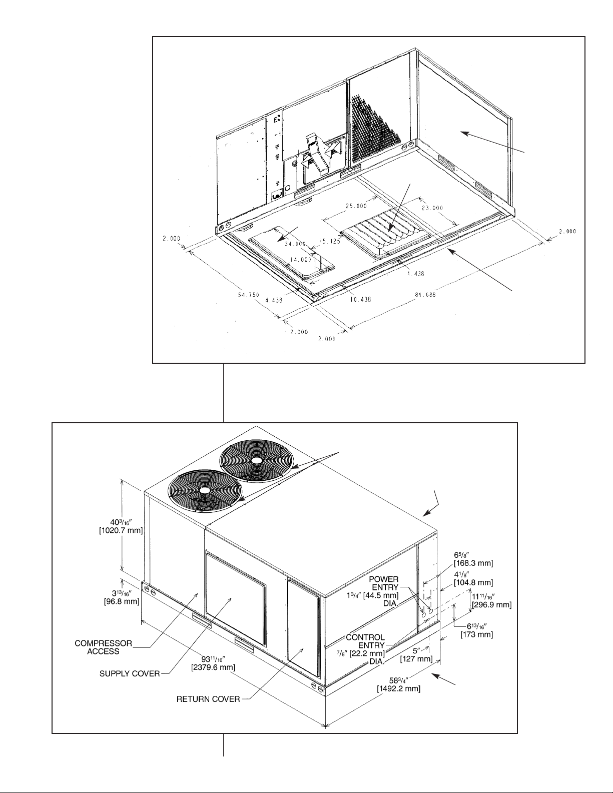
Unit
Dimensions
IMPORTANT: THIS
UNIT MUST BE
MOUNTED LEVEL IN
BOTH DIRECTIONS
TO ALLOW WATER
TO DRAIN FROM THE
CONDENSER SECTION AND CONDENSATE PAN.
ELECTRICAL
ACCESS
BLOWER
ACCESS
RETURN
AIR
COMPRESSOR
ACCESS
SUPPLY
AIR
CONDENSER
COIL
(RIGHT SIDE)
REAR SIDE
FIGURE 2
CABINET DIMENSIONS
AND ACCESS LOCATIONS
CONDENSER FANS
FRONT
SIDE
T-A1154-01-00
S
LEFT
SIDE
7
Page 8
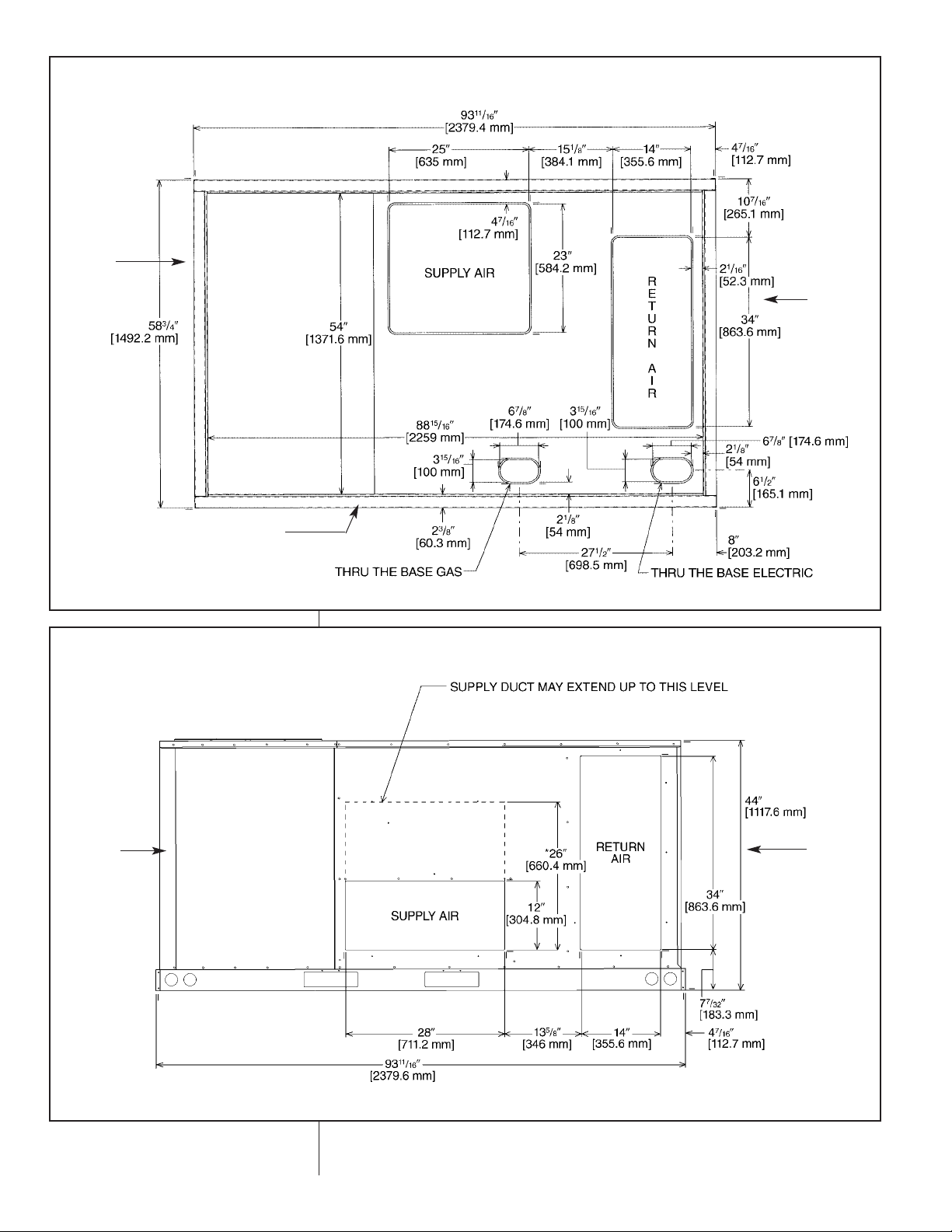
FIGURE 3
S
UPPLY AND RETURN DIMENSIONS FOR DOWNFLOW APPLICATIONS
Illustration
ST-A0738-02
SUPPLY AND RETURN DIMENSIONS FOR HORIZONTAL APPLICATIONS
*RECOMMENDED DUCT DIMENSIONS ARE 26"
Illustration
ST-A0736-02-X1
RIGHT
SIDE
(BOTTOM VIEW)
LEFT
SIDE
FRONT
SIDE
FIGURE 4
COMPRESSOR
ACCESS
RIGHT
SIDE
(SIDE VIEW – REAR)
LEFT
SIDE
8
Page 9
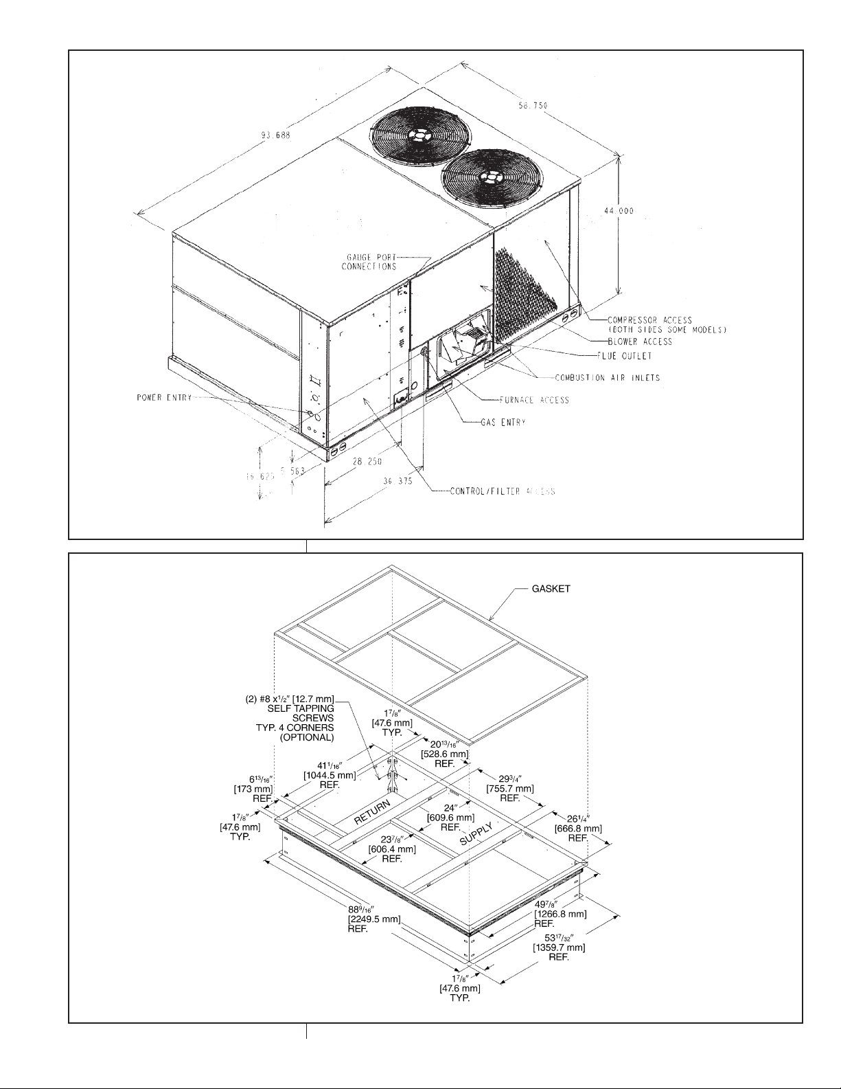
Illustration
ST-A0801-17
I
FIGURE 5
FIGURE 6
ROOFCURB INSTALLATION
T-A1154-02-00
S
9
Page 10

CONTINUED
GENERAL DATA - RKKL MODELS
NOM. SIZES 7.5, 10 AND 12.5 TON [26.4, 35.2 AND 44.0 kW]
Model RKKL-Series B090CL15E B090CL22E B090CM15E B090CM22E
Cooling Performance
Gross Cooling Capacity Btu [kW] 87,000 [25.49] 87,000 [25.49] 87,000 [25.49] 87,000 [25.49]
EER/SEER
Nominal CFM/AHRI Rated CFM [L/s] 2800/2925 [1321/1380] 2800/2925 [1321/1380] 2800/2925 [1321/1380] 2800/2925 [1321/1380]
ARI Net Cooling Capacity Btu [kW] 84,000 [24.61] 84,000 [24.61] 84,000 [24.61] 84,000 [24.61]
Net Sensible Capacity Btu [kW] 64,800 [18.99] 64,800 [18.99] 64,800 [18.99] 64,800 [18.99]
Net Latent Capacity Btu [kW] 19,200 [5.63] 19,200 [5.63] 19,200 [5.63] 19,200 [5.63]
IEER
Net System Power kW 7.5 7.5 7.5 7.5
Heating Performance (Gas)
Heating Input Btu [kW] (1st Stage / 2nd Stage) 75,000/150,000 [21.97/43.95] 75,000/150,000 [21.97/43.95] 75,000/150,000 [21.97/43.95] 75,000/150,000 [21.97/43.95]
Heating Output Btu [kW] (1st Stage / 2nd Stage) 60,750/121,500 [17.8/35.6] 91,125/182,250 [26.7/53.4] 60,750/121,500 [17.8/35.6] 91,125/182,250 [26.7/53.4]
Temperature Rise Range °F [°C] (1st Stage / 2nd Stage) 0-0 [0-0] / 25-55 [13.9-30.6] 0-0 [0-0] / 40-70 [22.2-38.9] 0-0 [0-0] / 25-55 [13.9-30.6] 0-0 [0-0] / 25-55 [22.2-38.9]
Steady State Efficiency (%) 81 81 81 81
No. Burners 6969
No. Stages 2222
Gas Connection Pipe Size in. [mm] 0.5 [12.7] 0.75 [19.05] 0.5 [12.7] 0.75 [19]
Compressor
No./Type 1/Scroll 1/Scroll 1/Scroll 1/Scroll
Outdoor Sound Rating (dB)
Outdoor Coil - Fin Type Louvered Louvered Louvered Louvered
Tube Type MicroChannel MicroChannel MicroChannel MicroChannel
MicroChannel Depth in. [mm] 1 [25.4] 1 [25.4] 1 [25.4] 1 [25.4]
Face Area sq. ft. [sq. m] 13.5 [1.25] 13.5 [1.25] 13.5 [1.25] 13.5 [1.25]
Rows / FPI [FPcm] 1 / 23 [9] 1 / 23 [9] 1 / 23 [9] 1 / 23 [9]
Indoor Coil - Fin Type Louvered Louvered Louvered Louvered
Tube Type Rifled Rifled Rifled Rifled
Tube Size in. [mm] 0.375 [9.5] 0.375 [9.5] 0.375 [9.5] 0.375 [9.5]
Face Area sq. ft. [sq. m] 13.5 [1.25] 13.5 [1.25] 13.5 [1.25] 13.5 [1.25]
Rows / FPI [FPcm] 2 / 18 [7] 2 / 18 [7] 2 / 18 [7] 2 / 18 [7]
Refrigerant Control Orifices Orifices Orifices Orifices
Drain Connection No./Size in. [mm] 1/1 [25.4] 1/1 [25.4] 1/1 [25.4] 1/1 [25.4]
Outdoor Fan - Type Propeller Propeller Propeller Propeller
No. Used/Diameter in. [mm] 1/24 [609.6] 1/24 [609.6] 1/24 [609.6] 1/24 [609.6]
Drive Type/No. Speeds Direct/1 Direct/1 Direct/1 Direct/1
CFM [L/s] 4500 [2124] 4500 [2124] 4500 [2124] 4500 [2124]
No. Motors/HP 1 at 1/2 HP 1 at 1/2 HP 1 at 1/2 HP 1 at 1/2 HP
Motor RPM 1075 1075 1075 1075
Indoor Fan - Type FC Centrifugal FC Centrifugal FC Centrifugal FC Centrifugal
No. Used/Diameter in. [mm] 1/15x15 [381x381] 1/15x15 [381x381] 1/15x15 [381x381] 1/15x15 [381x381]
Drive Type/No. Speeds Belt/Variable Belt/Variable Belt/Variable Belt/Variable
No. Motors 1111
Motor HP 2222
Motor RPM 1725 1725 1725 1725
Motor Frame Size 56 56 56 56
Filter - Type Disposable Disposable Disposable Disposable
Furnished Yes Yes Yes Yes
(NO.) Size Recommended in. [mm x mm x mm] (6)2x18x18 [51x457x457] (6)2x18x18 [51x457x457] (6)2x18x18 [51x457x457] (6)2x18x18 [51x457x457]
Refrigerant Charge Oz. [g] 117.6 [3334] 117.6 [3334] 117.6 [3334] 117.6 [3334]
Weights
Net Weights lbs. [kg] 882 [400] 918 [416] 882 [400] 918 [416]
Ship Weights lbs. [kg] 919 [417] 955 [433] 919 [417] 955 [433]
2
3
1
11.2/NA 11.2/NA 11.2/NA 11.2/NA
12.1 12.1 12.1 12.1
4
5
88 88 88 88
10
Page 11

CONTINUED
GENERAL DATA - RKKL MODELS
NOM. SIZES 7.5, 10 AND 12.5 TON [26.4, 35.2 AND 44.0 kW]
Model RKKL-Series B090CN15E B090CN22E B090DL15E B090DL22E
Cooling Performance
Gross Cooling Capacity Btu [kW] 87,000 [25.49] 87,000 [25.49] 87,000 [25.49] 87,000 [25.49]
2
EER/SEER
Nominal CFM/AHRI Rated CFM [L/s] 2800/2925 [1321/1380] 2800/2925 [1321/1380] 2800/2925 [1321/1380] 2800/2925 [1321/1380]
ARI Net Cooling Capacity Btu [kW] 84,000 [24.61] 84,000 [24.61] 84,000 [24.61] 84,000 [24.61]
Net Sensible Capacity Btu [kW] 64,800 [18.99] 64,800 [18.99] 64,800 [18.99] 64,800 [18.99]
Net Latent Capacity Btu [kW] 19,200 [5.63] 19,200 [5.63] 19,200 [5.63] 19,200 [5.63]
3
IEER
Net System Power kW 7.5 7.5 7.5 7.5
Heating Performance (Gas)
Heating Input Btu [kW] (1st Stage / 2nd Stage) 75,000/150,000 [21.97/43.95] 112,500/225,000 [32.96/65.92] 75,000/150,000 [21.97/43.95] 112,500/225,000 [32.96/65.92]
Heating Output Btu [kW] (1st Stage / 2nd Stage) 60,750/121,500 [17.8/35.6] 91,125/182,250 [26.7/53.4] 60,750/121,500 [17.8/35.6] 91,125/182,250 [26.7/53.4]
Temperature Rise Range °F [°C] (1st Stage / 2nd Stage) 0-0 [0-0] / 25-55 [13.9-30.6] 0-0 [0-0] / 40-70 [22.2-38.9] 0-0 [0-0] / 25-55 [13.9-30.6] 0-0 [0-0] / 25-55 [22.2-38.9]
Steady State Efficiency (%) 81 81 81 81
No. Burners 69 69
No. Stages 22 22
Gas Connection Pipe Size in. [mm] 0.5 [12.7] 0.75 [19.05] 0.5 [12.7] 0.75 [19]
Compressor
No./Type 1/Scroll 1/Scroll 1/Scroll 1/Scroll
Outdoor Sound Rating (dB)
Outdoor Coil - Fin Type Louvered Louvered Louvered Louvered
Tube Type MicroChannel MicroChannel MicroChannel MicroChannel
MicroChannel Depth in. [mm] 1 [25.4] 1 [25.4] 1 [25.4] 1 [25.4]
Face Area sq. ft. [sq. m] 13.5 [1.25] 13.5 [1.25] 13.5 [1.25] 13.5 [1.25]
Rows / FPI [FPcm] 1 / 23 [9] 1 / 23 [9] 1 / 23 [9] 1 / 23 [9]
Indoor Coil - Fin Type Louvered Louvered Louvered Louvered
Tube Type Rifled Rifled Rifled Rifled
Tube Size in. [mm] 0.375 [9.5] 0.375 [9.5] 0.375 [9.5] 0.375 [9.5]
Face Area sq. ft. [sq. m] 13.5 [1.25] 13.5 [1.25] 13.5 [1.25] 13.5 [1.25]
Rows / FPI [FPcm] 2 / 18 [7] 2 / 18 [7] 2 / 18 [7] 2 / 18 [7]
Refrigerant Control Orifices Orifices Orifices Orifices
Drain Connection No./Size in. [mm] 1/1 [25.4] 1/1 [25.4] 1/1 [25.4] 1/1 [25.4]
Outdoor Fan - Type Propeller Propeller Propeller Propeller
No. Used/Diameter in. [mm] 1/24 [609.6] 1/24 [609.6] 1/24 [609.6] 1/24 [609.6]
Drive Type/No. Speeds Direct/1 Direct/1 Direct/1 Direct/1
CFM [L/s] 4500 [2124] 4500 [2124] 4500 [2124] 4500 [2124]
No. Motors/HP 1 at 1/2 HP 1 at 1/2 HP 1 at 1/2 HP 1 at 1/2 HP
Motor RPM 1075 1075 1075 1075
Indoor Fan - Type FC Centrifugal FC Centrifugal FC Centrifugal FC Centrifugal
No. Used/Diameter in. [mm] 1/15x15 [381x381] 1/15x15 [381x381] 1/15x15 [381x381] 1/15x15 [381x381]
Drive Type/No. Speeds Belt/Variable Belt/Variable Belt/Variable Belt/Variable
No. Motors 11 11
Motor HP 33 22
Motor RPM 1725 1725 1725 1725
Motor Frame Size 56 56 56 56
Filter - Type Disposable Disposable Disposable Disposable
Furnished Yes Yes Yes Yes
(NO.) Size Recommended in. [mm x mm x mm] (6)2x18x18 [51x457x457] (6)2x18x18 [51x457x457] (6)2x18x18 [51x457x457] (6)2x18x18 [51x457x457]
Refrigerant Charge Oz. [g] 117.6 [3334] 117.6 [3334] 117.6 [3334] 117.6 [3334]
Weights
Net Weights lbs. [kg] 890 [404] 926 [420] 882 [400] 918 [416]
Ship Weights lbs. [kg] 927 [420] 963 [437] 919 [417] 955 [433]
1
11.2/NA 11.2/NA 11.2/NA 11.2/NA
12.1 12.1 12.1 12.1
4
5
88 88 88 88
11
Page 12

CONTINUED
GENERAL DATA - RKKL MODELS
NOM. SIZES 7.5, 10 AND 12.5 TON [26.4, 35.2 AND 44.0 kW]
Model RKKL-Series B090DM15E B090DM22E B090DN15E B090DN22E
Cooling Performance
Gross Cooling Capacity Btu [kW] 87,000 [25.49] 87,000 [25.49] 87,000 [25.49] 87,000 [25.49]
EER/SEER
Nominal CFM/AHRI Rated CFM [L/s] 2800/2925 [1321/1380] 2800/2925 [1321/1380] 2800/2925 [1321/1380] 2800/2925 [1321/1380]
ARI Net Cooling Capacity Btu [kW] 84,000 [24.61] 84,000 [24.61] 84,000 [24.61] 84,000 [24.61]
Net Sensible Capacity Btu [kW] 64,800 [18.99] 64,800 [18.99] 64,800 [18.99] 64,800 [18.99]
Net Latent Capacity Btu [kW] 19,200 [5.63] 19,200 [5.63] 19,200 [5.63] 19,200 [5.63]
IEER
Net System Power kW 7.5 7.5 7.5 7.5
Heating Performance (Gas)
Heating Input Btu [kW] (1st Stage / 2nd Stage) 75,000/150,000 [21.97/43.95] 112,500/225,000 [32.96/65.92] 75,000/150,000 [21.97/43.95] 112,500/225,000 [32.96/65.92]
Heating Output Btu [kW] (1st Stage / 2nd Stage) 60,750/121,500 [17.8/35.6] 91,125/182,250 [26.7/53.4] 60,750/121,500 [17.8/35.6] 91,125/182,250 [26.7/53.4]
Temperature Rise Range °F [°C] (1st Stage / 2nd Stage) 0-0 [0-0] / 25-55 [13.9-30.6] 0-0 [0-0] / 40-70 [22.2-38.9] 0-0 [0-0] / 25-55 [13.9-30.6] 0-0 [0-0] / 25-55 [22.2-38.9]
Steady State Efficiency (%) 81 81 81 81
No. Burners 69 69
No. Stages 22 22
Gas Connection Pipe Size in. [mm] 0.5 [12.7] 0.75 [19.05] 0.5 [12.7] 0.75 [19]
Compressor
No./Type 1/Scroll 1/Scroll 1/Scroll 1/Scroll
Outdoor Sound Rating (dB)
Outdoor Coil - Fin Type Louvered Louvered Louvered Louvered
Tube Type MicroChannel MicroChannel MicroChannel MicroChannel
MicroChannel Depth in. [mm] 1 [25.4] 1 [25.4] 1 [25.4] 1 [25.4]
Face Area sq. ft. [sq. m] 13.5 [1.25] 13.5 [1.25] 13.5 [1.25] 13.5 [1.25]
Rows / FPI [FPcm] 1 / 23 [9] 1 / 23 [9] 1 / 23 [9] 1 / 23 [9]
Indoor Coil - Fin Type Louvered Louvered Louvered Louvered
Tube Type Rifled Rifled Rifled Rifled
Tube Size in. [mm] 0.375 [9.5] 0.375 [9.5] 0.375 [9.5] 0.375 [9.5]
Face Area sq. ft. [sq. m] 13.5 [1.25] 13.5 [1.25] 13.5 [1.25] 13.5 [1.25]
Rows / FPI [FPcm] 2 / 18 [7] 2 / 18 [7] 2 / 18 [7] 2 / 18 [7]
Refrigerant Control Orifices Orifices Orifices Orifices
Drain Connection No./Size in. [mm] 1/1 [25.4] 1/1 [25.4] 1/1 [25.4] 1/1 [25.4]
Outdoor Fan - Type Propeller Propeller Propeller Propeller
No. Used/Diameter in. [mm] 1/24 [609.6] 1/24 [609.6] 1/24 [609.6] 1/24 [609.6]
Drive Type/No. Speeds Direct/1 Direct/1 Direct/1 Direct/1
CFM [L/s] 4500 [2124] 4500 [2124] 4500 [2124] 4500 [2124]
No. Motors/HP 1 at 1/2 HP 1 at 1/2 HP 1 at 1/2 HP 1 at 1/2 HP
Motor RPM 1075 1075 1075 1075
Indoor Fan - Type FC Centrifugal FC Centrifugal FC Centrifugal FC Centrifugal
No. Used/Diameter in. [mm] 1/15x15 [381x381] 1/15x15 [381x381] 1/15x15 [381x381] 1/15x15 [381x381]
Drive Type/No. Speeds Belt/Variable Belt/Variable Belt/Variable Belt/Variable
No. Motors 11 11
Motor HP 22 33
Motor RPM 1725 1725 1725 1725
Motor Frame Size 56 56 56 56
Filter - Type Disposable Disposable Disposable Disposable
Furnished Yes Yes Yes Yes
(NO.) Size Recommended in. [mm x mm x mm] (6)2x18x18 [51x457x457] (6)2x18x18 [51x457x457] (6)2x18x18 [51x457x457] (6)2x18x18 [51x457x457]
Refrigerant Charge Oz. [g] 117.6 [3334] 117.6 [3334] 117.6 [3334] 117.6 [3334]
Weights
Net Weights lbs. [kg] 882 [400] 918 [416] 890 [404] 926 [420]
Ship Weights lbs. [kg] 919 [417] 955 [433] 927 [420] 963 [437]
2
3
1
11.2/NA 11.2/NA 11.2/NA 11.2/NA
12.1 12.1 12.1 12.1
4
5
88 88 88 88
12
Page 13

GENERAL DATA - RKKL MODELS
NOM. SIZES 7.5, 10 AND 12.5 TON [26.4, 35.2 AND 44.0 kW]
Model RKKL-Series B090YL22E B090YM22E B090YN22E
Cooling Performance
Gross Cooling Capacity Btu [kW] 87,000 [25.49] 87,000 [25.49] 87,000 [25.49]
2
EER/SEER
Nominal CFM/AHRI Rated CFM [L/s] 2800/2925 [1321/1380] 2800/2925 [1321/1380] 2800/2925 [1321/1380]
ARI Net Cooling Capacity Btu [kW] 84,000 [24.61] 84,000 [24.61] 84,000 [24.61]
Net Sensible Capacity Btu [kW] 64,800 [18.99] 64,800 [18.99] 64,800 [18.99]
Net Latent Capacity Btu [kW] 19,200 [5.63] 19,200 [5.63] 19,200 [5.63]
3
IEER
Net System Power kW 7.5 7.5 7.5
Heating Performance (Gas)
Heating Input Btu [kW] (1st Stage / 2nd Stage) 112,500/225,000 [32.96/65.92] 112,500/225,000 [32.96/65.92]112,500/225,000 [32.96/65.92]
Heating Output Btu [kW] (1st Stage / 2nd Stage) 91,125/182,250 [26.7/53.4] 91,125/182,250 [26.7/53.4] 91,125/182,250 [26.7/53.4]
Temperature Rise Range °F [°C] (1st Stage / 2nd Stage) 0-0 [0-0] / 40-70 [22.2-38.9] 0-0 [0-0] / 40-70 [22.2-38.9] 0-0 [0-0] / 40-70 [22.2-38.9]
Steady State Efficiency (%) 81 81 81
No. Burners 696
No. Stages 222
Gas Connection Pipe Size in. [mm] 0.75 [19.05] 0.75 [19.05] 0.75 [19.05]
Compressor
No./Type 1/Scroll 1/Scroll 1/Scroll
Outdoor Sound Rating (dB)
Outdoor Coil - Fin Type Louvered Louvered Louvered
Tube Type MicroChannel MicroChannel MicroChannel
MicroChannel Depth in. [mm] 1 [25.4] 1 [25.4] 1 [25.4]
Face Area sq. ft. [sq. m] 13.5 [1.25] 13.5 [1.25] 13.5 [1.25]
Rows / FPI [FPcm] 1 / 23 [9] 1 / 23 [9] 1 / 23 [9]
Indoor Coil - Fin Type Louvered Louvered Louvered
Tube Type Rifled Rifled Rifled
Tube Size in. [mm] 0.375 [9.5] 0.375 [9.5] 0.375 [9.5]
Face Area sq. ft. [sq. m] 13.5 [1.25] 13.5 [1.25] 13.5 [1.25]
Rows / FPI [FPcm] 2 / 18 [7] 2 / 18 [7] 2 / 18 [7]
Refrigerant Control Orifices Orifices Orifices
Drain Connection No./Size in. [mm] 1/1 [25.4] 1/1 [25.4] 1/1 [25.4]
Outdoor Fan - Type Propeller Propeller Propeller
No. Used/Diameter in. [mm] 1/24 [609.6] 1/24 [609.6] 1/24 [609.6]
Drive Type/No. Speeds Direct/1 Direct/1 Direct/1
CFM [L/s] 4500 [2124] 4500 [2124] 4500 [2124]
No. Motors/HP 1 at 1/2 HP 1 at 1/2 HP 1 at 1/2 HP
Motor RPM 1075 1075 1075
Indoor Fan - Type FC Centrifugal FC Centrifugal FC Centrifugal
No. Used/Diameter in. [mm] 1/15x15 [381x381] 1/15x15 [381x381] 1/15x15 [381x381]
Drive Type/No. Speeds Belt/Variable Belt/Variable Belt/Variable
No. Motors 111
Motor HP 223
Motor RPM 1725 1725 1725
Motor Frame Size 56 56 56
Filter - Type Disposable Disposable Disposable
Furnished Yes Yes Yes
(NO.) Size Recommended in. [mm x mm x mm] (6)2x18x18 [51x457x457] (6)2x18x18 [51x457x457] (6)2x18x18 [51x457x457]
Refrigerant Charge Oz. [g] 117.6 [3334] 117.6 [3334] 117.6 [3334]
Weights
Net Weights lbs. [kg] 918 [416] 918 [416] 926 [420]
Ship Weights lbs. [kg] 955 [433] 955 [433] 963 [437]
1
11.2/NA 11.2/NA 11.2/NA
12.1 12.1 12.1
4
5
88 88 88
13
Page 14

Model RKKL- Serie
s
B120CL15
E
B120CL22
E
B120CM15
E
B120CM22
E
Cooling Performance
1
Continued ->
Gross Cooling Capacity Btu [kW] 123,000 [36.04] 123,000 [36.04] 123,000 [36.04] 123,000 [36.04]
EER/SEER
2
11.2/NA 11.2/NA 11.2/NA 11.2/NA
Nominal CFM/AHRI Rated CFM [L/s] 4000/3600 [1888/1699
]
4000/3600 [1888/1699
]
4000/3600 [1888/1699
]
4000/3600 [1888/1699
]
AHRI Net Cooling Capacity Btu [kW] 119,000 [34.87] 119,000 [34.87] 119,000 [34.87] 119,000 [34.87]
Net Sensible Capacity Btu [kW] 87,200 [25.55] 87,200 [25.55] 87,200 [25.55] 87,200 [25.55]
Net Latent Capacity Btu [kW] 31,800 [9.32] 31,800 [9.32] 31,800 [9.32] 31,800 [9.32]
IEER
3
12.2 12.2 12.2 12.2
Net System Power kW 10.62 10.62 10.62 10.62
H
eating Performance (Gas)
4
Heating Input Btu [kW] (1st Stage / 2nd Stage
)
75,000/150,000 [21.97/43.95
]
112,500/225,000 [32.96/65.92
]
75,000/150,000 [21.97/43.95]112,500/225,000 [32.96/65.92
]
Heating Output Btu [kW] (1st Stage / 2nd Stage
)
60,750/121,500 [17.8/35.6
]
91,125/182,250 [26.7/53.4
]
60,750/121,500 [17.8/35.6]91,125/182,250 [26.7/53.4
]
T
emperature Rise Range ºF [ºC] (1st Stage / 2nd Stage
)
1
5-45 [8.3-25] / 15-45 [8.3-25
]
2
5-55 [13.9-30.6] / 25-55 [13.9-30.6
]
1
5-45 [8.3-25] / 15-45 [8.3-25
]
2
5-55 [13.9-30.6] / 25-55 [13.9-30.6
Steady State Efficiency (%) 81 81 81 81
No. Burner
s
6969
No. Stages 2 2 2 2
Gas Connection Pipe Size in. [mm] 0.5 [12.7] 0.75 [19] 0.5 [12.7] 0.75 [19]
Compressor
No./Type 1/Scroll 1/Scroll 1/Scroll 1/Scroll
Outdoor Sound Rating (dB)
5
88 88 88 88
Outdoor Coil - Fin Type Louvered Louvered Louvered Louvered
Tube Type MicroChannel MicroChannel MicroChannel MicroChannel
MicroChannel Depth in. [mm] 1 [25.4] 1 [25.4] 1 [25.4] 1 [25.4]
Face Area sq. ft. [sq. m] 27 [2.51] 27 [2.51] 27 [2.51] 27 [2.51]
Rows / FPI [FPcm] 1 / 23 [9] 1 / 23 [9] 1 / 23 [9] 1 / 23 [9]
Indoor Coil - Fin Type Louvered Louvered Louvered Louvered
Tube Type Rifled Rifled Rifled Rifled
Tube Size in. [mm] 0.375 [9.5] 0.375 [9.5] 0.375 [9.5] 0.375 [9.5]
Face Area sq. ft. [sq. m] 13.5 [1.25] 13.5 [1.25] 13.5 [1.25] 13.5 [1.25]
Rows / FPI [FPcm] 2 / 22 [9] 2 / 22 [9] 2 / 22 [9] 2 / 22 [9]
Refrigerant Control Orifices Orifices Orifices Orifices
Drain Connection No./Size in. [mm
]
1/1 [25.4] 1/1 [25.4] 1/1 [25.4] 1/1 [25.4]
Outdoor Fan - Type Propelle
r
Propelle
r
Propelle
r
Propelle
r
No. Used/Diameter in. [mm] 2/24 [609.6] 2/24 [609.6] 2/24 [609.6] 2/24 [609.6]
Drive Type/No. Speeds Direct/1 Direct/1 Direct/1 Direct/1
CFM [L/s] 8400 [3964] 8400 [3964] 8400 [3964] 8400 [3964]
No. Motors/HP 2 at 1/3 HP 2 at 1/3 HP 2 at 1/3 HP 2 at 1/3 HP
Motor RPM 1075 1075 1075 1075
Indoor Fan - Type FC Centrifugal FC Centrifugal FC Centrifugal FC Centrifugal
No. Used/Diameter in. [mm] 1/15x15 [381x381] 1/15x15 [381x381] 1/15x15 [381x381] 1/15x15 [381x381]
Drive Type/No. Speeds Belt/Variabl
e
Belt/Variabl
e
Belt/Variabl
e
Belt/Variabl
e
No. Motors 1 1 1 1
Motor HP 2 2 3 3
Motor RPM 1725 1725 1725 1725
Motor Frame Size 56 56 56 56
Filter - Type Disposable Disposable Disposable Disposable
Furnished Yes Yes Yes Yes
(NO.) Size Recommended in. [mm x mm x mm] (6)2x18x18 [51x457x457
]
(6)2x18x18 [51x457x457
]
(6)2x18x18 [51x457x457
]
(6)2x18x18 [51x457x457
]
Refrigerant Charge Oz. [g] 204.8 [5806] 204.8 [5806] 204.8 [5806] 204.8 [5806]
Weights
Net Weight lbs. [kg] 984 [446] 1020 [463] 992 [450] 1028 [466]
Ship Weight lbs. [kg] 1021 [463] 1057 [479] 1029 [467] 1065 [483]
GENERAL DATA - RKKL MODELS
NOM. SIZES 7.5, 10 AND 12.5 TON [26.4, 35.2 AND 44.0 kW]
14
Page 15

Model RKKL- Serie
s
B120DL15E B120DL22E B120DM15E B120DM22E
Cooling Performance
1
Continued ->
Gross Cooling Capacity Btu [kW] 123,000 [36.04] 123,000 [36.04] 123,000 [36.04] 123,000 [36.04]
EER/SEER
2
11.2/NA 11.2/NA 11.2/NA 11.2/NA
Nominal CFM/AHRI Rated CFM [L/s] 4000/3600 [1888/1699
]
4000/3600 [1888/1699
]
4000/3600 [1888/1699
]
4000/3600 [1888/1699
]
AHRI Net Cooling Capacity Btu [kW] 119,000 [34.87] 119,000 [34.87] 119,000 [34.87] 119,000 [34.87]
Net Sensible Capacity Btu [kW] 87,200 [25.55] 87,200 [25.55] 87,200 [25.55] 87,200 [25.55]
Net Latent Capacity Btu [kW] 31,800 [9.32] 31,800 [9.32] 31,800 [9.32] 31,800 [9.32]
IEER
3
12.2 12.2 12.2 12.2
Net System Power kW 10.62 10.62 10.62 10.62
H
eating Performance (Gas)
4
Heating Input Btu [kW] (1st Stage / 2nd Stage
)
75,000/150,000 [21.97/43.95
]
112,500/225,000 [32.96/65.92
]
75,000/150,000 [21.97/43.95]112,500/225,000 [32.96/65.92
]
Heating Output Btu [kW] (1st Stage / 2nd Stage
)
60,750/121,500 [17.8/35.6
]
91,125/182,250 [26.7/53.4
]
60,750/121,500 [17.8/35.6]91,125/182,250 [26.7/53.4
]
T
emperature Rise Range ºF [ºC] (1st Stage / 2nd Stage
)
1
5-45 [8.3-25] / 15-45 [8.3-25
]
2
5-55 [13.9-30.6] / 25-55 [13.9-30.6
]
1
5-45 [8.3-25] / 15-45 [8.3-25
]
2
5-55 [13.9-30.6] / 25-55 [13.9-30.6
Steady State Efficiency (%) 81 81 81 81
No. Burner
s
6969
No. Stages 2 2 2 2
Gas Connection Pipe Size in. [mm] 0.5 [12.7] 0.75 [19] 0.5 [12.7] 0.75 [19]
Compressor
No./Type 1/Scroll 1/Scroll 1/Scroll 1/Scroll
Outdoor Sound Rating (dB)
5
88 88 88 88
Outdoor Coil - Fin Type Louvered Louvered Louvered Louvered
Tube Type MicroChannel MicroChannel MicroChannel MicroChannel
MicroChannel Depth in. [mm] 1 [25.4] 1 [25.4] 1 [25.4] 1 [25.4]
Face Area sq. ft. [sq. m] 27 [2.51] 27 [2.51] 27 [2.51] 27 [2.51]
Rows / FPI [FPcm] 1 / 23 [9] 1 / 23 [9] 1 / 23 [9] 1 / 23 [9]
Indoor Coil - Fin Type Louvered Louvered Louvered Louvered
Tube Type Rifled Rifled Rifled Rifled
Tube Size in. [mm] 0.375 [9.5] 0.375 [9.5] 0.375 [9.5] 0.375 [9.5]
Face Area sq. ft. [sq. m] 13.5 [1.25] 13.5 [1.25] 13.5 [1.25] 13.5 [1.25]
Rows / FPI [FPcm] 2 / 22 [9] 2 / 22 [9] 2 / 22 [9] 2 / 22 [9]
Refrigerant Control Orifices Orifices Orifices Orifices
Drain Connection No./Size in. [mm
]
1/1 [25.4] 1/1 [25.4] 1/1 [25.4] 1/1 [25.4]
Outdoor Fan - Type Propelle
r
Propelle
r
Propelle
r
Propelle
r
No. Used/Diameter in. [mm] 2/24 [609.6] 2/24 [609.6] 2/24 [609.6] 2/24 [609.6]
Drive Type/No. Speeds Direct/1 Direct/1 Direct/1 Direct/1
CFM [L/s] 8400 [3964] 8400 [3964] 8400 [3964] 8400 [3964]
No. Motors/HP 2 at 1/3 HP 2 at 1/3 HP 2 at 1/3 HP 2 at 1/3 HP
Motor RPM 1075 1075 1075 1075
Indoor Fan - Type FC Centrifugal FC Centrifugal FC Centrifugal FC Centrifugal
No. Used/Diameter in. [mm] 1/15x15 [381x381] 1/15x15 [381x381] 1/15x15 [381x381] 1/15x15 [381x381]
Drive Type/No. Speeds Belt/Variabl
e
Belt/Variabl
e
Belt/Variabl
e
Belt/Variabl
e
No. Motors 1 1 1 1
Motor HP 2 2 3 3
Motor RPM 1725 1725 1725 1725
Motor Frame Size 56 56 56 56
Filter - Type Disposable Disposable Disposable Disposable
Furnished Yes Yes Yes Yes
(NO.) Size Recommended in. [mm x mm x mm] (6)2x18x18 [51x457x457
]
(6)2x18x18 [51x457x457
]
(6)2x18x18 [51x457x457
]
(6)2x18x18 [51x457x457
]
Refrigerant Charge Oz. [g] 204.8 [5806] 204.8 [5806] 204.8 [5806] 204.8 [5806]
Weights
Net Weight lbs. [kg] 984 [446] 1020 [463] 992 [450] 1028 [466]
Ship Weight lbs. [kg] 1021 [463] 1057 [479] 1029 [467] 1065 [483]
GENERAL DATA - RKKL MODELS
NOM. SIZES 7.5, 10 AND 12.5 TON [26.4, 35.2 AND 44.0 kW]
15
Page 16

CONTINUED
GENERAL DATA - RKKL MODELS
NOM. SIZES 7.5, 10 AND 12.5 TON [26.4, 35.2 AND 44.0 kW]
Model RKKL-Series B120YL22E B120YM22E B151CL15E B151CL25E
Cooling Performance
Gross Cooling Capacity Btu [kW] 123,000 [36.04] 123,000 [36.04] 156,000 [45.71] 156,000 [45.71]
EER/SEER
Nominal CFM/AHRI Rated CFM [L/s] 4000/3600 [1888/1699] 4000/3600 [1888/1699] 5000/4225 [2360/1994] 5000/4225 [2360/1994]
ARI Net Cooling Capacity Btu [kW] 119,000 [34.87] 119,000 [34.87] 150,000 [43.95] 150,000 [43.95]
Net Sensible Capacity Btu [kW] 87,200 [25.55] 87,200 [25.55] 106,600 [31.23] 106,600 [31.23]
Net Latent Capacity Btu [kW] 31,800 [9.32] 31,800 [9.32] 43,400 [12.72] 43,400 [12.72]
3
IEER
Net System Power kW 10.62 10.62 13.54 13.54
Heating Performance (Gas)
Heating Input Btu [kW] (1st Stage / 2nd Stage) 112,500/225,000 [32.96/65.92] 112,500/225,000 [32.96/65.92] 75,000/150,000 [21.97/43.95] 126,000/252,000 [36.92/73.84]
Heating Output Btu [kW] (1st Stage / 2nd Stage) 91,125/182,250 [26.7/53.4] 91,125/182,250 [26.7/53.4] 60,750/121,500 [17.8/35.6] 102,000/204,000 [29.89/59.77]
Temperature Rise Range °F [°C] (1st Stage / 2nd Stage) 25-55 [13.9-30.6] / 25-55 [13.9-30.6] 25-55 [13.9-30.6] / 25-55 [13.9-30.6] 15-45 [8.3-25] / 15-45 [8.3-25] 25-55 [13.9-30.6] / 25-55 [13.9-30.6]
Steady State Efficiency (%) 81 81 81 81
No. Burners 9969
No. Stages 2222
Gas Connection Pipe Size in. [mm] 0.75 [19.05] 0.75 [19] 0.5 [12.7] 0.75 [19]
Compressor
No./Type 1/Scroll 1/Scroll 2/Scroll 2/Scroll
Outdoor Sound Rating (dB)
Outdoor Coil - Fin Type Louvered Louvered Louvered Louvered
Tube Type MicroChannel MicroChannel MicroChannel MicroChannel
MicroChannel Depth in. [mm] 1 [25.4] 1 [25.4] 1 [25.4] 1 [25.4]
Face Area sq. ft. [sq. m] 27 [2.51] 27 [2.51] 27 [2.51] 27 [2.51]
Rows / FPI [FPcm] 1 / 23 [9] 1 / 23 [9] 2 / 23 [9] 2 / 23 [9]
Indoor Coil - Fin Type Louvered Louvered Louvered Louvered
Tube Type Rifled Rifled Rifled Rifled
Tube Size in. [mm] 0.375 [9.5] 0.375 [9.5] 0.375 [9.5] 0.375 [9.5]
Face Area sq. ft. [sq. m] 13.5 [1.25] 13.5 [1.25] 13.5 [1.25] 13.5 [1.25]
Rows / FPI [FPcm] 2 / 22 [9] 2 / 22 [9] 4 / 15 [6] 4 / 15 [6]
Refrigerant Control Orifices Orifices TX Valves TX Valves
Drain Connection No./Size in. [mm] 1/1 [25.4] 1/1 [25.4] 1/1 [25.4] 1/1 [25.4]
Outdoor Fan - Type Propeller Propeller Propeller Propeller
No. Used/Diameter in. [mm] 2/24 [609.6] 2/24 [609.6] 1/24 [609.6] 1/24 [609.6]
Drive Type/No. Speeds Direct/1 Direct/1 Direct/1 Direct/1
CFM [L/s] 8400 [3964] 8400 [3694] 8000 [3775] 8000 [3775]
No. Motors/HP 2 at 1/3 HP 2 at 1/3 HP 2 at 1/2 HP 2 at 1/2 HP
Motor RPM 1075 1075 1075 1075
Indoor Fan - Type FC Centrifugal FC Centrifugal FC Centrifugal FC Centrifugal
No. Used/Diameter in. [mm] 1/15x15 [381x381] 1/15x15 [381x381] 1/15x15 [381x381] 1/15x15 [381x381]
Drive Type/No. Speeds Belt/Variable Belt/Variable Belt/Variable Belt/Variable
No. Motors 1111
Motor HP 2233
Motor RPM 1725 1725 1725 1725
Motor Frame Size 56 56 56 56
Filter - Type Disposable Disposable Disposable Disposable
Furnished Yes Yes Yes Yes
(NO.) Size Recommended in. [mm x mm x mm] (6)2x18x18 [51x457x457] (6)2x18x18 [51x457x457] (6)2x18x18 [51x457x457] (6)2x18x18 [51x457x457]
Refrigerant Charge Oz. [g] 117.6 [3334] 117.6 [3334] 147.2/152 [4173/4309] 147.2/152 [4173/4309]
Weights
Net Weights lbs. [kg] 882 [400] 918 [416] 1230 [558] 1266 [574]
Ship Weights lbs. [kg] 919 [417] 955 [433] 1267 [575] 1303 [591]
1
2
4
5
11.2/NA 11.2/NA 11.1/NA 11.1/NA
12.2 12.2 10.8 10.8
88 88 88 88
16
Page 17

CONTINUED
GENERAL DATA - RKKL MODELS
NOM. SIZES 7.5, 10 AND 12.5 TON [26.4, 35.2 AND 44.0 kW]
Model RKKL-Series B151CM15E B151CM25E B151DL15E B151DL25E
Cooling Performance
Gross Cooling Capacity Btu [kW] 156,000 [45.71] 156,000 [45.71] 156,000 [45.71] 156,000 [45.71]
EER/SEER
Nominal CFM/AHRI Rated CFM [L/s] 5000/4225 [2360/1994] 5000/4225 [2360/1994] 5000/4225 [2360/1994] 5000/4225 [2360/1994]
ARI Net Cooling Capacity Btu [kW] 150,000 [43.95] 150,000 [43.95] 150,000 [43.95] 150,000 [43.95]
Net Sensible Capacity Btu [kW] 106,600 [31.23] 106,600 [31.23] 106,600 [31.23] 106,600 [31.23]
Net Latent Capacity Btu [kW] 43,400 [12.72] 43,400 [12.72] 43,400 [12.72] 43,400 [12.72]
3
IEER
Net System Power kW 13.54 13.54 13.54 13.54
Heating Performance (Gas)
Heating Input Btu [kW] (1st Stage / 2nd Stage) 75,000/150,000 [21.97/43.95] 126,000/252,000 [36.92/73.84] 75,000/150,000 [21.97/43.95] 126,000/252,000 [36.92/73.84]
Heating Output Btu [kW] (1st Stage / 2nd Stage) 60,750/121,500 [17.8/35.6] 102,000/204,000 [29.89/59.77] 60,750/121,500 [17.8/35.6] 102,000/204,000 [29.89/59.77]
Temperature Rise Range °F [°C] (1st Stage / 2nd Stage) 15-45 [8.3-25] / 15-45 [8.3-25] 25-55 [13.9-30.6] / 25-55 [13.9-30.6] 15-45 [8.3-25] / 15-45 [8.3-25] 25-55 [13.9-30.6] / 25-55 [13.9-30.6]
Steady State Efficiency (%) 81 81 81 81
No. Burners 6969
No. Stages 222
Gas Connection Pipe Size in. [mm] 0.5 [12.7] 0.75 [19] 0.5 [12.7] 0.75 [19]
Compressor
No./Type 2/Scroll 2/Scroll 2/Scroll 2/Scroll
Outdoor Sound Rating (dB)
Outdoor Coil - Fin Type Louvered Louvered Louvered Louvered
Tube Type MicroChannel MicroChannel MicroChannel MicroChannel
MicroChannel Depth in. [mm] 1 [25.4] 1 [25.4] 1 [25.4] 1 [25.4]
Face Area sq. ft. [sq. m] 27 [2.51] 27 [2.51] 27 [2.51] 27 [2.51]
Rows / FPI [FPcm] 2 / 23 [9] 2 / 23 [9] 2 / 23 [9] 2 / 23 [9]
Indoor Coil - Fin Type Louvered Louvered Louvered Louvered
Tube Type Rifled Rifled Rifled Rifled
Tube Size in. [mm] 0.375 [9.5] 0.375 [9.5] 0.375 [9.5] 0.375 [9.5]
Face Area sq. ft. [sq. m] 13.5 [1.25] 13.5 [1.25] 13.5 [1.25] 13.5 [1.25]
Rows / FPI [FPcm] 4 / 15 [6] 4 / 15 [6] 4 / 15 [6] 4 / 15 [6]
Refrigerant Control TX Valves TX Valves TX Valves TX Valves
Drain Connection No./Size in. [mm] 1/1 [25.4] 1/1 [25.4] 1/1 [25.4] 1/1 [25.4]
Outdoor Fan - Type Propeller Propeller Propeller Propeller
No. Used/Diameter in. [mm] 2/24 [609.6] 2/24 [609.6] 2/24 [609.6] 2/24 [609.6]
Drive Type/No. Speeds Direct/1 Direct/1 Direct/1 Direct/1
CFM [L/s] 8000 [3775] 8000 [3775] 8000 [3775] 8000 [3775]
No. Motors/HP 2 at 1/2 HP 2 at 1/2 HP 2 at 1/2 HP 2 at 1/2 HP
Motor RPM 1075 1075 1075 1075
Indoor Fan - Type FC Centrifugal FC Centrifugal FC Centrifugal FC Centrifugal
No. Used/Diameter in. [mm] 1/15x15 [381x381] 1/15x15 [381x381] 1/15x15 [381x381] 1/15x15 [381x381]
Drive Type/No. Speeds Belt/Variable Belt/Variable Belt/Variable Belt/Variable
No. Motors 1111
Motor HP 5533
Motor RPM 1725 1725 1725 1725
Motor Frame Size 184 184 56 56
Filter - Type Disposable Disposable Disposable Disposable
Furnished Yes Yes Yes Yes
(NO.) Size Recommended in. [mm x mm x mm] (6)2x18x18 [51x457x457] (6)2x18x18 [51x457x457] (6)2x18x18 [51x457x457] (6)2x18x18 [51x457x457]
Refrigerant Charge Oz. [g] 147.2/152 [4173/4309] 147.2/152 [4173/4309] 147.2/152 [4173/4309] 147.2/152 [4173/4309]
Weights
Net Weights lbs. [kg] 1238 [562] 1274 [574] 1230 [558] 1277 [574]
Ship Weights lbs. [kg] 1275 [578] 1311 [595] 1267 [575] 1303 [591]
1
2
4
5
11.1/NA 11.1/NA 11.1/NA 11.1/NA
10.8 10.8 10.8 10.8
88 88 88 88
17
Page 18

GENERAL DATA - RKKL MODELS
NOM. SIZES 7.5, 10 AND 12.5 TON [26.4, 35.2 AND 44.0 kW]
Model RKKL-Series B151DM15E B151DM25E B151YL25E B151YM25E
Cooling Performance
Gross Cooling Capacity Btu [kW] 156,000 [45.71] 156,000 [45.71] 156,000 [45.71] 156,000 [45.71]
EER/SEER
Nominal CFM/AHRI Rated CFM [L/s] 5000/4225 [2360/1994] 5000/4225 [2360/1994] 5000/4225 [2360/1994] 5000/4225 [2360/1994]
ARI Net Cooling Capacity Btu [kW] 150,000 [43.95] 150,000 [43.95] 150,000 [43.95] 150,000 [43.95]
Net Sensible Capacity Btu [kW] 106,600 [31.23] 106,600 [31.23] 106,600 [31.23] 106,600 [31.23]
Net Latent Capacity Btu [kW] 43,400 [12.72] 43,400 [12.72] 43,400 [12.72] 43,400 [12.72]
3
IEER
Net System Power kW 13.54 13.54 13.54 13.54
Heating Performance (Gas)
Heating Input Btu [kW] (1st Stage / 2nd Stage) 75,000/150,000 [21.97/43.95] 126,000/252,000 [36.92/73.84] 126,000/252,000 [36.92/73.84] 126,000/252,000 [36.92/73.84]
Heating Output Btu [kW] (1st Stage / 2nd Stage) 60,750/121,500 [17.8/35.6] 102,000/204,000 [29.89/59.77] 102,000/204,000 [29.89/59.77] 102,000/204,000 [29.89/59.77]
Temperature Rise Range °F [°C] (1st Stage / 2nd Stage) 15-45 [8.3-25] / 15-45 [8.3-25] 25-55 [13.9-30.6] / 25-55 [13.9-30.6] 25-55 [13.9-30.6] / 25-55 [13.9-30.6] 25-55 [13.9-30.6] / 25-55 [13.9-30.6]
Steady State Efficiency (%) 81 81 81 81
No. Burners 6999
No. Stages 2222
Gas Connection Pipe Size in. [mm] 0.5 [12.7] 0.75 [19] 0.75 [19] 0.75 [19]
Compressor
No./Type 2/Scroll 2/Scroll 2/Scroll 2/Scroll
Outdoor Sound Rating (dB)
Outdoor Coil - Fin Type Louvered Louvered Louvered Louvered
Tube Type MicroChannel MicroChannel MicroChannel MicroChannel
MicroChannel Depth in. [mm] 1 [25.4] 1 [25.4] 1 [25.4] 1 [25.4]
Face Area sq. ft. [sq. m] 27 [2.51] 27 [2.51] 27 [2.51] 27 [2.51]
Rows / FPI [FPcm] 2 / 23 [9] 2 / 23 [9] 2 / 23 [9] 2 / 23 [9]
Indoor Coil - Fin Type Louvered Louvered Louvered Louvered
Tube Type Rifled Rifled Rifled Rifled
Tube Size in. [mm] 0.375 [9.5] 0.375 [9.5] 0.375 [9.5] 0.375 [9.5]
Face Area sq. ft. [sq. m] 13.5 [1.25] 13.5 [1.25] 13.5 [1.25] 13.5 [1.25]
Rows / FPI [FPcm] 4 / 15 [6] 4 / 15 [6] 4 / 15 [6] 4 / 15 [6]
Refrigerant Control TX Valves TX Valves TX Valves TX Valves
Drain Connection No./Size in. [mm] 1/1 [25.4] 1/1 [25.4] 1/1 [25.4] 1/1 [25.4]
Outdoor Fan - Type Propeller Propeller Propeller Propeller
No. Used/Diameter in. [mm] 2/24 [609.6] 2/24 [609.6] 2/24 [609.6] 2/24 [609.6]
Drive Type/No. Speeds Direct/1 Direct/1 Direct/1 Direct/1
CFM [L/s] 8000 [3775] 8000 [3775] 8000 [3775] 8000 [3775]
No. Motors/HP 2 at 1/2 HP 2 at 1/2 HP 2 at 1/2 HP 2 at 1/2 HP
Motor RPM 1075 1075 1075 1075
Indoor Fan - Type FC Centrifugal FC Centrifugal FC Centrifugal FC Centrifugal
No. Used/Diameter in. [mm] 1/15x15 [381x381] 1/15x15 [381x381] 1/15x15 [381x381] 1/15x15 [381x381]
Drive Type/No. Speeds Belt/Variable Belt/Variable Belt/Variable Belt/Variable
No. Motors 1111
Motor HP 5535
Motor RPM 1725 1725 1725 1725
Motor Frame Size 184 184 56 184
Filter - Type Disposable Disposable Disposable Disposable
Furnished Yes Yes Yes Yes
(NO.) Size Recommended in. [mm x mm x mm] (6)2x18x18 [51x457x457] (6)2x18x18 [51x457x457] (6)2x18x18 [51x457x457] (6)2x18x18 [51x457x457]
Refrigerant Charge Oz. [g] 147.2/152 [4173/4309] 147.2/152 [4173/4309] 147.2/152 [4173/4309] 147.2/152 [4173/4309]
Weights
Net Weights lbs. [kg] 1238 [562] 1274 [574] 1266 [574] 1274 [574]
Ship Weights lbs. [kg] 1275 [578] 1311 [595] 1303 [591] 1311 [595]
1
2
4
5
11.1/NA 11.1/NA 11.1/NA 11.1/NA
10.8 10.8 10.8 10.8
88 88 88 88
18
Page 19

ELECTRICAL DATA - RKKL MODELS
ELECTRICAL DATA - RKKL SERIES
090CL B090CM B090CN B090DL B090DM B090DN B090YL B090YM B090YN
B
Unit Operating Voltage
Range
Volts
Minimum Circuit
Ampacity
Minimum Overcurrent
Protection Device Size
Unit Information
Maximum Overcurrent
Protection Device Size
Volts
Phase
RPM
HP, Compressor 1
Compressor Motor
Amps (RLA), Comp. 1
Amps (LRA), Comp. 1
Volts
Phase
No.
No.
187-253 187-253 187-253 414-506 414-506 414-506 518-632 518-632 518-632
08/230 208/230 208/230 460 460 460 575 575 575
2
40/40 40/40 45/45 20 20 23 15 15 19
0/50 50/50 60/60 25 25 30 20 20 25
5
60/60 60/60 60/60 30 30 30 20 20 25
1
200/240 200/240 200/240 480 480 480 600 600 600
333333333
450 3450 3450 3450 3450 3450 3450 3450 3450
3
666666666
3.2/23.2 23.2/23.2 23.2/23.2 11.2 11.2 11.2 7.9 7.9 7.9
2
164/164 164/164 164/164 75 75 75 54 54 54
111111111
208/230 208/230 208/230 460 460 460 575 575 575
111111111
11111111
Condenser MotorEvaporator Fan
Amps (FLA, each)
Amps (LRA, each)
Amps (FLA, each)
Amps (LRA, each)
HP
No.
Volts
Phase
HP
1/2 1/2 1/2 1/2 1/2 1/2 1/2 1/2 1/2
2.3/2.3 2.3/2.3 2.3/2.3 1.5 1.5 1.5 111
5.6/5.6 5.6/5.6 5.6/5.6 3.1 3.1 3.1 2.2 2.2 2.2
111111111
208/230 208/230 208/230 460 460 460 575 575 575
333333333
223223223
8/8 8/8 13/13 44 74 48
56/56 56/56 74.5/74.5 28 28 38.1 19 19 20
19
Page 20

Unit Operating Voltage
Range
Volts
Minimum Circuit
Ampacity
Minimum Overcurrent
Protection Device Size
Unit Information
Maximum Overcurrent
Protection Device Size
No.
ELECTRICAL DATA - RKKL SERIES
120CL B120CM B120DL B120DM B120YL B120YM B151CL B151CM B151DL B151DM B151YL B151YM
B
187-253 187-253 414-506 414-506 518-632 518-632 187-253 187-253 414-506 414-506 518-632 518-632
08/230 208/230 460 460 575 575 208/230 208/230 460 460 575 575
2
51/51 56/56 28 31 22 26 67/67 71/71 33 56 28 28
0/60 70/70 35 35 25 30 70/70 75/75 35 40 30 30
6
80/80 80/80 40 45 30 35 80/80 90/90 40 45 35 35
1
11 1 1 12 2 2 222
HP, Compressor 1
Amps (RLA), Comp. 1
Compressor Motor
Amps (LRA), Comp. 1
HP, Compressor 2
Amps (RLA), Comp. 2
Amps (LRA), Comp. 2
Condenser Motor
Amps (FLA, each)
Amps (LRA, each)
Volts
Phase
RPM
No.
Volts
Phase
HP
200/240 200/240 480 480 600 600 208/230 208/230 460 460 575 575
333 3 3 33 3 3 333
450 3450 3450 3450 3450 3450 3450 3450 3450 3450 3450 3450
3
10 10 10 10 10 10 5 3/4 5 3/4 5 3/4 5 3/4 5 3/4 5 3/4
0.1/30.1 30.1/30.1 16.7 16.7 12.2 12.2 22.4/22.4 22.4/22.4 10.6 10.6 7.7 7.7
3
225/225 225/225 114 114 80 80 149/149 149/149 75 75 54 54
5 1/4 5 1/4 5 1/4 5 1/4 5 1/4 5 1/4
19/19 19/19 9.7 9.7 7.4 7.4
123/123 123/123 62 62 50 50
222 2 2 22 2 2 222
208/230 208/230 460 460 575 575 208/230 208/230 460 460 575 575
111 1 1 11 1 1 111
1/3 1/3 1/3 1/3 1/3 1/3 1/2 1/2 1/2 1/2 1/2 1/2
2.4/2.4 2.4/2.4 1.4 1.4 112.3/2.3 2.3/2.3 1.5 1.5 11
4.7/4.7 4.7/4.7 2.4 2.4 1.5 1.5 5.6/5.6 5.6/5.6 3.1 3.1 2.2 2.2
20
Evaporator Fan
Amps (FLA, each)
Amps (LRA, each)
No.
Volts
Phase
HP
111 1 1 11 1 1 111
208/230 208/230 460 460 575 575 208/230 208/230 460 460 575 575
333 3 3 33 3 3 333
232 3 2 33 5 3 535
8/8 13/13 474815/15 18.8/18.8 7 10 88
56/56 74.5/74.5 28 38.1 19 20 74.5/74.5 82.6/82.6 38.1 41.3 20 33
Page 21

II. INSTALLATION
A. GENERAL
1. INSTALLATION — Install this unit in accordance with The American National
Standard Z223.1-latest edition booklet entitled “National Fuel Gas Code,” and the
equirements or codes of the local utility or other authority having jurisdiction.
r
Additional helpful publications available from the “National Fire Protection
Association” are: NFPA-90A - Installation of Air Conditioning and Ventilating
Systems 1985 or latest edition. NFPA-90B - Warm Air Heating and Air Conditioning
Systems 1984.
hese publications are available from:
T
National Fire Protection
Association, Inc.
Batterymarch Park
Quincy, MA 02269
2. PRE-INSTALLATION CHECK-POINTS — Before attempting any installation, carefully consider the following points:
Structural strength of supporting members (Rooftop Installation)
Clearances and provision for servicing
Power supply and wiring
Gas supply and piping
Air duct connections and sizing
Drain facilities and connections
Location for minimum noise and vibration - away from bedroom windows
B. LOCATION CONSIDERATIONS
The metal parts of this unit may be subject to rust or deterioration in adverse environmental conditions. This oxidation could shorten the equipment’s useful life. Salt spray,
fog or mist in seacoast areas, sulphur or chlorine from lawn watering systems, and various chemical contaminants from industries such as paper mills and petroleum refineries
are especially corrosive.
If the unit is to be installed in an area where contaminants are likely to be a problem, give special attention to the equipment location and exposure.
1. Avoid having lawn sprinkler heads spray directly on the unit cabinet.
2. In coastal areas locate the unit on the side of the building away from the waterfront.
3. Shielding by a fence or shrubs may give some protection.
WARNING
!
DISCONNECT ALL POWER TO UNIT BEFORE STARTING MAINTENANCE.
FAILURE TO DO SO CAN CAUSE ELECTRICAL SHOCK RESULTING IN PERSONAL INJURY OR DEATH. REGULAR MAINTENANCE WILL REDUCE THE
BUILDUP OF CONTAMINANTS AND HELP TO PROTECT THE UNIT’S FINISH.
1. Frequent washing of the cabinet, fan blade and coil with fresh water will remove
most of the salt or other contaminants that build up on the unit.
2. Regular cleaning and waxing of the cabinet with an automobile polish will provide
some protection.
3. A liquid cleaner may be used several times a year to remove matter that will not
wash off with water.
Several different types of protective coatings are offered in some areas. These coatings
may provide some benefit, but the effectiveness of such coating materials cannot be verified by the equipment manufacturer.
The best protection is frequent cleaning, maintenance and minimal exposure to
contaminants.
21
Page 22

FIGURE 7
UTSIDE SLAB INSTALLATION. CLOSET DISTRIBUTION SYSTEM. SLAB FLOOR CONSTRUCTION.
O
Y
L
P
P
T
U
C
S
U
RE
URN
T
DUCT
D
ST-A1111-03
C. OUTSIDE INSTALLATION
WARNING
!
THESE UNITS ARE DESIGNED CERTIFIED FOR OUTDOOR INSTALLATION
ONLY. INSTALLATION INSIDE ANY PART OF A STRUCTURE CAN RESULT IN
INADEQUATE UNIT PERFORMANCE AS WELL AS PROPERTY DAMAGE.
INSTALLATION INSIDE CAN ALSO CAUSE RECIRCULATION OF FLUE PRODUCTS INTO THE CONDITIONED SPACE RESULTING IN PERSONAL INJURY
OR DEATH.
(Typical outdoor slab installation is shown in Figure 7.)
1. Select a location where external water drainage cannot collect around unit.
2. Provide a level slab sufficiently high enough above grade to prevent surface water
from entering the unit
3. Locate the unit to provide proper access for inspection and servicing as shown in
Figure 9.
4. Locate unit where operating sounds will not disturb owner or neighbors.
5. Locate unit so roof runoff water does not pour directly on the unit. Provide gutter or
other shielding at roof level. Do not locate unit in an area where excessive snow
drifting may occur or accumulate.
6. Where snowfall is anticipated, the height of the unit above the ground level must be
considered. Mount unit high enough to be above anticipated maximum area snowfall
and to allow combustion air to enter the combustion air inlet.
7. Select an area which will keep the areas of the vent, air intake, and A/C condenser
fins free and clear of obstructions such as weeds, shrubs, vines, snow, etc. Inform
the user accordingly.
22
D. ATTACHING EXHAUST AND COMBUSTION AIR INLET HOODS
IMPORTANT: Do not operate this unit without the exhaust/combustion air inlet hood
properly installed. This hood is shipped in a carton in the blower compartment inside
the unit and must be attached when the unit is installed. See Figure 5.
Page 23

To attach exhaust/combustion air inlet hood:
1. Remove screws securing blower access panel and remove access panel. For location of
blower access panel, see Figure 5.
2. Remove exhaust/combustion air inlet hood from the carton, located inside the blower
compartment.
3. Attach blower access panel.
4. Attach the combustion air inlet/exhaust hood with screws. Reference Figure 5 for proper
location. Screws are in carton with the hood.
. Vent the unit using the flue exhaust hood, as supplied from the factory, without alteration
5
or addition. Consult your local utility or other authority having jurisdiction for accepted
venting techniques.
E.
COVER PANEL INSTALLATION/CONVERSION PROCEDURE
OWNFLOW TO HORIZONTAL
D
1. Remove the screws and covers from the outside of the supply and return sections.
See Figure 2.
2. Install the covers over the bottom supply and return openings, painted side up,
inserting the leading flange under the bracket provided. Place the back flange to top
of the front bracket provided. See Figure 8.
3. Secure the return and supply cover to front bracket with one (1) screw.
F.
FILTER REPLACEMENT
This unit is provided with 6 - 18” X 18” X 2” disposable filters. When replacing filters,
ensure they are inserted fully to the back to prevent bypass. See Figure 3.
Recommended supplier of this filter is Glassfloss Industries, Inc. or equivalent.
FIGURE 8
COVER GASKET DETAIL FOR UNITS SHIPPED FOR DOWNFLOW APPLICATION BEING CONVERTED TO HORIZONTAL
A074001
23
Page 24

FIGURE 9
LEARANCES
C
ST-A1111-03
G.
CLEARANCES
The following minimum clearances must be observed for proper unit performance and
serviceability. Reference Figure 9.
Recommended
Clearance
48” A - Front
18” B - Condenser Coil
18” C - Duct Side
18”* D - Evaporator End
60” E - Above
*Without Economizer. 48” With Economizer
H.
ROOFTOP INSTALLATION
1. Before locating the unit on the roof, make sure that the roof structure is adequate to
support the weight involved. (See Electrical & Physical Tables in this manual.) THIS
IS VERY IMPORTANT AND THE INSTALLER’S RESPONSIBILITY.
2. For rigging and roofcurb details, see Figures 11, 12 and 13.
3. The location of the unit on the roof should be such as to provide proper access for
inspection and servicing.
IMPORTANT: If unit will not be put into service immediately, block off supply and return
air openings to prevent excessive condensation.
Location
I. DUCTING
The installing contractor should fabricate ductwork in accordance with local codes. Use
industry manuals as a guide when sizing and designing the duct system. Contact Air
Conditioning Contractors of America, 1513 16th St. N.W., Washington, D.C. 20036.
24
WARNING
!
DO NOT, UNDER ANY CIRCUMSTANCES, CONNECT RETURN DUCTWORK TO
ANY OTHER HEAT PRODUCING DEVICE SUCH AS FIREPLACE INSERT,
STOVE, ETC. UNAUTHORIZED USE OF SUCH DEVICES MAY RESULT IN FIRE,
CARBON MONOXIDE POISONING, EXPLOSION, PERSONAL INJURY, PROPERTY DAMAGE OR DEATH.
Page 25

FIGURE 10A
LAT ROOFTOP INSTALLATION, ATTIC OR DROP CEILING DISTRIBUTING
F
YSTEM. MOUNTED ON ROOFCURB. CURB MUST BE LEVEL.
S
FIGURE 10B
LAT ROOFTOP INSTALLATION, ATTIC OR DROP CEILING DISTRIBUTING
F
YSTEM. MOUNTED ON ROOFCURB. CURB MUST BE LEVEL.
S
ST-A1111-03
ST-A1111-03
Place the unit as close to the conditioned space as possible allowing clearances as indicated. Run ducts as directly as possible to supply and return outlets. Use of non-flammable weatherproof flexible connectors on both supply and return connections at unit to
reduce noise transmission is recommended.
On ductwork exposed to outside temperature and humidity, use a minimum of 2” of
insulation and a vapor barrier. Distribution system in attic, furred space or crawl space
should be insulated with at least 2” of insulation. Half-inch to 1” thick insulation is usually
sufficient for ductwork inside the air conditioned space.
Provide balancing dampers for each branch duct in the supply system. Properly support
ductwork from the structure.
IMPORTANT: In the event that the return air ducts must be run through an “unconfined”
space containing other fuel burning equipment, it is imperative that the user/homeowner
must be informed against future changes in construction which might change this to a
“confined space.” Also, caution the user/homeowner against any future installation of
additional equipment (such as power ventilators, clothes dryers, etc.), within the existing
unconfined and/or confined space which might create a negative pressure within the
vicinity of other solid, liquid, or gas fueled appliances.
J. RETURN AIR
WARNING
!
NEVER ALLOW PRODUCTS OF COMBUSTION OR THE FLUE PRODUCTS TO
ENTER THE RETURN AIR DUCTWORK, OR THE CIRCULATING AIR SUPPLY.
ALL RETURN DUCTWORK MUST BE ADEQUATELY SEALED AND SECURED
TO THE FURNACE WITH SHEET METAL SCREWS, AND JOINTS TAPED. ALL
OTHER DUCT JOINTS MUST BE SECURED WITH APPROVED CONNECTIONS
AND SEALED AIRTIGHT.
FAILURE TO PREVENT PRODUCTS OF COMBUSTION FROM BEING CIRCULATED INTO THE LIVING SPACE CAN CREATE POTENTIALLY HAZARDOUS
CONDITIONS, INCLUDING CARBON MONOXIDE POISONING THAT COULD
RESULT IN PERSONAL INJURY OR DEATH.
25
Page 26

FIGURE 11
IFTING DETAIL
L
*
C
o
G
5
5
3
⁄1
6
APACITY TONS
C
kW]
[
10 [35.2] 33% 27% 17% 23%
7.5 [26.4] 30% 35% 14% 21%
12.5 14% 30% 12% 14%
CORNER WEIGHTS BY PERCENTAGE
BCD
A
FIGURE 12
ROOFCURB
SEE TABLE
*
I-744
FIGURE 13
ROOFCURB
A074302
26
A074302
III. GAS SUPPLY, CONDENSATE DRAIN AND
III. PIPING
A. GAS CONNECTION
IMPORTANT: Connect this unit only to gas supplied by a commercial utility.
1. Install gas piping in accordance with local codes and regulations of the local utility
company. In the absence of local codes, the installation must conform to the specifications of the National Fuel Gas Code, ANSI Z223.1 - latest edition.
NOTE: The use of flexible gas connectors is not permitted.
Page 27

2. Connect the gas line to the gas valve supplied with unit. Routing can be through the
gas pipe opening shown in Figures 7 or 10 or through the base as shown in Figure
17.
3. Size the gas line to the furnace adequate enough to prevent undue pressure drop
nd never less than 1/2”.
a
4. Install a drip leg or sediment trap in the gas supply line as close to the unit as possible.
. Install an outside ground joint union to connect the gas supply to the control assem-
5
bly at the burner tray.
6. Gas valves have been factory installed. Install a manual gas valve where local codes
specify a shut-off valve outside the unit casing. (See Figure 14.)
7. Make sure piping is tight. A pipe compound resistant to the action of liquefied
petroleum gases must be used at all threaded pipe connections.
. IMPORTANT: any additions, changes or conversions required for the furnace to sat-
8
isfactorily meet the application should be made by a qualified installer, service
agency or the gas supplier, using factory-specified or approved parts. In the commonwealth of Massachusetts, installation must be performed by a licensed plumber
or gas fitter for appropriate fuel.
IMPORTANT: Disconnect the furnace and its individual shutoff valve from the gas supply piping during any pressure testing of that system at test pressures in excess of 1/2
pound per square inch gauge or isolate the system from the gas supply piping system by
closing its individual manual shutoff valve during any pressure testing of this gas supply
system at pressures equal to or less than 1/2 PSIG.
TO CHECK FOR GAS LEAKS, USE A SOAP AND WATER SOLUTION OR OTHER
APPROVED METHOD. DO NOT USE AN OPEN FLAME.
WARNING
!
DO NOT USE AN OPEN FLAME TO CHECK FOR LEAKS. THE USE OF AN
OPEN FLAME CAN RESULT IN FIRE, EXPLOSION, PROPERTY DAMAGE, PERSONAL INJURY OR DEATH.
IMPORTANT: Check the rating plate to make certain the appliance is equipped to burn
the type of gas supplied. Care should be taken after installation of this equipment that
the gas control valve not be subjected to high gas supply line pressure.
In making gas connections, avoid strains as they may cause noise and damage the controls. A backup wrench is required to be used on the valve to avoid damage.
The capacities of gas pipe of different diameters and lengths in cu. ft. per hr. with pressure drop of 0.3 in. and specific gravity of 0.60 (natural gas) are shown in Table 1.
After determining the pipe length, select the pipe size which will provide the minimum
cubic feet per hour required for the gas input rating of the furnace. By formula:
Gas Input of Furnace
Cu. Ft. Per Hr. Required =
The gas input of the furnace is marked on the furnace rating plate. The heating value of
the gas (BTU/FT
(BTU/HR)
Heating Value of Gas
3
(BTU/FT
3
) may be determined by consulting the local natural gas utility or the
)
L.P. gas supplier.
TABLE 1
GAS PIPE CAPACITY TABLE (CU. FT./HR.)
Nominal
Iron Pipe
Size,
Inches
1
/2 132 92 73 63 56 50 46 43
3
/4 278 190 152 130 115 105 96 90
1 520 350 285 245 215 195 180 170
11/4 1,050 730 590 500 440 400 370 350
11/2 1,600 1,100 890 760 670 610 560 530
10 20 30 40 50 60 70 80
Equivalent Length of Pipe, Feet
27
Page 28

FIGURE 14
SUGGESTED GAS PIPING
ROOF OR GROUND LEVEL INSTALLATION
FROM GAS
METER
MANUAL GAS
SHUT-OFF
VALVE
Factory supplied grommet must be utilized.
*
NIT GAS SUPPLY
U
ONNECTION
C
*
B. LP CONVERSION
WARNING
!
THIS UNIT IS EQUIPPED AT THE FACTORY FOR USE ON NATURAL GAS ONLY.
CONVERSION TO LP GAS REQUIRES A SPECIAL KIT SUPPLIED BY THE DISTRIBUTOR OR MANUFACTURER. MAILING ADDRESSES ARE LISTED ON THE
FURNACE RATING PLATE, PARTS LIST AND WARRANTY. FAILURE TO USE
THE PROPER CONVERSION KIT CAN CAUSE FIRE, CARBON MONOXIDE POISONING, EXPLOSION, PERSONAL INJURY, PROPERTY DAMAGE OR DEATH.
Convert the unit to use liquefied petroleum (LP) gas by replacing with the gas valve supplied in the conversion kit. The LP gas valve maintains the proper manifold pressure for LP
gas. The correct burner LP orifices are included in the kit.
IMPORTANT: To remove the natural gas valve, remove the four screws securing the manifold pipe to the burner tray. Remove the manifold pipe with gas valve attached.
NOTE: Order the correct LP conversion kit from the furnace manufacturer. See
Conversion Kit Index shipped with unit for proper LP kit number. Furnace conversion to LP gas must be performed by a qualified technician.
C. ADJUSTING OR CHECKING FURNACE INPUT
– Natural Gas Line Pressure 5” - 10.5” W.C.
– LP Gas Line Pressure 11” - 13” W.C.
– Natural Gas Manifold Pressure 3.5” W.C
– LP Gas Manifold Pressure - 10” W.C.
Supply and manifold pressure taps are located on the gas valve body 1/8” N.P.T. and on
the manifold.
Use a properly calibrated manometer gauge for accurate gas pressure readings.
Only small variations in the gas flow should be made by means of the pressure regulator
adjustment. Furnaces functioning on LP gas must be set by means of the tank or branch
supply regulators. The furnace manifold pressure should be set at 10” W.C. at the gas control valve.
TABLE 2
LP GAS PIPE CAPACITY TABLE (CU. FT./HR.)
Maximum capacity of pipe in thousands of BTU per hour of undiluted liquefied petroleum
gases (at 11 inches water column inlet pressure).
(Based on a Pressure Drop of 0.5 Inch Water Column)
Nominal
Iron Pipe
Size, Inches
1/2
3/4
1
1-1/4
1-1/2
2
Example (LP): Input BTU requirement of unit, 150,000
10 20 30 40 50 60 70 80 90 100 125 150
275 189 152 129 114 103 96 89 83 78 69 63
567 393 315 267 237 217 196 182 173 162 146 132
1,071 732 590 504 448 409 378 346 322 307 275 252
2,205 1,496 1,212 1,039 913 834 771 724 677 630 567 511
3,307 2,299 1,858 1,559 1,417 1,275 1,181 1,086 1,023 976 866 787
6,221 4,331 3,465 2,992 2,646 2,394 2,205 2,047 1,921 1,811 1,606 1,496
Equivalent length of pipe, 60 ft. = 3/4” IPS required.
Length of Pipe, Feet
28
Page 29

TABLE 3
METER TIME IN MINUTES AND SECONDS FOR NORMAL
INPUT
BTU/HR
40,000
60,000
80,000
100,000
INPUT RATING OF FURNACES EQUIPPED FOR NATURAL
METER
SIZE
CU. FT.
ONE 1 21 1 30 1 34 1 39 3 45
ONE 0 54 1 01 31 6230
ONE 0 41 0 45 0 47 0 50 1 53
ONE 0 33 0 36 0 38 0 40 1 30
MIN. SEC. MIN. SEC. MIN. SEC. MIN. SEC. MIN. SEC.
TEN 13 30 15 0 15 36 16 30 37 30
TEN 9010 0 10 24 11 0 25 0
TEN 6 45 7 30 7 48 8 15 18 45
TEN 5 24 60615 6 36 15 0
OR LP GAS
HEATING VALUE OF GAS BTU PER CU. FT.
900 1000 1040 1100 2500
To adjust the pressure regulator, remove the regulator cap and turn the adjustment screw
clockwise to increase pressure or counterclockwise to decrease pressure. Then replace
the regulator cap securely.
Any necessary major changes in the gas flow rate should be made by changing the size of
the burner orifices. To change orifice spuds, shut off the manual main gas valve and
remove the gas manifold.
For elevations up to 2,000 feet, rating plate input ratings apply. For high altitudes (elevations
over 2,000 ft.), see conversion kit index 92-21519-XX for derating and orifice spud sizes.
Check of input is important to prevent over-firing of the furnace beyond its designrated input. Never set input above that shown on the rating plate. Use the following
table or formula to determine input rate.
Heating Value of Gas
Cu. Ft. Per Hr. Required =
(BTU/Cu. Ft.) x 3600
Time in Seconds
(for 1 Cu. Ft.) of Gas
Start the furnace and measure the time required to burn one cubic foot of gas. Prior to
checking the furnace input, make certain that all other gas appliances are shut off, with
the exception of pilot burners. Time the meter with only the furnace in operation.
important note for altitudes above 2,000 feet (610 meters): The main burner orifices
in your furnace and in these kits are sized for the nameplate input and intended for
installations at elevations up to 2,000 feet in the USA or Canada, or for elevations of
2,000 - 4,500 feet (610 -1,373 meters) in Canada if the unit has been derated at the factory. For elevations above 2,000 feet (610 meters) IN THE USA ONLY (see ANSIZ223.1), the burner orifices must be sized to reduce the input 4% for each 1,000 feet
(305 meters) above sea level.
NOTICE: DERATING OF THE HEATING INPUT FOR HIGH ALTITUDE IN THE FIELD
IS UNLAWFUL IN CANADA (REFER TO CAN/CGA 2.17). UNITS INSTALLED IN
ALTITUDES GREATER THAN 2,000 FEET (610 METERS) MUST BE SHIPPED FROM
THE FACTORY OR FROM A FACTORY AUTHORIZED CONVERSION STATION
WITH THE HEATING INPUT DERATED BY 10% SO AS TO OPERATE PROPERLY IN
ALTITUDES FROM 2,000 - 4,500 FEET (610 - 1,373 METERS).
D.CONDENSATE DRAIN
IMPORTANT: Install a condensate trap to ensure proper condensate drainage. See
Figure 15.
The condensate drain pan has a threaded female 1 inch NPT (11.5 TPI) connection.
Consult local codes or ordinances for specific requirements of condensate drain piping
and disposal.
• To use the removable drain pan feature of this unit, some of the condensate line joints
should be assembled for easy removal and cleaning.
• Use a thin layer of Teflon tape or paste on drain pan connections and install only hand
tight.
• Do not over tighten drain pan connectioins as damage to the drain pan may occur.
• Drain line MUST NOT block service access panels.
• Drain line must be no smaller than drain pan outlet and adequately sized to accommodate the condensate discharge from the unit.
• Drain line should slope away from unit a minimum of 1/8” per foot to ensure proper
drainage.
29
Page 30

FIGURE 15
CONDENSATE DRAIN
DO NOT OVERTIGHTEN DRAIN FITTING
• Drain line must be routed to an acceptable drain or outdoors in accordance with local
codes.
• Do not connect condensate drain line to a closed sewer pipe.
• Drain line may need insulation or freeze protection in certain applications.
IV. WIRING
WARNING
!
TURN OFF THE MAIN ELECTRICAL POWER AT THE BRANCH CIRCUIT DISCONNECT CLOSEST TO THE UNIT BEFORE ATTEMPTING ANY WIRING. FAILURE TO DO SO CAN CAUSE ELECTRICAL SHOCK RESULTING IN PERSONAL
INJURY OR DEATH.
A.POWER SUPPLY
1. All wiring should be made in accordance with the National Electrical Code.
Consult the local power company to determine the availability of sufficient power to
operate the unit. Check the voltage at power supply to make sure it corresponds to
the unit’s RATED VOLTAGE REQUIREMENT. Install a branch circuit disconnect
near the rooftop, in accordance with the N.E.C., C.E.C. or local codes.
2. It is important that proper electrical power is available at the unit. Voltage should not
vary more than 10% from that stamped on the unit nameplate. On three phase units,
phases must be balanced within 3%.
3. For branch circuit wiring (main power supply to unit disconnect), the minimum wire size
for the length of run can be determined from Table 1 using the circuit ampacity found on
the unit rating plate. Use the smallest wire size allowable in Table 4 from the unit disconnect to unit.
4. For through the base wiring entry reference Figure 17. All fittings and conduit are field
supplied for this application. Reference the chart with Figure 17 for proper hole and
conduit size.
NOTES:
1. For branch circuit wiring (main power supply to unit disconnect), the minimum wire
size for the length of run can be determined from this table using the circuit ampacity
found on the unit rating plate. From the unit disconnect to unit, the smallest wire size
allowable in Table 1 may be used, as the disconnect must be in sight of the unit.
2. Wire size based on 75°C rated wire insulation for 1% voltage drop.
3. For more than 3 conductors in a raceway or cable, see the N.E.C. (C.E.C. in
Canada) for derating the ampacity of each conductor.
IMPORTANT: THIS UNIT IS APPROVED FOR USE WITH COPPER CONDUCTORS
ONLY CONNECTED TO UNIT CONTACTOR.
30
TABLE 4
AWG Copper AWG Aluminum Connector Type and Size
Wire Size Wire Size (or equivalent)
#12 #10 T & B Wire Nut PT2
#10 # 8 T & B Wire Nut PT3
# 8 # 6 Sherman Split Bolt TSP6
# 6 # 4 Sherman Split Bolt TSP4
# 4 # 2 Sherman Split Bolt TSP2
Page 31

WARRANTY MAY BE JEOPARDIZED IF ALUMINUM WIRE IS CONNECTED TO
UNIT CONTACTOR.
Special instructions apply for power wiring with aluminum conductors: Warranty
is void if connections are not made per instructions.
ttach a length (6” or more) of recommended size copper wire to the unit contactor ter-
A
minals L1, L2 and L3 for three phase.
Select the equivalent aluminum wire size from the tabulation below:
Splice copper wire pigtails to aluminum wire with U.L. recognized connectors for copperaluminum splices. Please exercise the following instructions very carefully to obtain a
positive and lasting connection:
1. Strip insulation from aluminum conductor.
2. Coat the stripped end of the aluminum wire with the recommended inhibitor, and
wire brush the aluminum surface through inhibitor. INHIBITORS: Brundy-Pentex “A”;
Alcoa-No. 2EJC; T & B-KPOR Shield.
3. Clean and recoat aluminum conductor with inhibitor.
4. Make the splice using the above listed wire nuts or split bolt connectors.
5. Coat the entire connection with inhibitor and wrap with electrical insulating tape.
B. HOOK-UP
To wire unit, refer to the following hook-up diagram.
Refer to Figures 2 and 17 for location of wiring entrances.
Wiring to be done in the field between the unit and devices not attached to the unit, or
between separate devices which are field installed and located, shall conform with the
temperature limitation for Type T wire [63°F rise (35°C)] when installed in accordance
with the manufacturer’s instructions.
TABLE 5
COPPER
UNIT
MCA
50 100 150 200 250 300
20 10 86444
25 10 86443
30 8644 32
35 8643 21
40 8643 21
45 8432 11/0
50 6432 11/0
60 64211/0 2/0
70 4321/0 2/0 3/0
80 4311/0 2/0 3/0
90 321/0 2/0 3/0 4/0
100 321/0 2/0 3/0 4/0
110 212/0 3/0 4/0 250
125 112/0 3/0 4/0 25
WIRE SIZE—AWG
SUPPLY WIRE LENGTH—FEET
C. INTERNAL WIRING
A diagram of the internal wiring of this unit is located on the inside of control access panel
and in this manual. If any of the original wire as supplied with the appliance must be
replaced, the wire gauge and insulation must be same as original wiring.
Transformer is factory wired for 230 volts on 208/230 volt models and must be changed for
208 volt applications. See unit wiring diagram for 208 volt wiring.
D. THERMOSTAT
The room thermostat must be compatible with the spark ignition control on the unit.
Generally, all thermostats that are not of the “current robbing” type are compatible with the
integrated furnace control. The low voltage wiring should be sized as shown in Table 1.
FIGURE 16
RECOMMENDED BRANCH CIRCUIT
DISCONNECT LOCATION
ST-A1111-03
31
Page 32

FIGURE 17
WIRE FROM ZONE THERMOSTAT
TO BE ROUTED BEHIND SHIELD
AND CONNECTED TO INTEGRAT-
ED FURNACE CONTROL LOW
VOLTAGE TERMINAL STRIP
POWER WIRES
FROM DISCONNECT
TO CONTACTOR
T
ONE THERMOSTAT
Z
O BE ROUTED BEHIND
T
HIELD AS SHOWN.
S
AS SHOWN.
OWER WIRES
P
O DISCONNECT
IRE FROM
W
SIZED PER CHART
MIN. CIRCUIT AMPACITY
IN. CIRCUIT AMPACITY
M
TRAIGHT CONDUIT
S
F
CUT HOLE
IRE SIZE FROM
W
ITTING SIZED
ER CHART
P
CONDUIT FROM
POWER SUPPLY
SIZED PER CHART
CONTROL VOLTAGE
KNOCK-OUT
WIRE FROM
ZONE THERMOSTAT
TRAIGHT
S
ONDUIT FITTING
C
CONDUIT FROM
ZONE THERMOSTAT
ONDUIT
C
UT
N
MAIN
GAS VALVE
XTERNAL
E
IPING
P
UPPLIED
S
Y OTHERS
B
XTERNAL
E
AS VALVE
G
BOTTOM
GAS ENTRY
T-A1111-04
S
FIGURE 18
YPICAL THERMOSTAT WIRING
T
WIRE SIZE, AWG
14
CONDUIT SIZE
HOLE SIZE
NOTES: 1. DETERMINE REQUIRED WIRE SIZE FROM MINIMUM CIRCUIT AMPACITY SHOWN IN INSTALLATION & OPERATING INSTRUCTION.
2. BOTTOM POWER ENTRY WILL NOT ACCOMMODATE WIRE LARGER THAN #2 AWG (SHADED AREA).
1/2”
7/8”
12
1/2”
7/8”
10
1/2”
7/8”
8
3/4”
1-31/32”
6
1”
1-23/64”
4
1”
1-23/64”
3
1-1/4”
1-23/32”
2
1-1/4”
1-23/32”
1
1-1/2”
1-31/32”
0
1-1/2”
1-31/32”
2-15/32”
00
000
2”
2”
2-15/32”
Install the room thermostat in accordance with the instruction sheet packed in the box with
the thermostat. Run the thermostat lead wires through control entry opening (Figure 2 or
Figure 17) and connect to the low voltage thermostat connections (see wiring diagram).
Never install the thermostat on an outside wall or where it will be influenced by drafts, concealed hot or cold water pipes or ducts, lighting fixtures, radiation from fireplace, sun rays,
lamps, televisions, radios or air streams from registers. Refer to instructions packed with
the thermostat for “heater” selection or adjustment.
The following is a list of recommended thermostats to be used with or without an economizer:
TABLE 6
FIELD WIRE SIZE FOR 24 VOLT THERMOSTAT CIRCUITS
SOLID COPPER WIRE - AWG.
3.0 16 14 12 10 10 10
2.5 16 14 12 12 12 10
2.0 18 16 14 12 12 10
Amps
Thermostat Load -
(1) The total wire length is the distance from the furnace to the thermostat and back to the furnace.
NOTE: DO NOT USE CONTROL WIRING SMALLER THAN NO. 18
AWG.
50 100 150 200 250 300
Length of Run – Feet (1)
32
Page 33

V. FURNACE SECTION CONTROLS AND IGNITION
V. SYSTEM
NORMAL FURNACE OPERATING SEQUENCE
This unit is equipped with a two stage integrated direct spark ignition control.
NORMAL HEAT MODE
A. Call For First Stage (low fire) Only:
1. Zone thermostat contacts close, a call for first stage (low fire) heat is initiated.
2. Control runs self check.
. Control checks the high-limit switch for normally closed contacts, each pressure switch
3
for normally open contacts, and all flame rollout switches for continuity.
4. Control energizes each low-fire inducer.
5. Control checks each low-fire pressure switch for closure.
6. If each low-fire pressure switch is closed, the control starts a 30 second prepurge. If
either low-fire pressure switch is still open after 180 seconds, the high-fire inducers will
be energized until closure.
7. After prepurge timeout, control initiates spark for 2 seconds minimum, 7 second maxi-
mum ignition trial, initiates 45 second, second stage (high fire) warm up timing.
8. Control detects flame, de-energizes spark and initiates 45 second delay on blower tim-
ing.
9. After a fixed 45 seconds indoor blower delay on, the control energizes the indoor blow-
er.
10. After the 45 second second stage warmup period control checks thermostat input. If
only W1 is called for, W2 is de-energized and the control starts a 5 second off delay on
the W2 inducer.
11. After fixed 5 seconds the W2 inducer is de-energized.
12. Control enters normal operating loop where all inputs are continuously checked.
B. Call For Second Stage, After First
Stage Established; Starting from A.11:
1. If a call for second stage (high fire) is initiated after a call for first stage heat is established, the control energizes the W2 inducer assures the high-fire pressure switch is
closed and energizes the second stage of the gas valve.
2. Control enters normal operating loop where all inputs are continuously checked.
C. Second Stage Satisfied; First Stage
Still Called For; Starting From B.2:
1. Once the call for second stage is satisfied, the control starts a 30 second off delay on
W2 inducer and reduces the gas valve to first stage.
2. Control enters normal operating loop where all inputs are continuously checked.
D. First Stage Satisfied:
1. Zone thermostat is satisfied.
2. Control de-energizes gas valve.
3. Control senses loss of flame.
4. Control initiates 5 second inducer postpurge and 90 second indoor blower delay off.
5. Control de-energizes inducer blower.
6. Control de-energizes indoor blower.
7. Control in the stand by mode with solid red LED.
E. First Stage and Second Stage Called
Simultaneously:
1. Zone thermostat contacts close, a call for first stage (low fire) and second stage (high
fire) heat is initiated.
2. Control runs self check.
3. Control checks the high-limit switch for normally closed contacts, each pressure switch
for normally open contacts, and all flame rollout switches for continuity.
4. Control energizes each low-fire inducer.
5. Control checks each pressure switch for closure.
6. If each low-fire pressure switch is closed, the control starts a 30 second prepurge. If
either switch is still open after 180 seconds, the high-fire inducers will be energized
until closure.
7. After prepurge timeout, control initiates spark for 2 seconds minimum, 7 second maximum ignition trial, and initiates 45 second second stage warm up timing.
8. Control detects flame, de-energizes spark and starts a 45 second indoor blower delay
on timing.
9. After a fixed 45 seconds indoor blower delay on, the control energizes the indoor blower.
10. After the 45 seconds second stage warmup period control checks the thermostat input.
If W1 and W2 is present control enters normal operating loop where all inputs are continuously checked.
F. First Stage and Second Stage
Removed Simultaneously:
1. Upon a loss of W1 and W2 the gas valve is de-energized.
33
Page 34

2. Upon a loss of flame, each inducer will complete a 5 second postpurge and the indoor
blower will complete a 90 second delay off.
3. Control in the stand by mode with solid red LED.
The integrated control is a four-ignition system.
After a total of four cycles without sensing main burner flame, the system goes into a 100%
lockout mode. After one hour, the ignition control repeats the prepurge and ignition cycles
for 4 tries and then go into 100% lockout mode again. It continues this sequence of cycles
nd lockout each hour until ignition is successful or power is interrupted. During the lockout
a
mode, neither the ignitor or gas valve will be energized until the system is reset by turning
the thermostat to the “OFF” position or interrupting the electrical power to the unit for 3
seconds or longer. The induced draft blower and main burner will shut off when the thermostat is satisfied.
The circulating air blower will start and run on the heating speed if the thermostat fan
witch is in the “ON” position.
s
The integrated furnace control is equipped with diagnostic LED. The LED is lit continuously
when there is power to the control, with or without a call for heat. If the LED is not lit, there
is either no power to the control or there is an internal component failure within the control,
and the control should be replaced.
If the control detects the following failures, the LED will flash on for approximately 1/4 second, then off for 3/4 second for designated failure detections.
1 Flash: Failed to detect flame within the four tries for ignition.
2 Flash: Pressure switch or induced draft blower problem detected.
3 Flash: High limit or auxiliary limit open.
4 Flash: Flame sensed and gas valve not energized or flame sensed with no “W” signal.
5 Flash: Overtemperature switch open.
OPERATING INSTRUCTIONS
This appliance is equipped with integrated furnace control. This device lights the main
burners each time the room thermostat (closes) calls for heat. See operating instructions
on the back of the furnace/controls access panel.
WARNING
!
DO NOT ATTEMPT TO MANUALLY LIGHT THIS FURNACE WITH A MATCH OR
ANY OPEN FLAME. ATTEMPTING TO DO SO CAN CAUSE AN EXPLOSION OR
FIRE RESULTING IN PROPERTY DAMAGE, PERSONAL INJURY OR DEATH.
TO START THE FURNACE
1. Set the thermostat to its lowest setting.
2. Turn off all electric power to the appliance.
3. This appliance does not have a pilot. It is equipped with an ignition device which automatically lights the burner. Do not try to light the burner by hand.
4. Remove contr ol door.
5. Move control kno b to the “OF F” position. Turn the knob by hand only, do n ot
use any kind of tool .
6. Wait five (5) minutes to clear out any gas. Then smell for g as, including
near the flo or. If you smell gas, STOP! Follow B i n th e sa fety information on
the Oper ating I nstructions located on the b ack of the controls/access panel.
If you don’t sme ll gas, go to th e ne xt step .
7. Move the gas control kno b fr om “OFF” position to “ON” position. Operate
this app liance with the gas control knob in t he “ON” position only. Do not
use the gas cont rol knob as a means for thr ottling the burner input rate.
8. Replace the cont rol door.
9. Turn on all electric pow er to th e ap pliance.
10. Set the thermostat to the d esired setting.
11. If the appliance will not ope rate, follow t he instructions below on how to shut
down the fur nace.
WARNING
!
THE SPAR K IG NITOR AND IGNITION LEAD FROM THE IGNITION CONTROL ARE HIG H VO LTAGE. KEEP HANDS OR T OOLS AWAY T O PR EVENT ELE CTRICAL SHOCK. SHUT OFF E LECTRICAL POWER BEFORE
SERV ICING A NY OF THE CONTR OLS. FAILURE TO ADHERE TO THIS
WARN ING CAN RESULT IN PERSONAL INJURY OR DEATH.
34
The init ial start-up on a new inst allation may r equire the control system to be
ener gized f or some time un til air has bled through the s ystem a nd fuel gas is
avai lable at the burners.
Page 35

TO SHUT DOWN FUR NACE
1. Set the thermost at to th e lo west setting.
2. Turn off all electri c po wer to the appliance if service i s to be perf ormed.
3. Remove contr ol door.
4. Move control kno b to the “OF F” position.
5. Replace cont rol door.
WARNING
!
SHOU LD OVERHEATING OCCUR OR THE G AS SUPPLY F AIL TO SHUT
OFF, SHU T OF F TH E MA NUAL GAS VALVE TO THE APPLIANCE
BEFO RE SHUTTING OFF THE ELECTRICAL SUPPLY. FAILURE TO DO
SO CAN RESUL T IN AN EXPL OSI ON OR FI RE CAUSING PROPERTY
DAMA GE, SEVERE PERSONAL INJURY OR DEATH!
BURNERS
Burn ers for these u nits ha ve been designed so that f ield adjustment is not
requ ired. B urners are tray-mounted and accessib le for easy cleaning when
requ ired.
MANUAL RESET OVERTEMPERATURE CONTROL
Two manual reset overtemperature controls are located on the burner shield. These
devices senses blockage in the heat exchanger or insufficient combustion air. This shuts
off the main burners if excessive temperatures occur in the burner compartment.
Operation of this control indicates an abnormal condition. Therefore, the unit should be
examined by a qualified installer, service agency, or the gas supplier before being placed
back into operation.
WARNING
!
DO NOT JUMPER THIS DEVICE! DO NOT RESET THE OVERTEMPERATURE
CONTROL WITHOUT TAKING CORRECTIVE ACTION TO ASSURE THAT AN
ADEQUATE SUPPLY OF COMBUSTION AIR IS MAINTAINED UNDER ALL CONDITIONS OF OPERATION. FAILURE TO DO SO CAN RESULT IN CARBON
MONOXIDE POISONING OR DEATH. REPLACE THIS CONTROL ONLY WITH THE
IDENTICAL REPLACEMENT PART.
PRESSURE SWITCH
This furnace has two pressure switches for sensing a blocked exhaust or a failed induced
draft blower. They are normally open and close when the induced draft blower starts, indicating air flow through the combustion chamber.
LIMIT CONTROL
The supply air high temperature limit cut-off is set at the factory and cannot be adjusted. It
is calibrated to prevent the air temperature leaving the furnace from exceeding the maximum outlet air temperature.
WARNING
!
DO NOT JUMPER THIS DEVICE! DOING SO CAN CAUSE A FIRE OR EXPLOSION
RESULTING IN PROPERTY DAMAGE, PERSONAL INJURY OR DEATH.
IMPORTANT: Replace this control only with the identical replacement part.
VI. SYSTEM OPERATING INFORMATION
ADVISE THE CUSTOMER
1. Change the air filters regularly. The heating system operates better, more efficiently
and more economically.
2. Arrange the furniture and drapes so that the supply air registers and the return air
grilles are unobstructed.
3. Close doors and windows. This reduces the heating and cooling load on the system.
4. Avoid excessive use of exhaust fans.
5. Do not permit the heat generated by television, lamps or radios to influence the thermostat operation.
6. Except for the mounting platform, keep all combustible articles three feet from the
unit and exhaust system.
35
Page 36

7. IMPORTANT: Replace all blower doors and compartment cover after servicing the
unit. Do not operate the unit without all panels and doors securely in place.
8. Do not allow snow or other debris to accumulate in the vicinity of the appliance.
FURNACE SECTION MAINTENANCE
The unit’s furnace should operate for many years without excessive scale build-up in flue
passageways; however, it is recommended that a qualified installer, service agency, or the
gas supplier annually inspect the flue passageways, the exhaust system and the burners
for continued safe operation, paying particular attention to deterioration from corrosion or
other sources.
f during inspection the flue passageways and exhaust system are determined to require
I
leaning, the following procedures should be followed (by a qualified installer, service
c
gency, or gas supplier):
a
1. Turn off the electrical power to the unit and set the thermostat to the lowest temperature.
2. Shut off the gas supply to the unit either at the meter or at manual valve in the
supply piping.
WARNING
!
LABEL ALL WIRES PRIOR TO DISCONNECTION WHEN SERVICING CONTROLS.
WIRING ERRORS CAN CAUSE IMPROPER AND DANGEROUS OPERATION
RESULTING IN FIRE, ELECTRICAL SHOCK, PROPERTY DAMAGE, PERSONAL
INJURY OR DEATH.
3. Remove the furnace controls access panel and the control box cover.
4. Disconnect the gas supply piping from the gas valve.
5. Disconnect the wiring to the induced draft blower motor, gas valve, flame sensor, and
flame roll-out control, and ignitor cable. Mark all wires disconnected for proper
reconnection.
6. Remove the screws (4) connecting the burner tray to the heat exchanger mounting
panel.
7. Remove the burner tray and the manifold assembly from the unit.
8. Remove the screws (10) connecting the two induced draft blowers to the collector box
and screws (12) connecting the inducer mounting plate to the heat exchanger center
panel. Remove the induced draft blower and the collector box from the unit.
9. Remove the turbulators from inside the heat exchangers by inserting the blade of a
screwdriver under the locking tabs. Pop the tabs out of the expanded grooves of the
heat exchanger. Slide the turbulators out of the heat exchangers.
10. Direct a water hose into the outlet of the heat exchanger top. Flush the inside of each
heat exchanger tube with water. Blow out each tube with air to remove excessive
moisture.
11. Reassemble (steps 1 through 9 in reverse order). Be careful not to strip out the
screw holes used to mount the collector box and inducer blower. Replace inducer blower gasket and collector box gasket with factory replacements if damaged.
36
WARNING
!
HOLES IN THE EXHAUST TRANSITION OR HEAT EXCHANGER CAN CAUSE
TOXIC FUMES TO ENTER THE HOME. THE EXHAUST TRANSITION OR HEAT
EXCHANGER MUST BE REPLACED IF THEY HAVE HOLES OR CRACKS IN
THEM. FAILURE TO DO SO CAN CAUSE CARBON MONOXIDE POISONING
RESULTING IN PERSONAL INJURY OR DEATH.
The manufacturer recommends that a qualified installer, service agency or the gas supplier visually inspect the burner flames for the desired flame appearance at the beginning of
the heating season and approximately midway in heating season.
The manufacturer also recommends that a qualified installer, service agency or the gas
supplier clean the flame sensor with steel wool at the beginning of the heating season.
WARNING
!
DISCONNECT MAIN ELECTRICAL POWER TO THE UNIT BEFORE ATTEMPTING MAINTENANCE. FAILURE TO DO SO MAY RESULT IN ELECTRICAL
SHOCK OR SEVERE PERSONAL INJURY OR DEATH.
Page 37

LUBRICATION
IMPORTANT: DO NOT attempt to lubricate the bearings on the blower motor or the
induced draft blower motor. Addition of lubricants can reduce the motor life and void the
warranty.
The blower motor and induced draft blower motor are prelubricated by the manufacturer
and do not require further attention.
A qualified installer, service agency or the gas supplier must periodically clean the
motors to prevent the possibility of overheating due to an accumulation of dust and dirt
on the windings or on the motor exterior. And, as suggested elsewhere in these instructions, the air filters should be kept clean because dirty filters can restrict air flow and the
motor depends upon sufficient air flowing across and through it to prevent overheating.
COOLING SECTION MAINTENANCE
WARNING
!
DISCONNECT MAIN ELECTRICAL POWER TO THE UNIT BEFORE ATTEMPTING MAINTENANCE. FAILURE TO DO SO CAN CAUSE ELECTRICAL SHOCK
RESULTING IN SEVERE PERSONAL INJURY OR DEATH.
It is recommended that at the beginning of each cooling season a qualified installer or
service agency inspect and clean the cooling section of this unit. The following areas
should be addressed: evaporator coil. condenser coil, condenser fan motor and venturi
area.
To inspect the evaporator coil:
1. Open the control/filter access panel and remove filters. Also, remove blower access
panel. In downflow applications remove the horizontal return to gain access.
WARNING
!
LABEL ALL WIRES PRIOR TO DISCONNECTION WHEN SERVICING THE UNIT.
WIRING ERRORS CAN CAUSE IMPROPER AND DANGEROUS OPERATION
RESULTING IN FIRE, ELECTRICAL SHOCK, PROPERTY DAMAGE, SEVERE
PERSONAL INJURY OR DEATH.
2. Shine a flashlight on the evaporator coil (both sides) and inspect for accumulation of
lint, insulation, etc.
3. If coil requires cleaning, follow the steps shown below.
Cleaning Evaporator Coil
1. The coil should be cleaned when it is dry. If the coil is coated with dirt or lint, vacuum
it with a soft brush attachment. Be careful not to bend the coil fins.
2. If the coil is coated with oil or grease, clean it with a mild detergent-and-water solution. Rinse the coil thoroughly with water. IMPORTANT: Do not
pressure. Excessive water pressure can bend the fins and tubing of the coil and lead
to inadequate unit performance. Be careful not to splash water excessively into unit.
3. Inspect the drain pan and condensate drain at the same time the evaporator coil is
checked. Clean the drain pan by flushing with water and removing any matters of
obstructions which may be present.
4. Go to next section for cleaning the condenser coil.
Cleaning Condenser Coil, Condenser Fan, Circulation Air Blower and Venturi
1. Remove the compressor access panel. Disconnect the wires to the condenser fan
motor in the control box (see wiring diagram).
2. The coil should be cleaned when it is dry. If the coil is coated with dirt or lint, vacuum
it with a soft brush attachment. Be careful not to bend the coil fins.
3. If the coil is coated with oil or grease, clean it with a mild detergent-and-water solution. Rinse the coil thoroughly with water. IMPORTANT: Do not use excessive water
pressure. Excessive water pressure can bend the fins and tubing of the coil and lead
to inadequate unit performance. Be careful not to splash water excessively into unit.
4. The venturi should also be inspected for items of obstruction such as collections of
grass, dirt or spider webs. Remove any that are present.
5. Inspect the circulating air blower wheel and motor for accumulation of lint, dirt or
other obstruction and clean it necessary. Inspect the blower motor mounts and the
blower housing for loose mounts or other damage. Repair or replace if necessary.
use excessive water
37
Page 38

Re-assembly
1. Reconnect fan motor wires per the wiring diagram attached to the back of the cover.
2. Close the filter control and replace the blower/evaporator coil access panels.
3. Replace the control box cover.
4. Restore electrical power to the unit and check for proper operation, especially the
condenser fan motor.
REPLACEMENT PARTS
Contact your local distributor for a complete parts list.
TROUBLESHOOTING
Refer to Figures 19 and 20 for determining cause of unit problems.
WIRING DIAGRAMS
Figures 21 through 28 are complete wiring diagrams for the unit and its power sources.
Also located on back of compressor access panel.
CHARGING
See Figures 29 through 40 for proper charging information.
38
Page 39

1097
2328 11263100 [1463] 560 804 598 940 632 1010 664 713 772 1311 801 1373 830 1435 860 1497 889 1559 921 1816 950 1901 979 1987 1009 2072 1038 2157 1068 2243
3200 [1510]
576 876 612 1011 646 1089 678 722 781 1371 810 1433 839 1495 868 1557 898 1619 928 1880 957 1965 987 2051 1016 2136 1045 2222
2414
1075 2307
3300 [1557]
592 954 628 1096 660 1168 692 731 789 1431 818 1493 848 1555 877 1617 906 1859 935 1944 965 2029 994 2115 1023 2200 1053
Capacity 7.5 Ton [26.4 kW]
2286 1082 2371
3400 [1605]
607 1030 643 1180 673 1247 710 739 798 1491 827 1553
RPM W RPM W RPM W RPM RPM RPM W RPM W RPM W RPM W RPM W RPM W RPM W RPM W RPM W RPM W RPM W
2400 [1133]
— — — —
540 580 582 612 711 890 740 952 770 1014 799 1076 828 1138 857 1200 887 1261 929 1538 958 1623 987 1709 1017 1794
2500 [1180]
— — — —
552 633 593 624 720 950 749 1012 778 1074 808 1136 837 1198 866 1260 895 1322 936 1602 965 1687 995 1773 1024 1858
2600 [1227]
— — — —
564 687 603 635 729 1010 758 1072 787 1134 816 1196 846 1258 875 1320 914 1581 943 1666 972 1751 1002 1837 1031 1922
2700 [1274]
— —
539 670 577 744 614 648 737 1070 766 1132 796 1194 825 1256 854 1318 883 1380 921 1645 950 1730 980 1816 1009 1901 1038 1986
2800 [1321]
— —
554 733 590 801 625 660 746 1131 775 1192 804 1254 834 1316 863 1378 892 1440 928 1709 958 1794 987 1880 1016 1965 1046 2050
2900 [1369]
— —
569 801 604 866 638 673 755 1191 784 1253 813 1315 842 1376 872 1438 906 1688 936 1773 965 1858 994 1944 1024 2029 1053 2115
3000 [1416]
546 741 854 869 617 931 650 685 763 1251 792 1313 822 1375 851 1437 880 1498 913 1752 943 1837 972 1923 1002 2008 1031 2093 1060 2179
3500 [1652] 622 1112 658 1271 689 1344 719 748 807 1552 836 1613 865 1675 894 1737 920 1987 950 2072 979 2158 1009 2243 1038 2328 1067 2414 1097 2499
856 1615 886 1677 913 1923 943 2008 972 2094 1001 2179 1031 2264 1060 2350 1089 2435
3600 [1699] 638 1202 672 1361 704 1440 728 757 815 1612 844 1674 874 1735 903 1797 928 2051 957 2136 986 2222 1016 2307 1045 2393 1075 2478 1104 2563
Air
Flow
CFM [L/s]
1156 2499
1104 2392 1134 2478 1163 2563
1111 2456 1141 2542 1170 2627
RPM W RPM W RPM W
1046 1879 1075 1965 1105 2050
1053 1944 1083 2029 1112 2114
1061 2008 1090 2093 1119 2178
1068 2072 1097 2157 1127 2243
1075 2136 1104 2221 1134 2307
1082 2200 1112 2285 1141 2371
1090 2264 1119 2350 1148 2435
1126 2585 1155 2670 1185 2756
1119 2521 1148 2606 1178 2691
1133 2649 1163 2734 1192 2820
0.1 [.02] 0.2 [.05] 0.3 [.07] 0.4 [.10] 0.7 [.17] 0.8 [.20] 0.9 [.22] 1.0 [.25] 1.1 [.27] 1.2 [.30] 1.3 [.32] 1.4 [.35] 1.5 [.37] 1.6 [.40] 1.7 [.42] 1.8 [.45] 1.9 [.47] 2.0 [.50]
External Static Pressure—Inches of Water [kPa]
743
751
760
769
RPM
645
656
667
680
708
725
734
777
786
1107
1189
1274
1306
W
664
717
769
828
887
956
1024
1366
1426
0.6 [.15]0.5 [.12]
1249
1309
1369
1430
W
812
878
945
1017
1069
1129
1189
1490
1550
1187
1247
1307
1368
W
729
791
853
923
993
1069
1144
1428
1488
Drive Package L M
Motor H.P. [W] 2.0 [1491.4] 2.0 [1491.4]
Blower Sheave BK110 BK90
Motor Sheave 1VP-44 1VP-44
Turns Open 1 2 3 4 5 6 1 2 3 4 5 6
RPM 682 650 620 587 555 523 869 838 806 774 742 710
N
3.0 [2237.1]
BK65
1VP-44
1 2 3 4 5 6
1157 1106 1056 1005 954 904
NOTES: 1. Factory sheave settings are shown in bold print.
2. Re-adjustment of sheave required to achieve rated airflow at ARI minimum E.S.P.
3. Do not operate above blower RPM shown as motor overloading will occur.
4. Do not set motor sheave below one turn open.
NOTE: L-Drive left of 1st bold line, M-Drive in middle of bold lines, N-Drive right of 2nd bold line.
AIRFLOW CORRECTION FACTORS
7.5 TON [26.4 kW]
0.98 0.99TOTAL MBH
0.99
0.97
0.97
3000
[1416]
1.00 1.01
1.000.99
1.02
3400
[1605]
POWER kW 1.000.99
1.00
3200
[1510]
0.94SENSIBLE MBH 0.91
2800
[1321]
ACTUAL—CFM
[L/s]
2600
[1227]
1.02
1.01
1.05
3600
[1699]
1.03
1.02
1.08
3800
[1793]
COMPONENT AIR RESISTANCE, IWC
7.5 TON [26.4 kW]
Component
Standard Indoor Airflow—CFM [L/s]
2400
[1133]
2600
[1227]
2800
[1321]
3000
[1416]
3200
[1510]
3400
[1604]
3600
[1699]
Resistance—Inches Water [kPa]
Wet Coil
0.047
[0.012]
0.051
[0.013]
0.055
[0.014]
0.060
[0.015]
0.065
[0.016]
0.071
[0.018]
0.076
[0.019]
Economizer
100% R.A. Damper Open
0.05
[0.012]
0.06
[0.015]
0.07
[0.017]
0.08
[0.020]
0.09
[0.022]
0.10
[0.025]
0.11
[0.027]
Horizontal Economizer
100% R.A. Damper Open
0.03
[0.007]
0.04
[0.009]
0.04
[0.010]
0.05
[0.011]
0.05
[0.012]
0.06
[0.014]
0.06
[0.015]
Concentric Diffuser RXRN-FA65 or
FA75 & Transition RXMC-CD04
DNA
.017
[0.042]
.020
[0.050]
.025
[0.062]
.031
[0.077]
.037
[0.092]
DNA
Concentric Diffuser RXRN-AA61 or
AA71 & Transition RXMC-CE05
DNA DNA DNA DNA DNA
DNA
.017
[0.042]
Horizontal Economizer
100% O.A. Damper Open
0.08
[0.020]
0.08
[0.020]
0.08
[0.020]
0.10
[0.024]
0.11
[0.027]
0.12
[0.030]
0.13
[0.032]
NOTES: 1. Multiply correction factor times gross performance data.
2. Resulting sensible capacity cannot exceed total capacity.
[ ] Designates Metric Conversions
NOTE: Add component resistance to duct resistance to determine total external static pressure.
DNA = Data not Available.
COMPONENT AIR RESISTANCE, IWC-B090
7.5 TON [26.4 kW]
TABLE 7 - AIR-FLOW PERFORMANCE – 7.5 TON RKKL-B090- MODELS
AIRFLOW CORRECTION FACTORS-B090
7.5 TON [26.4 kW]
39
Page 40

1090 2875 11103900 [1841] 699 1526 727 1601 754 1675 782 1750 809 1824 837 1899 864 1973 927 2015 948 2080 968 2194 988 2307 1008 2421 1029 2534 1057 2648 1069 2761
4000 [1888] 713 1609 740 1683 768 1758 795 1832 823 1907 850 1961 878 2056 935 2085 955 2199 975 2312 996 2426 1016 2539 1043 2653 1070 2767
2988
1077 2880
4100 [1935] 726 1692 754 1766 781 1841 809 1915 836 1990 864 2064 922 2091 942 2204 963 2318 983 2431 1003 2545 1024 2658 1056 2772 1084 2885 1084 2999
4200 [1982] 740 1774 767 1849 795 1923 822 1998 850 2072 877 2147
External Static Pressure—Inches of Water [kPa]
3200 [1510]
— — — — — —
657 1170 715 1245 742 1319 770 1394 797 1468 825 1543 852 1617 880 1692 956 1698 976 1703 996 1817 1017 1930
3300 [1557]
— — — —
673 1179 701 1253 728 1328 756 1402 783 1477 811 1551 838 1626 866 1700 943 1705 963 1708 948 1822 976 1935 1024 2049
3400 [1605]
— — — —
687 1261 714 1336 742 1410 769 1485 797 1559 824 1634 852 1708 879 1763 950 1811 971 1827 962 1941 989 2054 1032 2168
3500 [1652]
— —
673 1270 700 1344 728 1419 755 1493 783 1588 810 1642 838 1717 865 1791 938 1813 958 1832 978 1946 975 2059 1003 2173 1039 2286
3600 [1699]
— —
686 1352 714 1427 741 1501 769 1576 796 1650 824 1725 851 1799 879 1874 945 1892 966 1951 986 2065 989 2178 1016 2292 1047 2405
3700 [1746] 672 1361 700 1435 727 1510 755 1584 782 1659 810 1733 837 1808 865 1882 933 1896 953 1956 973 2070 993 2183 1002 2297 1030 2410 1054 2524
3800 [1793] 686 1443 713 1518 741 1592 768 1667 796 1741 823 1818 861 1890 878 1965 940 2003 960 2075 981 2189 1001 2302 1016 2416 1043 2529 1062 2643
4300 [2029] 753 1857 781 1932 808 2006 836 2081 853 2155 917 2215 937 2328 957 2442 978 2555 998 2669 1018 2782 1039 2896 1083 3009 1111 3123 1099 3236
930 2209 950 2323 970 2438 990 2550 1011 2663 1031 2777 1070 2890 1097 3004 1092 3117
4700 [2218] 807 2188 835 2263 862 2337 906 2462 927 2576 947 2689 967 2803 988 2916 1008 3030 1028 3143 1048 3257 1069 3371 1137 3484 1165 3598 1130 3711
1130 3102
1097 2994 1117 3107 1138 3221
1105 3112 1125 3226 1145 3339
1037 2044 1057 2157 1077 2271
1044 2162 1065 2276 1085 2390
1052 2281 1072 2395 1092 2508
1059 2400 1080 2513 1100 2627
1067 2519 1087 2632 1108 2746
1075 2637 1095 2751 1115 2864
1082 2756 1102 2870 1123 2983
1120 3350 1140 3453 1160 3577
1112 3231 1133 3345 1153 3458
1150 3825 1170 3938 1190 4052
1191 3442 —1150 3215 1171 3329
1158 3334
—
1178 3448
1166 3453 1186 3566
1098 2384 1118 2498
1105 2503 1125 2617
1113 2622 1133 2735
1120 2740 1141 2854
1128 2859 1148 2973
1135 2978 1156 3091
1143 3097 1163 3210
1181 3690 — —
1173 3572 1193 3685
— — — —
— —
1199 3561 — — — —
— — — — — —
1138 2611 1159 2725 1179 2838
1146 2730 1166 2844 1186 2957
1153 2849 1174 2962 1194 3076
1161 2968 1181 3081 — —
1168 3086 1189 3200 — —
1176 3205 1196 3318 — —
1183 3324 — — — —
— — — — — —
— — — — — —
— — — — — —
4400 [2077] 767 1940 794 2014 822 2089 849 2163 877 2238 924 2333 945 2447 965 2560 985 2674 1006 2787 1026 2901 1046 3014 1097 3128 1124 3241 1107 3355
4500 [2124] 780 2023 808 2097 835 2172 863 2248 912 2338
1188
932 2452
4600 [2171] 794 2105 821 2180 840 2254 876 2329 919 2457 940 2571 960 2684 980 2798 1000 2911 1021 3025 1041 3138 1061 3252 1124 3365 1151 3479 1122 3592
952 2585 973 2679 993 2793 1013 2906 1033 3020 1054 3133 1110 3247 1138 3360 1115 3474
3809 —1127 3468 1148 3582 1168 3695 —
1142 3706 1163 3819 1183 3933
1135 3587 1155 3701 1175 3814
— — — —
1196 3928 — —
— — — — — —
— — — — — —
— — — — — —
4800 [2265] 821 2271 848 2345 876 2420 914 2581 934 2695 955 2808 975 2922 995 3035 1015 3149 1036 3262 1056 3376 1076 3489 1151 3603 1178 3716 1137 3830 1157 3943 1178 4057 1198 4170 — — — — — — — — — —
RPM W RPM W RPM W RPM W RPM W RPM W RPM W RPM W RPM W RPM W RPM W RPM W RPM W RPM W RPM W RPM WRPM W RPM W RPM W
0.1 [.02] 0.2 [.05] 0.3 [.07] 0.4 [.10] 0.5 [.12] 0.6 [.15] 0.7 [.17] 0.8 [.20] 0.9 [.22] 1.0 [.25] 1.1 [.27] 1.2 [.30] 1.3 [.32] 1.4 [.35] 1.5 [.37]
RPM
1.6 [.40] 1.7 [.42] 1.8 [.45]
W RPM W RPM W RPM W
1.9 [.47] 2.0 [.50] 2.1 [.52] 2.2 [.55] 2.3 [.57]
Air
Flow
CFM [L/s]
Capacity 10 Ton [35.2 kW]
Drive Package L M
Motor H.P. [W] 2.0 [1491.4] 3.0 [2237.1]
Blower Sheave BK90 BK65
Motor Sheave 1VP-44 1VP-44
Turns Open 1 2 3 4 5 6 1 2 3 4 5 6
RPM 845 810 775 739 704 669 1138 1089 1041 992 943 894
NOTES: 1. Factory sheave settings are shown in bold print.
2. Re-adjustment of sheave required to achieve rated airflow at ARI minimum E.S.P.
3. Do not operate above blower RPM shown as motor overloading will occur.
4. Do not set motor sheave below one turn open.
NOTE: L-Drive left of bold line, M-Drive right of bold line.
AIRFLOW CORRECTION FACTORS
10 TON [35.2 kW]
0.98 0.99TOTAL MBH 0.96
0.99
0.97
0.97
3800
[1793]
1.00 1.01
1.000.99
1.02
4200
[1982]
POWER kW 0.98 1.000.98
1.00
4000
[1888]
1.03
1.01
1.07
4600
[2171]
0.95SENSIBLE MBH 0.91 0.93
3600
[1699]
ACTUAL—CFM
[L/s]
3200
[1510]
3400
[1605]
1.04
1.01
1.09
4800
[2265]
1.02
1.01
1.05
4400
[2077]
COMPONENT AIR RESISTANCE, IWC 10 TON [35.2 kW]
Component
Standard Indoor Airflow—CFM [L/s]
Concentric Diffuser RXRN-FA65 or
FA75 & Transition RXMC-CD04
0.31
[0.077]
0.37
[0.092]
DNA DNA DNA DNA DNA
Concentric Diffuser RXRN-AA61 or
AA71 & Transition RXMC-CE05
DNA
3200
[1510]
3400
[1604]
3600
[1699]
3800
[1793]
4000
[1888]
4200
[1982]
4400
[2076]
DNA
0.17
[0.042]
0.18
[0.045]
0.21
[0.052]
Resistance—Inches Water [kPa]
0.24
[0.060]
0.27
[0.067]
Horizontal Economizer
100% O.A. Damper Open
0.11
[0.027]
0.12
[0.030]
0.13
[0.032]
0.15
[0.0.36]
0.16
[0.040]
0.18
[0.044]
Wet Coil
0.065
[0.016]
0.071
[0.018]
0.076
[0.019]
0.082
[0.020]
0.087
[0.022]
0.093
[0.023]
0.099
[0.025]
0.19
[0.047]
Economizer
100% R.A. Damper Open
0.09
[0.022]
0.10
[0.025]
0.11
[0.027]
0.12
[0.030]
0.13
[0.032]
0.14
[0.035]
0.15
[0.037]
DNA
4600
[2171]
DNA
0.105
[0.026]
0.20
[0.50]
0.16
[0.040]
0.10
[0.024]
DNA
4800
[2265]
Horizontal Economizer
100% R.A. Damper Open
0.05
[0.012]
0.06
[0.014]
0.06
[0.015]
0.07
[0.017]
0.08
[0.020]
0.09
[0.021]
0.09
[0.022]
DNA
0.110
[0.027]
0.21
[0.052]
0.17
[0.042]
0.10
[0.025]
Concentric Diffuser RXRN-AA66 or
AA76 & Transition RXMC-CF06
DNA DNA DNA DNA DNA DNA DNA
0.31
[0.077]
0.32
[0.080]
NOTE: Add component resistance to duct resistance to determine total external static pressure.
DNA = Data not Available.
NOTES: 1. Multiply correction factor times gross performance data.
2. Resulting sensible capacity cannot exceed total capacity.
[ ] Designates Metric Conversions
COMPONENT AIR RESISTANCE, IWC-B120
10 TON [35.2 kW]
TABLE 8 - AIR-FLOW PERFORMANCE – 10 TON RKKL B120 MODELS
40
AIRFLOW CORRECTION FACTORS-B120
10 TON [35.2 kW]
Page 41

TABLE 9 - AIR-FLOW PERFORMANCE – 12.5 TON [43.9 kW] RKKL B120 MODELS
41
Page 42

FIGURE 19
COOLING TROUBLE SHOOTING CHART
!
WARNING
DISCONNECT ALL POWER TO UNIT BEFORE SERVICING. CONTACTOR MAY BREAK ONLY ONE SIDE. FAILURE TO SHUT OFF POWER CAN CAUSE ELECTRICAL SHOCK RESULTING IN PERSONAL INJURY OR DEATH.
SYMPTOM POSSIBLE CAUSE REMEDY
Unit will not run • Power off or loose electrical connection • Check for correct voltage at compressor contactor in control
• Thermostat out of calibration-set too high • Reset
• Failed contactor • Check for 24 volts at contactor coil - replace if contacts are
• Blown fuses • Replace fuses
• Transformer defective • Check wiring-replace transformer
• High pressure control open (if provided) • Reset-also see high head pressure remedy-The high pressure
• Interconnecting low voltage wiring damaged • Replace thermostat wiring
Condenser fan runs, compressor • Loose connection • Check for correct voltage at compressor -
doesn’t check & tighten all connections
• Compressor stuck, grounded or open motor winding • Wait at least 2 hours for overload to reset.
open internal overload. If still open, replace the compressor.
• Low voltage condition At compressor terminals, voltage must be within 10% of rating
• Low voltage condition • Add start kit components
Insufficient cooling • Improperly sized unit • Recalculate load
• Improper airflow • Check - should be approximately 400 CFM per ton.
• Incorrect refrigerant charge • Charge per procedure attached to unit service panel.
• Air, non-condensibles or moisture in system • Recover refrigerant, evacuate & recharge, add filter drier
• Incorrect voltage • At compressor terminals, voltage must be within 10% of rating
Compressor short cycles • Incorrect voltage • At compressor terminals, voltage must be ± 10% of
• Defective overload protector • Replace - check for correct voltage
• Refrigerant undercharge • Add refrigerant
Registers sweat • Low evaporator airflow • Increase speed of blower or reduce restriction - replace air
• Room thermostat set too low filter
box
open
control opens at 450 PSIG
plate volts when unit is operating.
plate volts when unit is operating.
nameplate marking when unit is operating.
High head-low vapor pressures • Restriction in liquid line, expansion device or filter drier • Remove or replace defective component
High head-high or normal vapor • Dirty condenser coil • Clean coil
pressure - Cooling mode • Refrigerant overcharge • Correct system charge
Low head-high vapor pressures • Defective Compressor valves • Replace compressor
Low vapor - cool compressor - • Low evaporator airflow • Increase speed of blower or reduce restriction - replace air
iced evaporator coil filter
High vapor pressure • Excessive load • Recheck load calculation
Fluctuating head & vapor • Overcharged • Check air distribution on coil – adjust charge.
Gurgle or pulsing noise at • Air or non-condensibles in system • Recover refrigerant, evacuate & recharge
expansion device or liquid line
• Flow check piston size too small • Change to correct size piston
• Incorrect capillary tubes • Change coil assembly
• Increase set point on thermostat
• Condenser fan not running • Repair or replace
• Air or non-condensibles in system • Recover refrigerant, evacuate & recharge
• Incorrect capillary tubes • Replace coil assembly
• Operating below 65°F outdoors • Add Low Ambient Kit
• Moisture in system • Recover refrigerant - evacuate & recharge - add filter drier
• Defective compressor • Replace
• Air or non-condensibles in system • Recover refrigerant, evacuate & recharge
42
Page 43

FIGURE 20
FURNACE TROUBLESHOOTING GUIDE
(COMBINATION HEATING AND COOLING UNITS WITH DIRECT SPARK IGNITION)
WARNING
!
HAZARDOUS VOLTAGE
LINE VOLTAGE CON-
NECTIONS
DISCONNECT POWER BEFORE
SERVICING.
SERVICE MUST BE BY A TRAINED,
QUALIFIED SERVICE TECHNICIAN.
TART
S
SET THERMOSTAT TO
CALL FOR HEAT
ET FAN SWITCH TO AUTO
S
YES
NDUCED DRAFT BLOWER
I
MOTOR STARTS
YES
30 SECOND PREPURGE
NO
CHECK LINE VOLTAGE TO IFC
•
• CHECK LOW VOLTAGE TRANSFORMER
CHECK WIRING
•
CHECK FOR 208-230 VAC TO IDM MOTOR
•
EPLACE INDUCED
R
DRAFT BLOWER
YES
EPLACE INTEGRATED
R
CONTROL BOARD (IFC)
O
N
REPLACE IGNITOR/
CABLE ASSEMBLY
YES
IGNITOR SPARKS
YES
MAIN BURNER LIGHTS
YES
NO
NO
• CHECK IGNITOR CABLE
• CHECK SPARK IGNITOR POSITION AND CONDITION
• IS EACH NEGATIVE PRESSURE SWITCH CLOSED?
• CHECK FOR OPEN ROLL-OUT CONTROLS
• CHECK FOR OPEN LIMIT
• CHECK IGNITION CONTROL CHASSIS GROUND WIRE
• CHECK WIRING
NO
REPLACE IGNITION CON-
TROL
NOTE: THE SYSTEM WILL ATTEMPT TO LIGHT 4 TIMES WITH A 60 SECOND INTER-
PURGE BETWEEN TRIES. IF AFTER THE THIRD TIME THE BURNERS
DO NOT LIGHT, THE SYSTEM WILL LOCK OUT. IF THE UNIT IS EQUIPPED WITH
A UNITED TECH. THE SYSTEM WILL ATTEMPT TO LIGHT 4 TIMES EACH HOUR
UNTIL THE BURNERS LIGHT OR THE THERMOSTAT IS RESET OR POWER IS
REMOVED FOR 3 SECONDS OR GREATER.
• CHECK INLET GAS PRESSURE
• CHECK 24 VOLTS TO GAS VALVE
• CHECK FOR GAS FLOW TO AND FROM VALVE
• CHECK BURNER CARRYOVER
YES
NO
YES
YES
NO
• CHECK NEGATIVE PRESSURE
SWITCH SENSING TUBE
• CHECK FOR EXHAUST
BLOCKAGE
REPLACE NEGATIVE
PRESSURE SWITCH
CHECK FOR EXHAUST,
INTAKE OR HEAT
EXCHANGER BLOCKAGE
AND RESET CONTROL
REPLACE LIMIT
IF UNIT IS COLD
REPLACE INTEGRATED
CONTROL BOARD (IFC)
NO
IF WIRING IS OK
YES
REPLACE VALVE
FLOW CHART CONTINUED ON NEXT PAGE
43
Page 44

MAIN BURNER FLAME SUSTAINED
YES
NO
OTE: IF THE SYSTEM GOES INTO LOCKOUT, WAIT
N
30 SECONDS AND RESET THE SYSTEM.
CHECK FLAME SENSOR POSITION AND CONDITION
•
CLEAN FLAME SENSOR WITH STEEL WOOL
•
CHECK FLAME SENSOR WIRES AND CONNECTIONS
•
NO
ES
Y
REPLACE SENSOR
INDOOR BLOWER MOTOR STARTS
FTER 45 SECONDS
A
YES
FURNACE STARTS ON LOW OR HIGH
FIRE. FURNACE SWITCHES TO LOW
FIRE AFTER 45 SECONDS WARMUP
IF THERMOSTAT IS CALLING FOR W1.
FURNACE WILL SWITCH TO HIGH
FIRE IF LOW FIRE DOES NOT SATISFY THERMOSTAT DEMAND FOR
HEAT LOAD.
YES
SYSTEM RUNS UNTIL
CALL FOR HEAT ENDS
YES
TURN THERMOSTAT OFF
VALVE SHUTS OFF
FLAME SHUTS OFF
YES
N
NO
NO
REPLACE IGNITION CON-
O
• CHECK FOR 208-230 VAC ACROSS BLOWER
OTOR TERMINALS ON CONTROL BOARD
M
CHECK FOR LINE VOLTAGE AT LOAD SIDE OF
•
BLOWER CONTACT.
• CHECK FOR OPEN LIMIT
• CHECK FOR OPEN ROLL-OUT CONTROL
• CHECK FOR PROPER THERMOSTAT OPERATION
• REMOVE VALVE LEAD AT GAS VALVE
IF VALVE CLOSES, RECHECK THE THERMOSTAT
AND WIRING. IF OK, THEN REPLACE VALVE
ROL
T
YES
REPLACE BLOWER
MOTOR
N
YES
YES
O
EPLACE INTEGRATED
R
CONTROL BOARD (IFC)
• CHECK FOR DIRTY FILTERS
• CHECK FOR RESTRICTED
AIR-FLOW
CHECK FOR EXHAUST,
INTAKE OR HEAT EXCHANG-
ER BLOCKAGE
CLEAR BLOCKAGE AND
RESET CONTROL
INDUCED DRAFT MOTOR STOPS
AFTER 5 SECOND POSTPURGE
YES
INDOOR BLOWER MOTOR STOPS
AFTER 90 SECONDS
YES
TROUBLESHOOTING ENDS
REPEAT PROCEDURE UNTIL TROUBLE FREE
OPERATION IS OBTAINED.
44
Page 45

FIGURE 21
45
Page 46

FIGURE 22
46
Page 47

FIGURE 23
47
Page 48

FIGURE 24
48
Page 49

FIGURE 25
49
Page 50

FIGURE 26
50
Page 51

FIGURE 27
RKKL SYSTEM CHARGE CHART
51
Page 52

FIGURE 28
10 TON, CIRCUIT 1
92-102259-20-00
SYSTEM CHARGE CHART - REFRIGERANT 410A
115
105
95
85
75
65
55
RKKL SYSTEM CHARGE CHART
52
Page 53

FIGURE 29
B
OTH COMPRESSORS MUST BE OPERATING BEFORE CHECKING
REFRIGERANT CHARGE.
B
EFORE FINAL REFRIGERANT CHECK!
RETURN AIR TEMPERATURE MUST BE WITHIN COMFORT CONDITIONS
RKKL SYSTEM CHARGE CHART
53
Page 54

545556
Page 55

Page 56

CM 1110
 Loading...