

Rheem ASL-JEC 18 Seer, RASL-024JEC, RASL-036JEC, RASL-039JEC, RASL-048JEC Installation Instructions Manual
...Page 1
!
THESE INSTRUCTIONS ARE INTENDED AS AN AID TO
QUALIFIED, LICENSED SERVICE PERSONNEL FOR
PROPER INSTALLATION, ADJUSTMENT AND OPERATION
OF THIS UNIT. READ THESE INSTRUCTIONS THOROUGHLY
BEFORE ATTEMPTING INSTALLATION OR OPERATION.
FAILURE TO FOLLOW THESE INSTRUCTIONS MAY RESULT
IN IMPROPER INSTALLATION, ADJUSTMENT, SERVICE OR
MAINTENANCE POSSIBLY RESULTING IN FIRE, ELECTRICAL
SHOCK, PROPERTY DAMAGE, PERSONAL INJURY OR DEATH.
WARNING
!
INSTALLATION INSTRUCTIONS
ISO 9001:2008
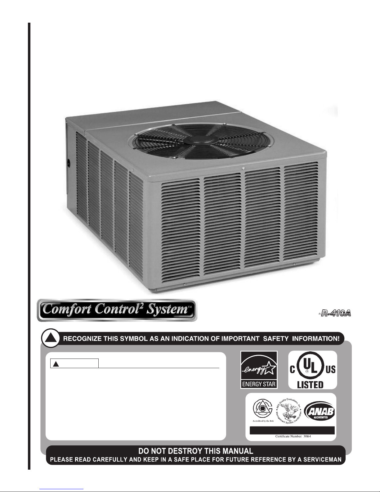
AIR-COOLED CONDENSING UNITS
(-)ASL-JEC 18 SEER EQUIPPED WITH THE COMFORT CONTROL
SYSTEM™ AND FEATURING DUAL DRIVE COMPRESSORS IN
SELECT MODELS
2
[ ] INDICATES METRIC CONVERSIONS
Featuring Industry Standard
R-410A Refrigerant
92-101691-05-06
SUPERSEDES 92-101691-05-05
Page 2

TABLE OF CONTENTS
1.0 SAFETY INFORMATION . . . . . . . . . . . . . . . . . . . . . . . . . . . . . . . . . . . . . . . . . . . . 3
2.0 GENERAL INFORMATION . . . . . . . . . . . . . . . . . . . . . . . . . . . . . . . . . . . . . . . . . . 5
2.1 Checking Product Received . . . . . . . . . . . . . . . . . . . . . . . . . . . . . . . . . . . . 5
2.2 Application . . . . . . . . . . . . . . . . . . . . . . . . . . . . . . . . . . . . . . . . . . . . . . . . . . 5
2.3 Dimensions . . . . . . . . . . . . . . . . . . . . . . . . . . . . . . . . . . . . . . . . . . . . . . . . . 6
2.4 Electrical and Physical Data . . . . . . . . . . . . . . . . . . . . . . . . . . . . . . . . . . . . 6
2.5 Proper Installation . . . . . . . . . . . . . . . . . . . . . . . . . . . . . . . . . . . . . . . . . . . . 7
3.0 LOCATING UNIT . . . . . . . . . . . . . . . . . . . . . . . . . . . . . . . . . . . . . . . . . . . . . . . . . . 7
3.1 Corrosive Environment . . . . . . . . . . . . . . . . . . . . . . . . . . . . . . . . . . . . . . . . 7
.2 Condenser Location. . . . . . . . . . . . . . . . . . . . . . . . . . . . . . . . . . . . . . . . . . . 7
3
3.3 Operational Issues. . . . . . . . . . . . . . . . . . . . . . . . . . . . . . . . . . . . . . . . . . . . 8
3.4 For Condensers With Space Limitations . . . . . . . . . . . . . . . . . . . . . . . . . . . 8
3.5 Customer Satisfaction Issues . . . . . . . . . . . . . . . . . . . . . . . . . . . . . . . . . . . 8
3.6 Unit Mounting. . . . . . . . . . . . . . . . . . . . . . . . . . . . . . . . . . . . . . . . . . . . . . . . 8
3.7 Factory-Preferred Tie-Down Method . . . . . . . . . . . . . . . . . . . . . . . . . . . . . . 8
4.0 REFRIGERANT CONNECTIONS . . . . . . . . . . . . . . . . . . . . . . . . . . . . . . . . . . . . . 9
4.1 Tools Required for Installing & Servicing R-410A Models . . . . . . . . . . . . . . 9
4.2 Specifications of R-410A . . . . . . . . . . . . . . . . . . . . . . . . . . . . . . . . . . . . . . 10
4.3 Quick Reference Guide for R-410-A . . . . . . . . . . . . . . . . . . . . . . . . . . . . . 10
5.0 REPLACEMENT UNITS. . . . . . . . . . . . . . . . . . . . . . . . . . . . . . . . . . . . . . . . . . . . 11
6.0 INDOOR COIL . . . . . . . . . . . . . . . . . . . . . . . . . . . . . . . . . . . . . . . . . . . . . . . . . . . 11
6.1 Location . . . . . . . . . . . . . . . . . . . . . . . . . . . . . . . . . . . . . . . . . . . . . . . . . . . 11
7.0 INTERCONNECTING TUBING . . . . . . . . . . . . . . . . . . . . . . . . . . . . . . . . . . . . . . 11
7.1 Vapor and Liquid Lines . . . . . . . . . . . . . . . . . . . . . . . . . . . . . . . . . . . . . . . 11
7.2 Maximum Length of Lines . . . . . . . . . . . . . . . . . . . . . . . . . . . . . . . . . . . . . 12
7.3 Outdoor Unit Installed Above or Below Indoor Coil . . . . . . . . . . . . . . . . . . 12
7.4 Tubing Installation . . . . . . . . . . . . . . . . . . . . . . . . . . . . . . . . . . . . . . . . . . . 12
7.5 Tubing Connections. . . . . . . . . . . . . . . . . . . . . . . . . . . . . . . . . . . . . . . . . . 15
7.6 Leak Testing . . . . . . . . . . . . . . . . . . . . . . . . . . . . . . . . . . . . . . . . . . . . . . . 15
8.0 DUAL DRIVE COMPRESSORS. . . . . . . . . . . . . . . . . . . . . . . . . . . . . . . . . . . . . . 16
8.1 Compressor Identification . . . . . . . . . . . . . . . . . . . . . . . . . . . . . . . . . . . . . 16
8.2 Comfort Control
8.3 Comfort Control
9.0 COMPRESSOR CRANKCASE HEAT (CCH) . . . . . . . . . . . . . . . . . . . . . . . . . . . 17
10.0 HARD START COMPONENTS . . . . . . . . . . . . . . . . . . . . . . . . . . . . . . . . . . . . . . 17
11.0 HIGH AND LOW PRESSURE CONTROLS (HPC AND LPC). . . . . . . . . . . . . . . 17
11.1 Evacuation Procedure . . . . . . . . . . . . . . . . . . . . . . . . . . . . . . . . . . . . . . . . 18
12.0 CONDENSING UNITS EQUIPPED WITH THE COMFORT CONTROL
SYSTEM™ . . . . . . . . . . . . . . . . . . . . . . . . . . . . . . . . . . . . . . . . . . . . . . . . . . . . . . 18
12.1 Control Description . . . . . . . . . . . . . . . . . . . . . . . . . . . . . . . . . . . . . . . . . . 18
12.2 Comfort Control
12.3 Comfort Control
12.4 Comfort Control
12.5 Active Compressor Protection Mode . . . . . . . . . . . . . . . . . . . . . . . . . . . . . 22
12.6 Test and Fault Recall Modes . . . . . . . . . . . . . . . . . . . . . . . . . . . . . . . . . . . 24
12.7 ICC Diagnostic Codes . . . . . . . . . . . . . . . . . . . . . . . . . . . . . . . . . . . . . . . . 26
12.8 Conventional 24VAC Thermostat Control Wiring . . . . . . . . . . . . . . . . . . . 29
12.9 Typical Non-Communicating Thermostat Wiring Diagrams. . . . . . . . . . . . 30
12.10 Diagnostic Codes in Dual Drive Condensing Units With Conventional
Thermostat Wiring . . . . . . . . . . . . . . . . . . . . . . . . . . . . . . . . . . . . . . . . . . . 31
12.11 ICC Control Operation with Conventional Thermostat Wiring . . . . . . . . . . 31
12.12 Active Compressor Protection Mode . . . . . . . . . . . . . . . . . . . . . . . . . . . . . 32
12.13 Test and Fault Recall Modes . . . . . . . . . . . . . . . . . . . . . . . . . . . . . . . . . . . 34
13.0 ELECTRICAL WIRING. . . . . . . . . . . . . . . . . . . . . . . . . . . . . . . . . . . . . . . . . . . . . 35
13.1 Power Wiring . . . . . . . . . . . . . . . . . . . . . . . . . . . . . . . . . . . . . . . . . . . . . . . 35
13.2 Grounding . . . . . . . . . . . . . . . . . . . . . . . . . . . . . . . . . . . . . . . . . . . . . . . . . 36
13.3 Control Wiring . . . . . . . . . . . . . . . . . . . . . . . . . . . . . . . . . . . . . . . . . . . . . . 36
14.0 START-UP AND PERFORMANCE . . . . . . . . . . . . . . . . . . . . . . . . . . . . . . . . . . . 36
15.0 CHECKING AIRFLOW . . . . . . . . . . . . . . . . . . . . . . . . . . . . . . . . . . . . . . . . . . . . . 36
16.0 CHECKING REFRIGERANT CHARGE . . . . . . . . . . . . . . . . . . . . . . . . . . . . . . . . 37
16.1 Charging Units With R-410A Refrigerant. . . . . . . . . . . . . . . . . . . . . . . . . . 37
16.2 Charging By Liquid Pressure . . . . . . . . . . . . . . . . . . . . . . . . . . . . . . . . . . . 37
16.3 Charging By Weight. . . . . . . . . . . . . . . . . . . . . . . . . . . . . . . . . . . . . . . . . . 37
16.4 Final Leak Testing . . . . . . . . . . . . . . . . . . . . . . . . . . . . . . . . . . . . . . . . . . . 38
17.0 ACCESSORIES . . . . . . . . . . . . . . . . . . . . . . . . . . . . . . . . . . . . . . . . . . . . . . . . . . 38
17.1 Remote Outdoor Temperature Model . . . . . . . . . . . . . . . . . . . . . . . . . . . . 38
17.2 RXME-A02 Communicating 2 Wire Kit . . . . . . . . . . . . . . . . . . . . . . . . . . . 38
18.0 TROUBLESHOOTING . . . . . . . . . . . . . . . . . . . . . . . . . . . . . . . . . . . . . . . . . . . . . 38
18.1 Comfort Control
18.2 Replacement of Comfort Control
18.3 Electrical Checks Flow Chart. . . . . . . . . . . . . . . . . . . . . . . . . . . . . . . . . . . 40
18.4 Cooling Mechanical Checks Flow Chart . . . . . . . . . . . . . . . . . . . . . . . . . . 41
18.5 General Trouble Shooting Chart . . . . . . . . . . . . . . . . . . . . . . . . . . . . . . . . 42
18.6 Service Analyzer Charts . . . . . . . . . . . . . . . . . . . . . . . . . . . . . . . . . . . . 43-47
18.7 Subcooling Calculation . . . . . . . . . . . . . . . . . . . . . . . . . . . . . . . . . . . . . . . 48
19.0 WIRING DIAGRAMS. . . . . . . . . . . . . . . . . . . . . . . . . . . . . . . . . . . . . . . . . . . . 49-50
2
System™ Control Identification . . . . . . . . . . . . . . . . . . . 16
2
System™ Control Operation . . . . . . . . . . . . . . . . . . . . . 17
2
2
Control Wiring . . . . . . . . . . . . . . . . . . . . . . . . . . . . . . . . 20
2
Diagnostic Codes in Dual Drive . . . . . . . . . . . . . . . . . . . 20
2
ICC Control Operation . . . . . . . . . . . . . . . . . . . . . . . . . . 21
2
System™ System Initial Startup . . . . . . . . . . . . . . . . . . 38
2
System™ Control Board . . . . . . . . . . . 39
2
Page 3
1.0 SAFETY INFORMATION
WARNING
!
THESE INSTRUCTIONS ARE INTENDED AS AN AID TO QUALIFIED, LICENSED
SERVICE PERSONNEL FOR PROPER INSTALLATION, ADJUSTMENT AND
OPERATION OF THIS UNIT. READ THESE INSTRUCTIONS THOROUGHLY
BEFORE ATTEMPTING INSTALLATION OR OPERATION. FAILURE TO FOLLOW THESE INSTRUCTIONS MAY RESULT IN IMPROPER INSTALLATION,
ADJUSTMENT, SERVICE OR MAINTENANCE POSSIBLY RESULTING IN FIRE,
ELECTRICAL SHOCK, PROPERTY DAMAGE, PERSONAL INJURY OR DEATH.
WARNING
!
THE MANUFACTURER’S WARRANTY DOES NOT COVER ANY DAMAGE OR
DEFECT TO THE AIR CONDITIONER CAUSED BY THE ATTACHMENT OR USE
OF ANY COMPONENTS, ACCESSORIES OR DEVICES (OTHER THAN THOSE
AUTHORIZED BY THE MANUFACTURER) INTO, ONTO OR IN CONJUNCTION
WITH THE AIR CONDITIONER. YOU SHOULD BE AWARE THAT THE USE OF
UNA U THOR I ZED COM P ONEN T S, ACCE S SORI E S O R DEVI C ES MAY
ADVERSELY AFFECT THE OPERATION OF THE AIR CONDITIONER AND MAY
ALSO ENDANGER LIFE AND PROPERTY. THE MANUFACTURER DISCLAIMS
ANY RESPONSIBILITY FOR SUCH LOSS OR INJURY RESULTING FROM THE
USE OF SUCH UNAUTHORIZED COMPONENTS, ACCESSORIES OR DEVICES.
WARNING
!
DISCONNECT ALL POWER TO UNIT BEFORE STARTING MAINTENANCE.
FAILURE TO DO SO CAN CAUS E ELECTRIC AL SHO CK R ESULTIN G IN
SEVERE PERSONAL INJURY OR DEATH.
WARNING
!
DO NOT USE OXYGEN TO PURGE LINES OR PRESSURIZE SYSTEM FOR
LEAK TEST. OXYGE N REAC TS VIOLENTLY WITH OIL, WHI CH CAN
CAUSE AN EXPLOSION RESULTING IN SEVERE PERSONAL INJURY OR
DEATH.
WARNING
!
THE UNIT MUST BE PERMANENTLY GROUNDED. FAILURE TO DO SO
CAN CAUSE ELECTRICAL SHOCK RESULTING IN SEVERE PERSONAL
INJURY OR DEATH.
WARNING
!
TURN OFF ELECTRIC POWER AT THE FUSE BOX OR SERVICE PANEL
BEFORE MAKING ANY ELECTRICAL CONNECTIONS.
ALSO, THE GROUND CONNECTION MUST BE COMPLETED BEFORE
MAKING LINE VOLT AGE CO NNECT IONS. FAILU RE TO DO SO CAN
RESULT IN ELECTRICAL SHOCK, SEVERE PERSONAL INJURY OR
DEATH.
Continued on next page ➜
3
Page 4
!
CAUTION
R-410A systems operate at higher pressures than R-22 systems. Do not use
R-22 service equipment or components on R-410A equipment.
CAUTION
!
Only use evaporators approved for use on R-410A systems. Use of existing
R-22 evaporators can introduce mineral oil to the R-410A refrigerant forming two different liquids and decreasing oil return to the compressor. This
can result in compressor failure.
CAUTION
!
When coil is installed over a finished ceiling and/or living area, it is
rec o m mended t h a t a s econd a r y sheet me t a l conden s ate pan be
constructed and installed under entire unit. Failure to do so can result
in property damage.
CAUTION
!
THE COMPRESSOR HAS AN INTERNAL OVERLOAD PROTECTOR. UNDER
SOME CONDITIONS, IT CAN TAKE UP TO 2 HOURS FOR THIS OVERLOAD
TO RESET. MAKE SURE OVERLOAD HAS HAD TIME TO RESET BEFORE
CONDEMNING THE COMPRESSOR.
CAUTION
!
UNIT MAY START SUDDENLY AND WITHOUT WARNING
Solid red light indicates a thermostat call for unit operation is present at
the ICC control. ICC control will attempt to start unit after short cycle timer
expires or when in Active Protection mode will attempt to restart unit prior
to Lockout mode.
CAUTION
!
UNIT MAY START SUDDENLY AND WITHOUT WARNING
Solid red light indicates a thermostat call for unit operation is present at the
ICC. ICC will attempt to start unit after short cycle timer expires or when in
Active Protection mode will attempt to restart unit prior to Lockout mode.
CAUTION
!
THE TOP OF THE SCROLL COMPRESSOR SHELL IS HOT. TOUCHING THE
COMPRESSOR TOP MAY RESULT IN SERIOUS PERSONAL INJURY.
CAUTION
!
R-410A PRESSURES ARE APPROXIMATELY 60% HIGHER THAN R-22
PRESSURES. USE APPROPRIATE CARE WHEN USING THIS REFRIGERANT. FAILURE TO EXERCISE CARE MAY RESULT IN EQUIPMENT DAMAGE, OR PERSONAL INJURY.
4
Page 5
WARNING
!
TH E MANUFAC TUR ER’S WARRANTY DOES NOT COVER ANY
DA MAGE OR DEFE CT TO THE
AIR CONDITIONER CAUSED BY
THE ATTACHMENT OR USE OF
ANY COM P O NENTS. ACC E SSOR IES OR DEV ICES (OTH ER
THAN THOSE AUTHORIZED BY
THE M A NUFAC T U RER) IN T O,
ONT O OR IN C ONJUN C T ION
WI TH THE AIR CO NDI TIONER.
YOU SHOULD BE AWARE THAT
THE U SE OF UN AUTHO R IZED
COMPONENTS, ACCESSORIES
OR DEVICES MAY ADVERSELY
AFF E C T TH E OPER A T ION
OF THE AIR CONDITIONER AND
MAY AL S O EN DANGE R LI F E
AND PROPERTY. THE MANUFACTUR E R DIS C L AIMS ANY
RES P O NSIBIL I TY FO R SU C H
LO SS OR IN JUR Y RE SULTING
FRO M THE USE OF SUCH
UNAUTHORIZED COMPONENTS,
ACCESSORIES OR DEVICES.
2.0 GENERAL INFORMATION
The (-)ASL-series of condensing units are designed to operate using the Comfort
Control
Comfort Control
Control
• (-)ASL condensing unit equipped with the Comfort Control
• An air handler or furnace equipped with the Comfort Control
•
If your installation does not meet the above requirements, you must use traditional
24VAC controls.
T
and setup using Comfort Control
the Engineering Specification Sheets for complete performance data, thermostat,
and accessory listings.
The information contained in this manual has been prepared to assist in the proper
installation, operation and maintenance of the air conditioning system. Improper
installation, or installation not made in accordance with these instructions, can result
in unsatisfactory operation and/or dangerous conditions (noise and component failure), and can cause the related warranty not to apply.
Read this manual and any instructions packaged with separate equipment required
to make up the system prior to installation. Retain this manual for future reference.
To achieve optimum efficiency and capacity, the indoor cooling coils listed in the
condensing unit specification sheet should be used.
2.1 CHECKING PRODUCT RECEIVED
Upon receiving unit, inspect it for any shipping damage. Claims for damage, either
apparent or concealed, should be filed immediately with the shipping company.
Check condensing unit model number, electrical characteristics and accessories to
determine if they are correct. Check system components (evaporator coil, condensing unit, evaporator blower, etc.) to make sure they are properly matched.
2
System™ or traditional 24VAC controls. These units are equipped with the
2
System™ :
A Comfort Control
his installation instruction manual contains complete instructions for installation
2
. Your installation must have these components to use Comfort
2
System™
2
2
hermostat
t
2
or conventional 24VAC controls. Please refer to
System™
MATCH ALL COMPONENTS:
• OUTDOOR UNIT
• INDOOR COIL/METERING DEVICE
• INDOOR AIR HANDLER/FURNACE
• REFRIGERANT LINES
2.2 APPLICATION
Before specifying any air conditioning equipment, a survey of the structure and a
heat gain calculation must be made. A heat gain calculation begins by measuring
all external surfaces and openings that gain heat from the surrounding air and
quantifying that heat gain. A heat gain calculation also calculates the extra heat
load caused by sunlight and by humidity removal.
Air conditioning systems are sized on the cooling load calculation. There are two
capacities that enable the equipment to provide comfort. The first is sensible capacity.
Sensible heat is the heat energy measured on the dry bulb thermometer as it is
added or removed.
The second form of heat is called latent or hidden heat. This is heat held in the
humidity in the air.
A properly-sized unit removes both forms of heat, producing a comfortable living
space. An oversized system cycles on and off too quickly and does not properly
remove humidity, producing an uncomfortable living space. Select the indoor and
outdoor equipment combination based on the manufacturer’s engineering data.
After the equipment combination has been selected, satisfying both sensible and
latent conditioning requirements, the system must be properly installed. Only then
can the unit provide the comfort the manufacturer intends.
There are several factors that the installers must consider:
• Outdoor unit location • Proper equipment evacuation
• System refrigerant charge • Indoor unit airflow
• Indoor unit blower speed • Supply and return air duct design and sizing
• System air balancing • Diffuser and return air grille location and sizing
5
Page 6
A
IR INLETS
(
LOUVERS)
A
LLOW 120 [305 mm]
M
IN. CLEARANCE
3
SIDES
AIR DISCHARGE
ALLOW 600 [1524 mm] CLEARANCE
ALLOW 240 [610 mm]
ACCESS CLEARANCE
ACCESS
PANEL
L
W
H
ALTERNATE HIGH VOLTAGE
CONNECTION (KNOCKOUT)
1
11
/320[34 mm]
SERVICE
F
ITTINGS
LOW VOLTAGE
CONNECTION
7
/8"
[22 mm]
HIGH VOLTAGE
CONNECTION
1
1
1
/32" [34 mm]
LIQUID LINE
CONNECTION
SERVICE ACCESS
TO ELECTRICAL &
VALVES ALLOW
24" [610 mm]
CLEARANCE
ONE SIDE
2
7
/8" [73 mm] DIA.
ACCESSORY
KNOCKOUTS
VAPOR LINE
CONNECTION
A-00002
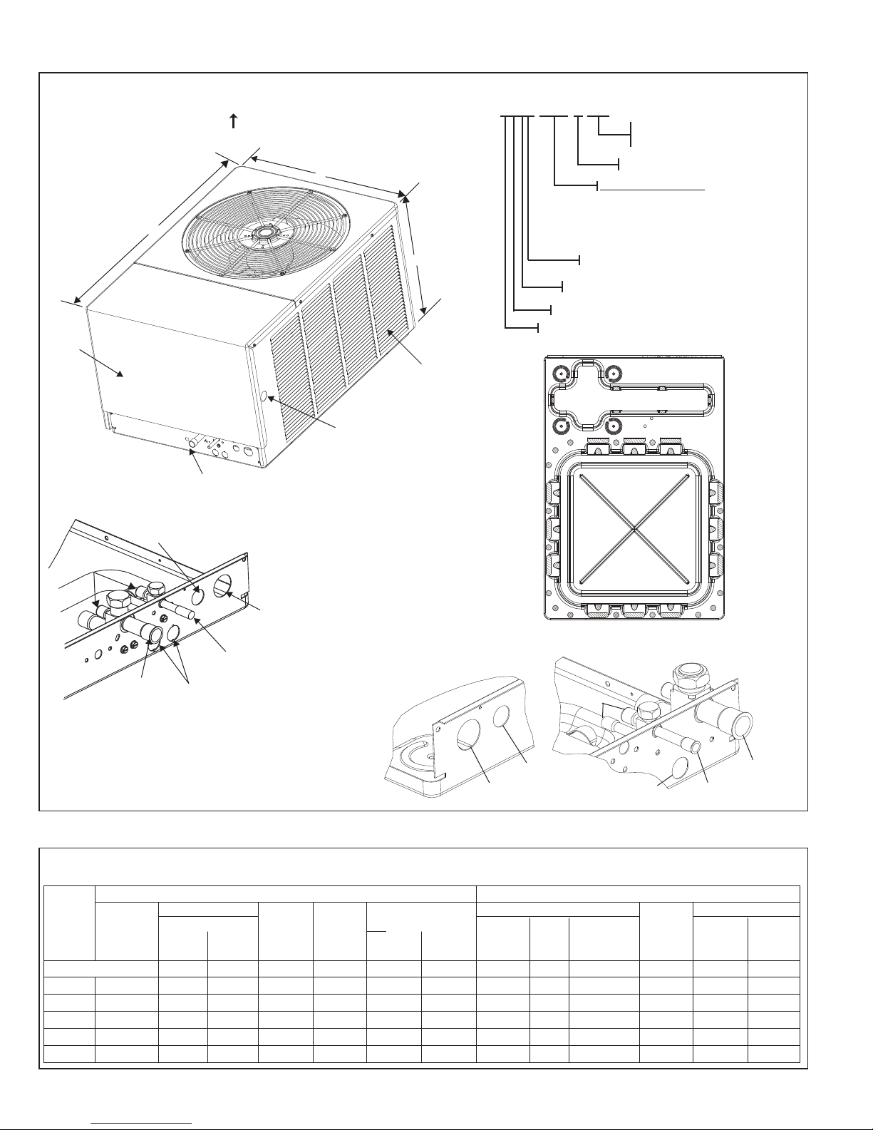
2.3 DIMENSIONS
FIGURE 1
DIMENSIONS AND INSTALLATION CLEARANCES
AIR DISCHARGE
ALLOW 60" [1524 mm] CLEARANCE
ACCESS
PANEL
LLOW 24" [610 mm]
A
ACCESS CLEARANCE
UNIT MODEL NUMBER EXPLANATION
AIR INLETS
(LOUVERS)
ALLOW 6” [152 mm]
MIN. CLEARANCE
3 SIDES
ALTERNATE LINE VOLTAGE
ENTRY (KNOCKOUT)
111⁄32" [34 MM]
CONNECT THE LINE
VOLTAGE CONDUIT TO
THE BOTTOM OF THE
CONTROL BOX
-)ASL – 036 JEC
(
L = DESIGN SERIES (R-410A)
S = 18 SEER
A = REMOTE CONDENSING UNIT
TRADE NAME
BASE PAN
C = EQUIPPED WITH THE
E
COMFORT CONTROL
- 208/230-1-60
J
NOMINAL CAPACITY)
(
024 = 24000 BTU/HR
036 = 36000 BTU/HR
039 = 39000 BTU/HR
048 = 48000 BTU/HR
060 = 60000 BTU/HR
2
SYSTEM™
LINE VOLTAGE
ENTRY
7
⁄8" [22 MM]
LINE VOLTAGE ENTRY
11
⁄32" [34 MM]
1
CONNECT THE LINE
VOLTAGE CONDUIT TO
THE BOTTOM OF THE
CONTROL BOX
SERVICE ACCESS
FOR 024 & 036 MODELS
2.4 ELECTRICAL & PHYSICAL DATA
TABLE 1
(-)ASL-JEC ELECTRICAL DATA
Rev. 2/24/2010
Model
Number
RASL-
Phase
Frequency
(Hz)
Voltage
(Volts)
024JEC 1-60-208/230 10.3/10.3 52 0.5 14/14 20/20 20/20 15.8 [1.47] 1 2500 [1038] 144 [4082] 236 [107] 263.5 [119.5]
036JEC 1-60-208/230 16.7/16.7 82 2.8 24/24 30/30 40/40 23.01 [2.14] 1 3400 [1321] 150 [4252] 250.5 [113.6] 314.5 [142.7]
039JEC 1-60-208/230 17.9/17.9 96 2.8 26/26 30/30 40/40 23 [2.14] 2 3500 [1321] 268 [7598] 326 [147.9] 345 [156.5]
048JEC 1-60-208/230 26.9/26.9 117 2.8 37/37 45/45 60/60 23 [2.14] 2 3500 [1321] 253 [7173] 326 [147.9] 348 [157.9]
060JEC 1-60-208/230 28.2/28.2 146 2.8 39/39 50/50 60/60 23 [2.14] 2 3500 [1321] 241 [6832] 328 [148.8] 346 [156.9]
6
Rated Load
Amperes
ELECTRICAL PHYSICAL
Compressor
(RLA)
Locked
Rotor
Amperes
(LRA)
Fan
Motor
Full Load
Amperes
(FLA)
Minimum
Circuit
Ampacity
Amperes
SERVICE ACCESS
FOR 039, 048 & 060 MODELS
Fuse or HACR
Circuit Breaker
Minimum
Amperes
Maximum
Amperes
HIGH LINE
VOLTAGE 1
Face Area
Sq. Ft. [m
BOTTOM VIEW SHOWING DRAIN OPENINGS
(\\\\\ SHADED AREAS).
SERVICE
FITTING
LOW LINE
VOLTAGE7⁄8"
1
⁄4"
Outdoor Coil Weight
No.
2
]
Rows
CFM [L/s}
LOW LINE
VOLTAGE
7
⁄8"
Refrig.
Per
Circuit
Oz. [g]
LIQUID LINE
CONNECTION
Net
Lbs. [kg]
VAPOR LINE
CONNECTION
Shipping
Lbs. [kg]
Page 7
2.5 PROPER INSTALLATION
Proper sizing and installation of this equipment is critical to achieve optimal performance. Use the information in this Installation Instruction Manual and reference the
applicable Engineering Specification Sheet when installing this product.
IMPORTANT: This product has been designed and manufactured to meet ENERGY STAR
ents. However, proper refrigerant charge and proper airflow are critical to achieve
n
rated capacity and efficiency. Installation of this product should follow the manufacturer’s refrigerant charging and airflow instructions. Failure to confirm proper
charge and airflow may reduce energy efficiency and shorten equipment life.
®
criteria for energy efficiency when matched with appropriate coil compo-
3.0 LOCATING UNIT
3.1 Corrosive Environment
The metal parts of this unit may be subject to rust or deterioration if exposed to a
corrosive environment. This oxidation could shorten the equipment’s useful life.
Corrosive elements include, but are not limited to, salt spray, fog or mist in seacoast
areas, sulphur or chlorine from lawn watering systems, and various chemical contaminants from industries such as paper mills and petroleum refineries.
If the unit is to be installed in an area where contaminants are likely to be a problem, special attention should be given to the equipment location and exposure.
• Avoid having lawn sprinkler heads spray directly on the unit cabinet.
• In coastal areas, locate the unit on the side of the building away from the waterfront.
• Shielding provided by a fence or shrubs may give some protection, but cannot
violate minimum airflow and service access clearances.
• Elevating the unit off its slab or base enough to allow air circulation will help
avoid holding water against the basepan.
Regular maintenance will reduce the build-up of contaminants and help to protect
the unit’s finish.
WARNING
!
DIS C O NNECT AL L POWE R T O UNIT B E FORE ST A RTING
MAINTENANCE. FAILURE TO DO SO CAN CAUSE ELECTRICAL SHOCK
RESULTING IN SEVERE PERSONAL INJURY OR DEATH.
• Frequent washing of the cabinet, fan blade and coil with fresh water will remove
most of the salt or other contaminants that build up on the unit.
• Regular cleaning and waxing of the cabinet with a good automobile polish will
provide some protection.
• A good liquid cleaner may be used several times a year to remove matter that
will not wash off with water.
Several different types of protective coatings are offered in some areas. These
coatings may provide some benefit, but the effectiveness of such coating materials
cannot be verified by the equipment manufacturer.
3.2 CONDENSER LOCATION
Consult local and national building codes and ordinances for special installation
requirements. Following location information will provide longer life and simplified
servicing of the outdoor condenser.
NOTE: These units must be installed outdoors. No ductwork can be attached, or
other modifications made, to the discharge grille. Modifications will affect performance or operation.
7
Page 8

3.3 Operational Issues
• IMPORTANT: Locate the unit in a manner that will not prevent, impair or com-
promise the performance of other equipment horizontally installed in proximity
to the unit. Maintain all required minimum distances to gas and electric meters,
dryer vents, exhaust and inlet openings. In the absence of National Codes, or
anufacturers’ recommendations, local code recommendations and require-
m
ments will take precedence.
• Refrigerant piping and wiring should be properly sized and kept as short as
possible to avoid capacity losses and increased operating costs.
• Locate the unit where water run off will not create a problem with the equipment. Position the unit away from the drip edge of the roof whenever possible.
Units are weatherized, but can be affected by the following:
o Water pouring into the unit from the junction of rooflines, without protective
guttering. Large volumes of water entering the heat pump while in operation
can impact fan blade or motor life, and coil damage may occur to a heat
pump if moisture cannot drain from the unit under freezing conditions.
o Freezing moisture, or sleeting conditions, can cause the cabinet to ice-over
prematurely and prevent heat pump operation, requiring backup heat, which
generally results in less economical operation.
• Closely follow clearance recommendations on Page 6.
o 24” to the service panel access
o 60” above heat pump fan discharge (unit top) to prevent recirculation
o 6” to heat pump coil grille air inlets
3.4 For Units With Space Limitations
FOR CONDENSERS WITH SPACE LIMITATIONS
In the event that a space limitation exists, we will permit the following clearances:
Single Unit Applications: Clearances below 6 inches will reduce unit capacity and
efficiency. Do not reduce the 60-inch discharge, or the 24-inch service clearances.
Multiple Unit Applications: When multiple condenser grille sides are aligned, a 6inch per unit clearance is recommended, for a total of 12” between two units. Two
combined clearances below 12 inches will reduce capacity and efficiency. Do not
reduce the 60-inch discharge, or 24-inch service, clearances.
3.5 Customer Satisfaction Issues
• The condensing unit should be located away from the living, sleeping and
recreational spaces of the owner and those spaces on adjoining property.
• To prevent noise transmission, the mounting pad for the outdoor unit should not
be connected to the structure, and should be located sufficient distance above
grade to prevent ground water from entering the unit.
3.6 Unit Mounting
If elevating the condensing unit, either on a flat roof or on a slab, observe the
following guidelines.
• The base pan provided elevates the heat pump 3/4” above the base pad.
• If elevating a unit on a flat roof, use 4” x 4” (or equivalent) stringers positioned
to distribute unit weight evenly and prevent noise and vibration (see Figure 2).
NOTE: Do not block drain openings shown in Figure 1.
3.7 Factory-Preferred Tie-Down Method for Outdoor Units
IMPORTANT: The Manufacturer approved/recommended method is a guide to securing equipment for wind and seismic loads. Other methods might provide the same
result, but the Manufacturer method is the only one endorsed by Manufacturer for
securing equipment where wind or earthquake damage can occur. Additional information is available in the PTS (Product Technical Support) section of the Manufacturer
website Rheemote.net and can be found as a listing under each outdoor model. If you
do not have access to this site, your Distributor can offer assistance.
8
Page 9
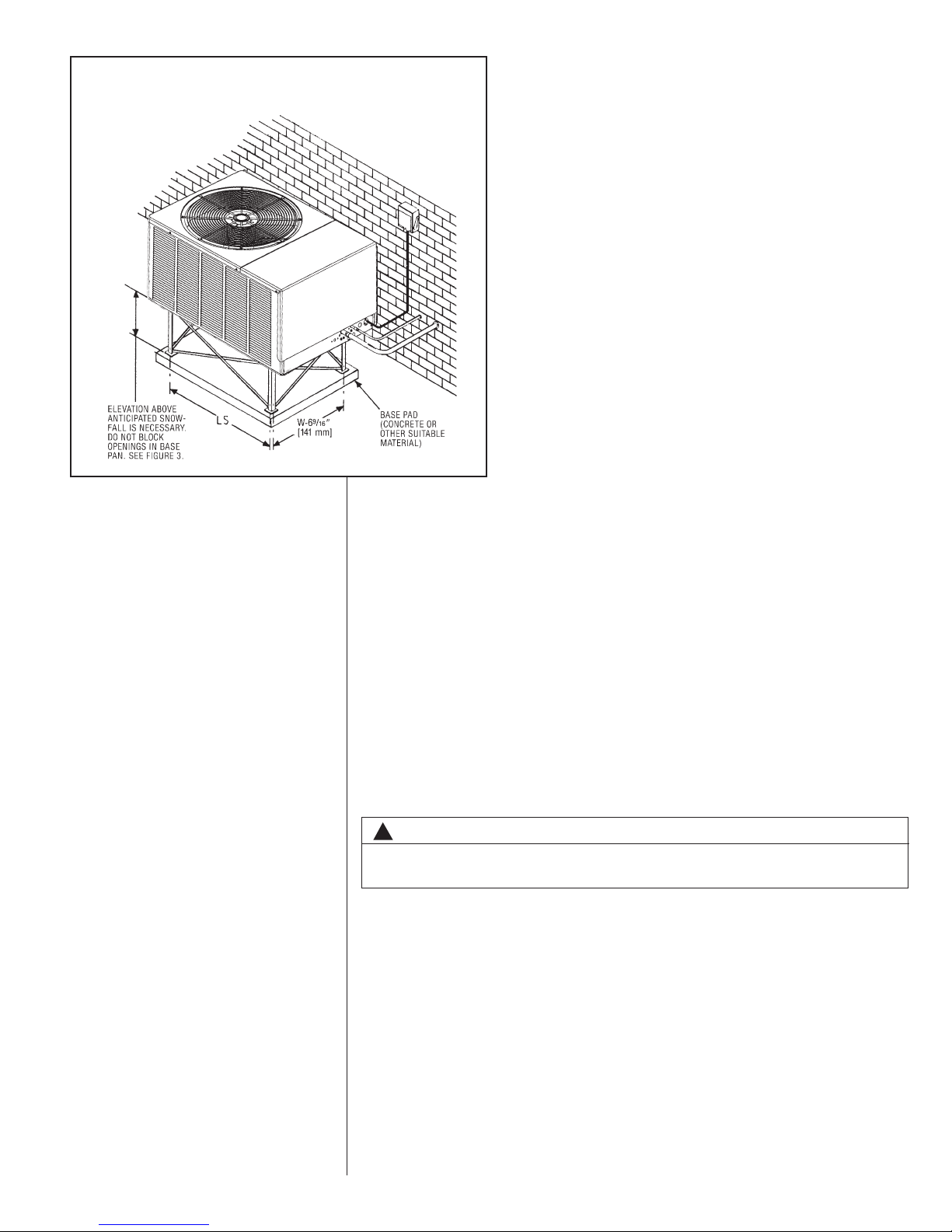
FIGURE 2
ECOMMENDED ELEVATED INSTALLATION
R
4.0 REFRIGERANT CONNECTIONS
All units are factory charged with Refrigerant 410A. All models are supplied with
service valves. Keep tube ends sealed until connection is to be made to prevent
system contamination.
4.1 Tools Required For Installing & Servicing R-410A Models
Manifold Sets:
-Up to 800 PSIG High side
-Up to 250 PSIG Low Side
-550 PSIG Low Side Retard
Manifold Hoses:
-Service Pressure Rating of 800 PSIG
Recovery Cylinders:
-400 PSIG Pressure Rating
-Dept. of Transportation 4BA400 or BW400
!
CAUTION
R-410A systems operate at higher pressures than R-22 systems. Do not use
R-22 service equipment or components on R-410A equipment.
9
Page 10

IMPORTANT: The Rheem approved/recommended method is a guide to securing
equipment for wind and seismic loads. Other methods might provide the same result,
but the Rheem method is the only one endorsed by Rheem for securing equipment
where wind or earthquake damage can occur. Additional information is available in
the PTS (Product Technical Support) section of the Rheem website Rheemote.net
and can be found as a listing under each outdoor model. If you do not have access
to this site, your Distributor can offer assistance.
4.2 Specifications of R-410A:
Application: R-410A is not a drop-in replacement for R-22; equipment designs
must accommodate its higher pressures. It cannot be retrofitted into R-22 heat
pumps.
Physical Properties: R-410A has an atmospheric boiling point of -62.9°F and its
saturation pressure at 77°F is 224.5 psig.
Composition: R-410A is an azeotropic mixture of 50% by weight difluoromethane
(HFC-32) and 50% by weight pentafluoroethane (HFC-125).
Pressure: The pressure of R-410A is approximately 60% (1.6 times) greater
than R-22. Recovery and recycle equipment, pumps, hoses and the like need to
have design pressure ratings appropriate for R-410A. Manifold sets need to range
up to 800 psig high-side and 250 psig low-side with a 550 psig low-side retard.
Hoses need to have a service pressure rating of 800 psig. Recovery cylinders need
to have a 400 psig service pressure rating. DOT 4BA400 or DOT BW400.
Combustibility: At pressures above 1 atmosphere, mixture of R-410A and air can
become combustible. R-410A and air should never be mixed in tanks or supply
lines, or be allowed to accumulate in storage tanks. Leak checking should
never be done with a mixture of R-410A and air. Leak checking can be per-
formed safely with nitrogen or a mixture of R-410A and nitrogen.
4.3 Quick Reference Guide For R-410A
• R-410A refrigerant operates at approximately 60% higher pressure (1.6 times)
than R-22. Ensure that servicing equipment is designed to operate with R-410A.
• R-410A refrigerant cylinders are pink in color.
• R-410A, as with other HFC’s is only compatible with POE oils.
• Vacuum pumps will not remove moisture from oil.
• R-410A systems are to be charged with liquid refrigerants. Prior to March 1999,
R-410A refrigerant cylinders had a dip tube. These cylinders should be kept
upright for equipment charging. Post March 1999 cylinders do not have a dip tube
and should be inverted to ensure liquid charging of the equipment.
• Do not install a suction line filter drier in the liquid line.
• A liquid line filter drier is standard on every unit. Only manufacturer approved liquid line filter driers can be used. These are Sporlan (CW083S) and Alco
(80K083S) driers. These filter driers are rated for minimum working pressure of
600 psig.
• Desiccant (drying agent) must be compatible for POE oils and R-410A.
10
Page 11

5.0 REPLACEMENT UNITS
To prevent failure of a new condensing unit, the existing evaporator tubing system
must be correctly sized and cleaned or replaced. Care must be exercised that the
expansion device is not plugged. For new and replacement units, a liquid line filter
drier should be installed and refrigerant tubing should be properly sized. Test the oil
for acid. If positive, a suction line filter drier is mandatory.
IMPORTANT: WHEN REPLACING AN R-22 UNIT WITH AN R-410A UNIT,
EITHER REPLACE THE LINE SET OR ENSURE THAT THE EXISTING LINE SET
IS THOROUGHLY CLEANED OF ANY OLD OIL OR DEBRIS.
6.0 INDOOR COIL
REFER TO INDOOR COIL MANUFACTURER’S INSTALLATION INSTRUCTIONS.
IMPORTANT: The manufacturer is not responsible for the performance and opera-
tion of a mismatched system, or for a match listed with another manufacturer’s coil.
NOTE: All (-)ASL units must be installed with a TXV Evaporator.
CAUTION
!
Only use evaporators approved for use on R-410A systems. Use of existing R-22
evaporators can introduce mineral oil to the R-410A refrigerant forming two different liquids and decreasing oil return to the compressor. This can result in compressor failure.
The thermostatic expansion valve is specifically designed to operate with R-410A.
DO NOT use an R-22 TXV or evaporator. The existing evaporator must be
replaced with the factory specified TXV evaporator specifically designed for
R-410A.
6.1 Location
Do not install the indoor coil in the return duct system of a gas or oil furnace.
Provide a service inlet to the coil for inspection and cleaning. Keep the coil pitched
toward the drain connection.
CAUTION
!
Whe n coil i s ins t alled over a finis hed ce i ling a nd/or livin g area , it is
rec o m mended that a seconda r y shee t metal c ondens a te pan b e
construct ed and in stalled under entire unit. Failure to do so ca n result
in property damage.
7.0 INTERCONNECTING TUBING
7.1 Vapor and Liquid Lines
Keep all lines sealed until connection is made.
Make connections at the indoor coil first.
Refer to Line Size Information in Tables 3, 4, 5 and 6 for correct size and multipliers
to be used to determine capacity for various vapor line diameters and lengths of run.
The losses due to the lines being exposed to outdoor conditions are not included.
The factory refrigeration charge in the outdoor unit is sufficient for 15 feet of interconnecting lines. The factory refrigeration charge in the outdoor unit is sufficient for
the unit and 15 feet of standard size interconnecting liquid and vapor lines. For different lengths, adjust the charge as indicated below.
1/4” ± .3 oz. per foot
5/16” ± .4 oz. per foot
3/8” ± .6 oz. per foot
1/2” ± 1.2 oz. per foot
11
Page 12

TABLE 3
APOR LINE CAPACITY MULTIPLIER
V
(-)ASL
Unit Vapor Line
Connection Size
(inches I.D.) [mm]
Vapor Line Run
Feet [m]
25‘ [7.62]
50’ [15.24]
75’ [22.86]
100’ [30.48]
125’ [38.10]
150’ [45.72]
NOTES:
1. Do NOT exceed the limits in the liquid and suction line sizing charts.
2. Do NOT use 7/8 OD suction lines in 2 or 4-ton applications.
3. Do NOT use 1-1/8 OD suction line in ANY application.
4. Line sets over 75 feet MUST use the optional suction line.
Opt.
Std.
Opt.
Std.
Opt.
Std.
Opt.
Std.
Opt.
Std.
Opt.
Std.
024
3/4” [19.05] I.D.
Sweat
5/8” [15.88]
Optional
3/4” [19.05]
Standard
1.00 0.99 0.99 0.98 0.99
1.00 1.00 1.00 1.00 1.00
0.98 0.98 0.97 0.96 0.98
1.00 1.00 0.99 0.99 0.99
0.98 0.96 0.96 0.94 0.96
1.00 0.99 0.99 0.98 0.99
0.98 0.95 0.95 0.92 0.95
N/A N/A N/A N/A N/A
0.96 0.94 0.93 0.90 0.94
N/A N/A N/A N/A N/A
0.96 0.92 0.91 0.88 0.93
N/A N/A N/A N/A N/A
036 039 048 060
3/4” [19.05] I.D.
Sweat
Vapor Line Diameter (inches O.D.) [mm]
5/8” [15.88]
Optional
3/4” [19.05]
Standard
3/4” [19.05] I.D.
Sweat
5/8” [15.88]
Optional
3/4” [19.05]
Standard
3/4” [19.05] I.D.
Sweat
5/8” [15.88]
Optional
3/4” [19.05]
Standard
7/8” [22.23] I.D.
Sweat
3/4” [19.05]
Optional
7/8” [22.23]
Standard
7.2 Maximum Length of Lines
The maximum length of interconnecting line is 150 feet. Always use the shortest
length possible with a minimum number of bends. Additional compressor oil is not
required for any length up to 150 feet.
NOTE: Excessively long refrigerant lines cause loss of equipment capacity.
7.3 Outdoor Unit Installed Above or Below Indoor Coil
Use the following guidelines when installing the unit:
1. Expansion Valve Coil:
a. The vertical separation cannot exceed the value in Tables 4, 5, and 6.
b. No changes are required for expansion valve coils.
2. It is recommended to use the smallest liquid line size permitted to minimize the
system charge.
3. Tables 4, 5, and 6 may be used for sizing horizontal runs.
7.4 Tubing Installation
Observe the following when installing correctly sized type “L” refrigerant tubing
between the condensing unit and evaporator coil:
• If a portion of the liquid line passes through a hot area where liquid refrigerant
can be heated to form vapor, insulating the liquid line is required.
• Use clean, dehydrated, sealed refrigeration grade tubing.
• Always keep tubing sealed until tubing is in place and connections are to be
made.
• Blow out the liquid and vapor lines with dry nitrogen before connecting to the
outdoor unit and indoor coil. Any debris in the line set will end up plugging the
expansion device.
• As an added precaution, a high quality filter drier is standard on R-410A units.
• Do not allow the vapor line and liquid line to be in contact with each other. This
causes an undesirable heat transfer resulting in capacity loss and increased
power consumption. The vapor line must be insulated.
• If tubing has been cut, make sure ends are deburred while holding in a position
to prevent chips from falling into tubing. Burrs such as those caused by tubing
cutters can affect performance dramatically, particularly on small liquid line
sizes.
12
Page 13

TABLE 4
(-)ASL LIQUID LINE SIZING
IQUID LINE SIZE - OUTDOOR UNIT ABOVE INDOOR COIL
L
Liquid Line Size
R-410A
System
Capacity
Model
-024 3/8” [9.53] 5/16” [7.93] 000000
-036 3/8” [9.53] 3/8” [9.52]* 00 0000
-039 3/8” [9.53] 3/8” [9.52] 00 0000
-048 3/8” [9.53]
-060 3/8” [9.53]
NOTES: N/A = Application Not Recommended
*Standard Line Size
LIQUID LINE SIZE - OUTDOOR UNIT BELOW INDOOR COIL
R-410A
System
Capacity
Model
-024 3/8” [9.53] 5/16” [7.93] 25 [14.33] 44 [13.41] 40 [12.19] 36 [10.97] 30 [9.14] 24 [7.32]
-036 3/8” [9.53] 3/8” [9.52]* 12 [3.66] 9 [2.74] N/A N/A N/A N/A
-039 3/8” [9.53] 3/8” [9.52] 18 [5.49] 17 [5.18] 15 [4.57] 13 [3.96] 12 [3.66] 10 [3.05]
-048 3/8” [9.53] 3/8” [9.52] 25 [11.89] 36 [10.97] 34 [10.36] 32 [9.75] 29 [8.84] 23 [7.01]
-060 3/8” [9.53]
NOTES: N/A = Application Not Recommended
*Standard Line Size
Line Size
Connection
Size (Inch
I.D.) [mm]
Line Size
Connection
Size (Inch
I.D.) [mm]
Line Size
(Inch O.D.)
[mm]
Outdoor Unit Above Indoor Coil (Cooling Only - Does not apply to Heat Pumps)
Total Equivalent Length - Feet [m]
25 [7.62] 50 [15.24] 75 [22.86] 100 [30.48] 125 [38.1] 150 [45.72]
Minimum Vertical Separation - Feet [m]
1/4” [6.35]* 0010 [3.05] 34 [10.36] 58 [17.68] 82 [24.99]
3/8” [9.52] 000000
5/16” [7.93] 006 [1.83] 14 [4.27] 21 [6.40] 28 [8.53]
1/2” [12.70] 000000
5/16” [7.93]* 000010 [3.05] 24 [7.32]
1/2” [12.70] 000000
5/16” [7.93]* 00018 [5.49] 40 [12.19] 62 [18.90]
3/8” [9.52] 000000
1/2” [12.70] 000000
3/8” [9.52]* 000000
1/2” [12.70] 000000
Liquid Line Size
Line Size
(Inch O.D.)
[mm]
25 [7.62] 50 [15.24] 75 [22.86] 100 [30.48] 125 [38.1] 150 [45.72]
Outdoor Unit Below Indoor Coil
Total Equivalent Length - Feet [m]
Maximum Vertical Separation - Feet [m]**
1/4” [6.35]* 25 [11.28] 13 [3.96] N/A N/A N/A N/A
3/8” [9.52] 25 [15.24] 48 [14.63] 47 [14.33] 46 [14.02] 45 [13.72] 43 [13.11]
5/16” [7.93] N/A N/A N/A N/A N/A N/A
1/2” [12.70] 14 [4.27] 13 [3.96] 13 [3.96] 12 [3.66] 12 [3.66] 11 [3.35]
5/16” [7.93]* 15 [4.57] 11 [3.35] N/A N/A N/A N/A
1/2” [12.70] 20 [6.10] 19 [5.79] 19 [5.79] 19 [5.79] 18 [5.49] 18 [5.49]
5/16” [7.93]* 25 [10.36] 24 [7.32] N/A N/A N/A N/A
1/2” [12.70] 25 [12.50] 40 [12.19] 40 [12.19] 39 [11.89] 39 [11.89] 38 [11.58]
3/8” [9.52]* 25 [11.28] 33 [10.06] 30 [9.14] 25 [7.62] 15 [4.57] N/A
1/2” [12.70] 25 [11.89] 39 [11.89] 38 [11.58] 37 [11.28] 37 [11.28] 36 [10.97]
**Maximum vertical separation listed in table can be exceeded if system is charged to 8°-10°F
liquid subcooling level at the indoor coil. A gauge port must be added to the liquid line near the
indoor coil to measure subcooling at that point.
13
Page 14

ABLE 5
T
-)ASL SUCTION LINE SIZING
(
UCTION LINE SIZE - OUTDOOR UNIT ABOVE INDOOR COIL
S
R-410A
System
Capacity
Model
Line Size
Connection
Size (Inch
I.D.) [mm]
Line Size
(Inch O.D.)
[mm]
Outdoor Unit ABOVE Indoor Coil (Cooling Only - Does not apply to Heat Pumps)
Total Equivalent Length - Feet [m]
Suction Line Size
25 [7.62] 50 [15.24] 75 [22.86] 100 [30.48] 125 [38.1] 150 [45.72]
5/8” [15.88] Same as Liquid Line Size Table
-024 3/4” [19.05] 3/4” [19.05]* NA
7/8” [22.23] NA
5/8” [15.88] Same as Liquid Line Size Table
-036 & -039 3/4” [19.05] 3/4” [19.05]* NA
7/8” [22.23] NA
5/8” [15.88] Same as Liquid Line Size Table
-048 7/8” [22.22] 3/4” [19.05]* Same as Liquid Line Size Table
7/8” [22.23] NA
3/4” [19.05] Same as Liquid Line Size Table
-060 7/8” [22.22] 7/8” [22.23]* NA
1-1/8” [28.58] NA
NOTES: Using suction line larger than shown in chart will result in poor oil return.
N/A = Application Not Recommended
*Standard Line Size
UCTION LINE SIZE - OUTDOOR UNIT BELOW INDOOR COIL
S
R-410A
System
Capacity
Model
Line Size
Connection
Size
(Inch I.D.)
[mm]
Line Size
(Inch O.D.)
[mm]
Outdoor Unit BELOW Indoor Coil (Cooling Only - Does not apply to Heat Pumps)
Total Equivalent Length - Feet [m]
Suction Line Size
25 [7.62] 50 [15.24] 75 [22.86] 100 [30.48] 125 [38.1] 150 [45.72]
5/8” [15.88] Same as Liquid Line Size Table
-024 3/4” [19.05] 3/4” [19.05]* Same as Liquid Line Size Table NA
7/8” [22.23] NA
5/8” [15.88] Same as Liquid Line Size Table
-036 & -039 3/4” [19.05] 3/4” [19.05]* Same as Liquid Line Size Table
7/8” [22.23] NA
5/8” [15.88] Same as Liquid Line Size Table
-048 7/8” [22.22] 3/4” [19.05]* Same as Liquid Line Size Table
7/8” [22.23] Same as Liquid Line Size Table NA
3/4” [19.05] Same as Liquid Line Size Table
-060 7/8” [22.22] 7/8” [22.23]* Same as Liquid Line Size Table
1-1/8” [28.58] NA
NOTES: Using suction line larger than shown in chart will result in poor oil return.
N/A = Application Not Recommended
*Standard Line Size
14
Page 15

• For best operation, keep tubing run as short as possible with a minimum num-
ber of elbows or bends.
• Locations where the tubing will be exposed to mechanical damage should be
avoided. If it is necessary to use such locations, the copper tubing should be
oused to prevent damage.
h
• If tubing is to be run underground, it must be run in a sealed watertight chase.
• Use care in routing tubing and do not kink or twist. Use a good tubing bender
n the vapor line to prevent kinking.
o
• Route the tubing using temporary hangers, then straighten the tubing and
install permanent hangers. Line must be adequately supported.
The vapor line must be insulated to prevent dripping (sweating) and prevent
•
performance losses. Armaflex and Rubatex are satisfactory insulations for this
purpose. Use 1/2” minimum insulation thickness, additional insulation may be
required for long runs.
• Check Table 3 for the correct vapor line size. Check Table 4 for the correct liq-
uid line size.
7.5 Tubing Connections
Indoor coils have only a holding charge of dry nitrogen. Keep all tube ends sealed
until connections are to be made.
• Use type “L” copper refrigeration tubing. Braze the connections with the follow-
ing alloys:
– copper to copper - 5%
– Silver alloy (no flux)
– copper to steel or brass - 35%
– silver alloy (with flux)
• Be certain both refrigerant shutoff valves at the outdoor unit are closed.
• Clean the inside of the fittings and outside of the tubing with steel wool or sand
cloth before soldering. Always keep chips, steel wool, dirt, etc., out of the inside
when cleaning.
• Assemble tubing part way into fitting. Apply flux all around the outside of the
tubing and push tubing into stop. This procedure will keep the flux from getting
inside the system.
• Remove the cap and schrader core from service port to protect seals from heat
damage.
• Use an appropriate heatsink material around the copper stub and the service
valves before applying heat.
• IMPORTANT: Do not braze any fitting with the TEV sensing bulb attached.
• Braze the tubing between the outdoor unit and indoor coil. Flow dry nitrogen
into a service port and through the tubing while brazing.
• After brazing – use an appropriate heatsink material to cool the joint and
remove any flux residue.
• The service valves are not backseating valves. To open the valves, remove the
valve cap with an adjustable wrench. Insert a 3/16” or 5/16” hex wrench into the
stem. Back out counterclockwise.
• Replace the valve cap finger tight then tighten an additional 1/2 hex flat for a
metal-to-metal seal.
7.6 Leak Testing
• Pressurize line set and coil through service fittings with dry nitrogen to 150
PSIG maximum. Leak test all joints using liquid detergent. If a leak is found,
recover pressure and repair.
WARNING
!
DO NOT USE OXYGEN TO PURGE LINES OR PRESSURIZE SYSTEM FOR
LEAK TEST. OXYGE N REAC TS VIOLENTLY WITH OIL, WHI CH CAN
CAUSE AN EXPLOSION RESULTING IN SEVERE PERSONAL INJURY OR
DEATH.
15
Page 16

8.0 DUAL DRIVE COMPRESSORS
The -039, -048, & -060 condensing units contain two compressors to deliver maximum efficiency and comfort. The Dual Drive Compressors are sized to increase run
times at first stage operation (partial capacity). When additional capacity is needed,
a two stage thermostat energizes both compressors to deliver full rated capacity.
8.1 Compressor Identification
The individual compressors are identified as Compressor A and Compressor B.
When facing the access panel, Compressor A is on the left and Compressor B is on
the right. (See Figure 4.)
FIGURE 4
DUAL DRIVE COMPRESSORS
COMPRESSOR A COMPRESSOR B
8.2 Comfort Control2System™ Control Identification
The Dual Drive condensing units use one (1) serial communicating control per compressor. There is a label in the control box that identifies each control/compressor
combination. When facing the access panel, Compressor A is controlled by the lefthand board and Compressor B is controlled by the right-hand board.
FIGURE 5
16
Page 17

8.3 Comfort Control2System™ Control Operation
A Dual Drive unit has two controls instead of a single control. The controls are the
same as any residential communicating control except the secondary control dipswitches (SW5) should be in the off position. Therefore, the features such as fault
recall and the operation of the test button are the same as any JEC control.
The two controls are identical and interchangeable, but the memory cards that
attach to the controls are not interchangeable. This allows the controls to be
swapped for troubleshooting if one of the controls is suspected of being defective. If
the controls are swapped, it is important to keep the memory cards in the proper
locations. Do not cut the tethers on the memory cards!
8.4 Lead/Lag
Tandem compressor ASL units now have a Lead/Lag functionality built into the control software. The purpose of Lead/Lag is to average the runtime of the compressors to give the homeowner the greatest compressor life possible. Upon receiving a
first stage call, the primary compressor control (the control on the left as you face
the control box) will alternate which compressor services the call. An example of
Lead/Lag is: if compressor A is energized on one first stage call, compressor B
would normally service the next first stage call.
9.0 COMPRESSOR CRANKCASE HEAT (CCH)
CCH is standard on these models due to refrigerant migration during the off cycle
that can result in a noisy start up.
Crankcase Heater Operation:
Supplemental Crankcase heat is required to prevent refrigerant migration in systems with relatively high system refrigerant charges. Each Dual Drive compressor
has its own crankcase heater.
2
The crankcase heater control is integrated into the Comfort Control
is designed for maximum energy savings.
Summary of operation:
• The crankcase heater is off whenever the compressor is running.
• Once the compressor turns off, the crankcase heater control (CCH) begins the
two-hour timer countdown.
• If the compressor stays off for two hours, the CCH turns on the crankcase heater.
All heaters are located on the lower half of the compressor shell. Its purpose is to
drive refrigerant from the compressor shell during long off cycles, thus preventing
damage to the compressor during start-up.
At initial start-up or after extended shutdown periods, make sure the heater is energized for at least 12 hours before the compressor is started. (Disconnect switch on
and wall thermostat off.)
System™ and
10.0 HARD START COMPONENTS
Factory-installed start components are standard on all models.
11.0 HIGH AND LOW PRESSURE CONTROLS
10.0 (HPC AND LPC)
These controls keep the compressor from operating in pressure ranges which can
cause damage to the compressor. Both controls are in the low voltage control circuit.
High pressure control (HPC) is an automatic-reset which opens near 610 PSIG and
closes near 420 PSIG.
The low pressure control (LPC) is an automatic-reset which opens near 50 PSIG
and closes near 95 PSIG.
NOTE: HPC and LPC are monitored by the Comfort Control2System™. See
Section 12.0.
17
Page 18

CAUTION
!
THE COMPRESSOR HAS AN INTERNAL OVERLOAD PROTECTOR. UNDER
SOME CONDITIONS, IT CAN TAKE UP TO 2 HOURS FOR THIS OVERLOAD
TO RESET. MAKE SURE OVERLOAD HAS HAD TIME TO RESET BEFORE
CONDEMNING THE COMPRESSOR.
11.1 Evacuation Procedure
Evacuation is the most important part of the entire service procedure. The life and
efficiency of the equipment is dependent upon the thoroughness exercised by the
serviceman when evacuating air and moisture from the system.
Air in the system causes high condensing temperatures and pressure, resulting in
increased power input and non-verifiable performance.
Moisture chemically reacts with the refrigerant and oil to form corrosive hydrofluoric
and hydrochloric acids. These attack motor windings and parts, causing breakdown.
After the system has been leak checked and proven sealed, connect the vacuum
pump and evacuate system to 500 microns. The vacuum pump must be connected
to both the high and low sides of the system through adequate connections. Use
the largest size connections available since restrictive service connections may lead
to false readings because of pressure drop through the fittings.
IMPORTANT: Compressors (especially scroll type) should never be used to evacuate the air conditioning system because internal electrical arcing may result in a
damaged or failed compressor.
With thermostat in the “Off” position, turn the power on to the furnace and the heat
pump. Start the heat pump and the furnace with the thermostat. Make sure the
blower is operating.
12.0 CONDENSING UNITS EQUIPPED WITH THE
11.0 COMFORT CONTROL
Comfort Control2is the next generation of the Integrated Compressor Control (ICC)
SYSTEM™ CONTROL WIRING
2
COMFORT CONTROL
and is an integral part of the Comfort Control
12.1 Control Description (see Figure 4)
Dual 7-Segment LED
• Displays status and diagnostic codes (See Status and Diagnostic Description)
• Displays diagnostic/fault recall (See Test Mode/Fault Recall)
Red LED (Y1)
• Y1 red LED (solid on) indicates Y1 call from thermostat is present
CAUTION
!
UNIT MAY START SUDDENLY AND WITHOUT WARNING
Solid red light indicates a thermostat call for unit operation is present at
the ICC control. ICC control will attempt to start unit after short cycle timer
expires or when in Active Protection mode will attempt to restart unit prior
to Lockout mode.
Line Voltage Connector
• Line voltage is connected to control board at lug terminals L1 & L2
• Maximum wire size accepted is 6 AWG copper wire
• # 4 – 6 AWG 45 in/lbs
# 8 AWG 40 in/lbs
# 10 – 14 AWG 35 in/lbs
(Check wire terminations annually)
2
SYSTEM™
2
System™ with the following features:
18
Page 19

Compressor Control (K2)
• Sealed single pole compressor relay switch with optical feedback feature (arc
detection)
Thermostat Connector (E2)
• R – 24VAC from the indoor unit 24VAC transformer (40 VA minimum)
• C – 24VAC Common from the indoor unit 24VAC transformer
• 1-Data: System Communications Line 1
• 2-Data: System Communications Line 2
Low Volt Fuse
• If required replace with 3 A automotive ATC style blade fuse
Low Pressure Control (LPC Input)
• Low-pressure control is factory installed
• Low pressure control is an automatic resetting device
High Pressure Control (HPC Input)
• High-pressure control is factory installed
• High pressure control is an automatic resetting device
Ambient Temperature Sensor (included with all applications)
• Included with all applications
TEST and SW2 Buttons
• TEST and SW2 buttons used to enter Test and Fault Recall Mode
COMFORT CONTROL
FIGURE 6
COMFORT CONTROL2BOARD
COMPRESSOR
WIRING
CONNECTOR
{
Memory Card
• The memory card stores all unit information.
• The unit information is called shared data.
• The shared data is all the information needed for proper unit operation.
O.D. FAN (OFM) RELAY
LOW PRESSURE CONTROL INPUT
HIGH PRESSURE CONTROL INPUT
MEMORY CARD
LOW VOLT FUSE
THERMOSTAT
CONNECTION (E2)
RED LED (Y1)
2
SYSTEM™ CONTROL WIRING
LINE VOLTAGE
CONNECTION
COMPRESSOR
CONTROL (K2)
ICC (INTEGRATED
COMPRESSOR CONTROL)
SW2 BUTTON
TEST BUTTON
AMBIENT DEFROST
CONTROL
DEFROST SENSOR
7-SEGMENT LED
19
Page 20

12.2 Comfort Control2System™ Control Wiring
Indoor Unit
1
2
C
R
WIRING INFORMATION
Line Voltage
–Field Installed - - - - - –Factory Standard
1
2
R
C
1
2
R
C
Communicating Thermostat
Outdoor Unit
An HVAC system equipped with Comfort Control2System™ consists of:
• Heat pump or condensing unit equipped with Comfort Control
• Air handler or furnace equipped with Comfort Control
2
• Comfort Control2thermostat
The four 18AWG low voltage control wires must be installed from the thermostat to
the indoor unit and from indoor unit to the outdoor unit. The wire length between the
thermostat and indoor unit should not be greater than 100 feet. The wire length
between the indoor unit and outdoor unit should not be greater than 125 feet.
IIMMPPOORRTTAANNTT::
If the installed system does not meet these requirements, the system must be wired using traditional control wiring, reference Section 12.7
Conventional 24VAC Thermostat Control Wiring.
Serial communications require four (4) control wires for unit operation:
R – 24VAC
C – 24VAC common
1 – Data wire 1
2 – Data wire 2
NNoottee::
Comfort Control2System™ requires 18 AWG thermostat wire.
NNoottee::
TERM dipswitches should be in ON position.
FIGURE 7
TYPICAL COMFORT CONTROL2SYSTEM™ WIRING DIAGRAM
2
SYSTEM™ CONTROL WIRING
2
COMFORT CONTROL
If the low voltage control wiring is run in conduit with the power supply, Class I insulation is required. Class II insulation is required if run separate. Low voltage wiring
may be run through the insulated bushing provided in the 7/8 hole in the base
panel, up to and attached to the pigtails from the bottom of the control box. Conduit
can be run to the base panel if desired by removing the insulated bushing.
The serial communicating air handler or serial communicating furnace transformer
is equipped with a 24 volt, 50 VA transformer for proper system operation. See the
wiring diagram in Figure 5 for reference.
12.3 Comfort Control2System™ Diagnostic Codes in Dual Drive
12.3 Condensing Units
Comfort Control2System™ controls for both compressors are connected to the serial communicating network via Data Wire 1 and Data Wire 2. Each Comfort Control
System™ control board maintains separate fault history for the compressor it controls. Fault codes for both compressors can be retrieved using a service tool or via
the installer menus.
2
20
Page 21

12.4 Comfort Control2ICC Control Operation
F
igure X – Typical Serial Communication Wiring Diagram
Zero (0) displayed
The unit is in standby
IInnssttaallllaattiioonn VVeerriiffiiccaattiioonn
• 24V AC power on R&C must be present at the ICC for it to operate
• Line voltage must be present at the ICC for the compressor and the outdoor fan
to operate
• The ICC displays a “0” for standby mode. Standby mode indicates line voltage
and 24VAC are present at the ICC and there is not a command for unit operation
from the serial communicating thermostat.
Zero (0) displayed
The unit is in standby
CCoomm mmaanndd ffoorr CCoommpprreessssoorr OOppeerraatt iioonn ((YY11 LLEEDD))
• If a command for compressor operation is received by the ICC (first stage/second
stage cooling or first stage/second stage heating), the red Y1 LED will illuminate.
• The ICC has an on/off fan delay of one (1) second for each stage of heating or
cooling.
• The ICC ignores the low pressure control for the first 90 seconds of compressor
operation.
• The dual 7-segment LED displays five (5) operational status codes.
11)) FFiirrsstt SSttaaggee CCoooolliinngg OOppeerraattiioonn
stage cooling operation, a lower case “c” is displayed on the dual 7-segment LEDs.
Lower case “c” indicates first stage cooling operation
22)) SSeeccoonndd SSttaaggee CCoooolliinngg OOppeerraatt ii oonn
second stage cooling operation, an upper case “C” is displayed on the dual 7segment LEDs.
Upper case “C” indicates second stage cooling operation
33--mmiinnuuttee AA nnttii--sshhoorrtt CCyyccllee TTiimmeerr
• The ICC has a built in 3-minute time delay between compressor operations to
protect the compressor against short cycling. The dual 7-segment LEDs will flash
“c” or “C” while the short cycle timer is active and a command for unit operation is
received.
– When the ICC receives a command for first
– When the ICC receives a command for
COMFORT CONTROL
SERIAL COMMUNICATIONS CONTROL WIRING
2
SYSTEM™ CONTROL WIRING
• The 3-minute time delay can be bypassed when a command for compressor
operation is present by pressing the TEST button for 1 second and releasing. The
compressor will begin operation and the dual 7-segment will stop flashing.
Flashing lower case c
A command for first stage cooling has been received
Flashing upper case C
A command for second stage cooling has been received
21
Page 22

3300 SSeeccoonndd MMiinniimmuumm RRuunn TTiimmeerr
• The ICC has a built in 30 second minimum unit run time. If a command for compressor operation is received by the ICC and the command is removed, the compressor will continue to operate for 30 seconds. The dual 7-segment LEDs will
flash “c” or “C” while the minimum run timer is active.
11 SSeeccoonndd CCoommpprreessssoorr//FFaann DDeellaayy
• The ICC starts/stops the outdoor fan one (1) second after the start/stop of the
compressor upon a command for compressor operation to minimize current
inrush and/or voltage drop.
12.5 Active Compressor Protection Mode
• The ICC actively protects the compressor from harmful operation during a fault
condition.
• When the ICC detects a condition that could damage the compressor, the ICC will
enter active protection mode and lockout compressor operation
• The condition causing active protection must be resolved then the ICC can be
reset to restart the system.
• There are five (5) active protection modes:
11)) LLooww PPrreessssuurree CCoonnttrrooll LLoocckkoouutt
• The ICC will display a flashing “L” followed by a flashing 21 when a low pressure
control lockout occurs.
• The ICC addresses low pressure control faults differently depending on the mode
of unit operation (cooling or heating mode).
L
SYSTEM™ CONTROL WIRING
2
CCoooolliinngg MMooddee
• If the LPC opens three (3) times during the same command for cooling operation,
the ICC will lockout the compressor to keep it from continuing to operate and flash
a L” on the dual 7-segment LEDs followed by a “21”.
IIMMPPOORRTTAANNTT::
22)) HHiigghh PPrreessssuurree CCoonnttrrooll LLoocckkoouutt
• If the HPC opens three (3) times during the same command for unit operation, the
ICC will lockout the compressor to keep it from continuing to operate and flash a
L” on the dual 7-segment LEDs followed by a “29”.
Active Protection – Code L21 – Open low pressure control
This mode of active protection must be manually reset.
COMFORT CONTROL
2 1
L
22
2 9
Active Protection – Code L29 – Open high pressure control
IIMMPPOORRTTAANNTT::
33)) LLoocckkeedd RRoottoorr
• The ICC will display a flashing “L” followed by a flashing “04” when a locked rotor
condition occurs.
This mode of active protection must be manually reset.
Page 23

L
0 4
Active Protection – Code L4 – Locked rotor
If the ICC detects the compressor has run less than 15 seconds before the protector tripped for four (4) consecutive starts during the same command for unit
operation, the ICC will lockout the compressor to keep it from continuing to operate and flash a “L” on the dual 7-segment LEDs followed by a “04”.
IIMMPPOORRTTAANNTT::
44)) CCoommpprreessssoorr PPrrootteeccttoorr TTrriipp
• If ICC detects a protector trip it will display a “P”. If protector doesn’t reset within 4
hours, the ICC display will change to “5”.
This mode of active protection must be manually reset.
P
Compressor Protector – Code P – Protector Trip
55)) OOppeenn SSttaarrtt CCiirrccuuiitt LLoocckkoouutt
• The ICC will display a flashing “L” followed by a flashing “06” when an open start
circuit condition occurs.
COMFORT CONTROL
2
SYSTEM™ CONTROL WIRING
L
0 6
Active Protection – Code L6 – Compressor open start circuit
If the ICC lockouts L6 and L7 detect current in the run circuit without current present in the start circuit, the ICC will lockout the compressor to keep it from continuing to operate and flash a “L” on the dual 7-segment LEDs followed by a “06”.
IIMMPPOORRTTAANNTT::
66)) OOppeenn RRuunn CCiirrccuuiitt LLoocckkoouutt
• The ICC will display a flashing “L” followed by a flashing “07” when an open start
circuit condition occurs.
This mode of active protection must be manually reset.
L
0 7
Active Protection – Code L7 – Compressor open run circuit
If the ICC detects current in the start circuit without current present in the run circuit, , the ICC will lockout the compressor to keep it from continuing to operate
and flash a “L” on the dual 7-segment LEDs followed by a “07”.
23
Page 24

IIMMPPOORRTTAANNTT::
Lower case “t”
Fault Recall Mode – the top and bottom segments illuminated
EExxiittiinngg AAccttiivvee CCoommpprreessssoorr PPrrootteeccttiioonn LLoocckkoouutt
Three are three methods to reset the ICC after an active protection lockout:
1) Cycle the line voltage to the unit
2) Cycle 24VAC to the ICC (remove the R or C connection to the ICC)
3) Push the TEST button down with an insulated probe for one (1) second and
release
Note: The ICC will attempt to start the unit when the TEST button is pressed
and released
NNoottee::
The preferred method of resetting the ICC is to push the TEST button down
for one (1) second.
This mode of active protection must be manually reset.
12.6 Test and Fault Recall Modes
TTeesstt MMooddee ((TTeesstt BB uuttttoonn oonn tthhee IICCCC))
• Enter TEST mode by pressing the TEST button with an insulated probe for one
(1) second and release.
• The TEST mode causes the ICC to do the following
1) Resets the ICC from active protection lockout mode
2) Bypasses the 3-minute anti-short cycle timer
3) Energizes the unit without a command for unit operation
• If the 3-minute anti-short cycle timer or 30 second minimum run timer is active (a
flashing “c”, “C”, “h”, or “H” is displayed on the dual 7-segment LEDs) and a command for unit operation is present, TEST mode causes:
1) A “t” to display momentarily on the dual 7-segment display
SYSTEM™ CONTROL WIRING
2
COMFORT CONTROL
24
Lower case “t”
2) The compressor will start and the outdoor fan will operate
3) The display will change to a steady “c” or “C” to show the current command for
unit operation.
Note: If a command for unit operation is present at the end of TEST mode will
cause the unit to continue to operate.
• If no command for unit operation is present, TEST mode causes
1) A steady “t” appears on the dual 7-segment LEDs
2) The compressor will start
3) The compressor will turn off after 5-seconds.
Note: Entering TEST mode without a command for unit operation will cause the
compressor to run 5-seconds.
FFaauull tt RReeccaallll MMooddee ((TTEESSTT aanndd SSWW22 BBuuttttoonnss))
• Enter
• When entering and exiting FAULT RECALL mode the top and bottom segments
• When entering
• Each fault is displayed one time with the top right hand segment of the dual 7-
• Each fault is displayed with the most recent fault displayed first.
FFAAUULLTT RREECCAALLLL
same time with insulated probes for one (1) second and release.
of the dual 7-segment LEDs will illuminate.
Fault Recall Mode – the top and bottom segments on the right
side are illuminated
FFAAUULLTT RREECCAALLLL
stored faults on the dual 7-segment LEDs.
segment display activated between faults.
mode by pressing the
mode, the ICC will automatically scroll through
TTEESSTT
and
SSWW22
buttons at the
Page 25

• A maximum of six individual faults can be stored
L
ower case “t”
Fault Recall Mode – the top and bottom segments illuminated
• A maximum of three consecutive identical faults are stored.
• A “0” will be displayed with no faults are stored
• The ICC will automatically exit the
faults
CClleeaarr FFaauulltt HHiiss ttoorryy ((TTEESSTT aanndd SSWW22 BB uuttttoonnss ))
• Clear FAULT HISTORY by pressing both TEST and SW2 button for five (5) seconds with insulated probes and release.
• The top and bottom segments of the dual 7-segment LEDs flash to indicate the
istory has been cleared.
h
FFAAUULLTT RREECCAALLLL
mode after displaying stored
Fault history is cleared with the top and bottom LED
segments flash
NOTE: The memory card for the system has specific shared data for this system.
The memory card is attached to the control box with a tether. The tether has an
identification tag that can be used to identify the memory card. For the system data
faults d1 through d8 reference the label on the memory card tether.
COMFORT CONTROL
2
SYSTEM™ CONTROL WIRING
25
Page 26

12.7
7-Segment
LEDs Display
Code Diagnostic Description
Status/Possible Cause – Troubleshooting
Information
0 – Standby
No command for unit operation
Normal operation
c - First Stage Cooling
Unit has received a command for first stage
cooling
Normal operation
7-Segment
LEDs Display
Code Diagnostic Description
Status/Possible Cause – Troubleshooting
Information
0 – Standby
No command for unit operation
Normal operation
c - First Stage Cooling
Unit has received a command for first stage
cooling
Normal operation
FLASHING
c - Anti-short cycle timer (3 minutes) or
Minimum run timer (30 seconds) active
• The unit has received a command for first stage
cooling during an active anti-short cycle timer
or minimum run timer.
• Wait until unit timer has expired or press the
TEST button to reset timer.
7-Segment
Code Diagnostic Description
Status/Possible Cause – Troubleshooting
Information
0 – Standby
No command for unit operation
Normal operation
c - First Stage Cooling
Unit has received a command for first stage
cooling
Normal operation
FLASHING
c - Anti-short cycle timer (3 minutes) or
Minimum run timer (30 seconds) active
• The unit has received a command for first stage
cooling during an active anti-short cycle timer
or minimum run timer.
• Wait until unit timer has expired or press the
TEST button to reset timer.
C - Second Stage Cooling
Unit has received a command for second
stage cooling
Normal operation
FLASHING
C - Anti-short cycle timer (3 minutes) or
Minimum run timer (30 seconds) active
• The unit has received a command for second
stage cooling during an active anti-short cycle
timer or minimum run timer.
• Wait unit timer has expired or press the TEST
button to reset timer.
7-Segment
EDs Display
Code Diagnostic Description
S
tatus/Possible Cause – Troubleshooting
Information
0 – Standby
N
o command for unit operation
Normal operation
c
- First Stage Cooling
Unit has received a command for first stage
c
ooling
N
ormal operation
c - Anti-short cycle timer (3 minutes) or
Minimum run timer (30 seconds) active
• The unit has received a command for first stage
cooling during an active anti-short cycle timer
o
r minimum run timer.
• Wait until unit timer has expired or press the
T
EST button to reset timer.
C - Second Stage Cooling
Unit has received a command for second
stage cooling
N
ormal operation
C - Anti-short cycle timer (3 minutes) or
M
inimum run timer (30 seconds) active
•
The unit has received a command for second
stage cooling during an active anti-short cycle
timer or minimum run timer.
• Wait unit timer has expired or press the TEST
button to reset timer.
h1 - First Stage Heat Pump
Unit has received a command for first stage
heat pump
Normal operation
h1 - Anti-short cycle timer (3 minutes) or
Minimum run timer (30 seconds) active
• The unit has received a command for first stage
heat pump during an active anti-short cycle
timer or minimum run timer.
• Wait unit timer has expired or press the TEST
button to reset timer.
h2 - Second Stage Heat Pump
Unit has received a command for second
stage heat pump
Normal operation
h2 - Anti-short cycle timer (3 minutes) or
Minimum run timer (30 seconds) active
• The unit has received a command for second
stage heat pump during an active anti-short
cycle timer or minimum run timer.
• Wait unit timer has expired or press the TEST
button to reset timer.
d - Defrost Active
The unit is undergoing a defrost cycle
Normal operation
t - Test Mode The ICC is in TEST mode
7-Segment
Code Diagnostic Description
Status/Possible Cause – Troubleshooting
Information
0 – Standby
No command for unit operation
Normal operation
c - First Stage Cooling
Unit has received a command for first stage
cooling
Normal operation
FLASHING
c - Anti-short cycle timer (3 minutes) or
Minimum run timer (30 seconds) active
• The unit has received a command for first stage
cooling during an active anti-short cycle timer
or minimum run timer.
• Wait until unit timer has expired or press the
TEST button to reset timer.
C - Second Stage Cooling
Unit has received a command for second
stage cooling
Normal operation
7-Segment
LEDs Display
Code Diagnostic Description
Status/Possible Cause – Troubleshooting
Information
0 – Standby
No command for unit operation
Normal operation
d1 – No Shared Data
ELECTRONICS GROUP TO
DESCRIBE
d3 – Airflow CFM Mismatch
The indoor air mover (air handler/furnace)
cannot supply the required airflow for
proper system operation
• Misapplied/wrong indoor air mover – replace
with properly sized air handler/furnace.
P – Protector Trip
A command for compressor operation is
present but no current is measured to the
• Motor protector open
• Line voltage disconnected
d1 – No Shared Data
ELECTRONICS GROUP TO
DESCRIBE
d3 – Airflow CFM Mismatch
The indoor air mover (air handler/furnace)
cannot supply the required airflow for
proper system operation
• Misapplied/wrong indoor air mover – replace
with properly sized air handler/furnace.
P – Protector Trip
A command for compressor operation is
present but no current is measured to the
compressor
• Motor protector open
• Line voltage disconnected
01 – Long Run Time (Compressor)
The compressor has continuously run for
more than 18 hours in the cooling mode.
• Low refrigerant charge
• Air ducts have substantial leakage
• Dirty indoor air filter
• Dirty outdoor coil
02 – High Pressure Control Open
The ICC detects the HPC is open.
Reference ICC codes:
• 21
• L21
• 29
• L29
03 – Short Cycling
The ICC detects the run time for the past
four (4) compressor cycles is less than three
(3) minutes each.
• Check thermostat wire connections (R, C, 1, &
2)
• Check thermostat location in zone (too close to
COMFORT CONTROL2SYSTEM™ CONTROL WIRING
CONVENTIONAL THERMOSTAT WIRING
ICC DIAGNOSTIC CODES
ICC Diagnostic Codes
Descriptions of the ICC diagnostic codes are provided below:
Dual 7-Segment
LEDs Display
Code
26
L
0 7
0 – Standby
No command for unit operation
c - First Stage Cooling
Unit has received a command for first stage
cooling
c - Anti-short cycle timer (3 minutes) or
Minimum run timer (30 seconds) active
C - Second Stage Cooling
Unit has received a command for second
stage cooling
C - Anti-short cycle timer (3 minutes) or
Minimum run timer (30 seconds) active
t - Test Mode The ICC is in TEST mode
P – Protector Trip
A command for compressor operation is
present but no current is measured to the
compressor
01 – Long Run Time (Compressor)
The compressor has continuously run for
more than 18 hours in the cooling mode.
02 – High Side Fault
Compressor limit has opened four (4) times
within a call for operation
03 – Short Cycling
The ICC detects the run time for the past
four (4) compressor cycles is less than three
(3) minutes each.
L4 – Locked Rotor
The ICC detects four (4) consecutive
protector trips have occurred and the run time
before each trip is less than 15 seconds
Diagnostic Description
AND
Status/Possible Cause – Troubleshooting
Information
Normal operation
Normal operation
• The unit has received a command for first stage
cooling during an active anti-short cycle timer
or minimum run timer.
• Wait until unit timer has expired or press the
TEST button to defeat short cycle delay.
Normal operation
• The unit has received a command for second
stage cooling during an active anti-short cycle
timer or minimum run timer.
• Wait unit timer has expired or press the TEST
button to defeat short cycle delay.
• Motor protector open
• Line voltage disconnected
• Low refrigerant charge
• Air ducts have substantial leakage
• Dirty indoor air filter
• Dirty outdoor coil
• Outdoor coil is dirty (cooling mode)
• Outdoor fan is not running (cooling mode)
• Dirty indoor coil or filter (heating mode)
• Indoor blower is not running (heating mode)
• Liquid line restriction
• Excessive refrigerant charge
• Check thermostat wire connections (R, C, 1, &
2)
• Check thermostat location in zone (too close to
discharge grill)
• Bad run capacitor
• Low line voltage
• Excessive refrigerant in compressor
• Seized bearings in compressor
Page 27

Dual 7-Segment
d1 – No Shared Data
ELECTRONICS GROUP TO
DESCRIBE
d3 – Airflow CFM Mismatch
T
he indoor air mover (air handler/furnace)
c
annot supply the required airflow for
proper system operation
•
Misapplied/wrong indoor air mover – replace
w
ith properly sized air handler/furnace.
P – Protector Trip
A command for compressor operation is
present but no current is measured to the
c
ompressor
• Motor protector open
• Line voltage disconnected
0
1 – Long Run Time (Compressor)
The compressor has continuously run for
more than 18 hours in the cooling mode.
• Low refrigerant charge
• Air ducts have substantial leakage
•
Dirty indoor air filter
• Dirty outdoor coil
0
2 – High Pressure Control Open
The ICC detects the HPC is open.
R
eference ICC codes:
• 21
• L21
• 29
• L29
03 – Short Cycling
The ICC detects the run time for the past
four (4) compressor cycles is less than three
(3) minutes each.
•
Check thermostat wire connections (R, C, 1, &
2)
•
Check thermostat location in zone (too close to
discharge grill)
L
4 – Locked Rotor
The ICC detects four (4) consecutive
protector trips have occurred and the
average run time for each trip is less than 15
seconds
• Bad run capacitor
•
Low line voltage
• Excessive refrigerant in compressor
• Seized bearings in compressor
0
5 – Open Circuit (Compressor will not
Run)
•
The ICC has received a command for
unit operation but no current is present in
the start and run circuits.
• The ICC will attempt to restart the unit
every five (5) minutes for four (4)
attempts. After that, the ICC will attempt
a restart every twenty (20) minutes for up
•
Check for damaged, miswired, or wrong run
capacitor
• Check for broken wires, loose connectors, or
miswired compressor
• Check compressor windings for continuity
• Check for open compressor internal protector
d1 – No Shared Data
ELECTRONICS GROUP TO
DESCRIBE
d3 – Airflow CFM Mismatch
T
he indoor air mover (air handler/furnace)
cannot supply the required airflow for
p
roper system operation
• Misapplied/wrong indoor air mover – replace
w
ith properly sized air handler/furnace.
P
– Protector Trip
A command for compressor operation is
present but no current is measured to the
compressor
•
Motor protector open
•
Line voltage disconnected
01 – Long Run Time (Compressor)
The compressor has continuously run for
m
ore than 18 hours in the cooling mode.
•
Low refrigerant charge
•
Air ducts have substantial leakage
• Dirty indoor air filter
•
Dirty outdoor coil
02 – High Pressure Control Open
The ICC detects the HPC is open.
Reference ICC codes:
•
21
• L21
• 29
• L29
03 – Short Cycling
The ICC detects the run time for the past
f
our (4) compressor cycles is less than three
(3) minutes each.
• Check thermostat wire connections (R, C, 1, &
2
)
• Check thermostat location in zone (too close to
d
ischarge grill)
L4 – Locked Rotor
The ICC detects four (4) consecutive
p
rotector trips have occurred and the
a
verage run time for each trip is less than 15
seconds
• Bad run capacitor
• Low line voltage
•
Excessive refrigerant in compressor
• Seized bearings in compressor
05 – Open Circuit (Compressor will not
Run)
• The ICC has received a command for
unit operation but no current is present in
the start and run circuits.
• The ICC will attempt to restart the unit
every five (5) minutes for four (4)
attempts. After that, the ICC will attempt
a restart every twenty (20) minutes for up
to four (4) hours.
•
Check for damaged, miswired, or wrong run
capacitor
• Check for broken wires, loose connectors, or
miswired compressor
• Check compressor windings for continuity
• Check for open compressor internal protector
06 – Compressor Open Start Circuit
The ICC detects current in the Run circuit
but not in the Start circuit of the compressor
• Check for damaged, miswired, or wrong run
capacitor
• Check for broken wires, loose connectors, or
miswired compressor
d
1 – No Shared Data
ELECTRONICS GROUP TO
DESCRIBE
d
3 – Airflow CFM Mismatch
The indoor air mover (air handler/furnace)
cannot supply the required airflow for
proper system operation
•
Misapplied/wrong indoor air mover – replace
with properly sized air handler/furnace.
P – Protector Trip
A
command for compressor operation is
present but no current is measured to the
c
ompressor
• Motor protector open
• Line voltage disconnected
01 – Long Run Time (Compressor)
T
he compressor has continuously run for
more than 18 hours in the cooling mode.
• Low refrigerant charge
• Air ducts have substantial leakage
•
Dirty indoor air filter
• Dirty outdoor coil
0
2 – High Pressure Control Open
The ICC detects the HPC is open.
R
eference ICC codes:
• 21
• L21
•
29
• L29
03 – Short Cycling
The ICC detects the run time for the past
four (4) compressor cycles is less than three
(3) minutes each.
• Check thermostat wire connections (R, C, 1, &
2)
• Check thermostat location in zone (too close to
discharge grill)
L4 – Locked Rotor
The ICC detects four (4) consecutive
protector trips have occurred and the
average run time for each trip is less than 15
seconds
• Bad run capacitor
• Low line voltage
• Excessive refrigerant in compressor
• Seized bearings in compressor
05 – Open Circuit (Compressor will not
Run)
• The ICC has received a command for
unit operation but no current is present in
the start and run circuits.
• The ICC will attempt to restart the unit
every five (5) minutes for four (4)
attempts. After that, the ICC will attempt
a restart every twenty (20) minutes for up
to four (4) hours.
• Check for damaged, miswired, or wrong run
capacitor
• Check for broken wires, loose connectors, or
miswired compressor
• Check compressor windings for continuity
• Check for open compressor internal protector
06 – Compressor Open Start Circuit
The ICC detects current in the Run circuit
but not in the Start circuit of the compressor
• Check for damaged, miswired, or wrong run
capacitor
• Check for broken wires, loose connectors, or
miswired compressor
• Check compressor windings for continuity
07 – Compressor Open Run Circuit
The ICC detects current in the Start circuit
but not in the Run circuit of the compressor
• Check for damaged, miswired, or wrong run
capacitor
• Check for broken wires, loose connectors, or
miswired compressor
d1 – No Shared Data
ELECTRONICS GROUP TO
DESCRIBE
d3 – Airflow CFM Mismatch
T
he indoor air mover (air handler/furnace)
cannot supply the required airflow for
p
roper system operation
• Misapplied/wrong indoor air mover – replace
w
ith properly sized air handler/furnace.
P
– Protector Trip
A command for compressor operation is
present but no current is measured to the
compressor
•
Motor protector open
•
Line voltage disconnected
01 – Long Run Time (Compressor)
The compressor has continuously run for
m
ore than 18 hours in the cooling mode.
•
Low refrigerant charge
•
Air ducts have substantial leakage
• Dirty indoor air filter
•
Dirty outdoor coil
02 – High Pressure Control Open
The ICC detects the HPC is open.
Reference ICC codes:
•
21
• L21
• 29
• L29
03 – Short Cycling
The ICC detects the run time for the past
four (4) compressor cycles is less than three
(3) minutes each.
• Check thermostat wire connections (R, C, 1, &
2)
• Check thermostat location in zone (too close to
discharge grill)
L4 – Locked Rotor
The ICC detects four (4) consecutive
protector trips have occurred and the
average run time for each trip is less than 15
seconds
• Bad run capacitor
• Low line voltage
• Excessive refrigerant in compressor
• Seized bearings in compressor
05 – Open Circuit (Compressor will not
Run)
• The ICC has received a command for
unit operation but no current is present in
the start and run circuits.
• The ICC will attempt to restart the unit
every five (5) minutes for four (4)
attempts. After that, the ICC will attempt
a restart every twenty (20) minutes for up
to four (4) hours.
• Check for damaged, miswired, or wrong run
capacitor
• Check for broken wires, loose connectors, or
miswired compressor
• Check compressor windings for continuity
• Check for open compressor internal protector
06 – Compressor Open Start Circuit
The ICC detects current in the Run circuit
but not in the Start circuit of the compressor
• Check for damaged, miswired, or wrong run
capacitor
• Check for broken wires, loose connectors, or
miswired compressor
• Check compressor windings for continuity
07 – Compressor Open Run Circuit
The ICC detects current in the Start circuit
but not in the Run circuit of the compressor
• Check for damaged, miswired, or wrong run
capacitor
• Check for broken wires, loose connectors, or
miswired compressor
• Check compressor windings for continuity
09 – Low Secondary Volts
The secondary voltage at R and C is below
18VAC
• Control transformer overloaded
• Low line voltage
21 – Low Pressure Control Open
The ICC detects the LPC is open.
Note: The low pressure control is ignored
for the first 90 seconds of compressor
operation
• Unit has low refrigerant charge
• Indoor coil is frozen (cooling mode)
• Dirty indoor coil or filter (cooling mode)
• Indoor blower is not running (cooling mode)
• Outdoor coil is frozen (heating mode)
• Outdoor fan is not running (heating mode)
• Expansion valve is not operating correctly
FLASHING
L21 – Active Protection
Low Pressure
Control Trip
The ICC has locked out the compressor due to
three (3) consecutive LPC trips on the same
command for unit operation
27 – Low Line Voltage or No Line Voltage
Fault
• Check incoming line voltage to the disconnect
and unit
• Check wiring connections
LEDs Display
Code
05 – Open circuit (Compressor will not
Run)
• The ICC has received a command for
unit operation but no current is present in
the start and run circuits
L
0 6
L
0 7
• The ICC will attempt to restart the unit
every five (5) minutes for four (4)
attempts. After that, the ICC will attempt
a restart every twenty (20) minutes for up
to four (4) hours.
• The ICC has had a protector trip for longer
than 4 hours.
06 – Compressor Open Start Circuit
The ICC detects current in the Run circuit
but not in the Start circuit of the compressor
06 – Compressor Open Start Circuit
The ICC detects current in the Run
circuit but not in the Start circuit of the
compressor five times, 4 retries in one
compressor call
07 – Compressor Open Run Circuit
The ICC detects current in the Start circuit
but not in the Run circuit of the compressor
07 – Compressor Open Run Circuit
The ICC detects current in the Start
circuit but not in the Run circuit of the
compressor four (4) times in one
compressor call (4 retries)
09 – Low Secondary Volts
The secondary voltage at R and C is below
18VAC
21 – Low Pressure Control Open
The ICC detects the LPC is open.
Note: The low pressure control is ignored
for the first 90 seconds of compressor
operation
L21 – Active Protection Low Pressure
Control Trip
LPC has opened 3 times in the same cooling
operation, the ICC has locked out the compressor to protect it. ICC alternately flashes L and
21
27 – Low Line Voltage or No Line Voltage
Fault
Diagnostic Description
Status/Possible Cause – Troubleshooting
Information
• Check for damaged, miswired, or wrong run
capacitor
Check for broken wires, loose connectors, or
•
miswired compressor
• Check compressor windings for continuity
• Check for open compressor internal protector
• No retries, contactor remains closed (infinite
retries)
• Check for damaged, miswired, or wrong run
capacitor
• Check for broken wires, loose connectors, or
miswired compressor
• Check compressor windings for continuity
• Check for damaged, miswired, or wrong
run capacitor
• Check for broken wires, loose connectors,
or miswired compressor
• Check compressor windings for continuity
• Control transformer overloaded
• Low line voltage
• Unit has low refrigerant charge
• Indoor coil is frozen (cooling mode)
• Dirty indoor coil or filter (cooling mode)
• Indoor blower is not running (cooling mode)
• Outdoor coil is frozen (heating mode)
• Expansion valve is not operating correctly
(see 21 above)
LPC has opened 3 times in the same cooling
operation, the ICC has locked out the compressor
to protect it. ICC alternately flashes L and 21
• Check incoming line voltage to the disconnect
and unit
• Check wiring connections
27
Page 28

Dual 7-Segment
2
1 – Low Pressure Control Open
The ICC detects the LPC is open.
N
ote: The low pressure control is ignored
f
or the first 90 seconds of compressor
operation
• Unit has low refrigerant charge
• Indoor coil is frozen (cooling mode)
• Dirty indoor coil or filter (cooling mode)
• Indoor blower is not running (cooling mode)
• Outdoor coil is frozen (heating mode)
• Outdoor fan is not running (heating mode)
• Expansion valve is not operating correctly
FLASHING
L21 – Active Protection
Low Pressure
Control Trip
T
he ICC has locked out the compressor due to
three (3) consecutive LPC trips on the same
command for unit operation
2
7 – Low Line Voltage or No Line Voltage
Fault
• Check incoming line voltage to the disconnect
and unit
• Check wiring connections
28 – High Line Voltage Fault
•
Check line voltage
2
9 – High Pressure Control Open
The ICC detects the HPC is open
• Outdoor coil is dirty (cooling mode)
• Outdoor fan is not running (cooling mode)
• Dirty indoor coil or filter (heating mode)
• Indoor blower is not running (heating mode)
2
1 – Low Pressure Control Open
The ICC detects the LPC is open.
N
ote: The low pressure control is ignored
f
or the first 90 seconds of compressor
operation
• Unit has low refrigerant charge
• Indoor coil is frozen (cooling mode)
• Dirty indoor coil or filter (cooling mode)
• Indoor blower is not running (cooling mode)
• Outdoor coil is frozen (heating mode)
• Outdoor fan is not running (heating mode)
• Expansion valve is not operating correctly
FLASHING
L21 – Active Protection
Low Pressure
Control Trip
T
he ICC has locked out the compressor due to
three (3) consecutive LPC trips on the same
command for unit operation
2
7 – Low Line Voltage or No Line Voltage
Fault
• Check incoming line voltage to the disconnect
and unit
• Check wiring connections
28 – High Line Voltage Fault
•
Check line voltage
29 – High Pressure Control Open
The ICC detects the HPC is open
• Outdoor coil is dirty (cooling mode)
• Outdoor fan is not running (cooling mode)
• Dirty indoor coil or filter (heating mode)
• Indoor blower is not running (heating mode)
• Liquid line restriction
• Excessive refrigerant charge
FLASHING
L29 – Active Protection High Pressure
Control Trip
The ICC has locked out the compressor due to
three (3) consecutive HPC trips on the same
command for unit operation
21 – Low Pressure Control Open
The ICC detects the LPC is open.
Note: The low pressure control is ignored
for the first 90 seconds of compressor
o
peration
•
Unit has low refrigerant charge
• Indoor coil is frozen (cooling mode)
•
Dirty indoor coil or filter (cooling mode)
•
Indoor blower is not running (cooling mode)
• Outdoor coil is frozen (heating mode)
• Outdoor fan is not running (heating mode)
•
Expansion valve is not operating correctly
L
21 – Active Protection
Low Pressure
Control Trip
The ICC has locked out the compressor due to
three (3) consecutive LPC trips on the same
command for unit operation
27 – Low Line Voltage or No Line Voltage
Fault
• Check incoming line voltage to the disconnect
a
nd unit
•
Check wiring connections
28 – High Line Voltage Fault
• Check line voltage
29 – High Pressure Control Open
The ICC detects the HPC is open
• Outdoor coil is dirty (cooling mode)
• Outdoor fan is not running (cooling mode)
• Dirty indoor coil or filter (heating mode)
• Indoor blower is not running (heating mode)
• Liquid line restriction
• Excessive refrigerant charge
L29 – Active Protection High Pressure
Control Trip
The ICC has locked out the compressor due to
three (3) consecutive HPC trips on the same
command for unit operation
30 – Fuse Open
The ICC detects the on-board fuse is open
• The 3-amp fuse on the ICC is open.
• Low voltage wiring at R and C is damaged or
miswired.
21 – Low Pressure Control Open
The ICC detects the LPC is open.
Note: The low pressure control is ignored
for the first 90 seconds of compressor
operation
• Unit has low refrigerant charge
• Indoor coil is frozen (cooling mode)
• Dirty indoor coil or filter (cooling mode)
• Indoor blower is not running (cooling mode)
• Outdoor coil is frozen (heating mode)
• Outdoor fan is not running (heating mode)
• Expansion valve is not operating correctly
L21 – Active Protection
Low Pressure
Control Trip
The ICC has locked out the compressor due to
three (3) consecutive LPC trips on the same
command for unit operation
27 – Low Line Voltage or No Line Voltage
Fault
• Check incoming line voltage to the disconnect
and unit
• Check wiring connections
28 – High Line Voltage Fault
• Check line voltage
2
1 – Low Pressure Control Open
T
he ICC detects the LPC is open.
Note: The low pressure control is ignored
f
or the first 90 seconds of compressor
operation
• Unit has low refrigerant charge
• Indoor coil is frozen (cooling mode)
• Dirty indoor coil or filter (cooling mode)
• Indoor blower is not running (cooling mode)
•
Outdoor coil is frozen (heating mode)
•
Outdoor fan is not running (heating mode)
• Expansion valve is not operating correctly
F
LASHING
L21 – Active Protection
Low Pressure
Control Trip
T
he ICC has locked out the compressor due to
three (3) consecutive LPC trips on the same
c
ommand for unit operation
27 – Low Line Voltage or No Line Voltage
Fault
• Check incoming line voltage to the disconnect
and unit
• Check wiring connections
28 – High Line Voltage Fault
•
Check line voltage
29 – High Pressure Control Open
The ICC detects the HPC is open
• Outdoor coil is dirty (cooling mode)
• Outdoor fan is not running (cooling mode)
• Dirty indoor coil or filter (heating mode)
• Indoor blower is not running (heating mode)
• Liquid line restriction
• Excessive refrigerant charge
FLASHING
L29 – Active Protection High Pressure
Control Trip
The ICC has locked out the compressor due to
three (3) consecutive HPC trips on the same
command for unit operation
30 – Fuse Open
The ICC detects the on-board fuse is open
• The 3-amp fuse on the ICC is open.
• Low voltage wiring at R and C is damaged or
miswired.
83 – Condenser Coil Temperature Fault
The sensor detects an abnormally low or
high coil temperature
• Replace the sensor
21 – Low Pressure Control Open
The ICC detects the LPC is open.
Note: The low pressure control is ignored
for the first 90 seconds of compressor
o
peration
•
Unit has low refrigerant charge
• Indoor coil is frozen (cooling mode)
• Dirty indoor coil or filter (cooling mode)
•
Indoor blower is not running (cooling mode)
• Outdoor coil is frozen (heating mode)
• Outdoor fan is not running (heating mode)
•
Expansion valve is not operating correctly
FLASHING
L21 – Active Protection
Low Pressure
Control Trip
The ICC has locked out the compressor due to
three (3) consecutive LPC trips on the same
command for unit operation
27 – Low Line Voltage or No Line Voltage
F
ault
•
Check incoming line voltage to the disconnect
and unit
•
Check wiring connections
28 – High Line Voltage Fault
• Check line voltage
29 – High Pressure Control Open
The ICC detects the HPC is open
• Outdoor coil is dirty (cooling mode)
• Outdoor fan is not running (cooling mode)
• Dirty indoor coil or filter (heating mode)
• Indoor blower is not running (heating mode)
• Liquid line restriction
• Excessive refrigerant charge
FLASHING
L29 – Active Protection High Pressure
Control Trip
The ICC has locked out the compressor due to
three (3) consecutive HPC trips on the same
command for unit operation
30 – Fuse Open
The ICC detects the on-board fuse is open
• The 3-amp fuse on the ICC is open.
• Low voltage wiring at R and C is damaged or
miswired.
83 – Condenser Coil Temperature Fault
The sensor detects an abnormally low or
high coil temperature
• Replace the sensor
84 – Outdoor Ambient Temperature Fault
The sensor detects an abnormally low or
high outdoor ambient temperature
• Check unit placement – If the outdoor unit is in
a high temperature area, wait until the ambient
temperature drops and check sensor reading.
21 – Low Pressure Control Open
The ICC detects the LPC is open.
Note: The low pressure control is ignored
for the first 90 seconds of compressor
o
peration
•
Unit has low refrigerant charge
•
Indoor coil is frozen (cooling mode)
• Dirty indoor coil or filter (cooling mode)
• Indoor blower is not running (cooling mode)
• Outdoor coil is frozen (heating mode)
• Outdoor fan is not running (heating mode)
• Expansion valve is not operating correctly
FLASHING
L21 – Active Protection
Low Pressure
C
ontrol Trip
The ICC has locked out the compressor due to
t
hree (3) consecutive LPC trips on the same
command for unit operation
27 – Low Line Voltage or No Line Voltage
F
ault
•
Check incoming line voltage to the disconnect
and unit
• Check wiring connections
28 – High Line Voltage Fault
• Check line voltage
29 – High Pressure Control Open
The ICC detects the HPC is open
• Outdoor coil is dirty (cooling mode)
• Outdoor fan is not running (cooling mode)
• Dirty indoor coil or filter (heating mode)
• Indoor blower is not running (heating mode)
• Liquid line restriction
• Excessive refrigerant charge
FLASHING
L29 – Active Protection High Pressure
Control Trip
The ICC has locked out the compressor due to
three (3) consecutive HPC trips on the same
command for unit operation
30 – Fuse Open
The ICC detects the on-board fuse is open
• The 3-amp fuse on the ICC is open.
• Low voltage wiring at R and C is damaged or
miswired.
83 – Condenser Coil Temperature Fault
The sensor detects an abnormally low or
high coil temperature
• Replace the sensor
84 – Outdoor Ambient Temperature Fault
The sensor detects an abnormally low or
high outdoor ambient temperature
• Check unit placement – If the outdoor unit is in
a high temperature area, wait until the ambient
temperature drops and check sensor reading.
• Replace the sensor.
90 – Communication Fault
The ICC detects and internal fault condition
• Replace the ICC.
2
1 – Low Pressure Control Open
The ICC detects the LPC is open.
N
ote: The low pressure control is ignored
f
or the first 90 seconds of compressor
operation
• Unit has low refrigerant charge
• Indoor coil is frozen (cooling mode)
• Dirty indoor coil or filter (cooling mode)
• Indoor blower is not running (cooling mode)
• Outdoor coil is frozen (heating mode)
• Outdoor fan is not running (heating mode)
• Expansion valve is not operating correctly
FLASHING
L21 – Active Protection
Low Pressure
Control Trip
The ICC has locked out the compressor due to
three (3) consecutive LPC trips on the same
command for unit operation
27 – Low Line Voltage or No Line Voltage
Fault
• Check incoming line voltage to the disconnect
and unit
• Check wiring connections
28 – High Line Voltage Fault
• Check line voltage
29 – High Pressure Control Open
The ICC detects the HPC is open
• Outdoor coil is dirty (cooling mode)
• Outdoor fan is not running (cooling mode)
• Dirty indoor coil or filter (heating mode)
• Indoor blower is not running (heating mode)
• Liquid line restriction
• Excessive refrigerant charge
FLASHING
L29 – Active Protection High Pressure
Control Trip
The ICC has locked out the compressor due to
three (3) consecutive HPC trips on the same
command for unit operation
30 – Fuse Open
The ICC detects the on-board fuse is open
• The 3-amp fuse on the ICC is open.
• Low voltage wiring at R and C is damaged or
miswired.
2
1 – Low Pressure Control Open
T
he ICC detects the LPC is open.
Note: The low pressure control is ignored
f
or the first 90 seconds of compressor
operation
• Unit has low refrigerant charge
• Indoor coil is frozen (cooling mode)
• Dirty indoor coil or filter (cooling mode)
• Indoor blower is not running (cooling mode)
•
Outdoor coil is frozen (heating mode)
•
Outdoor fan is not running (heating mode)
• Expansion valve is not operating correctly
F
LASHING
L21 – Active Protection
Low Pressure
Control Trip
The ICC has locked out the compressor due to
three (3) consecutive LPC trips on the same
c
ommand for unit operation
27 – Low Line Voltage or No Line Voltage
Fault
• Check incoming line voltage to the disconnect
and unit
• Check wiring connections
28 – High Line Voltage Fault
•
Check line voltage
29 – High Pressure Control Open
The ICC detects the HPC is open
• Outdoor coil is dirty (cooling mode)
• Outdoor fan is not running (cooling mode)
• Dirty indoor coil or filter (heating mode)
• Indoor blower is not running (heating mode)
• Liquid line restriction
• Excessive refrigerant charge
FLASHING
L29 – Active Protection High Pressure
Control Trip
The ICC has locked out the compressor due to
three (3) consecutive HPC trips on the same
command for unit operation
30 – Fuse Open
The ICC detects the on-board fuse is open
• The 3-amp fuse on the ICC is open.
• Low voltage wiring at R and C is damaged or
miswired.
d1 – No Shared Data
ELECTRONICS GROUP TO
DESCRIBE
d1 – No Shared Data
ELECTRONICS GROUP TO
DESCRIBE
d3 – Airflow CFM Mismatch
The indoor air mover (air handler/furnace)
cannot supply the required airflow for
• Misapplied/wrong indoor air mover – replace
with properly sized air handler/furnace.
d1 – No Shared Data
ELECTRONICS GROUP TO
DESCRIBE
d3 – Airflow CFM Mismatch
The indoor air mover (air handler/furnace)
cannot supply the required airflow for
proper system operation
• Misapplied/wrong indoor air mover – replace
with properly sized air handler/furnace.
P – Protector Trip
A command for compressor operation is
present but no current is measured to the
compressor
• Motor protector open
• Line voltage disconnected
01 – Long Run Time (Compressor)
The compressor has continuously run for
more than 18 hours in the cooling mode.
• Low refrigerant charge
• Air ducts have substantial leakage
• Dirty indoor air filter
• Dirty outdoor coil
02 – High Pressure Control Open
The ICC detects the HPC is open.
Reference ICC codes:
• 21
• L21
• 29
• L29
03 – Short Cycling
The ICC detects the run time for the past
four (4) compressor cycles is less than three
(3) minutes each.
• Check thermostat wire connections (R, C, 1, &
2)
• Check thermostat location in zone (too close to
discharge grill)
L4 – Locked Rotor
The ICC detects four (4) consecutive
protector trips have occurred and the
average run time for each trip is less than 15
• Bad run capacitor
• Low line voltage
• Excessive refrigerant in compressor
• Seized bearings in compressor
d1 – No Shared Data
ELECTRONICS GROUP TO
DESCRIBE
d3 – Airflow CFM Mismatch
The indoor air mover (air handler/furnace)
cannot supply the required airflow for
• Misapplied/wrong indoor air mover – replace
with properly sized air handler/furnace.
21 – Low Pressure Control Open
The ICC detects the LPC is open.
Note: The low pressure control is ignored
for the first 90 seconds of compressor
operation
• Unit has low refrigerant charge
• Indoor coil is frozen (cooling mode)
• Dirty indoor coil or filter (cooling mode)
• Indoor blower is not running (cooling mode)
• Outdoor coil is frozen (heating mode)
• Outdoor fan is not running (heating mode)
• Expansion valve is not operating correctly
L21 – Active Protection
Low Pressure
Control Trip
The ICC has locked out the compressor due to
three (3) consecutive LPC trips on the same
command for unit operation
27 – Low Line Voltage or No Line Voltage
Fault
• Check incoming line voltage to the disconnect
and unit
• Check wiring connections
28 – High Line Voltage Fault
• Check line voltage
d1 – No Shared Data
ELECTRONICS GROUP TO
DESCRIBE
d3 – Airflow CFM Mismatch
The indoor air mover (air handler/furnace)
cannot supply the required airflow for
• Misapplied/wrong indoor air mover – replace
with properly sized air handler/furnace.
2
1 – Low Pressure Control Open
The ICC detects the LPC is open.
N
ote: The low pressure control is ignored
f
or the first 90 seconds of compressor
operation
• Unit has low refrigerant charge
•
Indoor coil is frozen (cooling mode)
• Dirty indoor coil or filter (cooling mode)
• Indoor blower is not running (cooling mode)
• Outdoor coil is frozen (heating mode)
• Outdoor fan is not running (heating mode)
• Expansion valve is not operating correctly
F
LASHING
L21 – Active Protection
Low Pressure
C
ontrol Trip
The ICC has locked out the compressor due to
t
hree (3) consecutive LPC trips on the same
command for unit operation
27 – Low Line Voltage or No Line Voltage
Fault
• Check incoming line voltage to the disconnect
and unit
• Check wiring connections
28 – High Line Voltage Fault
• Check line voltage
LEDs Display
Code
Diagnostic Description
28 – High Line Voltage Fault • Check line voltage
Status/Possible Cause – Troubleshooting
Information
9 – High Pressure Control Open
2
The ICC detects the HPC is open
28
L29 – Active Protection High Pressure
Control Trip
LPC has opened 3 times in the same cooling
operation, the ICC has locked out the compressor to protect it. ICC alternately flashes L
and 29
30 – Fuse Open
The ICC detects the on-board fuse is open
80 – Low Air Flow
The ICC detects that the indoor unit is
not providing the minimum airflow
requirements.
83 – Condenser Coil Temperature Fault
The sensor detects an abnormally low or
high coil temperature
84 – Outdoor Ambient Temperature Fault
The sensor detects an abnormally low or
high outdoor ambient temperature
93 – Internal Control Fault
The control is not functioning
properly.
d1 – No Shared Data • Replace memory card with correct system
d3 – Airflow CFM Mismatch
The indoor air mover (air
handler/furnace) cannot supply the
required airflow for proper system
operation
d4 – (Device) Memory Card Invalid for
Device
The data in the memory card inserted
into the control board does not match
the data in the control.
d8 – Old Shared Data
System data is obsolete
Outdoor coil is dirty (cooling mode)
•
Outdoor fan is not running (cooling mode)
•
Dirty indoor coil or filter (heating mode)
•
• Indoor blower is not running (heating mode)
• Liquid line restriction
• Excessive refrigerant charge
(see 29 above)
LPC has opened 3 times in the same cooling
operation, the ICC has locked out the compressor
to protect it. ICC alternately flashes L and 29
• The 3-amp fuse on the ICC is open.
• Low voltage wiring at R and C is damaged or
miswired.
• Misapplied/wrong indoor air mover –
replace with properly sized unit.
• Replace the sensor
• Check sensor is installed correctly on control
• Check unit placement – If the outdoor unit is in
a high temperature area, wait until the ambient
temperature drops and check sensor reading.
• Replace the sensor.
• Check sensor is installed correctly on control
• Check control for proper system
operation.
• Replace control
information.
• Misapplied/wrong indoor air mover –
replace with properly sized air
handler/furnace.
• Check memory card to ensure it matches
device
• Check if memory card is present
• If system will not operate, order new
memory card to update system
information.
Page 29

12.8 Conventional 24VAC Thermostat Control Wiring
The (-)ASL series of heat pumps allow the installer to use conventional 24VAC control wiring and a conventional thermostat for proper unit operation.
IIMMPPOORRTTAANNTT::
communications. Serial communications allow access to the fault history of the system. This diagnostic information is not available when the (-)ASL unit is using a conventional thermostat. Reference section 12.2 Comfort Control
Thermostat control wiring requires a minimum of four (4) wires for proper unit oper-
tion:
a
Optional wiring:
If the low voltage control wiring is run in conduit with the power supply, Class I insulation is required. Class II insulation is required if run separate. Low voltage wiring
may be run through the insulated bushing provided in the 7/8 hole in the base
panel, up to and attached to the pigtails from the bottom of the control box. Conduit
can be run to the base panel if desired by removing the insulated bushing.
A thermostat and a 24-volt, 40VA minimum transformer are required for the control
circuit of the condensing unit. The furnace or the air handler transformer may be
used if sufficient. See the wiring diagram for reference. Use Table 6 to size the 24volt control wirings.
The preferred method of unit installation and operation is by serial
2
Control Wiring.
R – 24VAC
C – 24VAC common
Y1 – First stage operation
Y2 – Second stage operation
L – ICC fault information
CONVENTIONAL THERMOSTAT WIRING
L Terminal Output
• Flash 1 – Compressor running extremely long run cycle or low pressure
• Flash 2 – High pressure control trip
• Flash 3 – Unit short cycling
• Flash 4 – Locked rotor
• Flash 5 – Compressor will not run, open circuit
• Flash 6 – Open start circuit
• Flash 7 – Open run circuit
• Flash 8 – Control mis-operation
• Flash 9 – Low control voltage
TABLE 6
FIELD WIRE SIZE FOR 24 VOLT THERMOSTAT CIRCUITS
SOLID COPPER WIRE - AWG.
3.0 16 14 12 10 10 10
2.5 16 14 12 12 10 10
2.0 18 16 14 12 12 10
50 100 150 200 250 300
Thermostat Load - Amps
(1) Wire length equals twice the run distance.
NOTE: Do not use control wiring smaller than No. 18 AWG between thermostat and outdoor unit.
Length of Run - Feet (1)
29
Page 30

W
2
W1
C
G
(-)HPN Air
Handler
Y1
T
ypical Two-Stage Thermostat
(-)ASL
C
ondensing
U
nit
Y2
C
R
Y2
F
ield Installed
Line Voltage
-
WIRING INFORMATION
F
actory Standard
-
ODD
R
Y1
Y2
G
W2
R
Y1
C
L
Y
Y/BL
R
BR
W
/R
W1
*
FIGURE 8
W2
W1
C
G
(-)HPN Air
Handler
Y
1
Typical Two-Stage Thermostat
(-)ASL
Condensing
Unit
Y2
C
R
Y2
F
ield Installed
L
ine Voltage
-
WIRING INFORMATION
F
actory Standard
-
ODD
R
Y1
Y
2
G
W2
R
Y
1
C
L
Y
Y
/BL
R
BR
W
/R
Humidistat
W
1
*
W2
W1
C
G
(-)HPN Air
Handler
Y1
Typical Two-Stage Thermostat
(-)ASL
Condensing
Unit
Y2
C
R
Y2
Field Installed
Line Voltage
-
WIRING INFORMATION
Factory Standard
-
ODD
R
Y1
Y2
G
W2
R
Y1
C
L
Y
Y
/BL
R
BR
W/R
DHM
W1
*
W2
W1
C
G
(-)HPN Air
Handler
Y1
Typical Two-Stage Thermostat
(-)ASL
Condensing
Unit
Y2
C
R
Y2
Field Installed
Line Voltage
-
WIRING INFORMATION
Factory Standard
-
ODD
R
Y1
Y2
G
W2
R
Y1
C
L
Y
Y/BL
R
BR
W/R
DHM
L
W1
*
TYPICAL 2-STAGE THERMOSTAT: CONDENSING UNIT WITH
ELECTRIC HEAT
FIGURE 10
TYPICAL TWO-STAGE THERMOSTAT: CONDENSING UNIT WITH
ELECTRIC HEAT USING A TWO-STAGE THERMOSTAT WITH
DEHUMIDIFICATION*
FIGURE 9
TYPICAL TWO-STAGE THERMOSTAT: CONDENSING UNIT WITH
ELECTRIC HEAT USING A HUMIDISTAT FOR DEHUMIDIFICATION*.
CONVENTIONAL THERMOSTAT WIRING
30
Page 31

FIGURE 14
IRING DIAGRAM FOR (-)ASL-039JEC, 048JEC, & 060JEC (DUAL DRIVE)
W
50
Page 32

51
Page 33

52
CM 0610
 Loading...