

Page 1
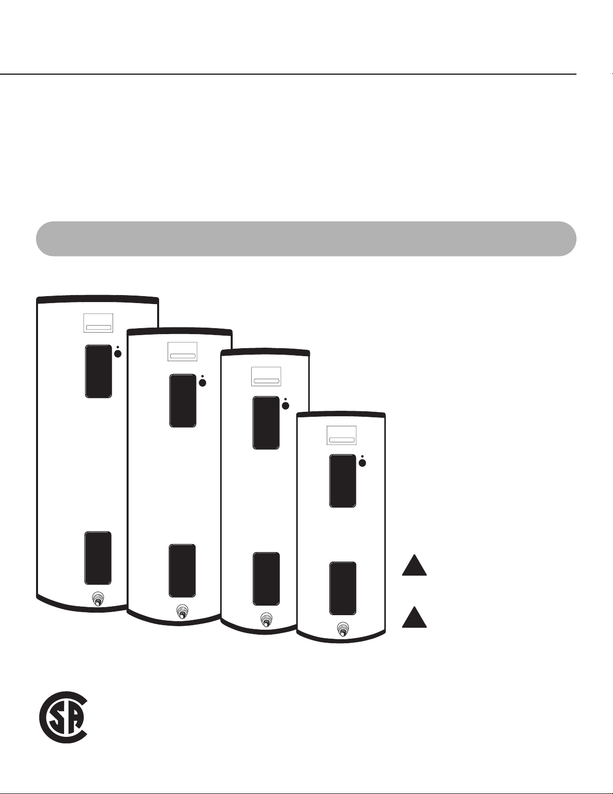
Water Heaters
Electric Residential
The purpose of this manual is twofold: one,
to provide the installer with the basic
directions and recommendations for the
proper installation and adjustment of the
water heater; and two, for the
owner–operator, to explain the features,
operation, safety precautions, maintenance
and troubleshooting of the water heater.
This manual also includes a parts list.
It is imperative that all persons who are
expected to install, operate or adjust this
water heater read the instructions carefully
so they may understand how to perform
these operations. If you do not understand
these instructions or any terms within it,
seek professional advice.
Any questions regarding the operation,
maintenance, service or warranty of this
water heater should be directed to the seller
from whom it was purchased. If additional
information is required, refer to the section
on “If you need service.”
Do not destroy this manual. Please
read carefully and keep in a safe
place for future reference.
Recognize this symbol as an
indication of Important Safety
Information!
Double Element Residential Electric Models
Printed in USA
Use & Care Manual
With Installation Instructions for the Installer
AP11058 Rev. 9 (11/03)
!
!
Page 2
Safety Information
Safety Precautions. . . . . . . 3, 4
Installation Instructions
Location . . . . . . . . . . . . . . . . . 5
W ater Connections . . . . . . . . 6
Electrical Connections . . . . . 8
Operating Instructions
Safety Controls . . . . . . . . . . 12
W ater Temperature . . . . . . . 13
Care and Cleaning
Draining . . . . . . . . . . . . . . . . 14
Extended Shut-Down . . . . . 14
Maintenance. . . . . . . . . . . . . 14
T r oubleshooting T ips
Before Y ou Call
For Service. . . . . . . . . . . . . . 15
Customer Service
Parts List . . . . . . . . . . . . . . . 16
If Y ou Need
Service Assistance . . . . . . . 18
Wiring Diagram . . . . . . . . . 20
2
Inside you will find many helpful hints on how to use and maintain
your water heater properly. Just a little preventive care on your part
can save you a great deal of time and money over the life of your
water heater.
You’ll find many answers to common problems in the Before You
Call For Service section. If you review our chart of Troubleshooting
Tips first, you may not need to call for service at all.
READ THIS MANUAL
FOR YOUR RECORDS
Write the model and serial numbers here:
#
#
You can find them on a label on the appliance.
Staple sales slip orcancelled cheque here.
Proof of the original purchase date is needed to obtain service under
the warranty.
Your safety and the safety of others are very important. There are
many important safety messages in this manual and on your
appliance. Always read and obey all safety messages.
This is the safety alert symbol. Recognize this symbol as
an indication of Important Safety Information!
This symbol alerts you to potential hazards that can kill or
hurt you and others.
All safety messages will follow the safety alert symbol and either
the word “DANGER”, “WARNING”, “CAUTION” or “NOTICE”.
These words mean:
DANGER
An imminently hazardous situation
that will result in death or serious
injury.
WARNING
A potentially hazardous situation that
could result in death or serious injury
and/or damage to property.
CAUTION
A potentially hazardous situation that
may result in minor or moderate
injury.
Notice:
Attention is called to observe a
specified procedure or maintain
a specific condition.
READ THE SAFETY INFORMATION
!
!
!
!
Page 3
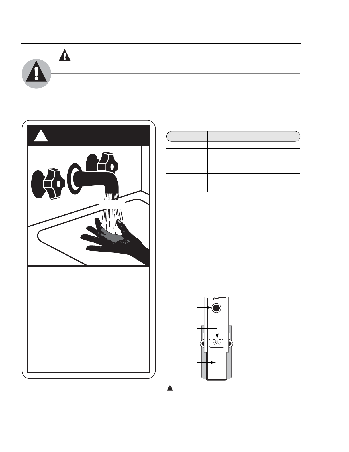
Time/Temperature Relationship in Scalds
Temperature Time To Produce a Serious Burn
49°C (120°F) More than 5 minutes
52°C (125°F) 11/2to 2 minutes
54°C (130°F) About 30 seconds
57 °C (135°F) About 10 seconds
60°C (140°F) Less than 5 seconds
63°C (145°F) Less than 3 seconds
66°C (150°F) About 11/2seconds
68°C (155°F) About 1 second
Table courtesy of Shriners Burn Institute
The chart shown above may be used as a guide
in determining the proper water temperature for your
home.
NOTICE: Households with small children, disabled,
or elderly persons may require a 49°C (120°F) or lower
thermostat setting to prevent contact with “HOT” water.
The temperature of the water in the heater is
regulated by the adjustable surface mounted
thermostat(s) located behind the jacket access
panel(s). Dual element heaters have two thermostats.
The thermostat(s) were set at 60°C (140°F) before
the water heater was shipped from the factory.
The illustration at the left
shows the temperature
adjustment dial used for
setting the water
temperature.
Refer to the Operating
Instructions in this
manual for detailed
instructions in how to
adjust the thermostat(s).
DANGER: Hotter water increases the potential for Hot
Water SCALDS.
IMPOR TANT SAFETY INFORMATION.
READ ALL INSTRUCTIONS BEFORE USING.
3
Reset button
Thermostat
protective cover
(only on certain
models)
Thermostat
dial pointer
WARNING!
WATER TEMPERATURE ADJUSTMENT
Safety and energy conservation are factors to be considered when selecting the water
temperature setting of water heater’s thermostat. Water temperatures above 52°C (125°F) can
cause severe burns or death from scalding. Be sure to read and follow the warnings outlined on
the label pictured below. This label is also located on the water heater near the thermostat
access panel.
NOTICE: Mixing valves are available for reducing point of use
water temperature by mixing hot and cold water in branch
water lines. Contact a licensed plumber or the local plumbing
authority for further information.
!
DANGER
HOT
BURN
Water temperature over 125°F can
cause severe burns instantly or
death from scalds.
Children, disabled and elderly are
at highest risk of being scalded.
See instruction manual before
setting temperature at water
heater.
Feel water before bathing or
showering.
Temperature limiting valves are
available, see manual.
R
T
E
E
S
E
T
R
S
E
170
160
TURN OFF
POWER
BEFORE
SERVICING
110
120
130140150
Page 4

4
IMPOR TANT SAFETY INFORMATION.
READ ALL INSTRUCTIONS BEFORE USING.
WARNING!
For your safety, the information in this manual must be followed to minimize the risk of fire or
explosion, electric shock, or to prevent property damage, personal injury, or loss of life.
Be sure to read and understand the entire Use and Care Manual before attempting to install or
operate this water heater. It may save you time and cost. Pay particular attention to the Safety
Instructions. Failure to follow these warnings could result in serious bodily injury or death.
Should you have problems understanding the instructions in this manual, or have any questions,
STOP, and get help from a qualified service technician, or the local electric utility.
READ AND FOLLOW THIS SAFETY INFORMATION
CAREFULLY.
SAVE THESE INSTRUCTIONS
Have the installer show you the location of the circuit breaker and how to shut it off if
necessary. Turn off the circuit breaker if the water heater has been subjected to overheating,
fire, flood, physical damage or if the ECO fails to shut off.
● Read this manual entirely before installing
or operating the water heater.
● Use this appliance only for its intended
purpose as described in this Use and Care
Manual.
● Be sure your appliance is properly installed
in accordance with local codes and the
provided installation instructions.
● Do not attempt to repair or replace any part
of your water heater unless it is specifically
recommended in this manual. All other
servicing should be referred to a qualified
technician.
SAFETY PRECAUTIONS
Page 5

Installing the water heater.
The location chosen for the water heater must take into consideration the following:
Local Installation Regulations
This water heater must be installed in
accordance with these instructions, local
authorities and codes, utility codes or
utility company requirements, which must
be followed and take precedent over any
recommendation in this manual.
Location
Locate the water heater in a clean dry area
as near as practical to the area of greatest
heated water demand. Long uninsulated hot
water lines can waste energy and water.
Place the water heater in such a manner
that the thermostat and element access
panels can be removed to permit
inspection and servicing such as removal
of elements or checking controls.
The water heater and water lines should be
protected from freezing temperatures. Do
not install the water heater in outdoor,
unprotected areas.
CAUTION: The water heater should not
be located in an area where leakage of the
tank or connections will result in damage to
the area adjacent to it or to lower floors of
the structure. Where such areas cannot be
avoided, it is recommended that a suitable
catch pan, adequately drained, be installed
under the water heater.
A—Diameter of water heater
plus 5 cm (2″) min.
B—Maximum 5 cm (2″)
NOTICE: Auxiliary catch pan MUST conform to local codes.
Catch Pan Kits are available from the store where the waterheater
was purchased, or any water heater distributor.
B
A
To open drain, line should
be at least 1.9 cm (3/4″) ID
and pitched for proper
drainage.
5
Inspect Shipment
Inspect the water heater for possible damage. Check the markings on the rating plate of
the water heater to be certain the power supply corresponds to the water heater
requirements.
Page 6
6
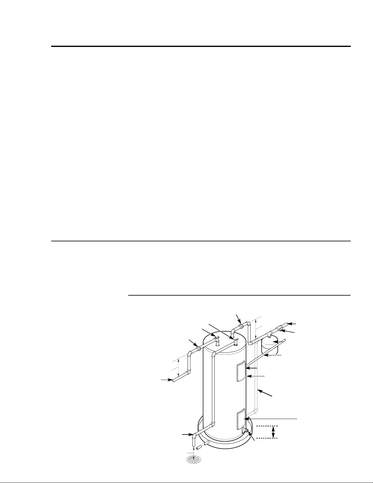
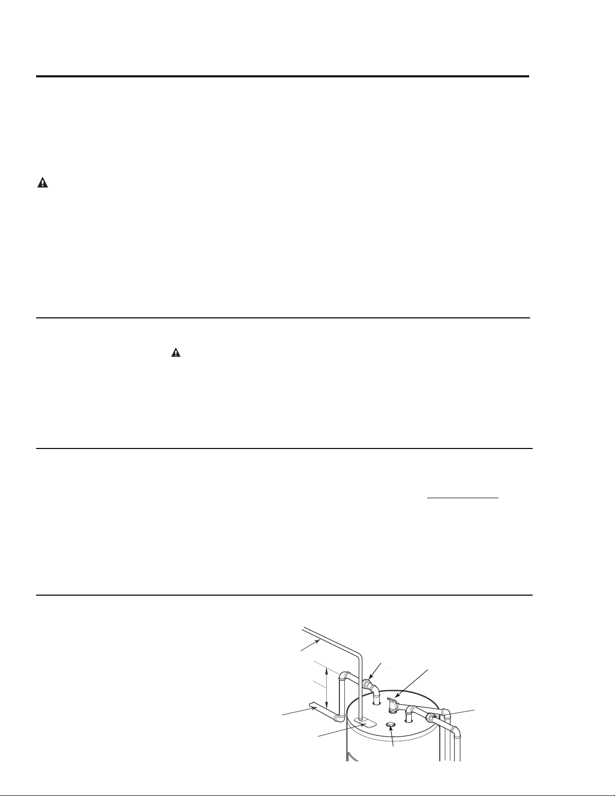
Typical Installation
R
E
L
I
E
F
V
A
L
V
E
H O T
C O L D
To cold water supply*
Jacket access panel
Relief valve discharge line to
suitable open drain
Drain valve
Electrical junction box (inside jacket)
Hot water outlet
to fixtures
Anode
Shut-off valve
Union
Temperature &
pressure relief valve
Thermal expansion tank
(if required)
Heat trap 15 cm (6″)
minimum
15 cm (6″) air gap
Heat trap 15 cm (6″)
minimum
Auxiliary catch pan
5 cm (2’) maximum
To electrical
distribution panel
Jacket access panel
Union
Installing the water heater.
Thermal Expansion
Determine if a check valve exists in the inlet water line. It may have been installed
in the cold water line as a separate back flow preventer, or it may be part of a pressure reducing
valve, water meter or water softener. A check valve located in the cold water inlet line can
cause what is referred to as a “closed water system”. Acold water inlet line with no check
valve or back flow prevention device is referred to as an “open” water system.
As water is heated, it expands in volume and creates an increase in the pressure within
the water system. This action is referred to as “thermal expansion”. In an “open” water
system, expanding water which exceeds the capacity of the water heater flows back into
the city main where the pressure is easily dissipated.
A “closed water system”, however, prevents the expanding water from flowing back into the
main supply line, and the result of “thermal expansion” can create a rapid and dangerous
pressure increase in the water heater and system piping. This rapid pressure increase can
quickly reach the safety setting of the relief valve, causing it to operate during each heating
cycle. Thermal expansion, and the resulting rapid and repeated expansion and contraction of
components in the water heater and piping system can cause premature failure of the relief
valve, and possibly the heater itself. Replacing the relief valve will not correct the problem!
The suggested method of controlling thermal expansion is to install an expansion tank in the
cold water line between the water heater and the check valve (refer to the illustration below).
The expansion tank is designed with an air cushion built in that compresses as the system
pressure increases, thereby relieving the over pressure condition and eliminating the repeated
operation of the relief valve. Other methods of controlling thermal expansion are also available.
Contact your installing contractor, water supplier or plumbing inspector for additional
information regarding this subject.
NOTICE: Do not apply heat to
the HOT or COLD water
connections. If sweat
connections are used, sweat
tubing to adapter before
fitting adapter to the water
connections on heater. Any
heat applied to the water
supply fittings will
permanently damage the dip
tube and or heat traps.
Water Supply Connections
Refer to the illustration below for suggested typical installation. The installation of unions or
flexible copper connectors is recommended on the hot and cold water connections so that the
water heater may be easily disconnected for servicing if necessary. The HOT and COLD
water connections are clearly marked and are 3/4″ NPT on all models. Install a shut-off valve
in the cold water line near the water heater.
To cold water supply*
* Some models are
constructed with a side
cold water inlet and will
not have an opening on
the top of the water
heater.
Page 7
R
E
L
I
E
F
V
A
L
V
E
COLD
HOT
W ARNING: The pressur e
rating of the relief valve must
not exceed 1 034 kPa (150 PSI),
the maximum working
pressure of the water heater as
marked on the rating plate.
A new combination temperature and pressure relief valve, complying with the Standard for Relief Valves and
Automatic Gas Shut-Off Devices for Hot Water Supply Systems, ANSI Z21.22/CSA 4.4 M99, must be
installed in the opening provided and marked for the purpose on the water heater. No valve of any type should
be installed between the relief valve and the tank. Local codes shall govern the installation of relief valves.
Relief Valve
The BTU/h rating of the relief valve must
not be less than the input rating of the
water heater as indicated on the rating
label located on the front of the heater
(1 watt=3.412 BTU/h).
Connect the outlet of the relief valve
to a suitable open drain so that the
discharge water cannot contact live
electrical parts or persons and to eliminate
potential water damage.
Piping used should be of a type approved
for hot water distribution. The discharge
line must be no smaller than the outlet of
the valve and must pitch downward from
the valve to allow complete drainage (by
gravity) of the relief valve and discharge
line. The end of the discharge line should
not be threaded or concealed and should
be protected from freezing. No valve of
any type, restriction or reducer coupling
should be installed in the discharge line.
To Fill the Water Heater
WARNING: The tank must be full of
water before heater is turned on. The water
heater warranty does not cover damage or
failure resulting from operation with an
empty or partially empty tank.
Make certain the drain valve is completely
closed.
Open the shut-off valve in the cold water
supply line.
Open each hot water faucet slowly to
allow the air to vent from the water
heater and piping.
A steady flow of water from the hot water
faucet(s) indicates a full water heater.
7
Condensation
Condensation can form on the tank when
it is first filled with water. Condensation
might also occur with a heavy water draw
and very cold inlet water temperature.
This condition is not unusual, and will
disappear after the water becomes heated.
If, however, the condensation continues,
examine the piping and fittings for
possible leaks.
Additional information on this subject
may be found at www.rheem.com under
“Library”. Scroll down to the Technical
Service Bulletins 1300 Series Section and
choose Bulletin #1303.
Typical Installation (Alternate Construction)
To electrical
distribution panel
Heat trap
15cm (6”) minimum
Hot water outlet
to fixtures
Electrical junction box
(use only copper conductors)
Union
Anode
Temperature
&
Pressure
Relief Valve
Union
Page 8
8
Installing the water heater.
NOTICE: This guide recommends minimum branch circuit sizing and wire size. Referto wiring diagrams in this manual for
field wiring connections.
Branch Circuit Sizing and Wire Size Guide
T otal Water Recommended Over Current Protection CopperWire Size AWGBased
Heater Wattage (fuse or circuit breaker amperage rating) on N.E.C. Table 310-16 (75°C)
208V 240V 277V 480V 208V 240V 277V 480V
3,000 20 20 --- --- 12 12 --- --3,800 25 20 --- --- 10 12 --- --4,000 25 25 --- --- 10 10 --- --4,500 30 25 --- --- 10 10 --- ---
CAUTION: The presence of
water in the piping and water
heater does not provide
sufficient conduction for a
ground. Non-metallic piping,
dielectric unions, flexible
connectors etc. can cause the
water heater to be electrically
isolated.
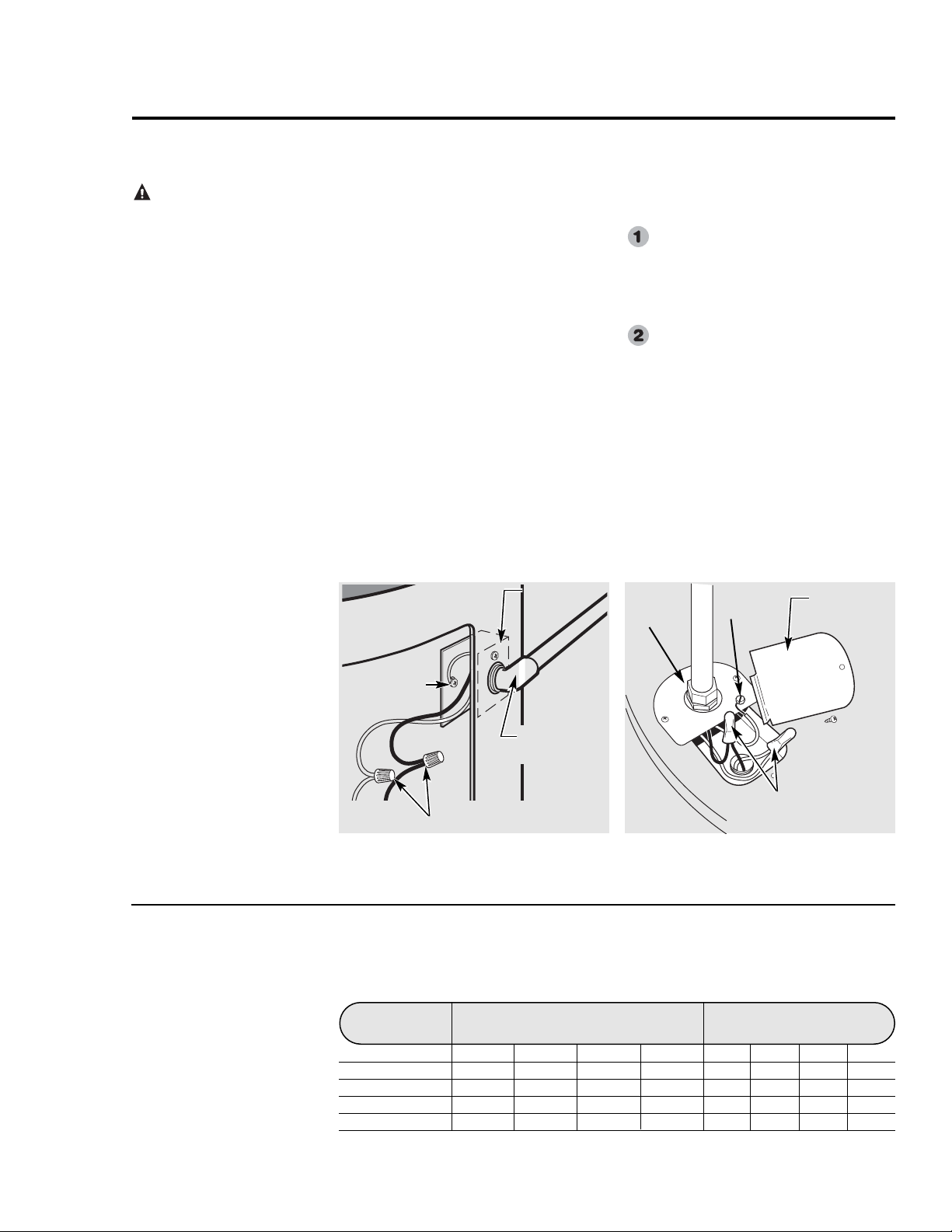
Electrical Connections
A separate branch circuit with copper
conductors, overcurrent protective device
and suitable disconnecting means must be
provided by a qualified electrician.
All wiring must conform to local codes, or
the latest edition of the Canadian
Electrical Code. Refer to wiring diagrams
in the back of this manual for wiring
connections.
The voltage requirements and wattage
load for the water heater are specified
on the rating plate on the front of the
water heater.
The water heater is completely wired
to the junction bracket inside the top
access panel on front of the water heater.
An opening for 1.2 cm (1/2”)
or 1.9 cm (3/4”) electrical fitting is
provided for field wiring connections.
The branch circuit wiring should include
either:
Metallic conduit or metallic sheathed
cable approved for use as a
grounding conductor and installed
with fittings approved for the
purpose.
Non-metallic sheathed cable,
metallic conduit or metallic sheathed
cable not approved for use as a
ground conductor shall include a
separate conductor for grounding. It
should be attached to the ground
terminals of the water heater and the
electrical distribution box.
Water heater junction bracket.
Ground
screw
Wire connections
Junction
bracket
Conduit
connector
Wire connections
Junction
box cover
Conduit
connector
Water heater junction box (Alternate construction)
Ground
screw
WARNING
WARNING
Page 9
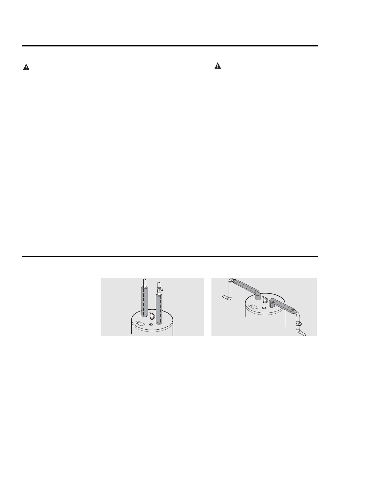
For increased energy efficiency, some
water heaters have been supplied with
two 61cm (24”) sections of pipe
insulation.
Please install the insulation, according to
the illustrations above, that best meets
your requirements.
R
E
L
I
E
F
V
A
L
V
E
COLD
HOT
Typical vertical piping arrangement
R
E
L
I
E
F
V
A
L
V
E
C
OL
D
HO
T
Typical horizontal piping arrangement
Hot and Cold Pipe Insulation Installation
Insulation blankets, available to the
general public, for external use on electric
water heaters are not necessary. The
purpose of an insulation blanket is to
reduce the standby heat loss encountered
with storage tank heaters. This water
heater meets or exceeds CSA standards,
with respect to insulation and standby loss
requirements making an insulation blanket
unnecessary.
The manufacturer’s warranty does not
cover any damage or defect caused by
installation, attachment or use of
any type of energy saving or other
unapproved devices (other than those
authorized by the manufacturer) into, onto
or in conjunction with the water heater.
The use of unauthorized energy saving
devices may shorten the life of the water
heater and may endanger life and property.
The manufacturer disclaims any
responsibility for such loss or injury
resulting from the use of such
unauthorized devices.
CAUTION: If local codes require the
application of an external insulation
blanket to this water heater, pay careful
attention to the following so as not to
restrict the proper function and
operation of the water heater:
● Do not cover the operating or warning
labels attached to the water heater or
attempt to relocate them on the exterior
of insulation blanket.
z Do not apply insulation to the top of the
water heater. this could interfere with
the safe operation of the electrical
junction box.
z Do not cover the jacket access panel(s)
to the thermostat(s) and heating
element(s), or pressure and temperature
relief valve.
z Inspect the insulation blanket frequently.
WARNING: If local
codes require external
application of insulation
blanket kits the
manufacturer’s instructions
included with the kit must
be carefully followed.
Insulation Blankets
9
Page 10
10
Installing the water heater.
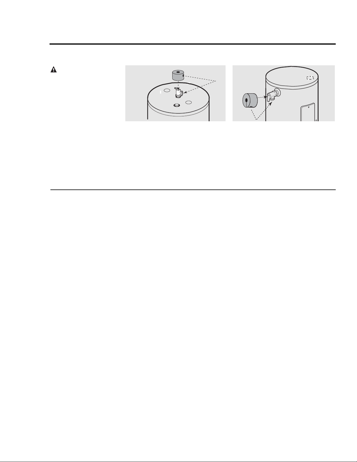
For increased energy efficiency, some
water heaters have been supplied with
a 6cm (2-3/8”) section of pipe insulation.
Please install the insulation, according to
the illustrations above, that best meets
your requirements.
Slip the insulation cover over the T&P
Valve through the center hole and align
the hole in the side with the opening of
the T&P Valve.
R
E
L
I
E
F
V
A
L
V
E
C
OLD
HOT
Typical top connection arrangement
Typical side connection arrangement
Relief Valve Insulation Installation
CAUTION: Ensure the
T&P Valve opening is not
obstructed by the insulation.
Heat Trap
For increased energy efficiency, some
water heaters have been supplied with
factory installed internal or external heat
traps in the hot outlet line and cold water
inlet openings.
NOTICE: Do not apply heat to the HOT or
COLD water connections. If sweat
connections are used, sweat tubing to
adapter before fitting adapter to the water
connections on heater. Any heat applied to
the water supply fittings will permanently
damage the dip tube and/or heat traps.
Page 11

11
Installation Checklist
A. Water Heater Location
B. Water Supply
C. Relief Valve
D. Wiring
❑ Close to area of heated water demand.
❑ Indoors and protected from freezing
temperatures.
❑ Area free of flammable vapours.
❑ Provisions made to protect area from water
damage.
❑ Sufficient room to service heater.
❑ Water heater completely filled with water.
❑ Air purged from water heater and piping.
❑ Water connections tight and free of leaks.
❑ Temperature and Pressure Relief Valve
properly installed and discharge line run to
open drain.
❑ Discharge line protected from freezing.
❑ Power Supply voltage agrees with water
heater rating plate.
❑ Branch circuit wire and fusing or circuit
breaker of proper size.
❑ Electrical connections tight and unit properly
grounded.
Page 12
12
Safety Precautions
Do turn off power to water heater if
it has been subjected to over heating,
fire, flood, physical damage.
Do Not turn on water heater unless it
is filled with water.
Do Not turn on water heater if cold
water supply shut-off valve is closed.
If there is any difficulty in
understanding or following the
Operating Instructions or the Care
and Cleaning section, it is
recommended that a qualified person
or serviceman perform the work.
Operating the water heater.
CAUTION: Hydrogen gas can be produced in a hot water system served by this water heater that has not been used for a
long period of time (generally two weeks or more). HYDROGEN GAS IS EXTREMELY FLAMMABLE!! To dissipate such
gas and to reduce risk of injury, it is recommended that the hot water faucet be opened for several minutes at the kitchen sink
before using any electrical appliance connected to the hot water system. If hydrogen is present, there will be an unusual sound
such as air escaping through the pipe as the water begins to flow. Do not smoke or use an open flame near the faucet at the
time it is open.
Safety Controls
The water heater is equipped with a
combination thermostat and temperature
limiting control (ECO) that is located
above the heating element in contact with
the tank surface. If for any reason the water
temperature becomes excessively high, the
temperature limiting control (ECO) breaks
the power circuit to the heating element.
Once the control opens, it must be reset
manually.
CAUTION: The cause of the high
temperature condition must be investigated
by qualified service technician and
corrective action must be taken before
placing the water heater in service again.
To reset the temperature limiting control:
Turn off the power to the water
heater.
Remove the jacket access panel(s)
and insulation.
The thermostat protective cover
should not be removed. (Only on
certain models).
Press the red RESET button.
Replace the insulation and jacket
access panel(s) before turning on the
power to the water heater.
WARNING: If the water
heater has been subjected to
flood, fire, or physical damage,
turn off power and water to
the water heater.
Do not operate the water
heater again until it has been
thoroughly checked by
qualified service personnel.
Page 13

If adjustment is necessary…
Turn off the power to the water
heater.
Remove the jacket access panel(s)
and insulation exposing the
thermostat(s).
The thermostat protective cover(s)
should not be removed (Only on
certain models).
Using a small screwdriver, set the
thermostat(s) dial pointer(s) to
the desired temperature.
Replace the insulation and jacket
access panel(s). Turn on the power to
the water heater.
Thermostat and protective cover.
Time/Temperature Relationship in Scalds
Temperature Time To Produce a Serious Burn
49°C (120°F) More than 5 minutes
52°C (125°F) 11/2to 2 minutes
54°C (130°F) About 30 seconds
57°C (135°F) About 10 seconds
60°C (140°F) Less than 5 seconds
63°C (145°F) Less than 3 seconds
66°C (150°F) About 11/2seconds
68°C (155°F) About 1 second
Table courtesy of Shriners Burn Institute
DANGER: There is a hot
water scald potential
if the thermostat is set
too high. Households with small
children, disabled, or elderly
persons may require a 49°C
(120°F) or lower thermostat
setting to prevent contact with
HOT water.
WaterTemperature Setting
The temperature of the water in the water
heater can be regulated by setting the
temperature dial of the adjustable surface
mounted thermostat(s) located behind the
jacket access panel(s).
Dual element heaters have two
thermostats.
Safety and energy conservation are factors
to be considered when selecting the water
temperature setting of the water heater’s
thermostat(s). The lower the temperature
setting, the greater the savings in energy
and operating costs.
The thermostat(s) are factory set at 60°C
(140°F) or less where local codes require.
This is the recommended starting point.
Water temperatures above 52°C (125°F)
can cause severe burns or death from
scalding. Be sure to read and follow the
warnings outlined in this manual and on
the label on the water heater. This label is
located on the water heater near the
thermostat access panel.
Mixing valves for reducing point of use
water temperature by mixing hot and cold
water in branch water lines are available.
Contact a licensed plumber or the local
plumbing authority for further
information.
The chart below may be used as a guide in
determining the proper water temperature
for your home.
Reset button
Thermostat
protective
cover (only on
certain
models)
Thermostat
dial pointer
13
R
T
E
E
S
S
E
E
T
170
160
TURN OFF
POWER
BEFORE
SERVICING
R
110
120
130140150
Page 14

14
Routine Preventative Maintenance
Properly maintained, your water heater
will provide years of dependable troublefree service.
It is suggested that a routine preventive
maintenance program be established and
followed by the user.
It is further recommended that a periodic
inspection of the operating controls,
heating element and wiring should be
made by service personnel qualified in
electric appliance repair.
Most electrical appliances, even when
new, make some sound when in operation.
If the hissing or singing sound level
increases excessively, the electric heating
element may require cleaning. Contact a
qualified installer or plumbing contract to
inspect.
At least once a year, lift and release the
lever handle on the temperature pressure
relief valve, located near the top of the
water heater, to make certain the valve
operates freely. Allow several litres to
flush through the discharge line to an open
drain.
A water heater’s tank can act as a settling
basin for solids suspended in the water. It
is therefore not uncommon for hard water
deposits to accumulate in the bottom of the
tank. It is suggested that a few litres of
water be drained from the water heater’s
tank every month to clean the tank of
these deposits.
Rapid closing of faucets or solenoid
valves in automatic water using appliances
can cause a banging noise heard in a water
pipe. Strategically located risers in the
water pipe system or water hammer
arresting devices can be used to minimize
the problem.
The anode rod should be removed from the
water heater’s tank annually for inspection
and replaced when more than 15 cm (6”) of
core wire is exposed at either end of the rod.
Make sure the cold water supply is turned
off before removing anode rod.
NOTICE: Do not remove the anode rod
from the water heater’s tank, except for
inspection and/or replacement, as operation
with the anode rod removed will greatly
shorten the life of the glass lined tank and
will exclude warranty coverage.
Care and cleaning of the water heater.
Draining the Water Heater
CAUTION: Shut off power to the water
heater before draining water.
DANGER: Before manually operating
the relief valve, make certain no one will be
exposed to the hot water released by the
valve. The water drained from the tank may
be hot enough to present a scald hazard and
should be directed to a suitable drain to
prevent injury or damage.
In order to drain the water heater, turn off
the cold water supply. Open a hot water
faucet or lift the handle on the relief valve
to admit air to the tank.
Attach a garden hose to the drain valve on
the water heater and direct the stream of
water to a drain. Open the valve.
Vacation and Extended Shut-Down
If the water heater is to remain idle for an
extended period of time, the power and
water to the appliance should be turned off
to conserve energy and prevent a build-up
of dangerous hydrogen gas.
The water heater and piping should be
drained if they might be subjected to
freezing temperatures.
After a long shut-down period, the water
heater’s operation and controls should be
checked by qualified service personnel.
Make certain the water heater is
completely filled again before placing it in
operation.
NOTICE: Refer to the
Hydrogen Gas Caution in the
Operating Instructions.
DANGER: Before
manually operating the relief
valve, make certain no one will
be exposed to the danger of
coming in contact with the hot
water released by the valve.
The water may be hot enough
to create a scald hazard. The
water should be released into a
suitable drain to prevent
injury or property damage.
NOTICE: If the temperature
and pressure relief valve
on the hot water heater
discharges periodically,
this may be due to thermal
expansion in a closed
water system. Contact
the water supplier or
your plumbing contractor on
how to correct this.
Do not plug the relief
valve outlet.
Page 15

15
Before You Call For Service…
Troubleshooting Tips
Save time and money! Review the chart on this page first
and you may not need to call for service.
Problem Possible Causes What To Do
Rumbling noise Water conditions in your ● Remove and clean the heating elements.
home caused a build up of
scale or mineral deposits
on the heating elements.
Relief valve Pressure build up caused ● This is an unacceptable condition and must be
producing popping by thermal expansion corrected. Contact the water supplier or plumbing
noise or draining in a closed system. contractor on how to correct this. Do not plug the
relief valve outlet.
Rattling noise Internal heat trap ● This is normal for heat trap fittings when in operation
during periods fittings in operation. and does not indicate a need for service.
of water usage
Not enough or Water usage may have ● Wait for the water heater to recover after an abnormal
no hot water exceeded the capacity demand.
of the water heater.
A fuse is blown or a circuit ● Replace fuse or reset circuit breaker.
breaker tripped.
Electric supply may be off. ● Make sure electric supply to water heater and
disconnect switch, if used, are in the ON position.
The thermostat may ● See the Temperature regulation of the water heater
be set too low. section of this manual.
Leaking or open hot ● Make sure all faucets are closed.
water faucets.
Electric service to your ● Contact the local electric utility.
home may be interrupted.
Improper wiring. ● See the Installing the water heater section of this
manual.
Manual reset limit (ECO). ● See the Temperature regulation of the water heater
section of this manual.
Cold water inlet ● This is normal. The colder inlet water takes longer
temperature may be to heat.
colder during the
winter months.
Water is too hot The thermostat ● See the Temperature regulation of the water heater
is set too high. section of this manual.
CAUTION: For your safety DO NOT attempt repairof electrical wiring, thermostats,
heating elements or other safety devices. Refer repairs to qualified service personnel.
Page 16

16
Replacement Parts.
Instructions For Placing a Parts Order
Address parts orders to the distributor or
store where the heater was purchased.
All parts orders should include:
The model and serial number of the
water heater from the rating plate.
Specify voltage and wattage as
marked on the rating plate.
Part description (as noted below) and
number of parts desired.
CAUTION: For your safety DO NOT
attempt repair of electrical wiring,
thermostat(s), heating elements or other
operating controls. Refer repairs to qualified
service personnel.
NOTICE: Some parts may vary in appearance
from model to model.
NOTICE: Models
constructed with a
side cold water inlet
will not contain a
Dip Tube or a Dip
Tube Gasket.
Internal heat trap
Internal heat trap
gasket
Anode rod
Alternate Construction
Temperature & Pressure
relief valve
Dip tube
Dip tube gasket
Heating element
(for certain models)
Dip tube/internal heat trap
Dip tube gasket
Anode rod
Temperature & Pressure
relief valve
(Supplied with certain models)
Electrical
junction box
Upper thermostat
Upper thermostat protective cover
T
E
S
E
R
R
E
S
E
T
0
9
0
4
1
0
0
1
0
3
C
1
0
S
1
1
I
0
D
2
1
O -
-
M
R
E
H
T
FF
O
N
R
U
ER
T
W
O
P
RE
O
F
E
NG
I
B
IC
V
R
E
S
Junction box cover
Plate cover
Some models may have
been supplied with
External heat traps
in lieu of Internal heat traps
(On certain models)
Heating element
gasket
Heating element
Drain valve shroud
Drain valve
Thermostat
bracket
Lower
Thermostat
0
9
0
4
1
0
0
1
0
3
C
1
0
1
S
1
I
0
D
2
1
-
O
M
R
E
H
T
Cavity
insulation
Jacket
access
panels
F
F
O
N
R
U
ER
T
W
E
PO
OR
G
EF
IN
B
C
I
V
R
E
S
Lower thermostat protective cover
Thermostat bracket
(on certain models)
Alternate
construction
jacket access
panel
Page 17

17
Cavity Insert Instructions (for certain models)
The following instructions are intended for
qualified service personnel ONLY, and should only
be done when necessary.
In order to replace the thermostat or heating element,
remove the cavity insert crossbar by following the
instructions below:
Turn off the power to the water heater.
Remove the jacket access panel(s) and insulation.
Rotate the crossbar up and down until it breaks away
from the remainder of the cavity insert.
(See illustration to the left)
Discard the crossbar. It cannot and need not be
replaced.
Replace the thermostat and/or element as necessary.
Replace the insulation and jacket access panel(s)
before turning on the power to the water heater.
NOTICE: The cavity insert crossbar is necessary for the
manufacturing process only. The removal of the
crossbar will not interfere with the operation of the
water heater.
Page 18

18
IF YOU NEED SERVICE
1. Should you have any questions about your new water heater, or if it requires
adjustment, repair, or routine maintenance, it is suggested that you first contact
your installer, plumbing contractor or previously agreed upon service agency. In
the event the firm has moved, or is unavailable, refer to the telephone directory,
commercial listings or local utility for qualified service assistance.
2. Should your problem not be solved to your complete satisfaction, you should
then contact the Manufacturer’s National Service Department at the following
address:
Rheem Canada Ltd./Ltée.
128 Barton Street West
P.O. Box 2846, Station A
Hamilton, Ontario Canada L8N 3P3
Customer Service: 1-800-432-8373
Warranty: 1-800-263-8342
When contacting the manufacturer, the following information will be requested:
a. Model and serial number of the water heater as shown on the rating plate attached
to the jacket of the heater.
b. Address where the water heater is located and physical location.
c. Name and address of installer and any service agency who performed service on
the water heater.
d. Date of original installation and dates any service work was performed.
e. Details of the problems as you can best describe them.
f. List of people, with dates, who have been contacted regarding your problem.
Page 19

19
Notes
Page 20

20
Wiring diagram
Wiring Diagram for Type–59T Therm-o-disc Thermostats
Double Element Models
BRANCH CIRCUIT
TO ELECTRICAL
DISTRIBUTION PANEL
G*
L1
240 V.
L2
YELLOW
BLACK
LOWER
HEATING
ELEMENT
BLACK
1 3
2
1
2
1
2
RED
4
4
BLUE
BLACK
BOX
JUNCTION
UPPER THERMOSTAT
& HIGH TEMP LIMIT
(ECO)
UPPER
HEATING
ELEMENT
RED
LOWER
THERMOSTAT
Page 21

20
NOIR
Schémas de câblage.
Schémas de câblage des thermostats Therm-o-disc
Modèles à élément double
INFÉRIEUR
CHAUFFANT
ÉLÉMENT
INFÉRIEUR
THERMOSTAT
NOIR
ROUGE
SUPÉRIEUR
CHAUFFANT
ÉLÉMENT
BLEU
DE TEMP. SUP.
ET LIMITEUR
THERMOSTAT
JONCTION
BOÎTE DE
DISTRIBUTION ÉLECTRIQUE
VERS LE PANNEAU DE
CIRCUIT DE DÉRIVATION
4
4
ROUGE
L2
2
1
JAUNE
2
1
2
1 3
NOIR
L1
G*
Page 22

19
Notes
Page 23

18
Pour obtenir l'assistance du service à la clientèle
1. Si vous avez une question quelconque au sujet de votre chauffe-eau neuf ou s'il
nécessite ajustement, réparation ou entretien routinier, il est suggéré de
communiquer d'abord avec votre installateur, entrepreneur de plomberie ou agence
de service précédemment acceptée. Dans le cas où la compagnie a déménagé ou
n'est pas disponible, consulter les listes commerciales de l'annuaire téléphonique
pour obtenir une assistance de service qualifiée.
2. Si votre problème n'est pas résolu à votre satisfaction complète, veuillez
communiquer avec le département de service du fabricant à l'adresse suivante:
Rheem Canada Ltd./Ltée.
128 Barton Street West
P.O. Box 2846, Station A
Hamilton, Ontario Canada L8N 3P3
Téléphone: Service à la clientèle 1-800-432-8373
Garntie: 1-800-263-8342
Lors de tout contact avec le fabricant, les renseignements suivants doivent être
disponibles:
a. Numéros de modèle et de série du chauffe-eau tels qu'indiqués sur la plaque
signalétique collée sur l'enveloppe du chauffe-eau..
b. L'adresse où le chauffe-eau est situé et peut être examiné.
c. Nom et adresse de l'installateur ou de l'agence de service ayant effectué l'entretien
du chauffe-eau.
d. Date de l'installation originale et dates de tous services d'entretien effectués.
e. Détails du problème au mieux de votre connaissance.
f. Liste des personnes, avec les dates, qui ont été contactées au sujet de votre
problème.
Page 24

17
Directives pour barre tranversale de la cavité
Les directives suivantes sont réservées
UNIQUEMENT à l'intention de personnel de
service qualifié et ne doivent être effectuées que
suivant nécessité.
De manière à remplacer le thermostat ou l'élément de
chauffage, enlever la barre transversale de la cavité en
suivant les directives ci-dessous :
Couper l'alimentation électrique au chauffe-eau.
Enlever le panneau d'accès de l'enveloppe et
l'isolation.
Faire pivoter la barre transversale jusqu'à ce qu'elle
casse et se sépare de la cavité. (Voir l'illustration à
gauche).
Jeter la barre transversale, elle ne peut pas être
remplacée.
Remplacer le thermostat et/ou l'élément de chauffage,
selon le besoin.
Replacer l'isolation et le panneau d'accès de
l'enveloppe avant de remettre le chauffe-eau sous
tension.
AVIS : La barre transversale de la cavité n'est
nécessaire que pour le processus de fabrication. Le fait
d'enlever la barre transversale n'affectera pas le
fonctionnement du chauffe-eau.
Page 25

16
de l'enveloppe
Pièces de rechange.
Pour commander des pièces
Adresser les commandes de pièces au
distributeur ou au magasin où le chauffe-
eau a été acheté.
Toutes les commandes de pièces doivent
comprendre:
Les numéros de modèle et de série
du chauffe-eau, qui figurent sur la
plaque signalétique.
La tension et la puissance indiquées
sur la plaque signalétique.
La description (comme indiqué ci-
dessous) et le numéro des pièces
désirées.
ATTENTION : Pourvotre sécurité, ne
tentez PAS de réparer le câblage électrique,
les thermostats, les éléments chauffants ou
autres dispositifs de sécurité. Confiez ces
réparations à un technicien qualifié.
REMARQUE : L’apparence de certaines pièces
peut varier d’un modèle à l’autre.
d'accès
panneau
alternative
Construction
de l'enveloppe
d'accès
Panneau
thermostat
Support du
Capot protecteur du thermostat inférieur
SE
R
V
IC
B
I
N
EF
G
O
R
P
E
O
W
T
E
U
R
R
N
O
F
F
T
H
E
R
M
O
-
1
2
D
0
I
1
S
1
0
1
C
3
0
1
0
0
1
4
0
9
0
d'accès
du panneau
Insolant
S
E
R
V
ICI
B
N
E
G
F
O
RE
P
O
W
T
E
UR
R
N
O
FF
inférieur
Thermostat
thermostat
Support du
T
H
E
R
M
- O -
1
2
D
0
I
1
1
S
0
C
1
3
0
1
0
0
1
4
0
9
0
T
E
S
E
R
R
E
S
E
T
Robinet de purge
Élément chauffant
chauffant
Joint de l'élément
Épaulement du robinet de purge
Capot protecteur du thermostat supérieur
Thermostat supérieur
junction
Boîte de
Soupape de sécurité
(fourni sur certains modèles seul)
chaleur-entrée d'eau chaude
Raccord pour pièce à
de plat
Couverture
de jonction
Couverture de boîte
Anode
Joint du tube immergé
Tube immergé
Élément chauffant
modèles seul)
certains
(fourni sur
d'eau chaude
chaleur-sortie
pièce à
Raccord pour
Anode
Joint du tube immergé
Tube immergé
(pour certains modèles)
Soupape de sécurité
Construction Alternative
Page 26

Avant d’appeler un réparateur...
Conseils de dépannage
Économisez du temps et de l’argent! Consultez
d’abord le tableau ci-dessous. Vous pourriez vous
éviter d’appeler un réparateur.
Problème Causes possibles Correctifs
Grondement La qualité de l’eau de votre ● Enlevez et nettoyez les éléments chauffants.
résidence a provoqué une
accumulation de tartre ou
de dépôts minéraux sur les
éléments chauffants.
La soupape de Accumulation de pression ● Ce phénomène est inacceptable et doit être corrigé.
sécurité fait causée par une expansion Communiquez avec votre fournisseur d’eau ou un
entendre un thermique dans un système entrepreneur en plomberie pour savoir comment
crépitement fermé. corriger ce problème. Ne bouchez pas l’orifice de
ou coule sortie de la soupape de sécurité.
Bruit de cliquetis Fonctionnement des raccords ● Ce phénomène est normal lorsque les raccords du
lors de la du piège à chaleur interne. piège à chaleur fonctionne. Ce bruit n’indique
consommation nullement que le chauffe-eau a besoin de réparation.
d’eau chaude
Peu ou pas La consommation d’eau peut ● Laissez le temps au chauffe-eau de chauffer l’eau
d’eau chaude avoir dépassé la capacité après une demande anormalement élevée.
du chauffe-eau.
Un fusible est grillé ou un ● Remplacez le fusible ou réenclenchez le disjoncteur.
disjoncteur est déclenché.
L’alimentation électrique est ● Assurez-vous que le chauffe-eau est sous tension et
peut-être coupée. que l’interrupteur principal, le cas échéant, est réglé
à ON (Marche).
Le thermostat est peut-être ● Voir la section «Réglage de la température du chauffe-
réglé à une température trop eau» dans le présent manuel.
basse.
Les robinets d’eau chaude ● Assurez-vous que tous les robinets sont fermés.
fuient ou sont ouverts.
Panne de courant possible. ● Communiquez avec votre fournisseur local d’électricité.
Câblage incorrect. ● Reportez-vous à la section «Installation du chauffe-
eau» du présent manuel.
Ouverture du limiteur de ● Reportez-vous à la section «Réglage de la
température manuel. température du chauffe-eau» du présent manuel.
La température de l’eau ● Ce phénomène est normal. L’eau plus froide prend
froide peut être plus basse plus de temps à chauffer.
pendant les mois d’hiver.
Eau trop chaude Le thermostat est réglé à ● Reportez-vous à la section «Réglage de la température
une température trop élevée. du chauffe-eau» dans le présent manuel.
ATTENTION : Pourvotre sécurité, ne tentez PAS de réparerle câblage électrique, les thermostats, les éléments
chauffants ou autres dispositifs de sécurité. Confiez ces réparations à un technicien qualifié.
15
Page 27

Entretien préventif courant
Si vous l’entretenez de la façon appropriée,
votre chauffe-eau vous offrira un rendement
fiable et sans problèmes pendant des années.
Nous suggérons à l’utilisateur d’élaborer
et de suivre un programme d’entretien
préventif courant.
Nous recommandons également de faire
inspecter périodiquement le fonctionnement
des commandes, les éléments chauffants et le
câblage par un réparateur qualifié spécialisé
dans l’entretien des appareils électriques.
La plupart des appareils électriques, même
neufs, font entendre certains bruits pendant
leur fonctionnement. Si le bruit de sifflement
ou de résonance augmente considérablement,
il est possible que l’élément chauffant
électrique ait besoin d’un nettoyage.
Faites-le vérifier par un installateur
qualifié ou un entrepreneur en plomberie.
Au moins une fois par année, relevez et
relâchez la manette de la soupape de
sécurité à température, qui se trouve près
du dessus du chauffe-eau, pour vous assurer
qu’elle fonctionne correctement. Laissez
couler dans un renvoi ouvert plusieurs
litres d’eau par la conduite de décharge.
Le réservoir d’un chauffe-eau peut
constituer en quelque sorte un bassin de
décantation pour les matières solides en
suspension dans l’eau.
Par conséquent, il n’est pas rare que des
dépôts de minéraux s'accumulent dans le
fond du réservoir. Nous suggérons de
vidanger chaque mois quelques litres
d’eau du chauffe-eau pour éliminer ces
dépôts.
La fermeture rapide des robinets ou des
électrovannes dans les appareils qui sont
automatiquement alimentés en eau peut
provoquer un bruit de cognement dans les
canalisations d’eau. Pour réduire au
minimum ce problème, on peut installer à
des endroits stratégiques une colonne
montante dans le système de distribution
d’eau ou des dispositifs antibéliers.
Dans le but de l’inspecter, il faut enlever
chaque année l’anode du chauffe-eau et la
remplacer lorsqu’une longueur de plus de
15 cm (6 po) de fil est exposée à l’une ou
l’autre de ses extrémités.
Avant d’enlever l’ancienne anode, assurez-
vous de fermer le robinet d’alimentation
en eau froide.
AVIS : N’enlevez pas l’anode du réservoir du
chauffe-eau, sauf pour l’inspecteret(ou) la
remplacer, car le fonctionnement sans l’anode
réduit considérablement la vie du
revêtement de verre du réservoir et exclura
la protection de la garantie.
Entretien et nettoyage du chauffe-eau.
Vidange du chauffe-eau
ATTENTION : Avant de vidanger l’eau,
coupez l’alimentation électrique du chauffe-
eau.
DANGER : Avant d’actionner
manuellement la soupape de sécurité,
assurez-vous que personne ne sera
éclaboussé par l’eau chaude expulsée par la
soupape. L’eau provenant du chauffe-eau
peut être suffisamment chaude pour causer
des brûlures. Pour éviter toute blessure ou
dommage, dirigez l’eau dans un renvoi
adéquat.
Pour vidanger le chauffe-eau, fermez le
robinet d’arrêt de la conduite
d’alimentation en eau froide. Ouvrez un
robinet d’eau chaude ou relevez la
manette de la soupape de sécurité pour
faire entrer de l’air dans le réservoir.
Fixez un tuyau d’arrosage au robinet de
purge du chauffe-eau et dirigez l’eau dans
un renvoi. Ouvrez le robinet.
DANGER : Avant
d’actionner manuellement la
soupape de sécurité, assurez-
vous que personne ne sera
éclaboussé par l’eau chaude
expulsée par la soupape. L’eau
provenant du chauffe-eau peut
être suffisamment chaude
pour causer des brûlures. Pour
éviter toute blessure ou
dommage, dirigez l’eau dans
un renvoi adéquat.
AVIS : Si la soupape de
sécurité à pression et
température du chauffe-eau
effectue régulièrement des
purges, cette situation peut
être attribuable à une
expansion thermique dans le
système de distribution d’eau
fermé. Pour corriger ce
problème, communiquez avec
votre fournisseur d’eau ou
votre entrepreneur en
plomberie. Ne bloquez pas
l’orifice de sortie de la
soupape de sécurité.
Vacances et arrêt prolongé
Si le chauffe-eau n’est pas utilisé pendant
une période prolongée, il faut couper
l’alimentation électrique et en eau du
chauffe-eau pour conserver l’énergie et éviter
une accumulation dangereuse d'hydrogène.
Il faut vidanger le chauffe-eau et les
canalisations s’ils sont exposés à une
température inférieure au point de
congélation.
Après une longue période d'arrêt, il faut
faire vérifier les commandes et le
fonctionnement du chauffe-eau par un
technicien qualifié. Avant de le remettre
en marche, assurez-vous que le chauffe-
eau est entièrement rempli d’eau.
AVIS: Reportez-vous à la mise
en garde concernant
l’hydrogène dans les Directives
de fonctionnement.
14
Page 28

13
Fonctionnement du chauffe-eau.
S’il faut modifier le réglage...
Coupez l’alimentation électrique au
chauffe-eau.
Enlevez le ou les panneaux d’accès
de l’enveloppe, ainsi que l’isolant,
pour accéder au(x) thermostat(s).
Il ne faut pas enlever le capot
protecteur du ou des thermostats.
À l’aide d’un petit tournevis, réglez
les aiguilles doubles du ou des
thermostats à la température désirée.
Remettez en place l’isolant,
ainsi que le ou les panneaux
d’accès de l’enveloppe. Rétablissez
l’alimentation électrique du chauffe-
eau.
Thermostat et capot protecteur.
DANGER : Un réglage
trop élevé du thermostat
présente des dangers de
brûlures par l’eau chaude.
Dans les foyers où il y
a de jeunes enfants,
des handicapés ou des
personnes âgées, il peut être
nécessaire de régler
le thermostat à 49 °C (120 °F) ou
moins pour éviter tout contact
avec une eau BRÛLANTE.
Réglage de la température de l’eau
La température de l’eau du chauffe-eau peut
être réglée en modifiant le réglage du cadran
de température du ou des thermostats
réglables en applique situés derrière le ou
les panneaux d’accès de l’enveloppe.
Les chauffe-eau possédant deux éléments
chauffants sont dotés de deux thermostats.
La sécurité et la consommation d’énergie
constituent des facteurs dont il faut tenir
compte lors du réglage de la température
de l’eau sur le thermostat du chauffe-eau.
Plus la température est basse, plus les
économies en énergie et en frais
d'utilisation sont grandes.
Le ou les thermostats ont été réglés à
l’usine à 60 °C (140 °F) ou moins lorsque
les codes locaux l’exigent. Ce réglage
constitue le point de départ recommandé.
Une eau dont la température est supérieure
à 52 °C (125 °F) peut causer des blessures
graves ou mortelles. Veuillez lire et suivre
les mises en garde indiquées dans le
présent manuel et sur l’étiquette apposée
sur le chauffe-eau. Cette étiquette est
située près du panneau d'accès du
thermostat.
Il existe également des robinets mélangeurs
qui abaissent la température de l’eau au
point d’utilisation en mélangeant l’eau
chaude et l’eau froide dans les conduites
d’eau. Pour de plus amples renseignements
à ce sujet, communiquez avec un plombier
agréé ou les autorités compétentes en
plomberie de votre région.
Vous pouvez vous servir du tableau ci-
dessous comme guide pour choisir la
température d’eau appropriée pour votre
résidence.
Bouton de
remise en
marche
Capot
protecteur du
thermostat
Aiguille double
du thermostat
Relation temps-température lors de brûlures
Température T emps pour causer une brûlure grave
49 °C (120 °F) Plus de 5 minutes
52 °C (125 °F) 1 1/
2 à 2 minutes
54 °C (130 °F) 30 secondes environ
57 °C (135 °F) 10 secondes environ
60 °C (140 °F) Moins de 5 secondes
63 °C (145 °F) Moins de 3 secondes
66 °C (150 °F) 1 1/2 seconde environ
68 °C (155 °F) 1 seconde environ
Source : Shriners Burn Institute
SERVICING
BEFORE
POWER
TURN OFF
130140150
160
120
170
110
R
T
E
E
S
S
E
E
T
R
Page 29

12
Mesures de sécurité
Coupez l’alimentation électrique au
chauffe-eau si ce dernier surchauffe
ou présente des dommages, ou s’il y
a eu incendie ou inondation.
Ne mettez pas en marche le chauffe-
eau tant qu’il n’est pas rempli d’eau.
Ne mettez pas en marche le chauffe-
eau si le robinet d’arrêt de la conduite
d’alimentation en eau froide est fermé.
Si vous éprouvez de la difficulté à
comprendre ou à suivre les directives
de fonctionnement ou la section
«Entretien et nettoyage», nous vous
recommandons de confier les travaux
à une personne ou un réparateur
qualifiés.
Fonctionnement du chauffe-eau.
ATTENTION : De l’hydrogène peut se former dans un système de chauffage à eau chaude, alimenté par ce chauffe-eau, qui
n’a pas été utilisé pendant une période prolongée (généralement deux semaines ou plus). L’HYDROGÈNE EST UN GAZ
EXTRÊMEMENT INFLAMMABLE! Pour dissiper ce gaz et réduire les risques de blessures, nous vous recommandons
d’ouvrir le robinet d’eau chaude de l’évier de la cuisine pendant plusieurs minutes avant d’utiliser un appareil électrique
raccordé au système d’alimentation en eau chaude. Lorsqu’il y a de l’hydrogène dans le système, vous entendrez un bruit
inhabituel, comme de l’air qui s’échappe du robinet lorsque l’eau commence à couler. Lorsque vous ouvrez le robinet, ne fumez
pas ou n’utilisez pas une flamme nue.
MISE EN GARDE : Si le
chauffe-eau présente des
dommages ou a été exposé à
un inondation ou un incendie,
coupez l’alimenation
électrique et en eau du
chauffe-eau.
Ne faites pas fonctionner le
chauffe-eau avant de l’avoir fait
entièrement vérifier par un
technicien qualifié.
Dispositifs de sécurité
Le chauffe-eau est muni d’un thermostat
et d’un limiteur de température situés au-
dessus de l’élément chauffant, en contact
avec la surface du réservoir. Si pour
quelque raison que ce soit la température
de l’eau devient trop élevée, le limiteur de
température coupe l’alimentation
électrique à l’élément chauffant. Lorsque
ce limiteur ouvre, il faut le réenclencher
de façon manuelle.
ATTENTION : Il faut faire vérifier par
un technicien qualifié la cause d’une
température élevée et prendre des mesures
correctives appropriées avant de remettre le
chauffe-eau en service.
Pour réenclencher le limiteur de
température :
Coupez l’alimentation électrique au
chauffe-eau.
Enlevez le ou les panneaux d’accès
de l’enveloppe, ainsi que l’isolant.
Il ne faut pas enlever le capot
protecteur du thermostat.
Appuyez sur le bouton rouge de
REMISE EN MARCHE.
Remettez en place l’isolant et le ou
les panneaux d’accès de l’enveloppe,
puis rétablissez l’alimentation
électrique du chauffe-eau.
Système indicateur de l’élément SmartWater™
Si votre chauffe-eau est doté de ce
système, chaque élément chauffant
possède un voyant indicateur visible au
travers du manchon qui s’allumera lorsque
l’élément fonctionne. Un seul indicateur à
la fois s’allumera en tout temps. En
général, ce sera l’élément inférieur.
L’indicateur supérieur ne s’allume qu’au
cours de la mise en route initiale ou si la
demande en eau chaude est considérable.
Voyez la section sur les conseils de
dépannage à la page 12 pour les
informations supplémentaires sur le
fonctionnement du système indicateur des
éléments SmartWater™.
Page 30

Liste des vérifications d’installation
11
Emplacement du chauffe-eau
■ Proche de l'endroit de la demande
d'eau chaude.
■ À l'intérieur et protégé des
températures inférieures au gel.
■ Endroit exempt de vapeurs
inflammables.
■ Dispositions prises pour protéger
l'endroit de dégâts par l'eau.
■ Suffisamment de place pour
l'entretien du chauffe-eau.
Alimentation en eau
■ Chauffe-eau complètement rempli
d'eau.
■ Chauffe-eau et canalisation purgés
d'air.
■ Connexions d'eau bien serrées et
exemptes de fuites.
Soupape de sûreté
■ Soupape de sûreté de température
et de pression adéquatement
installée et canalisation
d'évacuation vers un drain ouvert.
■ Canalisation d'évacuation protégée
du gel
Câblage
■ La tension d'alimentation électrique
correspond à celle indiquée sur la
plaque signalétique du chauffe-eau.
■ Circuit électrique séparé avec
fusible ou disjoncteur du format
adéquat.
■ Connexions électriques bien serrées
et appareil adéquatement mis à la
terre.
Page 31

10
Installation du chauffe-eau.
Pour augmenter l'efficacité énergétique,
certains chauffe-eau ont été livrés avec un
section d'isolant pour soupape de sécurité
de 6 cm (2-3/8 po)
Veuillez installer l'isolant conformément
aux illustrations ci-dessus, correspondant
le mieux à vos exigences.
Glissez la couverture d'isolation au-dessus
de la soupape de sécurité par le trou
central et alignez le trou dans le côté avec
l'ouverture de la soupape de sécurité.
R
E
L
I
E
F
V
A
L
V
E
C
OLD
HOT
Arrangement supérieur typique de
raccordement.
Arrangement latéral typique de raccordement.
Installation d'isolation pour soupape de sécurité
A TTENTION: Assurez
l'ouverture de soupape de
sécurité n'est pas obstrué
par l'isolation.
Piège à chaleur
Pour augmenter l'efficacité énergétique,
certains chauffe-eau ont été livrés avec des
pièges à chaleur de montés en usine dans
la canalisation de sortie d'eau chaude et
d'entrée d'eau froide.
AVIS : N’appliquez pas de chaleur sur
les raccords d’eau CHAUDE ou
FROIDE. Si les raccords sont soudés à
l’étain, soudez d’abord le tube à
l’adaptateur avant d’installer
l’adaptateur sur les raccords d’eau du
chauffe-eau. Toute chaleur appliquée
sur les raccords de la conduite
d’alimentation en eau endommagera de
façon permanente le tube immergé.
Page 32

Couvertures isolantes
Des couvertures isolantes, disponibles
pour le grand public, pour usage extérieur
sur les chauffe-eau à électrique ne sont pas
nécessaires. Le but d'une couverture
isolante est de réduire la déperdition de
chaleur qui se produit avec les réservoirs
d'accumulation pour les chauffe-eau. Ce
chauffe-eau répond aux exigences des
normes de l'Association Canadienne de
Normalisation ou les excède, en ce qui
concerne l'isolation et les exigences de
déperdition de chaleur, rendant une
couverture isolante inutile.
La garantie du fabricant ne couvre aucun
dommage ou défaut causé par
l'installation, la mise en place ou
l'installation de tous types de dispositifs
d'économie énergétique ou de dispositifs
non approuvés (autres que ceux autorisés
par le fabricant) utilisés avec ou sur le
chauffe-eau. L'usage de dispositifs
d'économie énergétique non autorisés peut
réduire la durée de vie du chauffe-eau et
risque de mettre en danger les personnes
et la propriété.
Le fabricant n'assume aucune
responsabilité pour lesdites pertes et
blessures résultant de l'usage de ces
dispositifs non autorisés.
ATTENTION : Si les codes locaux
exigent l'usage d'une couverture
d'isolation externe sur ce chauffe-eau,
faire extrêmement attention aux
directives suivantes pour ne pas
restreindre le bon fonctionnement du
chauffe-eau :
● Ne couvrez pas la soupape de sécurité à
pression et température.
● Ne couvrez pas les panneaux de
l’enveloppe qui donnent l’accès aux
thermostats et aux éléments chauffants.
● Ne couvrez pas la boîte de jonction
électrique du chauffe-eau.
● Ne cachez pas les étiquettes de
fonctionnement ou de mise en garde
apposées sur le chauffe-eau ou ne tentez
pas de les enlever et de les recoller sur
l’enveloppe isolante.
AVERTISSEMENT: Si
les codes locaux exigent une
application extérieure de
couverture d'isolation, les
directives du fabricant
incluses avec l'ensemble
doivent être suivies
soigneusement.
Pour augmenter l'efficacité énergétique,
certains chauffe-eau ont été livrés avec
deux sections d'isolant pour tuyau de
61 cm (24 po.)
Veuillez installer l'isolant conformément
aux illustrations ci-dessus, correspondant
le mieux à vos exigences..
Disposition de canalisation
verticale typique
Disposition de canalisation
horizontale typique
Installation d'isolation pour tuyau d'eau chaude et d'eau froide
R
E
L
I
E
F
V
A
L
V
E
COLD
HOT
R
E
L
I
E
F
V
A
L
V
E
C
OL
D
HO
T
9
Page 33

8
Installation du chauffe-eau.
AVIS: Le guide qui suit indique la grosseur minimum recommandée des fils du circuit électrique de dérivation. Pour plus de
détails sur les connexions électriques, reportez-vous aux schémas de câblage dans le présent manuel.
Guide du format circuit de dérivation et de calibre des fils
Puissance totale Protection de surintensité recommandée GrosseurAWG du fil de cuivre
du chauffe-eau (capacité en ampères du fusible ou du d’après le tableau 310-16 du code
(watts) disjoncteur) national d’électricité (75 °C)
208 V 240 V 277 V 480 V 208 V 240 V 277 V 480 V
3 000 20 20 --- --- 12 12 --- ---
4 000 25 25 --- --- 10 10 --- ---
4 500 30 25 --- --- 10 10 --- ---
Raccords électriques
Il faut faire installer par un électricien
qualifié un circuit de dérivation distinct en
fils de cuivre, un dispositif de protection
contre les surintensités, ainsi qu’un
sectionneur adéquat.
Tout le câblage doit être conforme aux
codes locaux en vigueur. Pour plus de
détails sur les connexions électriques,
reportez-vous aux schémas de câblage à la
fin du présent manuel.
Les exigences relatives à la tension et à la
puissance du chauffe-eau sont indiquées
sur la plaque signalétique qui se trouve à
l’avant du chauffe-eau.
Tous les fils du chauffe-eau sont
acheminés au support de la boîte de
jonction à l’intérieur du panneau d’accès
supérieur, à l’avant du chauffe-eau.
L’appareil est doté d’une ouverture pour
raccords électriques de 1.2 cm (1/2 po) ou
1.9 cm (3/4 po) pour les connexions
électriques.
Voici les deux types de câblage permis pour
le circuit électrique de dérivation :
Conduit métallique ou câble
métallique sous gaine approuvé pour
utilisation comme conducteur de
mise à la terre et installé avec des
raccords approuvés à cette fin.
Le câble non métallique sous gaine,
le conduit métallique ou le câble
métallique sous gaine non approuvé
pour utilisation comme conducteur
de mise à la terre doit être muni d’un
conducteur distinct de mise à la terre.
Il doit être connecté aux bornes de
mise à la terre du chauffe-eau et du
panneau de distribution électrique.
ATTENTION : La présence
d’eau dans les conduites et le
chauffe-eau n’assure pas une
conduction suffisante pour une
mise à la terre adéquate.
L’utilisation de tuyaux non
métalliques, de raccords
diélectriques, de connecteurs
souples, etc., peuvent avoir pour
effet d’isoler électriquement le
chauffe-eau.
Boîte de jonction du chauffe-eau.
Vis de
mise à
la terre
Connexions électriques
Support
de la
boîte de
jonction
Connecteur
de conduit
Connexions électriques
Couverture de
boîte de
jonction
Connecteur
de conduit
Boîte de jonction du chauffe-eau.
(Construction alternative)
Vis de
mise à la
terre
WARNING
WARNING
Page 34

MISE EN GARDE : La
pression nominale de la
soupape de sécurité ne doit pas
être supérieure
à 1 034 kPa (150 lb/po
2
), c’est-
à-dire la pression de
fonctionnement maximale du
chauffe-eau indiquée sur la
plaque signalétique.
Une nouvelle soupape de sécurité à pression et à température est fournie. Elle doit être installée dans
l’ouverture prévue à cet effet, laquelle est indiquée sur le chauffe-eau. Il ne faut installer aucun autre dispositif
entre la soupape de sécurité et le chauffe-eau. L’installation de la soupape de sécurité doit être conforme aux
codes locaux en vigueur.
Soupape de sécurité
La capacité nominale en BTU/h de la
soupape de sécurité doit être égale ou
supérieure à la puissance absorbée du
chauffe-eau indiquée sur la plaque
signalétique qui se trouve à l’avant du
chauffe-eau (1 watt = 3.412 BTU/h).
Raccordez la sortie de la soupape de
sécurité à un renvoi ouvert adéquat de
manière que l’eau vidangée n’entre pas en
contact avec des pièces électriques sous
tension ou des personnes, et de façon à
éliminer tout risque de dommages causés
par l’eau.
Le tuyau utilisé doit être approuvé pour la
distribution d’eau chaude. La conduite de
décharge ne doit pas être plus petite que
l’orifice de sortie de la soupape.
Elle doit être orientée vers le bas pour
permettre une vidange complète (par
gravité) de la soupape de sécurité et de la
conduite de décharge.
L’extrémité de la conduite de décharge ne
doit pas être filetée ou dissimulée, et doit
être protégée du gel. Il ne faut pas installer
de soupape, de dispositif d’étranglement
ou de réducteur sur la conduite de
décharge.
Remplissage du chauffe-eau
MISE EN GARDE : Avant de mettre
le chauffe-eau en marche, il faut que le
réservoir soit plein d’eau. La garantie du
chauffe-eau ne couvre pas les dommages ou
défectuosités attribuables au fonctionnement
du chauffe-eau lorsque le réservoir est
partiellement ou totalement vide.
Assurez-vous que le robinet de purge est
complètement fermé.
Ouvrez le robinet d’arrêt sur la conduite
d’eau froide.
Ouvrez lentement tous les robinets d’eau
chaude pour permettre à l’air présent dans
le chauffe-eau et la canalisation
de s’échapper.
Un débit constant aux robinets d’eau
chaude signifie que le chauffe-eau est plein.
Condensation
La condensation peut se former sur le
réservoir lorsqu'il est rempli d'eau pour
la première fois. De la condensation
peut aussi se produire lors d'usage
considérable de l'eau chaude et que les
températures d'admission d'eau soient
très froides.
Cette situation n'est pas inhabituelle et
disparaîtra dès que l'eau sera chauffée.
Si, toutefois, la condensation continue,
examiner les canalisations et les
raccords et rechercher des fuites
possibles.
Des renseignements supplémentaires à
ce sujet se trouvent au site
www.rheem.com, sous la rubrique "
Library ", faire défiler vers le bas
jusqu'au Bulletin de service technique
de la série 1300 et choisir le bulletin
1303 (disponible en anglais seulement).
Installation typique (Construction Alternative)
R
E
L
I
E
F
V
A
L
V
E
COLD
HOT
7
Anode
Raccord-union
pression et température
Soupape de sécurite à
Raccord-union
conducteurs de cuivre)
(utilisez seulement les
Boîte de jonction électrique
les appareils de plomberie
Sortie d'eau chaude vers
15 cm (6po) minimum
Piège à chaleur
distribution électrique
Vers le panneau de
Page 35

AVIS : N’appliquez pas de
chaleur sur les raccords d’eau
CHAUDE ou FROIDE. Si les
raccords sont soudés à l’étain,
soudez d’abord le tube à
l’adaptateur avant d’installer
l’adaptateur surles raccords
d’eau du chauffe-eau. Toute
chaleur appliquée sur
les raccords de la conduite
d’alimentation en eau
endommagera de façon
permanente le tube immergé.
R
E
L
I
E
F
V
A
L
V
E
H O T
C O LD
Installation du chauffe-eau.
6
Expansion thermique
Déterminez si la conduite d’arrivée d’eau froide est équipée d’un clapet anti-retour.
Il est possible qu’il ait été installé séparément dans la conduite pour empêcher tout
refoulement ou il peut faire partie d’un régulateur de pression, d’un compteur d’eau ou d’un
adoucisseur. Un clapet anti-retour situé dans la conduite d’eau froide constitue ce qui est
appelé un “circuit d’eau fermé”. Une conduite d’eau non-équipée d’un clapet anti-retour
ou d’un dispositif de prévention de refoulement est appelé un circuit d’eau “ouvert”.
Lorsque l’eau est chauffée, elle augmente de volume et engendre un accroissement
de la pression à l’intérieur du circuit. Ce phénomène est appelé “expansion thermique”.
Lorsque le circuit d’eau est “ouvert”, l’augmentation de volume de l’eau dépassant la
capacité du chauffe-eau refoule l’eau dans la conduite d’alimentation principale de la ville
où la pression est aisément dissipée.
Cependant, un “circuit d’eau fermé” empêche l’eau ayant subi une expansion d’être
refoulée dans la conduite d’alimentation principale de la ville et dans ces conditions, une
“expansion thermique” peut provoquer une augmentation de pression rapide et dangereuse
à l’intérieur du chauffe-eau et dans les conduites. Cette augmentation rapide peut
rapidement atteindre les limites de sécurité de la soupape de surpression, entraînant son
fonctionnement au cours de chaque cycle de chauffage. L’expansion thermique ainsi que les
expansions et contractions répétées et rapides des composants du chauffe-eau et des
conduites peuvent entraîner la défaillance prématurée de la soupape de surpression et
possiblement, du chauffe-eau lui-même. Le remplacement de la soupape de surpression ne
rectifie pas le problème!
La méthode suggérée de contrôle de l’expansion thermique consiste à monter un réservoir
d’expansion sur la conduite d’eau froide entre le chauffe-eau et le clapet anti-retour (voyez
l’illustration ci-dessous). Le réservoir d’expansion est conçu pour disposer d’un coussin
d’air intégré de telle façon que la pression dans le circuit s’accroisse et en conséquence,
soulage la condition de surpression et élimine le fonctionnement répété du clapet de
surpression. D’autres méthodes de contrôle cette expansion existent également. Contactez
votre installateur, la compagnie fournissant l’eau ou l’inspecteur de la plomberie pour
obtenir des informations complémentaires à ce sujet.
Piège à chaleur de
15 cm (6 po) minimum
Piège à chaleur
de 15 cm (6 po) minimum
Sortie d’eau chaude vers les
appareils de plomberie
Conduite de décharge de la
soupape de sécurité vers un renvoi
ouvert adéquat
Panneau d’accès de
l’enveloppe
Égouttoir auxiliaire
maximum 5 cm (2 po)
Panneau d’accès
de l’enveloppe
Robinet de purge
Vers la conduite
d’eau froide
Écart anti-retour de
15 cm (6 po)
Raccord-union
Raccord-union
Anode
Soupape de sécurité à
pression et température
Vers le panneau de
distribution électrique
Référez-vous au schéma ci-dessous pour une installation type suggérée. Nous
recommandons l’installation de raccords-unions de connecteurs souples en cuivre pour le
branchement aux conduites d’eau chaude et froide afin que le chauffe-eau puisse être
facilement débranché si nécessaire pour réparation. Les raccords pour l’eau CHAUDE et
FROIDE sont clairement indiqués. Leur filetage est de 1.9cm (3/4″) sur tous les modèles.
Installez un robinet d’arrêt sur la conduite d’eau froide à proximité du chauffe-eau.
Raccordement de la conduite d’eau
Réservoir d’expansion thermique
(si nécessaire)
Robinet d’arrêt
Installation typique
Boîte de jonction électrique (à
l’intérieur de l’enveloppe)
Page 36

Installation du chauffe-eau.
Dans le choix de l’emplacement du chauffe-eau, il faut tenir compte des points suivants :
Règlements locaux régissant l’installation
Ce chauffe-eau doit être installé
conformément aux présentes directives,
ainsi qu’aux exigences des autorités et
codes locaux, et des exigences ou codes
des services publics. Ces exigences ont
priorité sur toute autre recommandation
formulée dans le présent manuel.
Emplacement
Installez le chauffe-eau dans un endroit
propre et sec situé le plus près possible de
la plus forte demande en eau chaude. Les
longues conduites d'eau chaude non
isolées gaspillent l’eau et l’énergie.
Placez le chauffe-eau de façon que le
thermostat et les panneaux d’accès aux
éléments puissent être enlevés pour
permettre l’inspection et la réparation,
ainsi que l'enlèvement des éléments ou la
vérification des commandes.
Le chauffe-eau et les conduites d’eau ne
doivent pas être exposés à des températures
inférieures au point de congélation.
N’installez pas le chauffe-eau dans un
endroit non protégé à l’extérieur.
ATTENTION : Le chauffe-eau ne doit
pas être installé à un endroit où une fuite du
réservoir ou des raccords pourrait causer
des dommages autour du chauffe-eau ou sur
les étages au-dessous. Lorsque le chauffe-eau
doit être installé dans un endroit de ce genre,
nous recommandons de placer sous le
chauffe-eau un égouttoir approprié,
adéquatement relié à l’égout.
A—Diamètre du chauffe-eau plus
5 cm (2 po) min.
B—Maximum 5 cm (2 po)
AVIS: L’égouttoir auxiliaire DOIT être conforme aux codes locaux en
vigueur.
Vous pouvez vous procurer un égouttoir au magasin où vous avez
acheté le chauffe-eau ou auprès d'un distributeur de chauffe-eau.
B
A
Vers le renvoi ouvert. La
conduite doit avoir au moins
1.9 cm (3/4 po) D.I. et
présenter une pente pour
une vidange appropriée.
Inspection lors de la réception
Inspectez le chauffe-eau pour vérifier s’il présente des dommages. Vérifiez les
inscriptions sur la plaque signalétique du chauffe-eau pour vous assurer que votre
alimentation en électricité répond aux exigences du chauffe-eau.
5
Page 37

4
MESURES DE SÉCURITÉ IMPORTANTES.
VEUILLEZ D’ABORD LIRE CE QUI SUIT.
MISE EN GARDE!
Pour votre sécurité, veuillez suivre les directives données dans le présent manuel afin de
réduire les risques d’incendie ou d’explosion et de chocs électriques, et prévenir tout dommage,
blessure ou décès.
Avant d’installer ou de faire fonctionner ce chauffe-eau, veuillez lire et comprendre tout le Guide
d’utilisation et d’entretien. Cela pourrait vous faire gagner du temps et économiser de l’argent.
Portez une attention particulière aux mesures de sécurité. Le fait de ne pas suivre les mises en
garde qu’elles contiennent pourrait occasionner des blessures graves ou mortelles. Si vous ne
comprenez pas les directives données dans le présent manuel ou si vous avez des questions,
ARRÊTEZ et demandez l’aide d’un réparateur qualifié ou de votre fournisseur d’électricité.
VEUILLEZ LIRE ET SUIVRE À LA LETTRE CES MESURES
DE SÉCURITÉ.
CONSERVEZ CES DIRECTIVES
Demandez à l'installateur de vous montrer l'emplacement du disjoncteur et comment la fermer
au besoin. Fermer le disjoncteur si le chauffe-eau a été surchauffé, a subi un incendie, une
inondation, des dégâts physiques ou si l'ECO ne coupe pas
● Lire attentivement ce manuel avant
l'installation ou l'utilisation du chauffe-eau.
● Utiliser cet appareil uniquement pour son
but intenté, tel que décrit dans ce manuel
d'utilisation et d'entretien.
● S'assurer que l'appareil est adéquatement
installé, conformément aux codes locaux et
selon les directives d'installation fournies.
● Ne pas tenter de réparer ou de remplacer
toute pièce de ce chauffe-eau sauf si c'est
spécifiquement recommandé dans ce
manuel. Tout autre service d'entretien doit
être effectué par un technicien qualifié.
MESURES DE SÉCURITÉ
Page 38

Relation temps-température lors de brûlures
Température Temps pourcauser une brûlure grave
49 °C (120 °F) Plus de 5 minutes
52 °C (125 °F) 1 1/2
à 2 minutes
54 °C (130 °F) 30 secondes environ
57 °C (135 °F) 10 secondes environ
60 °C (140 °F) Moins de 5 secondes
63 °C (145 °F) Moins de 3 secondes
66 °C (150 °F) 1 1/
2 seconde environ
68 °C (155 °F) 1 seconde environ
Source : Shriners Burn Institute
Vous pouvez vous servir du tableau ci-dessus
comme guide pour choisir la température d’eau
appropriée pour votre résidence.
REMARQUE : Dans les foyers où il y a de jeunes enfants,
des handicapés ou des personnes âgées, il peut être
nécessaire de régler le thermostat à 49 °C (120 °F) ou moins
pour éviter tout contact avec une eau «BRÛLANTE».
La température de l’eau dans le chauffe-eau est
contrôlée par un ou des thermostats réglables en
applique situés derrière le ou les panneaux d’accès
de l’enveloppe. Les modèles à deux éléments
chauffants possèdent deux thermostats. Le ou les
thermostats ont été réglés à l’usine à 60 °C (140 °F)
avant l’expédition du chauffe-eau.
L’illustration ci-contre
montre le cadran de
température servant à
régler la température de
l’eau.
Pour des directives
détaillées sur la façon de
régler le ou les
thermostats, reportez-
vous aux Directives de
fonctionnement du
présent manuel.
DANGER :
Il existe un risque
D'ÉBOUILLANTAGE par eau chaude si le réglage
du thermostat est trop élevé.
MESURES DE SÉCURITÉ IMPORTANTES.
VEUILLEZ D’ABORD LIRE CE QUI SUIT.
3
Bouton de
remise en
marche
Capot
protecteur du
thermostat
Aiguille
double du
thermostat
MISE EN GARDE!
RÉGLAGE DE LATEMPÉRATURE DE L’EAU
La sécurité et la consommation d’énergie constituent des facteurs dont il faut tenir compte lors
du réglage de la température de l’eau sur le thermostat du chauffe-eau. Une eau dont la
température est supérieure à 52 °C (125 °F) peut causer des blessures graves ou mortelles.
Veuillez lire et suivre les mises en garde indiquées sur l’étiquette illustrée ci-dessous. Cette
étiquette est également apposée sur votre chauffe-eau.
AVIS: Des soupapes de mélange pour réduire la
température de l'eau au point d'usage en mélangeant
l'eau froide et l'eau chaude dans des canalisations
séparées sont disponibles. Veuillez communiquer avec un
plombier licencié pour de plus amples renseignements.
120
110
130140150
SERVICING
BEFORE
POWER
TURN OFF
160
170
R
T
E
E
S
S
E
E
T
R
Brûlure
Chaud
DANGER
!
disponibles. Consultez la notice.
Des robinets limiteurs de température sont
prendre un bain ou une douche.
Vérifier la température de l'eau avant de
température du chauffe-eau.
Lisez la notice d'instruction avant de régler la
personnes âgées
enfants, les personnes handicapées et les
Le risque de brûlures est plus élevé chez les
graves ou entraîner la mort.
peut instantanément causer des brûlures
L'eau à une température supérieure à 125˚F
Page 39

Mesures de sécurité
Mesures de sécurité. . . . . . 3, 4
Installation
Emplacement. . . . . . . . . . . . . 5
Raccordement de la
conduite d’eau . . . . . . . . . . . . 6
Raccords électriques . . . . . . . 8
Fonctionnement
Dispositifs de sécurité . . . . . 12
Système SmartWater™ . . . . 12
T empérature de l’eau . . . . . . 13
Entretien et nettoyage
Vidange . . . . . . . . . . . . . . . . 14
Arrêt prolongé . . . . . . . . . . . 14
Entretien. . . . . . . . . . . . . . . . 14
Conseils de dépannage
Avant d’appeler un
réparateur . . . . . . . . . . . . . . . 15
Services à la clientèle
Liste de pièces . . . . . . . . . . . 17
Pour obtenir l'assistance du
service à la clientèle . . . . . . 18
Schémas de câblage . . . . . . . 20
Vous y trouverez de nombreux conseils pratiques sur l’utilisation et
l’entretien adéquats de votre chauffe-eau. Un minimum d’entretien
préventif peut vous faire gagner beaucoup de temps et économiser de
l’argent pendant toute la durée de vie utile de votre chauffe-eau.
Vous trouverez dans la section intitulée «Avant d’appeler un
réparateur» la réponse à de nombreux problèmes courants. En
consultant d’abord nos Conseils de dépannage, vous pourriez
vous éviter d’appeler un réparateur.
LISEZ LE PRÉSENT MANUEL
POUR VOS DOSSIERS
Transcrivez ici les numéros de modèle et de série :
N°
N°
Vous les trouverez sur une étiquette apposée sur le chauffe-eau.
Agrafez ici votre facture ou votre chèque annulé.
Pour bénéficier de réparations sous garantie, il faut fournir une
preuve de la date d’achat d’origine.
2
Votre sécurité et la sécurité d'autrui est extrêmement importante. Il y
a de nombreux messages importants concernant la sécurité dans ce
manuel, ainsi que sur l'appareil. Veuillez lire et respecter toutes les
consignes de sécurité.
Ce symbole indique des renseignements de sécurité. Ce
symbole indique d'importantes recommandations de
sécurité! Ce symbole vous avise de risques possibles qui
peuvent vous blesser ou vous tuer ainsi que des tiers.
Tous les messages de sécurité suivront le symbole de sécurité et
comporteront le mot «DANGER», «AVERTISSEMENT»,
«ATTENTION» ou «AVIS».
Ces mots signifient:
DANGER
Une situation extrêmement dangereuse
qui résultera en des blessures graves ou la
mort.
AVERTISSEMENT
Une situation présentant des risques qui
pourraient résulter en des blessures graves
ou la mort et/ou des dégâts à la propriété.
ATTENTION
Une situation présentant des risques qui
peuvent résulter en des blessures
mineures.
AVIS:
L'attention est attirée pour
observer une procédure ou
maintenir une condition
particulière.
VEUILLEZ LIRE LES MESURES DE
SÉCURITÉ
!
!
!
!
Page 40

L'objectif de ce manuel a deux facettes :
pour l'entrepreneur d'installation, il fournira
les exigences et les recommandations pour
la bonne installation et le réglage adéquat
du chauffe-eau et pour le propriétaire-
usager, il expliquera les caractéristiques, le
fonctionnement, les directives de sécurité,
l'entretien et la recherche des pannes du
chauffe-eau. Ce manuel comporte aussi
une liste de pièces.
Il est extrêmement important que toutes les
personnes qui envisagent d'installer,
d'utiliser ou d'ajuster ce chauffe-eau, lisent
les directives soigneusement de manière à
bien comprendre comment faire. Si vous ne
comprenez pas ces directives ou les
expressions contenues, veuillez obtenir des
conseils d'un professionnel.
Toute question au sujet de l'usage, de
l'entretien, du service ou de la garantie de
ce chauffe-eau doit être adressée à
l'entreprise où il a été acheté. Si des
renseignements supplémentaires sont
requis, veuillez consulter le chapitre intitulé
«Comment obtenir l'assistance de service».
Veuillez ne pas détruire le présent manuel.
Veuillez le lire attentivement et le garder en
lieu sûr pour consultation éventuelle.
Surveillez ce symbole; il indique des
renseignements importants
concernant la sécurité!
Modèles électriques résidentiels à élément double
AP11058 Rév 9 (11/03)
Imprimé aux É.-U.
Chauffe-eau
électriques résidentiels
Guide d’utilisation et d’entretien
et directives d’installation pour l’entrepreneur
!
 Loading...