

Page 1
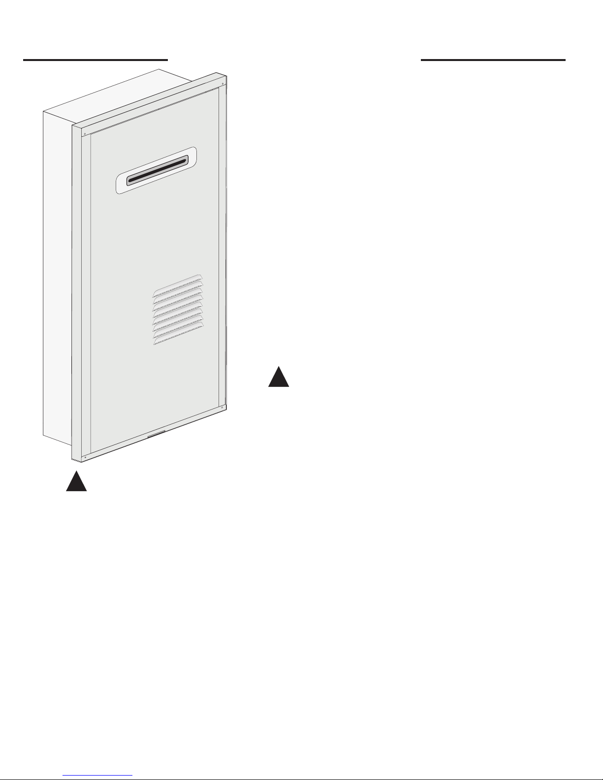
Tankless Water Heater Recess Box
Installation Instructions
Only these models of Outdoor Tankless Water Heaters
will t or function in this recess box;
RTG-53X RUTG-53X
RMTG-53X PTG-53X
PH-20ROF
The purpose of this manual is to provide the installer with
the basic instructions necessary to properly install the recess
box. This manual assumes that the installer has basic carpentry skills and plumbing knowledge. Local codes may
apply to this installation; all local building, electrical, and
plumbing codes should be followed.
It is very important that all persons who are expected to
install, operate or adjust this recess box and/or water heater,
read these instructions along with those instructions provided with the tankless water heater.
!
Refer to the Use and Care Manual provided with your
tankless water heater for the proper installation procedures and conditions.
!
WARNING!
paint thinners etc.), and the vapors they produce are extremely dangerous. DO NOT handle, use or store
gasoline or other ammable or combustible materials anywhere near or in the vicinity of a water heater
or any other appliance. Be sure to read and follow the labels on the water heater, as well as the warning
printed in this manual. Failure to do so can result in property damage, bodily injury or death.
Gasoline, as well as other ammable materials and liquids (adhesives, solvents,
Location - This water heater recess box is for OUT-
DOOR installation ONLY, and is intended for use only
with the water heater models listed above. Do not attempt
to install a water heater of another brand or model in this
recess box.
Do not attempt to modify this recess box. Doing so will
alter the intended design, potentially causing an unsafe
operating condition.
Consult the Use and Care Manual provided with your tankless water heater for installation instructions regarding a
suitable location for the water heater. All guidelines regard-
Recognize this symbol as an indication of Important
Safety Information!
ing clearances and distances from overhangs, windows and
doors, and air inlets into the home must be followed.
Recess Box Clearances - This recess box is de-
signed to be installed with a Zero (0) clearance to combustibles. For service and proper operation, 24” (61 cm) of
clearance is required in front of the recess box.
Freeze Protection - To help prevent water lines from
freezing do not locate water heater on the side of a building with prevailing winter winds. Refer to the Use and
Care Manual provided with your water heater for additional information.
1
AP14133 (12/06)
Page 2
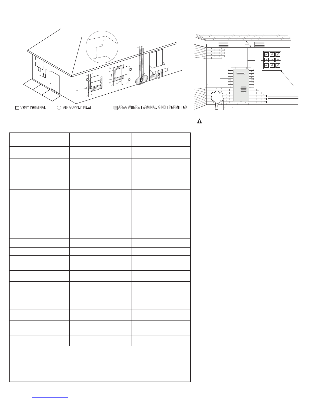
Recess Box Location - This water heater recess box is intended for an outdoor location only. Follow the
(1.8 m)
If soffit vent is too close,
block off and install new
vent at another location
Inside
corner
Caulk
Caulk
Caulk
6' (1.8 m)
caulk zone or
to edge of
window etc., starting
within 6' (1.8 m)
Rising moisture will collect under eaves
4'
6' (1.8 m) caulk
zone
6'
(1.2 m)
guidelines below or in the Use and Care Manual provided with the water heater for choosing a suitable location.
G
v
A
D
E
V
B
V
L
C
FI
v
L
C
P
O
v
F
B
B
D
E
X
D
E
S
O
B
E
L
B
A
R
E
I
F
E
L
L
C
B
A
R
E
P
O
v
v
J
B
A
H
C
D
v
E
X
D
E
S
O
X
I
M
v
X
K
Figure 1
VENT TERMINAL
V
AIR SUPPLY INLET
X
AREA WHERE TERMINAL IS NOT PERMITTED
Water Heater Exhaust Terminal Location
The following information should be used for determining the proper location of
the vent terminal for outdoor tankless water heaters.
Canadian Installations
Indoor and Outdoor
A= Clearance above grade, ve-
randa, porch, deck or balcony.
B= Clearance to window or door
that may be opened.
C= Clearance to permanently
closed window.
D= Vertical Clearance to venti-
lated soft located above the
terminal within a horizontal
distance of 2 feet (61 cm)
from the center line of the
terminal.
E= Clearance to unventilated
soft.
F= Clearance to outside corner.
G= Clearance to corner.
H = Clearance to each side of cen-
ter line extended meter/regulator assembly.
I = Clearance to service regulator
vent outlet.
J = Clearance to nonmechanical
air supply inlet to building or
the combustion air inlet to any
other appliance.
K = Clearance to mechanical air
supply inlet.
L = Clearance above paved
sidewalk or paved driveway
located on public property.
M = Clearance under veranda,
porch, deck or balcony.
1
In accordance with current CAN/CGA-B149 Installation Code
2
In accordance with current ANSI Z223.1/NFPA National Fuel Gas Code.
* If clearances are not specied, then follow local installation codes and the requirement of the gas supplier.
** For condensing appliances: The vent for this appliance shall not terminate over public walkways, near soft
vents, crawl space vents, or other areas where condensate or vapor could create a nuisance, hazard or cause
property damage, or where condensate or vapor could cause damage or could be detrimental to the operation
of regulators, relief valves or other equipment.
12 inches (30 cm) above anticipated snow level.
6 inches (15 cm) for appliances ≤
10,000 Btuh (3 kW), 12 inches (30
cm) for appliances > 10,000 Btuh
(3kW) and ≤100,000 Btuh (30kW),
36 inches (91 cm) for appliances >
100,000 Btuh (30kW).
* *
* *
* *
* *
* *
3 feet (91 cm) within a height 15
feet (4.57 m) above the meter/regulator assembly.
3 feet (91 cm)
6 inches (15 cm) for appliances
≤10,000 Btuh (3 kW), 12 inches
(30 cm) for appliances > 10,000
Btuh (3kW) and ≤ 100,000 Btuh
(30kW), 36 inches (91 cm) for appliances > 100,000 Btuh (30kW).
6 feet (1.83 m) 3 feet (91 cm) above if within 10
Not Allowed Not Allowed
Not Allowed Not Allowed
1
US Installations
Outdoor
12 inches (30 cm) above anticipated snow level.
6 inches (15 cm) for appliances
≤ 10,000 Btuh (3 kW), 9 inches
(23 cm) for appliances > 10,000
Btuh (3kW) and ≤ 50,000 Btuh
(15kW), 12 inches (30 cm)
for appliances > 50,000 Btuh
(15kW).
*
*
6 inches (15 cm) for appliances
≤10,000 Btuh (3 kW), 9 inches
(23 cm) for appliances > 10,000
Btuh (3kW) and ≤ 50,000 Btuh
(15kW), 12 inches (30 cm) for
appliances > 50,000 Btuh (15kW)
feet (3 m) horizontally.
2
Figure 2
WARNING: Moisture in the flue gas will condense as it
leaves the vent terminal. In cold weather this condensate can
2
freeze on the exterior wall, under the eaves and on
surrounding objects. Some discoloration to the exterior of
the building is to be expected. However, improper location
or installation can result in severe damage to the structure
or exterior finish of the building
Additional Considerations
1. Do not install water heater under
any patio or deck.
2. To help prevent moisture from freezing on walls and under eaves, do not
locate the water heater on the side
of a building with prevailing winter
winds.
3. To help prevent water lines from
freezing do not locate water heater
on the side of a building with prevailing winter winds.
4. Do not locate water heater too close
to shrubbery, as ue gases may damage them.
5. Caulk all cracks, seams and joints
within six (6) feet (1.8 m) of exhaust
vent.
6. Guard exhaust vent against accidental contact with people and pets.
7. Install the water heater such that the
air inlet and exhaust vent are above
anticipated snow levels
Page 3
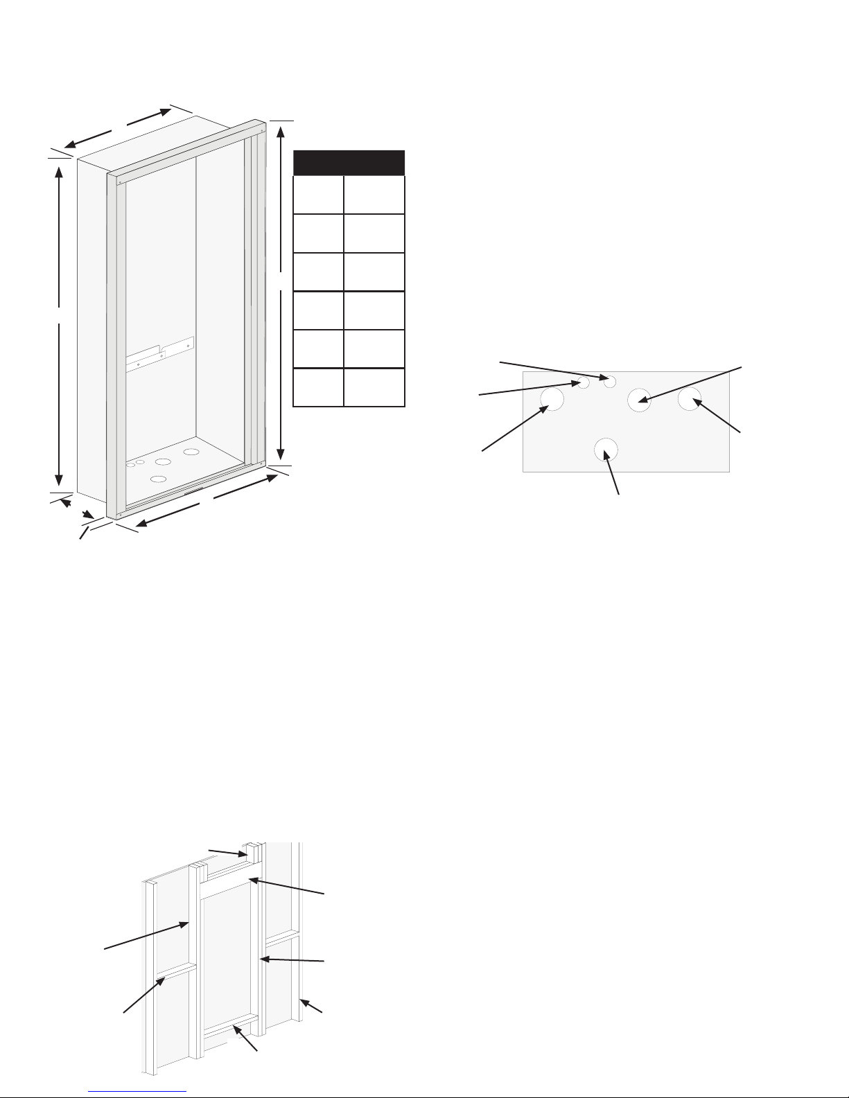
Rough In Dimensions
Height 36”; Width 15”; Depth depends upon siding on home.
Dimensions - Figure 3
B
Dim.* Inches
A 35
(89 cm)
B 14 3/4
(37 cm)
C 5 5/8
E
A
* Approximate
(14 cm)
D 1
(2.5 cm)
E 37 3/4
(96 cm)
F 18 3/4
(48 cm)
Install the recess box into the opening. Level and
2.
square the box. Test fit the outer door to make
sure it does not bind during installation. Secure
the recess box to the framing on each side using
four or more self tapping screws (not provided).
Mount the water heater into the recess box. In the back
3.
of the recess box is a channel to support the bottom
mounting bracket of the water heater. At the top is a
retaining stud for securing the top mounting bracket.
Lift the water heater up and slide the bottom mounting
bracket down into the channel. While holding the water
heater in place, secure the top of the unit to the retaining stud with the washer and nut provided.
Plumbing and Piping Openings - Figure 5
Thermostat
Wiring
Opening
Electrical
Opening
Cold Water
Line
Gas Line
C
D
F
Installation
The recess box is designed to be installed with a variety of
home exterior products for new or existing construction.
Choose a suitable location for the water heater and
1.
recess box. Follow the guidelines listed on page 2 of
this manual, or the Use and Care Manual for the water
heater, regarding location and clearances. Frame an
opening in the exterior wall of the home for the rough
in dimensions in Figure 3. Local building codes and
standard building practices should be followed.
Typical Framing - Figure 4
Cripple Stud
Header
Hot Water
Line
Relief Valve Drain
Plumbing and Piping -
See Figure 5 for Pipe Locations.
Follow all instructions in the Use and Care Manual for installation of gas and water lines. Holes are provided in the bottom of the recess box for all piping and wiring. These holes
line up with the ttings on the bottom of the water heater.
Stub the water lines and gas pipe up through the bottom
1.
of the box (See Figure 5). It is recommended that shut
off valves and unions be installed in the piping for
future service requirements.
Connect the water lines and gas piping to the water
2.
heater in accordance with the instructions in the Use
and Care Manual provided with the water heater.
Seal the holes around the piping with a silicone based
3.
sealant to prevent any water from leaking into the
wall behind the recess box. Insulate pipes with foam
insulation.
King Stud
Blocking
Sill
Trimmer Stud
Wall Stud
Power Disconnect - Install a suitable means to discon-
nect power from the unit for service. This disconnect should
be weather resistant and meet any and all local codes. In the
absence of local codes, the National Electrical Code should
be followed. Refer to the Use and Care Manual for instructions in connecting the power to the water heater.
3
Page 4
Thermostat Wiring - A hole is provided for
the Thermostat wire(s). Route the wire through the
hole and connect the wire to the water heater according to the instructions in the Use and Care Manual.
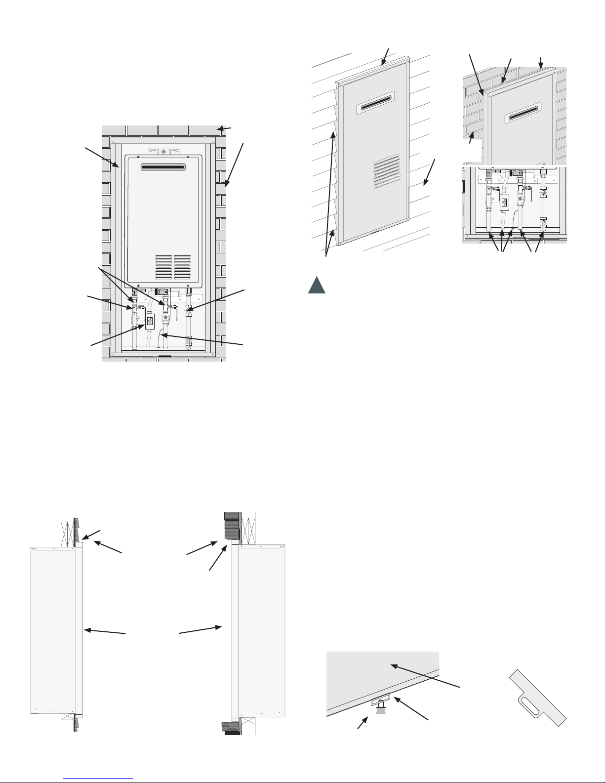
Typical Installation - Figure 6
Sealing and Finish - Figure 8
Drip Ledge
Caulk Joint Between Siding
and Recess Box
Wall Sheathing
(Brick, Vinyl, etc)
Recess Box
Outdoor
Tankless Water
Heater
Isolation Valves
Gas Service
Pressure
Relief Valve
Power Disconnect
Valve
Thermostat
Wire
Final Assembly and Inspection - Follow the
Use and Care Manual for complete details about the water
heater. Check all water and gas connections for leaks.
Typical Installation and Finish - Figure 7
Lap Siding
Drip Ledge
Siding or Brick
Brick Lintel
Recess Box
Brick Siding
Outer Door
Siding or Brick
Caulk Joint Between Siding
and Recess Box
!
Warning - All openings in the bottom of the recess box
Seal all openings around pipes
and wires with a silicone sealant
must be sealed to prevent water inltration in to the wall. Failure to do so could result in damage to the wall.
Seal all openings around pipes and wires with an outdoor
grade silicone sealant. Seal the joint between the recess box
and the siding or brick of the house with a silicone based sealant to prevent water from getting behind the box into the wall.
Installing the Door - Lift the door up from the bot-
tom at a slight angle. Slip the door into the channel at the
top of the recess box. Next push the bottom of the door
ush with the recess box and slide down into the channel
at the bottom of the enclosure. Do not block any air openings on the door.
Security Clip - Before installing the door, slide the
clip into the slot at the bottom of the door from the backside so it points straight down through the bottom of the
door. Lift the door into place per the instruction above. As
the door is being slid down into place, guide the security
clip into the slot in the bottom channel of the recess box.
Once the clip is in place, secure with a suitable means
(small padlock, security tag, etc.).
Security Clip - Figure 9
Outer Door
Padlock
Security Clip
4
 Loading...