

Page 1
92-22876-27-00
INSTALLATION INSTRUCTIONS
FOR (-)OBF UPFLOW OIL FIRED FURNACES
IMPORTANT: Do not use a power-
robbing electronic thermostat with
this furnace. Use only mechanical
thermostats or battery powered
electronic thermostats.
U.L. recognized fuel gas and CO (carbon monoxide) detectors are recommended in
all applications, and their installation should be in accordance with the
manufacturer’s recommendations and/or local laws, rules, regulations, or customs.
ISO 9001:2000
— Do not store or use gasoline or other flammable vapors and liquids, or other
combustible materials in the vicinity of this or any other appliance.
— WHAT TO DO IF YOU SMELL FUEL OIL VAPORS
• Do not try to light any appliance.
• Do not touch any electrical switch; do not use any phone in your building.
• Immediately call your fuel oil supplier from a neighbor’s phone. Follow the fuel
oil supplier’s instructions.
• If you cannot reach your fuel oil supplier, call the fire department.
• Do not return to your home until authorized by the fuel oil supplier or
fire department.
— DO NOT RELY ON SMELL ALONE TO DETECT LEAKS. DUE TO VARIOUS
FACTORS, YOU MAY NOT BE ABLE TO SMELL FUEL GASES.
• U.L. recognized fuel gas and CO detectors are recommended in all applications,
and their installation should be in accordance with the manufacturer’s
recommendations and/or local laws, rules, regulations, or customs
— Improper installation, adjustment, alteration, service or maintenance can cause
injury, property damage or death. Refer to this manual. Installation and service must
be performed by a qualified installer, service agency or the fuel oil supplier.
Page 2

2
IMPORTANT: TO ENSURE PROPER INSTALLATION AND OPERATION OF
THIS PRODUCT, COMPLETELY READ ALL INSTRUCTIONS PRIOR TO
ATTEMPTING TO ASSEMBLE, INSTALL, OPERATE, MAINTAIN OR REPAIR
THIS PRODUCT. ADDITIONALLY, UPON UNPACKING OF FURNACE,
INSPECT ALL PARTS FOR DAMAGE PRIOR TO INSTALLATION AND START
UP.
CONTENTS
SAFETY RULES...................................................................................................3
LOCATION REQUIREMENTS AND CONSIDERATIONS ...................................4
GENERAL INFORMATION ..................................................................................4
Dimensions and Clearances .............................................................................4
Blower Performance Data.................................................................................5
Oil Furnace Specifications ................................................................................5
Selecting Nozzle Size .......................................................................................6
INSTALLATION INSTRUCTIONS........................................................................7
Requirements....................................................................................................7
Location ............................................................................................................7
Combustion Air Supply..........................................................................................7
Circulating Air Supply........................................................................................9
Flue and Chimney Exhaust...............................................................................9
Chimney Size Recommendations.....................................................................9
Venting..............................................................................................................9
Barometric Draft Control .................................................................................10
Oil Burner / Primary Control............................................................................10
Tank and Oil LInes..........................................................................................11
Electric Wiring .................................................................................................11
Thermostat......................................................................................................11
Typical Installation Diagrams ..........................................................................12
Heat Anticipator Settings ................................................................................13
OPERATING INSTRUCTIONS...........................................................................13
Lighting Instructions ........................................................................................13
FURNACE ADJUSTMENT .................................................................................14
Burner Adjustment ..........................................................................................14
Oil Pump/Pump Bleeding and Checking Pump Pressure ...............................16
Electrode Adjustment......................................................................................17
Air Volume Adjustments..................................................................................17
Fan/Limit Control.............................................................................................19
MAINTENANCE..................................................................................................20
Burner Maintenance........................................................................................20
Lubrication ......................................................................................................20
Air Filter...........................................................................................................20
Draft Problems/Troubleshooting .....................................................................21
Oil Burner Data ...............................................................................................22
Troubleshooting ..............................................................................................23
Furnace Adjustment Check Sheet ..................................................................27
WIRING DIAGRAMS ..........................................................................................28
INSTALLER: HANG THESE INSTRUCTIONS
ADJACENT TO FURNACE
HOMEOWNER: KEEP THESE INSTRUCTIONS
FOR FUTURE REFERENCE
Page 3

3
DO NOT USE THIS FURNACE IF ANY
PART HAS BEEN UNDER WATER. A
FLOOD-DAMAGED FURNACE IS
EXTREMELY DANGEROUS.
ATTEMPTS TO USE THE FURNACE
CAN RESULT IN FIRE OR
EXPLOSION. A QUALIFIED SERVICE
AGENCY SHOULD BE CONTACTED
TO INSPECT THE FURNACE AND TO
REPLACE ALL GAS CONTROLS,
CONTROL SYSTEMS PARTS,
ELECTRICAL PARTS THAT HAVE
BEEN WET OR THE FURNACE, IF
DEEMED NECESSARY.
THIS FURNACE IS DESIGN
CERTIFIED TO OPERATE ON #2
FUEL OIL. DO NOT ATTEMPT TO
CONVERT THIS FURNACE TO
BURN NATURAL GAS OR LP GAS.
FAILURE TO FOLLOW THIS
WARNING CAN CAUSE A FIRE OR
EXPLOSION RESULTING IN
PROPERTY DAMAGE, PERSONAL
INJURY OR DEATH.
1. Do not install this furnace in a
mobile home, trailer or
recreational vehicle.
2. Keep area around furnace free
and clear of combustible materials
including gasoline and other
flammable vapors and liquids.
3. Do not use furnace area for
storage purposes or as a broom
closet.
4. This furnace must be vented
through a good chimney to carry
combustion products outdoors as
described under the VENTING
INSTALLATION section of this
manual.
5. Provide adequate ventilation to the
furnace area.
6. IMPORTANT: Make sure supply
and return air ducts are sealed to
the furnace casing. These ducts
must be entirely separated from
area supplying combustion and
ventilation air.
7. Disconnect electrical power before
servicing appliance.
8. Install this furnace only in a
location and position as specified
in the general information section
of these instructions. Provide
adequate combustion and
ventilation air to the furnace space
as specified in the venting section
of these instructions.
9. Provide adequate combustion and
ventilation air to the furnace space
as specified in venting section of
these instructions.
10. Combustion products must be
discharged outdoors. Connect this
furnace to an approved vent
system only, as specified in the
venting section of these
instructions.
11. Always install furnace to operate
within the furnace’s intended
temperature-rise range with a duct
system which has an external
static pressure within the
allowable range, as specified in
general information section of
these instructions. See furnace
rating plate.
12. When a furnace is installed so that
supply ducts carry air circulated by
the furnace to areas outside the
space containing the furnace, the
return air shall also be handled by
duct(s) sealed to the furnace
casing and terminating outside the
space containing the furnace.
13. The furnace is not to be used for
temporary heating of buildings or
structures under construction.
Important: All Rheem products meet
current Federal OSHA Guidelines for
safety. California Proposition 65
warnings are required for certain
products, which are not covered by the
OSHA standards.
California's Proposition 65 requires
warnings for products sold in California
that contain, or produce, any of over
600 listed chemicals known to the State
of California to cause cancer or birth
defects such as fiberglass insulation,
lead in brass, and combustion products
from natural gas.
All “new equipment” shipped for sale in
California will have labels stating that
the product contains and/or produces
Proposition 65 chemicals. Although we
have not changed our processes,
having the same label on all our
products facilitates manufacturing and
shipping. We cannot always know
“when, or if” products will be sold in the
California market.
You may receive inquiries from
customers about chemicals found in, or
produced by, some of our heating and
air-conditioning equipment, or found in
natural gas used with some of our
products. Listed below are those
chemicals and substances commonly
associated with similar equipment in
our industry and other manufacturers.
• Glass Wool (Fiberglass) Insulation
• Carbon Monoxide (CO)
• Formaldehyde
• Benzene
More details are available at the
Websites for OSHA (Occupational
Safety and Health Administration), at
www.osha.gov
and the State of
California's OEHHA (Office of
Environmental Health Hazard
Assessment), at www.oehha.org.
Consumer education is important since
the chemicals and substances on the
list are found in our daily lives. Most
consumers are aware that products
present safety and health risks, when
improperly used, handled and
maintained.
SAFETY RULES
WARNING
!
WARNING
!
Page 4
4
HELPFUL INFORMATION
The following national standards will
help you in making this installation.
Current editions of these standards
should be obtained from:
American National Standards Institute
1430 Broadway
New York, NY 10018
National Electric Code
ANSI/NFPA No. 70
National Fire Protection Association,
Inc.
Batterymarch Park
Quincy, MA 02269
Installation of Oil Burning
Equipment
NFPA No. 31
Installation of Air Conditioning and
Ventilating Systems
NFPA No. 90A
Warm Air Heating and Air
Conditioning Systems
NFPA No. 90B
Standard for Chimneys, Fireplaces,
Vents, and Solid Fuel-Burning
Appliances NFPA No. 211
LOCATION REQUIREMENTS AND CONSIDERATIONS
GENERAL INFORMATION
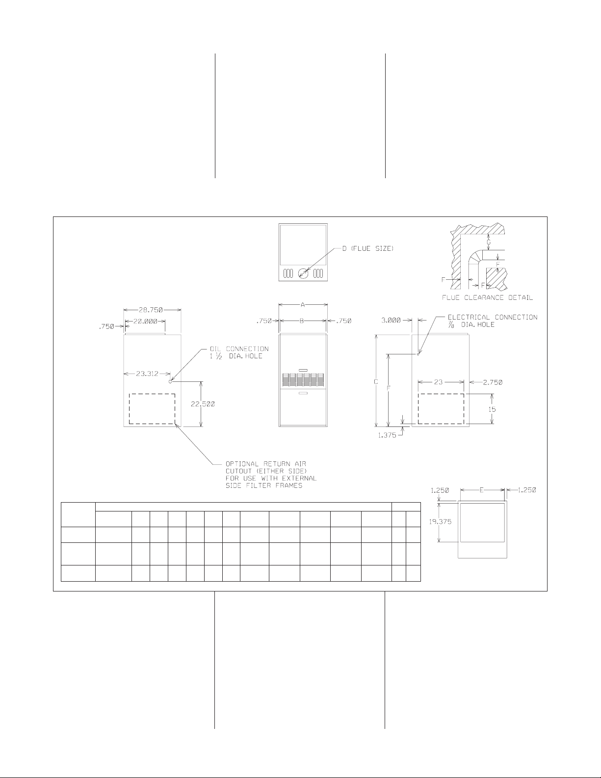
FIGURE 1
DIMENSIONS AND
CLEARANCES TO COMBUSTIBLES
a0965
RETURN
AIR
TOP VIEW
SUPPLY
RIGHT SIDE VIEW
OPTIONAL RETURN
BOTTOM DETAIL
RETURN
FRONT VIEW
LEFT SIDE VIEW
MODEL
HEATING
CAPACITY
LEFT
SIDE
RIGHT
SIDE
BACK FRONT TOP F
FLUE
G
ABCDEF
DIMENSIONS REDUCED CLEARANCES (IN.)
-067 56.000
21 19
1
⁄2 46 5 181⁄2 333⁄4 11 1 8 348
67.200
84000
-112 95200 24
1
⁄2 23 46 5 22 333⁄4 11 1 8 348
112000
-150 134400
28 26
1
⁄2 49 7 251⁄2 361⁄4 11 1 8 348
151200
SUPPLY
AIR
Page 5
5
TABLE 1
BLOWER PERFORMANCE DATA
TABLE 2
UPFLOW OIL FURNACE SPECIFICATIONS
MODEL
NUMBER
HEATING
CAPACITY
(BTU/H)
[KW]
BLOWER
SIZE
MOTORHPBLOWER
SPEED
CFM AIR DELIVER
E.S.P. INCHES WATER COLUMN
0.5 0.4 0.3 0.2
NOZZLE
SIZES
(GPH)
HEATING
SPEED
COOLING
SPEED
56000 HIGH 1140 1190 1230 1260
-067
[16.41KW]
10 X 7 1/4
MED-HIGH 15 940 955 970
0.5 MED-LOW HIGH
67200 MED-LOW 795 835 870 885
[19.69KW] LOW 600 620 635 645
0.65 MED-HIGH HIGH
84000
[24.62KW] HIGH 1500 1575 1645 1705
0.75 LOW HIGH
-112
95200
10 X 10 1/2
MED-HIGH 1375 1430 1480 1530
0.85 MED-LOW HIGH
[27.90KW] MED-LOW 1230 1260 1285 1300
112000 LOW 1040 1065 1080 1090
1.00 MED-HIGH HIGH
[32.83KW]
134400 HIGH 2070 2110 2145 2175
-150
[39.38KW]
11 X 10 3/4
MED-HIGH 1715 1745 1760 1770
1.20 MED-HIGH HIGH
151200 MED-LOW 1375 1400 1435 1450
[44.30KW] LOW 1045 1055 1070 1090
1.35 HIGH HIGH
MODEL
NUMBER
-067 -112 -150
56000 [16.41KW]
84000 [24.62KW]
134400 [39.38 KW]
HEATING CAPACITY (BTU/H) [KW] 95200 [27.90KW]
67200 [19.69KW]
112000 [32.83KW]
151200 [44.30KW]
BLOWER MOTOR DRIVE DIRECT DIRECT DIRECT
BLOWER DIA. x WIDTH 10 x 7 10 x 10 11 x 10
MOTOR H.P. (NO. OF SPEEDS) 1/4 (4) 1/2 (4) 3/4 (4)
WIDTH 21 24
1
⁄2 28
DEPTH 28
3
⁄4 283⁄4 283⁄4
HEIGHT 46 46 49
FILTER RACK RXGF- Z16B Z16B Z16B
HEATING EXT. STATIC PRESSURE 2 2 2
MAX. EXTERNAL STATIC PRESSURE .5 .5 .5
TEMPERATURE RISE RANGE F 40-70 50-80 60-90
BLOWER MOTOR FULL LOAD AMPS 5.7 8.7 11.0
TOTAL CURRENT 7.5 14.1 16.1
MINIMUM CIRCUIT AMPACITY 11.6 16.3 18.8
FLUE SIZE—DIA. 5" 5" 7"
AIR DELIVERY (HEATING/COOLING) 915/1140 1375/1500 1715/2070
AIR FILTER SIZE (QTY.) (1) 16 x 25 x 1 (1) 16 x 25 x 1 (1) 16 x 25 x 1
APPROX. SHIP WT. (LBS.) 160 198 207
Page 6
6
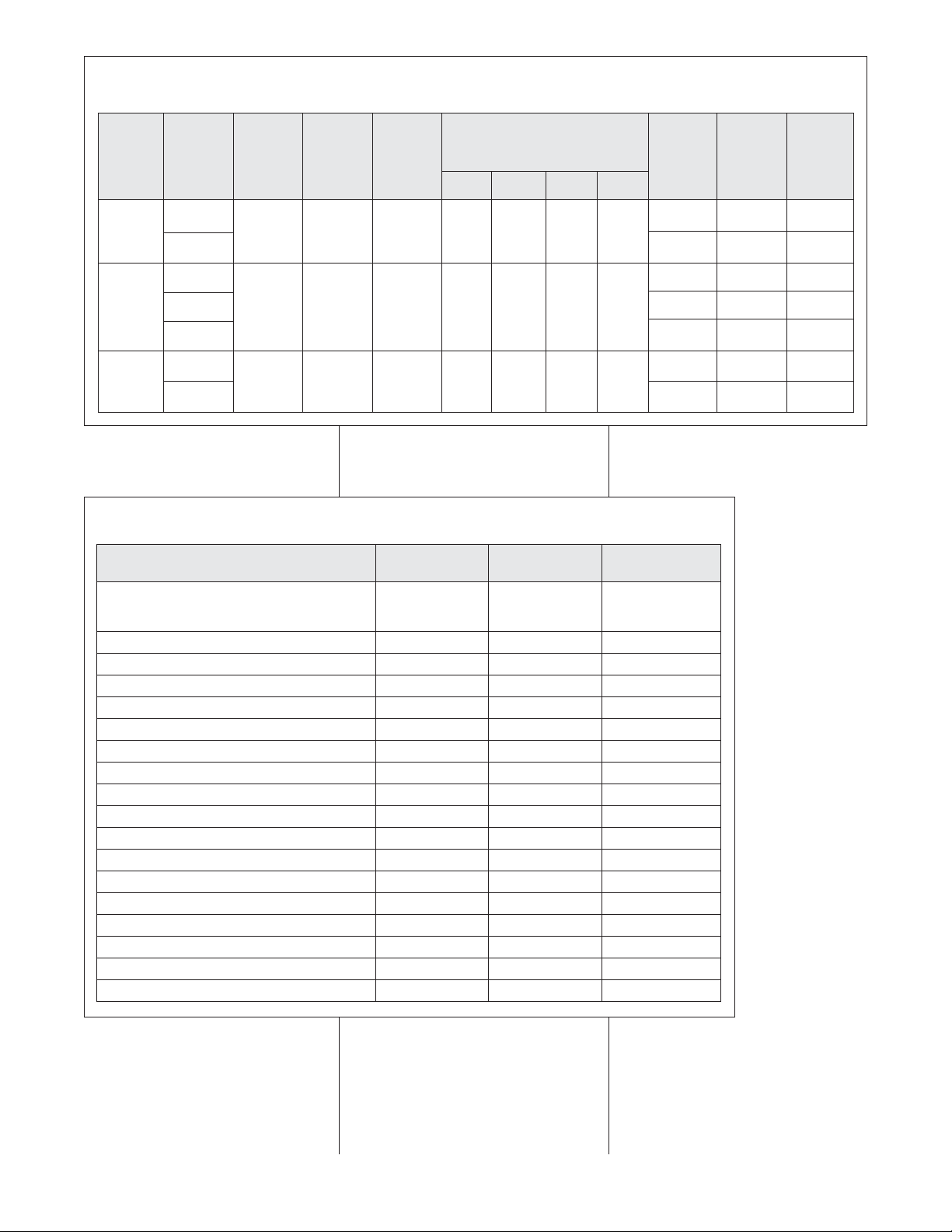
TABLE 3
UPFLOW HEATING CAPACITY
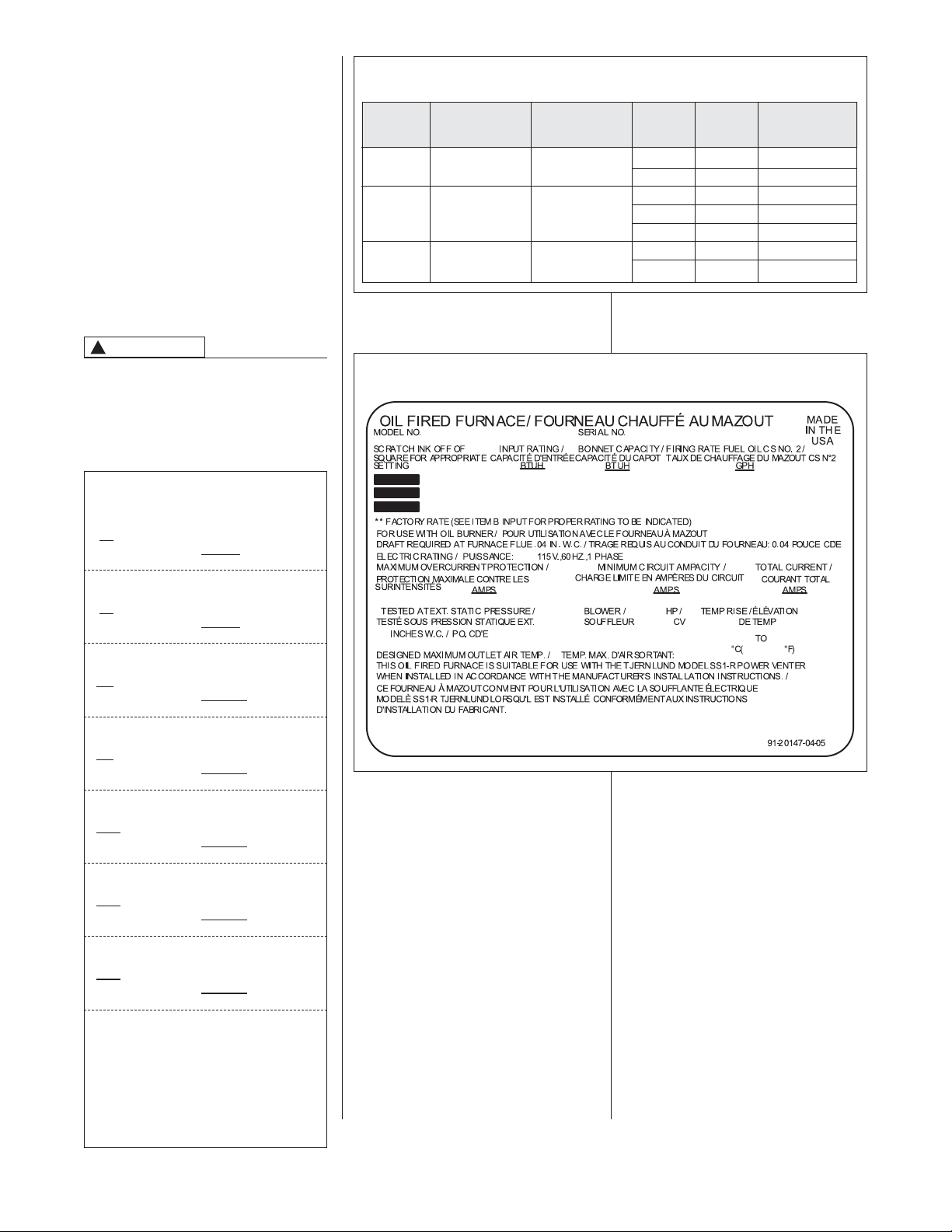
FIGURE 2
TYPICAL RATING PLATE INFORMATION
SELECTING NOZZLE SIZE
All furnaces are capable of firing at
multiple rates (see Table 3). The
furnaces are shipped with the highest
heat output rate nozzle installed.
Smaller nozzles are included in the
parts bag, shipped with the furnace.
Select the appropriate nozzle by
determining the load requirements of
the house and comparing it to the Net
Input (see Table 3). If the load is
greater than the Net Input for the
nozzle, select the next highest nozzle
size. Use Table 1 to select the
appropriate flow speed for the nozzle
size selected.
NOZZLE CHANGES/INPUT RATE
DETERMINATION SHOULD ONLY
BE MADE BY A QUALIFIED
SERVICE TECHNICIAN.
CAUTION
!
FIGURE 3
THIS FURNACE WAS INSTALLED WITH
A NOZZLE HAVING A FIRING RATE OF
.50
GALLONS PER HOUR AND AN
INPUT RATING OF 70,000 BTUH.
92-100538-01A-00
THIS FURNACE WAS INSTALLED WITH
A NOZZLE HAVING A FIRING RATE OF
.60 GALLONS PER HOUR AND AN
INPUT RATING OF 84,000 BTUH.
92-100538-01B-00
THIS FURNACE WAS INSTALLED WITH
A NOZZLE HAVING A FIRING RATE OF
.75
GALLONS PER HOUR AND AN
INPUT RATING OF 105,000
BTUH.
92-100538-01C-00
THIS FURNACE WAS INSTALLED WITH
A NOZZLE HAVING A FIRING RATE OF
.85 GALLONS PER HOUR AND AN
INPUT RATING OF 119,000 BTUH.
92-100538-01D-00
THIS FURNACE WAS INSTALLED WITH
A NOZZLE HAVING A FIRING RATE OF
1.00 GALLONS PER HOUR AND AN
INPUT RATING OF 140,000 BTUH.
92-100538-01E-00
THIS FURNACE WAS INSTALLED WITH
A NOZZLE HAVING A FIRING RATE OF
1.20 GALLONS PER HOUR AND AN
INPUT RATING OF 168,000 BTUH.
92-100538-01F-00
THIS FURNACE WAS INSTALLED WITH
A NOZZLE HAVING A FIRING RATE OF
1.35
GALLONS PER HOUR AND AN
INPUT RATING OF 189,000 BTUH.
92-100538-01G-00
INSTRUCTIONS:
PEEL OFF APPROPRIATE LABEL AND APPLY
ADJACENT TO FURNACE RATING LABEL. FIRING
RATE AND INPUT RATING ON LABEL MUST
AGREE WITH THE ACTUAL FIRING RATE AND
INPUT RATING OF THE FURNACE AS INSTALLED.
DISCARD REMAINING LABELS.
92-100538-01-00
NOTE:
When installing the furnace, be sure to
mark the appropriate firing rate/nozzle
size on the rating label (see Figure 2)
by scratching the surface off of the
appropriate square. The appropriate
label from sheet 92-100538-01 (see
Figure 3) must also be applied near the
rating plate.
MODEL
NUMBER
DELAVAN
NOZZLE
SIZES
DEL-O-FLO
NOZZLE
SIZES
GROSS
INPUT
(BTUH)
NET
INPUT
(BTUH)
AFUE
(ISOLATED
COMBUSTION)
70,000 58,000 82.9%
-067 — (.50, .65) - 70°B
84,000 67,000 80.8%
105,000 86,100 82.0%
-112 (1.0) -70°B (.75, .85) - 70°B 119,000 96,900 81.4%
140,000 112,000 80.0%
-150 (1.2, 1.35) - 70°B —
168,000 136,000 81.0%
189,000 154,000 81.5%
Page 7
7
REQUIREMENTS
IMPROPER INSTALLATION,
ADJUSTMENT, ALTERATION,
SERVICE OR MAINTENANCE CAN
CAUSE PROPERTY DAMAGE,
INJURY OR DEATH. CONSULT A
QUALIFIED INSTALLER OR
SERVICE AGENCY FOR SERVICE
AND ASSISTANCE.
The furnace should be installed in
accordance with the latest editions of
the NFPA 31 booklet, “Installation of
Oil Burning Equipment,” the NFPA 90B
booklet, “Warm Air Heating and Air
Conditioning Systems” the NFPA 90A
booklet, “Installation of Venting and Air
Conditioning Systems” and the NFPA
211 booklet “Standard for Chimneys,
Fireplaces, Vents, and Solid FuelBurning Appliances” published by the
National Fire Protection Association,
Batterymarch Park, Quincy, MA 02269.
THIS FURNACE IS DESIGN
CERTIFIED TO OPERATE ON #2
FUEL OIL. DO NOT ATTEMPT TO
CONVERT THIS FURNACE TO
BURN NATURAL GAS OR LP GAS.
FAILURE TO FOLLOW THIS
WARNING CAN CAUSE A FIRE OR
EXPLOSION RESULTING IN
PROPERTY DAMAGE, PERSONAL
INJURY OR DEATH.
LOCATION
THIS FURNACE IS NOT APPROVED
FOR INSTALLATION IN A MOBILE
HOME. DO NOT INSTALL THIS
FURNACE IN A MOBILE HOME.
INSTALLATION IN A MOBILE HOME
COULD CAUSE FIRE, PROPERTY
DAMAGE AND PERSONAL INJURY
OR DEATH.
Locate furnace as close to chimney as
practical, giving considerations to duct
trunk lines and accessibility of oil
burner, controls, blower and filter. For
basement installation, if there is no
level concrete floor or if water may be
encountered, a level concrete base
should be provided. Allow a minimum
of twenty-four inches at front of furnace
for servicing oil burner and controls.
Fire protection clearances are printed
in figure 1 and on the rating plate of the
furnace.
An oil-fired furnace installed in a
residential garage must be located or
protected to avoid physical damage by
vehicles.
This furnace is approved for installation
indoors only. Do not install unit
outdoors.
COMBUSTIBLE MATERIAL MUST
NOT BE PLACED ON OR AGAINST
THE FURNACE JACKET. THE AREA
AROUND THE FURNACE MUST BE
KEPT CLEAR AND FREE OF ALL
COMBUSTIBLE MATERIAL
INCLUDING GASOLINE AND OTHER
FLAMMABLE VAPOR OR LIQUIDS.
THE HOMEOWNER SHOULD BE
CAUTIONED THAT THE FURNACE
AREA MUST NOT BE USED AS A
BROOM CLOSET OR FOR ANY
OTHER STORAGE PURPOSES.
COMBUSTIBLE MATERIAL PLACED
AGAINST FURNACE JACKET COULD
CAUSE FIRE, PROPERTY DAMAGE,
PERSONAL INJURY OR DEATH.
COMBUSTION AIR SUPPLY
THIS FURNACE MUST BE PROVIDED
WITH ENOUGH FRESH AIR FOR
PROPER COMBUSTION AND
VENTILATION OF FLUE GASES.
SOME HOMES MAY REQUIRE THAT
OUTSIDE AIR BE SUPPLIED TO THE
FURNACE AREA. FAILURE TO
PROVIDE ENOUGH FRESH AIR CAN
CAUSE DEATH FROM CARBON
MONOXIDE POISONING.
Adequate facilities for combustion and
ventilation must be provided in
accordance with section number 1-5,
“Air for Combustion and Ventilation,” of
the
Standard for Installation of Oil
Burning Equipment, NFPA No. 31
, latest
edition or other applicable provisions of
local building codes. The flow of combustion air to the furnace area must not
be obstructed.
Important: Air for combustion and
ventilation must not come from a
corrosive atmosphere. Any failure due
to corrosive elements in the atmosphere
is excluded from warranty coverage.
Combustion air must be free of acidforming chemicals such as sulphur,
fluorine and chlorine. These elements
are found in aerosol sprays, detergents,
bleaches, cleaning solvents, air
fresheners, paint and varnish removers,
refrigerants and many other commercial
and household products. Vapors from
these products when burned in a flame
form acidic compounds and are highly
corrosive when they condense.
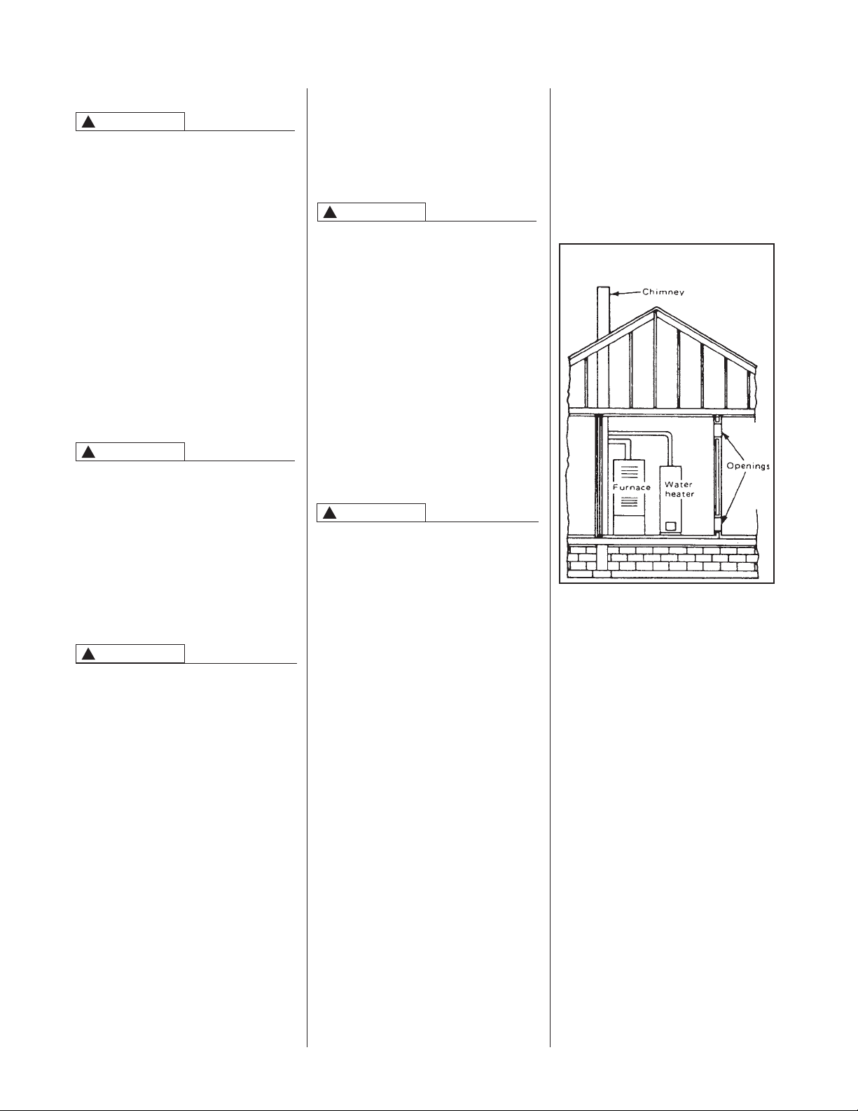
When appliances are installed within a
confined space and combustion air is
taken from within the heated space, the
air supply must be through two
permanent openings of equal area, one
located within 12 inches of the ceiling
and one within 12 inches of the floor
(see figure 4). Refer to the rating plate
label on the furnace for information on
the minimum free area of these two
openings.
When appliances are installed in an
unconfined space in a building of conventional frame, brick or stone
construction, infiltration normally is
adequate to provide for combustion
ventilation and draft control dilution. If
the unconfined space is within a
building of unusually tight construction,
a supply of combustion, ventilation and
draft control dilution air must be
obtained from outdoors or spaces freely
connected to the outdoors. Under these
conditions a permanent opening or
openings having a total free area of not
less than 1 sq. in. per 5,000 BTUH of
total input rating of all appliances shall
be provided. This code is found in
NFPA 31, Standard for Installation of
Oil Burning Equipment
. Other State,
Provincial, and Local codes may apply,
check with local inspectors.
When appliances are installed in a
confined space within a building of
unusually tight construction, air for
combustion must be obtained from
outdoors or from spaces or ducts freely
drawing from the outdoors. Under these
INSTALLATION INSTRUCTIONS
WARNING
!
WARNING
!
WARNING
!
WARNING
!
FIGURE 4
OPENINGS FOR CONFINED SPACES
WARNING
!
Page 8
8
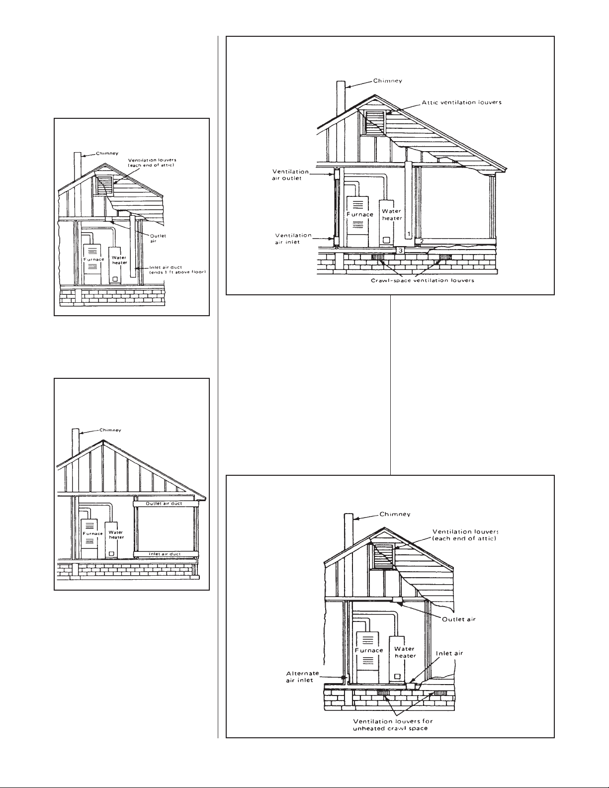
conditions, two openings of
approximately equal area (one located
near the top and one located near the
bottom of the enclosure) must be
provided each with a total free area of not
less than 1 square inch per 4,000 BTU’s /
Hr. of total input rating of all appliances in
the enclosure (see figure 5).
If horizontal ducts are used, each
opening shall have a free area of not
less than 1 sq. in. per 2,000 BTUH of
total input of all appliances in the
enclosure (see figure 6).
Appliances installed in confined
spaces may be installed with ventilation
air from inside the building and
combustion air from outdoors. Consult
state and local codes and the
NFPA
No. 31, Standard for Installation of Oil
Burning Equipment
for specific details
(see figure 7 for an example).
Appliances installed in confined
spaces with all required air coming
from the outdoors may also get inlet
air from continuously ventilated crawl
spaces and outlet air to a ventilated
attic (see figure 8).
"NFPA 31, Standard for Installation of
Oil Burning Equipment"
defines
"confined space" and "unconfined
space" as follows.
Confined Space - Any space whose
volume is less than 50 cu. ft. per 1,000
BTUH of the aggregate input rating of
all fuel-burning appliances installed
therein.
Unconfined Space - Any space whose
volume is equal to or greater than 50
cu. ft. per 1,000 BTUH of the aggregate
input rating of all fuel-burning
appliances installed therein. Rooms
connecting directly with the space in
which the appliances are located by
means of openings that have no doors
or closures, unless fully louvered, shall
be considered part of the unconfined
space.
When determining if the furnace is
located in a confined or unconfined
space it is important to realize that
some buildings are so tight that normal
infiltration does not meet air
requirements for proper combustion or
venting and outside air must be
introduced.
Important: All applicable codes must
be followed when providing air to the
confined space.
FIGURE 5
ALL AIR FROM VENTILATED ATTIC
FIGURE 6
DIRECTLY CONNECTING HORIZONTAL
DUCTS TO OUTDOORS
FIGURE 7
INSIDE VENTILATION AIR, OUTSIDE
COMBUSTION AIR
FIGURE 8
OUTSIDE AIR FROM ATTIC AND CRAWL SPACE
Page 9
9
CIRCULATING AIR SUPPLY
Plenum chambers and air ducts must
be installed in accordance with the
Standard for the Installation of Air
Conditioning and Ventilating Systems,
NFPA No. 90A, or the Standard for the
Installation of Warm Air Heating and
Air Conditioning Systems, NFPA No.
90B.
The circulating air supply may be
taken: (1) exclusively from return air
ducts from several rooms, or (2)
combined with outside air. When
outside air is utilized, the system
should be designed and adjusted such
that the temperature of the combined
return air to the furnace will not be
below 50°F during the heating season.
When using a combination of outside
air and return air, be sure the ducts are
so designed and a diverting damper so
installed that the volume of circulating
air entering the furnace cannot be
reduced or restricted below that which
would normally enter through the
circulating air intake of the furnace.
When the furnace is installed so that
the supply ducts carry air circulated by
the furnace to areas outside the space
containing the furnace, the return air
shall be handled by a duct or ducts
sealed to the furnace casing and
terminated outside the space
containing the furnace.
IF THERE IS NO COMPLETE
RETURN AIR DUCT SYSTEM, THE
RETURN AIR CONNECTION MUST
RUN FULL SIZE TO A LOCATION
OUTSIDE THE UTILITY ROOM OR
SPACE HOUSING THE FURNACE
TO PREVENT A NEGATIVE
PRESSURE ON THE VENTING
SYSTEMS. A NEGATIVE PRESSURE
CAN DRAW PRODUCTS OF
COMBUSTION INTO CIRCULATING
AIR.
NEVER ALLOW THE PRODUCTS OF
COMBUSTION OR THE FLUE
PRODUCTS TO ENTER THE RETURN
AIR DUCTWORK OR THE
CIRCULATING AIR SUPPLY. ALL
RETURN DUCTWORK MUST BE
ADEQUATELY SEALED AND
SECURED TO THE FURNACE WITH
SHEET METAL SCREWS, AND
JOINTS TAPED. ALL OTHER DUCT
JOINTS MUST BE SECURED WITH
APPROVED CONNECTIONS AND
SEALED AIRTIGHT.
FAILURE TO PREVENT PRODUCTS
OF COMBUSTION FROM BEING
CIRCULATED INTO THE LIVING
SPACE CAN CREATE SOOT
DAMAGE, SMOKE, ODORS OR
CARBON MONOXIDE POISONING.
IMPORTANT: One of the most
common causes of trouble in forced air
heating systems is insufficient return
air to the furnace. The return air
system should be approximately equal
to or greater than the area of the warm
air discharge. CONSULT LOCAL
CODES FOR SPECIAL
REQUIREMENTS.
DO NOT, UNDER ANY
CIRCUMSTANCES, CONNECT
RETURN OR SUPPLY DUCTWORK
TO OR FROM ANY OTHER HEAT
PRODUCING DEVICE SUCH AS A
FIREPLACE INSERT, STOVE, ETC.
DOING SO MAY RESULT IN FIRE,
CARBON MONOXIDE POISONING,
EXPLOSION, PERSONAL INJURY,
PROPERTY DAMAGE OR DEATH.
Install the cold air return to terminate
through the floor under the furnace. A
direct connection should be made to
the bottom of the furnace. For
installations where return air ducts
cannot be run under the floor, return air
may be taken from the sides by cutting
the furnace casing and installing the
appropriate accessory.
NOTE: Where the maximum air flow is
1800 CFM or more, both sides or the
bottom must be used for return air.
When a cooling coil is used in
conjunction with the furnace, it must be
installed downstream of the outlet end
of the furnace (supply-air side) or in
parallel with the furnace to avoid
condensation in the heat exchanger.
If the furnace is installed in parallel with
a cooling unit, the damper or other
means used to control the flow of air
must be adequate to prevent chilled air
from entering the furnace, and if
manually operated must be equipped
with means to prevent operation of the
other unit unless the damper is in the
full heat or cool position.
IMPORTANT: Air openings in the
casing front, return air grilles and warm
air registers must not be obstructed.
BLOWER AND BURNERS MUST
NEVER BE OPERATED WITHOUT
BLOWER DOOR IN PLACE. THIS IS
TO PREVENT DRAWING FUMES
(WHICH COULD CONTAIN
ANNOYING AND HAZARDOUS
GASES) INTO THE HOME THAT
COULD RESULT IN PERSONAL
INJURY OR DEATH.
FLUE AND CHIMNEY
EXHAUST
The vent connector should be as short
as possible and installed so that it has
a continuous rise from the furnace to
the chimney or flue.
The number of elbows should be
minimized and the flue pipe should be
joined with sheet metal screw and
properly supported with suitable pipe
hangers.
A barometric draft regulator is required
in each furnace vent connector and
must be installed before the vent
connector enters the chimney or flue.
NOTE: The size of the draft regulator
diameter must be no smaller than the
vent connector diameter.
The vent connector should be the
same size as the furnace flue pipe
connection. The sizes are:
CHIMNEY SIZE
RECOMMENDATIONS
The following table shows
recommended size and height for
chimneys based on total BTU input of
all the oil appliances being vented:
VENTING
Unit must be vented through a chimney
or flue. Check chimney for soot, leaks,
obstruction and proper height to
prevent down draft. Clean chimney and
base if necessary.
The height of the chimney or flue shall
be at least 3 feet above the highest
point where it passes through the roof
of a building and at least 2 feet higher
than any portion of a building within 10
feet of such chimney.
WARNING
!
WARNING
!
WARNING
!
TABLE 5
GROSS BTU RECTANGULAR ROUND MINIMUM
INPUT TILE TILE HEIGHT
(INCHES) (INCHES) (FEET)
144,000 8
1
/2 x 81/2 820
235,000 8
1
/2 x 13 10 30
372,000 13 x 13 12 35
516,000 13 x 18 14 40
612,000 — 15 45
768,000 18 x 18 — 50
960,000 20 x 20 18 55
BTU OUTPUT FLUE SIZE
056
067
084
095
112
130
150
5”
5”
5”
5”
5”
7”
7”
TABLE 4
Page 10
10
Install a single wall, vent connector
from flue outlet to chimney, sloping flue
pipe continuously upward (at least 1/4
inch per foot) toward chimney. The
vent connector should be the same
diameter as the flue collar of the
furnace for the entire length of run and
should not exceed 10 feet in length.
Avoid sharp turns that would create
resistance to the flow of flue gasses.
Vent connector should not extend
beyond the inside wall of the chimney
and must be firmly cemented to
masonry.
IMPORTANT: For horizontally vented
applications, use the Tjernlund SS1-R
power vent (date code of ??? or later)
installed to the manufacturer’s
installation instructions.
No other appliances or heating
equipment should be connected to the
vent connector servicing the furnace.
Bolt, screw and/or support joints to
avoid sag. Fasten the single-wall vent
connector to the outlet collar of the
furnace with at least two sheet metal
screws. Refer to Figure 1 for distances
to combustible materials.
DEVICES ATTACHED TO THE FLUE
OR VENT FOR THE PURPOSE OF
REDUCING HEAT LOSS UP THE
CHIMNEY HAVE NOT BEEN TESTED
AND HAVE NOT BEEN INCLUDED IN
THE DESIGN CERTIFICATION OF
THIS FURNACE. WE, THE
MANUFACTURER, CANNOT AND
WILL NOT BE RESPONSIBLE FOR
OIL BURNER / PRIMARY
CONTROL
Oil burner and primary control are
mounted to the furnace as a single
assembly. Standard equipment
consists of the oil burner, ignition
transformer, and flame sensor
(cadmium sulfide cell) with primary
control and low voltage transformer all
included on the burner assembly.
The standard oil burner is equipped
with a single stage fuel pump.
This
single stage fuel pump may be used in
either a one or two pipe system. If a
two pipe system is required (burner is
above tank) the lift and length of run
must be considered so as not to
overload the fuel unit. NOTE: If the
length of run and the lift is beyond the
recommended limits of the charts
below, a booster prep unit should be
used.
INJURY OR DAMAGE CAUSED BY
THE USE OF SUCH UNTESTED
AND/OR UNCERTIFIED DEVICES,
ACCESSORIES OR COMPONENTS.
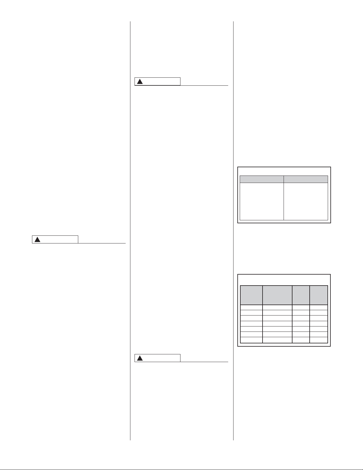
BAROMETRIC DRAFT
CONTROL
The barometric damper (see figure 9) is
a control installed in the flue pipe to
regulate the draft in the furnace. If the
draft increases in the chimney, the
damper opens to maintain the preset
draft in the furnace. Should the draft
decrease in the chimney, the damper
will close to maintain the preset draft of
the oil furnace. A barometric damper is
supplied with each furnace and must be
installed by the following the
instructions supplied by the
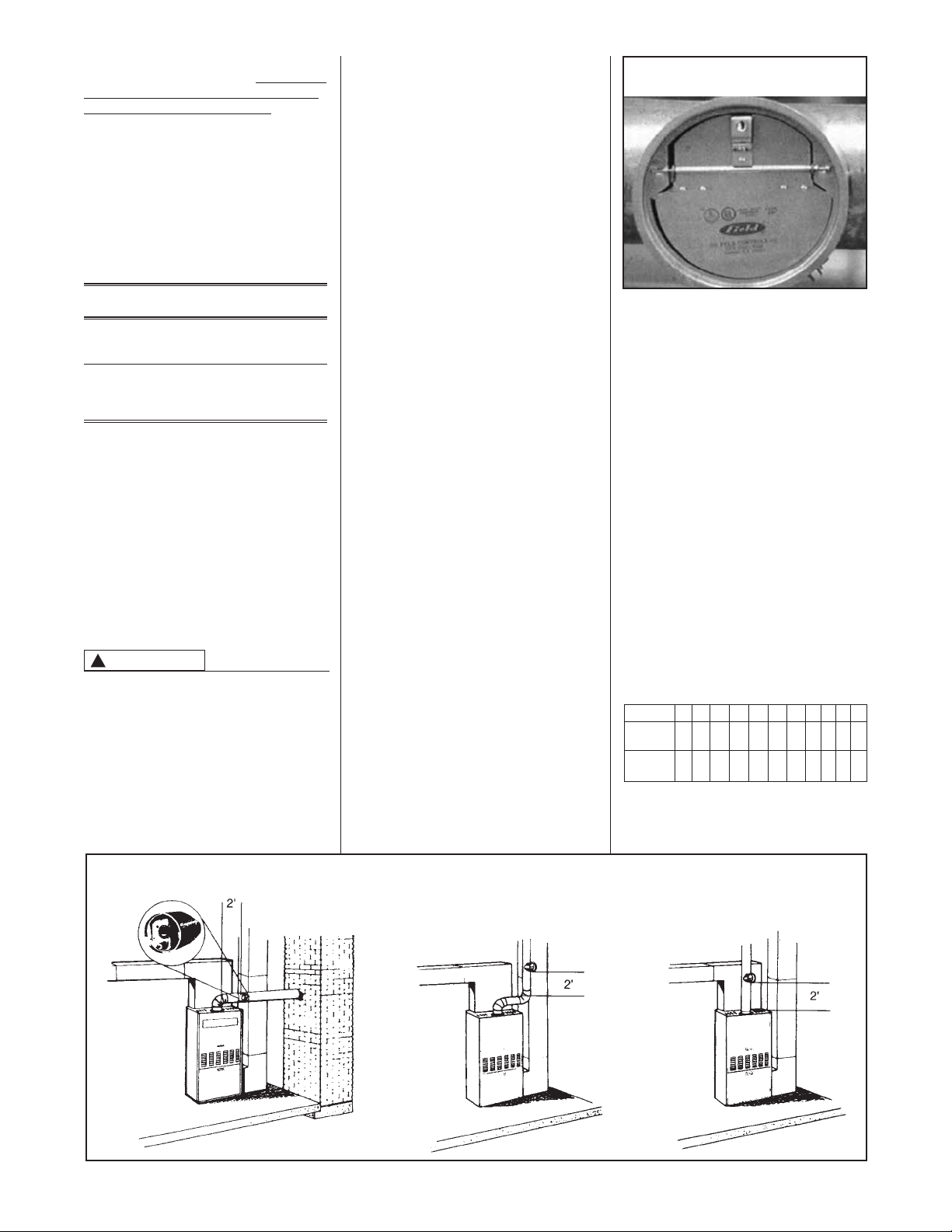
manufacturer. The barometric damper
control should be installed between the
flue outlet of the furnace and the
chimney (see figure 10). The
barometric damper control should be
set for proper draft on start up after the
furnace has been operating for 10 to 15
minutes. See Oil Burner Adjustment
Procedure Section for proper draft
settings.
On start up, the furnace must be set
for field conditions with a
combustion kit for proper operation.
NOTE: Always use a separate
barometric damper for each oil-fired
appliance. Install the barometric
damper with its hinge level and the face
plumb. Tilting causes erratic damper
operation. Installation of a barometric
damper must be in accordance with the
Installation and Operation Instructions
provided with the damper.
The following standards and codes will
help to make the installation. Current
editions of these standards can be
obtained from:
American National Standards Institute,
1430 Broadway, New York, NY 10018
Metal Thickness for
Galvanized Steel Pipe Connectors
Diameter of Galvanized Minimum
Connector Sheet Thickness
(in.) (mm) Gauge No. (in.) (mm)
< 6 < 152 26 0.019 0.48
≥ 6 to ≤ 10 ≥ 152 to ≤ 254 24 0.024 0.61
> 10 to ≤ 16 > 254 to ≤ 406 22 0.029 0.74
>16 > 406 16 0.056 1.42
FIGURE 10
RECOMMENDED BAROMETRIC DAMPER LOCATIONS
FIGURE 9
BAROMETRIC DAMPER
WARNING
!
Lift (in feet) 0 1 2 3 4 5 6 7 8 9 10
3/8" O.D.
53 40 45 41 38 33 20 25 21 18 13
Tubing
1/2" O.D.
100 100 100 100 100 100 100 99 83 68 52
Tubing
Recommended Maximum Length of Tubing
Used on a Single Stage (3450 RPM) Pump Two
Pipe System
Page 11

11
retain particles that are less than 50
microns (rated at 44 microns or 325
mesh, or less) in size to prevent
accumulation of small particles
(agglutination) at the nozzle slots and
remove these particles before they
reach these burner components.
Dual filtration, using a primary filter
(mounted near the supply tank) to
protect the secondary filter (usually
mounted just ahead of the burner)
should also be rated for particles less
than 50 microns in size. The purpose
of dual filtration is to prevent stacking,
or agglutinatioin, of particles less than
50 microns and may be necessary for
some applications.
Filtration, single or dual, will protect the
nozzle and prevent erratic or improper
spray patterns that reduce efficiency,
cause damage, higher maintenance
costs or the need for emergency
service.
Underground tanks or tanks below the
burner may require a two-pipe hookup. A check valve should be installed in
the suction line to keep the line primed
and the internal by-pass in the fuel unit
must be plugged as per instructions
furnished with the burner.
All oil lines must be tight and free of
traps. Lines should be buried or
otherwise protected from mechanical
injury. (See Typical Installation
Diagrams.)
ELECTRIC WIRING
TURN OFF ELECTRIC POWER AT
FUSE BOX OR SERVICE PANEL
BEFORE MAKING ANY ELECTRICAL
CONNECTIONS. FAILURE TO DO SO
CAN CAUSE ELECTRICAL SHOCK
RESULTING IN PERSONAL INJURY
OR DEATH.
CABINET MUST BE PERMANENTLY
GROUNDED. A GROUND SCREW IS
PROVIDED IN THE JUNCTION BOX
FOR THIS PURPOSE.
GROUND CONNECTION MUST BE
COMPLETED BEFORE MAKING ANY
LINE VOLTAGE CONNECTIONS.
TANK AND OIL LINES
Oil storage tank should be of an
approved type installed in accordance
with the National Board of Fire
Underwriters and local regulations.
In accordance with standards of the
National Board of Fire Underwriters,
inside tanks should be at least seven
feet from burner, convenient for
installing the fill, vent and feed lines.
The fill and vent lines should be run to
a convenient outdoor location and
should slope downward to tank. They
should terminate in approved fittings.
An approved type of oil gauge should
be installed in accordance with
manufacturer’s instructions. Copper
tubing no smaller than 3/8” O.D. is
recommended for suction or feed line
on basement tank installations. A hand
shut-off valve should be installed at the
tank outlet. An oil filter should be
installed in the suction or feed line.
IN A TWO-PIPE SYSTEM (ONE
SUPPLY AND ONE RETURN) DO
NOT
INSTALL A SHUTOFF VALVE
ON THE RETURN LINE. DOING SO
CAN CAUSE DAMAGE TO THE
EQUIPMENT, OR CAUSE A FIRE
RESULTING IN PROPERTY
DAMAGE, INJURY OR DEATH.
SINGLE AND DUAL OIL
FILTRATION
We recommend the use of a
replaceable core, or spin-on type,
supply line (suction) oil filter or dual
filtration (primary and secondary)
filters. As oil tanks age, sediment or
sludge, will accumulate. Without a
filter, suspended particles of moisture
and heavy oil that fall to the bottom of
the tank can make their way into the
fuel pump or nozzle. These particles
will stack and restrict flow at the nozzle
slots.
Filters can be disposable, or cleanable
construction (for number 2 fuel) sized
for the suction line, using flare fittings.
Do not use compression fittings.
Select the filter by GPH (gallon per
hour) flow-rate and pressure drop
through the filter after determining the
maximum flow rate, one-pipe or twopipe system, requirements. The filter
should be installed indoors and
serviced/replaced annually.
A pump strainer can filter particles at
150 microns, nozzles have filtration at
50 microns. The filter selected should
WARNING
!
WARNING
!
Lift (in feet) 0 2 4 6 8 10 12 14 16 18
3/8" O.D.
68 63 58 53 48 42 37 32 27 22
Tubing
1/2" O.D.
100 100 100 100 100 100 100 100 100 88
Tubing
Recommended Maximum Length of Tubing
Used on a Two Stage (3450 RPM) Pump Two
Pipe System
FAILURE TO GROUND APPLIANCE
COULD RESULT IN ELECTRICAL
SHOCK, FIRE, PROPERTY
DAMAGE, PERSONAL INJURY OR
DEATH.
Installation of the electric supply line
should be in accordance with the
National Electric Code ANSI/NFPA No.
70, latest edition, and local building
codes.
Use a separate fused branch electrical
circuit containing a properly sized fuse
or circuit breaker. Run this circuit
directly from the main switch box to an
electrical disconnect (switch) which
must be readily accessible and located
within sight of the furnace.
Connect from the disconnect to the
junction box on the furnace inside the
control compartment. Discard test
leads and connect the line voltage
wires in their place (see figures 31, 32
& 33).
NOTE: H (hot) and N (neutral) polarity
must be observed when making field
connections to the furnace. The limit
control will not interrupt H (hot) circuit if
leads are reversed.
THERMOSTAT
POWER ROBBING THERMOSTATS
IMPORTANT: There are three basic
types of thermostats. They are:
mechanical, battery powered and
power robbing. Thermostats that are
powered by furnace transformer
voltage, referred to as “power
robbing,” may not be used. Use of a
power robbing thermostat will result in
intermittent operation.
TABLE 6
LOW VOLTAGE WIRING
SOLID COPPER WIRE - AWG
3.0 16 14 12 10 10 10
2.5 16 14 12 12 10 10
2.0 18 16 14 12 12 10
50 100 150 200 250 300
LENGTH OF RUN - FEET
The total wire length is the distance from the furnace to the thermostat and back
to the furnace.
NOTE: Do not use 24 volt control wiring smaller than No. 18.
THERMOSTAT
LOAD - AMPS
WARNING
!
Page 12

12
TYPICAL INSTALLATION DIAGRAMS
FIGURE 11
TWO PIPE INSTALLATION
FIGURE 12
ONE PIPE INSTALLATION
Page 13

13
LIGHTING INSTRUCTIONS
This appliance is equipped with an
automatic electronic ignition device.
This device lights the oil burner each
time the room thermostat “closes” calls
for heat. See oil burner instructions
enclosed with furnace for further detail.
MAKE SURE THAT COMBUSTION
CHAMBER IS FREE OF OIL BEFORE
USING RESET BUTTON ON
PRIMARY CONTROL. FAILURE TO
DO SO CAN CAUSE FLASH FIRE OR
EXPLOSION RESULTING IN
PROPERTY DAMAGE, PERSONAL
INJURY OR DEATH.
TO START FURNACE
1. Set room thermostat to highest
setting.
2. Open shut-off valve in oil supply line.
3. Close line switch. Burner should
start automatically.
4. Bleed the fuel pump as soon as the
burner motor starts rotating. To
bleed the fuel unit, attach a clear
plastic hose over the bleed plug.
Loosen the plug and catch the oil in
an empty container. Tighten the plug
when all air is purged. (See section
titled “Oil Pump/Pump” for more
information on bleeding the pump.)
WARNING
!
5. Reset room thermostat to desired
temperature setting.
TO STOP FURNACE
1. Set the room thermostat to lowest
temperature setting.
2. Turn “Off” line switch to the furnace.
IF BURNER DOES NOT START
1. Check fuse or breaker in the furnace
circuit.
2. Assure room thermostat is set above
room temperature.
3. Check oil level in the tank.
4. Make sure that oil line shut-off
valves are open.
5. Wait five minutes to allow the control
to cool, so that it will recycle. Reset
the button on the primary control.
6. Depress manual reset button on the
motor.
NOTE: Do not expose cad cell to
direct electric bulb light or sunlight.
Light may enter through the air control
band slot and upset the electric circuit
of this device.
OPERATING INSTRUCTIONS
FIGURE 14
COMPONENT LOCATION
ST-A1066-01
NOTE: Do not use 24-volt control
wiring that is smaller than number 18
AWG. The maximum circuit ampacity
is 1.6. The Heat Anticipator should be
set for 0.10 amps.
NOTE: An isolation relay can be added
to prevent any compatibility problems
that may occur. Use a single-pole,
single-throw relay with 24-volt AC coil.
The contacts should be rated for .5
amps minimum at 24 volts. See Figure
13.
The current ProStock part number is
42-25104-01 for a SPNO Pilot/Power
24 volt relay.
IMPORTANT: Do not use a powerrobbing electronic thermostat with this
furnace. Use only mechanical
thermostats or battery powered
electronic thermostats.
Install the room thermostat in
accordance with the instruction sheet
packed in the box with the thermostat.
Run the thermostat lead wires inside
the blower compartment and connect
to low voltage terminals as shown on
the wiring diagram. Never install the
thermostat on an outside wall or where
it will be influenced by drafts,
concealed hot or cold water pipes or
ducts, lighting fixtures, radiation from
fireplace, sun rays, lamps, televisions,
radios or air streams from registers.
Refer to instructions packed with the
thermostat for “heater” selection or
adjustment.
NOTE: Do not use 24 volt control
wiring smaller than No. 18 AWG.
HEAT ANTICIPATOR
SETTING
The heating thermostat anticipator
should be set for a 0.10 amp draw.
FIGURE 13
ISOLATION RELAY
➁
➂➀➃
TO THERMOSTAT
“W” TERMINAL
TO THERMOSTAT
“R” TERMINAL
JUMPER
RWC
Page 14

14
FIGURE 15
FLUE SAMPLING LOCATIONS
OIL BURNER ADJUSTMENT
AFTER FURNACE INSTALLATION,
EACH OIL FURNACE MUST
BE
OPERATED IN THE HEATING
CYCLE AND PROPER BURNER
ADJUSTMENTS COMPLETED FOR
EACH FURNACE INSTALLATION
FIELD CONDITION. THIS IS
REQUIRED FOR EACH OIL
FURNACE INSTALLED. SEE
“BURNER ADJUSTMENT” PORTION
OF THE FURNACE INSTALLATION
AND OPERATING INSTRUCTION.
THE ADJUSTMENTS ARE
NECESSARY TO PREVENT SMOKE,
SOOT, ODOR FROM ENTERING THE
STRUCTURE AND SUBSEQUENT
FURNACE DAMAGE.
THE FOLLOWING ADJUSTMENTS
ARE NECESSARY TO PREVENT
SMOKE, SOOT, ODOR AND
POSSIBLE EQUIPMENT DAMAGE.
AN EXPERIENCED SERVICE
MECHANIC AND RELIABLE
INSTRUMENTS ARE REQUIRED.
The following procedure is based on
guidelines taken from
"The Professional Serviceman's Guide To Oil Heat
Savings"
by R.W.Beckett Corporation,
and is based on the U.S.
Environmental Protection Agency's
"Guidelines for Residential Oil Burner
Adjustments"
printed in 1975. Some
procedures have been changed to
meet the specific units being
addressed.
CAUTION
!
FURNACE ADJUSTMENT
PREPARATION STEPS
1. Calibrate and check the operation
of all measuring equipment. Follow
the manufacturer's recommended
procedures for calibration and
equipment check out. Calibration
instructions are included in the
operation instructions for the Fyrite
CO
2 Gas Analyzer. See Fyrite CO2
section in this manual.
2. Prepare the heating unit for
testing. Drill ONE 1/4 inch hole in
the flue between the heating plant
and the barometric damper, if not
already there as shown in Figure
14. If space permits, the hole
should be located in a straight
section of the flue, at least two flue
diameters from the elbow in the
flue pipe and at least one diameter
from the barometric damper.
Another 1/4 inch hole is provided
by the manufacturer for testing
over the fire.
Drill another 1/4” hole between the
barometric damper and the
chimney as shown in Figure 14.
The draft at this location must
measure at least -.05 to -.06
inches W.C. within three minutes
after the burner starts. Failure to
achieve this measurement
indicates chimney draft problems
which must be corrected for proper
operation. See Figure 24 for
chimney problem correction.
3. Make sure the burner air tube, fan
housing, and blower wheel are
clear of dirt and lint.
4. Nozzle inspection. Annual replacement of the nozzle is recommend-
ed. The nozzle size should match
the capacity of the unit installed.
Nozzle size is listed on the unit
nameplate. An in-line oil filter will
reduce service problems due to
nozzle clogging. It should be
located as close as possible to the
oil burner. Care should be taken to
prevent air leakage into the oil
suction line. Use continuous runs
of copper tubing and use a
minimum number of joints and
fittings. Always use flare fittings.
Refer to the nozzle specifications
for the correct nozzle and spray
pattern, whenever replacing the
nozzle.
5. Adjustment of electrodes. Adjust
the ignition electrodes according
to the burner manufacturer’s
instructions to assure prompt
ignition. See the electrode
adjustment section in this manual
for more information.
6. Operate the burner; adjust the air
setting for a proper flame by visual
observation (until no smoke is
present), and run for at least 10
minutes or until operation has
stabilized. If a proper flame is not
obtainable, reset the air band and
air shutter settings to the original
factory settings (see table 7).
7. Check pump pressure. Bleed air
from the pump and nozzle piping.
Check the pump pressure and
adjust to 100 psi, if necessary.
See the pump section in this
manual for more information.
Page 15

15
COMBUSTION ADJUSTMENT
THE FOLLOWING BURNER
ADJUSTMENTS MUST BE MADE
AFTER 10 TO 15 MINUTES OF
OPERATION.
8. Set the draft. Remove the heat
shield and then remove the metal
plug in the burner mounting plate.
Check the draft reading over the
fire with a draft gage through the
5/16" hole located in the burner
plate. See the draft gauge section
in this manual for more
information. Adjust the barometric
damper to give the overfire draft
recommended by the manufacturer.
If no such recommendations are
available, set the overfire draft to
assure a negative pressure within
the combustion chamber (usually a
negative 0.01 to 0.02 inches water
column).
Replace the hole plug in the
burner mounting plate after these
tests have been made.
9. Check the smoke readings. After
the burner has been operating 10
minutes, make a smoke measurement in the flue following the
smoke tester instructions. See the
smoke pump section in this
manual for more information. Oily
or yellow smoke spots on the filter
paper are usually a sign of unburned fuel, indicating very poor
combustion (and likely high emissions of carbon monoxide and
unburned hydrocarbons). This
condition can sometimes be
caused by too much air, or other
factors. If this condition cannot be
corrected, major correction or
even burner replacement may be
necessary. Adjust the air shutter
and air band for a 0 to a 1 smoke
number (a trace).
10. Check the CO
2
with the Fyrite
analyzer. See Fyrite Gas Analyzer
section for methods and
procedures. Adjust the air setting
to reduce the CO
2
reading by
between 1% and 2%. Lock the air
adjustment and repeat all draft,
CO
2
, and smoke measurements to
make sure the setting has not
shifted.
COMBUSTION DIAGNOSIS
11. Check performance. A wellmatched and well-tuned burner
should be capable of operation at
a CO
2
level between 10% and
12%.
checking cut off pressure. Slow
pump cutoff at the end of a firing
cycle can cause smoke and other
pollutant emissions. Check for
prompt pump cutoff by observing
the flame or by checking for
smoke at shutdown. If poor cutoff
is observed, make sure all air is
purged from the pump and nozzle
line. If poor cutoff continues check
for proper cutoff pressure.
15. Check Controls. Check the
settings of all operating controls
before leaving the installation and
verify that they are in working
order.
16. Check for proper temperature rise
of the supply air. See the air
supply temperature section in this
manual for details.
17. Annual Cleanup. An overall burner
checkup and cleanup is
recommended annually. See the
annual cleanup section in this
manual for more information.
FINAL CHECKS
12. Measure the flue temperature. See
the stack thermometer section in
this manual for more information.
Operating the unit at an excessive
firing rate generates more heat
than the heat exchanger can
utilize and results in unnecessary
heat loss up the chimney. Other
causes of excessive heat loss are
badly sooted heat-exchanger
surfaces and excessive draft. The
temperature of the flue gas
provides an indication of these
heat losses.
Measure the net flue temperature
by subtracting the room air temperature from the thermometer
reading. Excessive flue loss is
indicated if the net flue
temperature during steady
operation exceeds 600° F.
13. Check Ignition. Check the
operation over repeated cycles to
insure prompt ignition on starting.
14. Check pump cutoff (80 psi is cutoff pump pressure). See pump
section for the procedure for
Table 7
FACTORY AIR ADJUSTMENT SETTINGS
BURNER
AIR SHUTTER
SETTING
AIR BAND
SETTING
OIL FURNACE
MODEL
BECKETT
MODEL
AFG
AFG
AFG
AF42JYPWHS
AF42XNPWHS
AF42JZPWHS
10
10
7
BLANK
2
4
-067
-112
-150
BECKETT
DESIGNATION
Page 16

adjustment screw (see Figure 16)
counterclockwise until the pump cuts
out. This will be to confirm the pump cutout pressure. The pump should stop at
about 80 psi. Once this is confirmed, turn
the pump pressure adjustment screw
clockwise a couple of turns and re-apply
a heat call to start the pump and furnace
running again.
Continue to adjust the pump until the
mid temperature rise has been reached
and at least 100 psi. is reached. Do not
adjust the pump pressure to over 150
psi.
OIL PUMP/ PUMP
BLEEDING
Before furnace operation can begin, the
fuel line and pump must be bled of air.
To do this, run a clear piece of hose with
a special bleed tool attached from the
bleed port on the pump to a bucket or
can (see Figure 23). First, open the
bleed port by turning it counterclockwise.
Next, turn on the furnace by applying a
heat call or 24 AC volts to the “W”
terminal on the burner. The pump will
begin to force the fuel oil and air through
the clear tube. When no more air can be
seen in the tube, turn off the valve by
turning it clockwise. Finally, turn off or
remove the heat call or 24 AC volts from
the “W” terminal.
An assembly with a key to open the
bleed port can be constructed like that
shown in Figure 16.
CHECKING THE PUMP PRESSURE
The new Beckett burner assembly now
includes a Clean-Cut shutoff pump. This
pump will prevent oil from dripping into
the heat exchanger after the pump has
stopped. This is an improvement from
the older designs. However, this now
means that the new pump no longer has
a spare port from which oil pressure can
be easily taken.
To check the oil pressure on the new
Clean-Cut pumps, an assembly of tube,
pipe fittings and a pressure gage will
need to be constructed as shown in
Figure 17. The figure shows a list of
components necessary to create the
assembly. Other assemblies can be
made, as this is not the only assembly
that will work. This assembly can be
used to check the pressure on other OPF and -OBF oil furnaces so that only
one assembly is necessary for a toolbox
used in the field. Construct the assembly
as shown in Figure 17 and install it as
shown in Figure 18.
Once the pressure testing assembly has
been made and installed as shown in
Figure 18, turn on the furnace by
applying a heat call or applying 24 AC
Volts to the “W” terminal on the
thermostat input terminal block. After the
burner starts and flame has been
established, turn the pump pressure
Once the pump pressure has been
properly adjusted, remove the pump
pressure reading assembly and replace
the fittings and tubes to their original
configurations. Next, repeat the bleeding
procedure as above to insure that no air
remains in the oil supply line.
PUMP SELECTION
For all -OBF and -OPF oil furnaces that
use the R7184 primary control, a CleanCut pump with solenoid must be used.
Use of a standard pump without the
necessary solenoid will prevent
operation of the furnace. For this reason,
pumps from -OPC, -OPD, -OBC and OBD oil furnaces cannot be
interchanged with or used on the -OBF
or -OPF models.
For long pipe runs and installations
where the oil tank is below the burner, a
separate two-stage pump is available
from the parts replacement division. Be
sure to purchase a two-stage pump with
Clean-Cut solenoid. Use of a pump
without a Clean-Cut solenoid will prevent
furnace operation.
For information on when to use a twostage pump, consult the section titled
“OIL BURNER / PRIMARY CONTROL”
of this document.
FIGURE 17
EXAMPLE OF OIL PRESSURE TESTING ASSEMBLY.
16
General Service Pressure Gage 0-200 psi
Range with 1/4” NPT Male Connection
Brass Threaded Pipe Adapter Fitting –
1/4” NPT Male to 1/8” NPT Female
Brass Threaded Pipe Fitting – Tee with
1/8” NPT Female Thread
Compression Tube Fittings – Male
Straight Adapter (Self Aligning)
3/16” OD Tubing to 1/8” NPT Pipe
3/16” Copper Tubing with Standard
3/16” Compresion Tube Fittings on
Both Ends Approx. 4” Long.
FIGURE 18
OIL PRESSURE TESTING ASSEMBLY INSTALLED
FIGURE 16
BLEEDING THE PUMP
Pump Pressure Adjustment
Pump Bleed Access Port
Bleed Tool with Hose
Attached
Oil Pressure Testing Assembly from
Figure 17.
Install Oil Pressure Testing Assembly
to Existing Tube as Shown.
One Fitting to Mount to Burner
Existing Tubing Provided on Burner
Page 17

17
3. If the electrode position is correct,
the tips should be positioned where
the identifying marks on the gauge
intersect. These two lines
determine:
a. Correct tip spacing above the
nozzle.
b. Correct tip spacing ahead of
the nozzle.
The actual distance between
electrodes must be correct within
+/- 1/32".
4. If the electrode position is not
correct, the electrodes must be
readjusted and rechecked.
NOZZLE POSITION
1. Insert the nozzle line/electrode
assembly into the air tube (see
figure 21).
2. Place the wide section of the
gauge against the burner head
face with 1-1/8" wide end of the
gauge inserted into head.
3. Slide the nozzle line/electrode assembly forward until the nozzle
touches the gauge.
4. Secure the adjustable plate on the
burner housing side by tightening
the screw. Then tighten the nut,
securing the nozzle line where it
passes through the side of the
housing. This locks the assembly
into position.
The T500 nozzle, electrode and head
position gauge (see figure 19) is used
to correctly position the electrodes,
nozzle, and head. The gauge is the
best way to ensure that these adjustments are correct. This gauge is used
on the Beckett model "AFG" burners.
ELECTRODE POSITION
1. With nozzle line/electrode assembly out of the burner, place the
1-1/8" wide gauge edge against
the face of the nozzle and between
the electrode tips (see figure 20).
2. Position the gauge so the center
scribe mark is in line with the
nozzle orifice. (Do not scratch the
nozzle face)
The nozzle should now be located
properly with 1-1/8" set back from
the face of the burner head.
NOZZLE CONCENTRICITY
For proper burner operation the nozzle
must be concentric with the burner
head opening.
1. With the gauge inserted into the
head (see figure 21), the nozzle
orifice should be approximately in
line with the center scribe mark on
the 1-1/8" wide edge of the gauge.
The maximum eccentricity
allowable is identified by the two
outer scribe marks (+/- 1/16").
2. Rotate the gauge to assure
concentricity in a side-to-side as
well as up-down position.
If the nozzle is not concentric
within allowable limits, it generally
indicates either improper
construction or damaged parts. Do
not use. Replace with a correct assembly.
AIR VOLUME
ADJUSTMENTS
The amount of air delivered by the
blower is affected by the resistance of
the ductwork and registers. The factory
adjustment of the blower speed has
been made to suit the average
installation, designed and installed
according to the manuals published by
the National Warm Air Heating and Air
Conditioning Association. The speed of
the direct drive blower can be changed
by rewiring motor leads as described in
the wiring diagrams.
ELECTRODE ADJUSTMENT
FIGURE 19
T500
FIGURE 20
ELECTRODE ADJUSTMENT
FIGURE 21
NOZZLE DEPTH AND CONCENTRICITY
Page 18

18
SUPPLY AIR
TEMPERATURE
The temperature rise of the air through
a furnace will vary with each furnace.
For proper temperature rise of the
furnace in question, check the rating
plate on the furnace (see figure 2) or
Table 8 in this manual.
A. Temperature rise is the
temperature difference between
the air entering and leaving the
furnace.
B. The proper way to measure the
temperature rise follows: First
open all registers and dampers to
allow proper air flow. Then allow
the furnace to operate 10 to 15
minutes before taking the
readings.
C. Use two thermometers; insert one
in the supply air duct and one in
the return air duct. Do not place a
thermometer in the supply duct
directly above the heat exchanger
as the thermometer will pick up
radiant heat from the heat exchanger (see figure 22).
D. Calculate by subtracting the return
air temperature from the supply air
temperature.
EXAMPLE:
Supply air
temperature 155 degrees
Return air
temperature
75 degrees
Temperature
rise = 80 degrees
E. Compare the calculated tempera-
ture rise with the specified
temperature rise on the rating
plate.
TEMPERATURE RISE
TOO HIGH
• Check for proper fan speed
• Check static pressure on duct
system for proper air flow.
• Check proper cooling coil size.
• Check duct static pressures for
proper air flow.
• Check for proper oil pressure.
• Check nozzle size for overfiring.
• Check for a clean air filter.
• Check duct sizes to assure
adequate size for desired air flow.
The blower speed can be increased to
deliver more air over the heat
exchanger if the duct system is large
enough to allow the increase. If the
duct system is not of adequate size increasing fan speed may result in less
air flow than originally found.
TEMPERATURE RISE
TOO LOW
• Check for proper fan speed.
• Check nozzle size to make sure it
is of proper size.
• Check for excessive soot in the
heat exchanger. Low system
efficiency may indicate a sooted
heat exchanger.
The motor speed can be changed to a
lower speed to decrease the air flow
over the heat exchanger.
FIGURE 22
DETERMINING TEMPERATURE RISE
Page 19

19
TRUE-SPOT
True-Spot smoke tester (see figure 23)
by Bacharach is used to check smoke
levels in flue products.
INSTRUCTIONS FOR USE:
1. Tear a sample strip of filter paper
along the perforation line; loosen
the clamp screw, insert the filter
paper strip in the slot and tighten
the clamp screw.
2. Insert the sampling tube into the
flue through a 1/4" diameter hole
between the draft regulator and
the furnace flue outlet (see
figure 24).
TABLE 8
6. To take additional samples clamp
the filter paper strip in the slot so
that the previous spot is visible.
SMOKE SCALE READINGS:
1. Excellent - Little, if any, sooting.
2. Good - May be slight sooting, with
little, if any, increase in flue gas
temperature.
3. Fair - Substantial sooting, but
rarely will require cleaning more
than once a year.
4. Poor - This is a borderline smoke
- some units may soot only moderately, others may soot rapidly.
5 Very Poor - Heavy sooting in all
cases - may require cleaning
several times during a heating
season.
6 Extremely Poor - Severe and
rapid sooting - may result in damage to the stack control and
reduce the overfire draft
dangerously.
TIPS FOR BETTER SMOKE
READINGS
1. Before using, tap the sampling
tube to loosen any soot or rust,
tighten the clamp screw without
any filter paper in the slot and
purge with several rapid pump
strokes of room air.
2. Warm the True-Spot to room
temperature before using.
3. In sampling, be sure to pull the
pump handle through 10 full
strokes and hold for several
seconds at the end of each pull
stroke. Use a steady pull motion
such that a full stroke is obtained
in 3 or 4 seconds.
4. Hold the smoke scale with the
filter paper at arm’s length when
comparing the spot with the chart.
5. Take several readings.
6. Keep the Smoke Scale clean and
store in an envelope provided
when not in use.
FAN/LIMIT CONTROL
The high limit cut-off switch is factory
set to meet safety requirements. This
setting is not adjustable.
The fan is cycled by a solid state fan
timer control located in the blower
cavity (see figure 14).
3. Pull the True Spot handle through
10 full pump strokes.
4. Remove the filter paper strip from
slot (see figure 25).
5. Match the smoke spot on the filter
paper to the closest color shade on
the Bacharach oil burner smoke
scale RR 776 (see figure 26).
FIGURE 23
TRUE-SPOT
FIGURE 24
SMOKE SAMPLE
FIGURE 25
SMOKE SPOT
FIGURE 26
SMOKE SCALE
MODEL
NUMBER
-067
-0112
-150
— (.50, .65) -70°B 40 - 70
(1.0) -70°B (.75, .85) -70°B 50 - 60
(1.2, 1.35) -70°B — 60 - 90
DELAVAN
NOZZLE
SIZES
DEL-O-FLO
NOZZLE
SIZES
TEMPERATURE RISE
RANGE*
(DEGREES F)
*Recommended temperature rise is the midpoint of the given range.
Page 20

20
BURNER
For proper operation, replace the
burner oil nozzle each year with the
factory recommended size and type. It
is located in the burner drawer. (See
instructions furnished with burner for
details.)
Periodically clean ignition electrodes,
blower wheel and all filters in the oil
line. Service should be performed by a
qualified service technician at least
once yearly at the beginning of the
heating season.
LUBRICATION
IMPORTANT: DO NOT attempt to
lubricate the bearings on the blower
motor. Addition of lubricants can
reduce the motor life and void the
warranty.
The blower motor is permanently
lubricated by the manufacturer and
does not require further attention.
The blower motor must be cleaned
periodically by a qualified installer,
service agency, or the oil supplier to
prevent the possibility of overheating
due to an accumulation of dust and dirt
on the windings or on the motor
exterior.
AIR FILTER
Filter application and placement are
critical to airflow, which may affect the
heating and cooling system
performance. Reduced airflow can
shorten the life of the systems major
components, such as motor, limits,
elements, heat exchanger, evaporator
coil or compressor. Consequently, we
recommend that the return air duct
system have only one filter location.
The most common location will be
inside the furnace or air handler or a
filter base. For systems with a return
air filter grill or multiple filter grills, can
have a filter installed at each of the
return air openings. DO NOT DOUBLE
FILTER THE RETURN AIR DUCT
SYSTEM. DO NOT FILTER THE
SUPPLY AIR DUCT SYSTEM.
If high efficiency filters or electronic air
cleaners are used in the system, it is
important that the airflow is not
reduced to maximize system
performance and life. Always verify that
the systems airflow is not impaired by
the filtering system that has been
installed, by performing a temperature
rise and temperature drop test.
The air filters must be kept clean. Dirty
filters can restrict airflow. The motor
depends upon sufficient air flowing
across and through it to keep from
overheating.
In a new house, the air filter may
become clogged within a short time
due to the presence of dust in the air
and air ducts. A dirty filter retards the
flow of air and prevents proper airflow.
Permanent filters should be cleaned
and disposable filters should be
replaced at least once a year and more
often if necessary (see User’s Info.
Manual).
NOTE: Do not use high static return
air filters to replace standard furnace
filters.
MAINTENANCE
ACCESSORIES
RXOP-D25 PARALLEL
FURNACE KIT
For twinning two upflow oil furnaces.
PLENUM DATA
Plenum adapters are required in some
instances for use on upflow applications
when plenum and furnace size do not
match.
SS1-R SIDEWALL VENT
SYSTEM
This furnace is agency approved by UL,
ULC for use with the Tjernlund SS1-R
Sidewall Vent System (date code of
012204 or later) when installed in
accordance with the installation
instructions provided by Tjernlund.
Common venting with another appliance
is NOT an option when using the
Tjernlund SS1-R. The use of any other
type of power vent system is not
approved or recommended by the
manufacturer.
TWO-STAGE PUMP
For applications requiring extra lifts, twostage fuel pumps are available from
PROSTOCK™ as part number.
FOSSIL FUEL KITS
RXPF-F01—Use for standard heat pump
applications.
RXPF-F02—Use for TVA (Tennessee
Valley Authority) applications.
FURNACE PLENUM PLENUM COIL
WIDTH WIDTH ADAPTER PLENUM
(IN.) [mm] (IN.) [mm] UPFLOW
21 [533] 21 [533] — RXBC-A21
24
1
⁄2 [622] 241⁄4 [616] — RXBC-A24
28 [711] 24
1
⁄2 [622] RXBA-AD RXBC-A24
Page 21

21
CAUSE
1. Roof peak or other surrounding
objects higher than chimney top.
2. Flue cap on chimney.
3. Coping smaller than chimney
interior.
4. Air leak from loose bricks or
mortar.
5. Inside dimensions of chimney are
too small.
6. Double chimney separation wall
leaks due to loose bricks or
mortar.
7. Joist protruding into chimney.
8. Brick, mortar or other obstruction
lodged in chimney.
9. Soot accumulation in offset.
10. Offset is too short.
11. More than one heating appliance
connected to same chimney flue.
12. Smoke pipe protrudes into chimney
or elbow too far.
13. Smoke pipe is loose fitting, too
long or has too many elbows.
14. Opening between chimney flues.
15. Loose fitting cleanout door.
16. New chimney.
17. Excessive draft..
CORRECTION
Extend chimney 24 inches above roof
and surrounding objects within 30 feet.
Remove.
Enlarge to match chimney interior.
Replace loose bricks and mortar.
If all other causes have been
eliminated a new chimney may have
to be built.
Replace loose bricks or mortar.
Remove.
Have chimney cleaned.
Clean out.
Straighten or lengthen offset.
Furnace ideally should have its own
flue. If this is not possible, smoke pipe
should be connected as shown in
Figure 29.
Make flush with inside of chimney.
Cement joints, shorten and eliminate
elbows.
Seal openings permanently.
Seal openings, close door tightly.
Allow 2 to 4 weeks to dry.
Open barometric damper.
CORRECTION OF POOR CHIMNEY DRAFT CONDITIONS
FIGURE 30
If it is necessary to connect more
than one heating appliance to
the same chimney, connect
furnace flue pipe as “B.” Connect
lower BTU appliance pipe as “A.”
FIGURE 28
Pipe pushed too far inside elbow, as
shown, interferes with draft.
FIGURE 29
If chimney ends only a short
distance below point where flue
enters, make a “toothpick joint”
as shown. Remove soot from
below regularly.
FIGURE 27
CHIMNEY PROBLEMS
Page 22

22
FIGURE 31
BECKETT MODEL “AFG” BURNER
OIL BURNER DATA
TABLE 9
DRAWER ASSEMBLY DATA
UNIT SIZE
NOZZLE*
G.P.H./ANGLE/PATTERN
END
CONE
STATIC DISC RATING
-067
-112
-150
*NOTE: This appliance should only be used with specified Delavan or Del-O-Flo nozzles. Use of other nozzles may result
in unsatisfactory performance.
DEL-O-FLO (.50, .65) -70°B
DELAVAN (1.0) -70°B
DEL-O-FLO (.75, .85) -70°B
DELAVAN (1.2, 1.35) -70°B
F0
F3
F6
3-3/8” SOLID
2-3/4” SOLID
3-3/8” SOLID
AF**JY
AF**XN
AF**JZ
BECKETT MODEL “AFG” BURNER
Page 23

23
TROUBLESHOOTING
Important: 90% of start-up
problems are due to air leaks in
the suction line.
COMPLAINT
Odor, soot and smoky fire
Delayed ignition
Burner will not operate
Burner motor runs but does not fire
Pulsations
CHECK FOR:
1. Insufficient combustion air
2. Lack of proper draft
3. Cracked/plugged heat exchanger
4. Burner not adjusted properly with combustion kit
5. Improper setting of barometric draft control
6. Oil leaks
7. Wrong nozzle size, or nozzle worn or partially clogged
8. Improper setting of electrodes
9. Plugged oil filter
10. Fuel pump cutoff valve not cutting off
11. Nozzle or electrodes improperly positioned
12. Leakage on return side of air distribution system
13. After drip, reflected heat, or impingement of flame
14. Improper or distorted end cone
15. Air leakage into oil pump supply line
16. Burner blower air inlet restricted or burner blower wheel dirty
17. Restricted flue
1. Cracked, dirty or loose electrodes
2. Electrodes not properly adjusted
3. Incorrect nozzle
4. Improper primary air adjustment
5. Faulty ignition transformer
6. Water in fuel oil
7. Incorrect pump pressure
8. Furnace not properly set-up
9. Air leakage into oil supply line
1. Open switch
2. Open fuse or circuit breaker
3. Burner motor overload open
4. Thermostat improperly set
5. Burner primary control safety open
1. Oil supply insufficient
2. Faulty oil pump
3. Broken oil pump drive coupling
4. Coke deposits on electrodes
5. Air in oil supply line
6. Restricted oil supply line
7. Clogged nozzle
8. Restricted oil line filter
9. Leak in oil line
10. Failed ignition transformer
11. Electrodes not properly set
12. Dirty fire detector
1. Improper nozzle
2. Inadequate draft
3. Air in oil line
4. Clogged flue
5. Furnace not properly set-up
6. Partially clogged pump strainer or oil line filter
7. Nozzle plugged
8. Nozzle too far forward in air tube
9. Barometric damper set wide open
Page 24

24
COMPLAINT
Cad cell not functioning
Low CO
2
High stack temperatures
High smoke reading
Burner motor runs but does not fire
Poor draft - overfire and stack
Noisy Operation
CHECK FOR:
1. Requires direct view of flame
2. External light effecting cell operation
3. Remove cad cell and check with an ohmmeter:
a. With cad cell covered, the resistance should be over 100K ohms
b. With cad cell exposed to room light, the resistance should be
under 1.5 K ohms
1. High draft through furnace
2. Improper primary air adjustment
3. Damaged combustion chamber
4. Faulty nozzle
5. Incorrect oil pressure
6. Draft regulator improperly set
7. Incorrect fuel/air mixture
1. Damaged combustion chamber
2. Furnace not set-up with combustion kit
3. Undersized return air
4. Overfired furnace
5. Dirty heat exchanger
6. High draft, barometric damper not properly set
7. Excessive temperature rise
8. Air shutter adjustment open too much.
1. Lack of combustion air
2. Inadequate overfire draft
3. Incorrect oil pressure
4. Dirty burner blower wheel
5. Incorrect nozzle
6. Faulty oil pump
7. Dirty oil
8. Burner motor not obtaining full speed
9. Damaged combustion chamber
10. Flame impingement
11. Incorrect fuel/air mixture
1. Improperly sized chimney or not enough chimney height
2. Holes or cracks in chimney
3. Restricted chimney
4. Too many 90 degree elbows in vent pipe
5. Outside chimney too cool
6. Cool flue gases
7. Barometric damper not properly set, sticking or in wrong location
8. Oil furnace and fireplace chimney interconnected
9. Heat exchanger passages plugged
10. Overfired furnace
11. Improper air shutter adjustment
1. Bad coupling alignment
2. Air in oil supply line (use only good flare fittings)
3. Tank hum on two-pipe system and inside tank
Page 25

25
Oil Pump Pressure Problems And
Their Possible Causes
COMPLAINT
Excessive Pressure
Insufficient Pressure
Fluctuating Pressure
No Pressure
CHECK FOR:
1. Bypass plug in place with a single oil line system
2. Return oil line on two-pipe system clogged, kinked or restricted
3. Pressure regulating valve stuck
4. Oil too heavy
5. Improper pump setting
1. Nozzle size beyond rated pump pressure
2. Pump vapor bound due to high oil line vacuum
3. Nozzle badly worn
4. Pump gears worn
5. Suction line kinked, clogged or restricted
6. Pressure regulating valve worn or stuck in operating position
7. Dirty strainers
8. Dirty line filter
9. Motor does not come up to speed
10. Bad air leak at seal
11. Improper pump setting
1. Pump gears worn
2. Vertical oil lift too great (over 10 feet)
3. Pump strainer or oil line filter partially clogged
4. Bypass plug not in place with two line system
5. Pump vapor bound due to high vacuum
6. Faulty foot or check valve
7. Suction line too small
8. Sticky pressure regulating valve
9. Motor coupling grabbing
1. Pump air bound
2. Loose coupling
3. Oil tank empty
4. Strainer or filter completely clogged
5. Suction line completely restricted
6. Air leaks in suction line
7. Gears badly worn and pump cannot create vacuum to lift oil
8. Badly leaking pump or filter seal
9. Wrong pump rotation
10. Tank vent clogged
Page 26

26
FIGURE 32
TROUBLESHOOTING
(see page 22 for more extensive troubleshooting solutions)
BURNER SEQUENCE OF OPERATION
CHECK MAIN POWER, PRESS PRIMARY CONTROL RESET.
CHECK LOW VOLTAGE WIRING/CONTROLS
CHECK FOR FALSE LIGHT ON CAD CELL
CHECK FUEL SUPPLY, OIL LINES, OIL LINE VALVES, TRIAL
CHECK OIL NOZZLE,
CHECK PRIMARY CONTROL / CAD CELL,
CHECK IGNITION TRANSFORMER / ELECTRODES
CHECK ELECTRODES, IGNITION TRANSFORMER,
CHECK FUEL SUPPLY, NOZZLE
CHECK CAD CELL / PRIMARY CONTROL
CHECK FAN CENTER
CHECK BLOWER MOTOR WIRING
CHECK BLOWER MOTOR CAPACITOR
CHECK THERMOSTAT AND CONTROL WIRING.
CHECK ISOLATION RELAY
CHECK PRIMARY CONTROL
CHECK PRIMARY CONTROL
CHECK FAN CENTER AND WIRING
T’STAT CALLS FOR HEAT
IGNITOR / MOTOR START
BURNER STARTS 15 SEC
FOR IGNITION
FLAME ESTABLISHED,
MOTOR & IGNITOR
CONTINUE
MAIN BLOWER STARTS
THERMOSTAT OPENS,
HEAT CALL ENDS
IGNITOR AND MOTOR
STOP / BURNER OFF
MAIN BLOWER OFF
YES
NO
YES
YES
YES
YES
YES
YES
NO
NO
NO
NO
NO
NO
Page 27

27
FURNACE ADJUSTMENT CHECK SHEET
Customer’s Name Date:
Address
Furnace Model #
Serial #
Nozzle Size/Angle/spray pattern gal./hr.
/
°
/ pattern
Electrodes Adjusted
Nozzle Oil Pressure PSIG
Overfire Draft inches negative H
2O
Breech Draft inches negative H
2O
Chimney Draft inches negative H
2O
Smoke Reading
%CO
2
%CO2
Stack Temperature degrees F.
Room Temperature degrees F.
Net Stack Temperature degrees F.
Burner Efficiency
Supply Air Temperature degrees F.
Return Air Temperature degrees F.
Supply Air Temperature Rise degrees F.
Air Band / Air Shutter settings
Installer’s signature
Page 28

28
FIGURE 33
HEATING AND COOLING SCHEMATIC 38
FOR MODELS WITH UTEC 1012-925 INTEGRATED FURNACE CONTROL
IMPORTANT: Do not use a power-robbing thermostat with this furnace. Use only mechanical thermostats or
battery powered thermostats.
Page 29

29
FIGURE 34
HEATING AND COOLING CONTINUOUS LOW SPEED BLOWER SCHEMATIC
IMPORTANT: Do not use a power-robbing thermostat with this furnace. Use only mechanical thermostats or
battery powered thermostats.
Page 30

30
NOTES
Page 31

31
NOTES
Page 32

32 CM 1005
NOTES
 Loading...