

Page 1
WARNING: Plumber – Be Aware
Use copper pipe ONLY. Plastic pipe MUST NOT be used.
It is a requirement of a solar water heater installation that all
pipe work be in copper and not plastic, due to the effects of
high water temperatures and pressures.
Installation Instructions
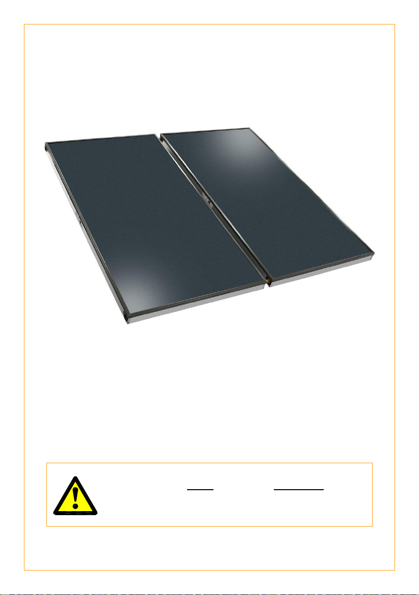
Solar Collector Kit
Solar Collector Add On Kit
NPT 200 SOLAR COLLECTORS
This collector kit must be installed and serviced by a qualified person
Please leave this guide with the householder.
Page 2
WARNING: Plumber – Be Aware
The solar hot and solar cold pipes between the solar storage tank and the
solar collectors MUST BE of copper. All compression fittings must use
brass or copper olives.
The full length of the solar hot and solar cold pipes MUST BE insulated.
The insulation must:
be of a closed cell type or equivalent, suitable for a solar water heating
application and capable of withstanding the temperature of the water
generated by the solar collectors under stagnation conditions
The specification of the chosen insulation material should be checked
with the insulation manufacturer prior to installation as different
materials may vary in temperature tolerance.
be at least 13 mm thick, however thicker insulation may be required to
comply with the requirements of either AS/NZS 3500.4 or
AS/NZS 3500.5:2012 Section 3 (for a Class 1a or Class 10 building) as
applicable under the Plumbing Code of Australia
be weatherproof and UV resistant if exposed
extend through any penetrations in the eaves, ceiling and roof
cover valves and fittings in the solar pipe work
be fitted up to and cover the connections on both the solar storage tank
and the solar collectors.
Note: Failure to observe these requirements also increases the risk
of freeze damage.
Uninsulated pipe work, including concealed in cavities and roof spaces or
where it may be in contact with a metal roof, may lead to freeze damage.
The system has NO WARRANTY for freeze damage if the solar hot and
solar cold pipes are not insulated in accordance with the installation
instructions.
The insulation is essential to assist in providing freeze protection, will offer
protection to a metal roof against corrosion due to water running off the
copper pipes, assist in avoiding accidental contact with the solar pipe work
as very high temperature water can flow from the solar collectors to the
solar storage tank, and also reduce pipe heat losses.
Plumber: It is important to refer to and read in full the complete
“Warning: Plumber – Be Aware” statement commencing on page 13.
2
Page 3

CONTENTS
HOUSEHOLDER - This installation instruction booklet is
intended for the installer but you may find it of interest.
Notice to Victorian Customers from the
Victorian Plumbing Industry Commission.
This water heater must be installed by a licensed person
as required by the Victorian Building Act 1993.
Only a licensed person will give you a Compliance Certificate, showing that
the work complies with all the relevant Standards. Only a licensed person will
have insurance protecting their workmanship for 6 years. Make sure you use
a licensed person to install this water heater and ask for your Compliance
Certificate.
Components And Kit Contents .................................................. 4
System Installation ...................................................................... 5
Installation – Solar Storage Tank ............................................... 7
Installation – Solar Collectors .................................................... 8
Roof Assembly Of Solar Collectors ......................................... 17
Connection Details .................................................................... 25
Pipe Work Roughing In Dimensions ........................................ 29
Installation – Solar Collectors .................................................. 31
Warranty Note ............................................................................ 35
3
Page 4
SOLAR COLLECTOR KIT AND COLLECTOR ADD ON KIT
For installation with a solar storage tank.
Your solar water heater is designed for the solar collectors to be roof mounted
and the solar storage tank to be installed at ground or floor level. The collector
kits are suitable for:
Collector Kit (1 or 2 solar collectors)
299139 NPT 200 solar collectors Screwed fittings
Collector Add On Kit (for each additional solar collector)
299140 NPT 200 solar collector Screwed fittings
Note: One Collector Add On Kit is required for each additional solar collector.
Part No
Kit Components and Description
299139
Collector
kit
NPT 200
299140
Add on kit
NPT 200
129870
Installation instructions roof kit
1
-
191614
Collector angle 1 panel
-
1
191613
Collector angle 2 panel
1
-
191801
Collector straps
4
3
080022
Screws self tapper ½” x 8G ZP pan head
8
3
330695
Collector union assembly
2
2
063603
Connector M33
1
-
063604
Sensor connector M33 assembly – consisting of:
1 x 063605 fitting M33-15BSP for temp sensor
1 x 088062 sensor nipple solar loline
1 x 087026 O ring 5/16” ID x 1/16 BS011 silicone
1
-
088027
Compression olive copper ½”
2
-
080055
Compression nut brass ½”
2
-
063602
End plug collector M33
2
-
330606
Blanking disc
2
-
330171
O ring 25 ID x 3.2
8
4
056001
or
056029
Hot sensor assembly Loline
1
-
087025
O ring 5/32” ID x 1/16
2
-
123204
Label hot pipe / cold pipe
1
-
348071
Cable ties 150 mm long
3
-
COMPONENTS AND KIT CONTENTS
4
Page 5

SYSTEM INSTALLATION
THIS WATER HEATER IS NOT SUITABLE FOR POOL HEATING.
The system is suitable for installation with NPT 200 solar collectors as part of an
open circuit system installation.
The system is not suitable for installation above 400 metres altitude.
IMPORTANT NOTES
Working on roofs is and should always be considered a hazardous activity,
particularly early in the morning, late in the evening, when the roof is wet and
during and after periods of rain.
All work must be carried out in accordance with Local, State and Federal
Occupational Safety, Health and Welfare Regulations. In particular, the
requirements for safety whilst manual lifting, working at heights and on roofs.
Installers must be competently trained in:
Height Hazard Assessment
Working at Height Procedures
Assessment / Use / Wearing of correct height safety equipment
(harnesses etc.)
All other relevant safety factors specific to the installation and
maintenance work to be compliant with suitable Occupational, Health and
Safety Regulations / Codes.
All relevant permits shall be obtained from the regulatory authorities before
commencing work to install the solar hot water system.
All work carried out must be performed by appropriately qualified
tradespeople or be suitably supervised for trades assistant duties.
Every care must be taken to protect and warn occupants of the building and
the public from personal injury which may occur from falling tools, roof
materials, fittings or any other hazards of a general nature.
Advise the occupants of any inconvenience which may occur due to
disconnection of existing water and electrical supplies.
The connection, attachment, integration or general association of other
equipment or parts which either directly or indirectly affect the operation or
performance of this equipment could void the warranty.
5
Page 6

SYSTEM INSTALLATION
INSTALLATION STANDARDS
The water heater must be installed:
by a qualified person, and
in accordance with the installation instructions, and
in compliance with Standards AS/NZS 3500.4 or AS/NZS 3500.5:2012
Section 3 (for a Class 1a or Class 10 building) as applicable under the
Plumbing Code of Australia, AS/NZS 3000 and all local codes and regulatory
authority requirements.
In New Zealand, the installation must also conform to Clause G12 of the New
Zealand Building Code.
WATER HEATER APPLICATION
This water heater is designed for use in a single family domestic dwelling for the
purpose of heating potable water. Its use in an application other than this may
shorten its life.
If this water heater is to be used where an uninterrupted hot water supply is
necessary for the application or business, then there should be back-up
redundancy within the hot water system design. This should ensure the continuity
of hot water supply in the event that this water heater was to become inoperable
for any reason. We recommend you provide advice to the system owner about
their needs and building back-up redundancy into the hot water supply system.
OPEN CIRCUIT SYSTEM INSTALLATION
An open circuit system has a collector circuit which is directly connected to the
potable water in the solar storage tank. Potable water from the solar storage tank
circulates through and collects heat gained by the solar collectors and then
circulates back into the solar storage tank.
Freeze Protection
The system has a level of freeze protection designed to guard the system against
damage from freeze conditions. The system must be installed with the full length
of the solar hot and solar cold pipes insulated to offer protection against freeze
damage (refer to “Warning: Plumber Be Aware” on page 13). Freeze conditions
occur below 6°C.
The system has NO WARRANTY for freeze damage when installed above
400 metres altitude or if the solar hot and solar cold pipes are not insulated in
accordance with the installation instructions (refer to “Warranty Note” on
page 35).
Note: Warranty against freeze damage applies only to systems installed in
Australia.
6
Page 7

INSTALLATION – SOLAR STORAGE TANK
SOLAR WATER HEATER STORAGE TANK LOCATION
The solar storage tank should be installed close to the most frequently used
outlet and its position chosen with safety and service in mind.
Consideration must also be given to the position of the solar storage tank in
relation to the solar collectors. There are limitations on the maximum length of
the solar hot and solar cold pipes between the solar storage tank and the solar
collectors. Refer to “Solar Collector Location” on page 8, to “Pipe Lengths” on
page 12 and to “Maximum Height to Collectors” on page 15.
Refer to the installation instructions supplied with the solar storage tank for
installation details of the solar storage tank.
7
Page 8

INSTALLATION – SOLAR COLLECTORS
SOLAR COLLECTOR LOCATION
Consideration must be given to the position of the solar collectors in relation to
the solar storage tank. There are limitations on both the maximum length of the
solar hot and solar cold pipes and the maximum height between the solar storage
tank and the solar collectors. Refer to “Solar Collector Location” on page 8, to
“Pipe Lengths” on page 12 and to “Maximum Height to Collectors” on page 15.
The solar collectors must be installed in a shade free position. The surrounds
should be checked for higher buildings or trees which may cause shade at other
times of the year and for small trees which may grow and shade the solar
collectors in the future.
The installation must comply with the requirements of either AS/NZS 3500.4 or
AS/NZS 3500.5:2012 Section 3 (for a Class 1a or Class 10 building) as
applicable under the Plumbing Code of Australia, and all local codes and
regulatory authority requirements.
Refer to the installation instructions supplied with the solar storage tank for
details on the installation of the solar storage tank.
ROOF STRENGTH
The installer must ensure the structural integrity of the building is not
compromised by the solar water heater installation and the roof structure is
suitable to carry the full weight of the solar collectors and frame (if one is
installed). If in any doubt of the construction or the condition of the roof, the roof
should be suitably strengthened. Consult a structural engineer. Each solar
collector and its fittings weighs approximately 42 kg when full of water.
ROOF AREA FOR INSTALLATION
Roof area required for solar collectors:
4 solar collectors – 4.6 m wide x 2.0 m deep. Weight (full) 168 kg approx.
3 solar collectors – 3.5 m wide x 2.0 m deep. Weight (full) 126 kg approx.
2 solar collectors – 2.4 m wide x 2.0 m deep. Weight (full) 84 kg approx.
1 solar collector – 1.3 m wide x 2.0 m deep. Weight (full) 42 kg approx.
In addition to this area, a minimum of one (1) metre clearance is recommended
to be left around the solar collectors on all four sides for safe service access.
8
Page 9

INSTALLATION – SOLAR COLLECTORS
Maximum Number of Collectors
The maximum recommended number of these non-selective collectors for each
tank size as part of an open circuit system is:
410 model tank – 4 x NPT200 collectors
325 model tank – 3 x NPT200 collectors
270 model tank – 3 x NPT200 collectors
ORIENTATION OF SOLAR COLLECTORS
To help maximise system performance, solar collectors should be installed with
an optimum orientation facing true north (in the southern hemisphere) or true
south (in the northern hemisphere). Always check for true north or true south
using a compass or other suitable device.
The solar performance of a system reduces as the orientation of the collectors
moves away from the optimum orientation, resulting in the need for increased
boosting to supply the same hot water load. Solar collectors facing up to 45° from
the optimum orientation will receive about 4% to 5% less total solar radiation.
However, the optimum orientation of solar collectors is not always practical or
achievable. Solar collectors may be installed up to 90° from the optimum
orientation. Where the orientation is greater than 60° from the optimum, it may
be possible for an additional solar collector to be installed or to install selective
surface collectors in lieu of non-selective surface collectors to help make up for
the reduction in solar performance compared to the optimum orientation. Each
option should be discussed with the system owner.
If neither of these options are possible nor acceptable to the system owner, then
the system owner needs to be made aware of, understand and accept that
increased boosting may be required to meet their hot water requirements.
9
Page 10

INSTALLATION – SOLAR COLLECTORS
INCLINATION OF SOLAR COLLECTORS
To help maximise system performance, solar collectors should be installed with
an optimum inclination. This is equal to 90% to 100% of the local latitude angle
when collectors are oriented within 60° of true north or true south, and between
10° and 20° when the collectors are oriented between 60° and 90° from the
optimum orientation.
Generally, improved summer performance is obtained from an angle of
inclination less than the optimum angle and improved winter performance is
obtained by an angle of inclination greater than the optimum angle. If the angle
of inclination varies by 20° from the optimum angle, the solar collectors will
receive about 10% less total annual solar radiation. The latitude of some
Australian cities are listed on page 11.
However, the optimum inclination of solar collectors is not always practical or
achievable. Solar collectors may be installed at the roof angle for simplicity of
installation and appearance, but must never be flat for a pumped solar open
circuit water heater installation. Although the solar collectors can be installed with
an inclination of less than 10°, this is not advised. The risks include:
the collector glass not 'self-cleaning', leading to dirty collector glass reducing
solar performance, and
condensation on the underside of the glass taking longer to clear, and
condensation droplets falling onto the absorber plate potentially causing
discolouration.
The collector kit is suitable for installations with an inclination of up to 30°. Where
the solar collectors are installed at inclinations greater than 30°, a With Pitch
frame is necessary. Refer to your local Solar Distributor for details.
A Variable Pitch frame can be installed to increase the angle of inclination of the
collectors used in a solar pumped water heater installation. This type of frame
should be used if the roof pitch either varies by more than 20° from the optimum
angle or is less than 10°.
The use of a Variable Pitch frame should be discussed with the system owner. If
this option is neither possible nor acceptable to the system owner, it may be
possible for an additional solar collector to be installed or to install selective
surface collectors in lieu of non-selective surface collectors to help make up for
the reduction in solar performance compared to the optimum inclination. Each
option should be discussed with the system owner.
If these options are neither possible nor acceptable to the system owner, then
the system owner needs to be made aware of, understand and accept that
increased boosting may be required to meet their hot water requirements.
10
Page 11

INSTALLATION – SOLAR COLLECTORS
Adelaide
35°S
Cairns
17°S
Hobart
42°S
Port Hedland
20°S
Alice Springs
24°S
Canberra
35°S
Mildura
34°S
Rockhampton
24°S
Brisbane
27°S
Darwin
12°S
Melbourne
38°S
Sydney
34°S
Broken Hill
31°S
Geraldton
28°S
Perth
32°S
Townsville
19°S
CYCLONIC OR HIGH WIND AREAS
For an installation of solar collectors on a pitched roof in a cyclonic or high wind
area, a suitable With Pitch frame is required. Refer to your local Solar Distributor
for details.
The installation of these solar collectors on a suitable frame, subject to the
frame’s design criteria not being exceeded:
may be suitable for installation in geographic locations up to and within Wind
Region D (With Pitch frame) or up to and within Wind Region C (Variable
Pitch frame), as defined in the Building Code of Australia, Australian
Standard AS 4055 and the Australian / New Zealand Standard
AS/NZS 1170.2, or equivalent locations, and
may provide an acceptable method of installation where it is necessary to
satisfy the requirements of the Building Code of Australia for high wind
areas, or equivalent requirements.
LATITUDE OF SOME AUSTRALIAN CITIES
11
Page 12

INSTALLATION – SOLAR COLLECTORS
Maximum recommended total combined pipe length (solar hot + solar cold)
and number of 90° bends
Pipe Size
1 or 2 Collectors
3 Collectors
4 Collectors
Pipe Length
90°
Bends
Pipe Length
90°
Bends
Pipe Length
90°
Bends
DN15
40 metres
20
30 metres
20
15 metres
20
DN20
NR
NR
40 metres
20
40 metres
20
For each additional 90° bend, reduce the maximum total pipe length by 0.5 metres.
For each additional metre of pipe length, reduce the number of 90° bends by two.
Note: One 90° elbow is equal to two 90° bends. NR – not recommended.
PIPE LENGTHS
The solar hot and solar cold pipes between the solar storage tank and the solar
collectors shall:
be of bendable grade or hard drawn copper tube.
Annealed or soft copper shall not to be used.
have a continuous fall from the solar collectors to the solar storage tank.
Horizontal runs of pipe work are acceptable and may be installed as part of
an open circuit system.
Care must be taken to ensure the pipe work maintains a continuous fall or
horizontal runs over the life of the installation. Pipe work should be fixed at
regular intervals to assist in maintaining this requirement.
not exceed the maximum recommended combined lengths as specified in
the table.
Notes:
It is important to connect the solar hot and solar cold pipes to the correct
connections at the solar collectors and at the solar storage tank.
The solar cold pipe connects to the bottom of the solar collector array and
may connect to either the left or right hand side. The solar hot pipe must
connect to the top of the solar collector array diagonally opposite to the solar
cold pipe connection. The solar hot outlet connection is to be the highest
point of the system.
The hot sensor connection is at the solar hot outlet where the solar hot pipe
connects to the solar collector for this open circuit system.
Refer to “Warning: Plumber – Be Aware” on page 13.
It is essential for these requirements to be followed for the system to operate
correctly and efficiently. Solar pipe work which is oversized, or is too long, or
does not have a continuous fall can result in a reduction in performance or the
system not operating effectively.
12
Page 13

INSTALLATION – SOLAR COLLECTORS
WARNING: Plumber – Be Aware
The solar hot and solar cold pipes between the solar storage tank and the
solar collectors MUST BE of copper. All compression fittings must use
brass or copper olives.
The full length of the solar hot and solar cold pipes MUST BE insulated.
The insulation must:
be of a closed cell type or equivalent, suitable for a solar water heating
application and capable of withstanding temperatures of up to 150°C,
which may be generated by the solar collectors under stagnation
conditions
The specification of the chosen insulation material should be checked
with the insulation manufacturer prior to installation as different
materials may vary in temperature tolerance.
be at least 13 mm thick, however thicker insulation may be required to
comply with the requirements of either AS/NZS 3500.4 or
AS/NZS 3500.5:2012 Section 3 (for a Class 1a or Class 10 building) as
applicable under the Plumbing Code of Australia
be weatherproof and UV resistant if exposed
extend through any penetrations in the eaves, ceiling and roof
cover valves and fittings in the solar pipe work
be fitted up to and cover the connections on both the solar storage tank
and the solar collectors.
Note: Failure to observe these requirements also increases the risk
of freeze damage.
Uninsulated pipe work, including concealed in cavities and roof spaces or
where it may be in contact with a metal roof, may lead to freeze damage.
The system has NO WARRANTY for freeze damage if the solar hot and
solar cold pipes are not insulated in accordance with the installation
instructions.
The insulation is essential to assist in providing freeze protection, will offer
protection to a metal roof against corrosion due to water running off the
copper pipes, assist in avoiding accidental contact with the solar pipe work
as very high temperature water can flow from the solar collectors to the
solar storage tank, and also reduce pipe heat losses.
13
Page 14

INSTALLATION – SOLAR COLLECTORS
WARNING: Plumber – Be Aware
The insulated copper pipe work:
should be fixed at suitable locations to prevent or reduce the possibility
of noise from water hammer and vibration from occurring
is not to be placed or installed in contact with plastic pipe work.
Likewise, plastic pipe work is not to be placed or installed in contact
with the insulated copper pipe work after the collector circuit is installed.
The solar hot outlet and hot sensor connection is to be the highest point of
the system. The highest point of the solar hot and solar cold pipes must be
where they connect to the solar collectors, to avoid the possibility of air
locks occurring in the system. There MUST BE a continuous fall in the
pipe work from the solar collectors to the solar storage tank. Horizontal
runs of pipe work are acceptable and may be installed as part of an open
circuit system.
Plastic pipe MUST NOT be used, as it will not withstand the temperature
and pressure of the water generated by the solar collectors under
stagnation conditions. Extremely high water temperatures up to 150°C for
non-selective surface collectors and greater than 200°C for selective
surface collectors and extremely high water pressures can be generated
under these conditions. Plastic pipe cannot withstand these temperatures
and pressures and MUST NOT be used. Failure of plastic pipe can lead to
the release of high temperature water and cause severe water damage
and flooding.
The pressure applied to the collector circuit and solar collectors during a
pressure test of an open circuit system MUST NOT exceed 1000 kPa
where NPT200 solar collectors are installed, otherwise damage may
result.
Refer to “Pressure Testing” on page 16.
Upon completion of the installation of the NPT200 solar collectors the
packaging material may be removed, whether or not the collector circuit is
connected to the solar storage tank and / or the solar water heater is
commissioned.
14
Page 15

INSTALLATION – SOLAR COLLECTORS
Maximum Height to Collectors
The maximum height of a pumped open circuit solar installation, from the solar
controller (circulator) to the top of the solar collectors, is determined by the
maximum recommended total pipe length for the system and the water supply
pressure.
The maximum recommended total pipe length of the collector circuit should not
be exceeded and a minimum water supply pressure of 200 kPa should be
available at the inlet to the system, otherwise the system performance may be
reduced or the collector circuit may not be purged of air during the commissioning
of the system.
Open Circuit System
Pipe Work Installation Requirements
15
Page 16

INSTALLATION – SOLAR COLLECTORS
Pressure Testing
The solar water heater, including the collector circuit, is to be isolated during the
testing and commissioning of the heated water reticulation system in a building
in accordance with Clause 9.3 (a) of AS/NZS 3500.4:2015 or Clause 3.34.2 (a)
of AS/NZS 3500.5:2012 for a Class 1a or Class 10 building as applicable under
the Plumbing Code of Australia. The collector circuit includes the solar hot and
solar cold pipes and solar collectors.
It may be necessary to pressure test the collector circuit to comply with codes
and regulatory authority requirements or on other occasions where the solar
collectors and solar hot and solar cold pipes are installed prior to the solar
storage tank, such as on a building site.
Collector Circuit
Warning: The pressure applied to the collector circuit during a pressure test
of an open circuit system MUST NOT exceed 1000 kPa where NPT200 solar
collectors are installed, otherwise damage may result to the solar collectors.
Open Circuit System
If the solar collectors, solar pipe work and solar storage tank are installed and
commissioned together, then the flooding of the collector circuit with water under
mains pressure for an open circuit system and checking the pipe work for leaks
during the commissioning procedure can be substituted for the pressure testing
of the collector circuit.
16
Page 17

ROOF ASSEMBLY OF SOLAR COLLECTORS
Notes:
These solar collectors have passed the AS/NZS 2712 requirements for
resistance to hailstone damage, so it is not normally necessary to fit a guard
to a collector. Stone Guards are available to provide a level of protection to
the collectors against vandalism or accidental damage. Refer to your local
Solar Distributor for details.
Warranty DOES NOT cover breakage of solar collector glass. Check your
insurance policy covers collector glass breakage.
Warning: No attempt should be made to remove or replace broken
collector glass.
The collector glass is not offered as a replacement part. Should the solar
collector require replacement, contact your local Solar Distributor for details.
Warning: Do not remove the solar collector packaging completely, prior
to the installation as the solar collector surface can become very hot. Remove
only sufficient packaging material to enable the installation of the solar
collectors.
Upon completion of the installation of the NPT200 solar collectors, such as
on a building site, the packaging material may be removed whether or not the
collector circuit is connected to the solar storage tank and / or the solar water
heater is commissioned.
The solar collector packaging must be removed completely prior to the
permanent operation of the water heater.
All connectors, end plugs, ‘O’ rings, brass fittings, collector straps and
collector angle required for the installation are included with the collector kit.
Suitable screws or anchors will be required to fix the collector straps to the
rafters for a pitched roof installation.
Screws to secure the collector straps and collector angle to the solar
collectors must not be longer than 15 mm. Suitable screws are provided in
the collector kit.
All olive compression fittings must use brass or copper olives.
Use an approved thread sealant such as Teflon tape on all other threaded
joints. Fittings with an O-ring do not require a thread sealant.
Roof Condition: Check the condition of the roof and advise the client of any
broken tiles or damaged roof sheeting before commencing the installation.
17
Page 18

ROOF ASSEMBLY OF SOLAR COLLECTORS
Numbers in parentheses refer to items in the diagrams on pages 31 (two solar
collector installation) and 32 (three or four solar collector installation).
DO NOT MODIFY THESE PARTS IN ANY WAY.
1. Solar Frame: If a solar frame is to be installed, determine the location of the
frame(s). Refer to “Solar Collector Location” on page 8 and the installation
instructions provided with the frame(s).
Assemble and fix the frame(s) to the roof in accordance with the installation
instructions provided with the frame.
Depending upon the positioning of the frame on the roof and any minor fall
the roof may have, ensure the collector rail is either horizontal or is higher
on the hot outlet side of the solar collectors. If in doubt use a spirit level.
Proceed to step 4.
2. Solar Collector Location: If a solar frame is not installed, select a suitable
position for the solar collectors.
Refer to “Solar Collector Location” on page 8.
3. Collector Angle – Pitched Roof Installation: Determine the location of the
collector angle(s) (1). If more than two solar collectors (17) are installed,
locate the collector angle(s) (1) from the Collector Add On kit(s) adjacent to
the first collector angle (1).
Hook two collector straps (2) to each bottom collector angle (1).
When positioned, the collector angle is to be either horizontal or have a rise
across the solar collectors from the solar cold connection side up to the solar
hot connection side for an open circuit system. The solar hot outlet and hot
sensor connection is to be the highest point of the system.
Note: Refer also to “Tile Roof with a flat tile profile” on page 18 if the
installation is on a tile roof where the tile has a flat profile. Additional
requirements for the positioning of the collector rail and installation of the
solar collectors apply.
Tile Roof with a flat tile profile: If the installation is on a tile roof with a flat
tile profile, the solar collectors (17) must be installed at an angle from the
horizontal to assist in rainwater runoff. The solar hot outlet side must be on
the left hand side and the solar cold inlet must be on the right hand side of
the collector array.
The top end of the solar collector on the solar cold inlet side must sit atop
the lower end of a tile lap. Measure down the roof approximately 1940 mm
from this point to determine the position of the bottom collector rail.
18
Page 19

Horizontal
Horizontal
Solar Hot
Outlet
Position top
of collector
as low as
practical
on roof tile
Solar Hot
Outlet
Horizontal
Position top
of collector
as low as
practical
on roof tile
FOLDED TRAY COLLECTORS
EXTRUDED RAIL
ENVELOPE COLLECTORS
EXTRUDED RAIL
30-40mm
from
horizontal
15-20mm
from horizontal
30-40mm
from
horizontal
Solar Cold Inlet
15-20mm
from horizontal
Solar Cold Inlet
15-20mm
from horizontal
Solar Cold Inlet
30-40mm
from
horizontal
Position top
of collector
as low as
practical
on roof tile
ROOF ASSEMBLY OF SOLAR COLLECTORS
Ensure the end of the collector angle (1) at the outlet side (left hand side) of
the solar collectors is higher up the roof than the end of the collector angle
at the inlet side (right hand side) of the solar collectors by:
15 – 20 mm for one solar collector, or
30 – 40 mm for two solar collectors, or
45 – 60 mm for three solar collectors.
This is to provide a downward angle along the top end of the collectors to
assist in rainwater runoff in order to prevent pooling.
Flat Tile Profile – Collector Angle From Horizontal
Failure to adhere to this requirement may result in pooling of rainwater at
the top of the collectors. If the top end of the collector array is too close to
the lap of the tiles, there is a risk of pooling water seeping up and under the
tile lap. The rainwater runoff is to flow from left to right to reduce the risk of
water working through the joints between tiles.
Tile Roof: Remove the tiles on the next row above the position of the
collector angle (1) to expose the rafters. Position the collector angle (1) and
fix the collector straps (2) directly to the rafters, using suitable screws or
anchors. Replace the tiles.
Metal Roof: Once the collector angle (1) is in position, fix the collector
straps (2) to the rafters, through the metal roofing material, using suitable
screws or anchors. Care should be taken not to mark Colorbond or other
metal roof sheet with a marking pen and to remove all swarf from the metal
roof as these can cause deterioration of the metal roofing material.
19
Page 20

ROOF ASSEMBLY OF SOLAR COLLECTORS
Note: Fixings must penetrate only through the high point in the roof material
profile. AS/NZS 3500.4 states a minimum of three (3) screws 40 mm long
be used per fixing strap. Longer screws or anchors may be required to
achieve a 40 mm minimum embedment into rafters for a metal roof.
Additional screws or anchors may be required.
4. Solar Collectors: Using a lifting device, lift the first solar collector (17) onto
the roof and place it carefully with the lower end seated in the collector
angel (1) and prior to positioning the next solar collector, screw the collector
angle (1) to the solar collector (17) using one of the screws (13) provided.
Repeat this procedure for additional collectors (17), screwing the collector
angle (1) to the solar collector (17) using one of the screws (13) provided.
Solar Frame Installation: Using a lifting device, lift the first solar collector (17)
onto the roof and place it carefully with the lower end seated in the collector
rail (1) and prior to positioning the next solar collector, firmly clamp (two
clamps per collector) to the collector rail using the clamps, hex screws,
washers and nuts provided.
Repeat this procedure for additional collectors (17), firmly clamping each
collector to the collector rail (1) with two clamps (13) prior to positioning a
subsequent collector.
Note: Screwing or firmly clamping each solar collector to the collector rail
as it is placed in position reduces the possibly of the collector(s) accidently
moving or sliding off the collector rail.
Remove the red transit plugs from the collector sockets.
5. Collector Unions: Couple the solar collectors (17) together using the
collector unions (3) and ‘O’ rings (6) supplied in the collector kit.
Refer to “Coupling Collector to Collector – Screwed Fittings” on page 25.
Note: It will be necessary to remove the screw or loosen the clamps on a
collector prior to it being coupled to its adjacent collector. Secure the screw
or the clamps again on each collector after it is coupled to the adjacent
collector.
6. Fixing Collector (bottom): Ensure the solar collectors (17) are correctly
positioned, centred and well seated in the collector angle (1).
Pitched Roof Installation: Screw the collector angle (1) to the solar
collectors (17) (two screws per collector), using the screws (13) provided.
Solar Frame Installation: Tighten the clamps (13) on each solar
collector (17).
20
Page 21

ROOF ASSEMBLY OF SOLAR COLLECTORS
7. Collector Strap (top) – Pitched Roof Installation: Position a collector
strap (2) against the top end of each solar collector (17).
Tile Roof: Remove the tiles on the next row above the top edge of the solar
collectors (17) to expose the rafters. Once in position, fix the collector
straps (2) directly to the rafters, using suitable screws or anchors. Replace
the tiles.
Metal Roof: Once in position, fix the collector straps (2) to the rafters,
through the metal roofing material, using suitable screws or anchors. The
collector straps (2) may be cut to a length of approximately 100 mm to retain
the aesthetics of the installation.
Note: Fixings must penetrate only through the high point in the roof material
profile. AS/NZS 3500.4 states a minimum of three (3) screws 40 mm long
be used per fixing strap. Longer screws or anchors may be required to
achieve a 40 mm minimum embedment into rafters for a metal roof.
Additional screws or anchors may be required.
Screw the collector straps (2) to the solar collectors (17) using the
screws (13) provided.
Solar Frame Installation: Ensure the solar collectors are correctly
positioned, centred and well seated in the top collector rail. Clamp the solar
collectors (two clamps per collector) to the collector rail, using the clamps,
hex screws, washers and nuts provided with the frame.
8. Connector: Fit a connector (10) to the inlet of the solar collector array using
an ‘O’ ring (6) provided.
Refer to “Coupling Cold and Hot Pipes to Collector – Screwed Fittings” on
page 27.
9. Sensor Connector: Fit the sensor connector (4) (with hot sensor port) to
the outlet of the solar collector array using an ‘O’ ring (6) provided.
Note: If the installation is on a tiled roof, the orientation of the hot sensor
port and hot sensor probe (when installed) must be angled between the
perpendicular (90°) to the roof to a maximum 30° off perpendicular down the
roof. Refer to Detail E on page 28.
Refer to “Coupling Cold and Hot Pipes to Collector – Screwed Fittings” on
page 27.
10. End Plugs: Fit the end plugs (5) to the two remaining solar collector
connections using the ‘O’ rings (6) and blanking discs (7) provided.
Refer to “End Plug Assembly – Screwed Fittings” on page 26.
21
Page 22

ROOF ASSEMBLY OF SOLAR COLLECTORS
11. Solar Hot and Solar Cold Pipes: Install the solar cold pipe from the solar
storage tank to the solar collectors (17) and the solar hot pipe from the solar
collectors (17) to the solar storage tank.
The solar hot and solar cold pipes should be a minimum DN15, but sized to
suit the installation for an open circuit system. Refer to “Pipe Lengths” on
page 12.
The solar hot and solar cold pipes must have a continuous fall from the solar
collectors to the solar storage tank. Horizontal runs of pipe work are
acceptable and may be installed for an open circuit system.
The full length of the solar hot and solar cold pipes must be insulated. The
insulation must be capable of withstanding the temperatures generated by
the solar collectors under stagnation conditions.
Warning: Plumber – Be Aware: It is important you refer to “Warning:
Plumber – Be Aware” on page 13 for important information relating to the
installation of the solar hot and solar cold pipes.
Refer also to installation diagrams on pages 31 and 32 and to “Pipe Work
Roughing In Dimensions” on page 29.
Notes:
Penetrations through the roofing material must be:
■ at the high point of the roof tile or metal sheet;
■ made neatly and kept as small as practicable;
■ waterproofed upon installation of the solar hot and solar cold pipes.
Exposed insulated pipe work between the solar collectors and the
penetration through the roofing material should be kept to a minimum to
maintain the aesthetics of the installation.
12. Connecting the Solar Hot and Solar Cold Pipes to Collectors: Connect
the solar cold pipe to the connector (10) at the inlet of the solar
collectors (17) and the solar hot pipe to the sensor connector (4) at the outlet
of the solar collectors (17) using the compression nuts and olives provided.
Refer to “Coupling Cold and Hot Pipes to Collector – Screwed Fittings” on
page 27 and the installation diagrams on pages 31 and 32.
22
Page 23

ROOF ASSEMBLY OF SOLAR COLLECTORS
13. Hot Sensor Lead – Collector Connection: Insert the sensor probe of the
hot sensor lead assembly (9) into the sensor connector (4), ensuring the
‘O’ ring is in position on the probe. Lock it into position with the locking
washer and clip provided.
Hot Sensor Lead – Solar Storage Tank Connection: Run the hot sensor
lead down to the solar storage tank. An extension sensor lead is available if
the hot sensor lead is not long enough to reach the solar control unit.
Connect the hot sensor lead to the hot sensor cable connecting socket
located at the underside of the solar control unit screwed to the side of the
solar storage tank.
14. Cable Ties: Secure the hot sensor lead at appropriate locations with the
cable ties (14) provided.
Notes:
The hot sensor lead may be cable tied to the outside of the insulation
on the solar pipe work.
Ensure the hot sensor lead is not in direct contact with the solar pipe
work at any point of the collector circuit, otherwise damage to the
sensor lead can occur due to the high temperatures which can be
experienced within the pipe work.
Damage to the hot sensor lead can result in solar gain not being
achieved and the freeze protection system being rendered inoperative.
15. Labels: At ground or floor level, adjacent to the location of the solar storage
tank, attach the ‘Solar Cold Pipe’ label (16) to the insulation on the solar cold
pipe to the solar collectors and the ‘Solar Hot Pipe’ label (15) to the
insulation on the solar hot pipe from the solar collectors.
Ensure the arrows on the labels are pointing in the correct direction of water
flow.
16. Pressure Testing the Collector Circuit: Upon completion of the solar
collector and solar hot and solar cold pipe installation, it may be required to
pressure test the collector circuit. Refer to “Pressure Testing” on page 16.
17. Connecting the Solar Hot and Solar Cold Pipes to the Solar Storage
Tank: Refer to “Connections – Plumbing” and “Installation – Solar Control
Unit” in the Owner’s Guide and Installation Instructions supplied with the
solar storage tank for details on the solar hot and solar cold pipe connections
to the solar storage tank.
18. Commissioning: Upon completion of the installation, refer to the Owners
Guide and Installation instructions supplied with the solar storage tank for
the commissioning procedure of the solar water heater.
23
Page 24

ROOF ASSEMBLY OF SOLAR COLLECTORS
INSTALLATION CHECK LIST
Once the installation is complete, it is important to check the following:
Maximum recommended total combined solar hot and solar cold pipe length
is not exceeded.
Solar hot and solar cold pipes are insulated in accordance with the
installation instructions.
The solar hot and solar cold pipes have a continuous fall from the solar
collectors to the solar storage tank. Horizontal runs of pipe work are
acceptable.
Ensure the collector angle is either horizontal or is higher on the hot outlet
side of the solar collectors. If in doubt use a spirit level.
Or if the installation is on a tile roof with a flat profile tile, then the end of the
collector angle at the outlet side (left hand side) of the solar collectors is
higher up the roof than the end of the collector angle at the inlet side (right
hand side) of the solar collectors by:
15 – 20 mm for one solar collector, or
30 – 40 mm for two solar collectors, or
45 – 60 mm for three solar collectors.
24
Page 25

CONNECTION DETAILS
P/No: 33-0171
O-Ring 25mm ID x 3.2 Thk
Solar Collector Solar Collector
P/No: 33-0171
O-Ring 25mm ID x 3.2 Thk
P/No: 33-0695
Collector Union
Solar Collector
COUPLING COLLECTOR TO COLLECTOR – SCREWED FITTING
Refer to installation diagrams on pages 31 and 32 for position and Detail A on
page 25.
1. Seat an ‘O’ ring (6) into each of the collector connections to be joined.
2. Fit a collector union (3) to each collector connection of the first solar
collector (17) to receive the second solar collector and screw in the unions
until they seat firmly against their ‘O’ ring (6). Hand tighten only so the solar
collectors can be shifted and centred.
3. Place the collector unions (3) into the collector connections on the second
solar collector and screw in the unions until they seat firmly against their
‘O’ ring (6). Hand tighten only so the solar collectors can be shifted and
centred.
4. Repeat steps 1 and 2 for a third and fourth solar collector (if installed).
5. After the solar collectors are centred on the collector rail(s), tighten each
collector union (3) with a spanner applying medium pressure.
DETAIL A – COLLECTOR UNION ASSEMBLY – SCREWED FITTING
25
Page 26

CONNECTION DETAILS
P/No: 33-0606
Blanking Disc
P/No: 33-0171
O-Ring 25mm ID x 3.2 Thk
P/No: 063602
Collector M33 End Plug
Solar Collector
END PLUG ASSEMBLY – SCREWED FITTING
Refer to installation diagram on page 31 for position and Detail B on page 26.
1. Seat an ‘O’ ring (6) into the collector connection.
2. Place a blanking disc (7) over the seated ‘O’ ring (6).
3. Place the end plug (5) into the collector connection and screw in until it seats
firmly against the blanking disc (7), applying medium pressure with a
spanner to tighten.
DETAIL B – END PLUG ASSEMBLY – SCREWED FITTING
26
Page 27

CONNECTION DETAILS
Solar Collector
Solar Collector Solar Collector
O-Ring 25mm ID x 3.2 Thk
Connector M33 - NPT
P/No: 063603
Copper Compression
Olive 1/2"
P/No: 088027
Brass Compression
Nut 1/2" x 15
P/No: 080055
P/No: 33-0171
O-Ring 25mm ID x 3.2 Thk
COUPLING COLD AND HOT PIPES TO COLLECTOR – SCREWED FITTING
Refer to installation diagram on page 31 for position and Detail C on page 27,
Detail D on page 28 and Detail E on page 28.
1. Seat an ‘O’ ring (6) into the collector connection.
2. Place the connector (10) into the collector connection and screw in the union
until it seats firmly against the ‘O’ ring (6), applying medium pressure with a
spanner to tighten.
3. Place the compression nut (11) and olive (12) over the end of the solar cold
pipe. Position the cold pipe into the connector (10), seat the olive (12) and
tighten the compression nut (11).
4. Repeat this procedure with the sensor connector (4) to couple the solar hot
pipe to the solar collector (17).
Note: If the installation is on a tiled roof, the orientation of the hot sensor
port and hot sensor probe (when installed) must be angled between the
perpendicular (90°) to the roof to a maximum 30° off perpendicular down the
roof. Refer to Detail E on page 28.
DETAIL C – CONNECTOR ASSEMBLY – SCREWED FITTING
(WATER CONNECTION TO SOLAR COLLECTOR)
27
Page 28

CONNECTION DETAILS
Solar Collector
DETAIL B
CONNECTOR
(BETWEEN COLLECTORS)
(LOLINE AND HILINE)
Brass Compression Nut 1/2" x 15
P/No: 080055
Solar Collector
Copper Compression Olive 1/2"
P/No: 088027
Sensor Lead,
Thermister sensor head & clip assbly
P/No: 056001
O-Ring 5/32" ID x 1/16" Thk
P/N 087025
Solar Collector Solar Collector
P/No: 33-0171
O-Ring 25mm ID x 3.2 Thk
P/No: 33-0695
Collector Union
P/No: 33-0171
O-Ring 25mm ID x 3.2 Thk
Connector M33 Assbly for
Temp Sensor - NPT
P/No: 063604
DETAIL A
CONNECTOR
(WATER CONNECTION TO COLLECTOR)
(LOLINE)
Connector M33 - NPT
P/No: 063603
Copper Compression
Olive 1/2"
P/No: 088027
P/No: 33-0171
O-Ring 25mm ID x 3.2 Thk
Tiled roof
30°
Down roof
Hot sensor & connector
assembly range is from
perpendicular to maximum
30° off perpendicular
"down" roof
Perpendicular
to roof
30°
DETAIL D – SENSOR CONNECTOR ASSEMBLY – SCREWED FITTING
DETAIL E – SENSOR CONNECTOR ORIENTATION – TILED ROOF
28
Page 29

PIPE WORK ROUGHING IN DIMENSIONS
Pipe Work to Solar
Storage Tank
A B C
D
Hot
Outlet
Solar Hot
Flow
Solar
Cold
Return
Cold Inlet
Electric Boost
270 litre tank
1190
685
635
73
325 litre tank
1430
754
635
73
410 litre tank
1600
820
643
81
Refer to the diagrams for roughing in dimensions for pipe work to the solar
collectors and to the solar storage tank.
Note: * the roughing in dimensions for B and C are 200 mm above fitting to allow room for
bends and valve installation.
Electric Boost Solar Storage Tank
29
Page 30

PIPE WORK ROUGHING IN DIMENSIONS
Pipe Work to
Solar Collectors
E
F
1 Collector
1240
1880
2 Collectors
2360
1880
3 Collectors
3480
1880
4 Collectors
4600
1880
Solar Pipe Work Roughing In Dimensions
30
Page 31

INSTALLATION – SOLAR COLLECTORS
SOLAR COLD PIPE
SOLAR HOT PIPE
Note: Although the drawings illustrate the solar cold pipe connecting the bottom
left hand corner of the solar collector array, the solar cold pipe may be connected
to either the bottom right or the bottom left hand corner. The solar hot pipe must
connect to the top of the solar collector array diagonally opposite to the solar cold
pipe connection.
INSTALLATION WITH SCREWED FITTING SOLAR COLLECTORS
SUPPLIED IN COLLECTOR KIT (SCREWED FITTINGS) (299139)
1. Collector angle
2. Collector strap
3. Collector union
4. Sensor connector
5. End plug
6. ‘O’ ring
7. Blanking disc
9. Hot sensor lead assembly
10. Connector
11. Compression nut
12. Compression olive
13. Screws
14. Cable tie
15. Label – solar hot pipe
16. Label – solar cold pipe
(Supplied separately)
17. Solar collector
31
Page 32

INSTALLATION – SOLAR COLLECTORS
Solar Loline Collector Installation - Additional Collector (Exploded View)
with NPT 200 Solar Collectors
Supplied In Additional
Collector Kit (299140)
INSTALLATION – ADDITIONAL SOLAR COLLECTOR – SCREWED FITTING
SUPPLIED IN COLLECTOR ADD ON KIT (SCREWED FITTINGS) (299140)
1. Collector angle
2. Collector strap
3. Collector union
6. ‘O’ ring
13. Screws
(Supplied separately)
17. Solar collector
32
Page 33

This page is intentionally blank.
33
Page 34

This page is intentionally blank.
34
Page 35

WARRANTY NOTE
The solar water heater and its components are covered by a manufacturer’s
warranty. For full details, refer to the Owners Guide and Installation Instructions
supplied with the solar storage tank.
The part extracts from the “Terms Of The Warranty And The Exclusions To It” of
the water heater Warranty should be noted before commencing the installation
of the solar collectors.
TERMS OF THE WARRANTY AND EXCLUSIONS TO IT
2.5 Where the water heater is installed in a position that does not allow safe or ready access,
the cost of that access, including the cost of additional materials handling and/or safety
equipment, shall be the owner’s responsibility. In other words, the cost of dismantling or
removing cupboards, doors or walls and the cost of any special equipment to bring the water
heater to floor or ground level or to a serviceable position is not covered by this warranty.
2.7 The warranty does not cover faults that are a result of:
c) Installation not in accordance with the Owner’s Guide and Installation Instructions or with
relevant statutory and local requirements in the State or Territory in which the water
heater is installed.
d) Connection at any time to a water supply that does not comply with the water supply
guidelines as outlined in the Owner’s Guide and Installation Instructions.
k) Breakage of collector glass for any reason including hail damage (we suggest that the
collector glass be covered by the home insurance policy).
l) Ice formation in the waterways of a water heater system incorporating a freeze protection
system where the electricity supply has been switched off or has failed or where it is
installed at an altitude more than 400 metres above sea level.
2.8 Subject to any statutory provisions to the contrary, this warranty excludes any and all claims
for damage to furniture, carpet, walls, foundations or any other consequential loss either
directly or indirectly due to leakage from the water heater, or due to leakage from fittings and/
or pipe work of metal, plastic or other materials caused by water temperature, workmanship
or other modes of failure.
35
Page 36

Revision Date: 2016 August 129870N
RHEEM AUSTRALIA PTY LTD - ABN 21 098 823 511
1 Alan Street Rydalmere NSW 2116 Australia
(PO Box 7508 Silverwater NSW 2128 Australia)
PATENTS
This water heater may be protected by one or more patents or registered designs
in the name of Rheem Australia Pty Ltd.
®
Registered trademark of Rheem Australia Pty Ltd.
TM
Trademark of Rheem Australia Pty Ltd.
TRADEMARKS
Note: Every care has been taken to ensure the accuracy in preparation of this
publication. No liability can be accepted for any consequences,
which may arise as a result of its application.
36
 Loading...