

Page 1
Doc# 70119 Rev 4 2/14/19
1
OPTIX Series 3
Transmitter (TX):
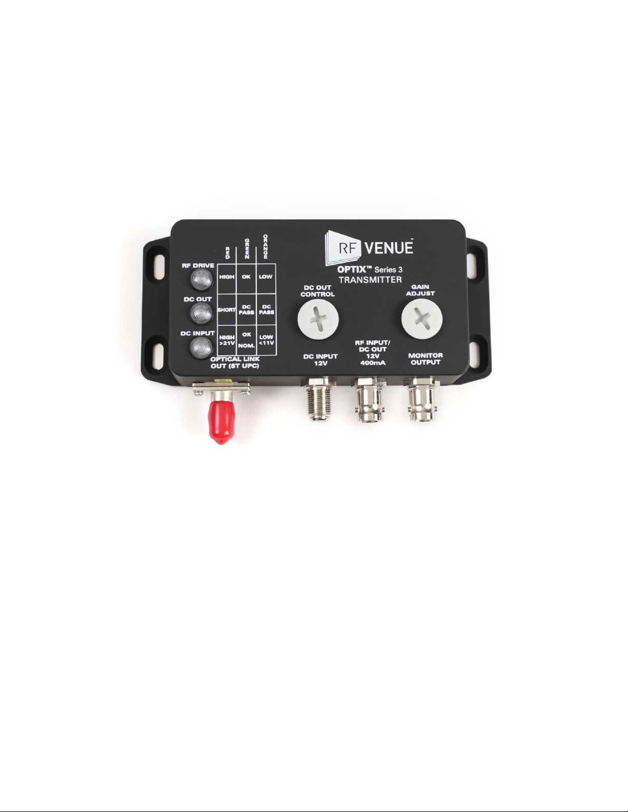
The OPTIX Series 3 Transmitter has three indicator lights, an available monitor output, and two on-board
controls for DC power and gain adjustment.
This Monitor Output is a direct loop from the RF Input port for sampling the input signal on a spectrum
analyzer or connecting to other equipment. The Monitor Output is not affected by the DC Control or the
Gain Adjust.
Page 2
Doc# 70119 Rev 4 2/14/19
2
Transmitter (TX):
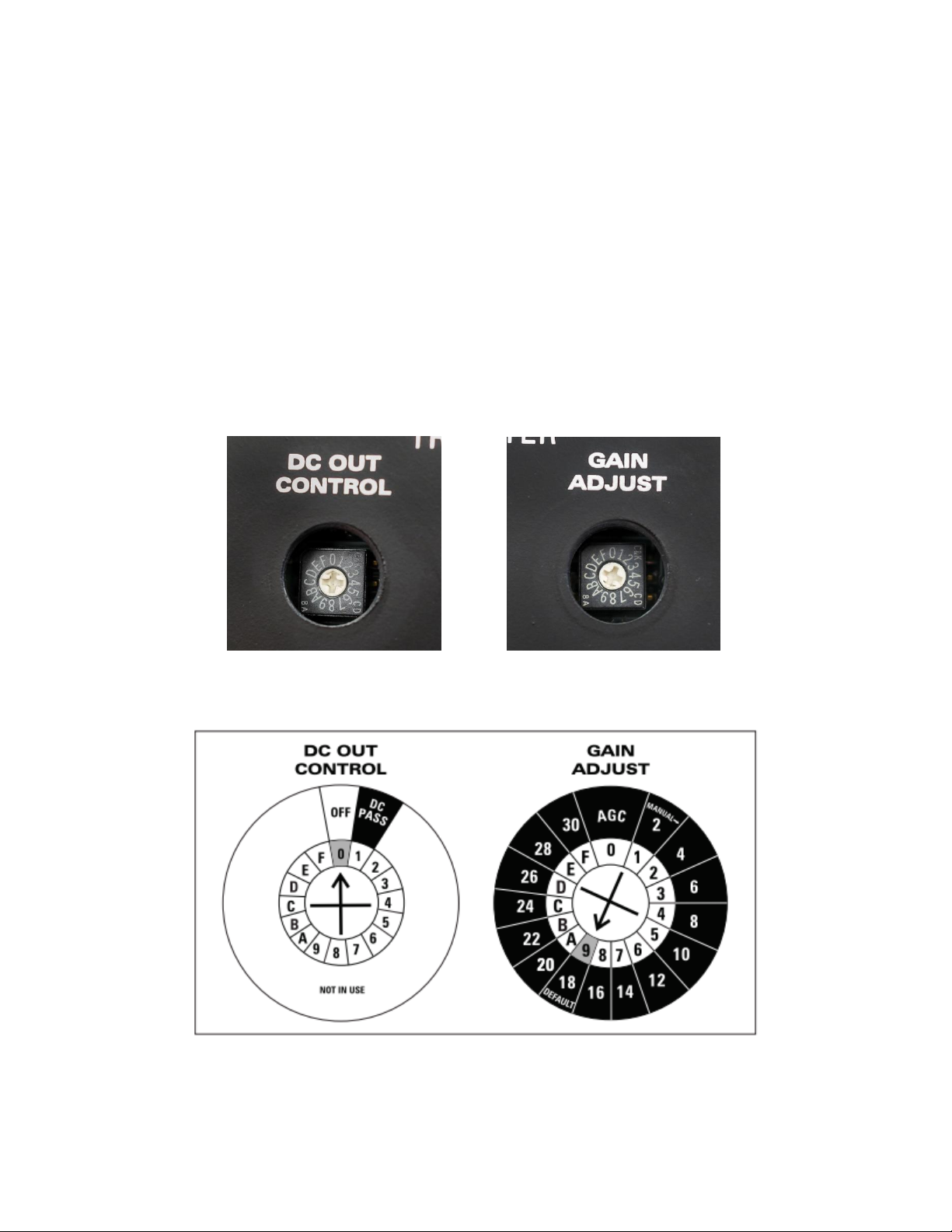
To adjust the settings of the DC Out Control and Gain Adjust, first unscrew the gray removable capplugs. These plugs are threaded and may be removed and installed with a Philips head screwdriver.
When installing, ensure that the plugs are snug to prevent water/dust ingress, but do not over tighten
and distort the rubber o-ring. Adjustments to the user controls are made by turning the 16-position
rotary switch to a specific position using a small Philips head screwdriver (Notice the numbered/lettered
positions and the arrow in the close-up photos).
***Always reinstall the cap-plugs when not adjusting the user controls***
Page 3

Doc# 70119 Rev 4 2/14/19
3
DC Out Control:
The DC Out Control provides DC Voltage to the RF Input/DC Out port. DC Out Control has 5 possible
selections, of which only Positions 0 and 1 are typically used. However, below are the descriptions of
the output for all five positions. NOTE: there is no functionality of Positions 5-9 and A-F. Do not adjust
the control to these positions.
Position 0: the DC Out Indicator Light is off and there is no DC power on the RF Input/DC Output port.
(this is the Preset position)
Position 1: the DC Out Indicator Light is green and the RF Input/DC Output port receives 12VDC.
Position 2: the DC Out Indicator Light flashes green and the RF Input/DC Output port receives 12VDC
with a superimposed 22kHz signal.
Position 3: the DC Out Indicator Light is orange and the RF Input/DC Output port receives 11VDC.
Position 4: the DC Out Indicator Light flashes orange and the RF Input/DC Output port receives 11VDC
with a superimposed 22kHz signal.
Position 2, 3, and 4 are not typically used. At all other positions (5 through F) there is no DC power at the
RF Input port and the DC Out Indicator Light is off.
Gain Adjust:
The Gain Adjust control has 16 possible settings including an Automatic Gain Control (AGC) mode. The
AGC is active at Position 0. It increases or decreases the input signal strength to reach an output of
approximately -35 dBm if the signal is within the AGC hold range of approximately -10 dBm to -40 dBm.
The factory preset is at Position 9. Position A through F each present approximately 2dB of gain for a
maximum of 12 dB, while Position 8 through 1 each present approximately 2dB of attenuation for a
maximum of 16 dB.
***IMPORTANT OPERATING NOTE: Do not use AGC on the TX and the RX at the same time ***
Page 4
Doc# 70119 Rev 4 2/14/19
4
Receiver (RX):
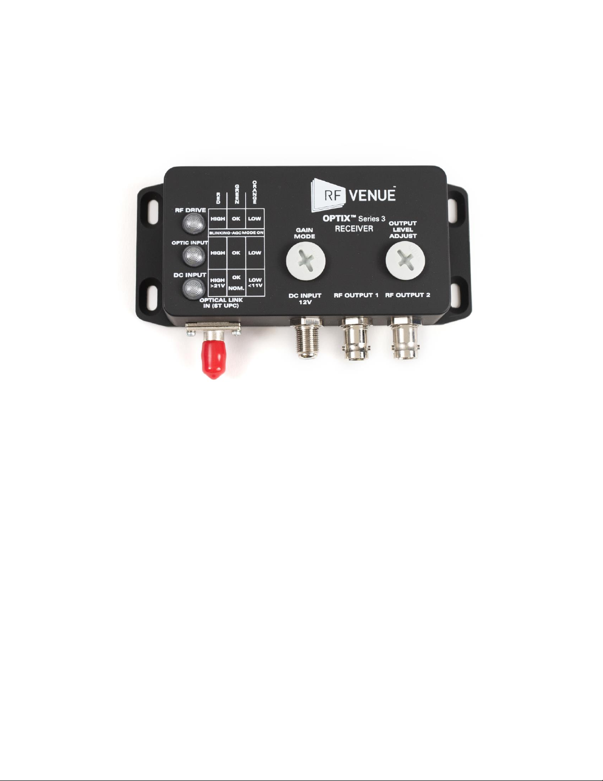
The OPTIX Series 3 receiver has three indicator lights, two on-board controls for Gain Mode and Output
Level Adjust, and two duplicate RF outputs, 1 and 2.
Page 5
Doc# 70119 Rev 4 2/14/19
5
Receiver (RX):
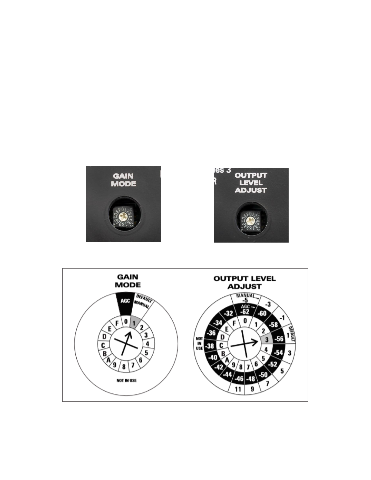
To adjust the settings of the Gain Mode and Output Level Adjust, first unscrew the gray removable capplugs. These plugs are threaded and may be removed and installed with a Philips head screwdriver.
When installing, ensure that the plugs are snug to prevent water/dust ingress, but do not over tighten
and distort the rubber o-ring. Adjustments to the user controls are made by turning the 16-position
rotary switch to a specific position using a small Philips head screwdriver (Notice the numbered/lettered
positions and the arrow in the close-up photos).
***Always reinstall the cap-plugs when not adjusting the user controls***
Page 6

Doc# 70119 Rev 4 2/14/19
6
Gain Mode:
The Gain Mode has 2 options, Automatic Gain Control (AGC) and Manual Gain Control.
Position 0: Automatic Gain Mode – the output signal is kept constant (as long as the input signal is
within the AGC hold range).
Position 1: Manual Gain Mode – the output signal changes relative to input signal changes. (this is the
Preset position)
Do not set Gain Mode to anything other than 0 or 1, as doing so may run the risk of misconfiguration.
***IMPORTANT OPERATING NOTE: Do not use AGC on the TX and the RX at the same time ***
Output Level Adjust:
The Output Level Adjust has 16 selectable positions in Automatic Gain Mode (Gain Mode Position 0) and
9 selectable positions in Manual Gain Mode (Gain Mode Position 1). In Manual Gain Mode (Position 1)
the Output Level Adjust attenuates/amplifies the signal from -5 to +11 dB in 2dB steps; Positions 9
through F are not used. In Automatic Gain Mode (Position 0) the Output Level Adjust changes what
level the output is held to from -62 dBm to -32 dBm (also in 2dB steps). The input signal must be within
the AGC hold range to maintain a consistent output. The factory preset position is 3.
Page 7
Doc# 70119 Rev 4 2/14/19
7
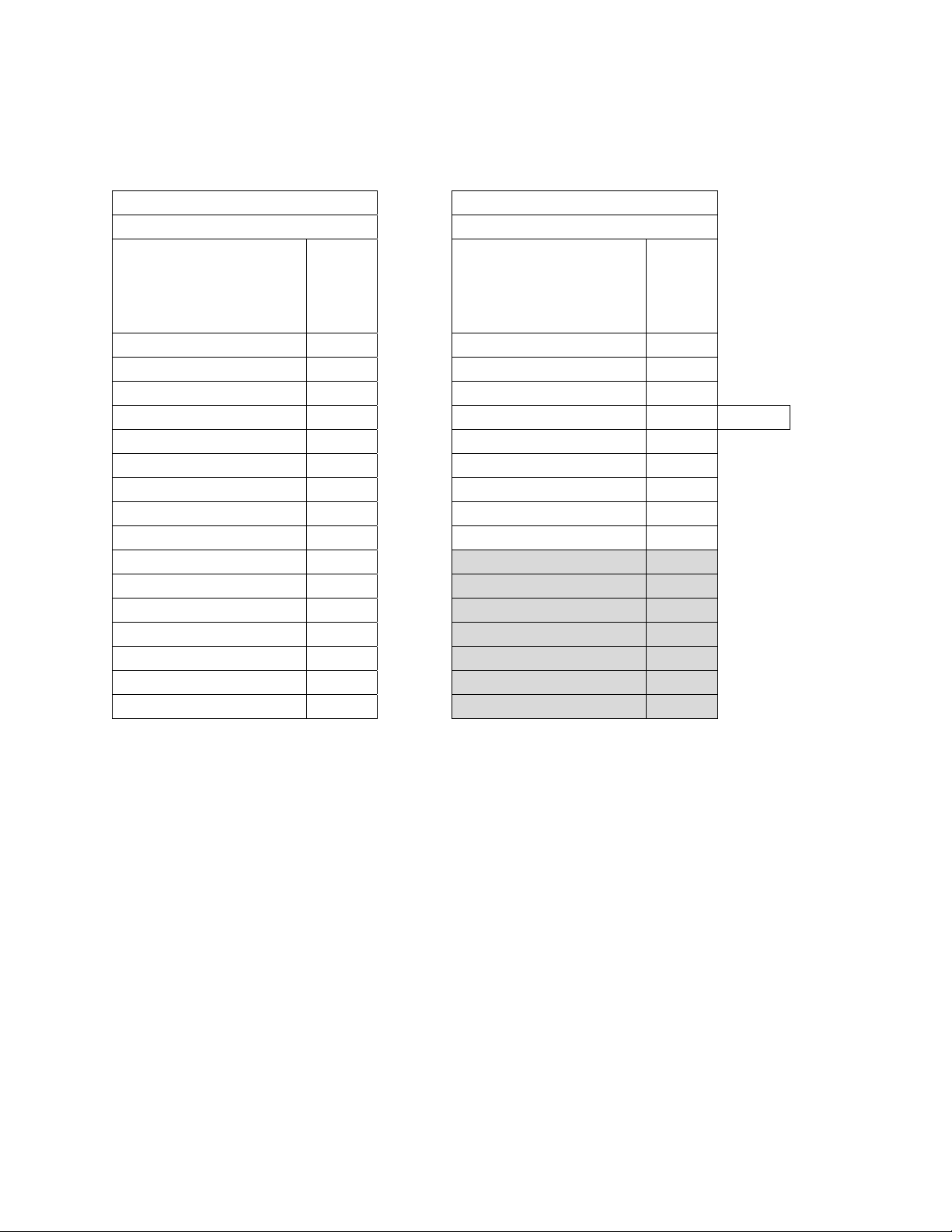
Two lists of sample measurements from a -35.62 dBm input signal at 526 MHz in Manual Gain Mode and
Automatic Gain Mode are shown below:
Automatic Gain Mode
Manual Gain Mode
(Gain Mode Position 0)
(Gain Mode Position 1)
Output Level Adjust
Position:
Output:
Output Level Adjust
Position:
Output: 0
-62.31 0
-42.38 1
-60.78 1
-40.35 2
-59.45 2
-38.42
3
-58.40 3
-36.37
(Preset)
4
-56.85 4
-34.34 5
-55.54 5
-32.29 6
-52.90 6
-30.31 7
-50.85 7
-28.28 8
-48.87 8
-26.60 9
-47.23 9*
-26.21 A
-45.74 A*
-27.76 B
-44.23 B*
-28.03 C
-42.29 C*
-27.93 D
-40.26 D*
-28.19 E
-39.21 E*
-28.60 F
-37.20 F*
-29.11
*Position not used (Note: while you can see some change in the output in these positions, the unit’s
controls are not intended to provide any operating benefit for these positions, so the output results are
not indicative of performance)
 Loading...