

Page 1
59010-531-01
4ZONE 4 Zone Antenna Combiner for Wireless Microphones
Operation
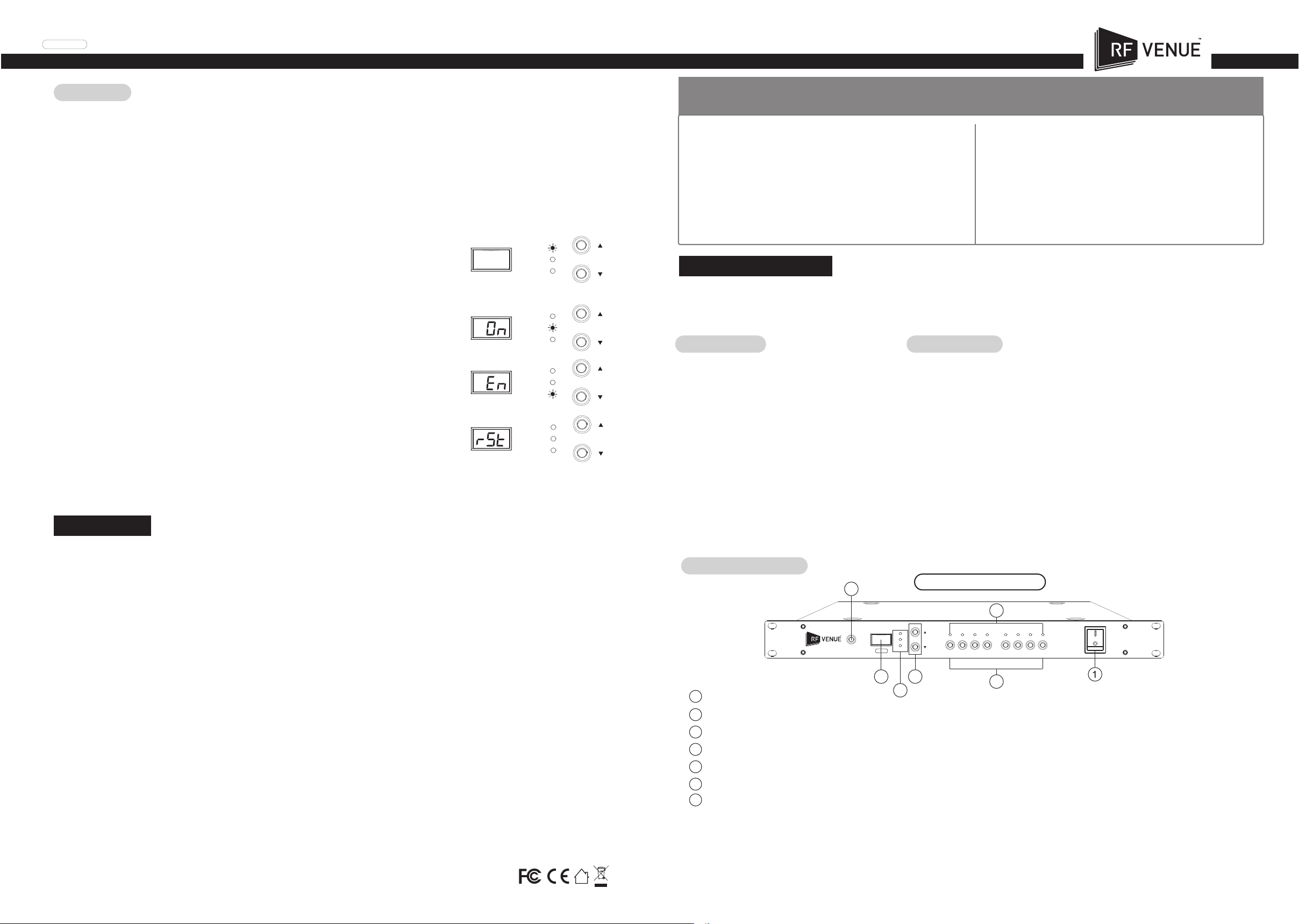
To enter the settings mode, press and hold the desired input channel’s Antenna Selection key ② for 2 seconds until the input
channel’s indicator light ashes. Use the Antenna Selection key to cycle through the 3 settings menus as indicated by the Settings
Selection Indicator ⑥. Use the Up / Down keys ③ to change the parameters in each settings mode. After setting your
parameters in the third settings mode (RF Input), press the Antenna Selection key a nal time to save and exit the settings. For a
step by step video, please visit rfvenue.com.
Setting Parameters:
RF input attenuation
Press the up / down key to adjust the input attenuation in 1dB increments.
0dB: No attenuation
-10
Attenuation of 10dB
RF Attenuation
DC Power
Input ON/OFF
Maximum attenuation level is - 31dB per input channel
Antenna DC power
On (applies +12V DC / 200mA to RF input channels for active antennas or in-line ampliers)
OFF
RF Input ON/OFF
En: Input Enabled
dis: input disabled; signal isolation ~ 80 dBm
To Return to Default Settings
1. Turn off the power
2. Press and hold the Lock Key
DC Power
RF Input Enable
RF Attenuation
DC Power
Input ON/OFF
RF Attenuation
DC Power
Input ON/OFF
RF Attenuation
DC Power
Input ON/OFF
3. Turn on the power while continuing to hold the lock key until the display show rSt
Notes
• This product is designed for combining receive antennas for wireless microphone receivers and is not recommended for use with transmitters.
• Use standard 50Ω coaxial cable.
• An In-Line Amplier may be used to compensate for losses associated with long runs of coaxial cable. Enable DC power when using ampliers.
• Adjust the RF input attenuation levels if signals exceed normal ranges of wireless microphone receivers.
Caution : To reduce the risk of re or shock hazard, do not expose this appliance to heat or moisture.
Warning : To prevent electric shock, do not remove the cover. Refer all servicing to qualied service personnel or distributors.
Read this instruction manual before using.
Keep this instruction manual for future reference.
•Use in a well ventilated area. Do not block any ventilation openings.
•Do not use near heat sources.
•Do not use in humid or dusty environments.
•Turn power off immediately in the event of a spill or if the unit overheats.
Instruction Manual
The 4ZONE is designed to combine multiple pairs of diversity antennas used for wireless microphone receivers. It provides 2
x 4 antenna inputs to maximize coverage areas. It features RF input ON/OFF, input attenuation from 0 dB to -31 dB, DC
power for in-line ampliers or active antennas, and individual input signal ON/OFF control.
Accessories
• AC Power Cable x1
• BNC to BNC coaxial Cable x2
Operating Controls
4
Lock
4ZONE
4 Zone Antenna Combiner
Specifications
• Carrier Frequency Range: 470~960MHz
• Full System Gain: 3dB(±3dB)
• Input/Output Impedance: 50 Ω
• A/B Antenna Input:4+4
• OIP3: -35dBm(typ.) @ 2-tone;Pi=-15dBm/tone
• RF Input Attenuation: -31~0dB (Step:1dB)
• Input/Output Connectors: BNC(F):Input x8 / Output x2
• Functions:
1. DC Power (for In-Line Amplier) ON/OFF Control
2. RF Input Attenuation Control
3. RF Input Signal ON/OFF Control
• In-Line Amplier Power: 12V/200mA*8
• Power Supply: 100~240VAC; MAX 2A 50/60Hz
• Dimension(mm): 480mm(W)*45mm(H)*260mm(D)
4ZONE Front Panel
7
RF Attenuation
DC Power
Input ON/OFF
A1 A2 A3 A4 B1 B2 B3 B4
35
1
Power switch
Antenna Selection key: Select the CH to be set, press and hold for 2 seconds to enter the settings mode.
2
Up / Down key: In the settings mode, press the up / down key to select the parameter.
3
Lock key: press and hold for 2 seconds to lock or unlock panel key function
4
3-digit display
5
Settings Selection Indicator
6
7
Status indicator: Indicates the current antenna status,
6
2
a. Red: RF input enabled, In-Line Amplier power on.
b. Green: RF input enabled, In-Line Amplier power off.
c. Off: The antenna input is disabled.
d. All 8 channels ashing at the same time: Power supply is abnormal. Please shut down immediately.
14
Page 2
100-240VAC~
50/60Hz, 2A
FUSE: T3.15A/250V
11
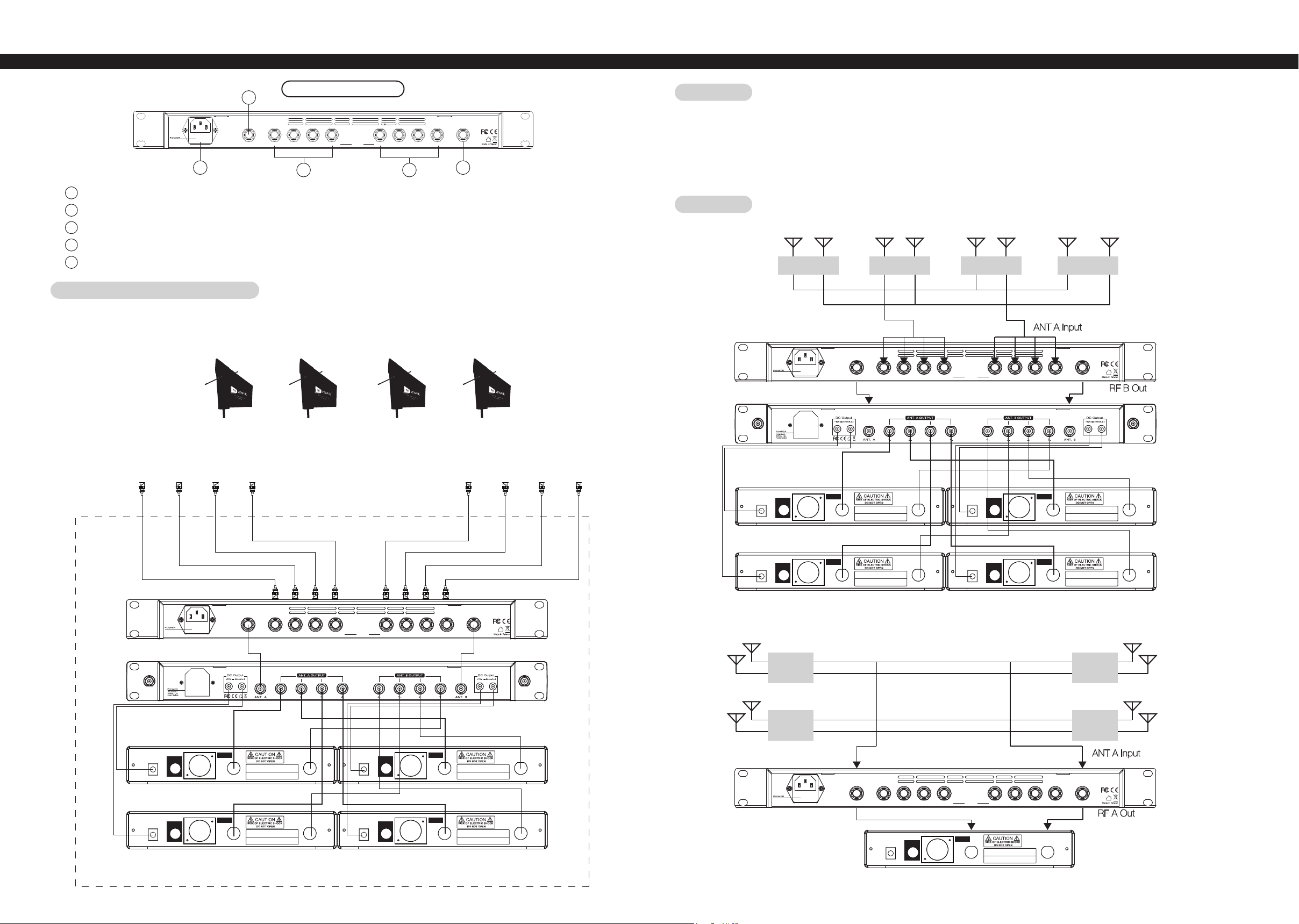
4ZONE Rear Panel
RF OUT A RF OUT BB4 B3 B2 B1 A4 A2 A1A3
RF INPUT
Installation
• Connect the antenna to the antenna inputs of the 4Zone with a coaxial cable. Long cable runs may require an In-Line Amplier.
• Connect the antenna outputs to the receiver or antenna distributor with a coaxial cable.
• When not in use, store the 4Zone with the power off.
8 9
8
AC power supply: AC power input: 100 ~ 240VAC, MAX 2A, 50 / 60Hz.
9
Antenna B output
10
Antenna A inputs
11
Antenna A output
Antenna B inputs
12
12 10
4ZONE Antenna Configuration
DFIN1 DFIN4DFIN3DFIN2
Diversity Fin
Antenna
Input
A1 & B1
Input
A2 & B2
Input
A3 & B3
Input
A4 & B4
A4 A1A2A3B1B2B3B4
Application
EX 1.
DCV INPUT
12-18V/500mA
B1
A1 B2 A2 B3 A3 B4 A4
STUDIO 1 STUDIO 2 STUDIO 3 STUDIO 4
100-240VAC~
50/60Hz, 2A
FUSE: T3.15A/250V
ANT B Input
RF OUT A RF OUT BB4 B3 B2 B1 A4 A2 A1A3RF INPUT
ANT A Input
RF A Out
AF OUTPUT
UNBAL .
AF OUTPUT
BALANCED
Freq. Range:
A1 B1 A2 B2
Serial No.:
ANT. 1ANT. 2
DCV INPUT
12-18V/500mA
AF OUTPUT
UNBAL .
AF OUTPUT
BALANCED
Freq. Range:
Serial No.:
RF B Out
ANT. 1ANT. 2
DCV INPUT
12-18V/500mA
DCV INPUT
12-18V/500mA
100-240VAC~
50/60Hz, 2A
FUSE: T3.15A/250V
AF OUTPUT
UNBAL .
AF OUTPUT
UNBAL .
RF OUT A RF OUT BB4 B3 B2 B1 A4 A2 A1A3RF INPUT
AF OUTPUT
BALANCED
Freq. Range:
A1 B1 A2 B2
Serial No.:
AF OUTPUT
BALANCED
Freq. Range:
A3 B3 A4 B4
Serial No.:
ANT. 1ANT. 2
ANT. 1ANT. 2
DCV INPUT
12-18V/500mA
DCV INPUT
12-18V/500mA
AF OUTPUT
UNBAL .
AF OUTPUT
UNBAL .
AF OUTPUT
BALANCED
AF OUTPUT
BALANCED
Freq. Range:
Serial No.:
Freq. Range:
Serial No.:
Wireless Microphone Receivers
DCV INPUT
12-18V/500mA
AF OUTPUT
UNBAL .
AF OUTPUT
BALANCED
Freq. Range:
A3 B3 A4 B4
Serial No.:
ANT. 1ANT. 2
DCV INPUT
12-18V/500mA
AF OUTPUT
UNBAL .
AF OUTPUT
BALANCED
Freq. Range:
Serial No.:
ANT. 1ANT. 2
EX 2.
B1
A1
AREA 1
AREA 2
B3
A3
AREA 3
ANT B Input
ANT. 1ANT. 2
100-240VAC~
50/60Hz, 2A
FUSE: T3.15A/250V
RF OUT A RF OUT BB4 B3 B2 B1 A4 A2 A1A3RF INPUT
AREA 4
ANT A Input
RF B Out
AF OUTPUT
ANT. 1ANT. 2
DCV INPUT
12-18V/500mA
AF OUTPUT
UNBAL .
BALANCED
Freq. Range:
B A
Serial No.:
ANT. 1ANT. 2
B2
A2
B4
A4
RF A Out
32
 Loading...