

Page 1
Form I-ZQYRA RB5 Display
.219”
(6mm)
1.125”
(29mm)
.91”
(23mm)
3.13” (80mm)
1.56”
(40mm)
(2) Cable Splitter and Signal
Booster Modules, P/N 260735
(2) 6-pin Connection
Cables, P/N 260175
2.75 (70mm)
6 0
A
B
SC
C
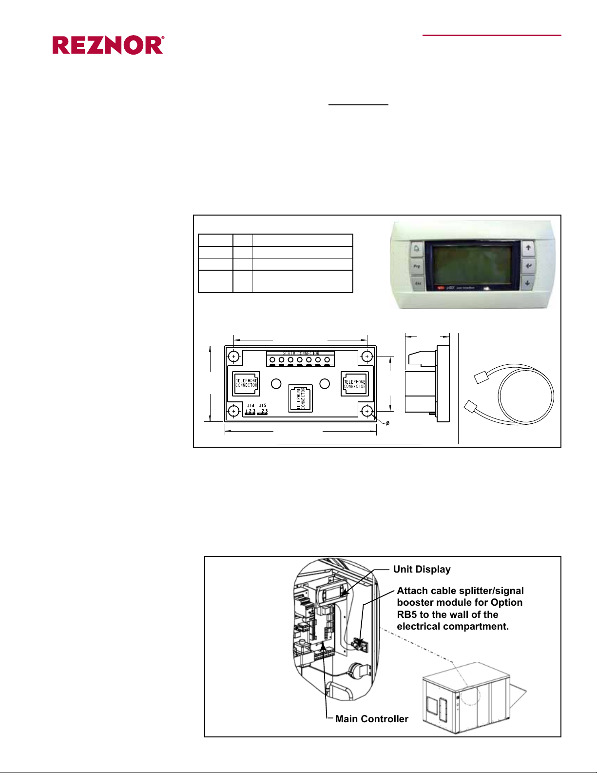
Front and Side Views with Dimensions
Unit Display
Main Controller
Attach cable splitter/signal
booster module for Option
RB5 to the wall of the
electrical compartment.
Installation of Option RB5,
Remote Mounted Display
Applies to: Z Series Model ZQYRA
Ventilation Unit
Description and
Application
Option
Components
The factory-installed display in the electrical control compartment allows complete
access to unit test features, schedules, discharge air setpoints, fan control, alarms,
and other unit operational setpoints. Option RB5 is a second, remote-mounted display
that can be eld-installed up to 656 ft (200M) from the unit allowing the same unit
access. NOTE: If the remote display needs to be mounted more than 656 ft (200M)
from the unit, contact the factory about adding a eld-supplied power supply required
to extend the range up to 1500 ft (457M).
Component List
P/N Qty Description
260178 1 Unit Display
260175 2 6-pin Connection Cable
260735 2
Cable Splitter and Signal
Booster Module
Unit Display, P/N 260178
Field-Supplied
Requirements
Installation
Instructions
Field-supplied 22 AWG to 18 AWG twisted pair wire (EIA 485) and an electrical junction
box are required.
1. Turn power off to the unit (lock the disconnect switch open).
2. Install one Cable Splitter and Signal Booster Module inside the Cabinet
a) Remove the electrical compartment access panel. Position one of the cable
splitter/signal booster modules (P/N 260735) on the wall of the electrical
compartment as illustrated. Attach it with the screws provided.
Upper Right
Corner of
the Electrical
Compartment
I-ZQYRA RB5 Display, P/N 260737, page 1
Page 2
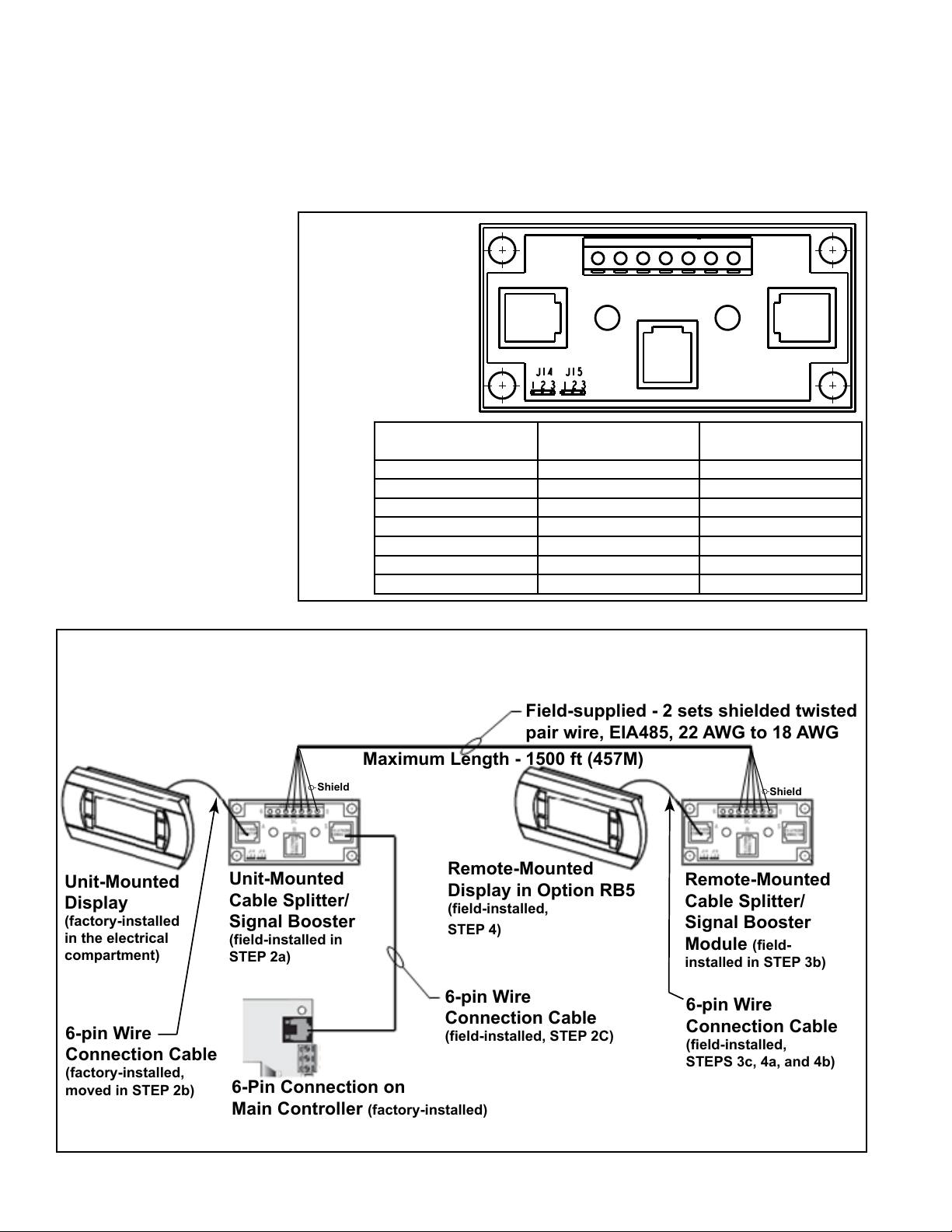
Remote-Mounted
Cable Splitter/
Signal Booster
Module
(field-
installed in STEP 3b)
6-pin Wire
Connection Cable
(factory-installed,
moved in STEP 2b)
6-pin Wire
Connection Cable
(field-installed, STEP 2C)
Maximum Length - 1500 ft (457M)
6-Pin Connection on
Main Controller
(factory-installed)
6-pin Wire
Connection Cable
(field-installed,
STEPS 3c, 4a, and 4b)
Field-supplied - 2 sets shielded twisted
pair wire, EIA485, 22 AWG to 18 AWG
Shield
Shield
Unit-Mounted
Display
(factory-installed
in the electrical
compartment)
Remote-Mounted
Display in Option RB5
(field-installed,
STEP 4)
Unit-Mounted
Cable Splitter/
Signal Booster
(field-installed in
STEP 2a)
Installation
Wiring Connections
on Cable Splitter
and Signal Booster
Module, P/N 260735
6 0
Plug
A
Screw Terminals
Plug
B
Plug
C
Instructions
(cont’d)
b) In the electrical compartment, nd the unit display and the main controller below
it (see illustration on page 1). At the main controller, locate and unplug the 6-pin
connection cable (the cable that connects from the unit display to the controller).
Move the disconnected end of the cable to the module installed in Step 2a) and
connect it to plug “A” (see illustration below).
c) Install one of the new 6-pin connection cables (P/N 260175), connecting one
end to the main controller and the other to plug “C” (see below) on the module
installed in Step 2a).
Terminal Screw
Connection
0 = Earth
1 1 +VRL=30 Vdc
2 2 GND
3 3 Rx-/Tx-
4 4 Rx+/Tx+
5 (not used) 5 (not used) GND
6 (not used) 6 (not used) +VRL=30 Vdc
Pictorial Installation of Option RB5, Remote Display
Pin Telephone
Connection
Meaning
I-ZQYRA RB5 Display, P/N 260737, page 2
Page 3

3. Install the second Cable Splitter/Signal Booster Module at the Remote
Location
a) Determine the desired location for the remote display unit. It can be located up
to 656 feet (200M) from the unit.
Using eld-supplied 22 AWG to 18 AWG shielded twisted pair wire (EIA
485), run dedicated wires from that location to the unit. Two sets of twisted
pair wire are required -- one for the power and one for communication. The
communication wire should be shielded to prevent noise.
On the cable splitter/signal booster module installed in Step 2a), connect the
shield to screw terminal 0. Connect the power wires to screw terminals 1 and 2.
Connect the communication wires to terminals 3 and 4.
b) Install the second cable splitter/signal booster module (P/N 260735) in a eld-
supplied junction box to be recessed behind the remote display. Connect the
shield to screw terminal 0. Connect the power wires to terminals 1 and 2 and
communication wires to terminals 3 and 4, making sure that power and commu-
nication polarity is maintained.
WARNING: Improper wiring can damage the remote unit interface
display as well as the main system controller.
c) Attach the second 6-pin connection cable (P/N 260175) in the kit to plug “A” on
the remote cable splitter/signal booster module.
4. Install the Remote Display
a) Remove the back cover of the remote unit interface display (P/N 260178).
Position the back cover over the cable splitter/signal booster module installed in
Step 3b) and feed the 6-pin connection cable out through the hole in the cover
plate. Mount the back cover plate to the wall covering the cable splitter/signal
booster module.
b) Unsnap the face cover from the remote unit interface display. Locate the 6-pin
wire connection and connect the cable from the cable splitter/signal booster
module. Using the screws removed, re-attach the display to the back cover
plate. Snap the display face cover in place.
5. Verify power and communication polarity before re-powering the unit.
6. Turn power on to the unit. Set the Address of the Remote Display.
a) All displays have a factory-set address of 32; therefore, the address of the
remote display must be changed. To access conguration mode on the
remote display, press the UP
hold all three for at least 5 seconds. The display on the remote unit will be
similar to the one shown below, with the cursor ashing in the top left corner.
b) To change the address of the remote display (“Display address setting”), .follow
these steps.
1) Press the ENTER
setting” eld.
2) Using the DOWN
again to conrm the setting. The following screen will be displayed and the
new address will be saved to the permanent memory.
button once; the cursor will move to the “Display address
button, change the display address to 31. Press ENTER
, DOWN , and ENTER buttons and
I-ZQYRA RB5 Display, P/N 260737, page 3
Page 4

Installation
Instructions
(cont’d)
c) The list of terminals associated with main control module is set at the factory and
should not need to be adjusted. If access is needed, the following procedure can
be used.
Access conguration mode on the remote display (press UP
and ENTER
I/O Board Address” eld should remain at the default setting of “01”. Press the
ENTER
the terminal conguration screen as shown below. This screen tells the controller
what each of the terminal addresses are. The rst terminal should be at 32 and
the second terminal will be at 31.
To exit the conguration procedure and save the data, select the “OK?” eld, set
“Yes”, and conrm by pressing the ENTER
7. Check the remote display for proper operation.
buttons and hold all three for at least 5 seconds). NOTE: The
button four times to bypass the display address screen and move to
button.
, DOWN ,
I-ZQYRA RB5 Display, P/N 260737, page 4
www.ReznorHVAC.com
(800) 695-1901
©2014 Reznor, LLC. All rights reserved.
Trademark Notes: Reznor
All other trademarks are the property of their respective owners.
0514 Form I-ZQYRA RB5 Display (Version 0.1)
®
is registered in at least the United States.
 Loading...