

Page 1
1. Always include complete heater model and serial number
IMPORTANT
so that any specication change can be considered for
parts replacement. It can save time and expense.
2. Specications are subject to change without notice.
3. We reserve the right to substitute functional replacements.
4. Order by P/N; not Heater Option Designation.
A
Air Temp Sensor w/ 8”Probe 20
B
BacNet DDC Communication
Bus 11
See also Electri-
cal Components - Low
Voltage Panel
Blocked Condensate Switch
(High Efciency Furnace)
11
Building Static Pressure (in Opt
VFC4 & GF5) 11
Bypass Valve 42
C
External Cabinet Parts 48,
49, 50
Cabinet Sizes 1, 2 & 3
• Model YDHA:
• Cabinet Size 1 - DX
Cooling Sizes 60, 90, 120
& 150.
• Cabinet Size 2 - DX
Cooling Sizes 180, 210
& 240.
• Cabinet Size 3 - DX
Cooling Sizes 300 & 360.
• Model YDMA:
• Cabinet Size 1 - DX
Cooling Sizes 60, 90, 120
& 150.
• Cabinet Size 2 - DX
Cooling Sizes 180, 210
& 240.
• Cabinet Size 3 - DX
Cooling Sizes 300 & 360.
• Model YDSA:
• Cabinet Size 2 - Sizes 120
& 150.
• Cabinet Size 3 - Sizes 180
& 210
Capacitor 11, 16
Carel Digital Controller 16
Carel Digital Controller with
Programmed Software 11
Carel Plugs 11, 16
CO2 Sensor 11, 20
Condenser Coil 36, 41
Evaporator Coil 36, 41
Coil & Filter Access Panel 50
Coil Kit (24v Coil) 34
Combination Gas Valve 22
Compressor 34, 40, 41, 45
Compressor Mounting Kit
33, 42
Compressor Sound Blanket 34
Condenser Fan Installation &
Fan Support 34
Condenser Fan System 36, 37
Condenser Top 36
Contactor 11, 17, 45
Control Left Door 49, 50
SCR Controller 17
Control Right Door 49, 50
Convenience Outlet 11, 20
Cooling and Dehumidifying
Components 37, 38, 40,
41, 42
Crankcase Heater 35, 41
Cross-Reference by Model/Size
and Cabinet Size 4
D
Damper Ball & Socket Joint 44
Damper Linkage 44
Damper Motor Access Cover
50
Dampers and Controls 43, 44,
47, 48
Date of Manufacture 3
Digital Controller 11, 33, 34,
40, 41
Digital Controller for Compres-
sors 12
Dirty Filter Switch 11
Discharge Air Sensor 11
Disconnect Switch (Option
CP) 20
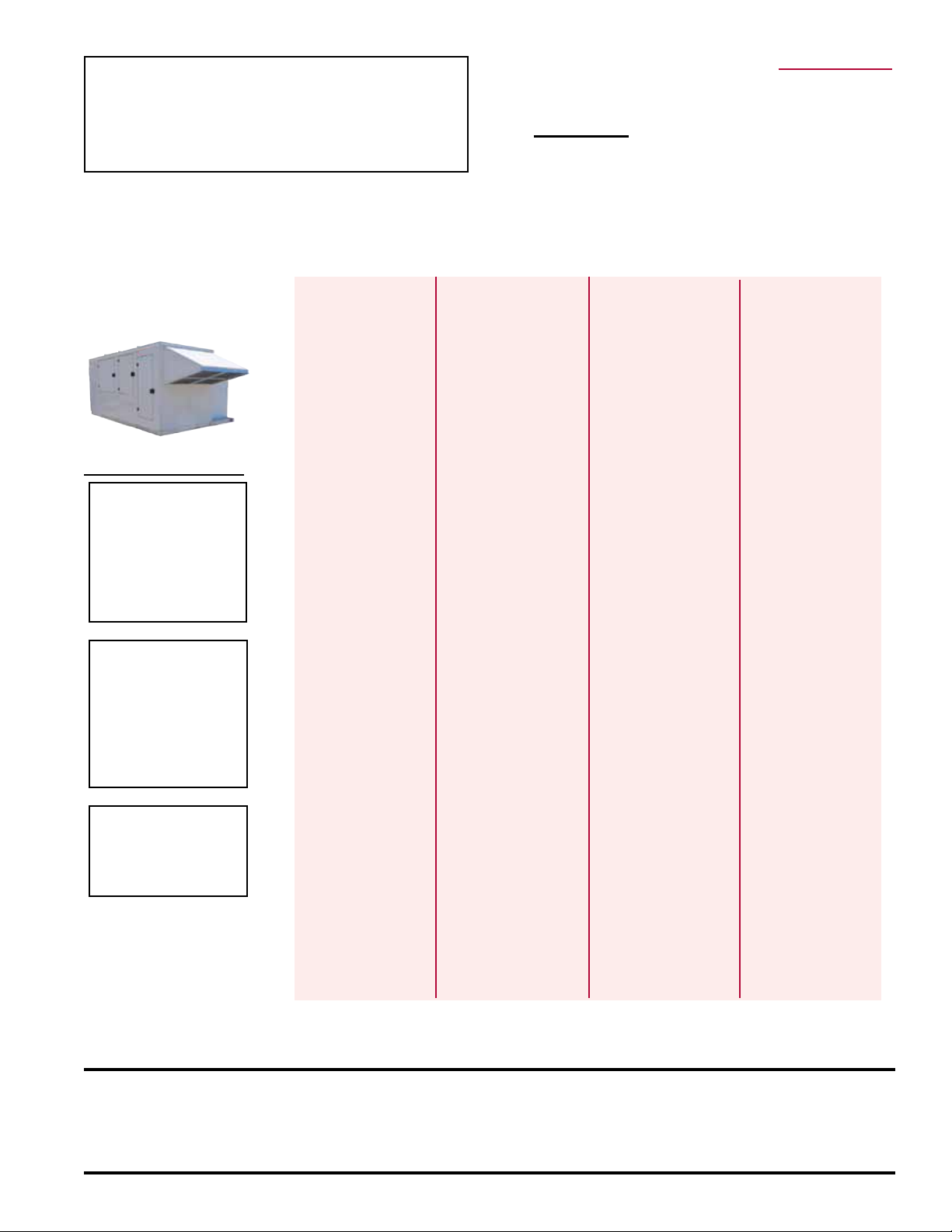
Applies to: Replacement Parts for
Models YDHA, YDMA, and YDSA
Cabinet Sizes 1, 2 & 3.
INDEX
Hand Held Display for Digital
Controller (Opt RB4) 11
Remote Display for Digital Con-
troller (Option RB3) 11
Distribution Block 11
Distribution Block, 17
Drain Access Outer Panel 50
Drain Pan 51
DSI Control Module 11, 20
Ductstat 11
Duct Static Pressure (in Option
VFC3) 11
E
Electrical Compartment 4, 5,
6, 7, 8, 9, 10, 20, 21, 22,
24, 26
Electrical Components - Electric
Heat Section Panel 11
Electrical Components - High
Voltage Panel 11
Electrical Components - Unit
Low Voltage P 11
Electric Preheat Energy Recov-
ery Wheel, Options PH2A,
PH3A or PH4A 45
Energy Recovery Cassette 44
Energy Recovery Filter Switch
11
Energy Recovery Wheel Access
Panel 50
Energy Recovery Wheel Filters,
Options EW30, EW36,
EW46 or EW58 42
Energy Recovery Wheel Pack-
age Components 44,
45, 46
Exhaust Fan Pressure Switch
11
Expansion Valves 35, 41
F
Fan Access Panel 50
Fan Blade 36
Fan Guard 36
Fan Motor, 3/4 HP 36
Fan/Motor Support 36
Dirty Filter Switch 44
Filter Drier 35, 41
Filter Pressure Switch, 17
Filter Support Asm Comp 43
Firestat 11, 20
Flame Sensor 22, 23, 24,
25, 26
Flexible Gas Connection 23,
25, 26
Frostat 44
Fuse 45
Fuseblock 45
Fuses 11
Fuses for wheel preheat (opt
PH-__) 11
G
Gas Door Left 49
Gas Door Right 50
Gas Orice Replacement 28
Obsoletes Form P-Y (5-16)
Gas Pressure Switch 24,
25, 26
Gas Valve 23, 25, 26, 27
Grounding Bar 12
Grounding Lug 11, 16
H
Hail Guard 51
Heater Rack 45
Heat Exchanger Assy 22, 23,
24, 25, 26
High Gas Pressure Switch 22,
23, 24, 25, 26
High Pressure Switch 34, 41
Hinge 51
I
Ignitor 22, 23, 24, 25, 26
IQ Digital Controller 11
Isolation Hardware on Fan
Support 34
L
Limit Control 22, 23, 24, 25, 26
Line Reactor 11, 16
Long Damper Rod 44
Low Ambient Controller for
ECM Condenser Fan 16
Low Ambient Controller for
ECM Condenser Fan (Opt
CUF4) 11
Low Ambient Controller for
Standard Condenser Fan
(Opt CUF3) 11
Low Ambient Controller for
Std Condenser Fan Sen-
sor 16
Low Gas Pressure Switch 22,
23, 24, 25, 26
Low Pressure Switch 34, 41
Low Speed Venter (Combustion
Air Switch - Low Pres-
sure) 11
M
Modulating Valve 24, 25, 26
Molded Plug 35, 41
Damper Motor 44
Motor Bracket 44
Mounting Kit 34, 41
O
Option AG72 & 74 Gas Heat
Components 23, 25, 26
OPTIONAL GAS HEAT SEC-
TION, Option H_ 34
Optional Gas Heat Section Rat-
ing Plate 3
Outside Air Hood, Option
AS16 43
Overload Relay 11
P
Phase Loss/Voltage Monitor 12
Phase Loss/Voltage Monitor
(Opt PL4) 11
Photoelectric Smoke Detector
20
Plenum Fan 36, 37
Form P-Y (6-16)
Plug-in Card 11
Power Feed Terminals 12
Pressure Sensor Transducer
11
R
Rating Plate 2
References 52
Relay 11
Relay Board 11, 20
Return Air Temperature Sensor
& Box, 8” probe 11
Rubber Isolation 37
S
SCR Controller 11
Sensor Port 17
Sensors for Monitoring and
Reporting to the Digital
Controller 11
Serial No. 2
Serial No. Date of Manufacture
Table 3
Shaft 44
Slam Latch 51
Smoke Detector 11
Socket for Code 1A Moni-
tors 11
Solenoid Kit 33, 42
Solenoid Kit (24v Coil) 34, 41
Space Temperature Sensor
(Opts CL23, CL33 &
CL78) 11
Space Temp Sensor 20, 27, 33
Static Pressure Transducer 17
Supply Air Filters, Options
AW21 or AW24 42
Supply Fan 11
Air Proving Switch 11, 16, 17
Combustion Air Proving Switch
11, 17
Dirty Filter Pressure Switch 11
Disconnect Switch 11, 20
T
Temp Sensor (18”) 11, 20
Temp Sensor (36”) 11, 20
Temp Sensor (Wheel Supply
Air) 44
Terminal Blocks 11
Terminal Strip 11, 17
Thermister 33, 34, 40, 41
Top Cover Center 49
Top Cover End 49
Top Cover Rear 49
Transducer 11
Transformers 11, 12
V
Vent Box Subassembly 51
Venter Housing 11
VFD 11
W
Wheel Belt 44
Wheel Segment 44
Wiring Harness 44
IMPORTANT: Do not release refrigerant to the atmosphere! If required service
procedures include the adding or removing of refrigerant, the service technician
must comply with all federal, state, and local laws. Service procedures should only
be performed by a qualied HVAC technician.
Form P-Y (6-16), PN 273651R23, Page 1
Page 2
DANGER
This unit contains R-410A high pressure refrigerant. Hazards exist that could result
in personal injury or death. Installation, maintenance, and service should only be
performed by an HVAC technician qualied in R-410A refrigerant and using proper
tools and equipment. Due to much higher pressure of R-410A refrigerant, DO NOT
USE service equipment or tools designed for R22 refrigerant.
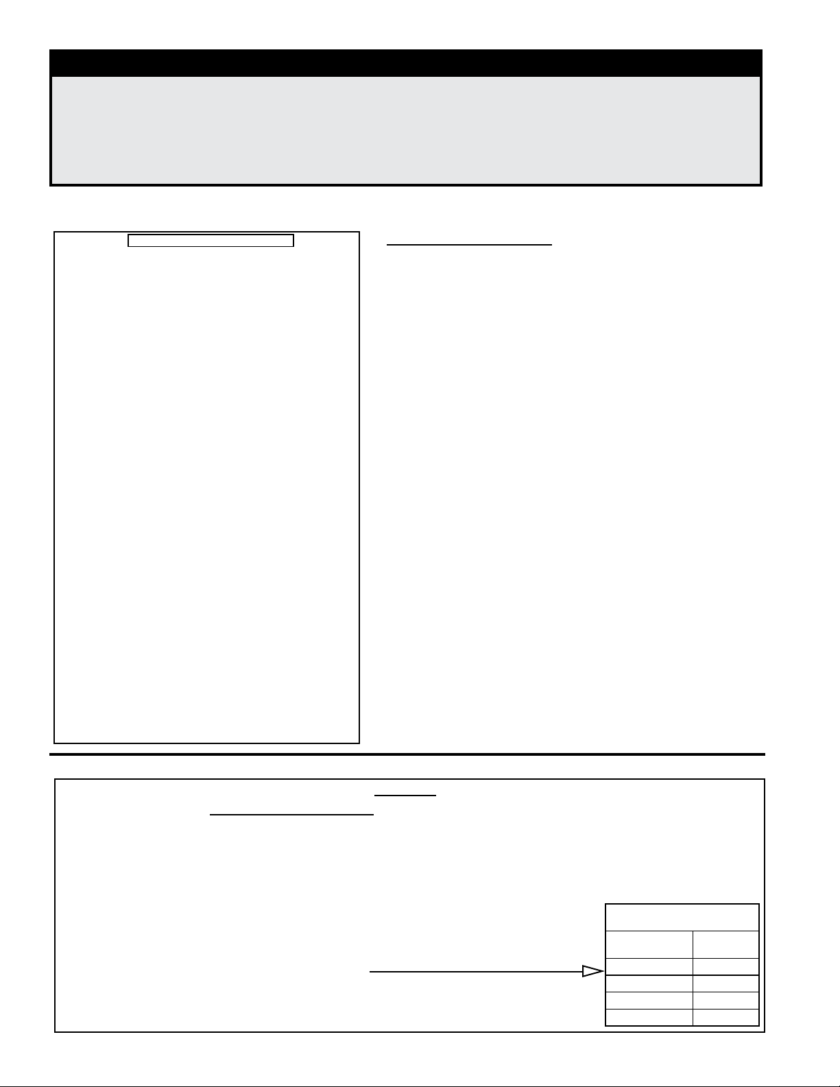
Rating Plates and Serial No.
Sample of System Rating Plate (applies to all Y series models)
RAD
FOR INDUSTRIAL/COMMERCIAL USE ONLY
SUITABLE FOR OUTDOOR USE
MODEL [ A ] [ B ]
SERIAL NO. [ ]
[D] VOLTS +/- 10% [D] PHASE [D] HZ
MINIMUM CIRCUIT AMPACITY (MCA) [ F ] AMPS
MAXIMUM FUSE SIZE/*CKT BREAKER [ G ] AMPS
SHORT-CIRCUIT CURRENT: 5,000 A RMS SYMMETRICAL [D] V MAX.
MAXIMUM OUTLET TEMPERATURE [ X ]
SUPPLY AIR BLOWER MOTOR 1 [ E ] [ C ]
CONDENSER FAN MOTOR (S) [ T ] [ U ] [ Z ]
COMPRESSOR A [ H ] [ I ] [ J ]
COMPRESSOR B [ K ] [ L ] [ M ]
COMPRESSOR C [ N ] [ O ] [ P ]
COMPRESSOR D [ Q ] [ R ] [ S ]
COMPRESSOR LOW ENTHALPY [ GG ] [ HH ] [ JJ ]
COMPRESSOR HIGH ENTHALPY [ KK ] [ LL ] [ MM ]
REFRIGERANT - R-410a CHARGE - LBS
TEST PRESSURES HIGH 600 PSIG LOW 45 PSIG
EQUIPPED FOR OPERATION AT AN AIR FLOW OF [ CC ] SCFM
AGAINST A STATIC PRESSURE OF [ DD ] INCHES WATER COLUMN
WIRE DIAGRAM [ FF ]
*HACR TYPE REQUIRED PER NEC
CLEARANCES TO COMBUSTIBLE CONSTRUCTION AND FOR SERVICE:
TOP - 60”, CONDENSER SIDE - 48”
CONTROL SIDE WITH GAS HEAT - 84”
CONTROL SIDE WITH ELECT OR NO HEAT - 36”
BOTTOM - 0”, INLET AIR SIDE - 24”, COIL/FILTER ACCESS SIDE - 72”
Manufacturer
MERCER, PA., U.S.A. 16137
MADE IN USA
QTY FLA (EA)
QTY RLA (EA) LRA (EA)
CIRCUITS A B C D LE HE
[ V ] [ W ] [ X ] [ Y ] [NN] [PP]
HP (EA)
System Rating Plate Key:
A = Model
B = Manufacturing Date
(Month/Year)
C = Blower Motor HP
D = Volts/Phase/Hertz
E = Full Load Amps (FLA) of
Blower Motor
F = Minimum Circuit
Ampacity (MCA)
G = Maximum Fuse Size
(MOP)
H = Quantity - Compressor A
I = Rated Load Amps of
Compressor A
J = Locked Rotor Amps of
Compressor A
K = Quantity - Compressor B
L = Rated Load Amps of
Compressor B
M = Locked Rotor Amps of
Compressor B
N = Quantity - Compressor C
O = Rated Load Amps of
Compressor C
P = Locked Rotor Amps of
Compressor C
Q = Quantity - Compressor D
R = Rated Load Amps of
Compressor D
S = Locked Rotor Amps of
Compressor D
V = Refrigerant Charge (lbs) -
Circuit A
W = Refrigerant Charge (lbs)
- Circuit B
X = Refrigerant Charge (lbs) -
Circuit C
Y = Refrigerant Charge (lbs) -
Circuit D
Z = Condenser Fan Motor HP
CC = SCFM Airow
DD = External Static
Pressure (“ w.c.)
FF = Wiring Diagram No.
GG = Quantity - Compressor
Low Enthalpy
HH = Rated Load Amps
of Compressor Low
Enthalpy
JJ = Locked Rotor Amps
Compressor Low
Enthalpy
KK= Quantity - Compressor
High Enthalpy
LL= Rated Load Amps
of Compressor High
Enthalpy
MM= Locked Rotor Amps
Compressor High
Enthalpy
NN= Refrigerant Charge (lbs)
- RPLE Circuit
PP= Refrigerant Charge (lbs)
- RPHE Circuit
Serial No. Decoding
Decoding a System Serial No. for ALL Models BEFORE June, 2015
Serial No. Sample: 3 BIJ 789 BK 08 N 96 7D
Elements of No.: 1| 2 | 3 | 4 | 5 |6| 7 | 8
Elements 1-5 apply to all models.
Elements 6-8 apply to models with gas heat section (YDHA, YDMA & YDSA).
Key:
1 = Phase (1 or 3)
2 = Date CODE (See Date of Manufacture Table on page 3.)
3 = Consecutive number
4 = Not Applicable
5 = Motor HP (See explanation on the right.)
6 = Type of Gas - Models YDHA, YDMA & YDSA (N = Natural; L = Propane)
7 = Ignition CODE - Models YDHA, YDMA & YDSA (See Form P-Valve)
8 = Valve CODE - Models YDHA, YDMA & YDSA (See Form P-Valve)
Form P-Y (6-16), PN 273651R23, Page 2
Supply Air Blower Motor
Motor HP
Serial No.
Code
3 (3450 rpm) 08
5 (3450 rpm) 09
10 13
20 14
Page 3
Decoding a System Serial No. for ALL Models AFTER June, 2015
Serial No. Sample: BOG 3060 00000
Elements Key No.: 1 | 2 | 3
Key:
1 = Date CODE (See Date of Manufacture Table below)
2 = Plant of Manufacture (3060 = Mercer; 3062 = Monterrey)
3 = Consecutive number
Serial No. Date of Manufacture Table
Year Jan Feb Mar Apr May June July Aug Sept Oct Nov Dec
2013 BMA BMB BMC BMD BME BMF BMG BMH BMI BMJ BMK BML
2014 BNA BNB BNC BND BNE BNF BNG BNH BNI BNJ BNK BNL
2015 BOA BOB BOC BOD BOE BOF BOG BOH BOI BOJ BOK BOL
2016 BPA BPB BPC BPD BPE BPF BPG BPH BPI BPJ BPK BPL
2017 BQA BQB BQC BQD BQE BQF BQG BQH BQI BQJ BQK BQL
2018 BRA BRB BRC BRD BRE BRF BRG BRH BRI BRJ BRK BRL
2019 BSA BSB BSC BSD BSE BSF BSG BSH BSI BSJ BSK BSL
2020 BTA BTB BTC BTD BTE BTF BTG BTH BTI BTJ BTK BTL
2021 BUA BUB BUC BUD BUE BUF BUG BUH BUI BUJ BUK BUL
2022 BVA BVB BVC BVD BVE BVF BVG BVH BVI BVJ BVK BVL
2023 BWA BWB BWC BWD BWE BWF BWG BWH BWI BWJ BWK BWL
2024 BXA BXB BXC BXD BXE BXF BXG BXH BXI BXJ BXK BXL
2025 BYA BYB BYC BYD BYE BYF BYG BYH BYI BYJ BYK BYL
Sample of a Optional Gas Heat Section Rating Plate
RAD
MADE IN U.S.A.
DUCT FURNACE/GÉNÉRATEUR D’AIR CHAUD À GAINE
CATEGORY III/CATÉGORIE III
FOR INDUSTRIAL/COMMERCIAL USE ONLY
POUR USAGE INDUSTRIEL/COMMERCIAL
ANSI Z83.8 [AA] - [ A ]
CSA 2.6 [AA1] - [A1] DUCT FURNACE/GÉNÉRATEUR D’AIR CHAUD À GAINE
MODEL/MODÈLE [ C ] [ P ]
SERIAL NO. / #DE SÉRIE: [ ]
230 VOLTS 1 PH 60 HZ MAXIMUM TOTAL INPUT [ D ] AMPS
CONSOMMATION TOTALE MAX DE [ D ] AMPS
TYPE OF GAS/TYPE DE GAZ: [ E ]
ALTITUDE [ Q ] FEET/PIEDS, [ R ] MÈTRES
BURNER ORIFICE SIZE [ F ] DRILL HAS BEEN FACTORY ADJUSTED
BRULEUR DIMENSION DE L’ORIFICE [ F ] FORET
NORMAL INPUT/ENTRÉE NORMALE (TOTAL)
THERMAL OUTPUT / RENDEMENT THERMIQUE (TOTAL)
MINIMUM INPUT/ENTRÉE MIN.
NORMAL MANIFOLD PRESSURE
PRESSION NORMALE DE LA TUB
MIN. PERMISSIBLE GAS SUPPLY PRESSURE
FOR PURPOSE OF INPUT ADJUSTMENT.
PRES. D’ALIM. MIN. ACCEPTABLE DE GAZ POUR
DES FIN DE RÉGLAGE DE L’ENTRÉE
MAXIMUM THROUGHPUT / MINIMUM THROUGHPUT [ M ] / [ N ] C.F.M.
CONSOMMATION MAXIMUM / MINIMUM [ M ] / [ N ] PI3/MN
Manufacturer
MERCER, PA USA 16137
[ H ] BTU/HR
[ I ] BTU/HR
[ J ] BTU/HR
[ K ] IN.W.C.
[ K ] PO/COL D’EAU
[ L ] IN.W.C.
[ L ] PO/COL D’EAU
Gas Heat Section Rating Plate Key:
AA, A = ANSI Standard and Date
AA1, A1 = CSA Standard and Date
C = Model No.
D = Voltage
E = Type of Gas (natural)
F = Orice Size
H = Normal BTU/Hour Input (sea level)
I = Thermal Output BTU/Hour (sea level)
J = Minimum BTU/Hour Input (sea level)
K = Manifold Pressure
L = Minimum Gas Supply Pressure
M = Maximum Throughput
N = Minimum Throughput
P = Manufacturing Date (Month/Year)
Q = Altitude in Feet
R = Altitude in Meters
Form P-Y (6-16), PN 273651R23, Page 3
Page 4
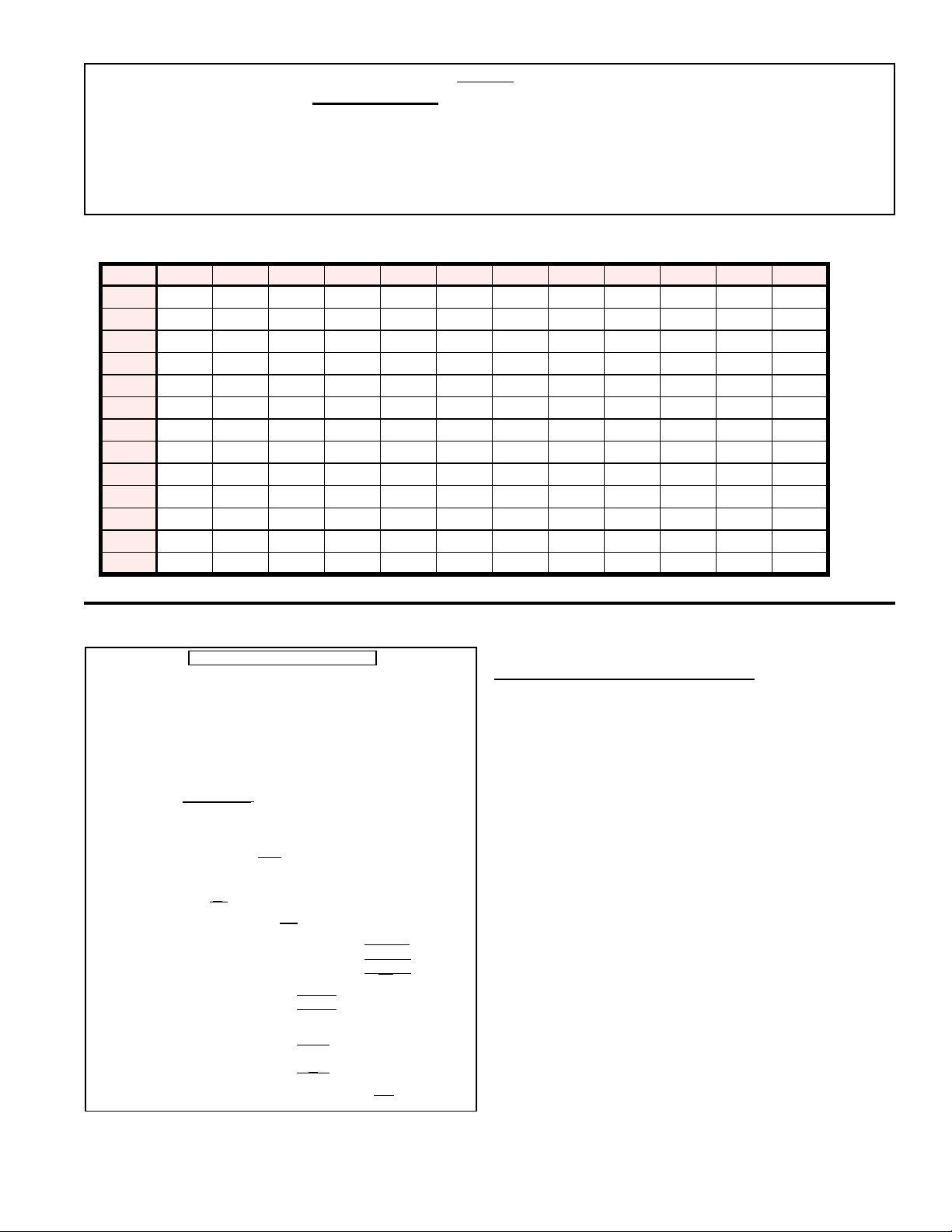
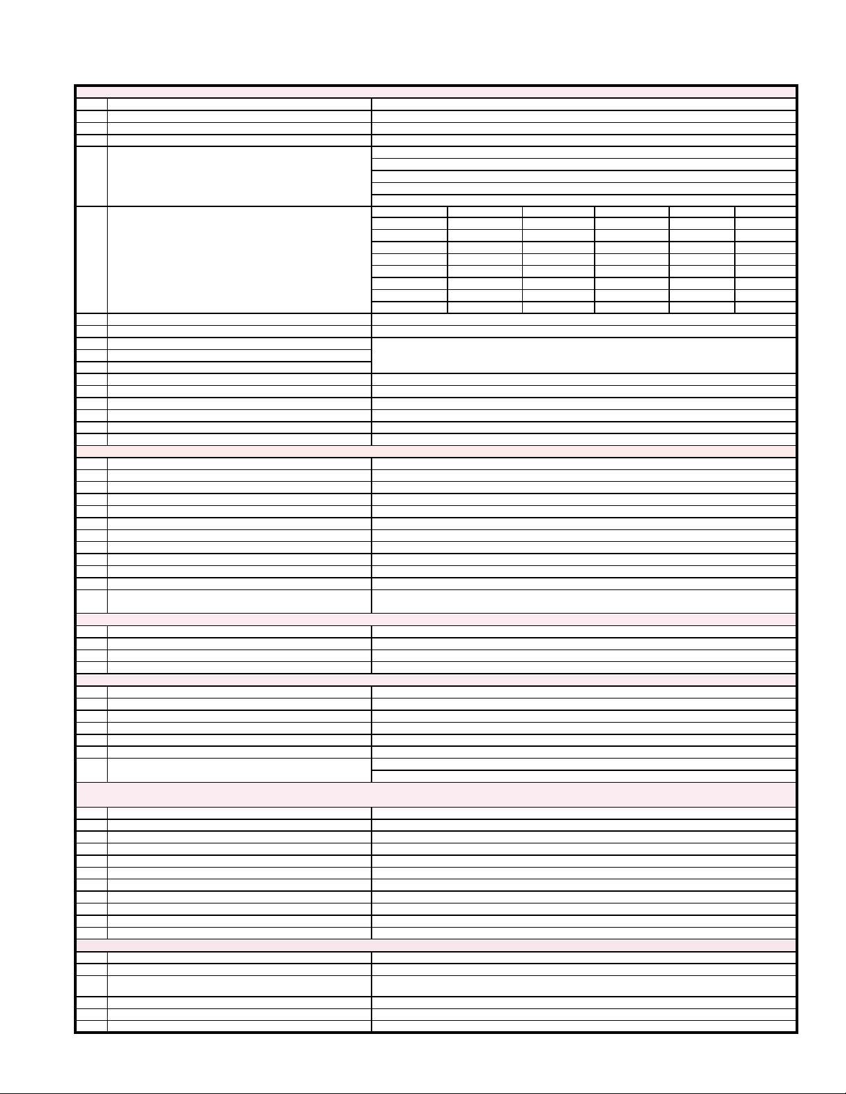
Cross-Reference Cabinet Size (1, 2 or 3) by Option Code
and Model/Model Size
Model YDHA YDMA YDSA
Nominal Cooling
Capacity (Tons)
Standard
Efciency
Gas Heat
Section
High
Efciency
Gas Heat
Section
Electric
Heat
Section
* Gas heat sections with dual furnaces.
Size 60 90 120 150 180 210 240 300 360 60 90 120 150 180 210 240 300 360 120 150 180 210
5 7.5 10 12.5 15 17.5 20 25 30 5 7.5 10 12.5 15 17.5 20 25 30 10 12.5 15 17.5
Opt
Code
H50 1 1 1 -- -- -- -- -- -- 1 -- -- -- -- -- -- -- -- -- -- -- -- H50
H75 1 1 1 1 2 -- -- -- -- 1 1 1 -- -- -- -- -- -- -- -- -- -- H75
H100 1 1 1 1 2 2 2 -- -- 1 1 1 1 -- -- -- -- -- 2 -- -- -- H100
H102* 1 1 1 1 2 2 2 -- -- 1 1 1 1 -- -- -- -- -- 2 -- -- -- H102*
H125* 1 1 1 1 2 2 2 -- -- 1 1 1 1 2 -- -- -- -- 2 2 -- -- H125*
H150* 1 1 1 1 2 2 2 -- -- 1 1 1 1 2 2 -- -- -- 2 2 3 -- H150*
H175* 1 1 1 1 2 2 2 -- -- 1 1 1 1 2 2 2 -- -- 2 2 3 3 H175*
H200 -- 1 1 1 2 2 2 3 3 1 1 1 1 2 2 2 3 3 2 2 3 3 H200
H202* -- 1 1 1 2 2 2 3 3 1 1 1 1 2 2 2 3 3 2 2 3 3 H202*
H300 -- 1 1 1 2 2 2 3 3 -- 1 1 1 2 2 2 3 3 2 2 3 3 H300
H400 -- -- 1 1 2 2 2 3 3 -- -- 1 1 2 2 2 3 3 2 2 3 3 H400
H402* -- -- 1 1 2 2 2 3 3 -- -- 1 1 2 2 2 3 3 2 2 3 3 H402*
H502* -- -- -- -- 2 2 2 3 3 -- -- -- -- 2 2 2 3 3 -- -- 3 3 H502*
H602* -- -- -- -- 2 2 2 3 3 -- -- -- -- 2 2 2 3 3 -- -- --- 3 H602*
H702* -- -- -- -H802* -- -- -- -- -- -- -- 3 3 -- -- -- -- -- -- -- 3 3 -- -- -- -- H802*
G150 1 1 1 1 2 2 2 -- -- 1 1 1 1 2 2 2 -- -- 2 2 3 3 G150
G225 1 1 1 1 2 2 2 3 3 1 1 1 1 2 2 2 3 3 2 2 3 3 G225
G300 -- 1 1 1 2 2 2 3 3 -- -- 1 1 2 2 2 3 3 2 2 3 3 G300
G302* -- 1 1 1 2 2 2 3 3 -- -- 1 1 2 2 2 3 3 2 2 3 3 G302*
G372* -- -- -- -- 2 2 2 3 3 -- -- -- -- 2 2 2 3 3 -- 2 3 3 G372*
G452* -- -- -- -- 2 2 2 3 3 -- -- -- -- 2 2 2 3 3 -- -- 3 3 G452*
G525* -- -- -- -- -- -- -- 3 3 -- -- -- -- -- -- -- 3 3 -- -- -- -- G525*
G602* -- -- -- -- -- -- -- 3 3 -- -- -- -- -- -- -- 3 3 -- -- -- -- G602*
E20 1 1 1 1 2 2 2 -- -- 1 1 1 1 2 2 2 -- -- 2 2 3 3 E20
E30 1 1 1 1 2 2 2 3 3 1 1 1 1 2 2 2 3 3 2 2 3 3 E30
E40 -- 1 1 1 2 2 2 3 3 -- 1 1 1 2 2 2 3 3 2 2 3 3 E40
E50 -- 1 1 1 2 2 2 3 3 -- 1 1 1 2 2 2 3 3 2 2 3 3 E50
E60 -- 1 1 1 2 2 2 3 3 -- 1 1 1 2 2 2 3 3 2 2 3 3 E60
E70 -- -- 1 1 2 2 2 3 3 -- -- 1 1 2 2 2 3 3 2 2 3 3 E70
E80 -- -- 1 1 2 2 2 3 3 -- -E90 -- -- 1 1 2 2 2 3 3 -- -- 1 1 2 2 2 3 3 2 2 3 3 E90
E120 -- -- -- -- 2 2 2 3 3 -- -- -- -- 2 2 2 3 3 -- -- 3 3 E120
-- -- -- 3 3 -- -- -- -- -- -- -- 3 3 -- -- -- -- H702*
1 1 2 2 2 3 3 2 2 3 3 E80
Opt
Code
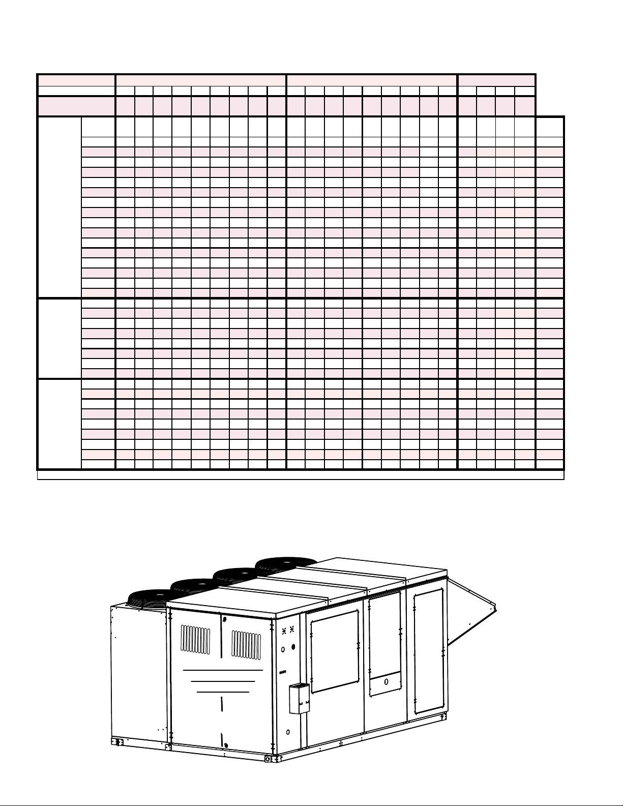
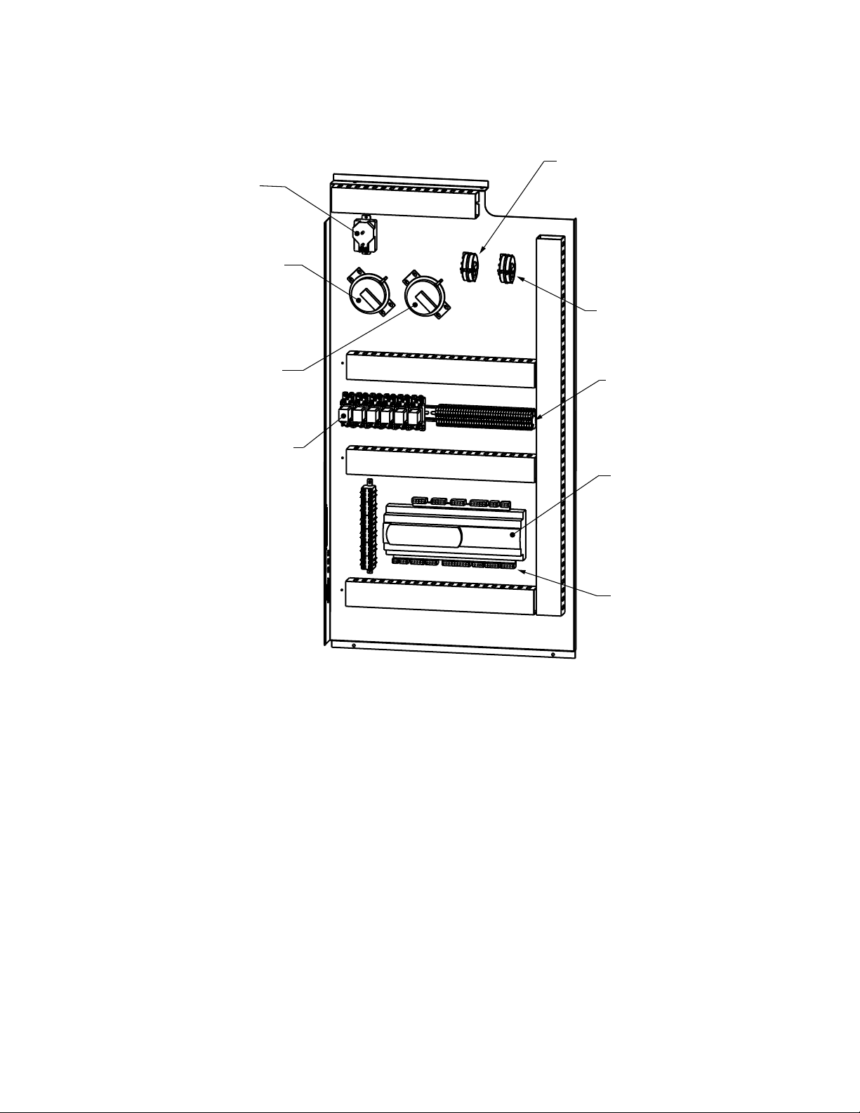
Electrical Compartment and Control Components
Locations of High and Low Voltage Control Components
See pages 5 thru 11 for P/N’s and illustrations.
Condenser Fans
Supply
Fan
Condenser
Section
Electric Heat Section
Form P-Y (6-16), PN 273651R23, Page 4
Electrical / Control
Compartments
(See below.)
Optional Gas or
Access
Inlet Air
Hood
Coil and
Filter Access
Damper Access
Optional Wheel Access
Page 5
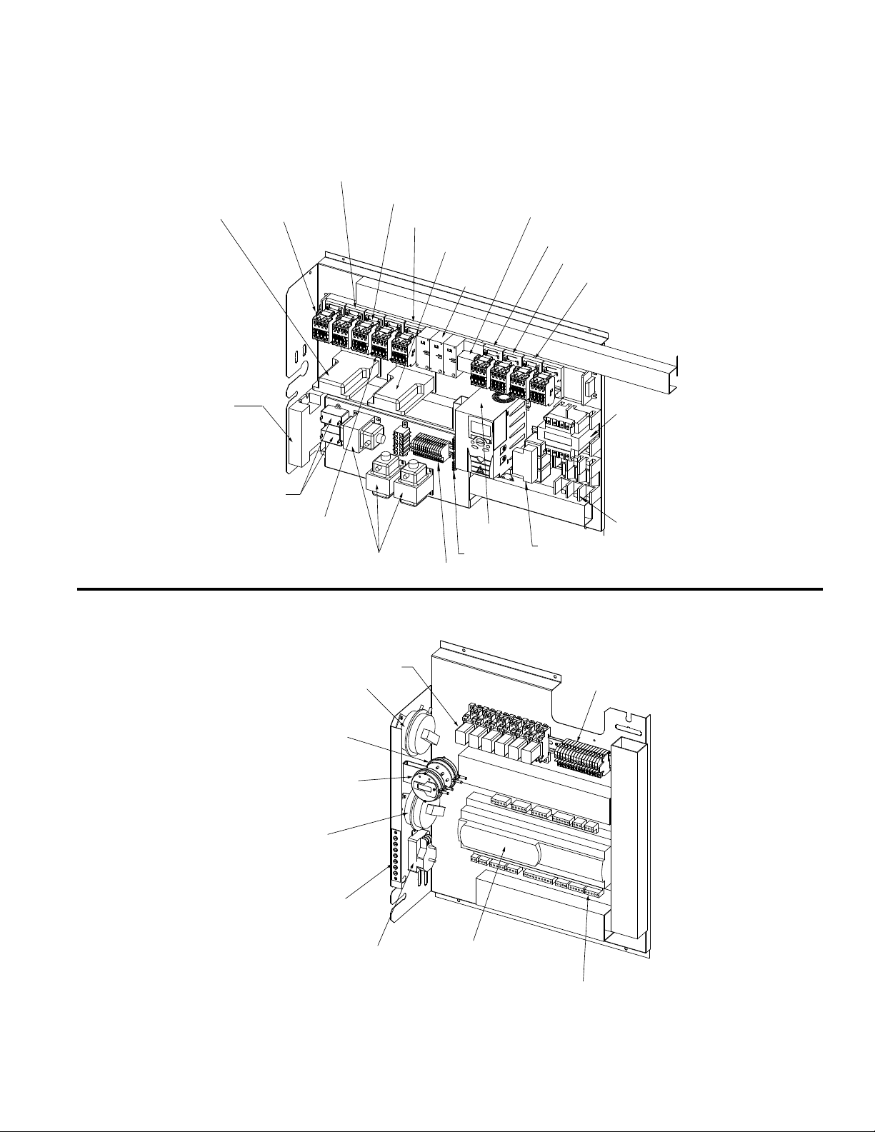
Electrical Compartment and Control Components (Cont’d)
Electrical Panels Cabinet Size 1A, Models YDHA size 60 & YDMA size 90
High Voltage Panel
(NOTE: Picture shown for illustration purposes - actual configuration to change with options purchased)
4 - Contactor
5 - Compressor
Controller (A)
9 / 10 - Low Ambient
Controller
(Cond Fan A)
4 - Contactor
(Compressor A)
4 - Contactor
(Compressor B)
4 - Contactor
(Compressor DH)
5 - Compressor
Controller (DH)
6 - Power
Feed
Terminals
1a - Phase Loss/Voltage
Monitor (not illustrated)
1b - Socket for 1a
4 - Contactor
(Power Exhaust)
4 - Contactor (ER Wheel)
4 - Contactor (ER Preheat)
3 - Transformer
11 - Capacitor
(Only used with standard
condenser Fan)
(NOTE: Picture shown for illustration purposes - actual configuration to change with options purchased)
21 - Unit Dirty Filter Switch
High Side - Red Tubing
Low Side - Clear Tubing
20 - Exhaust Fan Pressure Switch
High Side - Yellow Tubing
Low Side - Clear Tubing
18 - Supply Fan Pressure Switch
High Side - Blue Tubing
Low Side - Clear Tubing
22 - Energy Recovery Filter Switch
High Side - Green Tubing
Low Side - Clear Tubing
4 - Contactor
(Cond Fan B)
23 - Terminal Strip
7 - VFD
3 - Transformer
25 - Terminal Blocks
2 - Ground Bar
Low Voltage Panel
19 - Relay
13 - Fuses
8 - Line Reactor
25 - Terminal Blocks
24 - Pressure Sensor
Transducer
14 - Carel
Controller
16 - BacNet Card (BHB8)
17 - Lon Card (BHB7)
(Not Illustrated)
15 - Plugs for Code 14
Form P-Y (6-16), PN 273651R23, Page 5
Page 6
High Voltage Panel
Low Voltage Panel
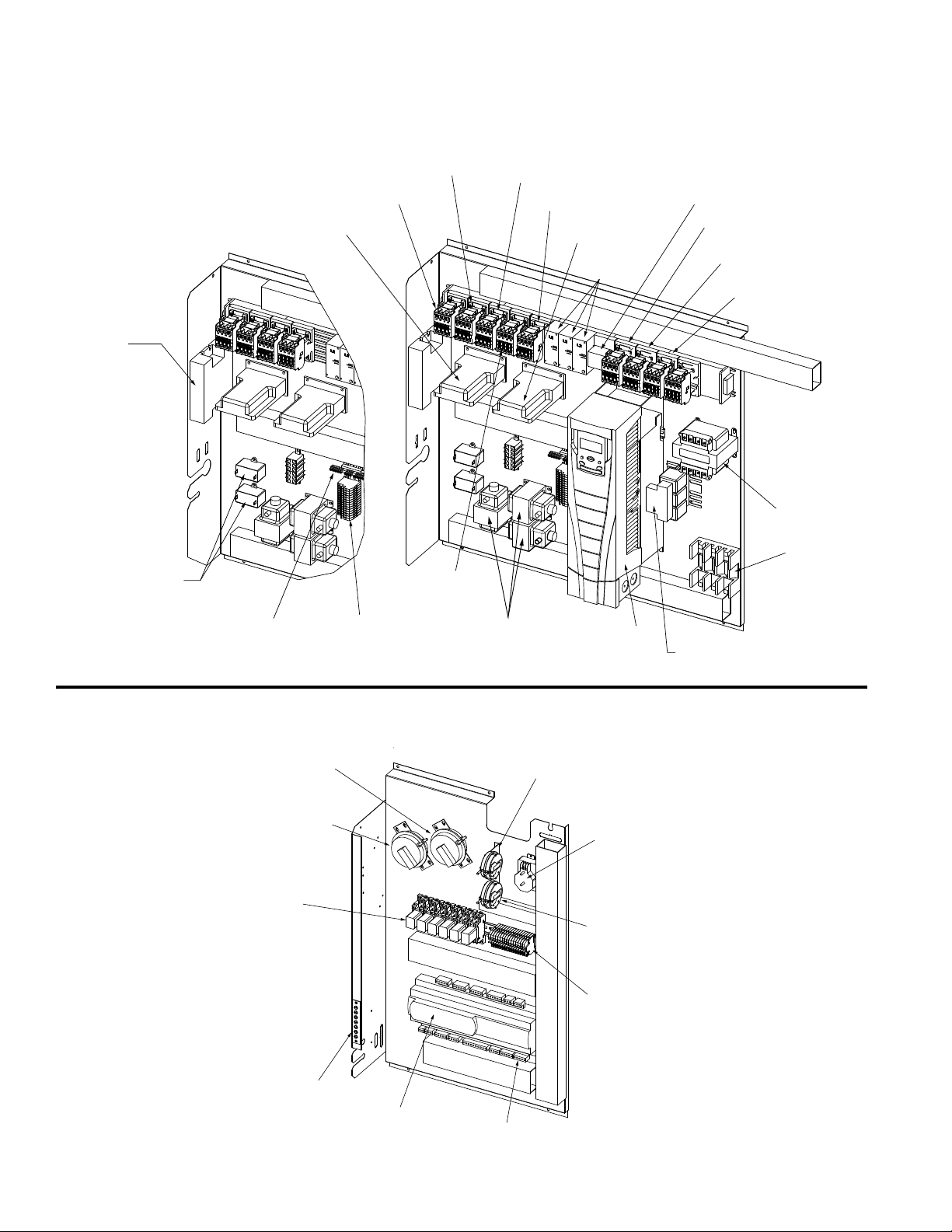
Electrical Compartment and Control Components (Cont’d)
Electrical Panels Cabinet Size 1B, Models YDHA sizes 90, 120, 150 & YDMA sizes 120 & 150
9 / 10 - Low Ambient
Controller
11 - Capacitor
(Note: only used with
standard condenser fan)
(NOTE: Picture shown for illustration purposes - actual configuration to change with options purchased)
4 - Contactor
(Compressor A)
5 - Compressor Controller
(Circuit A)
2 - Ground Bar
25 - Terminal
Blocks
4 - Contactor
(Cond Fan A)
4 - Contactor
(Cond Fan B)
4 - Contactor
(Compressor B)
4 - Contactor
(Compressor DH)
3 - Transformer
5 - Compressor
Controller (DH)
6 - Power Feed
Terminals
7 - VFD
1a - Phase
Loss/Voltage Monitor
(not illustrated)
1b - Socket for 1a
4 - Contactor
(Power Exhaust)
8 - Line Reactor
4 - Contactor
(ER Wheel)
4 - Contactor
(ER Preheat)
3 - Transformer
13 - Fuses
(NOTE: Picture shown for illustration purposes - actual configuration to change with options purchased)
21 - Unit Dirty Filter Switch
High Side - Red Tubing
Low Side - Clear Tubing
22 - Energy Recovery Filter Switch
High Side - Green Tubing
Low Side - Clear Tubing
19 - Relay
23 - Terminal Strip
16 - BacNet Card (BHB8)
17 - Lon Card (BHB7)
(Not Illustrated)
14 - Carel
Controller
18 - Supply Fan Pressure Switch
High Side - Blue Tubing
Low Side - Clear Tubing
15 - Plugs for Code 14
24 - Pressure Sensor
Transducer
20 - Exhaust Fan Pressure Switch
High Side - Yellow Tubing
Low Side - Clear Tubing
25 - Terminal Blocks
Form P-Y (6-16), PN 273651R23, Page 6
Page 7
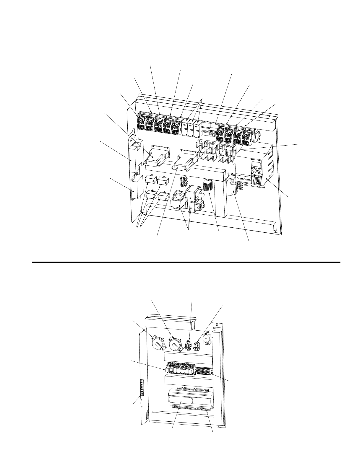
High Voltage Panel
Electrical Panels Cabinet Size 2, Models YDHA & YDMA sizes 180, 210 & 240 and Model YDSA Sizes 120 & 150
(NOTE: Picture shown for illustration purposes - actual configuration to change with options purchased)
4 - Contactor
(Compressor A)
5 - Compressor Controller
(Circuit A)
9 - Low Ambient Controller
for ECM Condenser Fan
10 - Low Ambient Controller
for Standard Condenser Fan
4 - Contactor
(Cond Fan A)
4 - Contactor
(Compressor B)
1
2
4 - Contactor
(Cond Fan B)
4 - Contactor
(Compressor DH)
6 - Power Feed
Terminals
1a - Phase
Loss/Voltage Monitor
(not illustrated)
1b - Socket for 1a
4 - Contactor
(Power Exhaust)
4 - Contactor
(ER Wheel)
4 - Contactor
(ER Preheat)
26 - Fuses
3
4
11 - Capacitors
5 - Compressor
Controller (DH)
3 - Transformers
25 - Terminal Blocks
(NOTE: Picture shown for illustration purposes - actual configuration to change with options purchased)
22 - Energy Recovery Filter Switch
High Side - Green Tubing
Low Side - Clear Tubing
Low Voltage Panel
21 - Unit Dirty Filter Switch
High Side - Red Tubing
Low Side - Clear Tubing
19 - Relay
20 - Exhaust Fan Pressure Switch
High Side - Yellow Tubing
Low Side - Clear Tubing
18 - Supply Fan Pressure Switch
High Side - Blue Tubing
Low Side - Clear Tubing
24 - Pressure Sensor
Transducer
8 - Line Reactor
7 - VFD
2 - Ground Bar
(Not Illustrated)
23 - Terminal Strip
14 - Carel Controller
16 - BacNet Card (BHB8)
17 - Lon Card (BHB7)
(Not Illustrated)
25 - Terminal Blocks
15 - Plugs for Code 14
Form P-Y (6-16), PN 273651R23, Page 7
Page 8
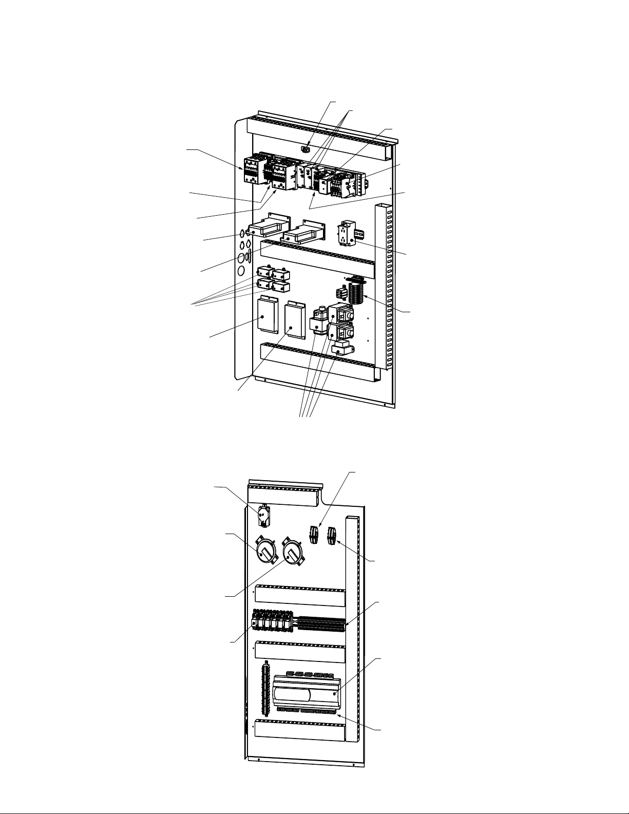
Electrical Compartment and Control Components (Cont’d)
27 - Terminal Blocks
16 - Carel Controller
18 - BacNet Card (BHB8)
19 - Lon Card (BHB7)
(Not Illustrated)
17 - Plugs for Code 16
21 - Relay
24 - Energy Recovery Filter Switch
High Side - Green Tubing
Low Side - Clear Tubing
23 -Unit Dirty Filter Switch
High Side - Red Tubing
Low Side - Clear Tubing
20 - Supply Fan Pressure Switch
High Side - Blue Tubing
Low Side - Clear Tubing
22 - Exhaust Fan Pressure Switch
High Side - Yellow Tubing
Low Side - Clear Tubing
26 - Pressure Sensor
Transducer
Low Voltage Panel
(NOTE: Picture shown for illustration purposes - actual configuration to change with options purchased)
Electrical Panels Cabinet Size 3, Models YDHA & YDMA sizes 300 & 360 and Model YDSA Sizes 180 & 210
(NOTE: Picture shown for illustration purpose - actual configuration to change with options purchased)
4 - Contactor
(Compressor A)
4 - Contactor
(Condenser A)
4 - Contactor
(Compressor DH)
5 - Compressor Controller
(Circuit A)
5 - Compressor
Controller (DH)
13 - Capacitors
(Note: only used with standard condenser fan)
11 - Low Ambiant
Controller
High Voltage Panel #1
14 - Grounding Lug
6 - Power Feed
Terminals
1
2
3
4
1a - Phase Loss / Voltage
Monitor
4 - Contactor
(Compressor B)
4 - Contactor
(Condenser B)
50 - Convenience
Outlet - 125v
27 - Terminal Blocks
12 - Low Ambiant
Controller
3 - Transformer
Form P-Y (6-16), PN 273651R23, Page 8
Page 9
Electrical Panels Cabinet Size 3, Models YDHA & YDMA sizes 300 & 360 and Model YDSA Sizes 180 & 210
(cont’d)
Low Voltage Panel
(NOTE: Picture shown for illustration purposes - actual configuration to change with options purchased)
26 - Pressure Sensor
Transducer
24 - Energy Recovery Filter Switch
High Side - Green Tubing
Low Side - Clear Tubing
23 -Unit Dirty Filter Switch
High Side - Red Tubing
Low Side - Clear Tubing
21 - Relay
22 - Exhaust Fan Pressure Switch
High Side - Yellow Tubing
Low Side - Clear Tubing
20 - Supply Fan Pressure Switch
High Side - Blue Tubing
Low Side - Clear Tubing
27 - Terminal Blocks
16 - Carel Controller
18 - BacNet Card (BHB8)
19 - Lon Card (BHB7)
(Not Illustrated)
17 - Plugs for Code 16
Form P-Y (6-16), PN 273651R23, Page 9
Page 10

Gas Heat Section Control Panel
Electrical Compartment and Control Components (Cont’d)
Electrical Panel Cabinet Size 1, 2 & 3 - All Models
(NOTE: Picture shown for illustration purposes - actual configuration to change with options purchased)
Electric Heat Control Panel
27 - Contactors
28 - SCR Controller
26 - Fuses
29 - Distribution Block
(NOTE: Picture shown for illustration purposes - actual configuraton to change with options purchased)
31 - Low Speed Venter Switch
(Options AG73 & AG74)
30 - High Speed Venter
Combustion Air Switch
32 - Blocked Condensate
Switch for High Efficiency,
Condensing Furnace
Controls for all Gas Heat Sections
Additonal Controls for Dual
Gas Heat Sections
30 - High Speed Venter
Combustion Air Switch
32 - Blocked Condensate
Switch for High Efficiency,
Condensing Furnace
36 - 75VA Transformer
25 - Terminal Blocks
33 - Venter Motor Speed Controller
(Options AG73 & AG74)
34 - Relay
35 - DSI Control Module for
Single Heat Section or
Right (first) Furnace in
a Dual Heat Section
34 - Relay
35 - DSI Control Module for
the Left (second) Furnace
in a Dual Heat Section
Form P-Y (6-16), PN 273651R23, Page 10
Page 11
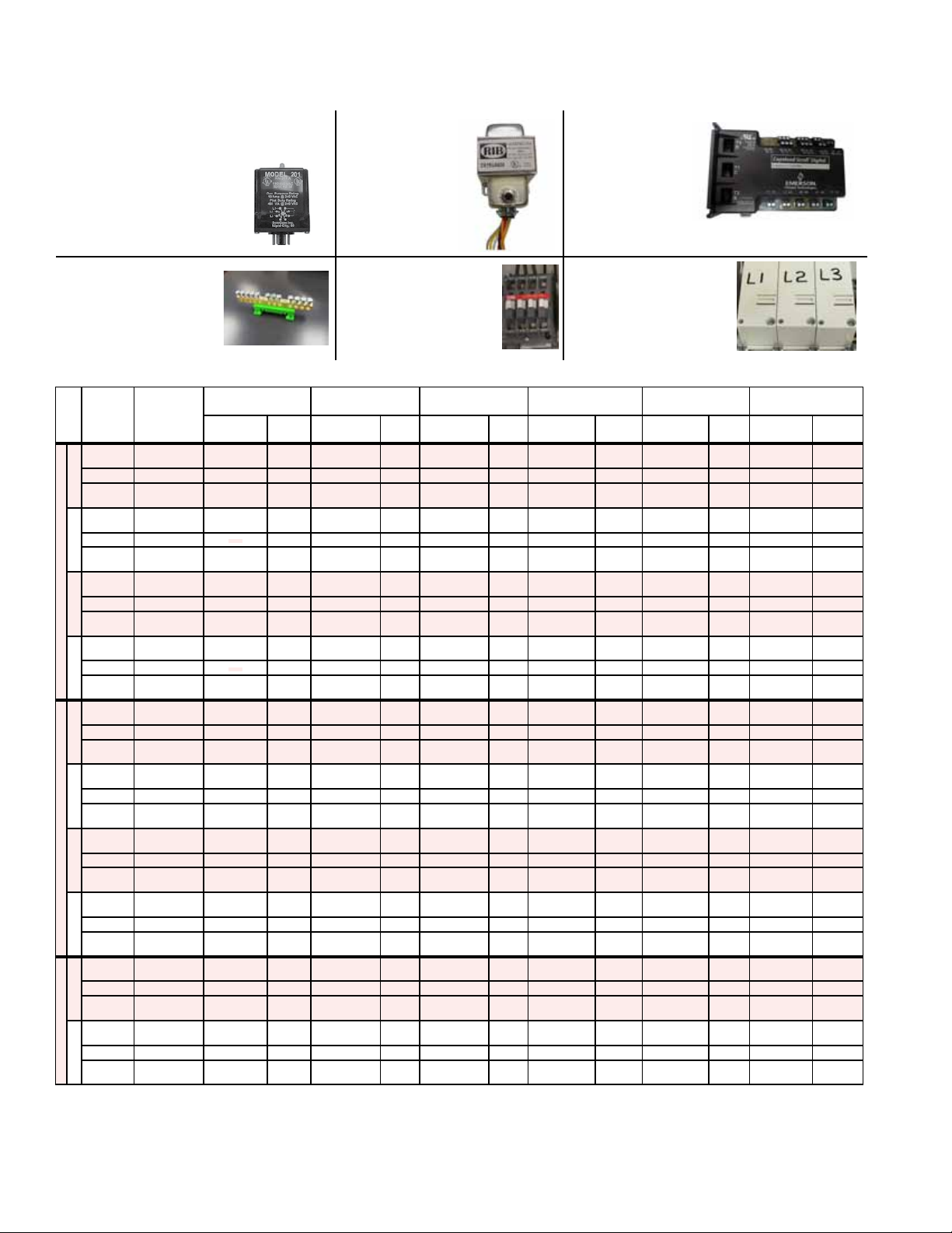
Electrical Components - Replacement P/N’s
For Component Location: Cabinet 1A & 1B, see pages 5, 6 & 10; Cabinet 2, see pages 7 & 10, Cabinet 3, see
pages 8, 9 & 10. For an Illustration of most parts, see pages 12, 16 & 17.
Electrical Components - Unit High Voltage Panel
Code Description P/N
1A Phase Loss/Voltage Monitor (Opt PL4) 208/230/460V (AK5/6/7) - 176826; 575V (AK8) - 258881
1B Socket for Code 1A Monitors 194168
2 Grounding bar, 12 Output 273792
3 Transformers
4 Contactor (24v coil)
5 Digital Controller - for compressors 266067
6 Power Feed Terminals 271834 L-1; 271833 L-2; 271832 L-3
7 VFD
9 Supply Fan
10 Overload Relay See table on page 13
11 Low Ambient Controller for ECM Condenser Fan (Opt CUF4) Control P/N 272460; Sensor P/N 272461
12 Low Ambient Controller for Standard Condenser Fan (Opt CUF3) Control P/N 261041; Sensor P/N 261042
13 Capacitor 207448
14 Grounding Lug 179196
15 Fuses for wheel preheat (opt PH-__) 207617, (Opt AK3) & 207615, 207617(Opt AK5 & AK6)
Electrical Components - Unit Low Voltage Panel
16 Carel Digital Controller with Programmed Software 235689
17 Carel Plugs 272630
18 BacNet DDC Communication Bus “programmed” (Opt BHB8) 272633 (Opt BHB8 w/D19) or 1006079 (Opt BHB8 w/D21)
19 LON DDC Communication Bus “programmed” (Opt BHB7) 284991N (Opt BHB7 w/D19) or 284992 (Opt BHB7 w/D21)
20 Supply Fan Pressure Switch 234712
21 Relays (2 Pole & 3 Pole) 2 Pole 211411, 24v (Base, P/N 211415) & 3 Pole 211799, 24v (Base, P/N 211800)
22 Exhaust Fan Pressure Switch 234712
23 Unit Dirty Filter Switch 105507
24 Energy Recovery Filter Switch 105507
25 Terminal Strip 164545
26 Pressure Sensor Transducer 234818 (Opt VFC3, EFC3); 234819 (Opt VFC4, EFC4, GF5)
Terminal Blocks (Note: used in low voltage, high voltage and
27
gas heat control panels)
Electrical Components - Electric Heat Section Panel
28 Fuses 207615 (30A/250V); 207617 (60A/250V); 207627 (45A/600V)
29 Contactors For P/N’s, see Table, pages 37 thru 39 & 45
30 SCR Controller 234057 (208/230/3/60); 220688 (460/575/3/60)
31 Distribution Block 223495
Electrical Components - Gas Heat Section Panel
32 High Venter (Combustion Air Switch - High Pressure) For P/N’s, see illustration & Table, pages 18 & 19
33 Low Speed Venter (Combustion Air Switch - Low Pressure) For P/N’s, see illustration & Table, pages 18 & 19
34 Blocked Condensate Switch (High Efciency Furnace) 234712
35 Venter Motor Speed Control (Opts AK3, AK5, AK6, AK7, AK8) Ref picture and option sheet for specic board w/ correct switch settings on page 20
36 Ribme Relay Board 234656
37 DSI Control Module 272626
38 Transformers
Various Sensors for Monitoring and Reporting to the Digital Controller - Depending on the application, sensors may be standard or part of controls
options Opt BE__, supply fan control options Opt VFC__, or inlet damper control options Opt GF__.
39 Outside Air Humidity Sensor 222754 (in the outside air inlet)
40 Discharge Air Sensor & Box, 8” probe 222753 (in the discharge ductwork)
41 Space Temperature Sensor (Opts CL23, CL33 & CL78) 257338 (Opt CL23); 221038 (Opt CL33); 272631 (Opt CL78)
42 Return Air Temperature Sensor & Box, 8” probe 222753 (in the return air inlet)
43 Building CO
44 Photoelectric Smoke Detector (in BE17) 259076 (BE17 includes; smoke detector, P/N 159553 & sampling tube, P/N 259069)
45 Duct Static Pressure (in Option VFC3) Transducer, P/N 234818; Sensor Port, P/N 234821
46 Building Static Pressure (in Option VFC4 & GF5) Transducer, P/N 234819 (installed in the building)
47 Dirty Filter Pressure Switch (in Option BE18 & BE28) 105507 (measures pressure drop)
48 Averaging Temp Sensor (18”) 271993 (Cabinet Size 1)
49 Averaging Temp Sensor (36”) 271994 (Cabinet Sizes 2 & 3)
Sensor (in Opts GF8 & BE15) 256975 (BE15 includes CO2 sensor; P/N 234820)
2
Other Electrical Components
50 Convenience Outlet 125v 272900
51 Ductstat (Return or Discharge) or Firestat (in Opt BD5) 42782
52 Remote Display for Digital Controller (Opts RB5, RB6)
53 Non-fusible Disconnect Switch (in Option BA6_) See Table on page 20
54 Disconnect Switch (Option CP_) See Table on page 20
55 Display for Digital Controller (Option RB4) 258452
11100, 0.5 kva, 480-230/120 (Fuse 201803, 3 amp), Cutler Hammer S20N11S51
11217, 0.75 kva, 240/480-120/240V, Cutler Hammer S20N11S76
for Condenser Fan for Compressors for Supply Air Fan for Power Exhaust for Preheater for ER Wheel
271999,12A 271836, 9A 271836, 9A 271836, 9A 272001, 26A 271836, 9A
272489 (Gray), 272490 (Orange), 272791 (Blue), 272492 (Black), 272493 (Red), 272494 (Ivory),
208989, 75 va, 120/208/240/480-24V, includes circuit breaker, Functional Devices TR75VA005
260436 (Opt RB5 Includes Display, P/N 260178, 6-pin Connection Cable P/N 260175 & Cable Splitter & Signal
Booster Module, P/N 260735); 272407 (Opt RB6 includes Remote Hand Held Display, P/N 260178)
271999,12A 271999,12A 271999, 12A 272416, 40A
272000,16A 272000, 16A
272001, 26A
272002, 30A
272416, 40A
272417, 50A
272418, 75A
258912, 75 va 460/575-24V, Hartland Controls HCT-130J2K02199
210862, 200 va, 460/575-230V, (ERM)
284219, 6.0 kva, 600/480V
284237, 9.0 kva, 600/480V
See tables on pages 12 thru 158 Line Reactor
272495 (Yellow), 272496 (Green) & 272497 (End Section)
Form P-Y (6-16), PN 273651R23, Page 11
Page 12
Electrical Components - Replacement P/N’s (Cont’d)
For Component Location: Cabinet 1A & 1B, see pages 5, 6 & 10; Cabinet 2, see pages 7 & 10, Cabinet 3, see
pages 8, 9 & 10. For an Illustration of most parts, see pages 12, 16 & 17.
Code 1A - Phase Loss/Voltage
Monitor, 208/230/460V - P/N 176826;
575V - P/N 258881
Code 1B - Socket for
Code 1A monitors -
P/N
194168
Codes 3 & 38 Transformers
- P/N’s Vary
Ref Electrical
Components
Chart, page 11
Code 5 -
Digital
Controller for
Compressors,
P/N 266067
Code 2 - Grounding
Bar - P/N 273792
Code 4 - Contactor
- P/N’s Vary
Ref Electrical
Components Chart,
page 11
Code 6 - Power Feed
Terminals - P/N’s
Vary Ref Electrical
Components List,
page 11
Unit Supply Fan Option A10 Components (Codes 7, 8 & 9)- See component photos on page 16
Mod
&
Code No Description
Size
7 VFD --- ---
8 Line Reactor --- ---
120
9 Supply Fan --- ---
7 VFD --- ---
8 Line Reactor --- ---
150
9 Supply Fan --- ---
YDSA
7 VFD --- ---
8 Line Reactor --- ---
180
9 Supply Fan --- ---
7 VFD --- ---
8 Line Reactor --- ---
210
9 Supply Fan --- ---
7 VFD --- ---
8 Line Reactor --- ---
210
9 Supply Fan --- ---
7 VFD --- ---
8 Line Reactor --- ---
240
9 Supply Fan --- ---
YDHA
7 VFD --- ---
8 Line Reactor --- ---
300
9 Supply Fan ---
7 VFD --- ---
8 Line Reactor --- ---
360
9 Supply Fan --- ---
7 VFD --- ---
8 Line Reactor --- ---
210
9 Supply Fan
YDMA
7 VFD --- ---
8 Line Reactor --- ---
240
9 Supply Fan
AK3 - 230/1/60 AK5 - 208/3/60 AK6 - 230/3/60 AK7 - 460/3/60 AK8 - 575/3/60 AK12 - 400/3/50
Model No P/N Model No P/N Model No. P/N
ACS550-U1-
024A-2
--- --- --- --- --- --- --- --- --- ---
ER50C-4DM.
G7.1R
ACS550-U1-
024A-2
--- --- --- --- --- --- --- --- --- ---
ER50C-4DM.
G7.1R
ACS550-U1-
024A-2
--- --- --- --- --- --- --- --- --- ---
ER50C-4DM.
G7.1R
ACS550-U1-
024A-2
--- --- --- --- --- --- --- --- --- ---
ER50C-4DM.
G7.1R
ACS550-U1-
024A-2
--- --- --- --- KDRA4L 221588 --- --- KDRA4L 221588
ER50C-4DM.
G7.1R
ACS550-U1-
024A-2
--- --- --- --- KDRA4L 221588 --- --- KDRA4L 221588
ER50C-4DM.
G7.1R
ACS550-U1-
024A-2
--- --- --- --- --- --- --- --- --- ---
ER50C-4DM.
G7.1R
ACS550-U1-
024A-2
--- --- --- --- --- --- --- --- --- ---
ER50C-4DM.
G7.1R
ACS550-U1-
024A-2
--- --- --- --- KDRA4L 221588 --- --- KDRA4L 221588
ER50C-4DM.
G7.1R
ACS550-U1-
024A-2
--- --- --- --- KDRA4L 221588 --- --- KDRA4L 221588
ER50C-4DM.
G7.1R
221621
235687
221621
235687
221621
235687
221621
235687
221621
235687
221621
235687
221621
235687
221621
235687
221621
235687
221621
235687
ACS550-U1-
024A-2
ER50C-4DM.
G7.1R
ACS550-U1-
024A-2
ER50C-4DM.
G7.1R
ACS550-U1-
024A-2
ER50C-4DM.
G7.1R
ACS550-U1-
024A-2
ER50C-4DM.
G7.1R
ACS550-U1-
024A-2
ER50C-4DM.
G7.1R
ACS550-U1-
024A-2
ER50C-4DM.
G7.1R
ACS550-U1-
024A-2
ER50C-4DM.
G7.1R
ACS550-U1-
024A-2
ER50C-4DM.
G7.1R
ACS550-U1-
024A-2
ER50C-4DM.
G7.1R
ACS550-U1-
024A-2
ER50C-4DM.
G7.1R
221621
235687
221621
235687
221621
235687
221621
235687
221621
235687
221621
235687
221621
235687
221621
235687
221621
235687
221621
235687
Model/Part
No.
ACS550-U1-
012A-4
ER50C-4DM.
G7.1R
ACS550-U1-
012A-4
ER50C-4DM.
G7.1R
ACS550-U1-
012A-4
ER50C-4DM.
G7.1R
ACS550-U1-
012A-4
ER50C-4DM.
G7.1R
ACS355-03U-
12A5-4+J404
ER50C-4DM.
G7.1R
ACS355-03U-
12A5-4+J404
ER50C-4DM.
G7.1R
ACS550-U1-
012A-4
ER50C-4DM.
G7.1R
ACS550-U1-
012A-4
ER50C-4DM.
G7.1R
ACS355-03U-
12A5-4+J404
ER50C-4DM.
G7.1R
ACS355-03U-
12A5-4+J404
ER50C-4DM.
G7.1R
P/N
284560
235687
284560
235687
284560
235687
284560
235687
221619
235687
221619
235687
284560
235687
284560
235687
221619
235687
221619
235687
Model/Part
No.
ACS550-U1-
09A0-6
ER50C-4DM.
G7.1R
ACS550-U1-
09A0-6
ER50C-4DM.
G7.1R
ACS550-U1-
09A0-6
ER50C-4DM.
G7.1R
ACS550-U1-
09A0-6
ER50C-4DM.
G7.1R
ACS550-U1-
09A0-6
ER50C-4DM.
G7.1R
ACS550-U1-
09A0-6
ER50C-4DM.
G7.1R
ACS550-U1-
09A0-6
ER50C-4DM.
G7.1R
ACS550-U1-
09A0-6
ER50C-4DM.
G7.1R
ACS550-U1-
09A0-6
ER50C-4DM.
G7.1R
ACS550-U1-
09A0-6
ER50C-4DM.
G7.1R
P/N
221858
235688
221858
235688
221858
235688
221858
235688
221858
235688
221858
235688
221858
235688
221858
235688
221858
235688
221858
235688
Model/Part
No.
ACS550-U1-
012A-4
ER50C-4DM.
G7.1R
ACS550-U1-
012A-4
ER50C-4DM.
G7.1R
ACS550-U1-
012A-4
ER50C-4DM.
G7.1R
ACS550-U1-
012A-4
ER50C-4DM.
G7.1R
ACS355-03U-
12A5-4+J404
ER50C-4DM.
G7.1R
ACS355-03U-
12A5-4+J404
ER50C-4DM.
G7.1R
ACS550-U1-
012A-4
ER50C-4DM.
G7.1R
ACS550-U1-
012A-4
ER50C-4DM.
G7.1R
ACS355-03U-
12A5-4+J404
ER50C-4DM.
G7.1R
ACS355-03U-
12A5-4+J404
ER50C-4DM.
G7.1R
P/N
284560
235687
284560
235687
284560
235687
284560
235687
221619
235687
221619
235687
284560
235687
284560
235687
221619
235687
221619
235687
Form P-Y (6-16), PN 273651R23, Page 12
Page 13

Unit Supply Fan Option A10 Components (Codes 7, 8 & 9) Cont’d - See component photos on page 16
Mod
&
Code No Description
Size
7 VFD --- ---
8 Line Reactor --- ---
300
9 Supply Fan ---
YDMA
7 VFD --- ---
8 Line Reactor --- ---
360
9 Supply Fan ---
AK3 - 230/1/60 AK5 - 208/3/60 AK6 - 230/3/60 AK7 - 460/3/60 AK8 - 575/3/60 AK12 - 400/3/50
Model No P/N Model No P/N Model No. P/N
ACS550-U1-
024A-2
--- --- --- --- --- --- --- --- --- ---
ER50C-4DM.
G7.1R
ACS550-U1-
024A-2
--- --- --- --- --- --- --- --- --- ---
ER50C-4DM.
G7.1R
221621
235687
221621
235687
ACS550-U1-
024A-2
ER50C-4DM.
G7.1R
ACS550-U1-
024A-2
ER50C-4DM.
G7.1R
221621
235687
221621
235687
Model/Part
No.
ACS550-U1-
012A-4
ER50C-4DM.
G7.1R
ACS550-U1-
012A-4
ER50C-4DM.
G7.1R
P/N
284560
235687
284560
235687
Model/Part
No.
ACS550-U1-
09A0-6
ER50C-4DM.
G7.1R
ACS550-U1-
09A0-6
ER50C-4DM.
G7.1R
P/N
221858
235688
221858
235688
Unit Supply Fan Option A10E Components (Codes 4, 9 & 10)- See component photos on page 16
Mod
&
Code No Description
Size
Supply Fan
4
Contactor
9 Supply Fan --- ---
60
Overload
10
4
9 Supply Fan --- ---
90
10
4
9 Supply Fan --- ---
120
YDHA
10
4
9 Supply Fan --- ---
150
10
4
9 Supply Fan --- ---
180
10
4
9 Supply Fan --- ---
60
10
4
9 Supply Fan --- ---
90
10
4
9 Supply Fan --- ---
120
YDMA
10
4
9 Supply Fan --- ---
150
10
4
9 Supply Fan --- ---
180
10
Relay
Supply Fan
Contactor
Overload
Relay
Supply Fan
Contactor
Overload
Relay
Supply Fan
Contactor
Overload
Relay
Supply Fan
Contactor
Overload
Relay
Supply Fan
Contactor
Overload
Relay
Supply Fan
Contactor
Overload
Relay
Supply Fan
Contactor
Overload
Relay
Supply Fan
Contactor
Overload
Relay
Supply Fan
Contactor
Overload
Relay
AK3 - 230/1/60 AK5 - 208/3/60 AK6 - 230/3/60 AK7 - 460/3/60 AK8 - 575/3/60 AK12 - 400/3/50
Model No P/N Model No P/N Model No. P/N
--- ---
AF09-30-10-41 271836 AF09-30-10-41 271836 AF09-30-10-41 271836
ER31C-ZID.
DC.1R
235653
ER31C-ZID.
DC.1R
235653
Model/Part
No.
ER31C-ZID.
DC.1R
P/N
235656
Model/Part
No.
--- ---
--- ---
P/N Model/Part No. P/N
AF09-30-10-41 271836
ER31C-ZID.
NOT REQUIRED - NOTE: This Overload Was Included on Some Early Production Units
--- ---
AF12-30-10-41 271999 AF12-30-10-41 271999 AF09-30-10-41 271836
ER45C-ZID.
GG.1R
235655
ER45C-ZID.
GG.1R
235655
ER45C-ZID.
GG.1R
235658
--- ---
--- ---
AF09-30-10-41 271836
ER45C-ZID.
NOT REQUIRED - NOTE: This Overload Was Included on Some Early Production Units
--- ---
AF12-30-10-41 271999 AF12-30-10-41 271999 AF09-30-10-41 271836
ER45C-ZID.
GG.1R
235655
ER45C-ZID.
GG.1R
235655
ER45C-ZID.
GG.1R
235658
--- ---
--- ---
AF09-30-10-41 271836
ER45C-ZID.
NOT REQUIRED - NOTE: This Overload Was Included on Some Early Production Units
--- ---
AF12-30-10-41 271999 AF12-30-10-41 271999 AF09-30-10-41 271836
ER45C-ZID.
GG.1R
235655
ER45C-ZID.
GG.1R
235655
ER45C-ZID.
GG.1R
235658
--- ---
--- ---
AF09-30-10-41 271836
ER45C-ZID.
NOT REQUIRED - NOTE: This Overload Was Included on Some Early Production Units
--- ---
AF12-30-10-41 271999 AF12-30-10-41 271999 AF09-30-10-41 271836
ER45C-ZID.
GG.1R
235655
ER45C-ZID.
GG.1R
235655
ER45C-ZID.
GG.1R
235658
--- ---
--- ---
AF09-30-10-41 271836
ER45C-ZID.
NOT REQUIRED - NOTE: This Overload Was Included on Some Early Production Units
--- ---
AF09-30-10-41 271836 AF09-30-10-41 271836 AF09-30-10-41 271836
ER31C-ZID.
DC.1R
235653
ER31C-ZID.
DC.1R
235653
ER31C-ZID.
DC.1R
235656
--- ---
--- ---
AF09-30-10-41 271836
ER31C-ZID.
NOT REQUIRED - NOTE: This Overload Was Included on Some Early Production Units
--- ---
AF09-30-10-41 271836 AF09-30-10-41 271836 AF09-30-10-41 271836
ER31C-ZID.
DC.1R
235653
ER31C-ZID.
DC.1R
235653
ER31C-ZID.
DC.1R
235656
--- ---
--- ---
AF09-30-10-41 271836
ER31C-ZID.
NOT REQUIRED - NOTE: This Overload Was Included on Some Early Production Units
--- ---
AF12-30-10-41 271999 AF12-30-10-41 271999 AF09-30-10-41 271836
ER45C-ZID.
GG.1R
235655
ER45C-ZID.
GG.1R
235655
ER45C-ZID.
GG.1R
235658
--- ---
--- ---
AF09-30-10-41 271836
ER45C-ZID.
NOT REQUIRED - NOTE: This Overload Was Included on Some Early Production Units
--- ---
AF12-30-10-41 271999 AF12-30-10-41 271999 AF09-30-10-41 271836
ER45C-ZID.
GG.1R
235655
ER45C-ZID.
GG.1R
235655
ER45C-ZID.
GG.1R
235658
--- ---
--- ---
AF09-30-10-41 271836
ER45C-ZID.
NOT REQUIRED - NOTE: This Overload Was Included on Some Early Production Units
--- ---
AF12-30-10-41 271999 AF12-30-10-41 271999 AF09-30-10-41 271836
ER45C-ZID.
GG.1R
235655
ER45C-ZID.
GG.1R
235655
ER45C-ZID.
GG.1R
235658
--- ---
--- ---
AF09-30-10-41 271836
ER45C-ZID.
NOT REQUIRED - NOTE: This Overload Was Included on Some Early Production Units
Form P-Y (6-16), PN 273651R23, Page 13
Model/Part
No.
ACS550-U1-
012A-4
ER50C-4DM.
G7.1R
ACS550-U1-
012A-4
ER50C-4DM.
G7.1R
DC.1R
GG.1R
GG.1R
GG.1R
GG.1R
DC.1R
DC.1R
GG.1R
GG.1R
GG.1R
P/N
284560
235687
284560
235687
235656
235658
235658
235658
235658
235656
235656
235658
235658
235658
Page 14
Electrical Components - Replacement P/N’s (Cont’d)
For Component Location: Cabinet 1A & 1B, see pages 5, 6 & 10; Cabinet 2, see pages 7 & 10, Cabinet 3, see
pages 8, 9 & 10. For an Illustration of most parts, see pages 12, 16 & 17.
Unit Supply Fan Option A11 Components (Codes 7, 8 & 9)- See component photos on page 16
Mod
&
Code No Description
Size
7 VFD --- ---
8 Line Reactor --- ---
120
9 Supply Fan --- ---
7 VFD --- ---
8 Line Reactor --- ---
150
9 Supply Fan --- ---
YDSA
7 VFD --- ---
8 Line Reactor --- ---
180
9 Supply Fan --- ---
7 VFD --- ---
8 Line Reactor --- ---
210
9 Supply Fan --- ---
7 VFD
8 Line Reactor
60
9 Supply Fan
7 VFD --- ---
8 Line Reactor --- ---
90
9 Supply Fan --- ---
7 VFD --- ---
8 Line Reactor --- ---
120
9 Supply Fan --- ---
7 VFD --- ---
8 Line Reactor --- ---
150
9 Supply Fan --- ---
7 VFD --- ---
8 Line Reactor --- ---
180
YDHA
9 Supply Fan --- ---
7 VFD --- ---
8 Line Reactor --- ---
210
9 Supply Fan --- ---
7 VFD --- ---
8 Line Reactor --- ---
240
9 Supply Fan --- ---
7 VFD --- ---
8 Line Reactor --- ---
300
9 Supply Fan --- ---
7 VFD --- ---
8 Line Reactor --- ---
360
9 Supply Fan --- ---
Form P-Y (6-16), PN 273651R23, Page 14
AK3 - 230/1/60 AK5 - 208/3/60 AK6 - 230/3/60 AK7 - 460/3/60 AK8 - 575/3/60 AK12 - 400/3/50
268522
268506
268522
268506
221622
268506
221622
268506
221610
268504
221611
268505
221611
268505
221611
268505
268522
268506
268522
268506
268522
268506
221622
268506
221622
268506
Model/Part
No.
ACS355-03U-
15A6-4+J404
ER50C-4DM.
H7.1R
ACS355-03U-
15A6-4+J404
ER50C-4DM.
H7.1R
ACS550-U1-
015A-4
ER50C-4DM.
H7.1R
ACS550-U1-
015A-4
ER50C-4DM.
H7.1R
ACS355-03U-
05A6-4+J404
ER28C-2DM.
D7.1R
ACS355-03U-
08A8-4+J404
ER45C-4DM.
F7.1R
ACS355-03U-
08A8-4+J404
ER45C-4DM.
F7.1R
ACS355-03U-
08A8-4+J404
ER45C-4DM.
F7.1R
ACS350-03U-
15A6-4+J404
ER50C-4DM.
H7.1R
ACS355-03U-
15A6-4+J404
ER50C-4DM.
H7.1R
ACS355-03U-
15A6-4+J404
ER50C-4DM.
H7.1R
ACS550-U1-
015A-4
ER50C-4DM.
H7.1R
ACS550-U1-
015A-4
ER50C-4DM.
H7.1R
Model No P/N Model No P/N Model No. P/N
ACS355-03U-
31A0-2+J404
KDRD25L 273362 KDRD25L 273362 KDRA5L 221589 --- --- KDRA5L 221589
ER50C-4DM.
H7.1R
ACS355-03U-
31A0-2+J404
KDRD25L 273362 KDRD25L 273362 KDRA5L 221589 --- --- KDRA5L 221589
ER50C-4DM.
H7.1R
ACS550-U1-
031A-2
--- --- --- --- --- --- --- --- --- ---
ER50C-4DM.
H7.1R
ACS550-U1-
031A-2
--- --- --- --- --- --- --- --- --- ---
ER50C-4DM.
ACS350-01U-
09A8-2+J404
KDRB22L 221599 KDRA28L 221597 KDRA28L 221597 KDRA2L 221586 --- --- KDRA2L 221586
ER28C-2DM.
D7.1R
221604
272639
H7.1R
ACS355-03U-
09A8-2+J404
ER28C-2DM.
D7.1R
ACS355-03U-
17A6-2+J404
KDRB22L 221599 KDRB22L 221599 KDRA3L 221587 --- --- KDRA3L 221587
ER45C-4DM.
F7.1R
ACS350-03U-
17A6-2+J404
KDRB22L 221599 KDRB22L 221599 KDRA3L 221587 --- --- KDRA3L 221587
ER45C-4DM.
F7.1R
ACS355-03U-
17A6-2+J404
KDRB22L 221599 KDRB22L 221599 KDRA3L 221587 --- --- KDRA3L 221587
ER45C-4DM.
F7.1R
ACS355-03U-
31A0-2+J404
KDRD25L 273362 KDRD25L 273362 KDRA5L 221589 --- --- KDRA5L 221589
ER50C-4DM.
H7.1R
ACS355-03U-
31A0-2+J404
KDRD25L 273362 KDRD25L 273362 KDRA5L 221589 --- --- KDRA5L 221589
ER50C-4DM.
H7.1R
ACS355-03U-
31A0-2+J404
KDRD25L 273362 KDRD25L 273362 KDRA5L 221589 --- --- KDRA5L 221589
ER50C-4DM.
H7.1R
ACS550-U1-
031A-2
--- --- --- --- --- --- --- --- --- ---
ER50C-4DM.
H7.1R
ACS550-U1-
031A-2
--- --- --- --- --- --- --- --- --- ---
ER50C-4DM.
H7.1R
268522
268506
268522
268506
221622
268506
221622
268506
221610
272630
221611
268505
221611
268505
221611
268505
268522
268506
268522
268506
268522
268506
221622
268506
221622
268506
ACS355-03U31A0-2+J404
ER50C-4DM.
H7.1R
ACS355-03U31A0-2+J404
ER50C-4DM.
H7.1R
ACS550-U1-
031A-2
ER50C-4DM.
H7.1R
ACS550-U1-
031A-2
ER50C-4DM.
H7.1R
ACS355-03U09A8-2+J404
ER28C-2DM.
D7.1R
ACS355-03U17A6-2+J404
ER45C-4DM.
F7.1R
ACS350-03U17A6-2+J404
ER45C-4DM.
F7.1R
ACS355-03U17A6-2+J404
ER45C-4DM.
F7.1R
ACS355-03U31A0-2+J404
ER50C-4DM.
H7.1R
ACS355-03U31A0-2+J404
ER50C-4DM.
H7.1R
ACS355-03U31A0-2+J404
ER50C-4DM.
H7.1R
ACS550-U1-
031A-2
ER50C-4DM.
H7.1R
ACS550-U1-
031A-2
ER50C-4DM.
H7.1R
P/N
221620
268506
221620
268506
284561
268506
284561
268506
221617
268504
221618
268505
221618
268505
221618
268505
221620
268506
221620
268506
221620
268506
284561
268506
284561
268506
Model/Part
No.
ACS550-U1-
011A-6
ER50C-4DM.
H7.1R
ACS550-U1-
011A-6
ER50C-4DM.
H7.1R
ACS550-U1-
011A-6
ER50C-4DM.
H7.1R
ACS550-U1-
011A-6
ER50C-4DM.
H7.1R
ACS355-U1-
03A9-6
ER28C-2DM.
D7.1R
ACS550-U1-
06A1-6
ER45C-4DM.
F7.1R
ACS550-U1-
06A1-6
ER45C-4DM.
F7.1R
ACS550-U1-
06A1-6
ER45C-4DM.
F7.1R
ACS550-U1-
011A-6
ER50C-4DM.
H7.1R
ACS550-U1-
011A-6
ER50C-4DM.
H7.1R
ACS550-U1-
011A-6
ER50C-4DM.
H7.1R
ACS550-U1-
011A-6
ER50C-4DM.
H7.1R
ACS550-U1-
011A-6
ER50C-4DM.
H7.1R
P/N
221859
272434
221859
272434
221859
272434
221859
272434
221856
272432
221857
272433
221857
272433
221857
272433
221859
272434
221859
272434
221859
272434
221859
272434
221859
272434
Model/Part
No.
ACS355-03U-
15A6-4+J404
ER50C-4DM.
H7.1R
ACS355-03U-
15A6-4+J404
ER50C-4DM.
H7.1R
ACS550-U1-
015A-4
ER50C-4DM.
H7.1R
ACS550-U1-
015A-4
ER50C-4DM.
H7.1R
ACS355-03U-
05A6-4+J404
ER28C-2DM.
D7.1R
ACS355-03U-
08A8-4+J404
ER45C-4DM.
F7.1R
ACS355-03U-
08A8-4+J404
ER45C-4DM.
F7.1R
ACS355-03U-
08A8-4+J404
ER45C-4DM.
F7.1R
ACS355-03U-
15A6-4+J404
ER50C-4DM.
H7.1R
ACS355-03U-
15A6-4+J404
ER50C-4DM.
H7.1R
ACS355-03U-
15A6-4+J404
ER50C-4DM.
H7.1R
ACS550-U1-
015A-4
ER50C-4DM.
H7.1R
ACS550-U1-
015A-4
ER50C-4DM.
H7.1R
221620
268506
221620
268506
284561
268506
284561
268506
221617
268504
221618
268505
221618
268505
221618
268505
221620
268506
221620
268506
221620
268506
284561
268506
284561
268506
P/N
Page 15
Unit Supply Fan Option A11 Components (Codes 7, 8 & 9) Con’t- See component photos on page 16
Mod
&
Code No Description
Size
7 VFD --- ---
8 Line Reactor --- ---
60
9 Supply Fan --- ---
7 VFD --- ---
8 Line Reactor --- ---
90
9 Supply Fan --- ---
7 VFD --- ---
8 Line Reactor --- ---
120
9 Supply Fan --- ---
7 VFD --- ---
8 Line Reactor --- ---
150
9 Supply Fan --- ---
7 VFD --- ---
8 Line Reactor --- ---
180
YDMA
9 Supply Fan --- ---
7 VFD --- ---
8 Line Reactor --- ---
210
9 Supply Fan --- ---
7 VFD --- ---
8 Line Reactor --- ---
240
9 Supply Fan --- ---
7 VFD --- ---
8 Line Reactor --- ---
300
9 Supply Fan --- ---
7 VFD --- ---
8 Line Reactor --- ---
360
9 Supply Fan --- ---
AK3 - 230/1/60 AK5 - 208/3/60 AK6 - 230/3/60 AK7 - 460/3/60 AK8 - 575/3/60 AK12 - 400/3/50
Model No P/N Model No P/N Model No. P/N
ACS355-03U09AB-2+J404
KDRA28L 221597 KDRA28L 221597 KDRA2L 221586 --- --- KDRA2L 221586
ER28C-2DM.
D7.1R
ACS355-03U09AB-2+J404
KDRA28L 221597 KDRA28L 221597 KDRA2L 221586 --- --- KDRA2L 221586
ER28C-2DM.
D7.1R
ACS355-03U17A6-2+J404
KDRB22L 221599 KDRB22L 221599 KDRA3L 221587 --- --- KDRA3L 221587
ER45C-4DM.
F7.1R
ACS355-03U17A6-2+J404
KDRB22L 221599 KDRB22L 221599 KDRA3L 221587 --- --- KDRA3L 221587
ER45C-4DM.
F7.1R
ACS355-03U17A6-2+J404
KDRB22L 221599 KDRB22L 221599 KDRA3L 221587 --- --- KDRA3L 221587
ER45C-4DM.
F7.1R
ACS355-03U31A0-2+J404
KDRD25L 273362 KDRD25L 273362 KDRA5L 221589 --- --- KDRA5L 221589
ER50C-4DM.
H7.1R
ACS355-03U31A0-2+J404
KDRD25L 273362 KDRD25L 273362 KDRA5L 221589 --- --- KDRA5L 221589
ER50C-4DM.
H7.1R
ACS550-U1-
031A-2
--- --- --- ---
ER50C-4DM.
H7.1R
ACS550-U1-
031A-2
--- --- --- ---
ER50C-4DM.
H7.1R
221610
272430
221610
272430
221611
268505
221611
268505
221611
268505
268522
268506
268522
268506
221622
268506
221622
268506
ACS355-03U-
09AB-2+J404
ER28C-2DM.
D7.1R
ACS355-03U-
09AB-2+J404
ER28C-2DM.
D7.1R
ACS355-03U-
17A6-2+J404
ER45C-4DM.
F7.1R
ACS355-03U-
17A6-2+J404
ER45C-4DM.
F7.1R
ACS355-03U-
17A6-2+J404
ER45C-4DM.
F7.1R
ACS355-03U-
31A0-2+J404
ER50C-4DM.
H7.1R
ACS355-03U-
31A0-2+J404
ER50C-4DM.
H7.1R
ACS550-U1-
031A-2
ER50C-4DM.
H7.1R
ACS550-U1-
031A-2
ER50C-4DM.
H7.1R
221610
268504
221610
268504
221611
268505
221611
268505
221611
268505
268522
268506
268522
268506
221622
268506
221622
268506
Model/Part
No.
ACS355-03U05A6-4+J404
ER28C-2DM.
D7.1R
ACS355-03U05A6-4+J404
ER28C-2DM.
D7.1R
ACS355-03U08A8-4+J404
ER45C-4DM.
F7.1R
ACS355-03U08A8-4+J404
ER45C-4DM.
F7.1R
ACS355-03U08A8-4+J404
ER45C-4DM.
F7.1R
ACS355-03U15A6-4+J404
ER50C-4DM.
H7.1R
ACS355-03U15A6-4+J404
ER50C-4DM.
H7.1R
ACS550-U1-
15A-4
--- --- --- --- --- ---
ER50C-4DM.
H7.1R
ACS550-U1-
15A-4
--- --- --- --- --- ---
ER50C-4DM.
H7.1R
P/N
221617
268504
221617
268504
221618
268505
221618
268505
221618
268505
221620
268506
221620
268506
284561
268506
284561
268506
Model/Part
No.
ACS550-U1-
03A9-6
ER28C-2DM.
D7.1R
ACS550-U1-
03A9-6
ER28C-2DM.
D7.1R
ACS550-U1-
06A1-6
ER45C-4DM.
F7.1R
ACS550-U1-
06A1-6
ER45C-4DM.
F7.1R
ACS550-U1-
06A1-6
ER45C-4DM.
F7.1R
ACS550-U1-
011A-6
ER50C-4DM.
H7.1R
ACS550-U1-
011A-6
ER50C-4DM.
H7.1R
ACS550-U1-
011A-6
ER50C-4DM.
H7.1R
ACS550-U1-
011A-6
ER50C-4DM.
H7.1R
P/N
221856
272432
221856
272432
221857
272433
221857
272433
221857
272433
221859
272434
221859
272434
221859
272434
221859
272434
Model/Part
No.
ACS355-03U05A6-4+J404
ER28C-2DM.
D7.1R
ACS355-03U05A6-4+J404
ER28C-2DM.
D7.1R
ACS355-03U08A8-4+J404
ER45C-4DM.
F7.1R
ACS355-03U08A8-4+J404
ER45C-4DM.
F7.1R
ACS355-03U08A8-4+J404
ER45C-4DM.
F7.1R
ACS355-03U15A6-4+J404
ER50C-4DM.
H7.1R
ACS355-03U15A6-4+J404
ER50C-4DM.
H7.1R
ACS550-U1-
15A-4
ER50C-4DM.
H7.1R
ACS550-U1-
15A-4
ER50C-4DM.
H7.1R
P/N
221617
268504
221617
268504
221618
268505
221618
268505
221618
268505
221620
268506
221620
268506
284561
268506
284561
268506
Form P-Y (6-16), PN 273651R23, Page 15
Page 16
Electrical Components - Replacement P/N’s (Cont’d)
For Component Location: Cabinet 1A & 1B, see pages 5, 6 & 10; Cabinet 2, see pages 7 & 10, Cabinet 3, see
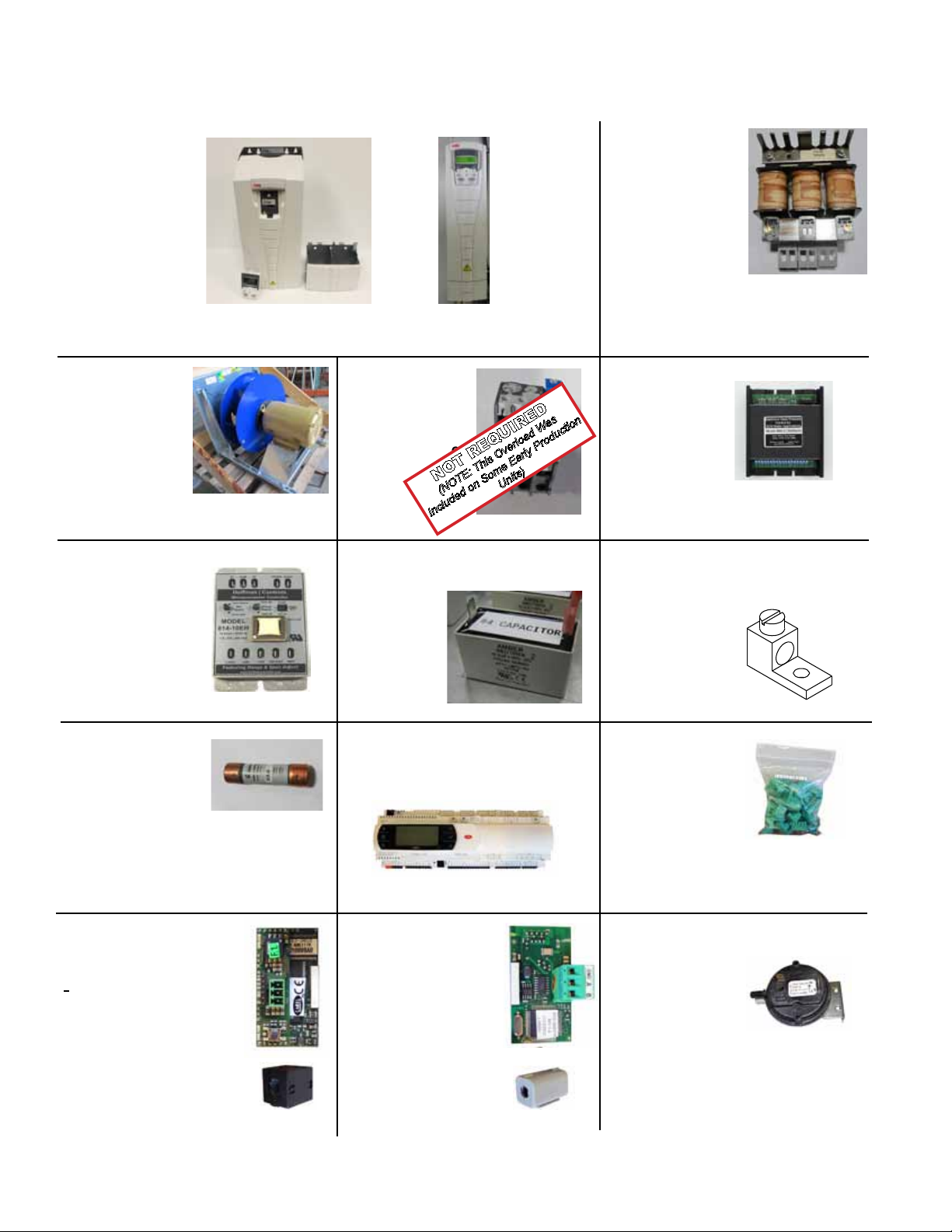
pages 8, 9 & 10. For an Illustration of most parts, see pages 12, 16 & 17.
Code 7 -
VFD
Part Number
Varies Reference
Tables on Pages
12 thru 15
Code 9 -
Supply Fan
(Part Number
Varies Refer to
tables shown on
pages 12 thru 15)
Code 12 Low
Ambient
Controller for
Std Condenser
Fan Sensor - P/N
261042
(Control P/N
261041 not shown)
Variable Frequency
Drive Model ACS550
Variable Frequency
Drive Model ACS355
Code 10 -
Overload Relay
(Part Number
Varies Refer to
table on shown on
page 13)
NOT REQUIRED
(NOTE: This Overload Was
Included on Some Early Production
Code 13 -
Capacitor P/N 207448
Units)
Code 8 -
Line Reactor
(Part Number
Varies Refer to
tables shown on
Pages 12 thru 15)
Code 11 Low
Ambient
Controller
for ECM
Condenser Fan
- P/N 272460 &
Sensor - P/N
272461 (not
shown)
Code 14 Grounding Lug
- P/N 179196
Codes 15, 28 &
190
Fuse- P/N’s:
207615 (30Amp),
207617 (60Amp),
207627 (45Amp)
Code 18 BacNet DDC
Communication Bus
“programmed”
(Opt BHB8):
P/N 272633 (for D19)
P/N 1006079 (for D21)
Includes shipped-loose
Ferrite Core for around
communication connection.
Ferrite Core
Form P-Y (6-16), PN 273651R23, Page 16
Code 16 - Carel Digital
Controller w/ Programmed
Software, Opt D19 or D21
Code 19 LON DDC
CommunicationBus,
“programmed”
(Opt BHB7):
P/N 284991N (for D19)
P/N 284992 (for D21)
Includes shipped-loose
Ferrite Core for around
communication connection.
Ferrite Core
Code 17
Carel Plugs
P/N 272630
Codes 20, 22 & 34
Pressure Switch,
P/N 234712
Page 17

Code 21 - Relay & Base,
P/N 211411 (2 pole)
(Use 211415 base)
P/N211799 (3 pole)
(Use 211800 base)
Codes 23, 24
& 47
Filter Pressure
Switch,
P/N 105507
Code 25
Terminal Strip,
P/N 164545
Codes 26, 45 & 46
Duct Static Pressure
Transducer,
(Part Number Varies Refer
to table shown on page 9)
Sensor Port,
P/N 234821
Code 31
Distribution
Block,
P/N 223495
& 188
Contactor,
(Part Number
Varies Refer to
tables shown on
pages 37 thru 39
& 45)
Code 32
High Venter
Combustion Air
Switch
(
Refer to tables shown
on pages 18 & 19)
Part Number Varies
Code 30Codes 4, 29, 172
SCR Controller
(Part Number
Varies Refer to
tables shown on
pages 37 thru 40)
Code 33
Low Venter
Combustion Air
Switch
(Part Number Varies
Refer to table shown on
page 18)
Form P-Y (6-16), PN 273651R23, Page 17
Page 18

Electrical Components - Replacement P/N’s (Cont’d)
For Component Location: Cabinet 1A & 1B, see pages 5, 6 & 10; Cabinet 2, see pages 7 & 10, Cabinet 3, see
pages 8, 9 & 10. For an Illustration of most parts, see pages 12, 16 & 17.
Code No’s 32 & 33 Combustion Air Switches for Sea Level to 6000 ft. (1830 m)
Code #32 High Pressure Switch Code #33 Low Pressure Switch (AG73 & AG74 Only)
P/N
230, 460,
575V
% Full
Speed of
Venter Mtr
Heat
Section
Option
Heat
Size(s)
(Btuh)
Startup
Cold
Equilibrium
Hot
Setpoint
Off
Label
Color
Switch
P/N
Startup
Cold
Equilibrium
Hot
Setpoint
Off
Label
Color
Switch
Negative Pressure (iwc) Negative Pressure (iwc)
H50 50,000 3.10 2.00 1.50 Yellow 273360 3.50 1.30 0.75 Yellow 205443 74 82
H75 75,000 3.30 1.60 1.40 Red 201159 3.30 1.30 1.00 Brown 201160 74 82
H100 100,000 3.40 1.70 1.40 Red 201159 3.40 1.20 1.00 Brown 201160 74 82
H102* 50,000 3.10 2.00 1.50 Yellow 273360 3.50 1.30 0.75 Yellow 205443 74 82
H125*
50,000 3.10 2.00 1.50 Yellow 273360 (No low pressure switch on this furnace)
75,000 3.30 1.60 1.40 Red 201159 3.30 1.30 1.00 Brown 201160 74 82
H150* 75,000 3.30 1.60 1.40 Red 201159 3.30 1.30 1.00 Brown 201160 74 82
H175*
75,000 3.30 1.60 1.40 Red 201159 (No low pressure switch on this furnace)
100,000 3.40 1.70 1.40 Red 201159 3.40 1.20 1.00 Brown 201160 74 82
H200 200,000 3.80 1.80 1.40 Red 201159 3.80 0.90 0.75 Yellow 205443 42 54
H202* 100,000 3.40 1.70 1.40 Red 201159 3.40 1.20 1.00 Brown 201160 74 82
H300 300,000 3.90 1.90 1.50 Yellow 273360 3.90 0.90 0.75 Yellow 205443 48 56
H400 400,000 3.80 1.80 1.50 Yellow 273360 3.80 1.00 0.80 Gray 197078 58 64
H402* 200,000 3.80 1.80 1.40 Red 201159 3.80 0.90 0.75 Yellow 205443 42 54
H502
200,000 3.80 1.80 1.40 Red 201159 (No low pressure switch on this furnace)
300,000 3.90 1.90 1.50 Yellow 273360 3.90 0.90 0.75 Yellow 205443 48 56
H602* 300,000 3.90 1.90 1.50 Yellow 273360 3.90 0.90 0.75 Yellow 205443 42 56
H702
300,000 3.90 1.90 1.50 Yellow 273360 (No low pressure switch on this furnace)
400,000 3.80 1.80 1.50 Yellow 273360 3.80 1.00 0.80 Gray 197078 58 64
H802* 400,000 3.80 1.80 1.50 Yellow 273360 3.80 1.00 0.80 Gray 197078 58 64
208V
% Full
Speed of
Venter Mtr
Code #32 High Pressure Switch Code #33 Low Pressure Switch (AG73 & AG74 Only)
Heat
Section
Option
Heat
Size(s)
(Btuh)
Startup
Cold
Equilibrium
Hot
Setpoint
Off
Label
Color
Switch
P/N
Startup
Cold
Equilibrium
Hot
Setpoint
Off
Label
Color
Switch
P/N
230, 460,
575V
% Full
Speed of
Venter Mtr
208V
% Full
Speed of
Venter Mtr
Negative Pressure (iwc) Negative Pressure (iwc)
G150 150,000 2.70 2.20 1.40 Red 201159 2.70 1.70 0.10 White 234712 61 74
G225 225,000 2.90 2.50 1.40 Red 201159 2.90 1.30 0.10 White 234712 61 74
G300 300,000 2.70 2.50 1.30 White 201161 2.70 0.90 0.10 White 234712 61 74
G302* 150,000 2.70 2.20 1.40 Red 201159 2.70 1.70 0.10 White 234712 61 74
G372
150,000 2.70 2.20 1.40 Red 201159 (No low pressure switch on this furnace)
225,000 2.90 2.50 1.40 Red 201159 2.90 1.30 0.10 White 234712 61 74
G452* 225,000 2.90 2.50 1.40 Red 201159 2.90 1.30 0.10 White 234712 61 74
G525
225,000 2.90 2.20 1.40 Red 201159 (No low pressure switch on this furnace)
300,000 2.70 2.50 1.30 White 201161 2.70 0.90 0.10 White 234712 61 74
G602* 300,000 2.70 2.50 1.30 White 201161 2.70 0.90 0.10 White 234712 61 74
* Heat sections with dual furnaces. When only one size is listed, both furnaces are the same size and two identical high pres-
sure switches are used. Dual furnace heat sections with electronic modulation Option AG74 have one low pressure switch.
Form P-Y (6-16), PN 273651R23, Page 18
Page 19

Code No 32 Combustion Air Switches for Above 6000 ft. (1830 m)
Heat
Section
Option
Heat
Size(s)
(Btuh)
Code #32 High Pressure Switch
Setpoint
Off
Label
Color
Switch
P/N
Negative Pressure (iwc) Negative Pressure (iwc)
Heat
Section
Option
Heat
Size(s)
(Btuh)
Code #32 High Pressure Switch
Setpoint
Off
Label
Color
Switch P/N
H50 50,000 1.45 Orange 273555 H300 300,000 1.45 Orange 273555
H75 75,000 1.35 Green 273554 H400 400,000 1.45 Green 273555
H100 100,000 1.35 Green 273554 H402* 200,000 1.35 Green 273554
H102* 50,000 1.45 Orange 273555
H150* 75,000 1.35 Green 273554 300,000 1.45 Orange 273555
H175*
75,000 1.35 Green 273554 H602* 300,000 1.45 Orange 273555
100,000 1.35 Green 273554
H200 200,000 1.35 Green 273554 400,000 1.45 Orange 273555
H502*
H702*
200,000 1.35 Green 273554
300,000 1.45 Orange 273555
H202* 100,000 1.35 Green 273554 H802 400,000 1.45 Orange 273555
Heat
Section
Option
Heat
Size(s)
(Btuh)
Code #32 High Pressure Switch
Setpoint
Off
Label
Color
Switch
P/N
Negative Pressure (iwc) Negative Pressure (iwc)
Heat
Section
Option
Heat
Size(s)
(Btuh)
Code #32 High Pressure Switch
Setpoint
Off
Label
Color
Switch P/N
G150 150,000 1.35 Green 273554 G452* 225,000 1.35 Green 273554
G225 225,000 1.35 Green 273554
G300 300000 1.25 Blue 273553 300,000 1.25 Blue 273553
G525
225,000 1.35 Green 273554
G302* 150000 1.35 Green 273554 G602 300,000 1.25 Blue 273553
G372*
150,000 1.35 Green 273554
225,000 1.35 Green 273554
* Heat sections with dual furnaces. When only one size is listed, both furnaces are the same size and two identical high pres-
sure switches are used. Dual furnace heat sections with electronic modulation Option AG74 have one low pressure switch.
Form P-Y (6-16), PN 273651R23, Page 19
Page 20

Electric Components - Gas Heat Section
For Component Location see Gas Heat Section Control Panel on page 8.
Code 35 - Venter Speed Controller- for P/N’s Reference “Voltage Options” Table Shown Below
Voltage Options
Model
H50, H75, H100,
H102, H125, H150,
H175, H202
H200, H402 235286 235638
H300, H502, H602 235287 213576
G150, G225, G300,
G302, G372, G452,
G525, G602
H400, H702, H802 235288 213580
AK3 (230/1/60),
AK6 (230/3/60),
AK7 (460/3/60),
AK8 (575/3/60)
235290 235639
235289 235290
AK5 (208/3/60)
P/N of
Control
213576 56 ON ON ON OFF ON OFF ON ON
213580 64 OFF ON ON ON ON OFF ON ON
235286 42 ON ON OFF ON OFF OFF ON ON
235287 48 OFF OFF OFF OFF ON OFF ON ON
235288 58 ON OFF OFF ON ON OFF ON ON
235289 61 ON ON OFF ON ON OFF ON ON
235290 74 OFF ON ON OFF OFF ON ON ON
235638 54 ON OFF ON OFF ON OFF ON ON
235639 82 OFF ON ON ON OFF ON ON ON
% of
Full
Speed
Venter Speed Controller DIP Switch Settings
1 2 3 4 5 6 7 8
Code 36
Relay Rib
Board,
P/N 234656
Code 41
Space Temp
Sensor
P/N 272631
Codes 48 & 49
Averaging
Temp Sensor
P/N 271993 &
271994
Code 37
DSI Control
Module,
P/N 272626
Code 44
Photoelectric
Smoke
Detector (in
ductwork),
P/N 159553
Code 50
Convenience
Outlet 125v,
P/N 272900
Code 39 -
Outside Air
Humidity
Sensor,
P/N 222754
Codes 40, 42
Air Temp Sensor
w/ 8”Probe
P/N 222753
Code 46
CO2 Sensor
P/N 234820
Code 51
Firestat
(200°F),
P/N 42782
Code 53 - Disconnect Switch Unit-Mounted
(Option BA6_) - for P/N’s Refer to Table
Shown Below
Cabinet
1, 2 or 3
Form P-Y (6-16), PN 273651R23, Page 20
Models Size Voltage
Size
60, 90, 120, 150,
YDHA
YDMA
YDSA
180, 210, 240,
300, 360
120, 150, 180,
210
208, 230,
460, 575
Option
No
BA6A 60 205906
BA6B 80 205907
BA6C 100 205908
BA6D 125 207678
BA6E 200 207679
BA6F 250 222422
Amp
Disconnect
Switch P/N
Code 54 - Raintight
Disconnect Switch
(Option CP_) - for
P/N’s Refer to Table
Shown Below
Where Voltage Description P/N Same as
Installed
in USA
Installed
in
Canada
60 amp, 240 volt, fusible 89932 CP 17
100 amp, 240 volt, fusible 90973 CP 18
240
Max
200 amp, 240 volt, fusible 91076 CP 19
400 amp, 240 volt, fusible 223658 CP 72
60 amp, 600 volt, fusible 90974 CP 20
100 amp, 600 volt, fusible 155010 CP 36
600
Max
200 amp, 600 volt, fusible 155011 CP 37
400 amp, 600 volt, fusible 223659 CP 76
60 amp, 600 volt, fusible 208048 CP 44
100 amp, 600 volt, fusible 208174 CP 46
600
Max
200 amp, 600 volt, fusible 208176 CP 48
400 amp, 600 volt, fusible 223661 CP 80
Page 21

Electric Components (Cont’d)
Single Heat Section Module Assemblies
Cabinet
Size
1
2
3
Type of Efciency Heat Size
Standard H50 272355
H75 272356
H100 272357
H200 272358
H300 272359
H400 272360
High Efciency G150 273379
G225 273380
G300 273381
Standard H75 272356
H100 272357
H200 272358
H300 272359
H400 272360
High Efciency G150 273379
G225 273380
G300 273381
Standard H200 272358
H300 272359
H400 272360
High Efciency G150 273379
G225 273380
G300 273381
Heat Section
Module
Dual Heat Section Module Assemblies
Heat Section Module
LEFT SIDE
Cabinet
Size
1
2
3
Type of Efciency Heat Size
Standard H102 272355 272355
H125 272355 272356
H150 272356 272356
H175 272356 272357
H202 272357 272357
H402 272358 272358
High
Efciency
Standard
High
Efciency
Standard
High
Efciency
G302 273379 273379
G372 273379 273380
H102 272355 272355
H125 272355 272356
H150 272356 272356
H175 272356 272357
H202 272357 272357
H402
H502 272358 272359
H602 272359 272359
G302 273379 273379
G372 273379 273380
G452 273380 273380
H150
H175
H202
H402
H502 272358 272359
H602 272359 272359
H702 272359 272360
H802 272360 272360
G302 273379 273379
G372 273379 237780
G452 273380 273380
G525 273380 273381
G602 273381 273381
Heat Section Module
Left Side Right Side
272358 272358
272356 272356
272356 272357
272357 272357
272358 272358
Heat Section Module
RIGHT SIDE
Form P-Y (6-16), PN 273651R23, Page 21
Page 22

Gas Heat Components (Cont’d)
NOTE: Heat sections illustrated are standard efciency, non-condensing furnaces. Controls for condensing furnaces are the same
except for venter assemblies.
Single Heat Section
Manifold Assembly with
2-Stage Option AG71
Flue
Collection
Box
Manifold Pressure Tap
Limit
Ignitor
Venter
Assembly
Optional
High Gas
Pressure
Switch
2-Stg
Gas
Valve
Optional
Low Gas
Pressure
Switch
Option AG 71 - Single Heat Section Manifold Code Number Details:
WITH: AA1 - Natural Gas Option with BP1 Standard Manifold.
AA1 - Natural Gas Option with BP4 Manifold with High & Low Pressure Switches.
AA2 - Propane Option with BP1 Standard Manifold.
AA2 - Propane Option with BP4 Manifold and High & Low Gas Pressure Switches.
Code Description
H50 H75 H100 H200 H300 H400 G150 G225 G300
56 Heat Exchanger Assy See Single & Dual Heat Section Mod Ass’y Tables on Page 21
57 Spark Ignitor 272742
58 Limit Control 272740 272741 272740 272741 272740
59 Flame Sensor 272743
60 Gas Valve:
AA1 - Natural Gas Option 177396 177397 177396 177397
AA2 - Propane Option --- 177395 177398 ---
61 BP4 Optional Low Gas Pressure Switch 204375
62 BP4 Optional High Gas Pressure Switch 204297
63 Venter Assembly See Standard Efciency Gas Venter Assembly Usage Table on Page 45
H50 H75 H100 H200 H300 H400 G150 G225 G300
Standard Efciency High Efciency
Form P-Y (6-16), PN 273651R23, Page 22
Page 23

NOTE: Heat sections illustrated are standard efciency, non-condensing furnaces. Controls for condensing furnaces are the same
except for venter assemblies.
Dual Heat Section
Manifold Assembly
with 4-Stage
Option AG72
Optional High Gas
Manifold Pressure Tap
Venter
Assembly
Pressure Switch
Limit
Ignitor
Heat Section 2
2-Stg
Valve
Venter
Assembly
Optional
High Gas
Pressure
Switch
Ignitor
Limit
Manifold Pressure Tap
Heat Section 1
2-Stg
Valve
Optional Low
Gas Pressure
Switch
Option AG72 - Dual Heat Section Manifold Code Number Details:
WITH: AA1 - Natural Gas Option with BP1 Standard Manifold.
AA1 - Natural Gas Option with BP4 Manifold with High & Low Pressure Switches.
AA2 - Propane Option with BP1 Standard Manifold.
AA2 - Propane Option with BP4 Manifold with High & Low Pressure Switches.
Code Description
H102 H125 H150 H175 H202 H402 H502 H602 H702 H802 G302 G372 G452 G525 G602
65 & 72 Heat Exchanger Assy See Single & Dual Heat Section Mod Ass’y Tables on Page 21
66 & 73 Spark Ignitor 272742
67 Limit Control 272740 272741 272740 272741 272740
74 Limit Control 272740 272741 272740 272741 272740 272741 272740
68 Gas Valve:
AA1 - Natural Gas Option
69 & 76
AA2 - Propane Option
Flame Sensor
(typical all AA_ options)
--- 177395 177398 ---
70 & 78 BP4 Optional High Gas
Pressure Switch
71 & 79 Venter Assembly See Standard Efciency Gas Venter Assembly Usage Table on Page 45
75
Gas Valve:
AA1 - Natural Gas Option
AA2 - Propane Option
177396 177397 177396 177397
--- 177395 177398 ---
77 BP4 Optional Low Gas
Pressure Switch
80 Flexible Gas Connection 273794 120875 273794 120875
H102 H125 H150 H175 H202 H402 H502 H602 H702 H802 G302 G372 G452 G525 G602
Standard Efciency High Efciency
177396 177397 177396 177397
272743
204297
204375
Form P-Y (6-16), PN 273651R23, Page 23
Page 24

Optional High Gas
Pressure Switch
Ignitor
Venter
Assembly
Manifold Pressure Tap
Optional
Low Gas
Pressure
Switch
1-Stg
Valve
Modulating Valve
Venter
Control
Pressure
Switch
Single Heat
Section Manifold
Assembly with
Electronic
Modulation
Option AG73
Gas Heat Components (Cont’d)
NOTE: Heat sections illustrated are standard efciency, non-condensing furnaces. Controls for condensing furnaces are the same
except for venter assemblies.
Option AG 73 - Single Heat Section Manifold Code Number Details:
WITH: AA1 - Natural Gas Option with BP1 Standard Manifold.
AA1 - Natural Gas Option with BP4 Manifold with High & Low Pressure Switches.
AA2 - Propane Option with BP1 Standard Manifold.
AA2 - Propane Option with BP4 Manifold and High & Low Gas Pressure Switches.
Code Description
H50 H75 H100 H200 H300 H400 G150 G225 G300
85 Heat Exchanger Assy See Single & Dual Heat Section Mod Ass’y Tables on Page 21
Spark Ignitor
86
(typical all AA_ options)
87
Limit Control: 272740 272741 272740 272741 272740
Flame Sensor
88
(typical all AA_ options)
89 Gas Valve:
AA1 - Natural Gas Option 260604 150839 260604 150539
AA2 - Propane Option --- 260606 150840 ---
90 BP4 Optional Low Gas
Pressure Switch:
91 BP4 Optional High Gas
Pressure Switch:
92 Venter Assembly See Standard Efciency Gas Venter Assembly Usage Table on Page 45
93 Modulating Valve:
AA1 - Natural Gas Option 273587 271840 273588 271840 273588
AA2 - Propane Option --- 271840 273588 ---
94 Gas Pressure Switch:
AA1 - Natural Gas Option 211130
AA2 - Propane Option 211710
H50 H75 H100 H200 H300 H400 G150 G225 G300
Standard Efciency High Efciency
272742
272743
204375
204297
Form P-Y (6-16), PN 273651R23, Page 24
Page 25

NOTE: Heat sections illustrated are standard efciency, non-condensing furnaces. Controls for condensing furnaces are the same
except for venter assemblies.
Dual Heat Section
Manifold Assembly
with Electronic
Modulation
Option AG74
Venter
Assembly
Venter
Assembly
Optional High Gas
Pressure Switch
Limit
Ignitor
Manifold Pressure Tap
Heat Section 2
2-Stg
Valve
Optional
High Gas
Pressure
Switch
Venter Control
Pressure Switch
Modulating
Valve
1-
Stg
Valve
Manifold Pressure Tap
Heat Section 1
Option AG74 - Dual Heat Section Manifold Code Number Details:
WITH: AA1 - Natural Gas Option with BP1 Standard Manifold.
AA1 - Natural Gas Option with BP4 Manifold with High & Low Pressure Switches.
AA2 - Propane Option with BP1 Standard Manifold.
AA2 - Propane Option with BP4 Manifold with High & Low Pressure Switches.
Code Description
H102 H125 H150 H175 H202 H402 H502 H602 H702 H802
96 & 103 Heat Exchanger Assy See Single & Dual Heat Section Mod Ass’y Tables on Page 21
97 & 104
Spark Ignitor
(typical all AA_ options)
Limit Control
98
(typical all AA_ options)
Limit Control
105
(typical all AA_options)
272740 272741 272740 272741
272740 272741 272740 272741 272740 272741
99 Gas Valve:
100 & 107
AA1 - Natural Gas Option
AA2 - Propane Option
Flame Sensor
(typical all AA_ options)
177396 177397
--- 177395 177398
101 & 109 Optional High Gas
Pressure Switch:
102 & 110 Venter Assembly See Standard Efciency Gas Venter Assembly Usage Table on Page 45
106 Gas Valve:
AA1 - Natural Gas Option
AA2 - Propane Option
--- 260604 150839
--- 260606 150840
108 Optional Low Gas
Pressure Switch
111 Modulating Valve:
AA1 - Natural Gas Option
AA2 - Propane Option
273587 271840 273588
--- 271840 273588
112 Gas Pressure Switch:
AA1 - Natural Gas
AA2 - Propane Option
113 Flexible Gas Connection 273794 120875
H102 H125 H150 H175 H202 H402 H502 H602 H702 H802
Standard Efciency
272742
272743
204297
204375
211130
211710
Optional
Optional
Low Gas
Low Gas
Pressure
Pressure
Switch
Switch
(See Next Page)
High Efciency Data
Form P-Y (6-16), PN 273651R23, Page 25
Page 26

Gas Heat Components (Cont’d)
NOTE: Heat sections illustrated are standard efciency, non-condensing furnaces. Controls for condensing furnaces are the same
except for venter assemblies.
Option AG74 - Dual Heat Section Manifold Code Number Details:
WITH: AA1 - Natural Gas Option with BP1 Standard Manifold.
AA1 - Natural Gas Option with BP4 Manifold with High & Low Pressure Switches.
AA2 - Propane Option with BP1 Standard Manifold.
AA2 - Propane Option with BP4 Manifold with High & Low Pressure Switches.
Code Description
96 & 103 Heat Exchanger Assy See Single & Dual Heat Section Mod Ass’y Tables on Page 21
97 & 104
100 & 107
101 & 109 Optional High Gas
102 & 110 Venter Assembly See Standard Efciency Gas Venter Ass’y Usage Table on Page 45
Spark Ignitor
(typical all AA_ options)
Limit Control
98
(typical all AA_ options)
Limit Control
105
(typical all AA_options)
99 Gas Valve:
AA1 - Natural Gas Option
AA2 - Propane Option
Flame Sensor
(typical all AA_ options)
Pressure Switch:
106 Gas Valve:
AA1 - Natural Gas Option 150839 260604
AA2 - Propane Option 150840
108 Optional Low Gas
Pressure Switch
111 Modulating Valve:
AA1 - Natural Gas Option
AA2 - Propane Option
112 Gas Pressure Switch:
AA1 - Natural Gas
AA2 - Propane Option
113 Flexible Gas Connection --- 273794 120875
Standard Efciency Data
G150 G302 G372 G452 G525 G602
--- 272740
--- 272740
--- 177396 177397
(See Previous Page)
--- 271840 273588
G150 G302 G372 G452 G525 G602
High Efciency
272742
---
272743
204297
150839
---
204375
---
211130
211710
Form P-Y (6-16), PN 273651R23, Page 26
Page 27

For Component Locations - See illustrations shown on pages 22 thru 26
Codes 57, 66, 73,
86, 97 & 104
Spark Ignitor
P/N 272742.
Codes 60, 68, 75,
89, 99 & 106
Gas Valve
P/N’s Vary - Ref
Option AG71, 72,
73&74 Tables on
Pages 22 thru 25.
Codes 62, 70, 78,
91, 101 & 109
High Gas
Pressure Switch
P/N 204297.
(Option BP4)
Codes 58, 67, 74,
87, 98 & 105
Limit Control
P/N’s Vary - Ref
Option AG71, 72,
73&74 Tables on
Pages 22 thru 25.
Codes 59, 69, 76,
88, 100 & 107
Flame Sensor
P/N 272743.
Codes 61, 77,
90 and 108
Low Gas
Pressure
Switch
P/N 204375.
(Option BP4)
Codes 93 & 111
Modulating Valve
P/N’s Vary - Ref
Options AG73
& 74 Tables on
Pages 24, 25 & 26.
Codes 94 & 112
Gas Press Switch
P/N’s Vary - Ref
Options AG73 & 74
Tables on Pages
24, 25 & 26.
Codes 80 &113
Flexible Gas
Connection
P/N’s Vary - Ref
Options AG72 & 74
Tables on Pages
23, 25 & 26.
Form P-Y (6-16), PN 273651R23, Page 27
Page 28

GAS ORIFICE
MANIFOLD
Elevation Adjustment (U.S.) Options for Gas Orice Replacement Table
(Note: For Canadian elevations below 2,000 ft / 600 M select Option AB1 & for elevations above 2,000 ft select Option AB4)
AB1 (0 - 2,000 ft) AB2 (2,001 - 3,000 ft)
Heat Option
H50
H75
H100
H102 (Left Unit)
H102 (Right Unit)
H125 (Left Unit)
H125 (Right Unit)
H150 (Left Unit)
H150 (Right Unit)
H175 (Left Unit)
H175 (Right Unit)
H200
H202 (Left Unit)
H202 (Right Unit)
H300
H400
H402 (Left Unit)
H402 (Right Unit)
H502 (Left Unit)
H502 (Right Unit)
H602 (Left Unit)
H602 (Right Unit)
H702 (Left Unit)
H702 (Right Unit)
H802 (Right Unit)
H802 (Right Unit)
AA1 (Nat Gas) AA2 (Propane) AA1 (Nat Gas) AA2 (Propane)
P/N Marking P/N Marking P/N Marking P/N Marking
273355 48
273356 49
273355 48
273355 48
273355 48
273355 48
273356 49
273356 49
273356 49
273356 49
273355 48
273344 30
273355 48
273355 48
273344 30
273344 30
273344 30
273344 30
273344 30
273344 30
273344 30
273344 30
273344 30
273344 30
273344 30
273344 30
--- --
--- --
--- --
--- --
--- --
--- --
--- --
--- --
--- --
--- --
--- --
273352 46
--- --
--- -273352 46
273352 46
273352 46
273352 46
273352 46
273352 46
273352 46
273352 46
273352 46
273352 46
273352 46
273352 46
273356 49
273357 50
273356 49
273356 49
273356 49
273356 49
273357 50
273357 50
273357 50
273356 49
273357 50
273353 46
273356 49
273356 49
273344 30
273344 30
273344 30
273344 30
273344 30
273344 30
273344 30
273344 30
273344 30
273344 30
273344 30
273344 30
--- -- 3
--- -- 5
--- -- 6
--- -- 3
--- -- 3
--- -- 3
--- -- 5
--- -- 5
--- -- 5
--- -- 5
--- -- 6
273353 47 4
--- -- 6
--- -- 6
273353 47 6
273353 47 8
273353 47 4
273353 47 4
273353 47 4
273353 47 6
273353 47 6
273353 47 6
273353 47 6
273353 47 8
273353 47 8
273353 47 8
QTY
Form P-Y (6-16), PN 273651R23, Page 28
Page 29

Heat Option
G150
G225
G300
G302 (Left Hand)
G302 (Right Hand)
G372 (Left Hand)
G372 (Right Hand)
G452 (Left Hand)
G452 (Right Hand)
G525 (Left Hand)
G525 (Right Hand)
G602 (Left Hand)
G602 (Right Hand)
Heat Option
H50
H75
H100
H102 (Left Unit)
H102 (Right Unit)
H125 (Left Unit)
H125 (Right Unit)
H150 (Left Unit)
H150 (Right Unit)
H175 (Left Unit)
H175 (Right Unit)
H200
H202 (Left Unit)
H202 (Right Unit)
H300
H400
H402 (Left Unit)
H402 (Right Unit)
H502 (Left Unit)
H502 (Right Unit)
H602 (Left Unit)
H602 (Right Unit)
H702 (Left Unit)
H702 (Right Unit)
H802 (Right Unit)
H802 (Right Unit)
AB1 (0 - 2,000 ft) AB2 (2,001 - 3,000 ft)
AA1 (Nat Gas) AA2 (Propane) AA1 (Nat Gas) AA2 (Propane)
P/N Marking P/N Marking P/N Marking P/N Marking
273346 32
273346 32
273346 32
273346 32
273346 32
273346 32
273346 32
273346 32
273346 32
273346 32
273346 32
273346 32
273346 32
--- --
--- --
--- --
--- --
--- --
--- --
--- --
--- --
--- --
--- --
--- --
--- --
--- --
273347 33
273347 33
273347 33
273347 33
273347 33
273347 33
273347 33
273347 33
273347 33
273347 33
273347 33
273347 33
273347 33
--- -- 4
--- -- 6
--- -- 8
--- -- 4
--- -- 4
--- -- 4
--- -- 6
--- -- 6
--- -- 6
--- -- 6
--- -- 8
--- -- 8
--- -- 8
AB3 (3,001 - 4,000 ft) AB4 (4,001 - 5,000 ft)
AA1 (Nat Gas) AA2 (Propane) AA1 (Nat Gas) AA2 (Propane)
P/N Marking P/N Marking P/N Marking P/N Marking
273356 49
273357 50
273356 49
273356 49
273356 49
273356 49
273357 50
273357 50
273357 50
273356 49
273357 50
273345 31
273356 49
273356 49
273345 31
273345 31
273345 31
273345 31
273345 31
273345 31
273345 31
273345 31
273345 31
273345 31
273345 31
273345 31
--- --
--- --
--- --
--- --
--- --
--- --
--- --
--- --
--- --
--- --
--- --
273354 47
--- --
--- -273354 47
273354 47
273354 47
273354 47
273354 47
273354 47
273354 47
273354 47
273354 47
273354 47
273354 47
273354 47
273356 49
273357 50
273356 49
273356 49
273356 49
273356 49
273357 50
273357 50
273357 50
273356 49
273357 50
273345 31
273356 49
273356 49
273345 31
273345 31
273345 31
273345 31
273345 31
273345 31
273345 31
273345 31
273345 31
273345 31
273345 31
273345 31
--- -- 3
--- -- 5
--- -- 6
--- -- 3
--- -- 3
--- -- 3
--- -- 5
--- -- 5
--- -- 5
--- -- 5
--- -- 6
273354 47 4
--- -- 6
--- -- 6
273354 47 6
273354 47 8
273354 47 4
273354 47 4
273354 47 4
273354 47 6
273354 47 6
273354 47 6
273354 47 6
273354 47 8
273354 47 8
273354 47 8
QTY
QTY
Form P-Y (6-16), PN 273651R23, Page 29
Page 30

Elevation Adjustment (U.S.) Options for Gas Orice Replacement Table (Cont’d)
(Note: For Canadian elevations below 2,000 ft / 600 M select Option AB1 & for elevations above 2,000 ft select Option AB4)
AB3 (3,001 - 4,000 ft) AB4 (4,001 - 5,000 ft)
Heat Option
G150
G225
G300
G302 (Left Hand)
G302 (Right Hand)
G372 (Left Hand)
G372 (Right Hand)
G452 (Left Hand)
G452 (Right Hand)
G525 (Left Hand)
G525 (Right Hand)
G602 (Left Hand)
G602 (Right Hand)
Heat Option
H50
H75
H100
H102 (Left Unit)
H102 (Right Unit)
H125 (Left Unit)
H125 (Right Unit)
H150 (Left Unit)
H150 (Right Unit)
H175 (Left Unit)
H175 (Right Unit)
H200
H202 (Left Unit)
H202 (Right Unit)
H300
H400
H402 (Left Unit)
H402 (Right Unit)
H502 (Left Unit)
H502 (Right Unit)
H602 (Left Unit)
H602 (Right Unit)
H702 (Left Unit)
H702 (Right Unit)
H802 (Right Unit)
H802 (Right Unit)
AA1 (Nat Gas) AA2 (Propane) AA1 (Nat Gas) AA2 (Propane)
P/N Marking P/N Marking P/N Marking P/N Marking
273348 34
273348 34
273348 34
273348 34
273348 34
273348 34
273348 34
273348 34
273348 34
273348 34
273348 34
273348 34
273348 34
--- --
--- --
--- --
--- --
--- --
--- --
--- --
--- --
--- --
--- --
--- --
--- --
--- --
273349 35
273349 35
273349 35
273349 35
273349 35
273349 35
273349 35
273349 35
273349 35
273349 35
273349 35
273349 35
273349 35
--- -- 4
--- -- 6
--- -- 8
--- -- 4
--- -- 4
--- -- 4
--- -- 6
--- -- 6
--- -- 6
--- -- 6
--- -- 8
--- -- 8
--- -- 8
AB5 (5,001 - 6,000 ft) AB6 (6,001 - 7,000 ft)
AA1 (Nat Gas) AA2 (Propane) AA1 (Nat Gas) AA2 (Propane)
P/N Marking P/N Marking P/N Marking P/N Marking
273357 50
273358 51
273357 50
273357 50
273357 50
273357 50
273358 51
273358 51
273358 51
273357 50
273358 51
273345 31
273357 50
273357 50
273345 31
273345 31
273345 31
273345 31
273345 31
273345 31
273345 31
273345 31
273345 31
273345 31
273345 31
273345 31
--- --
--- --
--- --
--- --
--- --
--- --
--- --
--- --
--- --
--- --
--- --
273354 47
--- --
--- -273354 47
273354 47
273354 47
273354 47
273354 47
273354 47
273354 47
273354 47
273354 47
273354 47
273354 47
273354 47
273357 50
273358 51
273357 50
273357 50
273357 50
273357 50
273358 51
273358 51
273358 51
273357 50
273358 51
273345 31
273357 50
273357 50
273345 31
273345 31
273345 31
273345 31
273345 31
273345 31
273345 31
273345 31
273345 31
273345 31
273345 31
273345 31
--- -- 3
--- -- 5
--- -- 6
--- -- 3
--- -- 3
--- -- 3
--- -- 5
--- -- 5
--- -- 5
--- -- 5
--- -- 6
273355 48 4
--- -- 6
--- -- 6
273355 48 6
273355 48 8
273355 48 4
273355 48 4
273355 48 4
273355 48 6
273355 48 6
273355 48 6
273355 48 6
273355 48 8
273355 48 8
273355 48 8
QTY
QTY
Form P-Y (6-16), PN 273651R23, Page 30
Page 31

Heat Option
G150
G225
G300
G302 (Left Hand)
G302 (Right Hand)
G372 (Left Hand)
G372 (Right Hand)
G452 (Left Hand)
G452 (Right Hand)
G525 (Left Hand)
G525 (Right Hand)
G602 (Left Hand)
G602 (Right Hand)
Heat Option
H50
H75
H100
H102 (Left Unit)
H102 (Right Unit)
H125 (Left Unit)
H125 (Right Unit)
H150 (Left Unit)
H150 (Right Unit)
H175 (Left Unit)
H175 (Right Unit)
H200
H202 (Left Unit)
H202 (Right Unit)
H300
H400
H402 (Left Unit)
H402 (Right Unit)
H502 (Left Unit)
H502 (Right Unit)
H602 (Left Unit)
H602 (Right Unit)
H702 (Left Unit)
H702 (Right Unit)
H802 (Right Unit)
H802 (Right Unit)
AB5 (5,001 - 6,000 ft) AB6 (6,001 - 7,000 ft)
AA1 (Nat Gas) AA2 (Propane) AA1 (Nat Gas) AA2 (Propane)
P/N Marking P/N Marking P/N Marking P/N Marking
273349 35
273349 35
273349 35
273349 35
273349 35
273349 35
273349 35
273349 35
273349 35
273349 35
273349 35
273349 35
273349 35
--- --
--- --
--- --
--- --
--- --
--- --
--- --
--- --
--- --
--- --
--- --
--- --
--- --
273350 36
273350 36
273350 36
273350 36
273350 36
273350 36
273350 36
273350 36
273350 36
273350 36
273350 36
273350 36
273350 36
--- -- 4
--- -- 6
--- -- 8
--- -- 4
--- -- 4
--- -- 4
--- -- 6
--- -- 6
--- -- 6
--- -- 6
--- -- 8
--- -- 8
--- -- 8
AB7 (7,001 - 8,000 ft) AB8 (8,001 - 9,000 ft)
AA1 (Nat Gas) AA2 (Propane) AA1 (Nat Gas) AA2 (Propane)
P/N Marking P/N Marking P/N Marking P/N Marking
273357 50
273358 51
273357 50
273357 50
273357 50
273357 50
273358 51
273358 51
273358 51
273357 50
273358 51
273346 32
273357 50
273357 50
273346 32
273346 32
273346 32
273346 32
273346 32
273346 32
273346 32
273346 32
273346 32
273346 32
273346 32
273346 32
--- --
--- --
--- --
--- --
--- --
--- --
--- --
--- --
--- --
--- --
--- --
273355 48
--- --
--- -273355 48
273355 48
273355 48
273355 48
273355 48
273355 48
273355 48
273355 48
273355 48
273355 48
273355 48
273355 48
273358 51
273359 52
273358 51
273358 51
273358 51
273358 51
273359 52
273359 52
273359 52
273358 51
273359 52
273346 32
273358 51
273358 51
273346 32
273346 32
273346 32
273346 32
273346 32
273346 32
273346 32
273346 32
273346 32
273346 32
273346 32
273346 32
--- -- 3
--- -- 5
--- -- 6
--- -- 3
--- -- 3
--- -- 3
--- -- 5
--- -- 5
--- -- 5
--- -- 5
--- -- 6
273356 49 4
--- -- 6
--- -- 6
273356 49 6
273356 49 8
273356 49 4
273356 49 4
273356 49 4
273356 49 6
273356 49 6
273356 49 6
273356 49 6
273356 49 8
273356 49 8
273356 49 8
QTY
QTY
Form P-Y (6-16), PN 273651R23, Page 31
Page 32

Elevation Adjustment (U.S.) Options for Gas Orice Replacement Table (Cont’d)
(Note: For Canadian elevations below 2,000 ft / 600 M select Option AB1 & for elevations above 2,000 ft select Option AB4)
AB7 (7,001 - 8,000 ft) AB8 (8,001 - 9,000 ft)
Heat Option
G150
G225
G300
G302 (Left Hand)
G302 (Right Hand)
G372 (Left Hand)
G372 (Right Hand)
G452 (Left Hand)
G452 (Right Hand)
G525 (Left Hand)
G525 (Right Hand)
G602 (Left Hand)
G602 (Right Hand)
AA1 (Nat Gas) AA2 (Propane) AA1 (Nat Gas) AA2 (Propane)
P/N Marking P/N Marking P/N Marking P/N Marking
273350 36
273350 36
273350 36
273350 36
273350 36
273350 36
273350 36
273350 36
273350 36
273350 36
273350 36
273350 36
273350 36
--- --
--- --
--- --
--- --
--- --
--- --
--- --
--- --
--- --
--- --
--- --
--- --
--- --
273351 37
273351 37
273351 37
273351 37
273351 37
273351 37
273351 37
273351 37
273351 37
273351 37
273351 37
273351 37
273351 37
--- -- 4
--- -- 6
--- -- 8
--- -- 4
--- -- 4
--- -- 4
--- -- 6
--- -- 6
--- -- 6
--- -- 6
--- -- 8
--- -- 8
--- -- 8
QTY
Form P-Y (6-16), PN 273651R23, Page 32
Page 33

Cooling and Dehumidifying Components - Refrigerant is R-410A.
Code 150
Compressor
P/N’s Vary - Ref
Tables on page
34, 40 & 41.
Code 153
Solenoid Kit
P/N 266071.
Code 156
High Pressure
Switch
P/N 216379.
Codes 5 &151
Digital Controller
P/N 266067.
Code 154
Coil Kit
P/N 266070.
Code 157
Low Pressure
Switch
P/N 216380.
Code 152
Thermister
P/N’s Vary - Refer
to Tables on
Pages 34, 40 &
41.
Code 155
Mounting Kit
P/N 205825.
Code 158
Molded Plugs
P/N’s Vary
Refer to
Tables on
pages 35 &
41.
Code 159
Expansion Valves
P/N’s Vary Refer to
Charts on pages
35 & 41.
Code 164
Fan Motor
P/N’s Vary
Refer to
Table on
page 36.
Code 167
Condenser Top
P/N 271817.
CUF3
CUF4
Code 160
Filter Driers
P/N’s Vary Refer
to Tables on
pages 35 & 41.
Code 165
Fan Blade
P/N’s Vary
Refer to
Table on
page 36.
Code 168 Fan
Guard
P/N 255436.
Code 161
Crankcase
Heaters
P/N’s Vary
Refer to Tables
on pages 35
& 41.
Code 166
Fan/Motor
Support
P/N 157107.
Form P-Y (6-16), PN 273651R23, Page 33
Page 34

Cooling and Dehumidifying Components (Cont’d)
See component illustrations page 33
Condenser Fan
Installation & Fan
Support
Condenser Fan Assembly Notes:
1) Locate the fan 1.00”down from the end of the motor shaft.
Compressor A
Compressor DH
Compressor B
2) Torque blade set screw to 120 in/lbs ±2 in/lbs.
3) Torque fan support motor retention bolt (located on fan hub)
to 95 in/lbs ±6 in/lbs.
End of Motor Shaft
1.00
(Isolator), P/N 268291
Isolation Hardware on
Condenser
Rubber Washer
Fender Washer,
P/N 194156
Flat Washer,
P/N 1087
P/N 217226
Fan Support
Top
Nut,
Screw, P/N 102033
Fender Washer,
P/N 194156
Motor
Support
Condenser Fans 2 or 4
See Enlarged view for details
OPTIONAL COOLING SECTION, Option H_
YDHA, YDMA & YDSA Cooling
Components
Compression
Code Description Qty P/N P/N P/N P/N P/N P/N Model Size Crt
150 Compressors
150A Compressor Sound
Blanket (Option SQ9)
150B Blanket Belt
151 Digital Controller
152 Thermister
153 Solenoid Kit (24v Coil)
154 Coil Kit (24v Coil)
155 Mounting Kit
156 High Pressure Switch
157 Low Pressure Switch
Form P-Y (6-16), PN 273651R23, Page 34
1 272634 262801 262801 262802 262803 262802 YDHA, YDMA 60 A
1 --- 261147 261147 261148 261149 261148 YDHA, YDMA 90 A
1 --- 262801 262801 262802 262803 262802
1 --- 262813 262813 262814 262815 262814 B
1 --- 262804 262804 262805 262806 282805
1 --- 235009 235009 235013 235018 235013 B
1 --- 261147 261147 261148 261149 261148
1 --- 216689 216689 216690 216691 216690 B
1 --- 262807 262807 262808 262809 262808
1 --- 262816 262816 262817 262818 262817 B
1 --- 262807 262807 262808 262809 --1 --- 216689 216689 216690 216691 --- B
1 --- 266061 266061 266062 266063 266062
1 --- 216695 216695 216696 216697 216696 B
1 --- 262807 262807 262808 262809 --1 --- 262816 262816 262817 282818 --- B
1 --- 261153 261153 261154 261155 261154
1 --- 235010 235010 235014 235019 235014 B
1 --- 262810 262810 262811 262812 262811
1 --- 216454 216454 216455 216456 216455 B
As Req’d
As Req’d 273284 All --
1 266067 YDHA, YDMA, YDSA All -1 266069 YDHA, YDMA 60 -1 --- 266069 --- YDHA. YDMA 90 -1 --- 266069 YDHA, YDMA, YDSA 120, 150, 180 -1 --- 266068 YDSA 210, 240 -1 --- 266068 YDHA, YDMA 300, 360 -1 --- 266071 YDHA, YDMA, YDSA All -1 --- 266070 YDHA, YDMA, YDSA 210, 240 --
1
1 205825 YDHA, YDMA 60 -1 ---
2 ---
1 216379 YDHA, YDMA, YDSA All
1 216380 YDHA, YDMA, YDSA All
168 - Fan Guard
See Enlarged view for details
167 - Condenser Top
165 - Fan Blade
166 - Fan/Motor Support
164 - Fan Motor
Enlarged View of Fan Sub-Ass’y
Unit Supply Voltage Options AK_
AK3 AK5 AK6 AK7 AK8 AK12
230 / 1 / 60 208 / 3 / 60 230 / 3 / 60 460 / 3 / 60 575 / 3 / 60 400 / 3 / 50
YDHA, YDMA, YDSA 120
YDHA, YDMA, YDSA 150
YDHA, YDMA, YDSA 180
YDHA, YDMA 210
YDSA 210
YDHA, YDMA 240
YDSA 240
YDHA, YDMA 300
YDHA, YDMA 360
272509
272510
--- 266070 YDHA, YDMA 300, 360 --
205825
YDHA, YDMA, YDSA
YDHA, YDMA 90 --
YDHA, YDMA, YDSA
YDHA, YDMA 300, 360 --
60, 90, 120, 150 --
180, 210, 240,
300, 360
120, 150, 180,
210, 240
A
A
A
A
A
A
A
A
A
--
--
Page 35

YDHA, YDMA, YDSA Cooling
Components (Cont’d)
Code Description Qty P/N P/N P/N P/N P/N P/N Model Size Crt
158 Molded Plug
159 Expansion Valve
160 Filter Driers
161 Crankcase Heaters
AK3 AK5 AK6 AK7 AK8 AK12
230 / 1 / 60 208 / 3 / 60 230 / 3 / 60 460 / 3 / 60 575 / 3 / 60 400 / 3 / 50
1 272419 YDHA, YDMA 60 A
1 --1
1 B
1
1 B
1 --- 272421 --1 --- 272419 --- B
1
1 B
1 234987 YDHA, YDMA 60 A
1 --- 220556 YDHA, YDMA 90 A
1
1 B
1
1 B
1
1 B
1
1 B
1 --- 220556 --1 --- 220555 --- B
1
1 B
1
1 B
1
1 B
1 216408 YDHA, YDMA 60 A
1 --1
1 B
1
1 B
1 --- 216410 --1 --- 216408 --- B
1
1 B
1
1 B
1 216394 216394 216394 216396 216397 216396 YDHA, YDMA 60 A
1 --- 216398 216398 216400 216401 216400 YDHA, YDMA 90 A
1
1 B
1
1 B
1
1 B
1 --- 216402 216402 216404 216405 --1 --- 216398 216398 216400 216401 --- B
1
1 B
1
1 B
Unit Supply Voltage Options AK_
--- YDHA, YDMA, YDSA 120, 150, 180
--- 272421 YDHA, YDMA 210
--- 272421 YDHA, YDMA, YDSA 240
--- 234987 YDHA, YDMA 120
--- 234960 --- YDSA 120
--- 220555 YDHA, YDMA, YDSA 150, 180
--- 220556 YDHA, YDMA 210
--- 220556 YDHA, YDMA, YDSA 240
--- 261175 YDHA, YDMA 300
--- 220558 YDHA, YDMA 360
--- YDHA, YDMA, YDSA 120, 150, 180
--- 216410 YDHA, YDMA 210
--- 216410 YDHA, YDMA, YDSA 240, 300
--- 221010 YDHA, YDMA 360
--- 216394 216394 216396 216397 216396 YDHA, YDMA, YDSA 120
--- 216398 216398 216400 216401 216400 YDHA, YDMA, YDSA 150, 180
--- 216402 216402 216404 216405 216404 YDHA, YDMA 210
--- 216402 216402 216404 216405 216404 YDHA, YDMA, YDSA 240
--- 216402 216402 216404 216405 216404 YDHA, YDMA 300, 360
272419
216408
YDHA, YDMA 90 A
YDSA 210
YDSA 120
YDHA, YDMA 90 A
YDSA 210
YDSA 210
A
A
A
A
A
A
A
A
A
A
A
A
A
A
A
A
A
A
A
A
A
A
A
Form P-Y (6-16), PN 273651R23, Page 35
Page 36

Cooling and Dehumidifying Components (Cont’d)
See component illustrations page 33
YDHA, YDMA, YDSA Cooling
Components (Cont’d)
Cooling Coils
Code Description
162 Evaporator Coil
163 Condenser Coils
Condenser Fan System
164 Fan Motor, 3/4 HP
(CUF3)
(CUF4)
165 Fan Blade
166 Fan/Motor Support
167 Condenser Top
168 Fan Guard
Supply Fan - (Opt A11)
169 Plenum Fan
230 / 1 / 60 208 / 3 / 60 230 / 3 / 60 460 / 3 / 60 575 / 3 / 60 400 / 3 / 50
Qty P/N P/N P/N P/N P/N P/N Model Size Crt
1 262823 YDHA, YDMA 60 -1 --- 262824 YDHA 90 -1 --- 262823 YDMA 90 -1 --- 262825 YDHA, YDMA 120, 150 -1 --- 262819 --- YDSA 120, 150 -1 --- 262819 YDHA, YDMA 180 -1 --- 262820 --- YDSA 180 -1 --- 262826 YDHA, YDMA 210 -1 --- 262821 --- YDSA 210 -1 --- 262827 YDHA, YDMA 240 -1 --- 262822 --- YDSA 240 -1 --- 262828 YDHA, YDMA 300 -1 --- 262829 YDHA, YDMA 360 -1
1 B
1
1 B
1
1 B
1
1 B
1
1 B
1
1 B
1
1 B
1 --- 268537 --1 --- 268536 --- B
1
1 B
1
1 B
2 205628
2
2 YDHA, YDMA, YDSA
4 YDHA, YDMA 300, 360 --
2
2 YDHA, YDMA 90 --
2 YDHA, YDMA, YDSA
2 271835 177223 271835 177223 YDHA, YDMA 60 -2 --2 --- YDHA, YDMA, YDSA 120, 150 --
4 --- YDHA, YDMA, YDSA 180, 210, 240 -4 --- YDHA, YDMA 300, 360 --
2 157107 YDHA, YDMA 60 -2 --2 --- YDHA, YDMA, YDSA 120, 150 --
4 --- YDHA, YDMA, YDSA 180, 210, 240 -4 --- YDHA, YDMA 300, 360 --
2 271817 YDHA, YDMA 60 -2 --2 --- YDHA, YDMA, YDSA 120, 150 --
4 --- YDHA, YDMA, YDSA 180, 210, 240 -4 --- YDHA, YDMA 300, 360 --
2 255436 YDHA, YDMA 60 -2 --2 --- YDHA, YDMA, YDSA 120, 150 --
4 --- YDHA, YDMA, YDSA 180, 210, 240 -4 --- YDHA, YDMA 300, 360 --
1 268504 272430 268504 272432 268504 YDHA, YDMA 60 -1 --- 268505 272433 268505 YDHA 90 -1 --- 272430 268504 272432 268504 YDMA 90 -1 --- 268505 272433 268505 YDHA, YDMA 120, 150 --
1 --- 268506 272434 268506
1 --- 268506 272434 268506 YDHA 180 -1 --- 268505 272433 268505 YDMA 180 -1 --- 268506 272434 268506 YDHA 210, 240 -1 --- 272431 268507 272435 268507 YDSA 240 -1 --- 272431 268507 272435 268507 YDHA, YDMA 300, 360 --
Unit Supply Voltage Options AK_
AK3 AK5 AK6 AK7 AK8 AK12
268538 YDHA, YDMA 60
---
--- YDHA, YDMA 120, 150
--- 269667 --- YDSA 120, 150
--- 268539 YDHA, YDMA 180
--- 268536 --- YDSA 180
--- 269668 YDHA, YDMA 210, 240
--- 216402 --- YDSA 240
--- 268541 YDHA, YDMA 300, 360
---
--- 272627 272628 --- 272628
205628 205629 205628
268538
271835
157107
271817
255436
YDHA, YDMA 90
YDSA 210
YDHA, YDMA 60 -YDHA, YDMA 90 --
YDHA, YDMA 60 --
YDHA, YDMA 90 --
YDHA, YDMA 90 --
YDHA, YDMA 90 --
YDHA, YDMA 90 --
YDSA
120, 150, 180,
210, 240
120, 150, 180,
210, 240
120, 150, 180,
210
A
A
A
A
A
A
A
A
A
A
--
--
--
Form P-Y (6-16), PN 273651R23, Page 36
Page 37

YDHA, YDMA & YDSA Cooling
Components (Cont’d)
Supply Fan - (Opt A11) - cont’d
Code Description
170 Flexible Inlet Collar
Assembly
171 Rubber Isolation
7&8 VFD & Line Reactor
Qty P/N P/N P/N P/N P/N P/N Model Size Crt
1 268553 YDHA 60 -1 --- 268553 YDMA 90 -1 ---
1 --- YDHA, YDMA, YDSA
1 --- YDHA, YDMA 240, 300, 360 -1 --- 268555 YDSA 240 --
4 268556 YDHA, YDMA 60 -4 --- 268556 YDHA, YDMA 90, 120, 150 --
4 ---
4 --- YDHA 180 --
4 --- 268556 YDMA 180 --
4 --- 268557 YDHA, YDMA
--
Supply Fan - (Opt A10)
169 Plenum Fan
170 Flexible Inlet Collar
Assembly
171 Rubber Isolation
7&8 VFD & Line Reactor
1 --- 235687 235688 235687 YDHA, YDSA 180 -1 --- 235687 235688 235687 YDHA, YDMA, YDSA 210 -1 --- 235687 235688 235687 YDHA, YDMA 240, 300, 360 -1 --1 --- YDHA, YDMA, YDSA 210 -1 --- YDHA, YDMA 240, 300, 360 --
4 --4 --- YDHA, YDMA, YDSA 210 --
4 --- YDHA, YDMA 240, 300, 360 --
--
Electrical Components
172 Compressor A
Contactor
1 272002 272001 271836 YDHA, YDMA 60 -1 --- 272002 272001 YDHA, YDMA 90 -1 --- 272001 271836 YDHA, YDMA, YDSA 120 -1 --- 272001 272000 271999 272000 YDHA, YDMA, YDSA 150 -1 --- 272002 272001 YDHA, YDMA, YDSA 180 -1 --- 272416 272001 YDHA, YDMA, YDSA 210, 240 -1 --- 272418 272001 YDHA, YDMA, YDSA 300 -1 -- 272418 272416 272417 272416 YDHA, YDMA 360 --
AK3 AK5 AK6 AK7 AK8 AK12
230 / 1 / 60 208 / 3 / 60 230 / 3 / 60 460 / 3 / 60 575 / 3 / 60 400 / 3 / 50
268554
268557
Reference “Code 7 & 8 - Variable Frequency Drive (VFD) and Line Reactor”
Reference “Code 7 & 8 - Variable Frequency Drive (VFD) and Line Reactor”
chart shown on pages 10 thru 13
268554
235692
chart shown on pages 10 thru 13
YDHA 90 --
YDSA
YDHA, YDMA, YDSA ALL --
YDHA, YDSA 180 --
YDHA, YDSA 180 --
YDHA, YDMA, YDSA ALL --
120, 150, 180,
210
120, 150, 180,
210, 240, 300
210, 240, 300,
360
--
--
--
Electric Heat Components
OPTIONAL ELECTRIC HEAT SECTION, Option E_
YDHA, YDMA & YDSA Electrical
Components
Opt Description Qty P/N P/N P/N P/N
Heater Rack 2 272505 272506 272507
E20
Limit Control 170° 1 272748
SCR Module 1 234057 220688 234058
SCR Contactor 1 272416 272001 272001
Heater Rack 2 272505 272506 272507
Limit Control 170° 1 272748
Stage 1 Contactor 1
Stage 2 Contactor 1
Heater Rack 3 272505 272506 272507
E30
Limit Control 170° 1 272748
SCR Module 1 234057 220688 234058
SCR Contactor 1 272001
Step 2 Contactor 1
Step 3 Contactor 1 --- --SCR Fuseblock 1 207618 --- --Step 2&3 Fuseblock 1 207631 --- --SCR Fuse 3 207615 --- --Step 2&3 Fuse 3 207617 --- --Heater Rack 3 272505 272506 272507
Limit Control 170° 1 272748
Stage 1 Contactor 1
Stage 3 Contactor 1
Stage 1 Fuseblock 1
Stage 3 Fuseblock 1
Stage 1 Fuse 3
Stage 3 Fuse 3
Unit Supply Voltage Options AK_
AK5 AK6 AK7 AK8
208 / 3 / 60 230 / 3 / 60 460 / 3 / 60 575 / 3 / 60
272001
207618 ---Stage 2 Fuseblock 1
207615 ---Stage 2 Fuse 3
272001
272001Stage 2 Contactor 1
--- ---
Model Size
YDHA, YDMA
60, 90, 120, 150, 180, 210,
240
YDSA 120, 150, 180, 210
YDHA, YDMA
60, 90, 120, 150, 180, 210,
240, 300, 360
YDSA 120, 150, 180, 210
Form P-Y (6-16), PN 273651R23, Page 37
Page 38

Electric Heat Components (Cont’d)
YDHA, YDMA & YDSA Electrical
Components (Cont’d)
Opt Description Qty P/N P/N P/N P/N
Heater Rack 4 272505 272506 272507
E40
Limit Control 170° 1 272748
SCR Module 1 234057 220688 234058
SCR Contactor 1
Step 2 Contactor 1 --SCR Fuseblock 1
Step 2 Fuseblock 1
SCR Fuse 3
Step 2 Fuse 3
Heater Rack 4 272505 272506 272507
Limit Control 170° 1 272748
Stage 1 Contactor 1
Stage 2 Contactor 1
Stage 3 Contactor 1
Stage 4 Contactor 1
Stage 1&2 Fuseblock 1
Stage 3&4 Fuseblock 1
Stage 1&2 Fuse 3
Stage 3&4 Fuse 3
Heater Rack 5 272505 272506 272507
E50
Limit Control 170° 1 272748
SCR Module 1 234057 220688 234058
SCR Contactor 1
Step 2 Contactor 1
Step 3 Contactor 1 272001 --- --SCR Fuseblock 1
Step 2 Fuseblock 1 207629
SCR Fuseblock 1 207618 --- --SCRFuse 3
Step 2 Fuse 3 207625 207627
Step 3 Fuse 3 207615 --- --Heater Rack 5 272505 272506 272507
Limit Control 170° 1 272748
Stage 1 Contactor 1 272001
Stage 3 Contactor 1
Stage 1 Fuseblock 1 207618
Stage 3 Fuseblock 1
Stage 1 Fuse 3 207615 207622
Stage 2 Fuse 3
Stage 3 Fuse 3
Heater Rack 6 272505 272506 272507
E60
Limit Control 170° 1 272748
SCR Module 1 234057 220688 234058
SCR Contactor 1
Step 2 Contactor 1
Step 3 Contactor 1 --- --SCR Fuseblock 1
Step 2 Fuseblock 1
Step 3 Fuseblock 1 --- --SCRFuse 3
Step 2 Fuse 3
Step 3 Fuse 3 --- --Heater Rack 6 272505 272506 272507
Limit Control 170° 1 272748
Stage 1 Contactor 1
Stage 3 Contactor 1
Stage 1 Fuseblock 1
Stage 3 Fuseblock 1
Stage 1 Fuse 3
Stage 3 Fuse 3
Heater Rack 7 272505 272506
E70
Limit Control 170° 1 272748
SCR Module 1 234057 220688 234058
SCR Contactor 1
Step 2 Contactor 1 272001
Step 3 Contactor 1 --- --Step 4 Contactor 1 272001 --- --SCR Fuseblock 1
Step 2 Fuseblock 1
Step 3 Fuseblock 1 --Step 4 Fuseblock 1 272418 ---
Form P-Y (6-16), PN 273651R23, Page 38
AK5 AK6 AK7 AK8
208 / 3 / 60 230 / 3 / 60 460 / 3 / 60 575 / 3 / 60
272416
207631 ---
207617 ---
207631 ---
207617 ---
272416 272001
207631
207617
272416
207631
207617 207625
272416
207631
207617
272416 272001Stage 2 Contactor 1
207631 207629Stage 2 Fuseblock 1
207617 207625Stage 2 Fuse 3
272416
207631
(NOTE: E70 continued on the next page)
272001
272416
207630
207627
272001Stage 2 Contactor 1
207629Stage 2 Fuseblock 1
272416
207630
207627
272416
207630
Model Size
YDHA, YDMA
60, 90, 120, 150, 180, 210,
240
YDSA 120, 150, 180, 210
YDHA, YDMA
90, 120, 150, 180, 210, 240,
300, 360
YDSA 120, 150, 180, 210
YDHA, YDMA
90, 120, 150, 180, 210, 240,
300, 360
YDSA 120, 150, 180, 210
YDHA, YDMA
120, 150, 180, 210, 240,
300, 360
Page 39

YDHA, YDMA & YDSA Electrical
Components (Cont’d)
Opt Description Qty P/N P/N P/N P/N
SCR Fuse 3
E70
Step 2 Fuse 3 207627
Step 3 Fuse 3 --Step 4 Fuse 3 207615 --Heater Rack 7 272505 272506 272507
Limit Control 170° 1 272748
Stage 1 Contactor 1 272001
Stage 2 Contactor 1
Stage 4 Contactor 1
Stage 1 Fuseblock 1 272418
Stage 2 Fuseblock 1 207631
Stage 3 Fuseblock 1 272418
Stage 4 Fuseblock 1 207631
Stage 1 Fuse 3 207615 207622 207622
Stage 2 Fuse 3
Stage 4 Fuse 3
Heater Rack 8 272505 272506 272507
E80
Limit Control 170° 1 272748
SCR Module 1 234057 220688 234058
SCR Contactor 1
Step 2 Contactor 1
Step 3 Contactor 1
Step 4 Contactor 1
SCR Fuseblock 1
Step 2 Fuseblock 1
Step 3 Fuseblock 1
Step 4 Fuseblock 1
SCR Fuse 3
Step 2 Fuse 3
Step 3 Fuse 3
Step 4 Fuse 3
Heater Rack 7 272505 272506 272507
Limit Control 170° 1 272748
Stage 1 Contactor 1
Stage 2 Contactor 1
Stage 3 Contactor 1
Stage 4 Contactor 1
Stage 1 Fuseblock 1
Stage 2 Fuseblock 1
Stage 3 Fuseblock 1 272418
Stage 4 Fuseblock 1 207631
Stage 1 Fuse 3
Stage 2 Fuse 3
Stage 3 Fuse 3
Stage 4 Fuse 3
Heater Rack 9 272505 272506 272507
E90
SCR Module 1 234057 220688 234058
Limit Control 170° 1 272748
SCR Contactor 1
Step 3 Contactor 1
Step 4 Contactor 1 --Step 5 Contactor 1 272001 --SCR Fuseblock 1 207631 207630
Step 2 Fuseblock 1
Step 3 Fuseblock 1
Step 4 Fuseblock 1 --Step 5 Fuseblock 1 207618 ---
SCR Fuse 3
Step 3 Fuse 3
Step 4 Fuse 3 --Step 5 Fuse 3 207615 --Heater Rack 9 272505 272506 272507
Limit Control 170° 1 272748
Stage 1 Contactor A 1 272001 272416
Stage 1 Contactor B 1 272416 --Stage 2 Contactor A 1 272001 272416
Stage 2 Contactor B 1 272416 --Stage 3 Contactor A 1 272001 272416
Stage 3 Contactor B 1 272416 --Stage 1 Fuseblock A 1 207618 207630
Stage 1 Fuseblock B 1
Stage 2 Fuseblock A 1 207630
Stage 2 Fuseblock B 1 ---
AK5 AK6 AK7 AK8
208 / 3 / 60 230 / 3 / 60 460 / 3 / 60 575 / 3 / 60
(NOTE: E70 continued from previous page)
207617
272416 272001Stage 3 Contactor 1
207617 207625Stage 3 Fuse 3
272416
207631
207617
272416 272001
207631
207617 207625
272416
207631
207617
207631
(NOTE: E90 continued on the next page)
207628
207629
272416
---
207630
---
207628
---
207629
272001Step 2 Contactor 1
207630
207627Step 2 Fuse 3
---
Model Size
YDHA, YDMA
120, 150, 180, 210, 240,
300, 360
YDSA 120, 150, 180, 210
YDHA, YDMA
120, 150, 180, 210, 240,
300, 360
YDSA 120, 150, 180, 210
YDHA, YDMA
120, 150, 180, 210, 240,
300, 360
YDSA 120, 150, 180, 210
Form P-Y (6-16), PN 273651R23, Page 39
Page 40

Electric Heat Components (Cont’d)
YDHA, YDMA & YDSA Electrical
Components (Cont’d)
Opt Description Qty P/N P/N P/N P/N
Stage 3 Fuseblock A 1 207618 207630
E90
Stage 3 Fuseblock B 1 207631 --Stage 1 Fuse A 3 207615 207627
Stage 1 Fuse B 3 207617 --Stage 2 Fuse A 3 207615 207627
Stage 2 Fuse B 3 207617 --Stage 3 Fuse A 3 207615 207627
Stage 3 Fuse B 3 207617 ---
Heater Rack 12 272505 272506 272507
E120
Limit Control 170° 1 272748
SCR Module 1 234057 220688 234058
SCR Contactor 1
Step 3 Contactor 1
Step 4 Contactor 1
Step 6 Contactor 1
SCR Fuseblock 1
Step 2 Fuseblock 1
Step 3 Fuseblock 1
Step 4 Fuseblock 1
Step 5 Fuseblock 1
Step 6 Fuseblock 1
SCR Fuse 3
Step 2 Fuse 3
Step 3 Fuse 3
Step 4 Fuse 3
Step 5 Fuse 3 --- ---
Step 6 Fuse 3 --- ---
Heater Rack 12 272505 272506 272507
Limit Control 170° 1 272748
Stage 1 Contactor A 1 272001 272416
Stage 1 Contactor B 1 272416 ---
Stage 2 Contactor A 1 272001 272416
Stage 2 Contactor B 1 272416 ---
Stage 3 Contactor A 1 272001 272416
Stage 3 Contactor B 1 272416 --Stage 4 Contactor A 1 272001 272416
Stage 4 Contactor B 1 272416 --Stage 1 Fuseblock A 1 207618 207630
Stage 1 Fuseblock B 1 207631 --Stage 2 Fuseblock A 1 207618 207630
Stage 2 Fuseblock B 1 207631 --Stage 3 Fuseblock A 1 207618 207630
Stage 3 Fuseblock B 1 207631 --Stage 4 Fuseblock A 1 207618 207630
Stage 4 Fuseblock B 1 207631 --Stage 1 Fuse A 3 207615 207627
Stage 1 Fuse B 3 207617 --Stage 2 Fuse A 3 207615 207627
Stage 2 Fuse B 3 207617 --Stage 3 Fuse A 3 207615 207627
Stage 3 Fuse B 3 207617 --Stage 4 Fuse A 3 207615 207627
Stage 4 Fuse B 3 207617 ---
AK5 AK6 AK7 AK8
(NOTE: E90 continued from previous page)
272416
207631
207617
272416Step 2 Contactor 1
---Step 5 Contactor 1
207630
---
207628
Model Size208 / 3 / 60 230 / 3 / 60 460 / 3 / 60 575 / 3 / 60
YDSA 180, 210
YDHA, YDMA 180, 210, 240, 300, 360
YDSA 180, 210
Cooling and Dehumidifying Components - Refrigerant is R-410A.
See component illustrations page 33
YDHA & YDMA, Dehumidication
Components with Option RPLE
(Low Capacity Reheat Pump)
230 / 1 / 60 208 / 3 / 60 230 / 3 / 60 460 / 3 / 60 575 / 3 / 60 400 / 3 / 50
Compression
Code Description Qty P/N P/N P/N P/N P/N P/N Model Size
150 Compressors
151 Digital Controller
152 Thermister
Form P-Y (6-16), PN 273651R23, Page 40
1 272641 259288 259355 272635 259355 YDHA, YDMA 60
1 272641 259288 259355 272635 --- YDMA 90
1 --- 259288 259355 272635 259355 YDHA, YDMA 120
1 --- 259288 259355 272635 259355 YDHA, YDMA 150
1 --- 259288 259355 272635 259355 YDHA, YDMA 180, 210, 240
1 --- 262801 262802 262803 262802 YDHA, YDMA 300, 360
1 266067 YDHA, YDMA All
1 266069 YDHA, YDMA 60
1 266069 --- YDMA 90
1 --- 266069 YDHA, YDMA
Unit Supply Voltage Options AK_
AK3 AK5 AK6 AK7 AK8 AK12
120, 150, 180,
210, 240, 300,
360
Page 41

YDHA & YDMA, Dehumidication Components with Option RPLE (Cont’d)
YDHA & YDMA, Dehumidication
Components with Option RPLE
(Low Capacity Reheat Pump) - Cont’d
153 Solenoid Kit (24v Coil)
155 Mounting Kit
156 High Pressure Switch
157 Low Pressure Switch
158 Molded Plug
159 Expansion Valve
160 Filter Driers
161 Crankcase Heaters
230 / 1 / 60 208 / 3 / 60 230 / 3 / 60 460 / 3 / 60 575 / 3 / 60 400 / 3 / 50
1 266071 YDHA, YDMA All
1 205825 YDHA, YDMA All
1 216379 YDHA, YDMA All
1 216380 YDHA, YDMA All
1 272419 YDHA, YDMA All
1 270303 YDHA, YDMA 60
1 270303 --- YDMA 90
1 --- 270303 YDHA, YDMA
1 177379 YDHA, YDMA 60
1 177379 --- YDMA 90
1 --- 216408 YDHA, YDMA
1 216394 216396 216397 216396 YDHA, YDMA 60
1 216394 216396 216397 --- YDMA 90
1 --- 216394 216396 216397 216396 YDHA, YDMA
Cooling Coils
162 Evaporator Coil
163 Condenser Coils
1 268543 YDHA, YDMA 60
1 268543 --- YDMA 90
1 --- 268545 YDHA, YDMA
1 --- 268546 YDHA, YDMA 300, 360
1 268548 YDHA, YDMA 60
1 268548 --- YDMA 90
1 --- 268550 YDHA, YDMA
1 --- 273070 YDHA, YDMA 300, 360
YDHA & YDMA, Dehumidication
Components with Option RPHE
(High Capacity Reheat Pump)
230 / 1 / 60 208 / 3 / 60 230 / 3 / 60 460 / 3 / 60 575 / 3 / 60 400 / 3 / 50
Compression
Code Description Qty P/N P/N P/N P/N P/N P/N Model Size
150 Compressors
151 Digital Controller
152 Thermister
153 Solenoid Kit (24v Coil)
155 Mounting Kit
156 High Pressure Switch
157 Low Pressure Switch
158 Molded Plug
159 Expansion Valve
160 Filter Driers
161 Crankcase Heaters
1 272641 259288 259355 272635 259355 YDHA, YDMA 60
1 272641 259288 259355 272635 --- YDMA 90
1 --- 259288 259355 272635 259355 YDHA, YDMA 120
1 --- 259288 259355 272635 259355 YDHA, YDMA 150
1 --- 259288 259355 272635 259355 YDHA, YDMA 180, 210, 240
1 --- 262804 262805 262806 262805 YDHA, YDMA 300, 360
1 266067 YDHA, YDMA All
1 266069 YDHA, YDMA 60
1 266069 --- YDMA 90
1 --- 266069 YDHA, YDMA
1 266071 YDHA, YDMA All
1 205825 YDHA, YDMA All
1 216379 YDHA, YDMA All
1 216380 YDHA, YDMA All
1 272419 YDHA, YDMA All
1 270303 YDHA, YDMA 60
1 270303 --- YDMA 90
1 --- 270303 YDHA, YDMA
1 177379 YDHA, YDMA 60
1 177379 --- YDMA 90
1 --- 216408 YDHA, YDMA
1 216394 216396 216397 216396 YDHA, YDMA 60
1 216394 216396 216397 --- YDMA 90
1 --- 216394 216396 216397 216396 YDHA, YDMA
Cooling Coils
162 Evaporator Coil
163 Condenser Coils
1 268543 YDHA, YDMA 60
1 268543 --- YDMA 90
1 --- 268545 YDHA, YDMA
1 --- 268546 YDHA, YDMA 300, 360
1 268548 YDHA, YDMA 60
1 268548 --- YDMA 90
1 --- 268550 YDHA, YDMA
1 --- 273070 YDHA, YDMA 300, 360
Unit Supply Voltage Options AK_
AK3 AK5 AK6 AK7 AK8 AK12
--- 234960 YDHA, YDMA 300, 360
Model Size
120, 150, 180,
210, 240
120, 150, 180,
210, 240, 300,
360
120, 150, 180,
210, 240, 300,
360
120, 150, 180,
210, 240
120, 150, 180,
210, 240
Unit Supply Voltage Options AK_
AK3 AK5 AK6 AK7 AK8 AK12
120, 150, 180,
210, 240, 300,
360
120, 150, 180,
--- 235729 YDHA, YDMA 300, 360
210, 240
120, 150, 180,
210, 240, 300,
360
120, 150, 180,
210, 240, 300,
360
120, 150, 180,
210, 240
120, 150, 180,
210, 240
Form P-Y (6-16), PN 273651R23, Page 41
Page 42

Cooling and Dehumidifying Components (Cont’d) - Refrigerant is R-410A.
See component illustrations page 33
Cooling Circuit B with Optional Fixed Circuit Hot Gas
Bypass Valve (Option AUC8)
Description PN / Quantity
Hot Gas
Bypass Valve
Shut Off Valve 216749 / Qty 1
Check Valve 259292 / Qty 1
220517 / Qty 1
Hot Gas Bypass Valve
P/N 220517
Code 176
Shut Off Valve
P/N 216749
Code 177
Check Valve
P/N 259292
Inlet Air Components
CODE 178 - Supply Air Filters, Options AW21 or AW24
Replacement lters by option code with description. See page 4 for cross-reference by model size, heat section
size & cabinet size.
OPTIONS
Code 175
Replacement Filters by Model Size and Cabinet Size
Cabinet Size Model Model Size Qty Size P/N P/N
1
2
3
YDHA & YDMA
YDHA & YDMA 180, 210, 240 4 16 x 25 211128 256666
YDSA 120, 150 4 16 x 25 211128 256666
YDHA & YDMA 300 & 360
YDSA 180 & 210
060 1 16 x 25 211128 256666
090, 120, 150 2 20 x 24 222480 260828
4" Disposable
Pleated
4 25 x 29 235757 235758
AW21 AW24
MERV 8 MERV 13
CODE 145- Energy Recovery Wheel Filters, Options EW30, EW36, EW46,
EW52 or EW58
FILTER APPLICATION & DESCRIPTION
Option
EW30 30"
EW36 36”
EW46 46"
EW52 52”
EW58 58”
ER Wheel
Dia.
Cabinet
Size
1 YDHA 060, 090, 120, 150 16 x 16 104102 4
1 YDMA 060, 090 16 x 16 104102 4
2 YDHA 180, 210, 240 16 x 16 104102 4
1 YDHA & YDMA 120, 150 20 x 25 101610 4
2 YDHA 180, 210, 240 20 x 25 101610 4
2 YDSA 120, 150 20 x 25 101610 4
3 YDSA 180, 210 20 x 25 101610 4
2
3
3
3 YDHA 300, 360 16 x 20 101607 4
3 YDHA & YDMA 300, 360
Model Model Size Filter Size
YDHA & YDMA
YDSA
YDHA
180, 210, 240
180, 210
300, 360
25 x 25 119779 4
16 x 20 101607 4
16 x 25 101609 2
20 x 20 101608 4
20 x 25 101610 2
16 x 25 101609 2
20 x 20 101608 4
20 x 25 101610 2
16 x 20 101607 4
16 x 25 101609 2
20 x 20 101608 4
20 X 25 101610 2
1" Permanent
P/N
QTY
Form P-Y (6-16), PN 273651R23, Page 42
Page 43

Right
Side
Left Side
(Not Shown)
Front
Cover
Filter
Support Asm
Filter(s)
Top
CODE 179 - Outside Air Hood, Option AS16.
INLET FILTER SUPPORT
WEATHER HOOD FILTER SUPPORT
Outside air hood option is listed by cabinet size. See page 4 for cross-reference by model size, heat section size & cabinet size.
MODEL
YDSA N/A 120, 150 180, 210
YDHA
YDMA
Pkg P/N 273283 273373 284598
1 2 3
60, 90, 120,
150
CABINET SIZE
180, 210, 240 300, 360
Air Hood Components:
Top 272476 271116 284449
Right Side 272477 271117 284450
Left Side 272478 271118 284451
Front Cover 272479 271119 284454
Filters & Qty 101607 - Qty 4 101610 - Qty 4 101609 - Qty 8
Filter Support Asm Components:
Weather hood lter
support - Qty
Inlet Filter Support
& Qty
272480
Qty 1
272481
Qty 2
268703
Qty 1
268704
Qty 2
284452
Qty 1
284453
Qty 3
Dampers and Damper Frame by Options
Damper Components for Cabinet Sizes 1, 2, and 3
Damper components are listed by cabinet size and option code. See page 4 for cross-reference by model size, heat section & cabinet size.
CODE Description
180 100% Outside Air
181 Outside & Return Air
182 For Power Exhaust
183 For Enthalpy Wheel
DAMPER & DAMPER FRAME AIR CONFIGURATION APPLICATION
BY OPTION CODE CHART
Cab
Size
AR7
1 --- 272145 --- --- 272061 --- 205067 269756
2 --- 208368 --- --- 268498 --- --- --3 --- 235942 --- --- 235420 --- --- --1 272146 272145 --- 272144 272061 --- --- --2 37715 208368 --- 272483 268498 --- 208369 268443
3 235940 235942 --- 235443 235420 --- 235941 235430
1 --- 272145 --- --- 272061 --- --- --2 --- 208368 --- --- 268498 --- 208369 268443
3 --- 235942 --- --- 235420 --- 235941 235430
1 --- --- 272145 --- --- 272061 --- --2 --- --- 208368 --- --- 268498 208369 268443
3 --- --- 235942 --- --- 235420 235941 235430
Damper Damper Frame Damper Damper Frame
AR8, AR25,
AR2D, AR2G,
AR2H, AR2Y
DAMPER ACTUATOR MOTOR and LINKAGE APPLICATION BY OPTION CODE CHART
CODE Description
Damper Actuator
300
Motor.
301 Motor Bracket 1, 2, 3 273202 273202
302 Damper Arm 1, 2, 3 --- 12635
Damper Ball &
303
Socket Joint to
Outside
304 Long Damper Rod 1, 2, 3 --- 179176
305 Shaft 1, 2, 3 --- 254742
Cabinet
Size
1 263940 263940
2, 3 204271 204271
1, 2, 3 --- 12636
OUTSIDE AIR RETURN AIR
AR2L &
AR2M
AR2L, AR2M, AR8, AR2D,
AR2Y
AR7
AR8, AR25,
AR2D, AR2G,
AR2H, AR2Y
AR2L &
AR2M
AR25, AR2G, AR2H
AR25,AR2G,
AR2H, AR2M
AR25,AR2G,
AR2H, AR2M
Form P-Y (6-16), PN 273651R23, Page 43
Page 44

Dampers and Damper (Cont’d)
Damper Components for Cabinet Sizes 1, 2, and 3
Code 300
(See application by AR__ Options listed in chart shown on page 43.)
Damper Linkage
Damper Actuator
Motor, Part Number
Varies - Refer to
chart on page 43.
Code 302
Damper Arm,
P/N 12635
Code 303
Damper Ball &
Socket Joint
P/N 12636
Code 301
Motor
Bracket, P/N
273202
Code 304
Long Damper
Rod, P/N
179176
No Picture
1/4”dia x
33”Lg Rod
Code 305
Shaft,
P/N 254742
Energy Recovery Wheel Package Components, Options EW30, EW36, EW46, EW52 or EW56
Powered Exhaust or Energy Recovery EW__ Options
Code Description of Component
Energy Recovery Wheel for AK3, AK5, AK6,
197
AK7, AK8, AK12
198 Energy Recovery Wheel for AK5, AK6, AK7 --- 262325 268513 262325 262326 268517
199 Energy Recovery Wheel for AK8 --- 262352 268514 262352 262353 268518
200 Energy Recovery Wheel for AK12 --- 273330 273332 273330 273333 273334
201 Transformer - 200 VA for AK7, AK8, AK12 210862 --- --- --- --- --202 Exhaust Fan (Opt PE4) for AK3 272640 --- --- --- --- --203 Exhaust Fan (Opt PE4) for AK5, AK6 268558 268558 --- 268558 --- --204 Exhaust Fan (Opt PE4) for AK7, AK8, AK12 268562 268562 --- 268562 --- --205 Exhaust Fan (Opt PE6) for AK5, AK6 --- --- 268560 --- 268560 268560
206 Exhaust Fan (Opt PE6) for AK7, AK8, AK12 --- --- 268564 --- 268564 268564
207 Overload Relay for AK3 272701 --- --- --- --- --208 Overload Relay for AK5, AK6 272702 272702 272702 272702 272702 272702
Overload Relay (Range 1.9 - 6.3) for AK7,
209
AK8, AK9
Overload Relay (Range 3.5 - 5.0) for AK7,
210
AK8, AK12
211 Overload Relay for AK7, AK8, AK12 --- --- 284012 --- 284012 284012
172 Step Down Transformer for AK8 284216 284216 284327 284216 284327 284327
1 or 2 2 or 3 3
EW30 EW36 EW46 EW36 EW52 EW58
268508 --- --- --- --- ---
272701 --- --- --- --- ---
284010 284010 --- 284010 --- ---
Powered Exhaust or Energy Recovery EW__ Options
Code Description of Component
Wiring Harness 1 phase 235275 --- --- --- --- --212
Wiring Harness 3 phase --- 235274 --213 Wheel Belt 235370 235371 235372 235371 295000
Wheel Motor 208-230v - 1 phase - 1050 rpm 235373 --- --- --- --214
Wheel Motor 230-460v - 3 phase - 1165 rpm --- 235374
Wheel Motor 575v - 3 phase - 1165 rpm --- 235375
215 Wheel Segment - 1 segment 262495 262497 235376 262497 295001
216 Wheel Section - 4 segments 262496 262498 --- 262498 --217 Wheel Section - 6 segments --- --- 235377 --- 295002
218 Energy Recovery Cassette for AK2, AK3 268508 --- --- --- --- --219 Energy Recovery Cassette for AK5, AK7 --- --- 268513 --- --- --220 Energy Recovery Cassette for AK8 --- 262352 268514 262352 262353 268518
221 Temp Sensor (Wheel Supply Air) 222753
222 Frost Control (Opt PH2A) for AK3 273793
223 Frost Control (Opt PH3A) for AK5, AK6 272505
224 Frost Control (Opt PH4A) for AK7, AK8 272506
225 Dirty Filter Switch ERM Filters (Opt BE28) 273374
1 or 2 2 or 3 3
EW30 EW36 EW46 EW36 EW52 EW58
Cabinet Size
Cabinet Size
for Details
Contact Factory
Form P-Y (6-16), PN 273651R23, Page 44
Page 45

Electric Preheat Energy Recovery Wheel, Options PH2A, PH3A or PH4A
Unit Supply Voltage Options AK_
AK3 AK5 AK6 AK7 AK8 AK12
--- 272505 272505 272506 272507 272506
---
--- 272416 272416 272001 272001 272001
--- --- --- --- --- ---
--- --- --- --- --- ---
--- --- --- --- --- ---
--- --- --- --- --- ---
--- 272001 272001 272001 272001 272001
--- 272416 207616 --- --- ---
--- 207618 207618 --- --- ---
--- 207631 207631 --- --- ---
--- 207615 207615 --- ---
--- 207617 207617 --- ---
Code 187 - Heater Rack
(Note: Each heat section includes
an assembly of single elements)
YDHA, YDMA & YDSA, Electric Preheat
Components
Code Description Model Size(s) P/N P/N P/N P/N P/N P/N
187 Heater Rack
used in Options
PH2A, PH3A &
PH4A
YDHA, YDMA 60 273793 272505 272505 272506 272507 272506
YDHA, YDMA 90 --- 272505 272505 272506 272507 272506
YDHA, YDMA, YDSA
YDHA, YDMA 360 --- 272505 272505 272506 272507 272506
120, 150, 180,210,
240, 300
230 / 1 / 60 208 / 3 / 60 230 / 3 / 60 460 / 3 / 60 575 / 3 / 60 400 / 3 / 50
10 kW - PH2A Option
188 Contactor
YDHA, YDMA 60 272416
YDHA, YDMA 90 ---
YDHA, YDMA, YDSA
YDHA, YDMA 360 ---
120, 150, 180, 210,
240, 300
20 kW - PH3A Option
188 Contactor
189 Fuseblock
190 Fuse
YDHA, YDMA 60 272416 272416 272416 272001 272001 272001
YDHA, YDMA 90 --- 272416 272416 272001 272001 272001
YDHA, YDMA, YDSA
YDHA, YDMA 360 --- 272416 272416 272001 272001 272001
YDHA, YDMA 60 207631 --- --- --- --- ---
YDHA, YDMA
YDSA
YDHA, YDMA 60 207617 --- --- --- --- ---
YDHA, YDMA
YDSA
120, 150, 180, 210,
240, 300
90, 120, 150, 180,
210 , 240, 300, 360
120, 150, 180, 210 ,
240, 300
90, 120, 150, 180,
210 , 240, 300, 360
120, 150, 180, 210 ,
240, 300
30 kW - PH4A Option
188 Contactor
189 Fuseblock
190 Fuse
YDHA, YDMA
YDHA, YDMA
YDHA, YDMA
180, 210, 240,
300, 360
180, 210, 240,
300, 360
180, 210, 240,
300, 360
272001
Venter Assembly Usage
Standard Efciency Gas Venter Assembly Usage Table
Single Unit Double Unit
Heat Size Venter Assembly Heat Size
H50 235949 H102 235949 (50) 235949 (50)
H75 235949 H125 235949 (50) 235949 (75)
H100 235949 H150 235949 (75) 235949 (75)
H200 235950 H175 235949 (75) 235949 (100)
H300 235951 H202 235949 (100) 235949 (100)
H400 235952 H402 235950 (200) 235950 (200)
H502 235950 (200) 235951 (300)
H602 235951 (300) 235951 (300)
H702 235951 (300) 235952 (400)
H802 235952 (400) 235952 (400)
Left Side Venter
Assembly (Heat Size)
Right Side Venter
Assembly (Heat Size)
Venter Motor & Wheel Assembly #273297 Components for High Efciency Models G150,
225, 300, 302, 372, 452, 525 & 602
Venter Motor & Wheel Components for
Assembly #273297
No Description of Component PN
1 Set Screw 222077
2 Shaft Protector 221160
3 Shaft Protector Gasket 221161
4 Blower Wheel 222822
5 Motor Plate Gasket 221163
6 Slinger 221861
7 Motor Plate 221162
8 Flat Washer 204323
9 Venter Motor 272735
10 Nut - 4 req’d (not shown) 221179
7
6
5
4
3
2
1
9
8
.312”from motor plate
to wheel
NOTE: Smooth side of slinger to
be flush against the motor plate.
Form P-Y (6-16), PN 273651R23, Page 45
Page 46

Fan Sled Assembly Fans & Flexible Inlet Collar Components
Cabinet
Size
1
2
3
FLEXIBLE INLET
COLLAR ASSEMBLY
FAN
Fan Part Numbers / h.p. by Voltage Options
Model Size
YDHA, YDMA 60 272640 --- --- --- ---
YDHA, YDMA 60, 90, 120, 150
YDHA, YDMA 180, 210, 240 --- 272430 / 3 --- --- ---
YDSA 120, 180 --- 272430 / 3 --- --- ---
YDHA, YDMA 180, 210, 240 --- --- 268504 / 5 268504 / 5 ---
YDSA 120, 180 --- --- 268504 / 5 268504 / 5 ---
YDHA, YDMA 180, 210, 240 --- 268505 / 5 268505 / 5 268505 / 5 ---
YDSA 120, 180 --- 268505 / 5 268505 / 5 268505 / 5 ---
YDHA, YDMA 180, 210, 240 --- 268506 / 10 268506 / 10 268506 / 10 ---
YDSA 120, 180 --- 268506 / 10 268506 / 10 268506 / 10 ---
YDHA, YDMA 300, 360 --- 272431 / 20 --- --- ---
YDSA 180, 210 --- 272431 / 20 --- --- ---
YDHA, YDMA 300, 360 --- --- 268507 / 20 268507 / 20 ---
YDSA 180, 210 --- --- 268507 / 20 268507 / 20 ---
YDHA, YDMA 300, 360 --- --- --- --- 272435 / 20
YDSA 180, 210 --- --- --- --- 272435 / 20
AK3 AK5 AK6 AK7 AK8
230/1/60 208/3/60 230/3/60 460/3/60 575/3/60
--- 272430 / 3 --- --- ---
--- --- 268504 / 3 268504 / 3 ---
--- 268505 / 5 268505 / 5 268505 / 5 ---
--- 268506 / 10 268506 / 10 268506 / 10 ---
Flexible Inlet
Collar Assembly
P/N
268553
268554
268555
Form P-Y (6-16), PN 273651R23, Page 46
Page 47

Power Exhaust Components, Options PE_ & AR_
Fan Panel (For P/N’s see
charts shown below)
Fan (For P/N’s see
charts shown below)
Cabinet
Size
1
Cabinet
Size
2
Fan Panel P/N Fan P/N (Opt AR2D & AR2H)
Model Size
Option Code AR7, AR8,
AR25
With Options AR2D,
AR2H, AR2G, AR2Y
Unit Supply Voltage Options AK_
AK3 AK5, AK6 AK7
YDHA, YDMA 60 271035 272905 272640 --- ---
YDHA 90 271036 272906 --- 268558 268562
YDMA 90 271035 272905 --- 268558 268562
YDHA, YDMA 120, 150 271036 272906 --- 268558 268562
Fan Panel P/N Fan P/N
Model Size
YDHA,
YDHA
180, 210, 240 273199 --- --- --- --- --- --- 268558 268562
Option Code
PE4 PE5 AR7 AR8 AR25 AR2G AR2Y AK5, AK6 AK7
Unit Supply Voltage
Options AK_
YDSA 120, 150 273199 --- --- --- --- --- --- 268558 268562
YDHA,
YDMA
180, 210, 240 --- 273200 --- --- --- --- --- 268559 268563
YDSA 120, 150 --- 273200 --- --- --- --- --- 268559 268563
YDHA 180, 210, 240 --- --- 273198 --- --- --- --- --- ---
YDHA,
YDMA
180, 210, 240 --- --- --- 273198 273198 --- --- --- ---
YDSA 120, 150 --- --- --- --- 273198 --- --- --- ---
YDHA,
YDMA
180, 210, 240 --- --- --- --- --- 273200 --- --- ---
YDSA 120, 150 --- --- --- --- --- 273200 --- --- --YDMA 180, 210, 240 --- --- --- --- --- --- 272905 --- ---
Cabinet
Size
3
Models w/
Option AR2D,
2H, 2L or 2M
Size
PE4 PE5 PE6 EW36 EW46 EW52 EW58 AK5, AK6 AK7, AK8
Fan Panel P/N Fan P/N
Option Code
Unit Supply Voltage
Options AK_
YDSA 180, 210 235922 --- --- 235922 --- --- --- 268558 268562
YDSA 180, 210 --- 235923 --- --- --- --- --- 268559 268563
YDSA 180, 210 --- --- --- --- 235923 --- --- 268560 268564
YDHA,
YDMA
YDHA,
YDMA
300, 360 235922 --- --- --- --- --- --- 268558 268562
300, 360 --- 235923 --- --- --- --- --- 268559 268563
YDHA 300, 360 --- --- 235923 --- --- 235923 235923 268560 268564
YDMA 300, 360 --- --- 235923 --- --- --- 235923 268560 268564
Form P-Y (6-16), PN 273651R23, Page 47
Page 48

Roof Curbs, Options CJ31, CJ34, CJ48 & CH55
Airflow
Control End View with High
Efficiency Gas Heat Section
Side View
Top View
Inlet Air End View
Condenser
Section
Optional
Heat Section
Control Access
Fan
Access
Coil &
Filter
Access
Optional
Wheel Access
Damper Access
Hood
Optional
Outside
Air Hood
Outside
Air Inlet
Power Exhaust
Box with
Optional
Wheel
Condenser
Section
Optional Exhaust
Dampers
without an
energy recovery
Optional Gas
Heat Section
254 251 252
250
255
257
258
259
260
261
265
263
264
262
266
Hail Guard (Not Shown)
271
272
273
Hinge for Foam Filled Doors
Slam Latch
Drain Pan
Vent Box Subassembly
for Standard Efficiency
Gas Heat Models ONLY
270
269
267
268
256
274
Hinge for Standard Doors
253
Top Cover Center for Cab 3
(Not Shown)
266
A
266
B
The Following Items Not Shown
275
Door Latch
276 Pull Tab
(Option Code listed in chart shown below for reference; when ordering, use Package P/N)
No Energy Wheel With Energy
Option
Code
Wheel
Package
P/N
Roof Curb Type
Cabinet
Size
Model
Option
Code
Package
P/N
Vertical (Down) Discharge 1 YDHA, YDMA CJ31 272399 --- ---
2 YDHA, YDMA, YDSA 272403 --- ---
3 YDHA, YDMA, YDSA 284223 --- ---
Horizontal Airow 1 YDHA, YDMA CJ48 272400 --- ---
2 YDHA, YDMA, YDSA 272404 --- ---
3 YDHA, YDMA, YDSA 284224 --- ---
Vertical (Down) Discharge 1 YDHA, YDMA --- --- CJ34 272401
2 YDHA, YDMA, YDSA --- --- 272405
3 YDHA, YDMA, YDSA --- --- 284223
Horizontal Airow 1 YDHA, YDMA --- --- CJ55 272402
2 YDHA, YDMA, YDSA --- --- 272406
3 YDHA, YDMA, YDSA --- --- 284224
External Cabinet Parts
A limited number of cabinet parts are listed. If additional replacement parts are needed, contact your local Distributor.
External Cabinet Parts are listed by cabinet size. See page 4 for cross-reference by model size, heat section size &
cabinet size.
Form P-Y (6-16), PN 273651R23, Page 48
Cabinet Sizes 1 & 2
(Refer to charts shown on pages 49 thru 51 for part numbers shown in balloons)
Page 49

External Cabinet Parts (cont’d)
(Refer to charts shown on pages 49 thru 51 for part numbers shown in balloons)
255
256
267
268 269
(Not Shown)
Cabinet Size 3
Top View
HAIL GUARD (Not Shown)
266
257 258
261
251
253
262
Side View
263
252
262
250
264
CONTROL ACCESS
259
254
270
260
Code Description Model Options
250
251
252
253
254
255
256
257
Top Cover Rear All Models AR7, AR8, AR25, AR2D,
AR2G, AR2H, AR2Y
AR2L & AR2M 271047 269661 284507
Top Cover Center
Top Cover Center
Top Cover Center
Top Cover End
Control Left Door YDHA60, YDMA60,
All Models 272147 269660 284506
All Models 272147 269660 284506
All Models --- --- 284506
All Models 271017 269659 284505
G150 to G372 272981 --- ---
YDMA90
YDHA90, YDHA120,
G150 to G372 272983 --- --YDMA120, YDHA150,
YDMA150
Control Left Door All Models G150 to G602 --- 273564 284526
Control Right Door YDHA60, YDMA60,
G150 to G372 272978 --- --YDMA90
YDHA90, YDHA120,
G150 to G372 272982 --- --YDMA120, YDHA150,
YDMA150
Control Right Door All Models G150 to G602 --- 273565 284524
Gas Door Left All Models G150 to G372 272975 --- ---
G150 to G602 --- 273558 284521
Inlet Air End View
265
POWER EXHAUST BOX
The Following Items Not Shown
Hinge for Foam Filled Doors
271
272
273
Slam Latch
Drain Pan
274
275
276
Cabinet Size
1 2 3
P/N P/N P/N
271019 269961 284507
Form P-Y (6-16), PN 273651R23, Page 49
Hinge for Standard Doors
Door Latch
Pull Tab
Page 50

External Cabinet Parts (Cont’d)
Code Description Model Options
258
259
260
261
262
263
264
265
Gas Door Right All Models G150 to G372 272974 --- ---
G150 to G602 --- 273566 284522
Control Left Door YDHA60, YDMA60,
YDMA90
YDHA90, YDHA120,
YDMA120, YDHA150,
YDMA150
All Models H00 to H602 or E20 to
Control Right Door YDHA60, YDMA60,
YDMA90
YDHA90, YDHA120,
YDMA120, YDHA150,
YDMA150
All Models H00 to H802 or E20 to
Fan Access Panel YDHA60, YDMA60,
YDMA90
YDHA90, YDHA120,
YDMA120, YDHA150,
YDMA150
All Models --- 272259 272259
Coil & Filter Access Panel YDHA60, YDMA60,
YDMA90
YDHA90, YDHA120,
YDMA120, YDHA150,
YDMA150
All Models --- 272262
Drain Access Outer Panel All Models
Energy Recovery Wheel
or Damper Access Panel
Damper Motor Access
Cover
YDHA60, YDMA60,
YDMA90
YDHA60, YDMA60,
YDMA90
YDHA90, YDHA120,
YDMA120, YDHA150,
YDMA150
YDHA90, YDHA120,
YDMA120, YDHA150,
YDMA150
All Models AR1, AR4, AR7, AR8,
All Models AR2L, AR2M
H00 to H402 or E20 to
E120
E120
H00 to H402 or E20 to
E120
E120
AR1, AR7, AR8, AR25,
AR2L, AR2M
AR2D, AR2G, AR2H,
AR2Y
AR1, AR7, AR8, AR25,
AR2L, AR2M 270992 --- ---
AR2D, AR2G, AR2H,
AR2Y 271054 --- ---
AR25
AR2D, AR2G, AR2H,
AR2Y
AR2L, AR2M --- 272265 284315
Cabinet Size
1 2 3
P/N P/N P/N
271270 --- ---
271271 --- ---
--- 271441 284513
271268 --- ---
271269 --- ---
--- 271440 284509
270934 --- ---
272259 --- ---
270933 --- ---
270990 --- ---
284309
(Coil Access
Panel)
284312
(Filter Access
Panel)
271011 270160 235727
270932 --- ---
271051 --- ---
--- 235296 284318
--- 272268 284318
269567 269567 235728
Form P-Y (6-16), PN 273651R23, Page 50
Page 51

Code Description Model Options
266
266A
266B
267
268
269
270
271
272
273
274
275
276
277
Hail Guard All Models
Sheet Metal Screw All Models
Washer All Models
Exhaust Panel YDHA, YDMA, YDSA
G150, 225 & 300
YDHA, YDMA, YDSA
G302
YDHA, YDMA, YDSA
G372
YDHA, YDMA, YDSA
G452
YDHA, YDMA, YDSA
G525
YDHA, YDMA, YDSA
G602
Vent Cover Gasket YDHA, YDMA, YDSA
G150 thru 452
Exhaust Cover Plate YDHA, YDMA, YDSA
G150 thru 452
Vent Box Subassembly YDHA, YDMA, YDSA
H50, 75, 100, 125, 150,
175 & 202 Models
YDHA, YDMA, YDSA
H200, 300, 400 & 402
Models
Hinge (for Foam Filled Doors) All Models
Slam Latch All Models
Drain Pan All Models
Hinge (for Standard Doors) All Models
Door Latch All Models
Pull Tab All Models
Touchup Paint - Cabinet
(White) - 11oz spray can
All Models
Cabinet Size
1 2 3
P/N P/N P/N
272068
(Qty 2)
20859
(Qty 12)
113807
(Qty 12)
272971 273560 284520
273015 271149 235774
273016 271150 284516
--- 271151 284517
--- --- 284518
--- --- 284519
271300 269669 284104
271061
(Qty 3)
20859
(Qty 24)
113807
(Qty 24)
221514
273561
273789
273788
271796
271797
210029
204469
204470
201805
284544
(Qty 4)
20859
(Qty 32)
113807
(Qty 32)
Code 271
Hinge
P/N 271796
Code 272
Slam Latch
P/N 271797
Code 273
Drain Pan
(P/N Varies Refer to table
shown above.)
Code 274
Hinge
P/N 210029
Code 275
Door Latch
P/N 204469
Form P-Y (6-16), PN 273651R23, Page 51
Code 276
Pull Tab
P/N 204470
Page 52

References
(Catalogs and instruction manuals are available from your local distributor)
Airow Pressure Drops .................................................... See Sales/Technical Catalog C-YD
Airow Ranges ................................................................ See Sales/Technical Catalog C-YD
Amp Loads ...................................................................... See Sales/Technical Catalog C-YD
Blower Charts (RPM/BHP) .............................................. See Sales/Technical Catalog C-YD
Control Instructions...See Doc No D300534 for CP-Y-D19 or Doc No D300535 for CP-Y-D21
Installation - Roof Curbs Options CJ31, CJ34, CJ48, CJ55 ................... See Doc No 303068
Installation - Outside Air Hood Options AS16 ......................................... See Doc No 303067
Installation / Operation manual ......................................................................... See Form I-Y
Replacement Parts .......................................................................................... See Form P-Y
Operation/Maintenance/Service ......................................................................See Form O-Y
Form P-Y (6-16), PN 273651R23, Page 52
Specications & illustrations subject to change without notice and without incurring obligations.
©Nortek Global HVAC, LLC 2016. All rights reserved.
All marks are the property of their respective organizations.
O’Fallon, MO I Printed in U.S.A. (6/16)
Doc No D301001 (6-16) SKU 383E-0616 FORM P-Y (6-16), PN 273651R23
 Loading...