

Page 1
INSTALLATION INSTRUCTIONS
FORM RZ-NA-I-XAWS
SUPERCEDES 09-27-13
MAY 29, 2014
MXX-2ZERV
EN ERGY RE COV ERY VEN TI LA TOR
INSTALLATION INSTRUCTIONS FOR INDOOR STAND ALONE
ENERGY RECOVERY UNIT IN SIDE BY SIDE DESIGN
Energy recovery COMPONENT certified
to the AHRI Air-to-Air Energy Recovery
Ventilation Equipment Certification
Program in accordance with AHRI
Standard 1060-2000. Actual performance
in packaged equipment may vary.
I - Ship ping And Pack ing List
Package contains:
1 - Energy Recovery Ventilator Assembly
II - Ship ping Dam age
Check unit for shipping damage. Receiving party should
contact last carrier immediately if shipping damage is
found.
III - Gen eral
These instructions are intended as a general guide and do
not supersede local codes in any way. Authorities having
jurisdiction should be consulted before installation.
IV - Re quire ments
When installed, the unit must be electrically wired and
grounded in accordance with local codes or, in absence of
local codes, with the current National Electric Code,
ANSI/NFPA No. 70.
V - Ap pli ca tion
These Energy Recovery Ventilators (ERV) are used in a
horizontal discharge manner equipped with field
provided balancing damper assembly in the horizontal
duct work. A roof curb must be provided to Rooftop
Systems specifications. These wheels conserve energy by
mixing warmer air with cooler air in the following manner:
Re cov ery Wheel Mode
The Recovery Wheel mode is accomplished by two
blowers providing continuous exhaust of stale indoor air
and replacement by equal amount of outdoor air. Energy
recovery is achieved by slowly rotating the energy
recovery wheel within the cassette frame work. In winter,
the ERV adsorbs heat and moisture from the exhaust air
stream during one half of a complete rotation and gives
them back to the cold, drier intake air supply during the
other half rotation. In summer, the process is automatically
reversed. Heat and moisture are absorbed from incoming
fresh air supply and transferred to the exhaust air stream.
This process allows outdoor air ventilation rates to be
increased by factors of three or more without additional
energy penalty or increase in size of heating or air
conditioning systems.
VI - Rig ging Unit For Lift ing
1- Maximum weight of unit is — Varies per Series
{300-1200 Lbs.} (Crated)
2- Remove crating.
Ap plies to Model XAWS
ETL Certified per UL 1995
and CSA 22.2
3- All panels must be in place for rigging.
VII - In stal la tion
1. Verify ERV is positioned and properly secured.
CAUTION
Danger of sharp metallic edges. Can cause injury.
Take care when servicing unit to avoid accidental
contact with sharp edges.
2. Attach duct work to duct flanges on roof curb.
WARNING
Electric shock hazard. Can cause injury
or death. Before attempting to perform
any service or maintenance, turn the
electrical power to unit OFF at
disconnect switch(es). Unit may have
multiple power supplies.
3. Remove ERV control access panel to connect field
wiring.
4. Route class II low voltage wire (3 conductor) from
thermostat or energy management through small
bushing in end panel of ERV. See wiring diagram.
a. Thermostat (dependent) - connect in parallel at
rooftop unit with "G", "C" and "W". Then connect
matching color at terminal 1, 2, and 3 respectively
on ERV circuit board.
b. Energy Management - provide +24 VAC to "1" and
common, 24 VAC to "2" terminals on ERV circuit
board.
c. Thermostat (dedicated) - splice into +24 vac (blue
wire) at (control circuit board) transformer
connection run wire to "R" terminal. Then run
another wire from "G" terminal to ERV (control
circuit board) terminal block #1.
5. All electrical connections must conform to any local
codes and current National Electric Codes (NEC) and
Canadian Electric Codes (CEC). Refer closely to unit
wiring diagram in unit and/or in these instructions for
proper wiring connections.
PAGE 1
Page 2
6. Refer to the unit nameplate for minimum circuit
ampacity (MCA) and maximum overcurrent protection
size (fuse).
7. Electrical data is listed on unit rating plate and motor
name plates.
8. Connect line voltage power supply to ERV fuse block
in control box of unit from disconnect switch. See
wiring diagram.
9. Ground unit with a suitable ground connection either
through unit supply wiring or an earth ground.
Note: Unit voltage entries must be sealed weather
tight after wiring is complete.
10. Remove motor access panels. Locate belts fastened
to blower assembly. Install belt onto motor and blower
pulley. Adjust motor sheave to correct blower RPM for
CFM and external static pressure requirements. See
charts in this instruction. Multiple pulley arrangements
are available to meet the entire range.
Caution: Blower speed must be adjusted for the given
external static pressure and airflow (CFM)
requirements. If blower speed is not adjusted
for conditions, possible motor over loading can
occur.
11. Replace access panel onto the ERV unit and secure.
12. Restore power to unit.
13. Cleanup once unit is operating properly, caulk any
open joints, holes or seams to make the unit
completely air and water tight.
14. Leave this instruction manual with owner or in an
envelope to be kept near unit.
VIII - Op er a tion
How It Works
The unit contains an Energy Recovery Wheel (ERW) that
is a new concept in rotary air-to-air heat exchangers.
Designed as a packaged unit for ease of installation and
maintenance, only the connection of electrical power is
required to make the system operational.
When slowly rotating through counter flowing exhaust and
fresh air streams the ERW adsorbs sensible heat and
latent heat from the warmer air stream and transfers this
total energy to the cooler air stream during the second half
of its rotating cycle. Rotating at 50-60 revolutions per
minute, the wheel provides constant flow of energy from
warmer to cooler air stream. The large energy transfer
surface and laminar flow through the wheel causes this
constant flow of recovered energy to represent up to 85%
of the difference in total energy contained within the two air
streams.
Sensible and latent heat are the two components of total
heat. Sensible heat is energy contained in dry air and latent
heat is the energy contained within the moisture of the air.
The latent heat load from the outdoor fresh air on an air
conditioning system can often be two to three times that of
the sensible heat load and in the winter it is a significant
part of a humidification heat load.
During both the summer and winter, the ERW transfers
moisture entirely in the vapor phase. This eliminates wet
surfaces that retain dust and promote fungal growth as well
as the need for a condensate pan and drain to carry water.
Because it is constantly rotating when in the air stream, the
ERV is always being cleaned by air, first in one direction
then the other. Because it is always dry, dust or other
particles impinging on the surface during one half cycle,
are readily removed during the next half cycle.
During the heating season, when outdoor air temperatures
are below 15oF, it is recommended to use the (optional)
low ambient kit (field installed).
Low Ambient Kit is appropriate for climates with limited
HVAC system operation when outdoor temperatures are
below 10oF.
The frost threshold is the outdoor temperature at which
frost will begin to form on the ERV wheel. For Energy
Recovery Ventilators, the frost threshold is typically below
10oF. Frost threshold is dependent on indoor temperature
and humidify. The table shows how the frost threshold
temperatures vary depending on indoor conditions
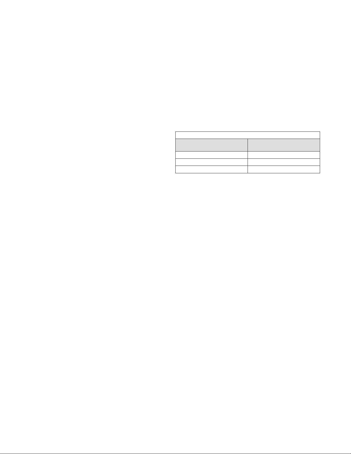
FROST THRESH OLD TEM PER A TURE
IN DOOR RH AT 70oF
20% 0oF
30% 5oF
40% 10oF
FROST THRESH OLD
TEM PER A TURE
Because Energy Recovery Ventilators have a low frost
threshold, frost control options are not necessary in many
climates. Where outdoor temperatures may drop below
the frost threshold during the ERV operational hours,
exhaust only frost control option is available.
Low Am bi ent Kit (Op tional)
Low Ambient Kit turns off the supply blower when outdoor
temperatures fall below the frost threshold. The exhaust
only thermostat set points are field adjustable. Supply fan
operation is automatically restored when the exhaust air
temperature rises above the thermostat set point.
Provisions for introducing make-up air into the building
when the supply blower is off to avoid depressurization
should be considered.
Re cov ery Wheel Mode
On a thermostat call for blower operation in heating,
cooling or continuous blower, the ERW will rotate between
fresh air and exhaust air streams. Both the fresh air and
exhaust air blowers will also be operating to overcome the
air resistance of the ERV.
IX - Sys tem Check
1. Disconnect main power.
2. Turn to "Cont" for blower operation on thermostat
controlled models.
3. Restore power to unit. Observe ERV wheel rotation
and both fresh air and exhaust air blowers while
operating.
Note: If Low ambient kit is used the jumper between
TB37-5 & TB37-6 should be removed. Also if
system check out is being conducted at low
ambient temperatures, technician should be
aware that this kit can cause system not to
operate.
4. Verify that the ERV (3) three phase blower motors are
phased sequentially ensuring correct rotation and
operation.
PAGE 2
Page 3
a - Disconnect power.
b - Reverse any two field power leads to the ERV.
c - Reapply power.
5. Verify that both blower motors are operating under
their full load AMP rating (FLA). The FLA can be found
on each motor and the unit nameplate
A - Re turn Damper Set tings
Manually adjust position of field installed dampers to
balance air flow.
B - Air Flow / Blower Speed Ad just ment
Blower speed selection is accomplished by changing the
sheave setting on both fresh air and exhaust air blowers.
To set ERV for the required air flow (CFM), the external
static pressure applied to the ERV (duct static) must be
known. See the CFM vs External Static Pressure chart for
the appropriate unit to determine the correct blower RPM
for the specified CFM and External Static Pressure.
After blower speed adjustments have been made. Ensure
that when the belt is replaced it is tensioned correctly. The
motor mounting plate can be adjusted to tension the belt. If
using a belt tension checker, adjust the span to the
appropriate setting and check the belt defection force. The
belt deflection force should be between 5-8 lbs or the
lowest tension at which the belt will not slip under peak load
conditions.
1. Disconnect main power to unit before making
adjustment to economizer and/or ERV unit.
2. Replace ERV control access cover.
3. Set thermostat to normal operating position.
4. Restore power to unit.
X - Main te nance
1. All motors use prelubricated sealed bearings; no
further lubrication is necessary.
2. Make visual inspection of motors, belts and wheel
rotating bearings during routine maintenance.
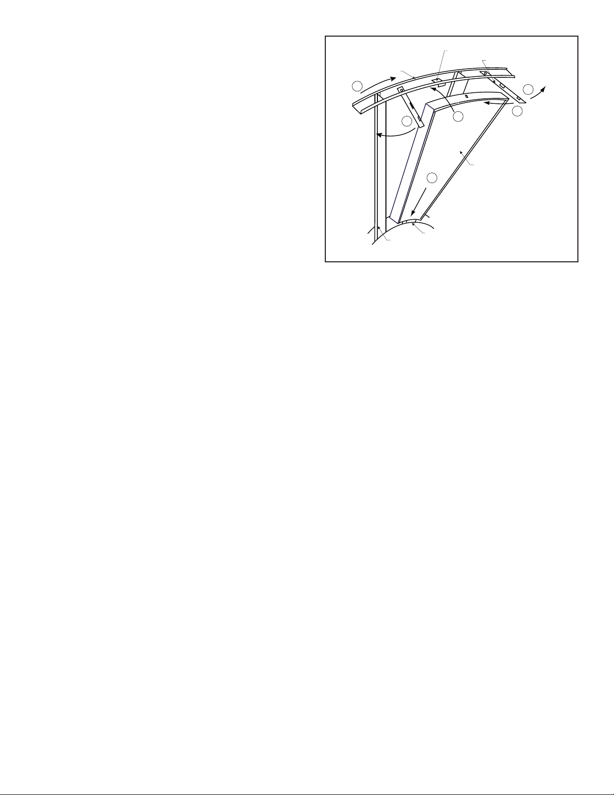
3. Eight pie-shaped segments are seated on stops
between the segment retainer which pivots on the
wheel rim and is secured to the hub and rim of the
wheel. Annual inspection of the self cleaning wheel is
recommended. With power disconnected, remove
ERV access panels (rear) and unplug [J150 & P150]
(Refer to wiring diagram in this instruction
manual). Remove segment and wash with water
and/or mild detergent.
4. To install wheel segments follow steps A through E .
See Figure 1. Reverse procedure for segment
removal.
a. Unlock two segment retainers (one on each side of
the selected segment opening.
b. With the embedded stiffener facing the motor side,
insert the nose of the segment between the hub
plates.
c. Holding segment by the two outer corners, press
the segment towards the center of the wheel and
inwards against the spoke flanges. If hand
pressure does not fully seat the segment, insert
the flat tip of a screw driver between the wheel rim
and outer corners of the segment and apply
WHEEL RIM
E
SPOKE
SEGMENT RETAINER CATCH
D
C
B
HUB
FIGURE 1
SEGMENT RETAINER
A
D
SEGMENT
downward force while guiding the segment into
place.
d. Close and latch each segment retainer under
segment retaining catch.
e. Slowly rotate the wheel 180o. Install the second
segment opposite the first for counterbalance.
Rotate the two installed segments 90o to balance
the wheel while the third segment is installed.
Rotate the wheel 180o again to install the fourth
segment opposite the third. Repeat this sequence
with the remaining four segments.
XI - Pul ley Kit In stal la tion
The units are shipped from the factory at the low static
setting. Pulley kits are available for the medium and high
static settings. To install a pulley kit.
1. Check content of pulley kit, if pulley kit contains:
a. An adjustable sheave and a fixed pitch pulley then
remove belt and both motor and blower pulley
b. An adjustable sheave then remove the motor
pulley.
c. A fixed pitch pulley then remove the blower pulley.
2. Replace pulley(s) with the pulley(s) from pulley kit.
Make sure each pulley is installed with a key. Tighten
the set screw on the pulley(s) to 100 in.lb.
3. Install the belt that came with the pulley kit. Tension
belt as explained in the blower speed adjustment
section.
4. Check the speed of the blower. Adjust the motor
sheave to increase or decrease the speed of the
blower. See blower adjustment section.
PAGE 3
Page 4
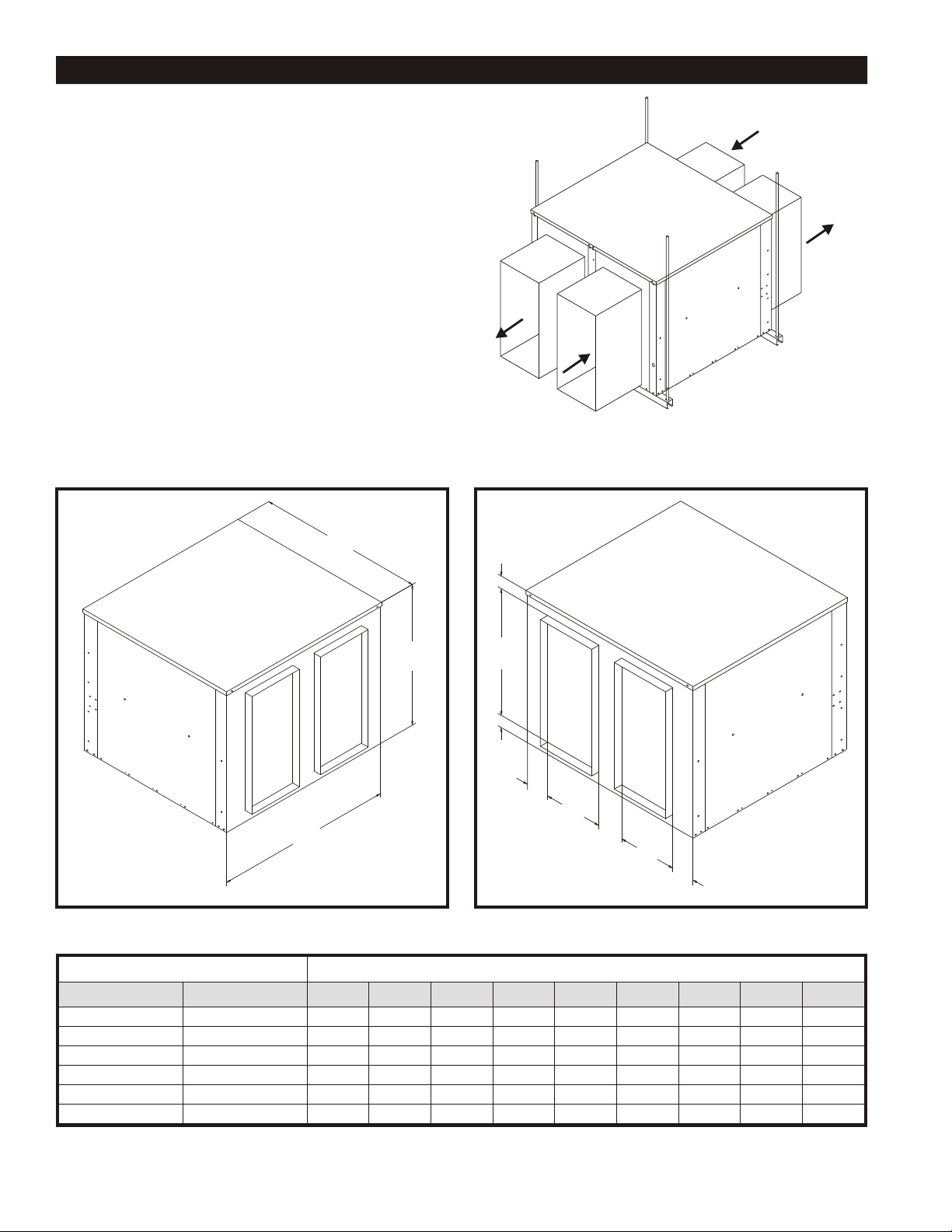
Stand Alone ERV’S For Side by Side In door Application
Fea tures and Notes
1. Stand alone design allows higher levels of outdoor
air to be introduced into the a/c space.
2. Static test ports provided to verify intake and
exhaust CFM.
3. Balancing damper(s) is field provided when
connected to ductwork. System will not operate
properly without balancing damper.
4. See blower performance charts for airflow at various
E.S.P..
5. Filter rack with 2" pleated filters included.
EXHAUST AIR
A
RETURN AIR
TREATED AIR
FRESH AIR
ERV with Hor i zon tal Ductwork
(bal anc ing damper(s) field sup plied)
F
C
B
E
I
H
D
G
D
H
ERV Data Di men sional Data
Size CFM Range A B C D E F G H I
11 300-1100 44.75 32.13 33.50 11.00 27.00 4.00 4.25 2.88 2.50
20 1200-2000 54.38 37.25 37.50 12.00 30.00 1.63 5.13 4.06 1.63
28 1200-2800 52.25 42.62 43.56 14.00 32.00 8.69 5.25 4.25 2.88
36 2000-3600 60.00 46.69 57.37 16.50 39.50 12.00 5.50 4.05 5.88
46 3000-4600 60.00 52.69 57.37 16.50 39.50 12.00 8.69 5.50 5.88
62 4600-6200 72.00 70.88 63.63 19.50 39.50 17.53 14.50 8.70 6.60
PAGE 4
Page 5

A131 Fixed Re lay Board
B26 Mo tor, Ex haust Air
B27 Mo tor, In take Air
B28 Mo tor, Desiccant Wheel
B30 Mo tor, Damper In take (Op tional)
B31 Mo tor, Damper Ex haust (Op tional)
C23 Ca pac i tor, Wheel Mo tor
C25 Ca pac i tor, Ex haust Air
C26 Ca pac i tor, In take Air
F29 Fuse
J48 Jack, Con trol Box (In take Air)
J50 Jack, Con trol Box (Wheel)
J51 Jack, Con trol Box (Ex haust Air)
J56 Jack, Con trol Box (Damper)
J148 Jack, In take Air Mo tor Har ness
J150 Jack, Wheel Mo tor Har ness
COMPONENT CODE
J151 Jack, Ex haust Air Mo tor Har ness
J160 Jack, Damper In take Mo tor Har ness
J161 Jack, Damper Ex haust Mo tor Har ness
K163 Contactor, Ex haust Air Mo tor
K164 Contactor, In take Air Mo tor
MPD-1 Miss ing Pulse De tec tor Board (Op tional)
P48 Plug, In take Air Mo tor Har ness
P50 Plug, Wheel Mo tor Har ness
P51 Plug, Ex haust Air Mo tor Har ness
P56 Plug, Damper Mo tor Har ness
P148 Plug, In take Air Mo tor
P150 Plug, Wheel Mo tor
P151 Plug, Ex haust Air Mo tor
P160 Plug, Damper In take Mo tor Har ness
P161 Plug, Damper Ex haust Mo tor Har ness
RS-1 Ro ta tion Sen sor (Op tional)
S26 Switch, Low Am bi ent (Op tional)
S51 Switch, Door
S52 Switch, Damper In take
S53 Switch, Damper Ex haust
SD Smoke De tec tor (Op tional)
SSJ Cli mate Smart Board (Op tional)
T27 Trans former, Con trol
T28 Trans former, Step-down (Op tional)
TB37 Ter mi nal Block (Low Volt age)
TB39 Ter mi nal Block (Mon i tor ing)
WHL Re lay, Wheel Mo tor
WIRE COLOR
CODE
BK Black
BL Blue
GR Green
GY Gray
OR Orange
PK Pink
RD Red
WT White
YL Yel low
M11-21-2ZERV
PAGE 5
Notes:
1. Re move jumper to in stall field op tional low am bi ent switch.
2. Se lec tive volt age ter mi nal for proper unit volt age
3. Op tional low am bi ent switch.
4. Op tional mo tor ized in take damper.
5. Op tional Stop, Start and Jog Con trol (Cli mate Smart).
6. For en ergy man age ment sys tems con nect +24v to "G"
and com mon 24v to "C".
7. Op tional mo tor ized ex haust damper.
8. Op tional wheel ro ta tion sen sor.
9. Op tional smoke de tec tor.
Page 6

ERV UNIT WIR ING DIAGRAM
."C" ot v42 no mmoc dna
:setoN
.1 .hctiws tn ei bma wol lanoi tpo dleif llat sni ot repmuj evo meR
.2 eg atlov tinu reporp rof la ni mret eg atlov evi tce leS
.3 .hctiws tn ei bma wol lanoi tpO
.4 .repmad eka tni dez iro tom lanoi tpO
.5 .)tramS eta milC( lor tnoC goJ dna tratS ,potS lanoi tpO
.6 "G" ot v42+ tce nnoc sme tsys tne meg anam ygr ene roF
.7 .repmad tsua hxe dez iro tom lanoi tpO
.8 .ro snes noi ta tor leehw lanoi tpO
.9 .ro tce ted ekoms lanoi tpO
PAGE 6
Des ic cant Wheel for Roof top Unit
208- 230V (1 PH)
Unit#: 01-M11-02XX-21
Page 7

A131 Fixed Re lay Board
B26 Mo tor, Ex haust Air
B27 Mo tor, In take Air
B28 Mo tor, Des ic cant Wheel
B30 Mo tor, Damper In take (Op tional)
B31 Mo tor, Damper Ex haust (Op tional)
C23 Ca paci tor, Wheel Mo tor
F29 Fuse
J48 Jack, Con trol Box (In take Air)
J50 Jack, Con trol Box (Wheel)
J51 Jack, Con trol Box (Ex haust Air)
J56 Jack, Con trol Box (Damper)
J148 Jack, In take Air Mo tor Har ness
J150 Jack, W heel Mo tor Har ness
J151 Jack, Ex haust Air Mo tor Har ness
J152 Jack, Trans former (High Volt age)
COMPONENT CODE
J160 Jack, Damper In take Mo tor Har ness
J161 Jack, Damper Ex haust Mo tor Har ness
K163 Contactor, Ex haust Air Mo tor
K164 Contactor, In take Air Mo tor
MPD-1 Miss ing Pulse De tec tor Board (Op tional)
P48
P50
P51 Plug, Ex haust Air Mo tor Har ness
P56 Plug, Damper Mo tor Har ness
P148 Plug, In take Air Mo tor
P150 Plug, Wheel Mo tor
P151 Plug, Ex haust Air Mo tor
P152 Plug, Trans former (High Volt age)
P160 Plug, Damper In take Mo tor Harness
Plug, In take Air Mo tor Har ness
Plug, Wheel Mo tor Har ness
P161 Plug, Damper Ex haust Mo tor Harness
RS-1 Ro ta tion Sen sor (Op tional)
S26 Switch, Low Am bi ent (Op tional)
S51 Switch, Door
S52 Switch, Damper Intake
S53 Switch, Damper Exhaust
SD Smoke De tec tor (Op tional)
SSJ Cli mate Smart Board (Op tional)
T27 Trans former, Con trol
T28 Trans former, Step- down (Op tional)
TB37 Ter mi nal Block (Low Volt age)
TB39 Ter mi nal Block (Mon i tor ing)
WHL Re lay, Wheel Motor
WIRE COLOR
CODE
BK Black
BL Blue
GR Green
GY Gray
OR Orange
PK Pink
RD Red
WT White
YL Yel low
M11-M62-2ZERV
Notes:
1. Re move jumper to in stall field op tional low am bi ent switch.
2. Step-down trans former as sem bly for 460/575 volt units.
3. Se lec tive volt age ter mi nal for proper unit volt age
4. Op tional low am bi ent switch.
5. Op tional mo tor ized in take damper.
6. Op tional Stop, Start and Jog Con trol (Cli mate Smart).
7. For en ergy man age ment sys tems con nect +24v to "G" and com mon 24v to "C".
8. Op tional mo tor ized ex haust damper.
9. Op tional wheel ro ta tion sen sor.
10. Op tional smoke de tec tor.
PAGE 7
Page 8

ERV UNIT WIR ING DIAGRAM
:setoN
.1 .hctiws tn ei bma wol lanoi tpo dleif llat sni ot repmuj evo meR
.2 .stinu tlov 575/064 rof yl bme ssa remro fsnart nwod-petS
.3 eg atlov tinu reporp rof la ni mret eg atlov evi tce leS
.4 .hctiws tn ei bma wol lanoi tpO
.5 .repmad eka tni dez iro tom lanoi tpO
.6 .)tramS eta milC( lor tnoC goJ dna tratS ,potS lanoi tpO
.01 .ro tce ted ekoms lanoi tpO
.7 ."C" ot v42 no mmoc dna "G" ot v42+ tce nnoc sme tsys tne meg anam ygr ene roF
.8 .repmad tsua hxe dez iro tom lanoi tpO
.9 .ro snes noi ta tor leehw lanoi tpO
PAGE 8
Des ic cant Wheel for Roof top Unit
208- 230/460/575V (3 PH)
Unit#: 01-M11-M62-02XX-23 thru -43
Page 9

SUP PLY
CFM
EXHAUST
CFM
Blower RPM for XAWS11
Mist Elimi na tor Fil ter in In take Hood (1.5HP)
Ex ter nal Static Pres sure (in wa ter)
0 0.25 0.5 0.75 1 1.25 1.5
300 N/A N/A 1075 1280 1390 1535 1635
500 N/A 1065 1275 1355 1505 1615 1670
700 1060 1270 1370 1525 1610 1660 1790
900 1310 1455 1520 1605 1655 1820 1960
1100 1445 1515 1625 1725 1815 1955 2035
Ba ro met ric Hood, 2" Pleated Fil ters (1.5HP)
Ex ter nal Static Pres sure (in wa ter)
0 0.25 0.5 0.75 1 1.25 1.5
300 N/A 1075 1180 1290 1445 1565 1645
500 N/A 1170 1285 1375 1470 1605 1725
700 1065 1280 1370 1465 1600 1680 1800
900 1255 1360 1460 1590 1675 1755 1865
1100 1445 1455 1585 1670 1750 1860 1935
Notes:
1. Drive losses included in the above tables.
2. Performance can vary depending on ambient conditions
3. Blower RPMs are for reference only
Blower RPM for XAWS20
SUP PLY
Mist Elimi na tor Fil ter in In take Hood (2HP)
0 0.25 0.5 0.75 1 1.25 1.5
1200 1100 1225 1315 1405 1440 1695 1725
1400 1220 1275 1400 1480 1620 1730 1790
CFM
EXHAUST
CFM
1600 1225 1345 1475 1615 1715 1775 1890
1800 1335 1465 1610 1710 1765 1880 1930
2000 1380 1585 1680 1755 1815 1920 N/A
Ba ro met ric Hood, 2" Pleated Fil ters (2HP)
0 0.25 0.5 0.75 1 1.25 1.5
1200 1045 1170 1380 1475 1635 1720 1805
1400 1115 1330 1470 1570 1725 1745 1850
1600 1320 1460 1565 1680 1790 1840 1940
1800 1415 1560 1725 1780 1885 1930 2045
2000 1490 1660 1770 1875 1920 1985 N/A
RPM Range
Low 1000-1300 Stan dard Unit
Me dium 1300-1750 Op tional Kit
High 1750-2200 Op tional Kit
Ex ter nal Static Pres sure (in wa ter)
Ex ter nal Static Pres sure (in wa ter)
Notes:
1. Drive losses included in the above tables.
2. Performance can vary depending on ambient conditions
3. Blower RPMs are for reference only
RPM Range
Low 1000-1300 Stan dard Unit
Me dium 1300-1700 Op tional Kit
High 1700-2080 Op tional Kit
PAGE 9
Page 10

SUP PLY
CFM
EXHAUST
CFM
Blower RPM for XAWS28
Mist Elimi na tor Fil ter in In take Hood (3HP)
Ex ter nal Static Pres sure (in wa ter)
0 0.25 0.5 0.75 1 1.25 1.5
1200 N/A N/A 985 1115 1255 1390 1445
1600 N/A 975 1090 1190 1320 1320 1525
2000 960 1085 1185 1315 1410 1410 1550
2400 1080 1240 1310 1405 1485 1485 1650
2800 1230 1395 1505 1535 1595 1595 1775
Ba ro met ric Hood, 2" Pleated Fil ters (3HP)
Ex ter nal Static Pres sure (in wa ter)
0 0.25 0.5 0.75 1 1.25 1.5
1200 N/A N/A 1050 1210 1315 1375 1465
1600 N/A 1020 1200 1285 1365 1465 1545
2000 1010 1190 1320 1355 1540 1580 1660
2400 1155 1315 1425 1545 1660 1735 1785
2800 1290 1450 1600 1725 1755 1825 1880
Notes:
1. Drive losses included in the above tables.
2. Performance can vary depending on ambient conditions
3. Blower RPMs are for reference only
Blower RPM for XAWS36
SUP PLY
Mist Elimi na tor Fil ter in In take Hood (3HP)
0 0.25 0.5 0.75 1 1.25 1.5
2000 820 930 1015 1095 1160 1245 1315
2400 920 1010 1090 1155 1240 1305 1405
CFM
EXHAUST
CFM
2800 1000 1085 1150 1235 1295 1410 1500
3200 1130 1200 1260 1395 1430 1495 1565
3600 1190 1385 1420 1455 1510 N/A N/A
Ba ro met ric Hood, 2" Pleated Fil ters (3HP)
0 0.25 0.5 0.75 1 1.25 1.5
2000 780 890 970 1065 1130 1235 1275
2400 885 965 1060 1125 1230 1270 1340
2800 945 1055 1120 1225 1265 1355 1405
3200 1050 1135 1255 1325 1350 1415 1460
3600 1125 1250 1305 1340 1415 N/A N/A
RPM Range
Low 950-1320 Stan dard Unit
Me dium 1325-1565 Op tional Kit
High 1570-1880 Op tional Kit
Ex ter nal Static Pres sure (in wa ter)
Ex ter nal Static Pres sure (in wa ter)
Notes:
1. Drive losses included in the above tables.
2. Performance can vary depending on ambient conditions
3. Blower RPMs are for reference only
RPM Range
Low 700-1025 Stan dard Unit
Me dium 1030-1305 Op tional Kit
High 1325-1575 Op tional Kit
PAGE 10
Page 11

SUP PLY
CFM
EXHAUST
CFM
Blower RPM for XAWS46
Mist Elimi na tor Fil ter in In take Hood (5HP)
Ex ter nal Static Pres sure (in wa ter)
0 0.25 0.5 0.75 1 1.25 1.5
3000 925 1035 1110 1140 1235 1315 1350
3400 1030 1120 1185 1225 1310 1345 1385
3800 1100 1150 1240 1335 1385 1420 1455
4200 1165 1245 1375 1435 1460 1505 1550
4600 1230 1315 1335 1470 1525 1585 1655
Ba ro met ric Hood, 2" Pleated Fil ters (5HP)
Ex ter nal Static Pres sure (in wa ter)
0 0.25 0.5 0.75 1 1.25 1.5
3000 985 1085 1155 1280 1325 1370 1440
3400 1060 1150 1270 1320 1365 1430 1480
3800 1145 1265 1335 1400 1450 1475 1505
4200 1240 1330 1375 1460 1470 1515 1560
4600 1305 1400 1420 1485 1525 1550 1650
Notes:
1. Drive losses included in the above tables.
2. Performance can vary depending on ambient conditions
3. Blower RPMs are for reference only
Blower RPM for XAWS62
SUP PLY
Mist Elimi na tor Fil ter in In take Hood (5HP)
0 0.25 0.5 0.75 1 1.25 1.5
4600 820 910 990 1020 1135 1165 1225
5000 885 965 1040 1100 1160 1225 1280
CFM
EXHAUST
CFM
5400 910 1000 1095 1155 1215 1275 N/A
5800 960 1060 1145 1205 1265 1290 N/A
6200 1020 1110 1195 1255 1275 N/A N/A
Ba ro met ric Hood, 2" Pleated Fil ters (5HP)
0 0.25 0.5 0.75 1 1.25 1.5
4600 875 935 1000 1025 1140 1175 1190
5000 910 975 1040 1130 1190 1200 1280
5400 945 1015 1095 1150 1230 1275 N/A
5800 990 1060 1125 1175 1265 N/A N/A
6200 1010 1110 1195 1200 N/A N/A N/A
RPM Range
Low 780- 1020 Stan dard Unit
Me dium 1000- 1315 Op tional Kit
High 1315- 1700 Op tional Kit
Ex ter nal Static Pres sure (in wa ter)
Ex ter nal Static Pres sure (in wa ter)
Notes:
1. Drive losses included in the above tables.
2. Performance can vary depending on ambient conditions
3. Blower RPMs are for reference only
RPM Range
Low 700-900 Stan dard Unit
Me dium 900-1100 Op tional Kit
High 1100-1300 Op tional Kit
PAGE 11
Page 12

START UP INFORMATION SHEET
VOLT AGE - ERV UNIT
In com ing Volt age L1-L2 L1-L3 L2-L3
Run ning Volt age L1-L2 L 1-L3 L2-L3
Sec ond ary Volt age C (black) to G (green) Volts*
C (black) to W (white) Volts*
* With ther mo stat call ing.
AM PER AGE - ERV MO TORS
In take Mo tor: Nom i nal HP Rated Amps Run ning Amps
Ex haust Mo tor: Nom i nal HP Rated Amps Run ning Amps
Wheel Mo tor: Nom i nal HP Rated Amps Run ning Amps
AIR FLOW
In take De sign CFM Pres sure Drop Cal cu lated CFM
Ex haust De sign CFM Pres sure Drop Cal cu lated CFM
Amb. db Temp Re turn Air db Temp* Tem pered Air db Temp*
Amb. wb Temp Re turn Air wb Temp* Tem pered Air wbTemp*
* Mea sure af ter 15 min utes of run time
IN STAL LA TION CHECK LIST
ERV Model # Se rial #
Owner Owner Phone #
Owner Ad dress
In stall ing Con trac tor Start Up Me chanic
q Inspect the unit for transit damage and report any damage on the carrier’s freight bill.
q Check model number to insure it matches the job requirements.
q Install field accessories and unit adapter panels as required. Follow accessory and unit installation manuals.
q Verify field wiring, including the wiring to any accessories.
q Check all multi-tap transformers, to insure they are set to the proper incoming voltage.
q Verify correct belt tension, as well as the belt/pulley alignment. Tighten if needed.
q Prior to energizing the unit, inspect all the electrical connections.
q Power the unit. Bump the motor contactor to check rotation. Three phase motors are synchronized at the
factory. If blower motor fans are running backwards, de-energize power to the unit, then swap two of the three
incoming electrical lines to obtain proper phasing. Re-check.
q Perform all start up procedures outlined in the installation manual shipped with the unit.
q Fill in the Start Up Information as outlined on the opposite side of this sheet.
q Provide owner with information packet. Explain the thermostat and unit operation.
1-800-695-1901; www.ReznorHVAC.com
©2014 Reznor, LLC. All rights reserved. Printed in U.S.A.
Reznor® is registered in at least the United States.
All other marks are the property of their respective organizations.
 Loading...