

Page 1
NATURAL GAS HIGH ALTITUDE CONVERSION INSTRUCTIONS
Applies to : Gas-Fired, Tubular, Radiant,
Low-Intensity Infrared Heater
Models VPS, VPT, VCS, VCT
Part no. 270687
Page 2
Section 1 …………VPS Three Fixing Fan.
Section 2 ……… VPS Four Fixing Fan.
Section 3 ……… VPT, VCS/T Three Fixing Fan.
Section 4 …………VPT, VCS/T Four Fixing Fan.
VPS Model
Fresh Air Inlet Plate Type
Size
VPS 3 Hole
VPS 4 Hole
VPT/VCT 3 hole
VPT/VCT 4 hole
VCS 3 hole
VCS 4 hole
60 80 100 125 150 170 200
* * * * * *
* * * * *
* *
* * * * * *
Fan orifice
plate
*
*
Size 60 80 100 125 150 170 200
Remove plate with ‘X’
Qty. of holes (10mm)
Add plate with ‘X’ Qty. of
holes (10mm)
8 7 8 11 11 15 18
9 9 10 14 15 26 22
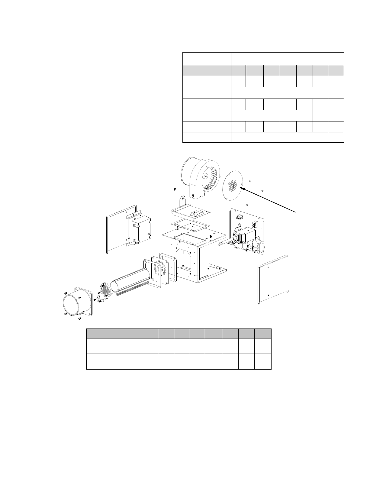
There are two types of combustion fan, one with three orifice plate fixings and one with
four orifice plate fixings. Follow the relevant procedure for the type of fan fitted to the
appliance being converted.
2
Page 3
Section 1
Three Fixing Fan Procedure
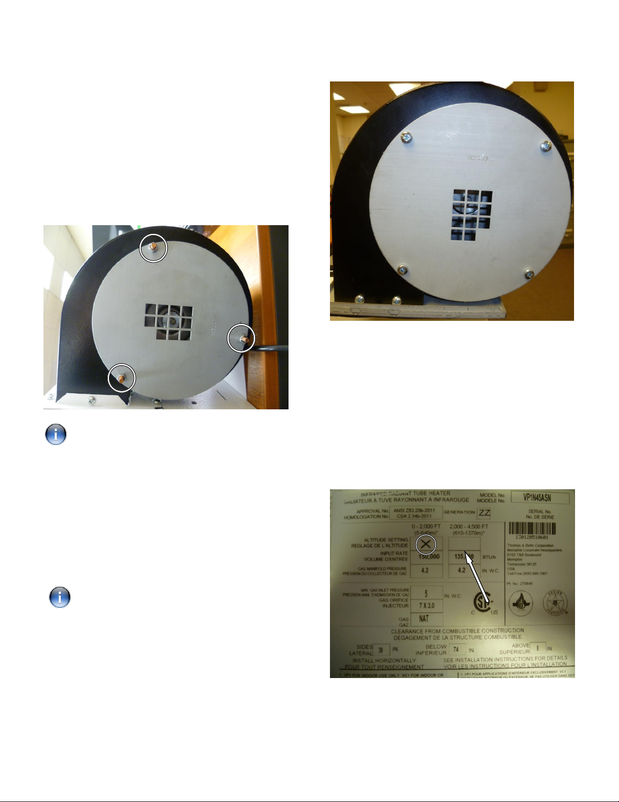
Step 1: Remove the nuts securing the fan orifice
plate with an 8mm wrench. Remove the fan orifice
plate from the threaded studs.
Step 2: Fit the new high altitude fan orifice plate onto
the fan studs. Re-fit the 3 x 8mm nuts, using the
wrench to tighten.
Take care not to cross thread the fasteners.
Final Step
Ensure that when converted for use at high altitude,
the data label is amended. Cover the previous
‘X’ (highlighted in a circle) with a blank label.
The altitude conversion can be identified with
another ‘X’ in the blank box indicated by the arrow.
Ensure a permanent marker is used.
Section 2
Four Fixing Fan Plate Procedure
Step 1: Using a No.2 crosshead screwdriver
remove the four screws securing the fan orifice
plate . Remove plate.
Step 2: Fit the new high altitude fan orifice plate and
secure with the same four screws.
Take care not to cross thread the screw
fixings.
VPS Model Data Label
3
Page 4
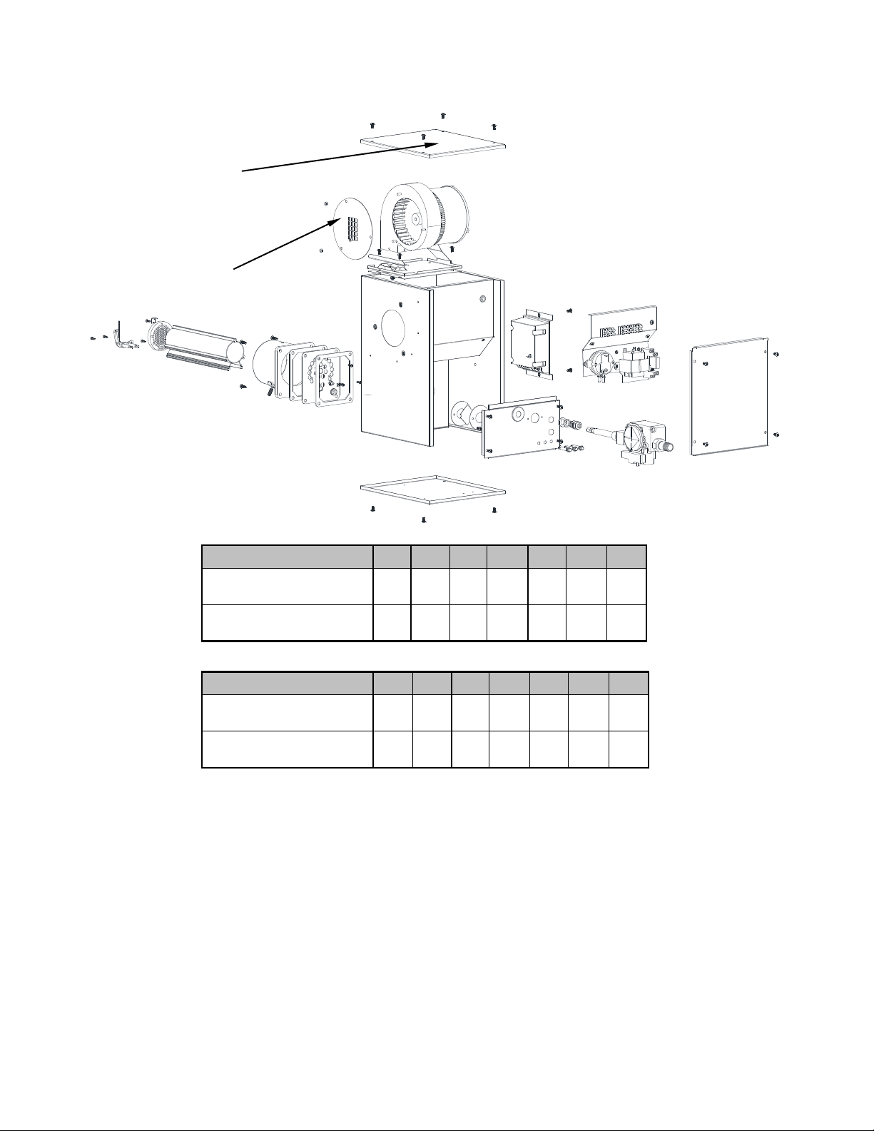
Burner Top Cover
Fan Orifice Plate
Remove plate with ‘X’
Add plate with ‘X’ Qty. of
Size (VCS only)
Qty. of holes (10mm)
holes (10mm)
VPT, VCS/T Models
60 80 100 125 150 170 200
8 7 8 11 11 15 18
9 9 10 14 15 26 22
Size (VPT/VCT only)
Remove plate with ‘X’
Qty. of holes (10mm)
Add plate with ‘X’ Qty. of
holes (10mm)
60 80 100 125 150 170 200
6 10 8 11 15 11 18
9 11 11 14 18 18 22
There are two types of combustion fan. One with three orifice plate fixings and one
with four orifice plate fixings. Follow the relevant procedure for the type of fan fitted to
the appliance being converted.
4
Page 5

On VPT, VCS/T models, remove the top cover of
the burner using a No.2 cross headed screwdriver to
expose the combustion fan. .
Section 3
Three Fixing Fan Procedure
Step 1: Remove the four screws arrowed, three of
these cannot be seen in the picture. Lift out the fan
assembly.
Step 3: Fit the new high altitude fan orifice plate onto
the fan studs. Re-fit the 3 x 8mm nuts, using the
wrench to tighten.
Step 4: Refit the fan and the lid of the burner.
Section 4
Four Fixing Fan Procedure
Step 1: Remove the four screws arrowed, three of
these cannot be seen in the picture. Lift out the fan
assembly.
Step 2: Using an 8mm wrench remove the nuts
securing the fan orifice plate. Remove the fan orifice
plate from the threaded studs.
5
Page 6

Step 2: Using a no.2 crosshead screwdriver remove
the four screws securing the fan orifice plate and
remove.
VPT, VCT Model Data Label
VCS Model Data Label
Step 3: Fit the new high altitude fan orifice plate and
secure with the same four screws.
Take care not to cross thread the screw
fixings.
Step 4: Refit the fan and the lid of the burner.
Final Step
Ensure that when converted for use at high altitude,
the data label is amended. Cover the previous
‘X’ (highlighted in a circle) with a blank label.
The altitude conversion can be identified with
another ‘X’ in the blank box indicated by the arrow.
Ensure a permanent marker is used.
6
Page 7

Natural Gas High Altitude Conversion Kits
Models Natural Gas High Altitude Conversion Kit 270630
VPS 60
VCS 60
VPT 60
VCT 60
VPS 80
VCS80
Models Natural Gas High Altitude Conversion Kit 270631
Quantity Description Part No.
1 Natural Gas High altitude conversion manual VC/VP 270687
1 Blown fan orifice plate to suit 2576T, 9 x 10mm square holes 269924
VPT 80
VCT 80
VPS 100
VCS 100
VPT 100
VCT 100
Models Natural Gas High Altitude Conversion Kit 270632
VPS 125
VCS 125
VPT 125
VCT 125
Models Natural Gas High Altitude Conversion Kit 270633
VPS 150
VCS 150
VPT 150
VCT 150
Quantity Description Part No.
1 Natural Gas High altitude conversion manual VC/VP 270687
1 Blown fan orifice plate to suit 2576T, 10 x 10mm square holes 269925
1 Blown fan orifice plate to suit 2576T, 11 x 10mm square holes 269926
Quantity Description Part No.
1 Natural Gas High altitude conversion manual VC/VP 270687
1 Blown fan orifice plate to suit 2576T, 14 x 10mm square holes 269929
Quantity Description Part No.
1 Natural Gas High altitude conversion manual VC/VP 270687
1 Blown fan orifice plate to suit 2576T, 15 x 10mm square holes 269930
1 Blown fan orifice plate to suit 2576T, 18 x 10mm square holes 269931
Models Natural Gas High Altitude Conversion Kit 270634
VPS 170
VCS 170
VPT 170
VCT 170
Models Natural Gas High Altitude Conversion Kit 270635
VPS 200
VCS 200
VPT 200
VCT 200
Quantity Description Part No.
1 Natural Gas High altitude conversion manual VC/VP 270687
1 Blown fan orifice plate to suit 2576T, 9 x 10mm square holes 269924
Quantity Description Part No.
1 Natural Gas High altitude conversion manual VC/VP 270687
1 Blown fan orifice plate to suit 2576T, 26 x 10mm square holes 269933
1 Blown fan orifice plate to suit 2560-1, 18 x 10mm square holes 269938
7
Page 8

Orifice Pressure Adjustment (VPS/VCS)
USA Natural Gas 2001– 4000 ft (611-1220m)
Size
“WC
mbar
USA Natural Gas 4001– 6000 ft (1221-1829m)
Size
“WC
mbar
USA
Size 60 80 100 125 150 170 200
“WC 3.9 3.2 3.2 3.8 3.9 3.1 3.2
mbar 9.7 8.0 8.0 9.5 9.7 7.7 8.0
60 80 100 125 150 170 200
4.0 3.3 3.3 3.9 4.0 3.2 3.3
10.0 8.2 8.2 9.7 10.0 8.0 8.2
60 80 100 125 150 170 200
4.0 3.3 3.3 3.9 4.0 3.2 3.3
10.0 8.2 8.2 9.7 10.0 8.0 8.2
Natural Gas 6001– 10000 ft (1830-3048m)
CANADA Natural Gas 2001– 4500 ft (611-1370m)
Size
“WC
mbar
60 80 100 125 150 170 200
4.0 3.3 3.3 3.9 4.0 3.2 3.3
10.0 8.2 8.2 9.7 10.0 8.0 8.2
8
Page 9

Orifice Pressure Adjustment (VPT/VCT)
USA Natural Gas 2001– 4000 ft (611-1220m)
Size
“WC Hi
mbar Hi
“WC Lo
mbar Lo
USA Natural Gas 4001– 6000 ft (1221-1829m)
Size
“WC Hi
mbar Hi
“WC Lo
mbar Lo
60 80 100 125 150 170 200
4.1 3.7 4.7 4.3 4.2 3.8 3.3
10.2 9.2 11.7 10.7 10.5 9.5 8.2
2.3 2.1 2.0 2.5 2.0 2.2 2.0
5.7 5.2 5.0 6.2 5.0 5.5 5.0
60 80 100 125 150 170 200
4.1 3.7 4.7 4.3 4.2 3.8 3.3
10.2 9.2 11.7 10.7 10.5 9.5 8.2
2.3 2.1 2.0 2.5 2.0 2.2 2.0
5.7 5.2 5.0 6.2 5.0 5.5 5.0
USA Natural Gas 6001– 10000 ft (1830-3048m)
Size
“WC Hi
mbar Hi
“WC Lo
mbar Lo
CANADA Natural Gas 2001– 4500 ft (611-1371m)
Size
“WC Hi
mbar Hi
“WC Lo
mbar Lo
60 80 100 125 150 170 200
4.0 3.6 4.6 4.2 4.1 3.7 3.2
10.0 9.0 11.5 10.5 10.2 9.2 8.0
2.2 2.0 1.9 2.4 1.9 2.1 1.9
5.5 5.0 4.7 6.0 4.7 5.2 4.7
60 80 100 125 150 170 200
4.1 3.7 4.7 4.3 4.2 3.8 3.3
10.2 9.2 11.7 10.7 10.5 9.5 8.2
2.3 2.1 2.0 2.5 2.0 2.2 2.0
5.7 5.2 5.0 6.2 5.0 5.5 5.0
9
Page 10

10 11 12
Page 11

Page 12

Specifications & illustrations subject to change without notice or incurring obligations.
©2014 All rights reserved.
All marks are the property of their respective organizations.
O’Fallon, MO | Printed in U.S.A. (09/14)
244E-0914 Form I-VC/VP-HA
 Loading...