

Page 1
Revision: P-UEAS (11-18) PN269865R7
Supersedes: P-UEAS (03-18) PN269865R6
REPLACEMENT PARTS FOR HIGH-EFFICIENCY, LOW-STATIC
UNIT HEATERS
MODEL UEAS
TABLE OF CONTENTS
REFERENCES ..............................................................................................................................................................................2
RATING PLATE .............................................................................................................................................................................2
SERIAL NUMBERS ......................................................................................................................................................................3
ELECTRICAL COMPONENTS .....................................................................................................................................................4
FLUE WRAPPER AND VENTER COMPONENTS .......................................................................................................................5
FAN AND MOTOR COMPONENTS ..............................................................................................................................................7
GAS CONVERSION KITS ............................................................................................................................................................7
BURNER ASSEMBLY COMPONENTS ........................................................................................................................................8
MANUAL SHUTOFF VALVE .........................................................................................................................................................9
HEAT EXCHANGER COMPONENTS ..........................................................................................................................................9
CONDENSATE DRAIN KIT (PN 235368) FOR REPLACEMENT HEAT EXCHANGERS ...................................................10
VENT/COMBUSTION AIR COMPONENTS ...............................................................................................................................10
LOUVER ASSEMBLY COMPONENTS ......................................................................................................................................11
NOZZLE COMPONENTS ...........................................................................................................................................................12
HANGER KIT COMPONENTS ...................................................................................................................................................13
THERMOSTAT COMPONENTS ...............................................................................................................................................13
CABINET COMPONENTS ..........................................................................................................................................................14
IMPORTANT
1. Always include complete model and serial number so that any specification change can be considered for parts replacement.
It can save time and expense.
2. In keeping with our policy of continuous product improvement, we reserve the right to alter any information shown here.
Specifications are subject to change without notice.
3. We reserve the right to substitute functional replacements.
4. Order by Part Number (PN) not by option designation.
Page 2
REFERENCES
Related Technical Manuals Available from Factory Distributor
Type Form PN
Installation/operation/maintenance I-UEAS 221232
Ignition system and gas valve replacement
parts
D300522 P-VALVES 263995
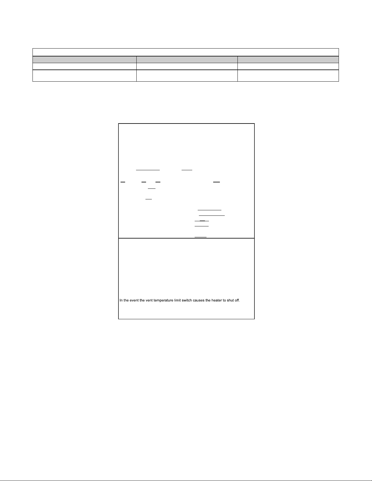
RATING PLATE
SAMPLE RATING PLATE AND KEY
MERCER, PA. USA 16137
MADE IN MEXICO
SEPARATED COMBUSTION SYSTEM UNIT HEATER
CATEGORY IV
ANSI Z83.8 CSA 2.6 UNIT HEATER
MODEL [ B ] [ C ]
SERIAL NO.
[ D ] VOLTS [ D ] PH [ D ] HZ MAXIMUM TOTAL INPUT [ D ] AMPS
TYPE OF GAS: [ E ]
FOR USE AT 0-2000 FEET, 0-610 METERS OF ALTITUDE.
ORIFICE SIZE [ F ] DRILL
NORMAL INPUT
THERMAL OUTPUT CAPACITY [ L ] BTU/HR
MINIMUM INPUT
NORMAL MANIFOLD PRESSURE [ G ] IN.W.C.
MIN. PERMISSIBLE GAS SUPPLY PRESSURE
FOR PURPOSE OF INPUT ADJUSTMENT.
CLEARANCES TO COMBUSTIBLE CONSTRUCTION: TOP-4", FLUE
CONNECTION-0", CONTROL SIDE-18", OPP. SIDE-2", BOTTOM-1", FRONT-36"
FOR ALTERNATE INSTALLATIONS USE THE LATEST EDITIONS OF THE
APPROPRIATE STANDARD LISTED BELOW:
FOR AIRCRAFT HANGARS USE STANDARD ANSI/NFPA 409
FOR PARKING STRUCTURES USE STANDARD ANSI/NFPA 88A
FOR REPAIR GARAGES USE STANDARD ANSI/NFPA 88B
THIS UNIT IS NOT FOR USE WITH DUCTS.
THIS UNIT IS NOT FOR USE WITH FILTERS.
CONSTRUCTION WALL THICKNESS FOR PURPOSE OF VENTING:
1" MIN., 48" MAX.
SEA LEVEL
[ J ] BTU/HR
[ M ] BTU/HR
[ H ] IN.W.C.
Determine and correct the cause. Failure to do so could result in personal
injury or death. To reset, depress the button on the sensor located on the side
of the venter housing.
B = Model number
C = Date of manufacture (month and year)
D = Volts/phase/Hertz/input amps
E = Fuel type (natural gas or propane)
F = Orifice size
G = Normal manifold pressure (IN WC)
H = Minimum gas supply pressure (IN WC)
J = Normal BTUh input (sea level)
L = Thermal output BTUh (sea level)
M = Minimum BTUh input (sea level)
2
P-UEAS (11-18) PN269865R7
Page 3
SERIAL NUMBERS
Serial number format changed in June of 2015. Use the following information to decode system serial numbers:
DECODING A SYSTEM SERIAL NUMBER FOR ALL MODELS BEFORE JUNE 2015
Serial No. Sample: BLK 79 6E N 00000
Elements Key No.: 1 I 2 I 3 I 4 I 5
Key:
1 = Date code (refer to Table 1)
2 = Type of ignition system
3 = Type of gas valve
4 = Gas (N = natural; L = propane)
5 = Consecutive number
Prex Key:
E = E3 (409) stainless steel heat exchanger
DECODING A SYSTEM SERIAL NUMBER FOR ALL MODELS AFTER MAY 2015
Serial No. Sample: BOG 3060 00000
Elements Key No.: 1 | 2 | 3
Key:
1 = Date code (refer to Table 1)
2 = Plant of manufacture (3060 = Mercer; 3062 = Monterrey)
3 = Consecutive number
Year
2007
2008
2009
2010
2011
2012
2013
2014
2015
2016
2017
2018
2019
2020
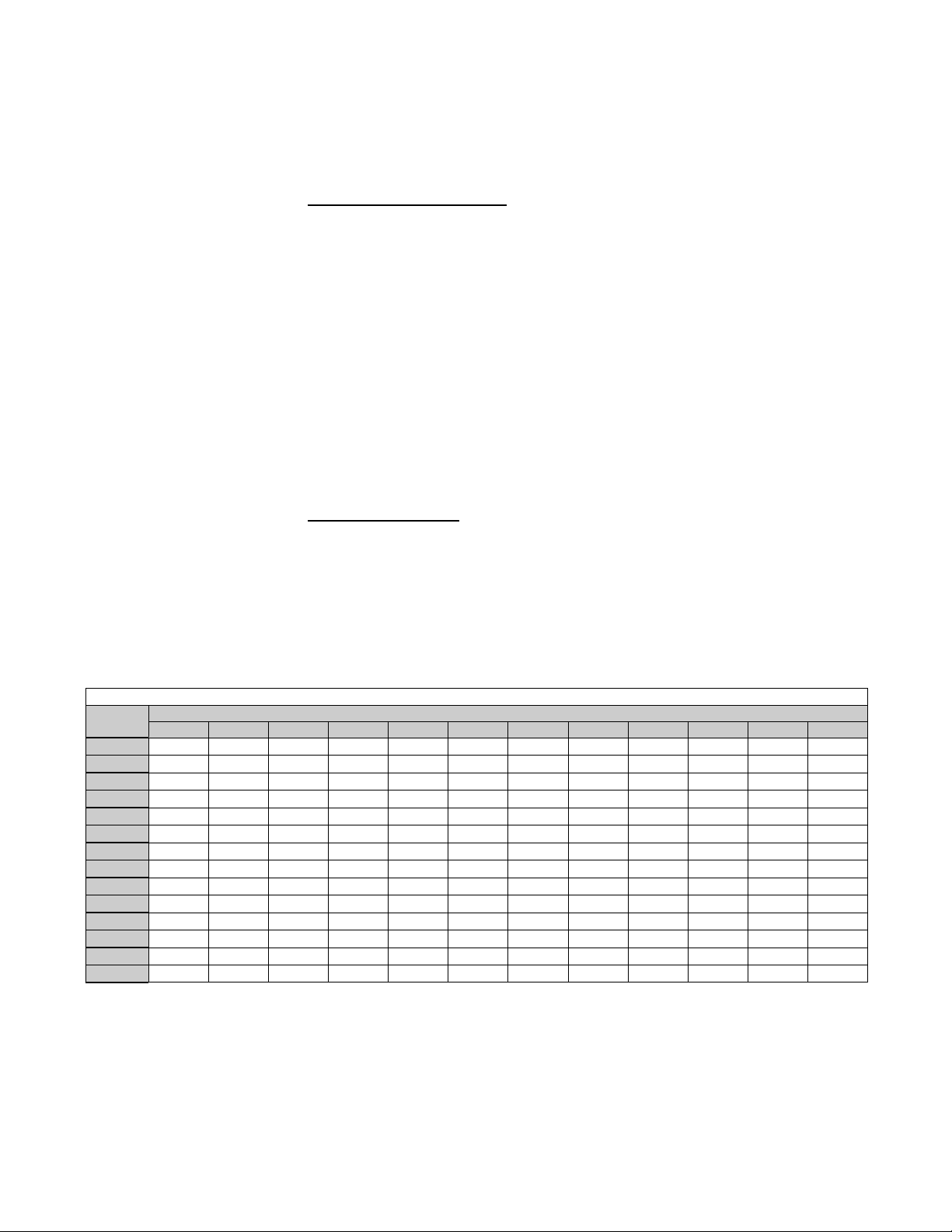
Table 1. Serial Number Date Codes (Month and Year)
Month
JAN FEB MAR APR MAY JUN JUL AUG SEP OCT NOV DEC
BGA BGB BGC BGD BGE BGF BGG BGH BGI BGJ BGK BGL
BHA BHB BHC BHD BHE BHF BHG BHH BHI BHJ BHK BHL
BIA BIB BIC BID BIE BIF BIG BIH BII BIJ BIK BIL
BJA BJB BJC BJD BJE BJF BJG BJH BJI BJJ BJK BJL
BKA BKB BKC BKD BKE BKF BKG BKH BKI BKJ BKK BKL
BLA BLB BLC BLD BLE BLF BLG BLH BLI BLJ BLK BLL
BMA BMB BMC BMD BME BMF BMG BMH BMI BMJ BMK BML
BNA BNB BNC BND BNE BNF BNG BNH BNI BNJ BNK BNL
BOA BOB BOC BOD BOE BOF BOG BOH BOI BOJ BOK BOL
BPA BPB BPC BPD BPE BPF BPG BPH BPI BPJ BPK BPL
BQA BQB BQC BQD BQE BQF BQG BQH BQI BQJ BQK BQL
BRA BRB BRC BRD BRE BRF BRG BRH BRI BRJ BRK BRL
BSA BSB BSC BSD BSE BSF BSG BSH BSI BSJ BSK BSL
BTA BTB BTC BTD BTE BTF BTG BTH BTI BTJ BTK BTL
P-UEAS (11-18) PN269865R7
3
Page 4
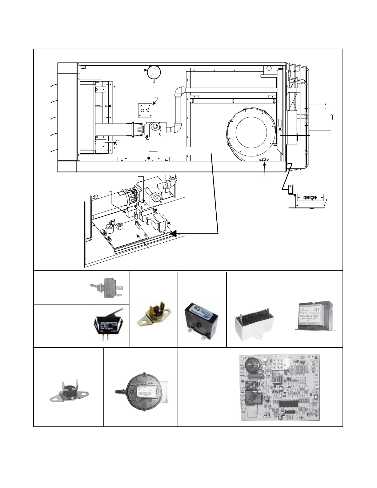
ELECTRICAL COMPONENTS
1 - Disconnect
Switch
5 - Pressure
Switch
4 - High Temperature
ylbmessA renruB
Limit Control
Flame
Sensor
Fan
Motor
Code 1:
Disconnect
Switch
Code 2: Door
Switch
6 - Time Delay Relay
7 - Venter
Motor Capacitor
Ignitor
Code 3: Vent
Temperature
Limit Switch
Gas Valve
Control Panel Assembly
8 - Fan Motor Capacitor
9 - Transformer
10 - DSI Integrated Control
Module (Circuit Board)
Code 6:
Time
Delay
Relay
Venter
3 - Vent
Temperature
Limit Switch
for connecting thermostat
Codes 7 and 8:
Venter
Motor
Capacitor
2 - Door
Switch
11 - Te rminal Board
Code 9:
Transformer
Code 4: High
Temperature Limit
Switch
4
Code 5: Pressure
Switch
Code 10:
DSI Control
Module,
Integrated
Circuit Board
Figure 1. Electrical Components (Refer to Table 2)
P-UEAS (11-18) PN269865R7
Page 5
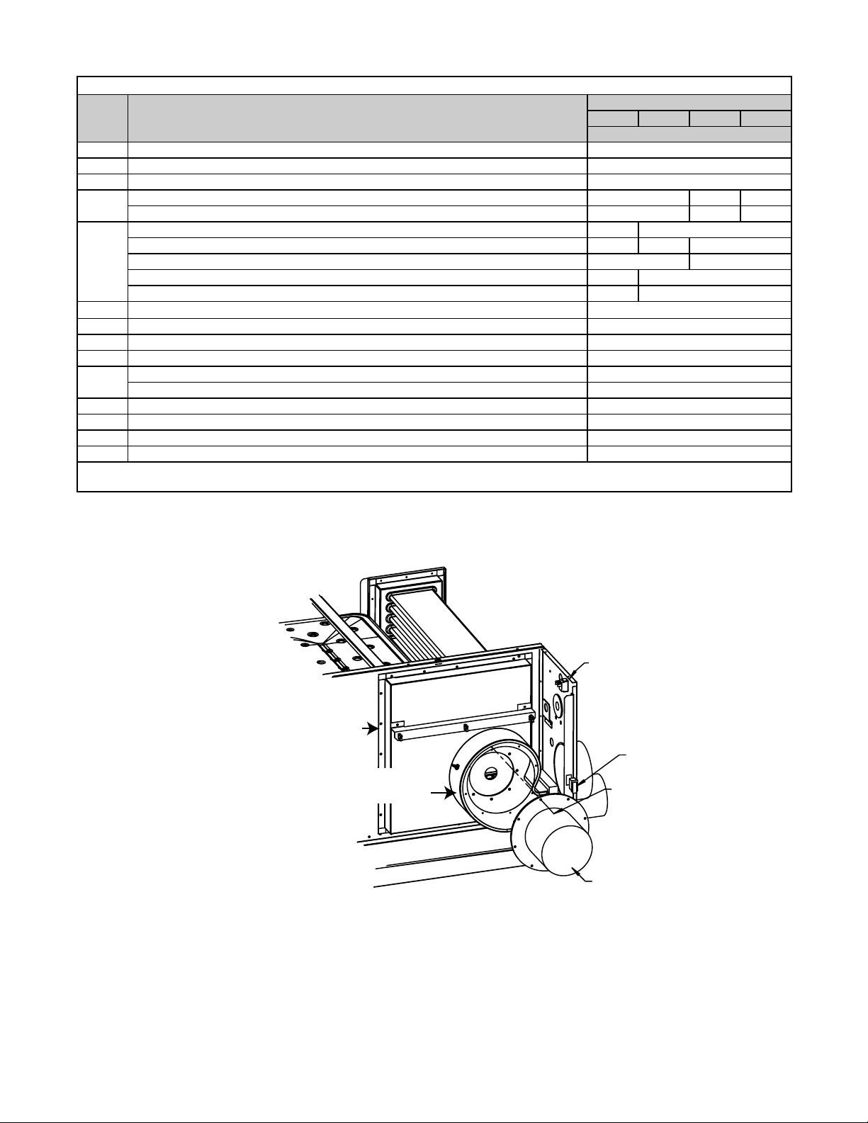
Table 2. Electrical Components
Unit Size
Code Component
1 Disconnect switch 101902
2 Door switch, Carling #TA22B-TLB-B 217262
3 Vent temperature limit switch, Thermodisc 36T26 73DD, opens at 145°F, manual reset 221158
High temperature limit switch, 180° 45602 — 45602
4
High temperature limit switch, 200°, yellow — 85449 —
Pressure switch, Honeywell, 0–6000 feet altitude, yellow 221251 —
Pressure switch, Honeywell, 0–6000 feet altitude, blue — 221228 —
5
Pressure switch, Honeywell, 0–6000 feet altitude, white — 1013436
Pressure Switch , Honeywell, 6001–10,000 feet altitude, green 235954 —
Pressure Switch , Honeywell, 6001–10,000 feet altitude, orange — 235953
6
Time delay relay, 24VAC, Airotronics*
7 Venter motor capacitor, 7.5 μF, 400VAC 195643
8 Fan motor capacitor, 7.5 μF, 400VAC 195643
9 Transformer, 120/24 volts 175265
DSI control module, integrated circuit board, serial number code 79 (refer to Serial Numbers) 195265
10
DSI control module, integrated circuit board, serial number code A1 (refer to Serial Numbers) 269867
11 Terminal board 196813
12 Gasket, terminal board 196327
13 Wiring harness, 9-pin 234021
14 Wiring harness, 5-pin 221868
*Used on units manufactured before DEC 2012. Time delay relay is not used with DSI control module, integrated circuit board (code 10, PN
269867).
130 180 260 310
PN
221388
FLUE WRAPPER AND VENTER COMPONENTS
20 - Flue Wrapper Side Gaskets
21 - Flue Wrapper Top/Btm Gaskets
22 - Flue Wrapper Assy
23 - Venter Inlet Gasket
24 - Venter Housing Assy
Figure 2. Flue Wrapper and Venter Components (Refer to Table 3)
Disconnect
Switch
Door Switch
(8) Screws,
PN 221178
25 - Venter Motor
and Wheel Assy
(see exploded view)
P-UEAS (11-18) PN269865R7
5
Page 6

FLUE WRAPPER AND VENTER COMPONENTS—CONTINUED
Exploded View of
Code 25: Venter Motor
and Wheel Assembly
25F/25G
25D
Stainless Nut,
(4) PN 221179
25E
25B
(size 130 only)
25C
25F
25A
“B”
25A
Dimension B
Size Inches mm
130 0.312 7.9
180 0.5 12.7
260 0.5 12.7
310 0.5 12.7
25H
25C/D
25J
Figure 3. Venter Motor and Wheel Assembly (Refer to Table 3)
Table 3. Flue Wrapper and Venter Components
Unit Size
Code Component
20 Flue wrapper side gaskets 221198 (2) 221199 (2)
Flue wrapper top gasket 221200
21
Flue wrapper bottom gasket 221200
22 Flue wrapper 220823 220824
23 Venter housing gasket 221164
24 Venter housing assembly (includes Code 24A and Code 3, vent temperature limit switch 221520
24A Static pressure tap 116043
25 Venter motor and wheel assembly 222648 221240
25A Venter motor, A.O. Smith F48Y67A13 221159
25B Flat washer 204323 (4)
25C Motor plate 221162
25D Motor plate gasket 221163
25E Slinger (smooth side must be flush against motor plate) 221861
25F Venter wheel 221172
25G Venter wheel housing 221173
25H Shaft protector gasket 221161
25J Shaft protector 221160
25K Setscrew 222077
*Quantity is one (1) unless otherwise indicated.
130 180 260 310
PN*
6
P-UEAS (11-18) PN269865R7
Page 7

31 - Fan
Blade
FAN AND MOTOR COMPONENTS
33 - Isolator
Setscrew
35 - Flat
Washer
36 - Nut
32 - Fan Guard
34 - Motor
Spacer
30 Fan
Motor
A
Dimension A
Size inches mm
130 2-3/8 60
180 2-3/8 60
260 251
310 1-3/8 35
Figure 4. Fan and Motor Components (Refer to Table 4)
Table 4. Fan and Motor Components
Unit Size
Code Component
Fan motor, 115V 271461 (replaces 196246) 196247
30
Fan motor,115V, AL14 (enclosed) 196824 196825
31
Fan blade**
32 Fan guard 170084 170086
33 Isolator 196348 (4)
34 Motor spacer — 204321
35 Flat washer 204323 (4)
36 Lock nut 271462 (4) 216942 (4)
*Quantity is one (1) unless otherwise indicated.
**Setscrew torque = 130 inch-pounds (±10 inch-pounds).
130 180 260 310
PN*
195680 195683 209121
Valve Code
(Refer to Serial Numbers)
Y2
Z7
Y3
Z8
6E
P-UEAS (11-18) PN269865R7
GAS CONVERSION KITS
Table 5. Natural Gas to Propane Conversion Kits
Unit Size
130 180 260 310
Kit PN
221442 221443 —
— 221444 221445
261647 261648 —
7
Page 8

44 - Burner
Baffle
38 - DSI
Electrode
42 - Burner
Shield Assy
39 - Flame
Sensor
43 - Burner
Support
41 - Burner
Body Assy
Screws,
PN 195638
40 - Burner
Inlet Plate
48 - Gas Valve
Manifold Assembly
45 - Orifice
46 - Orifice Adapter
47 - Pipe Nut
BURNER ASSEMBLY COMPONENTS
Figure 5. Burner Assembly Components (Refer to Table 6)
Code Component
38 DSI electrode 175272
39 Flame sensor 195292
40 Burner inlet plate 221165 221166 221167 221168
41 Burner body assembly 221476 195238 195241 195243
42 Burner shield assembly 195528 195529 195532 195534
43 Burner supports (4) 196598
44 Burner baffle (2) 197238 N/A
45
46 Orifice adapter 165701 194809
47 Pipe nut, 1/2-inch 165702
48 Natural gas valve 260603 196981
*Quantity is one (1) unless otherwise indicated.
Natural gas orifice (marking = #3) 211851 —
Natural gas orifice (marking = 6.2MM) — 221263 —
Natural gas orifice (marking = 7.6MM) — 196894 —
Natural gas orifice (marking = 0) — 221264
Propane orifice (marking = 3.3MM) 120415 —
Propane orifice (marking = 25) — 221265 —
Propane orifice (marking = 14) — 196902 —
Propane orifice (marking = 8) — 196903
Table 6. Burner Assembly Components
Unit Size
130 180 260 310
PN*
8
P-UEAS (11-18) PN269865R7
Page 9

MANUAL SHUTOFF VALVE
Header Gaskets
Figure 6. Manual Shuto Valve—Same as Option CE1 (Refer to Table 7)
Table 7. Manual Shutoff Valves
Option Package
15971 15972
Component
130 180 260 310
Shutoff valve, 1/2-inch 196910 —
Shutoff valve, 3/4-inch — 196911
Union, 1/2-inch 1224 —
Union, 3/4-inch — 1101
Unit Size
PN
HEAT EXCHANGER COMPONENTS
Code 51: Primary
Heat Exchanger
51A - (2) Side
51B - (2) Top/Btm
Header Gaskets
Figure 7. Heat Exchangers (Refer to Table 8)
Table 8. Heat Exchanger Components
Code Component
51 Primary heat exchanger assembly with drain assembly 221318 221319 221320 221321
51A Top/bottom header gaskets 221201 (2) 221202 (2)
51B Side header gaskets 221203 (2) 221204 (2)
51C Replacement HTEX drain kit 235368
52 Secondary heat exchanger assembly 221256 221257 221258 221259
52A Secondary heat exchanger header gasket 220804 220805
52B Collection box gasket 221187
*Quantity is one (1) unless otherwise indicated.
Code 52: Secondary
Heat Exchanger
52A - Header
Gasket
52B - Collection
Box Gasket
Unit Size
130 180 260 310
PN*
P-UEAS (11-18) PN269865R7
9
Page 10

CONDENSATE DRAIN KIT (PN 235368) FOR REPLACEMENT HEAT EXCHANGERS
PN 105949)
Drain Stub
Drain Pipe Assembly (PN 284192)
Assembly (PN 221245)
(two (2) required)
1/2-inch PVC Elbow (
Figure 8. Condensate Drain Kit (Refer to Table 9)
Table 9. Condensate Drain Kit (PN 235368) Components
Component PN Quantity
Elbow, 1/2-inch PVC 105949 1
Drain stub assembly 221245 2
Drain pipe assembly 284192 1
CONDENSATE DRAIN KIT (PN 235368) INSTALLATION
Install the condensate drain kit as follows:
1. Turn off gas and power.
2. Remove old primary heat exchanger.
3. Remove drain assembly from secondary heat exchanger.
4. Install new primary heat exchanger.
5. Thread one drain stub assembly into half coupling on new primary heat exchanger.
6. Thread other drain stub assembly into half coupling on seconday heat exchanger.
7. Install 1/2-inch PVC elbow and drain pipe assembly using PVC cleaner and solvent.
8. Turn on gas and power and check for operation according to installation manual.
VENT/COMBUSTION AIR COMPONENTS
Codes 55A and 56A:
Concentric Adapter
Box
Codes 55B and 56B:
Silicone Sealing Ring
Code 55C: Bird Screen
Code 56C: Bird Guard
Figure 9. Vent/Combustion Air Components (Refer to Table 10)
Model
UEAS
Codes 55G
and 56G:
4-inch PVC Cap
Code 56E: Combustion
Air Inlet
Code 55D: Ring Guard
Code 56F: Rain Collar
10
P-UEAS (11-18) PN269865R7
Page 11

Table 10. Vent/Combustion Air Terminal Kits
Code Component PN Quantity
Code 55: Horizontal Kit (PN 221247, Same as Option CC6)
55A Concentric adapter box 221069 1
55B Sealing ring, silicone — 1
55C Bird screen, for exhaust outlet 221089 1
55D Ring guard, for air inlet 124940 4
55E Screw, #10-16 × 1/2-inch long, for attaching inlet air guard 37661 4
55F Spacer, for inlet air guard 221186 4
55G Condensate drain connection vent cap, 4-inch PVC 221091 1
Code 56: Vertical Kit (PN 221248, Same as Option CC2)
55A Concentric adapter box 221069 1
55B Sealing ring, silicone — 1
55C Bird guard 221215 1
55D Screw, #10 × 1/2-inch long, self-drilling, for bird guard 37661 2
55E Combustion air inlet 221250 1
55F Rain collar 221185 1
55G Condensate drain connection vent cap, 4-inch PVC 221091 1
NOTE: The following vent/combustion air components are for separated combustion: concentric
adapter box (codes 55A and 56A), silicone sealing ring (codes 55B and 56B), 4-inch PVC cap (codes 55G
and 56G).
LOUVER ASSEMBLY COMPONENTS
Figure 10. Vertical Louvers—Same as Option CD1 (See Table 11)
Table 11. Louver Assembly Components
Option Package
201199 201201
Component
130 180 260 310
Louver frame top and bottom 197189 (2) 197190 (2)
Louver frame side 197186 (2) 197188 (2)
Screw, #8-18 × 3/8-inch long, AB point, slotted indented serrated hex washer head 195638 (20)
Louver 196572 (8) 195315 (8)
Compression spring 195046 (8)
P-UEAS (11-18) PN269865R7
Unit Size
PN (Quantity)
11
Page 12

NOZZLE COMPONENTS
Figure 11. Downturn Nozzles—Same as Option CD2, CD3, or CD4 (Refer to Table 12)
Table 12. Nozzle Components
Unit Size
Component
Option CD2 Package PN 201202 201204
Nozzle section right side 197173 (1) 197175 (1)
Nozzle section left side 197176 (1) 197178 (1)
Nozzle section top 197170 (1) 197172 (1)
Nozzle bracket 201708 (2) 201709 (2)
Nozzle section bottom 196997 (1) 197179 (1)
Screw, #8-18 × 3/8-inch long, AB point,
slotted indented serrated hex washer head
Option CD3 Package PN 201205 201207
Nozzle section right side 197173 (2) 197175 (2)
Nozzle section left side 197176 (2) 197178 (2)
Nozzle section top 197170 (2) 197172 (2)
Nozzle bracket 201708 (2) 201709 (2)
Nozzle section bottom 196997 (2) 197179 (2)
Screw, #8-18 × 3/8-inch long, AB point,
slotted indented serrated hex washer head
Option CD4 Package PN 201208 201210
Nozzle section right side 197173 (1) 197175 (1)
Nozzle section left side 197176 (1) 197178 (1)
Nozzle section top 197170 (1) 197172 (1)
Nozzle bracket 201708 (2) 201709 (2)
Nozzle section bottom 196997 (1) 197179 (1)
Vertical louver 196572 (8) 195315 (8)
Compression spring 195046 (8)
Top louver support 197189 (1) 197190 (1)
Bottom louver support 197189 (1) 197190 (1)
Louver frame side 197186 (2) 197188 (2)
Screw, #8-18 × 3/8-inch long, AB point,
slotted indented serrated hex washer head
130 180 260 310
PN (Quantity)
195638 (16)
195638 (30)
195638 (28)
12
P-UEAS (11-18) PN269865R7
Page 13

HANGER KIT COMPONENTS
Figure 12. Hanger Kit—Same as Option CK10 (Refer to Table 13)
Table 13. Hanger Kit Components
Unit Size
Component
Option CK10 Package PN 98511
Swivel connector assembly 17627 (4)
Lockwasher, 3/8-inch 5197 (8)
Nut, hex, 3/8-inch 1438 (4)
NOTE: Hanger kit provides four-point suspension.
130 180 260 310
PN (Quantity)
THERMOSTAT COMPONENTS
Thermostat Thermostat
Cover
Figure 13. Thermostat and Cover—Same as Options CL1 and CM1 (Refer to Table 14)
Table 14. Thermostat Components
Unit Size
Component
Thermostat, single-stage, 24V, with fan switch (same as option CL1) 255350
Cover, thermostat, locking, 6 × 5 × 2-1/2 (inside), clear plastic (same as option CM1) 257464
130 180 260 310
PN
P-UEAS (11-18) PN269865R7
13
Page 14

CABINET COMPONENTS
Control Side of
Sizes 130 and 180
Front
59 - Door Panel
Control Side of Sizes 260 and 310
59 - Door Panel
60 - Access Panel
65 - Front
Panel
66 - Left
Panel
70 - Top
68 - Louver
69 Spring
Fan Side (Rear)
61 - Vent Panel
63 - Vent Block Cover
64 Fan
Panel
67 - Bottom Pan
70 - Top
62 - Vent Block Assembly
(block, pipe, and gasket)
Figure 14. Cabinet Components (Refer to Table 15)
14
P-UEAS (11-18) PN269865R7
Page 15

Table 15. Cabinet Components
Unit Size
Code Component
59 Door assembly 220833 220834
60 Access panel, above door — 220822
61 Vent panel assembly 220825 220826
62 Vent block assembly 221518
62A Vent block gasket, part of code 62 221516
63 Vent block cover assembly 221519
64 Fan panel 220759 220760
65 Front panel 201692 201694
66 Left panel 220753 220754
67 Bottom pan 220827 220828
68 Louver 195578 (5) 195578 (10)
69 Louver spring 195046 (5) 195046 (10)
70 Top panel 220755 220756
71 T-CORE3 logo 221183
73 Touch-up paint, cabinet, white, 11-oz spray can 201805
74 Paint, horizontal louver, maroon, 12-oz spray can 207432
*Quantity is one (1) unless otherwise indicated.
130 180 260 310
PN*
P-UEAS (11-18) PN269865R7
15
Page 16

Specifications and illustrations subject to change without notice or incurring obligations.
©2018 Nortek Global HVAC LLC, O’Fallon, MO.
All rights reserved.
 Loading...