

Page 1
10.0 Maintenance
and Service
(cont’d)
10.2 Maintenance
Procedures
(cont’d)
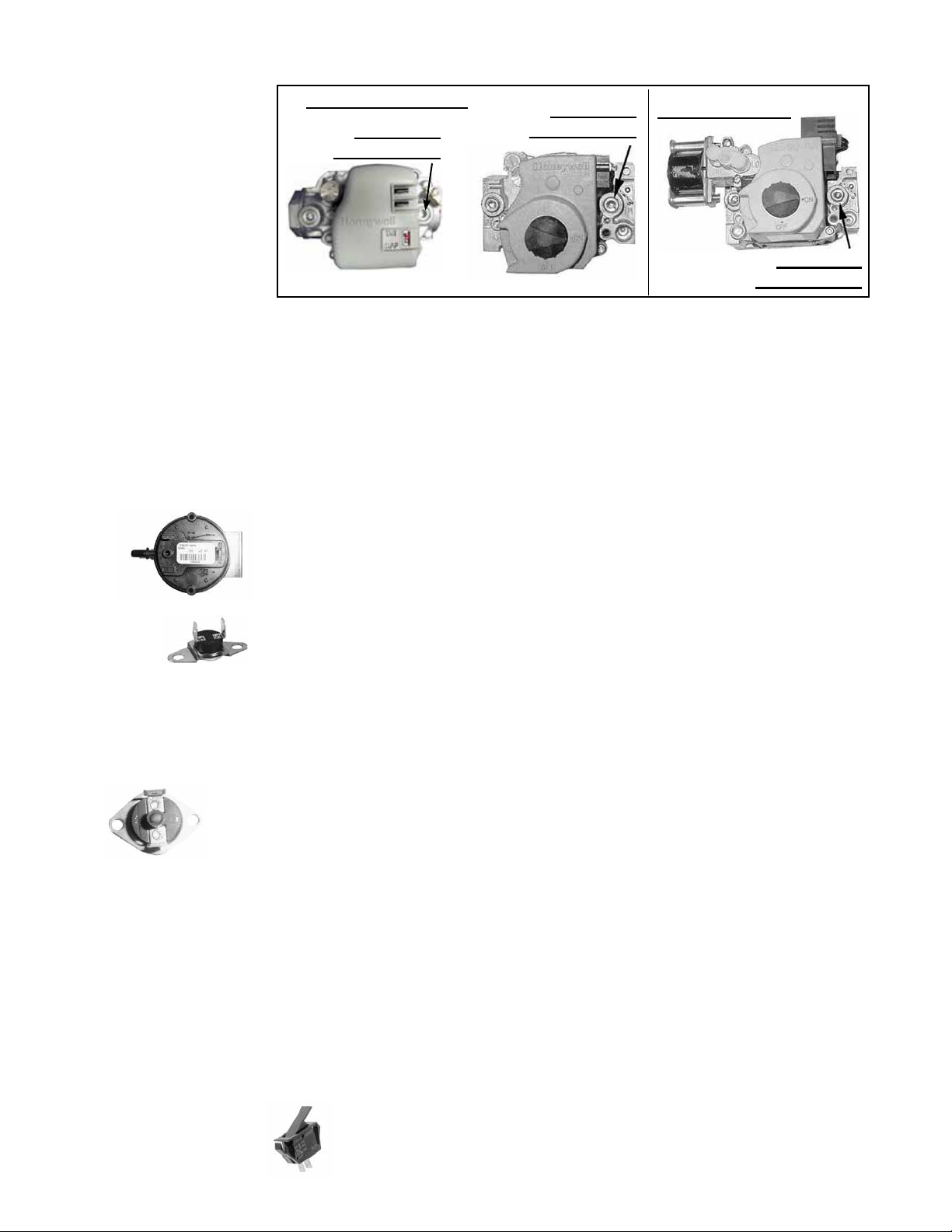
FIGURE 24 - Pressure
Tap for Checking Gas
Flow Shuto
10.2.7 Operating Gas Valve (cont’d)
Single-Stage Valves
1/8ʺ Outlet
Pressure Tap
1/8ʺ Outlet
Pressure Tap
Two-Stage Valve
1/8ʺ Outlet
Pressure Tap
NOTE: Operational
pressure settings and
instructions for checking
pressure settings are in
Paragraph 6.1.
10.2.8 Combustion Air
Pressure Switch
10.2.9 Limit
Control
10.2.10 Flame Rollout
Switch—Sizes 30–125
only
2) With the manual valve turned o to prevent ow to the gas valve, connect a
manometer to the 1/8ʺ outlet pressure tap in the valve. NOTE: A manometer (uidlled gauge) is recommended.
3) Turn the manual valve to the ON position and the heater OFF. Use your nger to
fully block the main burner orice for several seconds. Observe the manometer
with the orice blocked, and if any pressure is indicated, the gas valve is leak-
ing. A leaking gas valve must be replaced before the heater is put back in
operation.
See FIGURE 18, page 30, for location. (NOTE: Depending on date of manufacture and
size, pressure switch may not be in the location indicated. Check the control bracket
on the bottom of the compartment or further down on the compartment wall.) If it is
determined that the pressure switch needs replacing, use only the factory-authorized
replacement part that is designed for the model and size of heater being serviced.
NOTE: A unit operating above 6000 ft (1830M) elevation requires a high altitude pressure switch (see Paragraph 3.2).
If it is determined that the limit control needs replacing, use only a factory-authorized
replacement part that is designed for the size of heater.
For approximate limit location, see FIGURE 18, page 30.
The cause of a ame rollout switch activating must be determined. Activation of the
manually reset ame rollout switch could be caused by one or more of the following:
• Restricted or plugged heat
exchanger
• Too much building exhaust
• Manifold gas pressure too
high
• Restricted combustion air inlet or exhaust outlet
in combination with a defective pressure switch
• Electrical power interruption during operation
• Unit being operated with a line voltage
disconnect (a 24-volt thermostat is required)
If a ame rollout switch trips, inspect the burner/control compartment for signs of
excessive heat and burned wiring.
For location, see
FIGURE 18, page 30.
If the compartment appears normal, reset by depressing the red button on the
switch. 15 to 20 minutes are required for the switch to cool suciently for resetting. A distinct click will be felt when the switch resets. Operate the furnace. If the
ame rollout switch trips again, determine and correct the cause before resetting
the switch.
If there is damage to the control compartment, repairs must be made before
resetting the switch.
If it is determined that the ame rollout switch needs replacing, use only the factory-
authorized replacement part that is designed for that size of heater.
The disconnect switch is located in the sealed electrical box inside the control com-
partment with the toggle on the rear of the heater.
10.2.11 Door
Switch—Separated
Combustion Model
only
Page 34, D300519A (04-18) I-UDA&APD Series
If it is determined that the door switch needs replacing, use only a factory-
authorized replacement part that is designed for the heater.
For approximate switch location, see FIGURE 18, page 30.
Page 2
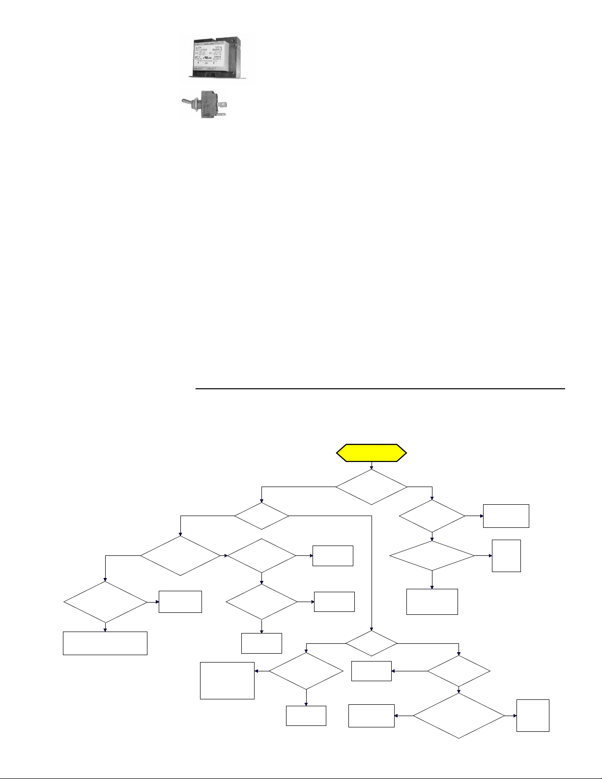
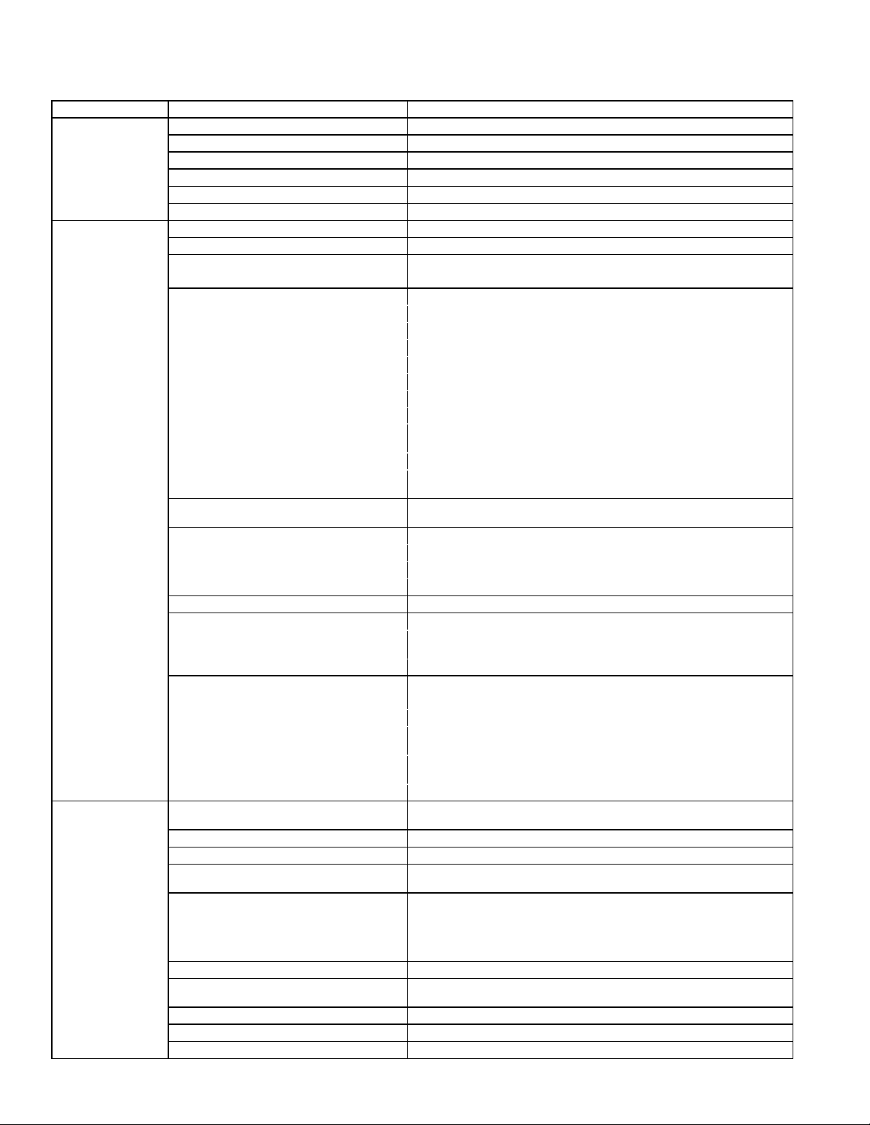
10.2.12 Transformer
Trial for Ignition
Call for Heat
Is there a
spark across gap at
ignitor?
Does gas
ignite?
Is there minimum
flame current at the
flame sensor?
Is there
minimum flame current
at the control
module?
Replace control
module.
Check connections to flame
sensor and/or moisture in the
burner assembly.
Is the flame
sensor corroded?
Clean flame
sensor.
Is the sensor
located in flame
correctly?
Replace flame
sesnsor.
Reposition
flame sensor.
Is gas
flowing?
Is the ignitor
position correct in the
gas flow?
Check gas pressure
and supply voltage.
If either are low,
correct and repeat
startup.
Reposition
spark ignitor.
Is there
24VAC at the gas
valve?
Is there 24VAC
from gas valve output on
control module to
chassis?
Check wiring and
connections to
gas valve.
Replace
ignition
control
module.
Replace gas
valve.
Is there
spark voltage at
control?
Check high
voltage wire
continuity.
Is there 24V P1-2
to power control?
Replace
control
module.
Check wiring
and/or 24VAC
transformer output.
YES NO
YES NO
YES NO
YES
NO
YES
NO
YES
NO
YES NO
YES
NO
NO
YES
YES NO
YES
NO
YES
NO
10.2.13 Disconnect
Switch—Separated
Combustion model
only
10.2.14 Vent or Vent/
Combustion Air
System
10.3 Troubleshooting
Check the Lights on
the DSI Integrated
Control Module
(Circuit Board)
IMPORTANT: When using
a multimeter to troubleshoot
the 24 volt circuit, place the
meter’s test leads into the 5
or 9 pin connectors located
on the ignition control. Do
not remove connectors or
terminals from the electrical components. Doing so
can result in misinterpreted
readings due to the ignition
control board’s fault mode
monitoring circuits.
See FIGURE 18, page 30, for location. Use a voltmeter to verify that
there are 24 volts output from the transformer. If the transformer is not
functioning, it must be replaced. Use a replacement transformer identi-
cal to the factory-installed model.
If it is determined that the disconnect switch needs replacing, use only the
factory-authorized replacement part that is designed for the heater. Always
replace electrical box cover.
Check the complete system at least once a year. Inspection should include all joints,
seams, concentric adapter box (Separated Combustion), inlet air guard or inlet air cap
(Separated Combustion), and the vent terminal cap. Clean openings. Replace any
defective parts.
The integrated circuit board monitors the operation of the heater and includes two
LED signal lights that indicate normal operation and various abnormal conditions. If
the heater fails to operate properly, check this signal to determine the cause and/or
to eliminate certain causes. LED is visible through viewport on Separated Combustion models. Remove access panel on Standard Power Vent models. See operating
sequence in Paragraph 9.
Do not attempt to repair the DSI integrated control module (circuit board); the only eld
replaceable component is the fuse.
Control Status—Green LED Codes
Steady ON Normal Operation, No call for heat
Fast Flash . Normal Operation, Call for heat
1 Flash ...... System Lockout, Failed to detect or sustain ame
2 Flashes .. Pressure Switch Did Not Close within 30 Seconds of Venter Motor
3 Flashes .. High Limit or Flame Rollout Switch Open
4 Flashes ....Pressure Switch is Closed Before Venter Motor is Energized
Steady OFF Blown fuse, No Power, or Defective Board
Flame Status—Yellow LED Codes
Steady ON ..Flame is sensed
Slow Flash ..Weak ame (current below 1.0 microamps ± 50%)
Fast Flash ...Undesired Flame (valve open and no call for heat)
DSI Integrated Control Module (Circuit
Board) Trial Troubleshooting Flowchart
D300519A (04-18) I-UDA&APD Series, Page 35
Page 3
10.3 Troubleshooting (cont’d)
General Troubleshooting
PROBLEM PROBABLE CAUSE REMEDY
Venter motor will not
start
Burner will not light 1. Manual valve not open. 1. Open manual valve.
Burner cycle on and o1. Gas pressure too high or too low. 1. Supply pressure should be 5–14" w.c. for natural gas or 11–14" w.c. for pro
1. No power to unit. 1. Turn on power, check supply fuses or circuit breaker.
2. No 24 volt power to integrated circuit board. 2. Turn up thermostat; check control transformer output.
3. Integrated circuit board fuse blown. 3. Correct cause. Replace fuse (type ATC or ATO, 32VDC, 3A).
4. No power to venter motor. 4. Tighten connections at circuit board and/or motor terminals.
5. Integrated circuit board defective. 5. Replace integrated circuit board.
6. Defective venter motor. 6. Replace venter motor (see Paragraph 29).
2. Air in the gas line. 2. Bleed gas line (initial startup only).
3. Gas pressure too high or too low. 3. Supply pressure should be 5–14" w.c. for natural gas or 11–14" w.c. for
4. No Spark:
a) Loose wire connections a) Be certain all wire connections are solid.
b) Transformer failure.
c) Incorrect spark gap. c) Maintain spark gap at 1/8".
d) Spark cable shorted to ground. d) Replace worn or grounded spark cable.
e) Spark electrode shorted to ground. e) Replace if ceramic spark electrode is cracked or grounded.
f) Burner not grounded. f) Make certain integrated circuit board is grounded (Terminal P1-9).
g) Circuit board not grounded. g) Make certain integrated circuit board is grounded to furnace chassis.
h) Unit not properly grounded. h) Make certain unit is properly eld grounded to earth ground and properly
i) Integrated circuit board fuse blown. i) Correct cause. Replace fuse (type ATC or ATO, 32VDC, 3A).
j) Faulty integrated circuit board. j) If 24 volt is available to the integrated circuit board and all other causes have
5. Lockout device interrupting control circuit by
above causes.
6. Combustion air proving switch not closing. 6.
7. Faulty combustion air proving switch. 7. Replace combustion air proving switch.
8. Main valve not operating. 8.
a) Defective valve. a) If 24 volt is measured at the valve connections and valve remains closed,
b) Loose wire connections b) Check and tighten all wiring connections.
9. Integrated circuit board does not power main
valve.
a) Loose wire connections. a) Check and tighten all wiring connections.
b) Flame sensor grounded. b) Be certain ame sensor lead is not grounded or insulation or ceramic is not
c) Incorrect gas pressure. c) Supply pressure should be 5–14" w.c. for natural gas or 11–14" w.c. for pro
d) Cracked ceramic at sensor. d) Replace sensor.
2. Burner not grounded 2. Make certain integrated circuit board is grounded (Terminal P1-9).
3. Circuit board not grounded. 3. Make certain integrated circuit board is grounded to furnace chassis.
4. Faulty integrated circuit board 4. If 24 volt is available to the integrated circuit board and all other causes have
5. Combustion air proving switch not closing. 5.
6. Faulty combustion air proving switch. 6. Replace combustion air proving switch.
7. Flame sensor grounded. 7. Be certain ame sensor lead is not grounded or insulation or ceramic is not
8. Cracked ceramic at sensor. 8. Replace sensor.
9. Incorrect polarity. 9. Reverse line volt leads to integrated circuit board.
10. Pin terminal loose on 9 pin plug. 10. Replace wire harness.
:
propane.
4.
b) Be sure 24 volts is available.
phased (L1 to hot lead L2 to neutral).
been eliminated, replace board.
5. Reset lockout by interrupting control at the thermostat or main power.
a) Make sure unit is properly vented.
b) Remove obstructions from vent.
c) Replace faulty tubing to pressure switch.
replace valve.
9.
cracked. Replace as required.
pane.
pane.
been eliminated, replace board.
a) Make sure unit is properly vented.
b) Remove obstructions from vent.
c) Replace faulty tubing to pressure switch.
cracked. Replace as required.
-
-
Page 36, D300519A (04-18) I-UDA&APD Series
Page 4

No heat (Heater Operating)
Fan or venter motor
will not run
Fan or venter motor
turns on and o while
burner is operating
Fan or venter motor
cuts out on overload
1. Incorrect valve outlet pressure or orice. 1. Check valve outlet pressure (see Rating plate for manifold pressure).
2. Cycling on limit control. 2. Check air throughput.
3. Improper thermostat location or adjustment. 3. See thermostat manufacturer's instructions.
1. Circuit open. 1. Check wiring and connections.
2. Defective integrated circuit board. 2. Replace board.
3. Defective motor or starter. 3. Replace motor or starter.
1. Motor overload device cycling on and o. 1. Check motor load against motor rating plate. Replace motor if needed.
1. Low or high voltage supply. 1. Correct electric supply.
2. Defective motor. 2. Replace motor.
3. Poor airow. 3. Clean motor, fan, fan guard, lter, and coils.
D300519A (04-18) I-UDA&APD Series, Page 37
Page 5

APPENDIX
TECHNICAL DATA—Sizes 30–125 (Data applies to all Models unless noted otherwise)
Size 30 45 60 75 100 125
Input Heating Capacity
Thermal Eciency (%) 82 83 83 83 83 83
Output Heating Capacity
Gas Connection (inches)
Vent Connection (inches diameter)
A
B
C
Combustion Air Inlet (inches diameter)—Separated Combustion only
Control Amps (24 volt) 1.0 1.0 1.0 1.0 1.0 1.0
Full Load Amps (115 volt) 1.9 2.4 2.4 3.3 3.9 5.1
Maximum Over Current
Protection
D,E
Normal Power Consumption (watts) 109 155 155 217 276 354
Discharge Air Temperature Rise (°F) 50 55 60 60 60 60
Air Volume
Discharge Air Opening Area
Output Velocity
Fan Motor HP
E
Fan Motor RPM 1550 1550 1550 1550 1050 1050
Fan Diameter (inches) 10 10 12 12 16 16
Sound Level dba @ 15 ft 40 40 40 49 54 55
TECHNICAL DATA—Sizes 150–400 (Data applies to all Models unless noted otherwise)
Size 150 175 200 225 250 300 350 400
Input Heating Capacity
Thermal Eciency (%) 83 83 83 83 83 83 83 83
Output Heating Capacity
Gas Connection (inches)
Vent Connection
Combustion Air Inlet
A
B
C
(inches diameter) 5 5 5 5 5 6 6 6
C
(inches diameter)—Separated Combustion only 6 6 6 6 6 6 6 6
Control Amps (24 volt) 1.0 1.0 1.0 1.0 1.0 1.0 1.0 1.0
Full Load Amps (115 volt) 3.8 3.8 7.5 7.5 7.5 10.7 10.7 10.7
Maximum Over Current
Protection
D,E
Normal Power Consumption (watts) 392 392 491 747 747 1086 1086 1086
Discharge Air Temperature Rise (°F) 60 60 60 60 60 60 60 60
Air Volume
Discharge Air Opening Area
Output Velocity
Fan Motor HP
E
Fan Motor RPM 1050 1050 1050 1050 1050 1050 1050 1050
Fan Diameter (inches) 18 18 18 20 20 24 24 24
Sound Level dba @ 15 ft 51 52 53 56 56 59 61 62
A
CSA ratings for altitudes to 2000 ft.
B
Size shown is for gas connection to a single-stage gas valve, not supply line size.
C
Smaller and/or larger vent and combustion air pipe diameters may be permissible. For Separated Combustion models refer to the Venting
Installation Manual for Separated Combustion Units. For Standard Power Vent models refer to the Venting Installation Manual for Power Vented
units. For a Standard Power Vent model with Option AV6, refer to the Venting Installation Manual for Common Venting.
D
MOCP = 2.25 × (largest motor FLA) + smallest motor FLA. Answer is rounded to the next lower standard circuit breaker size.
E
Except where indicated, information in this table is based on a heater equipped with a standard 115 volt open fan motor.
BTUH 30,000 45,000 60,000 75,000 105,000 120,000
kw 8.8 13.2 17.6 22.0 30.8 35.2
BTUH 24,600 37,350 49,800 62,250 87,150 99,600
kw 7.2 11.0 14.6 18.3 25.6 29.2
Natural 1/2 1/2 1/2 1/2 1/2 1/2
Propane 1/2 1/2 1/2 1/2 1/2 1/2
4 4 4 4 4 4
C
4 4 4 4 4 4
Standard 115V 15 15 15 15 15 15
Optional 208V or 230V 15 15 15 15 15 15
CFM 456 629 769 961 1345 1537
3
/minute 12.9 17.8 21.8 27.5 36.7 45.9
M
2
ft
2
M
1.0 1.0 1.2 1.2 2.0 2.0
0.1 0.1 0.1 0.1 0.2 0.2
FPM 475 656 616 770 668 763
M/minute 145 200 188 238 196 245
Standard Open 0.0 0.0 0.0 0.1 1/30 1/20
Optional Enclosed N/A N/A N/A N/A 1/4 1/4
BTUH 150,000 175,000 200,000 225,000 250,000 300,000 350,000 400,000
kw 43.9 51.2 58.6 65.9 73.2 87.8 102.5 117.1
BTUH 124,500 145,250 166,000 186,750 207,500 249,000 290,500 332,000
kw 36.4 42.5 48.6 54.7 60.8 72.9 85.1 97.2
Natural 1/2 1/2 1/2 3/4 3/4 3/4 3/4 3/4
Propane 1/2 1/2 1/2 3/4 3/4 3/4 3/4 3/4
Standard 115V 15 15 15 15 15 20 20 20
Optional 208V or 230V 15 15 15 15 15 15 15 15
CFM 1921 2242 2562 2882 3202 3843 4483 5123
3
/minute 54.4 63.5 72.5 81.6 90.7 108.8 126.9 145.1
M
2
ft
2
M
2.6 2.6 2.6 3.5 3.5 4.8 4.8 4.8
0.2 0.2 0.2 0.3 0.3 0.5 0.5 0.5
FPM 752 877 1003 820 9 11 802 936 1069
M/minute 229 267 306 250 278 244 285 326
Standard Open 1/6 1/6 1/4 1/4 1/4 1/2 1/2 1/2
Optional Enclosed 1/4 1/4 1/4 1/4 1/4 1/2 1/2 1/2
Page 38, D300519A (04-18) I-UDA&APD Series
Page 6

INDEX
A
Abnormal Heat Cycle Functions 24
Aircraft Hangars 4
Control Amps 38
Full Load Amps 38
APPENDIX 38
B
Clean the Burner 31
Burner Maintenance 30
Burner Orice 31
Burner Removal 30
C
California Warning Label 4
Ceiling Suspension Kit 11
Certication 3
Check installation after startup 27
Check the installation prior to
startup 26
Check the Lights 35
Chlorine 6
Clearances 7
LED Codes 23, 35
Combustion Air 16
Combustion Air Inlet 38
Combustion Air Pressure Switch 34
Combustion Air Proving (Pressure)
Switch 20
Commissioning 26
Conned Space 16
Contact 40
Control Wiring 17
Conversion Kits 13
D
DDC Controls 22
Dimensions 8
Disconnect Switch 35
Door Switch 34
Door Switch—Separated Combustion
Model only 21
Downturn Nozzle Kits 7
DSI Integrated Control Module 23, 31
E
Thermal Eciency 38
Electrical Supply 16
F
Continuous Fan Operation 25
Fan/Blower O Delay 24
Fan/Blower On Delay 24
Fan Blades 32
Fan Motor 21
Fault Modes 25
Field-Installed Parts 6
Flame Rollout Switch 34
Flame Sensor 32
G
Garages 4
Gas Connection 38
Gas Connection Size 12
Gas Supply 11
Gas Supply Line 12
Gas Valve 21, 33
Gas Valve ON/OFF Control Knob 27
H
Hanger Kits 11
Hanging the Heater 10
HAZARD INTENSITY LEVELS 2
Hazard Labels and Notices 2
Heat Exchanger Maintenance 30
High Altitude Capacity 15
High Altitude Derate 14
High Altitude Kit 6, 7
I
Ignition System 23, 31
Ignition Trial Period 23
Ignitor 32
Input Heating Capacity 38
Installation Codes 4
L
Leak-test 12
Lifting 10
LED lights 23
Limit Control 20, 34
Limit Switch 24
Literature Bag 28
Location 5
Unit Heater Location 4
Location of Controls 29
Lockout 25
Optional vertical louvers 6
M
Maintenance Procedures 30
Maintenance Schedule 29
Massachusetts Requirement 4
Fan Motor 32
Venter Motor 33
Motor HP 38
Multiple Heater Control 22
N
Normal Heat Cycle 23
O
Operating Sequence 27
Option CC1 6
Option CC2 or CC6 3, 6
Option CD 2, 3, or 4 7
Option CK8, CK10, and CK22 11
Option CL31 22
Option CL32 22
Option CM3 21
Option DJ20 or DJ21 6
Options D10 and D14 22
Orice Pressure 13
Output Heating Capacity 38
P
Plug the unused suspension points 10
Post Purge 24
Power Interruption 25
Preparing for Installation 6
Prepurge 23
Pressure Switch 24
Pressure Switch Settings 20
PRESSURE TESTING SUPPLY
PIPING 11
S
Mounting the Sensor 22
Sound Level 38
Spark Gap 32
Startup 26
Stepdown transformer 6
Supply Wiring 17
Suspending 10
Suspending the Heater with Rods 11
Suspend the Heater from 1ʺ Pipe 11
Swivel Connectors 11
T
TECHNICAL DATA 38
Thermostat 21
Unit Mounted Thermostat 21
Throw 4
Transformer 35
Troubleshooting 35, 36
Troubleshooting Flowchart 35
TURN OFF GAS TO THE APPLI-
ANCE 27
U
Uncrating and Inspecting 6
V
Valve Outlet Pressure 13
Vent 35
Vent/Combustion Air 35
Vent/Combustion Air Kit 3
Vent/combustion air kit 6
Vent cap 6
Vent Connection 38
Venter Wheel 33
Venting Manual 3, 5
Vent System Testing Procedure—Stand
Power Vent Model 27
W
Warranty 4
Weights 10
WHAT TO DO IF YOU SMELL GAS 26
Wiring Connections 17
Wiring Diagram for all Single Stage
Models 18
Wiring Diagram for all Two Stage Gas
Valve 19
Wiring Diagrams 18
D300519A (04-18) I-UDA&APD Series, Page 39
Page 7

INSTALLATION RECORD—to be completed by the installer:
Installer:
Name ________________________________________________________
Company ________________________________________________________
Address ________________________________________________________
________________________________________________________
________________________________________________________
Phone _________________________________
Distributor (company from which the unit was purchased):
Company ________________________________________________________
Contact ________________________________________________________
Address ________________________________________________________
________________________________________________________
________________________________________________________
Phone _________________________________
Model ________________ Serial No.______________________________Date of Installation ____________
SPECIFIC INSTALLATION NOTES: (i.e. Location, Amps, Gas Pressure, Temperature, Voltage, Adjustments,
Warranty, etc.)
________________________________________________________________________________________
________________________________________________________________________________________
________________________________________________________________________________________
________________________________________________________________________________________
________________________________________________________________________________________
BUILDING OWNER OR MAINTENANCE PERSONNEL:
For service or repair
• Contact the installer listed above.
• If you need additional assistance, contact the Distributor listed above.
• For more information, contact your Local Representative.
Page 40, D300519A (04-18) I-UDA&APD Series
Specications & illustrations subject to change without notice of incurring obligations.
©Nortek Global HVAC, LLC 2018. All rights reserved.
All marks are the property of their respective organizations.
O’Fallon, MO I Printed in U.S.A. (04-18)
Document No. D300519A (04-18) I-UDA&APD Series
 Loading...