

Page 1

NOTICE:
The information contained on the following page(s) was produced
prior to May 1, 2014. On that date Reznor became part of
Nortek, Inc.
References to any other company afliations are no longer valid.
©2014 Reznor, LLC. All Rights Reserved.
Trademark notice: Reznor is registered in at least the United States.
0514 PDF Form Cover1
Page 2
Sizes 45, 60 and 75
are certified to
CSA Requirement
10-96 for
RESIDENTIAL
INSTALLATION
®
APPLIES TO: Installation/Operation/Service
Separated-Combustion,
Power-V ented
INST ALLA TION FORM RZ-I-SFT
Obsoletes Form RZ 432 (V ersion C)
Model SFT
Gas-Fired,
Unit Heaters
Models SFT 45, 60 and 75 are certified for both residential and commercial/industrial installations.
Models SFT 100-300 are certified for commercial/industrial installations only.
Table of Contents
Installation and Operation......................................................... Paragraphs 1-17....................Pages 1-15
Check Installation and Start-Up ....................................................Paragraph 18 ..................Pages 16-17
Maintenance/Troubleshooting/Service ................................... Paragraphs 19-31 ..................Pages 18-24
Index By Page No.
Burner Orifices ........................................ 19
Burner Removal....................................... 18
Burners .................................................... 14
Check Installation and Start-Up .............. 16
Clearances.................................................. 3
Combustion Air ......................................... 6
Combustion Air Proving Switch........ 14, 21
Concentric Adapter Box ............................ 6
Dimensions ................................................ 5
Downturn Nozzles (Option Kit) ................ 2
Electrical Supply and Connections.......... 13
Fan ........................................................... 20
Fan Motor ................................................ 13
Flame Rollout Switch .............................. 21
Gas Piping and Pressures ........................ 12
Gas V alve........................................... 14, 21
REFERENCES: Replacement Parts, Form RZ-NA-P-FT/SFT
Index By Page No.
General .................................................... 1
Hazard Intensity Levels ........................... 2
Heat Exchanger ..................................... 19
High Altitude Combustion Air
Pressure Switch ...................... 3, 13
High Altitude Operation ........................ 3
Ignition Control Module ....................... 14
Ignition Control Module LED
Codes ..................................... 14, 21
Ignition System................................ 14, 19
Installation Codes .................................... 2
Limit Control ......................................... 21
Location (Heater)..................................... 3
Louvers, Vertical (Option Kit)................. 2
Maintenance .......................................... 18
Manifold Pressure.................................. 13
Gas Conversion, Form RZ-NA-I-FT/SFT -GC
FOR YOUR SAFETY
What to do if you smell gas:
• Do not try to light any appliance.
• Do not touch any electrical switch; do
not use any phone in your building.
• Immediately call your gas supplier from
a neighbor's phone. Follow the gas
supplier's instructions.
• If you cannot reach your gas supplier,
call your fire department.
Do not store or use gasoline or other flammable
vapors and liquids in the vicinity of this or any
other appliance.
Index By Page No.
Rating Plate .......................................... 23
Serial No. .............................................. 23
Service .................................................. 18
Start-Up ................................................ 16
Suspending ............................................. 3
Thermostat ............................................ 13
Troubleshooting.................................... 21
Uncrating and Preparation...................... 2
V ent/Combustion Air System ........... 6, 21
Horizontal Vent Terminal/
Combustion Air Inlet (Opt CC6) ...... 7-9
Vertical Vent T erminal/Combustion
Air Inlet (Opt CC2) .................... 10-11
Venter Motor ........................................ 20
Warranty ................................................. 2
Wiring Diagram .................................... 15
WARNING: Gas-fired appliances are not
designed for use in hazardous atmospheres
containing flammable vapors or combustible
dust. See Hazard Levels, page 2.
GENERAL
Installation should be done by a qualified agency in accordance with
the instructions in this manual and in compliance with all codes and
requirements of authorities having jurisdiction. The instructions in this
manual apply to the separated-combustion unit heater model shown
below.
Model Description
SFT Separated-Combustion,
Fan-Type, Suspended
Unit Heater
WARNING: Improper installation, adjustment,
alteration, service, or maintenance can cause
property damage, injury, or death. Refer to this
manual. For assistance or additional information,
consult a qualified installer, service agency, or
the gas supplier.
All sizes of Model SFT heaters are design-certified by the Canadian
Standards Association (CSA) to ANSI Z83.8a and CGA 2.6a for industrial/commercial installations in the United States and Canada. Models SFT 45, 60 and 75 are approved by the Canadian Standards Association to CSA 10-96 for residential installations in both the United
States and Canada. All heaters are available for use with either natural
or propane gas. The type of gas, the firing rate, and the electrical characteristics are on the unit rating plate.
Form RZ -NA-I-SFT, Mfg No. 173474 (Rev 6), Page 1
Page 3

GENERAL (Cont'd)
These separated combustion units are designed and manufactured in
accordance with the ANSI definition of separated combustion. That
definition reads, "Separated Combustion System Appliance: A system
consisting of an appliance and a vent cap(s) supplied by the manufacturer, and (1) combustion air connections between the appliance and
the outside atmosphere, and (2) flue gas connections between the appliance and vent cap, of a type(s) specified by the manufacturer but
supplied by the installer, constructed so that, when installed in accordance with the manufacturer's instructions, air for combustion is obtained from the outside atmosphere and flue gases are discharged to
the outside atmosphere."
Separated combustion units are designed to separate the air for combustion and the flue products from the environment of the building in
which the unit is installed. Separated combustion appliances are recommended for use in dust laden and some corrosive fume environments or in buildings with negative pressure (up to .15" w.c.). As the
definition states, all separated combustion, power-vented equipment
must be equipped with both combustion air and exhaust piping to the
outdoors.
WARNING: Model SFT separated combustion
units are not designed or approved for use in
atmospheres containing flammable vapors or
combustible dust. See Hazard Levels, below.
W ARNING: Should overheating occur or the gas
supply fail to shut off, shut off the manual gas
valve to the appliance before shutting off the
electrical supply .
garages in accordance with ANSI/NFPA No. 88A (latest edition), S tandard for Parking Structures; and for repair garages in accordance with
ANSI/NFPA No. 88B (latest edition), Standard for Repair Garages.
ANSI/NFPA-88 (latest edition) specifies overhead heaters must be installed at least eight feet above the floor. In Canada, installations in
aircraft hangars should be in accordance with the requirements of the
enforcing authorities, and in public garages in accordance with CAN/
CGA B149 codes.
ANSI/NFPA 409 (latest edition) specifies a clearance of ten feet to the
bottom of the heater from the highest surface of the top of the wing or
engine enclosure of whatever aircraft would be the highest to be housed
in the hangar, and a minimum clearance of eight feet from the floor in
other sections of aircraft hangars, such as the offices, and shops which
communicate with areas used for servicing or storage. The heaters must
be located so as to be protected from damage by aircraft or other objects such as cranes and movable scaffolding. In addition, the heaters
must be located so as to be accessible for servicing, adjustment, etc.
2. W arranty
Refer to the limited warranty information on the warranty form in the
"Owner's Envelope".
Warranty is void if ...
a. Wiring is not in accordance with the diagram furnished with the
heater.
b. The unit is installed without proper clearance to combustible
materials.
c. The heater is connected to a duct system or if the air delivery
system is modified.
W ARNING: Do not use this appliance if any part
has been under water. Immediately call a
qualified service technician to inspect the
appliance and replace any gas control which has
been under water.
HAZARD INTENSITY LEVELS
1. DANGER: Failure to comply will result in severe personal injury or death and/or property damage.
2. WARNING: Failure to comply could result in severe personal
injury or death and/or property damage.
3. CAUTION: Failure to comply could result in minor personal
injury and/or property damage.
1. Installation Codes
These units must be installed in accordance with local building codes.
In the absence of local codes, in the United States, the unit must be
installed in accordance with the National Fuel Gas Code ANSI Z223.1a
(latest edition). A Canadian installation must be in accordance with the
CAN/CGA B149.1 and B149.2 Installation Code for Gas Burning Appliances and Equipment. These codes are available from CSA Information Services, 1-800-463-6727. Local authorities having jurisdiction should be consulted before installation is made to verify local codes
and installation procedure requirements.
Special Commercial Installations (Aircraft
Hangars/Repair Garages/Parking Garages)
Installations in aircraft hangars should be in accordance with ANSI/
NFP A No. 409 (latest edition), S tandard for Aircraft Hangars; in public
Form RZ -NA-I-SFT, Page 2
3. Uncrating and Preparation
This unit was test operated and inspected at the factory prior to crating
and was in operating condition. If the heater has incurred any damage
in shipment, document the damage with the transporting agency and
immediately contact your Reznor Distributor .
Check the rating plate for the gas specifications and electrical characteristics of the heater to be sure that they are compatible with the gas
and electric supplies at the installation site.
Read this booklet and become familiar with the installation requirements of your particular heater . If you do not have knowledge of local
requirements, check with the local gas company or any other local agencies who might have requirements concerning this installation.
Before beginning, make preparations for necessary supplies, tools, and
manpower. If the installation includes optional vertical louvers or a
downturn nozzle, install these options before the heater is suspended.
Follow the instructions included in the option package; option packages are shipped separately .
If the heater is to be operated at an altitude above 2000 ft (610M), a
pressure adjustment may be required. See Paragraph 4.
Concentric Adapter Kits for combustion air and
venting (Option CC2 or Option CC6)
The concentric adapter is a required component in the installation of
all Model SFT heaters. The kit is shipped in a separate carton. Be sure
that the concentric adapter carton is at the installation site. A horizontal
vent/combustion air kit including the concentric adapter is identified
as Option CC6. A vertical vent/combustion air kit including the concentric adapter is identified as Option CC2. See the parts lists in Paragraph 9.
Page 4
4. High Altitude Operation
If the heater is being installed in an altitude above 2000 ft (610M),
check the rating plate to determine what must be done to prepare the
heater for high altitude operation.
Check the rating plate, determine which circumstance below applies,
and follow the instructions.
• If the altitude range on the rating plate agrees with the altitude at
the site, no further action is required. Proceed with the installation.
• If the altitude range on the rating plate reads "Sea Level" and the
altitude at the site is between 2000 ft and 6000 ft (610M to
1830M), install the heater and follow the instructions in Paragraph
10 to derate by manifold gas pressure adjustment.
• If the altitude range on the rating plate reads "Sea Level" and the
altitude at the site is above 6000 ft (1830M), in addition to adjusting the manifold pressure, it will be necessary to replace the combustion air pressure switch. Order the appropriate switch from the
list below and replace the switch before suspending the heater.
After the heater is installed, follow the instructions in Paragraph
10 to derate by adjusting the manifold gas pressure.
High Altitude (above 6000 ft) Combustion Air Pressure Switches
SFT P/N Description
45-75 173316 Orange Label, -.55", #PPS10143-2908
100-125 173315 Gray Label, -.35", #PPS10143-2907
150-300 173312 White Label, -.60", #PPS10143-2904
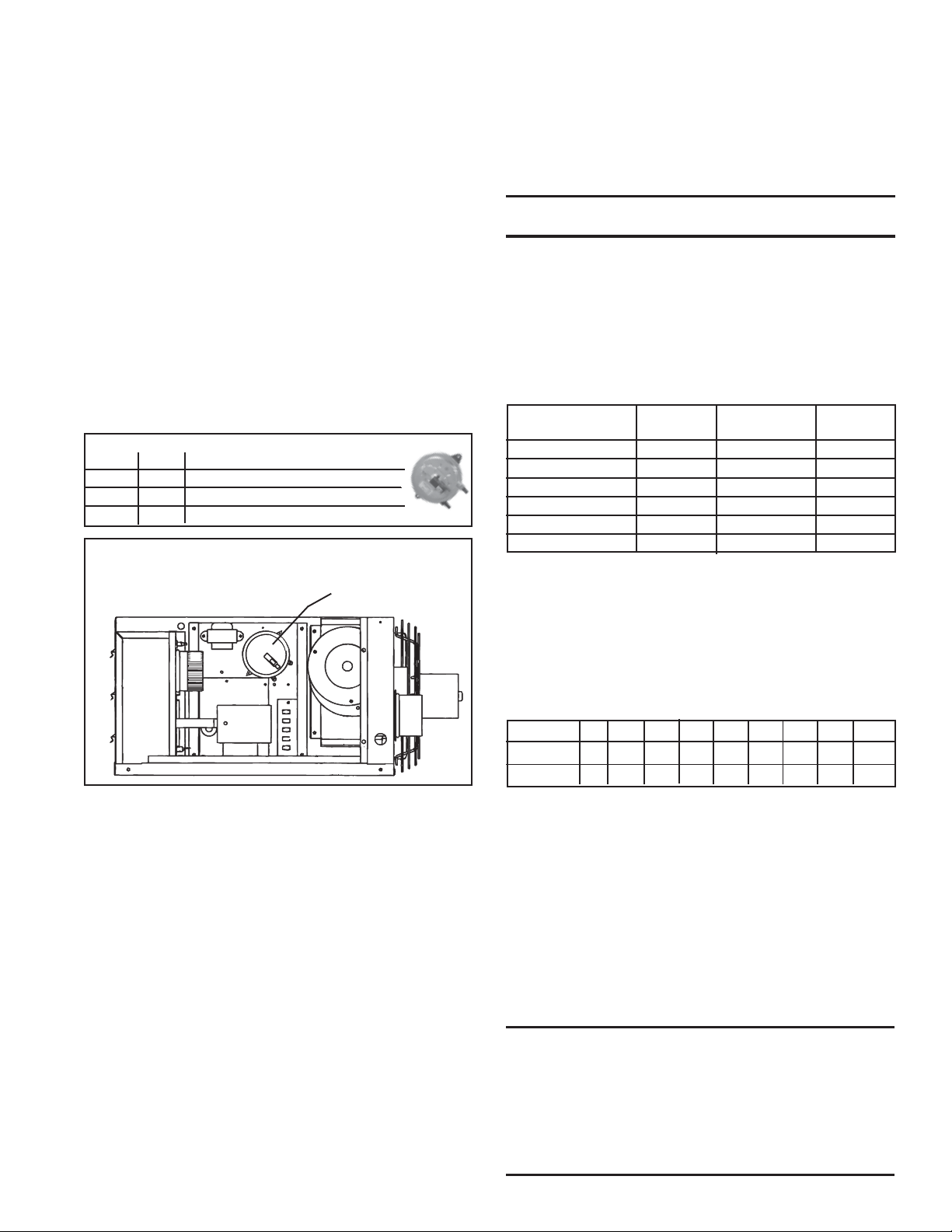
Figure 1 - Model SFT with Access Panel Open showing
Combustion Air Pressure Switch
(flexible combustion air hose removed
for clarity)
Combustion Air
Pressure Switch
When units are located in the center of the space to be heated, the air
should be discharged toward the exposed walls. In large areas, units
should be located to discharge air along exposed walls with extra units
provided to discharge air in toward the center of the area.
At those points where infiltration of cold air is excessive, such as entrance doors and shipping doors, it is desirable to locate the unit so that
it will discharge directly toward the source of cold air from a distance
of 15 to 20 feet (4.5 to 6 M) .
CAUTION: Do not locate the heater where it may be
exposed to water spray, rain, or dripping water.
6. Clearances
This heater must be installed so that the clearances in the table below
are provided for required spacing from combustible construction and
for service and inspection. Clearance to combustibles is defined as the
minimum distance from the heater to a surface or object that is necessary to ensure that a surface temperature of 90°F above the surrounding ambient temperature is not exceeded.
Required Clearances - inches (mm)
Model SFT 45, 100, 125, 250,
60, 75 150, 200 300
Top 1 (25) 6 (152) 6 (152)
Flue Connector 6 (152) 6 (152) 6 (152)
Access Panel 20 (508) 24 (610) 24 (610)
Non-Access Side 1 (25) 6 (152) 6 (152)
Bottom* 1 (25) 1 (25) 1 (25)
Rear 18 (457) 18 (457) 24 (610)
*A Model SFT 45, 60, or 75 installed in a residential garage must be
installed with a minimum clearance above the floor of 18 inches
(457mm). Sizes 100-300 are not certified for residential installations.
Gas
Valve
If the heater is going to be de-rated by adjusting the manifold pressure,
find the label in the owner's envelope. When the adjustment is completed, fill-in the correct pressure setting with permanent marker and
adhere the label to the heater in a conspicuous location close to the gas
valve.
5. Unit Heater Location
For best results, the heater should be placed with certain rules in mind.
In general, a unit should be located from 8 to 12 feet (2.4 to 3.6 M)
above the floor. Units should always be arranged to blow toward or
along exposed wall surfaces, if possible. Where two or more units are
installed in the same room, a general scheme of air circulation should
be maintained.
Suspended heaters are most effective when located as close to the working zone as possible, and this fact should be kept in mind when determining the mounting heights. However, avoid directing the discharged
air directly on the room occupants.
Partitions, columns, counters, or other obstructions should be taken
into consideration when locating the unit heater so that a minimum
quantity of airflow will be deflected by such obstacles.
7. Suspending the Heater
Before suspending the heater, check the supporting structure to be used
to verify that it has sufficient load-carrying capacity to support the
weight of the unit.
Net Weight - lbs and kg
Size 45 60 75 100 125 150 200 250 300
lbs 85 110 120 148 153 216 226 272 294
kg 39 50 54 67 69 98 103 123 133
When the heater is lifted for suspension, support the bottom of the
heater with plywood or other appropriately placed material. If the bottom is not supported, damage could occur.
Determine type of suspension to be used:
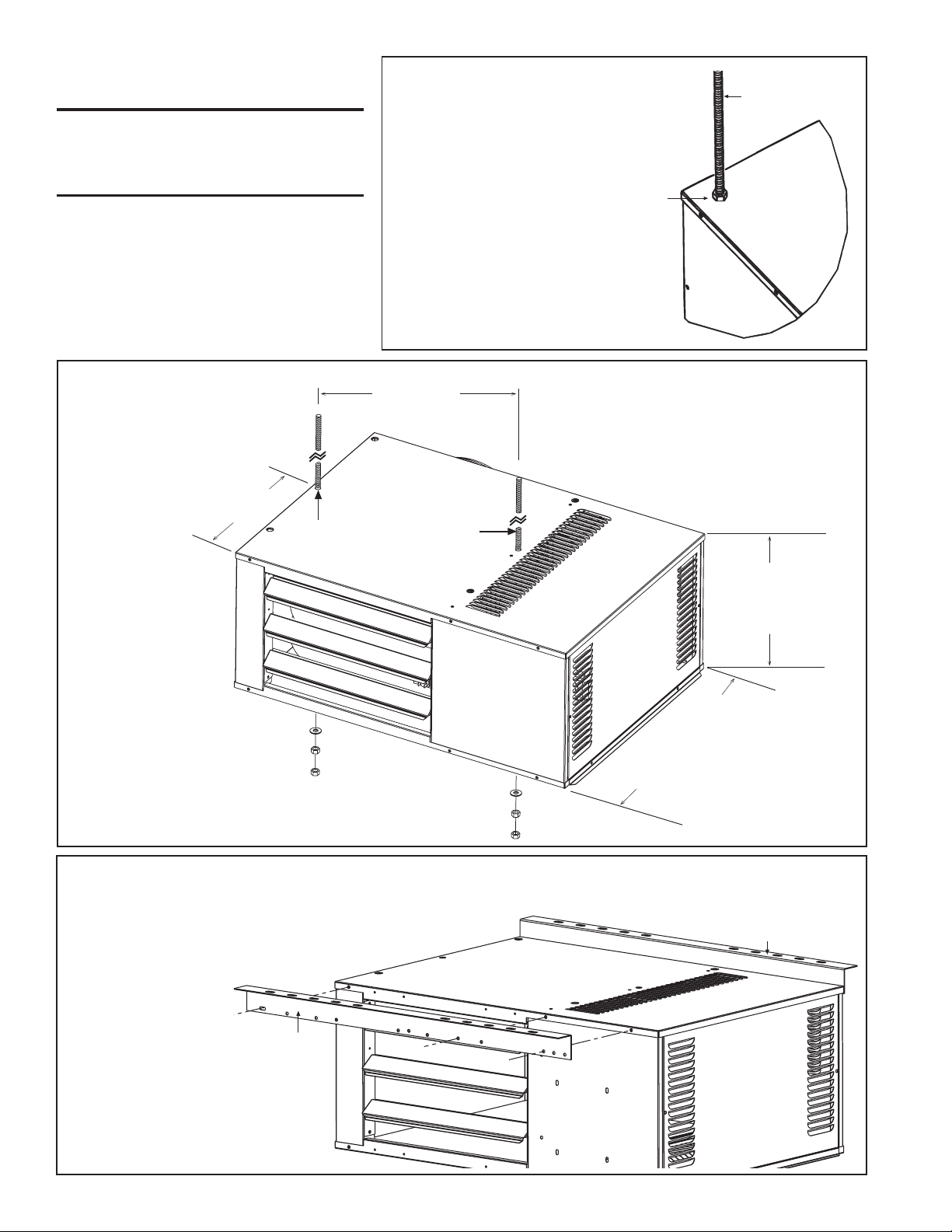
• All Sizes - The heater is equipped with four-point suspension. Two
3/8"-16 threaded nut retainers are located on each side of the heater.
See Dimensions in Paragraph 8 and illustration in Figure 2A.
• Sizes 45, 60, and 75 may be installed with two-point suspension.
Follow the illustrated instructions in Figure 2B, page 4.
• Sizes 45, 60, and 75 may be suspended using an optional ceiling
suspension kit. Refer to Figure 2C. Step-by-step instructions are
included with the option kit.
WARNING: Suspend any size of Model SFT
heater from the threaded nut retainers (Figure
2A). Or , suspend a Size 45, 60, or 75 as illustrated
in Figure 2B or using the Ceiling Suspension Kit
in Figure 2C.
DO NOT suspend any heater from the heater
cabinet panels.
Form RZ -NA-I-SFT, Mfg No. 173474 (Rev 6), Page 3
Page 5
7. Suspending the Heater
(cont'd)
WARNING: Unit must be level for
proper operation. Do not place or add
additional weight to the suspended
heater. See Hazard Levels, page 2.
Figure 2A - Four-point Suspension
(applies to all sizes)
Be sure that the
threaded hanger rods
are locked to the
heater as illustrated.
Recommended
maximum hanger rod
length is 6 feet
(1829mm).
Add a 3/8 nut
to lock the hanger
rod to the heater
3/8 Threaded Rod
Figure 2B - Two-point
Suspension - Applies to
Sizes 45, 60, and 75 only
On the bottom of the heater, use a washer
and double nuts to attach each threaded rod.
Use double nuts. Lock lower nut to upper by
holding upper nut while tightening lower nut.
9-9/16
(243mm)
C
L
5/16 or 3/8 threaded rods
(maximum length above
the heater is 18/457mm )
17-15/16
(456mm)
C
L
Sizes 45 --
12-1/8 (308mm)
Sizes 60/75 --
18-1/8 (591mm)
Sizes 45 --
21-1/4 (540mm)
Sizes 60/75 --
23-1/4 (591mm)
Figure 2C - Suspending with Ceiling Suspension Kit, Option CK22.
When suspending, use a minimum of two anchor points per angle.
NOTES: Quantity of screws used to attach the suspension angles
will vary by heater size and from front to rear of
cabinet. If optional vertical louvers
are being added,
install louvers
after suspension
angles are attached.
Attach suspension angle -
(1) Remove ALL screws
across top edge of cabinet.
(2) Position suspension angle, aligning
holes with same holes emptied in Step (1).
(3) Using ALL screws that were
removed and the same cabinet
holes, attach suspension angle.
Form RZ -NA-I-SFT, Page 4
Suspension angle
attached to rear
of heater
Page 6
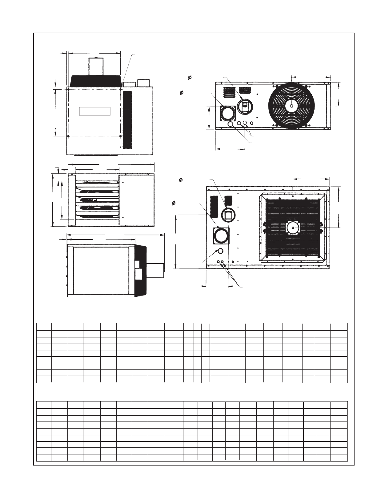
8. Dimensions
Figure 1
U
V
T
Hanger
Location
E
B
F
S
Top View
C
A
4-pt suspension points
3/8-16 cage nuts
Front
View
Air Inlet
Flue Outlet
L
Air Inlet
K
Flue Outlet
L
M
K
P
R
Field wiring connections
Gas Connection 1/2
N
Rear View - Model SFT 45-125
P
R
G
J
H
Right Side
View
M
Gas
Connection
1/2 Sizes 150-200
3/4 Sizes 250-300
N
Rear View - Model SFT 150-300
Field wiring connections
Dimensions (inches ± 1/8")
Size A B C D E F G H J K L M N P R S T U V
45 29-5/8 12-1/8 15 2-5/8 1 10-1/8 26-1/4 21-1/4 3/8 4 3 5-3/4 7-5/8 10 6 18 16 1/ 2 3/4
60-75 29-5/8 18-1/8 15 2-5/8 2-1/2 16-1/8 31-3/8 23-1/4 3 / 8 5 4 10-1/2 8 10 9 18 16 1/ 2 3/4
100 38 22 20-5/8 2-1/4 5 12 33-1/2 25-3/8 1 5 4 11 9-1/2 13-1/4 11 24-1/4 16 1/2 4-5/8
125 38 22 20-5/8 2-1/4 3-5/8 14-3/4 33-1/2 25-3/8 1 5 4 11 9-1/2 13-1/4 11 24-1/4 16 1/ 2 4-5/8
150 38 33 20-5/8 2 6 21 34 25-3/8 1 5 5 21-3/4 9-1/4 13 16-1/2 24-1/4 1 6 1/2 4-5/8
200 38 33 20-5/8 2 4-1/2 24 34 25-3/8 1 5 5 21-3/4 9-1/4 13 16-1/2 24-1/4 16 1/2 4-5/8
250 51-1/4 33 34-1/2 2 4-1/2 21 35-3/8 25-3/8 1 5 5 21-1/2 9-1/4 15-1/8 16-1/2 29-3/8 16 8-1/2 4-5/8
300 51-1/4 33 34-1/2 2 4-1/2 24 35-3/8 25-3/8 1 6 6 22 9-1/4 15-1/8 16-1/2 29-3/8 16 8-1/2 4-5/8
Dimensions (mm ± 3)
Size A B C D E F G H J K L M N P R S T U V
45 752 308 381 67 25 257 667 540 10 102 76 146 194 254 152 457 406 13 19
60-75 752 308 381 67 64 410 797 591 10 127 102 267 203 254 229 457 406 13 19
100 965 559 524 57 127 305 851 645 25 127 102 279 241 337 279 616 406 13 117
125 965 559 524 57 92 375 851 645 25 127 102 279 241 337 279 616 406 13 117
150 965 559 524 51 152 533 864 645 25 127 127 552 241 330 419 616 406 13 117
200 965 559 524 51 114 610 864 645 25 127 127 552 241 330 419 616 406 13 117
250 1302 559 876 5 1 114 533 899 645 25 127 127 546 241 384 419 746 406 216 117
300 1302 559 876 5 1 114 610 899 645 25 152 152 559 241 384 419 746 406 216 117
Form RZ -NA-I-SFT, Mfg No. 173474 (Rev 6), Page 5
Page 7
9. V enting and Combustion Air
All separated combustion, power vented units MUST BE equipped with both combustion air and exhaust piping to the outdoors. The unique
concentric adapter assembly required with this heater allows for both combustion air and exhaust piping with only one horizontal or vertical
penetration hole in the building.
Installation should be done by a qualified agency in accordance with these instructions. The qualified service agency installing this separatedcombustion system is responsible for the installation.
The systems illustrated in this manual are the only venting/combustion air systems approved for a Model SFT heater.
Hazards of Chlorine - The presence of chlorine vapors in the combustion air of gas-fired heating equipment presents a potential corrosion hazard.
Chlorine found usually in the form of freon or degreaser vapors, when exposed to flame will precipitate from the compound, and go into solution
with any condensation that is present in the heat exchanger or associated parts. The result is hydrochloric acid which readily attacks all metals
including 300 grade stainless steel. Care should be taken to separate these vapors from the combustion process. This may be done by wise location
of unit vent terminals with regard to exhausters or prevailing wind directions. Remember, chlorine is heavier than air. This fact should be kept in
mind when determining installation location of these heaters and building exhaust systems.
WARNING: Do not use an existing venting system. This heater requires installation of the combustion
air/vent system ordered with the unit (either Option CC2 or Option CC6).
Specific Venting Requirements (read all before installing)
1. Concentric Adapter Kit (ordered with the heater as either Option CC2 or Option CC6)
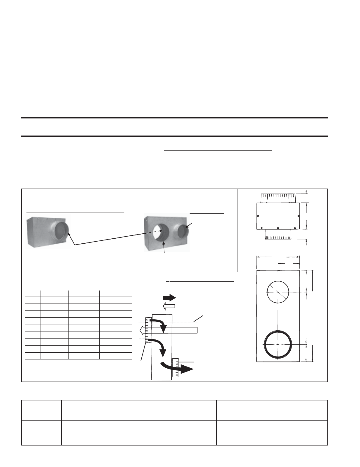
All Model SFT installations require a concentric adapter kit. Each kit includes the concentric adapter box (See Figure 4), a vent terminal cap, and
an inlet air guard or cap. Follow the instructions on pages 7 - 9 to install a horizontal vent/combustion air system (Option CC6). Follow the
instructions on pages 10 - 11 to install a vertical vent/combustion air system (Option CC2).
The vent/combustion air systems illustrated in Figure 6D or 7E are the only venting/combustion air systems appr oved for this heater.
Figure 4A - Concentric Adapter Box Required with all Model SFT Installations
(included in both Option CC2 and Option CC6)
View of Vent Terminal Connection Side
Collar for outside portion of the combustion
air pipe (vent pipe extends through the box
internally concentric to the outside portion
of the combustion air pipe)
View of Heater Connection Side
Collar for
connecting
indoor portion
of the
combustion air
Install rubber
seal for vent pipe
pipe
End View
H
2 (51mm)
6 (152mm)
2 (51mm)
F
Figure 4B - Concentric Adapter Box
Dimensions - inches (mm)
SFT 45-125 150-250 30 0
A 4 (102) 5 (127) 6 (152)
B 4 (102) 4 (102) 5 (127)
C 3 (76) 4 (102) 4 (102)
D 5-1/2 (140) 7-1/2 (191) 7-1/2 (191)
E 3-1/2 (89) 5 (127) 5 (127)
F 4 (102) 4 (102) 5 (127)
G 12 (305) 16-1/2 (419) 16-1/2 (419)
H 8 (203) 8 (203) 10 (254)
J 6 (152) 6 (152) 8 (203)
J = Diameter of the Collar for
attaching the "Outside" Portion of
the Combustion Air Pipe
Top View of the Concentric
Adapter Box Showing Air Flow
= Combustion Air Flow
= Exhaust (Vent) Gas Flow
Field-supplied vent
pipe passes through
the rubber seal and
extends out both sides
of the concentric
adapter box.
A = Diameter of the
Collar for attaching the
Combustion Air Pipe
from the Heater
E
B
D
C
Side View - Side of the
Adapter Box that
Connects to the Heater
2. Type of Pipe (field-supplied)
Vent Pipe - the type of vent pipe required depends on the type of installation.
Type of COMMERCIAL/INDUSTRIAL (Harmonized ANSI Z83.8-1996 RESIDENTIAL (CSA Requirement 10-96)
Installation and Canadian Standard CAN/CGA A 2.6-M96) - Applies to all Applies to Model SFT 45, 60, and 75 ONLY
sizes of Model SFT Heaters
Type of VENT Use either vent pipe approved for a Category III appliance OR Vent pipe approved for a Category III
Pipe Required single-wall, 26-gauge or heavier galvanized (or a material of appliance is required.
equivalent durability and corrosion resistance) vent pipe.
Form RZ -NA-I-SFT, Page 6
G
Page 8
2. Type of Pipe (field-supplied) (cont'd)
Combustion Air Inlet Pipe Between the Heater and the Concentric
Adapter - Sealed, single-wall galvanized pipe is recommended.
Combustion Air Pipe Between the Adapter Box and the Combustion
Air Inlet - The vent pipe is internally concentric to the combustion air
pipe; use single-wall galvanized pipe for the combustion air pipe.
3. Pipe Diameter and Length - ft (M)
Maximum Pipe Length from Heater to Concentric
Adapter - minimum length is five feet (1524 mm)
Model Pipe Diameter Maximum 90° Elbow 45° Elbow
SFT V ent Inlet Air Length Equals* Equals*
45 3" or 4" 3" 30 ft (9.1M) 5 ft (1.5M) 2.5 ft (.8M)
60, 75, 4" or 4" 40 ft 5 ft 2.5 ft
100, 125 5" (12.1M) (1.5M) (.8M)
150, 200 5" 5" 40 ft (12.1M) 5 ft (1.5M) 2.5 ft (.8M)
250 5" 5" 50 ft (15.2M) 5 ft (1.5M) 2.5 ft (.8M)
300 6" 6" 50 ft (15.2M) 5 ft (1.5M) 2.5 ft (.8M)
*Reduce maximum length by this amount for each elbow .
Concentric Pipes (the vent pipe runs through the concentric adapter
extending internally concentric through the outdoor portion of the combustion air pipe) - Sizes 45 - 250 require 6" diameter combustion air pipe
for the outdoor portion and a 4" vent pipe through the concentric adapter
to the terminal; Size 300 requires an 8" diameter combustion air pipe for
the outdoor portion and a 5" diameter vent pipe through the concentric
adapter to the terminal. Refer to the installation instructions for the concentric adapter kit for length requirements.
4. Joints/Seals
In Pipe Runs - provide pipe as specified in Requirement No. 2 and make
joints as follows:
• If using single wall, 26-gauge or heavier galvanized pipe, secure
slip-fit pipe connections using sheetmetal screws or rivets. Seal all
joints. Seal combustion air pipe with pressure sensitive tape ordinarily used for warm-air ductwork. Wrap two full turns around each
joint. Seal flue exhaust pipe with either tape suitable for 550°F (such
as Option FA1, P/N 98266) or high-temperature (450°F) silicone sealant.
• If using Category III vent pipe, follow the pipe manufacturer's in-
structions for joining and sealing vent pipe sections.
In Concentric Pipes (outdoor portion) from the Adapter Box to Air
Inlet and Vent Terminal - Follow the instructions for concentric adapter
kit (pages 7 - 9 for a horizontal system or pages 10 - 110 for a vertical
system).
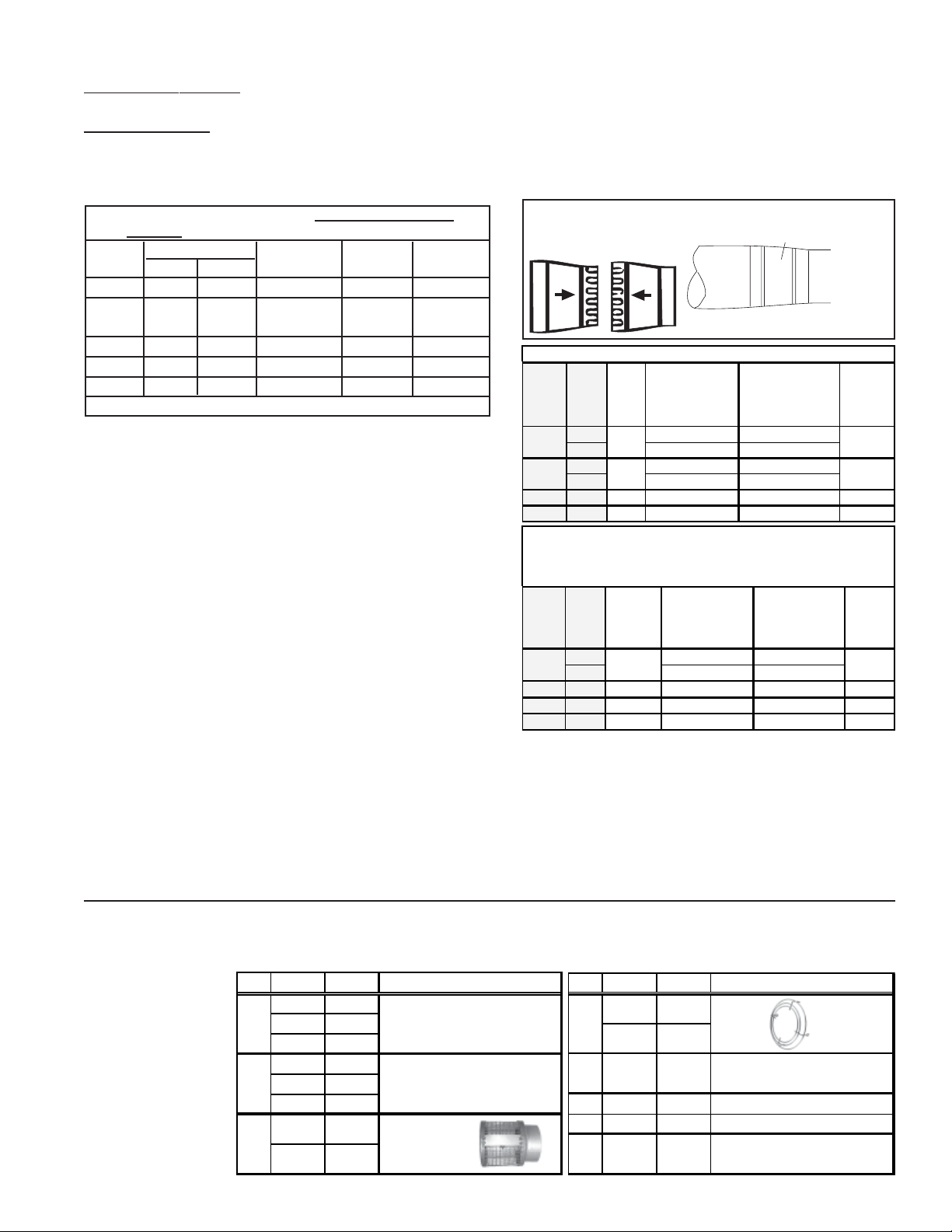
Joints Requiring Taper-type Connections (See Figure 5 and Tables
that follow) - When the diameter of the pipe in the inlet air or vent pipe
run is different from the connections at either the heater or the concentric adapter box, the joint must be made with a taper-type pipe
connector.
When the diameter change is at the heater, install the connector at
the collar or no more than 6" (152mm) from the heater.
When the diameter change is at the concentric adapter box, install
the connector no more than 6" (152mm) from the opening or collar
on the concentric adapter box.
Figure 5 - Use taper-type connections (see where
they are required below)
Reducer
Airflow
Tap er-type connector(s) required in the
SFT
Size
45
60-125
150-250 5" dia
300 6" dia
A taper-type connector is always
AIR PI PE
concentric adapter. When using 4" pipe, install th e r ed u cer at the heater. Other
sizes do n ot r equire a taper-type connection in the inlet air pip e r un.
Size
SFT
45
60-125 4" dia
150-250 5" dia
300 6" dia
Enlarger
Airflow
Venter
Vent
Pipe
Run
3" dia 4" to 3" Reducer 3" to 4" Enlarger
4" dia
4" dia 5" to 4" Reducer
5" dia
on Mo d el SFT 45. When using 3" pip e, install the reducer at t he
Inlet
Air
Pipe
3" dia 4" to 3" Reducer
4" dia
Reducer
Collar
to join venter collar
on
Heater
4" dia
5" dia
5" dia None
6" dia None
Air Inlet
Collar on
Concentric
Adapter
4" dia 3" dia
4" dia None None 4" dia
5" dia None None 5" dia
6" dia None None 6" dia
Reducer
to join concentric
adapter collar and
Taper-type Connector
Secure joints with sheetmetal
screws and seal.
VENT PIPE RUN
required
and pipe
None None
None
required
required
pipe
None
Taper-type
connection
to join different
diameter vent pipes
5" to 4" Reducer
5" to 4" Reducer
6" to 5" Reducer
in the indoor portion of the
Reducer
t o jo in heater
collar and pipe
4" to 3" Reducer
required
None
None
Either collar
or smaller
diameter pipe
req u ire d
Vent Pip e
through
Adapter
Box
4" dia
4" dia
4" dia
5" dia
INLET
Inlet Air
Collar at
Heater
5. Support
Support horizontal runs every six feet (1829mm); do not rely on the
heater or the adapter box for support of either horizontal or vertical
pipes. Use non-combustible supports on vent pipe.
6. Clearance
Do not enclose the vent pipe or place pipe closer than 6" (152mm)
to combustible material.
Instructions and Requirements for Installing a Horizontal Vent T erminal/Combustion Air
Inlet (Requires Concentric Adapter Kit, Option CC6)
Horizontal Vent
Terminal/Combustion
Air Package
(Option CC6)
includes:
Qty Size P/N Description
1 45-125 157157
150-250 157158
300 82131
1 45-125 155118
150-250 155392
300 68404
1 45-250 155096 Screened
300 53316
Complete Horizontal Vent Kit
(Same as Option CC6)
Concentric Adapter Box
Assemby (See Figure 3A)
Exhaust Assy
Qty S ize P/N Description
1 45-250 151755 Inlet
300 124940
4 45-300 37661
1 45-250 164492 4" I.D. Rubbe r Seal
1 300 1 64493 5" I.D. Rubber Sea l
1 45-300 53335
Form RZ -NA-I-SFT, Mfg No. 173474 (Rev 6), Page 7
Guard
#10-16 x 1/2" lg Screws to
attach the in let guard
Tube of High Temperature
(450°F) Silicon e Sealant
Page 9
9. Venting and Combustion Air (cont'd)
Installation Requirements for Option CC6 (cont'd)
Field-supplied installation requirements:
• Thimble (a thimble is not required if wall is of non-combustible
construction)
• Flashing
• Vent pipes (see requirements on pages 6-7)
• Combustion air pipes (see requirements on page 7)
• Mounting brackets for concentric adapter box (or box may be
mounted flush, depending on building construction)
• Taper-type reducers and/or enlargers as required (see requirements on page 7)
Installation Instructions for Option CC6
1. Determine the location on the outside wall for the vent terminal.
In most applications, the terminal would be on a level with the heater
mounting height as shown in Figure 6D. Allow 1/4" per foot downward pitch for condensate drain.
The distance of the termination of the horizontal vent from adjacent
public walkways, adjacent buildings, openable windows, and building
openings must be in accordance with local codes or, in the absence of
local codes, must conform with National Fuel Gas Code Z223.2. Local
codes supersede all provisions in these instructions and in the National
Fuel Gas Code. Minimum clearances for the horizontal vent terminal
are shown in the table below.
Structure
Forced air inlet within 10
ft (3.1m)
Combustion air inle t of
another app liance
Door, window, or gravit y
air inlet (any building
opening)
Electric meter, ga s me ter *
and relief equipment
Gas regulator * 3 ft (0.9m)
Adjoining building or
parapet
Adjacent public walkways 7 ft (2.1m) above
Grade (gro und level) 7 ft (2.1m) above
Products of combustion can cause discoloring of some building finishes and deterioration of masonry materials. Applying a clear silicone
sealant that is normally used to protect concrete driveways can protect
masonry materials. If discoloration is an esthetic problem re-locate the
vent or install a vertical vent.
Minimum Clearances for Vent Termination
Locat ion (all directions u nless specified)
3 ft (0.9m) above
6 ft (1.8m)
4 ft (1.2m) horizontally
4 ft (1.2m) below
1 ft (30cm) above
4 ft (1.2m)
horizontally
6 ft (1.8m)
*Do not terminate the vent
directly above a gas meter or
service regulator.
WARNING: All vent terminals must be positioned
or located away from fresh air intakes, doors and
windows to preclude combustion products from
entering occupied space. See Hazard Levels, page 2.
2. Prepare clearance hole through the outside wall for a 6" diameter
pipe (Sizes 45-250) or an 8" diameter pipe (Size 300). Outside wall
construction thickness should be between 1" (25mm) minimum and
30" (762mm) maximum. The larger diameter combustion air pipe serves
as clearance for the vent pipe on non-combustible construction. A
thimble may or may not be required depending on wall construction
and/or local codes.
3. Prepare the concentric adapter box.
3a) Determine whether field-supplied brackets are required. The
box must be positioned so that the distance from the outside of the
wall to the box is a minimum of 12" (305mm). Maximum distance
is 60" (1524mm). If brackets are used, box should be angled slightly
to allow for downward pitch of pipes. If used, attach brackets securely; do not leave any unsealed holes in the adapter box. If brackets
are not used, when the box is installed, it should be against the
wall.
3b) Install the rubber seal and the vent pipe. Locate the vent pipe
opening and place the rubber seal around and over the edge of the
metal.
Worksheet - Determine Length of
Vent Pipe through the Box
inches mm
Heater Side (max if + 6 152
different diameters)
Width of Box + 6 152
Bracket Length + __ ___
Width of Wall + __ ___
T erminal Side (min) + 18 457
Length of Pipe =
Lubricate the seal and pipe with liquid soap or a rubber lubricant.
(Installation Tip: Spray cooking oil works well as a lubricant for
this task.)
Being sure the pipe is in the proper flow direction, slide the end
through the box and push it out through the rubber seal. Push evenly
using caution not to displace the seal from its position on the edge
of the hole. If the rubber seal moves, slide the pipe back slightly,
re-position the seal, and slide the pipe through again.
Determine the length of the section of vent pipe by adding the
requirements. The vent pipe
must extend a maximum of 6"
(152mm) on the heater side (if
a reducer is required); plus 6"
(152mm) through the box; plus
bracket length; plus the width
of the wall; plus a minimum of
18" (457) on the outside (if the
inlet pipe extends 2" (51mm)
beyond the wall).
6A
Install the vent pipe
by inserting it into the
terminal side of the
box and pushing it out
through the seal on
the heater side.
NOTE: Be sure flow
direction of vent pipe
is correct.
Form RZ -NA-I-SFT, Page 8
Field-supplied mounting brackets
Combustion air pipe
Seal the seam in the vent pipe.
Vent Flow
16 (406mm) minimum
Combustion
Air Flow
2 (51mm)
approx plus
wall thickenss
Concentric
Adapter Box
Collar for combustion
air pipe.
Install rubber seal in
vent pipe opening.
Vent Pipe - if a
reducer is required
in the vent pipe;
the connection
must be no more
than 6 (152mm)
from the box.
Page 10

s
a
o
Position the vent pipe so that it will extend a minimum of 16" past
the end of the combustion air pipe. See Figure 6A. If a reducer is
required, a maximum of 6" (152mm) of vent pipe should extend
out the heater side. Any time the pipe is re-positioned, re-check the
seal to be sure that it has not rolled. Adjust the pipe and seal until
the pipe is the correct length on each side of the box and the seal is
over the edge of the hole and tight to the entire circumference of
the pipe.
3c) Attach the outside portion of the combustion air pipe to the
box. Determine the length by measuring the bracket length (if brack-
ets are used), plus the wall thickness, plus 2" (51 mm). The inlet air
pipe should extend beyond the outside wall approximately 2"
(51mm).
Attach the inlet air pipe to the collar of the concentric adapter with
sheetmetal screws, being careful not to penetrate the vent pipe.
4. Attach the concentric adapter box
to the wall. Insert the vent pipe and com-
bustion air pipe through the wall. Push
the concentric adapter box flush against
the inside wall or attach to the wall with
the field-supplied brackets. Caulk or
flash inlet air pipe on the outside wall.
Flash or caulk the air
inlet pipe
on the
outside
wall.
6B
Flashing is field-supplied.
5. Slide the inlet guard over the end of the vent pipe and position it
on the end of the combustion air pipe. See Figure 6C. Attach the guard
to the inlet air pipe with the four 1/2" lg screws provided.
6. Position the vent cap on the end of the vent pipe. Align the cap so
that its baffle strips are positioned on the horizontal and vertical
centerlines (See Figure 6C). Attach the exhaust cap to the vent pipe
with sheetmetal screws.
First, attach the inlet
air guard;
Second, attach the
exhaust cap
Inlet Air
Guard
6C
IMPORTANT: Install
exhaust cap with baffles
positioned on horizontal
and vertical centerlines as
illustrated.
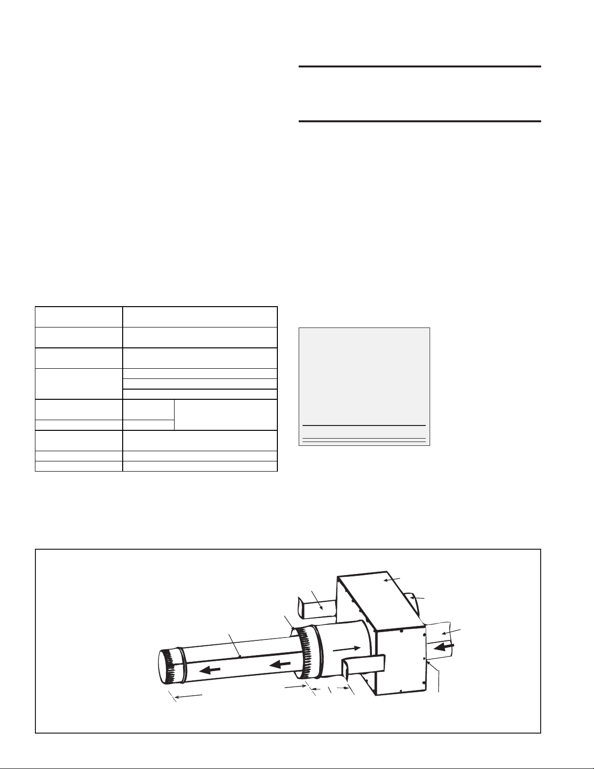
7. Horizontal vent terminal/combustion air inlet Option CC6 is installed
and ready for connection to the heater. Refer to Figure 6D and verify
compliance with all requirements illustrated.
8. Connect the Concentric Adapter Box to the Heater - Use the pipe
specified and joints required for type of pipe. If collar or opening at the
heater or adapter are different diameters from the pipe (use only diameters allowed on page 7), make joint connection with field-supplied
taper-type reducer or increaser .
A minimum of 12" (305 mm) of straight pipe is required at the venter
outlet.
Due to the high temperature, do not enclose the exhaust pipe or place
pipe closer than 6" (152 mm) to combustible material.
Installation of the horizontal vent and combustion air system on your
separated-combustion unit is complete. Verify that all installation requirements are met. Continue to Paragraph 9.
Side
View
Adjoining
Building
3 ft (914mm)
6ft (1829mm)
minimum
3 ft (914mm)
Building Overhang
Vent Pipe
- PITCH
minimum
6-15/16 (176mm)
Thimble
IMPORTANT NOTE: Exhaust cap must be installed
are positioned on horizontal and vertical centerlines
minimum
Building Projection
DRAIN
16(406mm)
minimum
24(610mm)
maximum
Wall
TO
Top
View
Figure 6D - Installation of a Typical Separated-Combustion Unit with
Concentric Adapter B
Combustion Air Pipe
(PITCH TO DRAIN)
60 (1524mm)maximum
12 (305mm) minimum
Wall
Inlet
Air
Guard
Horizontal Vent and Combustion Air Pipes (Option CC6)
"Through-the-W all" View of a typical
installation of a horizontal vent/inlet air
terminal and concentric adapter
(Option CC6)
Concentric Adapter Box
Combustion Air Pipe (seal joints)
Seal vent pipe joints; see
Requirement No. 4 on page 7.
Screened
Exhaust Cap
Vent (Flue Exhaust) Pipe
Maximum Length (See
Requirement No. 3 on page 7.)
Minimum length is 5 ft (1.5M).
Form RZ -NA-I-SFT, Mfg No. 173474 (Rev 6), Page 9
Page 11
9. Venting and Combustion Air (cont'd)
Installation Requirements for Option CC2
Instructions and Requirements for Installing a Vertical Vent Terminal/Combustion Air Inlet
(Requires Concentric
Adapter Kit,
Option CC2)
Q ty S ize P/N Des cripti o n
1 45-125 157155
150-250 157156
300 54444
1 45-125 155118
150-250 155392
300 68404
1 45-250 155631 Exhaust
300 53326
Comp lete Vert ical Ven t Kit
(Sam e as Option CC2)
Concentric Adapt er Box
Assembly (See Figure 3A)
Terminal
Qty S ize P/N De s cripti o n
1
45-250 155635
300 53330
1 45-250 164492 4" I.D. Rubber Seal
300 164493 5" I.D. Rubber Seal
1 45-300 53335
Combustion
Air Inlet
Tube of High Temperature
(450°F) Silicone Sealant
Field-supplied installation requirements:
• Thimble (a thimble is not required if roof is of non-combus-
tible construction)
• Flashing
• Vent pipes (see requirements on pages 6-7)
• Combustion air pipes (see requirements on page 7)
• Mounting brackets for concentric adapter box (or box may be
mounted flush, depending on construction)
• Joint connection reducers and/or enlargers (see requirements
on page 7)
Installation Instructions for Option CC2
1. Determine the location for the vent terminal on the roof,
allowing room for the concentric adapter box inside. A thimble
may or may not be required depending on building construction
and/or local codes. Prepare a hole through the roof for the combustion air pipe. The air inlet pipe must be flashed or sealed to
the roof. Flashing is to be supplied by the installer as required by
roof construction and/or codes.
W ARNING: All vent terminals must be positioned
or located away from fresh air intakes, doors and
windows to preclude combustion products from
entering occupied space. See Hazard Levels, page
2.
2. Prepare the concentric adapter box.
2a) Determine whether field-supplied brackets are required.
If used, attach brackets securely; do not leave any unsealed
holes in the adapter box. If brackets are not used, when installed the box should be against the roof.
2b) Install the rubber seal and the vent pipe. Locate the vent
pipe opening and place the rubber seal around and over the
edge of the metal.
Worksheet - Determine Length of
V ent Pipe through the Box
inches mm
Heater Side (max if + 6 152
different diameters)
Width of Box + 6 152
Bracket Length + __ ___
Width of Roof + __ ___
Inlet Pipe Height + __ _ _ _
T erminal Side (min) + 22 559
Length of Pipe =
Lubricate the seal and pipe with liquid soap or a rubber lubricant. (Installation Tip: Spray cooking oil works well as a lu-
Form RZ -NA-I-SFT, Page 10
Determine the length of
the section of vent pipe
by adding the requirements. The vent pipe
must extend a maximum
of 6" (152mm) on the
heater side (if a reducer
is required); plus 6"
(152mm) through the
box; plus bracket length;
plus the width of the roof;
plus the length of the
outer inlet air pipe; plus
a minimum of 22"
(559mm).
bricant for this task.) Being sure the pipe is in the proper flow direction,
slide the end through the box and push it out through the rubber seal.
Push evenly using caution not to displace the seal from its position on
the edge of the hole. If the rubber seal moves, slide the pipe back slightly ,
re-position the seal, and slide the pipe through again. When the vent pipe
is in its final position, re-check the seal to be sure that it has not rolled in.
Adjust the pipe and seal until the seal is in the correct position on the
edge of the hole and tight to the entire circumference of the pipe.
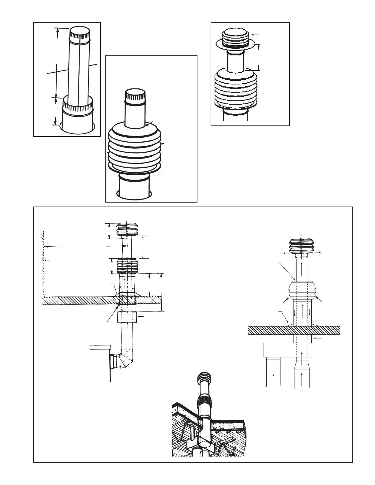
Position the vent pipe so that it will protrude a minimum of 22" (559mm)
past the end of the combustion air pipe. See Figure 7A.
If a taper type connection is required in the vent run, no more than 6"
(152mm) of vent pipe should extend out the heater side of the adapter
box.
2c) Attach the outside portion of the combustion air pipe to the box.
Determine the length of the combustion air pipe so that dimension "X"
(Figure 7A) is equal to the roof thickness, plus snow depth and ridge or
parapet clearance, but does not exceed 60" (1524 mm). Attach the combustion air pipe to the collar with sheetmetal screws being careful not to
penetrate the vent pipe.
"X" is the length of combustion
air pipe required through and
above the roof
"X" must equal roof thickness
plus clearance required for
anticipated snow plus ridge and/or
parapet
"X" must not
exceed 60"
(1524mm)
Field-supplied
mounting brackets
Concentric
Adapter Box
Collar for
combustion
air pipe.
Vent Pipe - when a taper-type
vent pipe; it must be no more
than 6(152mm) from the box.
Seal the seam in
the vent pipe.
reducer is required in the
Install the vent pipe
by inserting it into
the terminal side of
the box and pushing
it out through the
seal on the heater side
NOTE: Be sure
ent Flow
V
vent flow direction
is correct.
Combustion
air pipe
Air Flow
Combustion
Install seal
in vent pipe
opening
7A
Page 12
7B
22"
(559mm)
minimum
Snow
Clearance
4. Slide the combustion air inlet over the vent pipe and fas-
ten collar to the end of the combustion air pipe with sheetmetal
screws (See Figure 7C). Seal
joint at top between vent pipe
and combustion air inlet with
silicone sealant to prevent water leakage.
3. Attach the concentric adapter . Insert the
vent pipe and combustion air pipe up
through the roof and secure the adapter box.
Flash the combustion air pipe to the outside of the roof as required.
7C Slide combustion air inlet
over the vent pipe and fasten
to the end of the combustion
air pipe.
Seal top joint
(between the vent
pipe and air inlet)
with silicone.
Install fieldsupplied
flashing at
roof opening.
7D
Exhaust
Terminal
5. Attach the exhaust ter minal with sheetmetal
screws (See Figure 7D).
6. Vertical vent terminal/
12" (305mm)
minimum
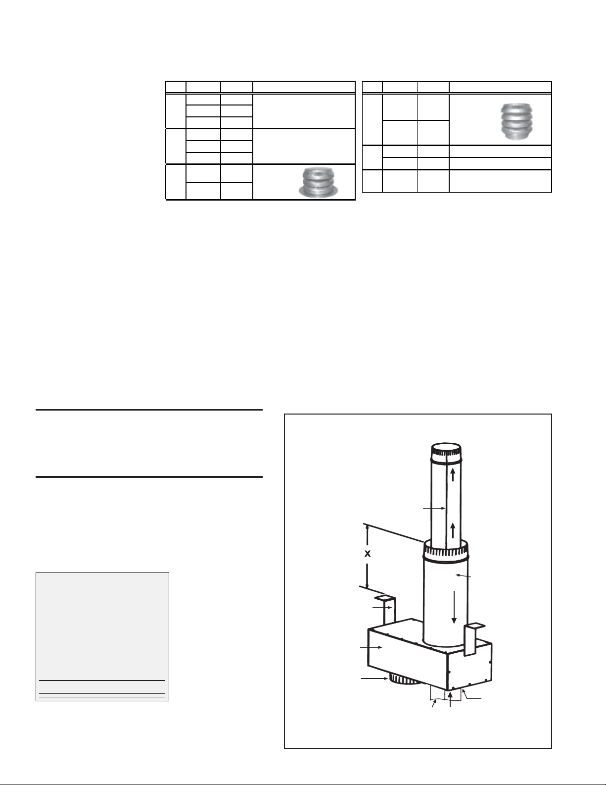
combustion air inlet is installed and ready for connection to the heater.
Refer to Figure7E and
verify that all installation
requirements are met.
7) Connect Concentric Adapter to the Heater - Use the pipe
specified and joints required for type of pipe. If collars at the
heater or the collar or opening on the adapter are different diameters from the pipe (use only diameters listed on page 7), make
joints with field-supplied taper-type reducer or increaser.
A minimum of 12" (305 mm) of straight pipe is requir ed at the
venter outlet.
Due to the high temperature, do not enclose the exhaust pipe or
place pipe closer than 6" (152 mm) to combustible material.
Installation of the vertical vent and combustion air system on your
separated-combustion unit is complete.
Figure 7E - Installation of Separated-Combustion Unit with Vertical Vent and Combustion Air Pipes (Option CC2)
Rear View
Seal with high
temperature silicone
rubber sealant supplied
with the kit.
supplied)
Roof
Termina
Combustion
Air Inlet
Flashing
(field
Concentric
Adapter
Ven t
l
Flue
Exhaust
(Vent )
Pipe
Combustion
Air Pipe
6 ft (1829mm) minimum
Wall or
Adjoining
Building
Roof
9-3/8
(238mm)
11 (279mm)
Flashing
(field
supplied)
Thimble
12 (305mm)
18(457mm)
minimum
See No 4, page 7,
for requirements
and use of tapertype connectors.
Concentric
Adapter
5 ft (1524mm)
maximum (Size
according to
anticipated
snow depth.)
Side View
Vent Pipe
(See
requirements
on page 7.)
Vent Pipe - A minimum of 12
(305mm) of straight pipe is
recommended between the
heater outlet and the elbow.
Combustion
Air Pipe
(See requirements
on page 7.)
"Through-the-Roof" View of a
typical installation of a vertical vent/
inlet air terminal and concentric
adapter (Option CC2)
Form RZ -NA-I-SFT, Mfg No. 173474 (Rev 6), Page 11
Page 13
From Gas Supply
From
Gas
Supply
6 Drip Leg
NOTE:
Connections
shown are by
the installer.
To Controls
Manual
Gas Valve
Immediately upstream of the gas
supply connection, install a manual
shutoff valve with a 1/8 NPT
plugged tap accessible for test
gauge connection.
Ground Joint Union
9. Gas Piping and Pressures
WARNING: This appliance is equipped for a
maximum gas supply pressure of 1/2 pound, 8
ounces, or 14 inches water column. Supply
pressure higher than 1/2 pound requires
installation of an additional lockup-type service
regulator external to the unit.
PRESSURE TESTING SUPPL Y PIPING
T est Pr essur es Above 1/2 PSI: Disconnect the heater and manual
valve from the gas supply line which is to be tested. Cap or plug
the supply line.
Test Pressures Below 1/2 PSI: Before testing, close the manual
valve on the heater.
All piping must be in accordance with requirements outlined in the
National Fuel Gas Code ANSI/Z223.1a (latest edition), or CAN/CGAB149.1 and B149.2 (See Paragraph 1). Gas supply piping installation
should conform with good practice and must comply with local codes.
Unit heaters are orificed for operation with natural gas having a heating value of 1000 (± 50) BTUH per cubic ft or propane gas with a
heating value of 2550 BTUH per cubic ft. If the gas at the installation
does not meet these specifications, consult the factory for proper orificing.
Pipe joint compounds (pipe dope) shall be resistant to the action of
liquefied petroleum gas or any other chemical constituents of the
gas being supplied.
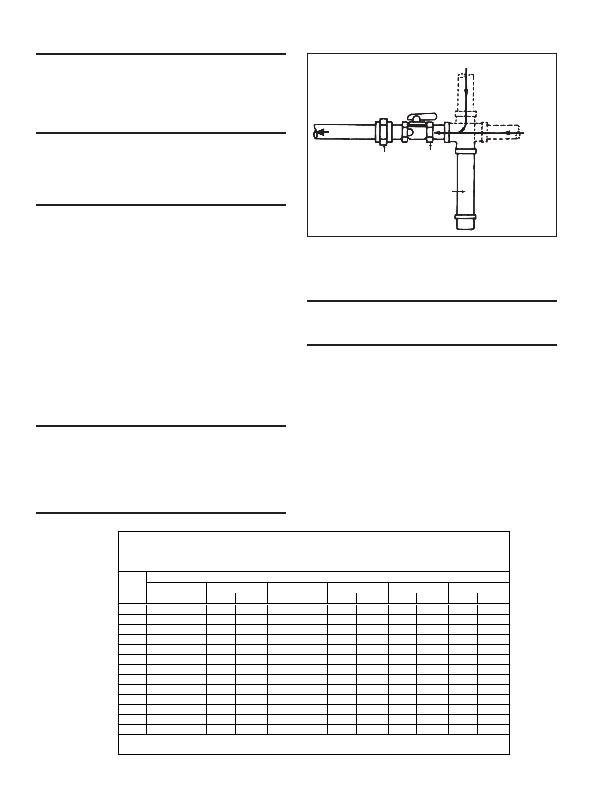
Install a ground joint union and manual shut-off valve upstream of the
unit control system, as shown in Figure 8. The 1/8" plugged tapping in
the shut-off valve provides connection for a supply line pressure test
gauge. The National Fuel Gas Code requires the installation of a trap
with a minimum 3" drip leg. Local codes may require a minimum drip
leg longer than 3" (typically 6").
Gas connection is 1/2" for Sizes 45-200 and 3/4" for Sizes 250-300.
Leak-test all connections by brushing on a leak-detecting solution.
WARNING: All components of a gas supply
system must be leak tested prior to placing
equipment in service. NEVER TEST FOR
LEAKS WITH AN OPEN FLAME. Failure to
comply could result in personal injury , property
damage or death.
Figure 8 - Supply
Piping Connection
Manifold Gas Pressure Setting
Measuring or derating manifold gas pressure cannot be done until the
heater is in operation. It is included in the steps of the "Check-TestStart" procedure in Paragraph 18. The following instructions and warnings apply .
WARNING: Manifold gas pressure must never
exceed 3.5" w.c. for natural gas and 10" w.c. for
propane gas.
For Natural Gas: When the heater leaves the factory , the combination
gas valve is set so that the manifold gas pressure is regulated to 3.5"
w.c. Inlet supply pressure to the valve for natural gas must be a minimum of 5" w.c. or as noted on the rating plate and a maximum of 14"
w .c.
For Propane Gas: When the heater leaves the factory, the combination gas valve is set so that the manifold gas pressure is regulated to
10" w.c. Inlet supply pressure to the valve for propane gas must be a
minimum of 11" w.c. and a maximum of 14" w.c.
Before attempting to measure or adjust manifold gas pressure, the inlet
supply pressure must be within the specified range both when the heater
is in operation and on standby. Incorrect inlet pressure could cause
excessive manifold gas pressure immediately or at some future time. If
natural gas supply pressure is too high, install a regulator in the supply
line before it reaches the heater. If natural gas supply pressure is too
low, contact your gas supplier.
Sizing a Gas
Supply Line
Form RZ -NA-I-SFT, Page 12
Cubic Feet per Hour based on 0.3" w.c. Pressure Drop
Specific Gravit y for Natural Gas -- 0.6 (Natural Gas -- 10 00 BTU/Cub i c Ft)
Specific Gravity for Pr op ane Gas -- 1.6 (Propane Gas -- 2550 BTU/Cubic Ft)
Length Diam eter of Pipe
of 1/2" 3/4" 1" 1-1/4" 1-1/2" 2"
Pip e Natural Propane Natural Propane Natural Propane Natural Propane Natural Propane Natural Propane
20' 92 56 190 116 350 214 730 445 1100 671 2100 1281
30' 73 45 152 93 285 174 590 360 890 543 1650 1007
40' 63 38 130 79 245 149 500 305 760 464 1450 885
50' 56 34 115 70 215 131 440 268 670 409 1270 775
60' 50 31 105 64 195 119 400 244 610 372 1105 674
70' 46 28 96 59 180 110 370 226 560 342 1050 641
80' 43 26 90 55 170 104 350 214 530 323 990 604
90' 40 24 84 51 160 98 320 195 490 299 930 567
100' 38 23 79 48 150 92 305 186 460 281 870 531
125' 34 21 72 44 130 79 275 168 410 250 780 476
150' 31 19 64 39 120 73 250 153 380 232 710 433
175' 28 17 59 36 110 67 225 137 350 214 650 397
200' 26 16 55 34 100 61 210 128 320 195 610 372
Not e: When sizin g supply lines, consider poss i bilities of future expansion and increased requ i rements .
Refer to National Fuel Gas Code for additional information on line sizing.
Capacity of Piping
Page 14
Instructions on How to Check Manifold
Pressure (can only be done after heater is
installed):
1) With the manual valve positioned to prevent flow to the main burners, connect a manometer to the 1/8" pipe outlet pressure tap in the
valve. NOTE: A manometer (fluid-filled gauge) is recommended rather
than a spring type gauge due to the difficulty of maintaining calibration of a spring type gauge.
2) Open the valve and operate the heater. Measure the gas pressure to
the manifold. Normally adjustments should not be necessary to the
factory preset regulator.
If adjustment is necessary, set pressure to correct settings by turning
the regulator screw IN (clockwise) to increase pressure. Turn regulator
screw OUT (counterclockwise) to decrease pressure.
Derating by Manifold Pressure Adjustment for
High Altitude Operation
If the heater is being installed above 2000 ft (610M) and it was determined in Paragraph 5 that derating by manifold pressure adjustment is
permissible, follow the instructions below.
Instructions for Derating a Heater by Adjusting Manifold
Pressure (The heater must be factory-equipped for sea
level operation.)
1. Check the rating plate to be certain that the heater is equipped for
sea level operation. Do not attempt to derate by manifold gas pres-
sure adjustment if the heater is factory equipped for high altitude.
2. Determine the required manifold pressure for the elevation where
the heater will be operating. If unsure of the elevation, contact the
local gas supplier.
Manifold Pressure Settings by Elevation
Altitude Natural Gas Propane Gas
Feet Meters (inches W.C.) (inches W.C.)
0- 2000 1-610 3.5 10.0
2001-3000 911-915 2.8 7.7
3001-4000 916-1220 2.5 7.1
4001-5000 1221-1525 2.3 6.4
5001-6000 1526-1830 2.1 5.8
6001-7000 1831-2135 1.9 5.2
7001-8000 2136-2440 1.7 4.6
8001-9000 2441-2745 1.5 4.1
3. With the manual valve positioned to prevent flow to the main burners, connect a manometer to the 1/8” pipe outlet pressure tap in the
valve. Use a fluid-filled manometer that is readable to the nearest
tenth of an inch w.c.
4. Remove the cap from the pressure adjusting screw and adjust the
manifold pressure to the pressure setting selected from the table.
Cycle the main burners once or twice to properly seat the adjustment spring in the valve.
Re-check the pressure. If necessary, re-adjust the pressure. When
the pressure is correct, remove the manometer and replace the cap.
Check for leaks at the pressure tap fitting.
5. With the heater operating determine that the inlet pressure to the
heater for natural gas is between 5 and 14 inches. w.c. and for propane between 10 and 14 inches w.c. Take this reading as close as
possible to heater (Most heaters are now equipped with gas valves
that have an inlet pressure tap.) If the inlet pressure is not within
the specified range, the inlet pressure must be corrected and Steps
3 and 4 repeated.
6. If altitude is above 6000 ft (1830M), verify that the pressure switch
has been changed.
High Altitude Combustion Air Pressure Switches
SFT P/N Description
45-75 173316 Orange Label, -.55", #PPS10143-2908
100-125 173315 Gray Label, -.35", #PPS10143-2907
150-300 173312 White Label, -.60", #PPS10143-2904
7. Find the Manifold Pressure Adjustment label in the plastic bag that
contained these instructions. Using a permanent marker, fill-in the
pressure setting. Adhere the label on the heater near the gas valve
so that it is conspicuous to someone servicing the valve and/or the
heater.
1 1. Electrical Supply and
Connections
All electrical wiring and connections, including electrical grounding
MUST be made in accordance with the National Electric Code ANSI/
NFPA No. 70 (latest edition) or, in Canada, the Canadian Electrical
Code, Part I-C.S.A. Standard C22.1. In addition, the installer should
be aware of and comply with any local ordinances or gas company
requirements.
Check the rating plate on the heater for the supply voltage and current
requirements. A separate line voltage supply should be run directly
from the main electrical panel to a fused disconnect switch located
near the heater. All external wiring must be within approved conduit
and have a minimum temperature rise of 60°C. Conduit from the disconnect switch to the heater must be run so as not to interfere with the
service panels of the heater.
The electrical supply and control wiring enter at the rear of the heater
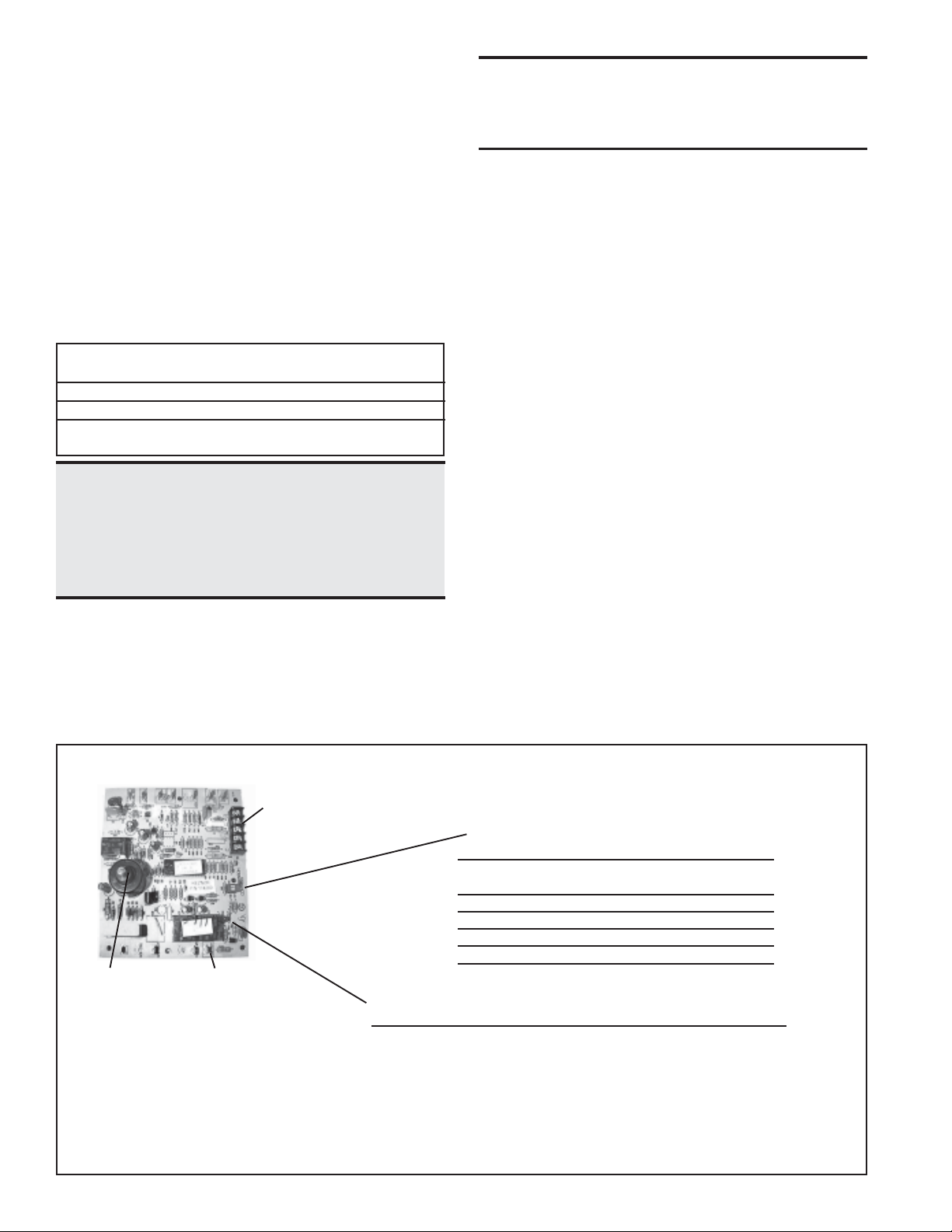
and connect to the terminal board or the integrated ignition control
module. The 115 volt supply wiring connects to pigtails on the lower
portion of the terminal board. The terminal strip for 24 volt thermostat
connections is located on the upper portion of the ignition control
module. See Figure 9.
Consult the wiring diagram supplied with your heater. A typical wiring
diagram is on page 15.
CAUTION: If any of the original wire as supplied
with the appliance must be replaced, it must be
replaced with wiring material having a
temperature rating of at least 105°C, except for
limit control and sensor lead wires which must
be 150°C. See Hazard Levels, page 2.
12. Thermostat and Connections
A thermostat is not standard equipment but is an installation requirement. Use either an optional thermostat available with the heater or a
field-supplied 24-volt thermostat. Install according to the thermostat
manufacturer's instructions.
Make sure that the heat anticipator setting on the thermostat is in accordance with the amperage value noted on the wiring diagram of your
heater.
13. Fan Motor
The fan motor is equipped with thermal overload protection of the automatic reset type. Should the motor refuse to run, it may be because of
improper current characteristics. Make certain that the correct voltage
is available at the motor.
Form RZ -NA-I-SFT, Mfg No. 173474 (Rev 6), Page 13
Page 15
14. Combustion Air Proving
Switch
The combustion air proving switch is a pressure sensitive switch that
monitors air pressure to ensure that proper combustion air flow is available. The switch is single pole/double throw with the normally open
contacts closing when a decreasing pressure is sensed in the system.
On start-up when the heater is cold, the sensing pressure is at the most
negative level, and as the heater and flue system warm up, the sensing
pressure becomes less negative. After the system has reached equilibrium (about 20 minutes), the sensing pressure levels off.
If a restriction or excessive flue length or turns cause the sensing pressure to be outside the switch setpoint, the pressure switch will function
to shut off the main burners. The main burners will remain off until the
system has cooled and/or the flue system resistance is reduced. The
Table below lists the approximate water column negative pressure readings and switch setpoints for sea level operating conditions.
Model Start-Up Equilibrium Set Point Set Point
Sizes Cold “OFF” “ON”
45, 60, 75 -1.20 -0.75 -0.60 -0.70
100, 125 -1.10 -0.70 -0.40 -0.50
150, 200 -1.50 -0.90 -0.65 -0.75
250, 300
DANGER: Safe operation of this unit requires
proper venting flow . NEVER bypass combustion
air proving switch or attempt to operate the unit
without the venter running and the proper flow
in the vent system. Hazardous conditions could
result. See Hazard Levels, page 2.
WARNING: The operating valve is the prime safety
shutoff. All gas supply lines must be free of dirt or
scale before connecting the unit to ensure positive
closure. See Hazard Levels, page 2.
16. Ignition System
This heater is equipped with a direct spark integrated control system.
The system monitors the safety devices and controls the operation of
the fan and venter motors and the gas valve between heat cycles.
Ignition System Operating Sequence -- On a call for heat from the
thermostat, the system energizes the venter motor and goes through a
10-second prepurge. The system verifies that the pressure switch has
changed states closing the normally open contactor and that the high
limit is in the closed state. The gas valve is then energized and the
ignition system provides the high voltage spark to the electrode to ignite the main burner gas. Burner flame is electronically sensed by the
control upon carryover of all burners. (A separate solid metal probe is
used as the flame sensing function. A low voltage electrical signal is
imposed on the metal probe which is electrically isolated from ground.
When the flame impinges on the flame sensing probe, the flame acts as
a conduction path to ground. The flame rectifies and completes the DC
circuit, and the ignition system acknowledges the flame.) The fan motor is energized by the system after 30 seconds of flame sensing.
After the thermostat has been satisfied, the system de-energizes the gas
valve, the venter motor goes through a 45-second post-purge, and the
fan motor remains energized for an additional 120 seconds.
NOTE: This is a three trial system, should the unit not sense burner
flame, the unit will lockout for one hour before initiating another trial
for ignition. To initiate another trial for ignition before the one hour,
requires that either the thermostat be reset or the power to the unit be
interrupted for 30 seconds.
15. Gas Valve
The main operating gas valve is powered by the 24-volt control circuit
through the thermostat and safety controls. The main control valve is
of the diaphragm type providing regulated gas flow preset at the factory.
24-volt T erminal S trip
for Thermostat
Connections
Ignitor
Connection
Line Voltage
Connection
Ignition Control Module LED Codes
Slow Flash ..... Normal Operation, No call for heat
Fast Flash ...... Normal Operation, Call for heat
2 Flashes ......... System Lockout, Failed to detect or sustain flame
3 Flashes ......... Pressure Switch Open or Closed
4 Flashes ......... High Limit or Flame Rollout Switch Open
5 Flashes ......... Flame Sensed and Gas Valve not energized
Steady On ....... Internal Failure - Replace the ignition control module
17. Burners
This unit heater has inshot burners designed to provide controlled flame
stability without lifting or flashback with either natural or propane gas.
The burners are lightweight and factory mounted in an assembly which
permits them to be removed as a unit for inspection or service.
Figure 9 - Electrical Connections on the Integrated
Ignition Control Module in the Control Compartment
Fan Delay to OFF Switch (DIP Switch Settings)
(selected prior to call for heat)
SW1 Fan Delay
1 2 To OFF (seconds)
OFF OFF 90
OFF ON 120 (Factory Preset)
ON OFF 180
ON ON 240
Form RZ -NA-I-SFT, Page 14
Page 16
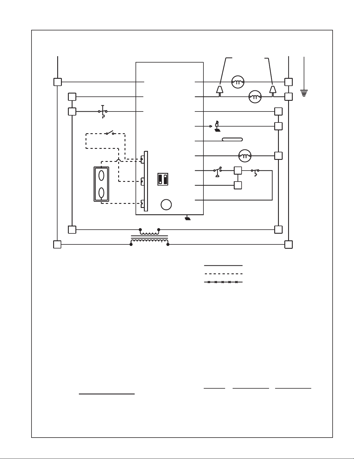
Typical Wiring Diagram
L1
(HOT)
L2
115/1/60
(COM)
(SEE NOTE 6)
BK
DSI CONTROL
BK
L1
BL
1
1
FLAME
ROLLOUT SWITCH
BL
BK
BL
BL
LINE
VAC HOT
24VAC
HOT
ROLLOUT
IN
BLWR AUX
ACB HEAT
GROUND
CMB
BK
BK
BR
MODELS 45-75 ONLY
HV LEAD
OPTIONAL SP-ST
S/W SWITCH
R
FLAME SENSE
VALV E
PRESSURE SWITCH
SW1
BL
G
W
24V
115 VOLT
LED
R
W
THERMOSTAT
OPT. SINGLE STAGE
SET ANT. AT 0.6 AMPS
1
L1
BK
PSW
HI LIMIT
IN
HI LIMIT
OUT
BR
30 VA. CONTROL
W
TRANSFORMER
Y
CHASSIS GRND.
IGNITOR
R
NC
CNO
Y
R
VENTER MOTOR
BK
FAN MOTOR
BK
BURNER GROUND
FLAME SENSING
MAIN VALVE
BL
R
Y
2
2
BR
HIGH
LIMIT
BK
BR
PROBE
BR
R
W
G
GRD
BK
BK
L2
L2
G
G
G
G
L2
1. SET THERMOSTAT AT LOWEST SETTING.
2. TURN ON MANUAL GAS VALVE.
3. TURN ON POWER TO UNIT.
4. SET THERMOSTAT AT DESIRED SETTING.
5. THERMOSTAT CALLS FOR HEAT, ENERGIZING THE VENTER MOTOR.
6. VENTER PRESSURE SWITCH CLOSES, FIRING UNIT.
7. BURNER FLAME IS SENSED, AND IN 30 SECONDS THE FAN
MOTOR IS ENERGIZED.
8. IF THE FLAME IS EXTINGUISHED DURING MAIN BURNER OPERATION,
THE INTEGRATED CONTROL SYSTEM CLOSES THE MAIN VALVE AND
MUST BE RESET BY INTERRUPTING POWER TO THE CONTROL CIRCUIT
(SEE LIGHTING INSTRUCTIONS).
1. THE FOLLOWING CONTROLS ARE FIELD INSTALLED OPTIONS: THERMOSTAT
THERMOSTAT AND S/W SWITCH
2. DOTTED WIRING INSTALLED BY OTHERS.
3. CAUTION: IF ANY OF THE ORIGINAL WIRING AS SUPPLIED WITH THE
APPLIANCE MUST BE REPLACED, IT MUST BE REPLACED WITH WIRING MATERIAL
HAVING A TEMPERATURE RATING OF AT LEAST 105 C. EXCEPT FOR SENSOR
LEAD WIRE AND LIMIT WIRING WHICH MUST BE 150 C.
4. USE 18 GA. WIRE FOR ALL WIRING ON THE UNIT.
5. LINE AND FAN MOTOR BRANCH WIRE SIZES SHOULD BE OF A SIZE TO PREVENT
VOLTAGE DROPS BEYOND 5% OF SUPPLY LINE VOLTAGE.
6. THESE WIRE NUTS ARE NOT USED ON ALL MODELS.
SLOW FLASH NORMAL OPERATION - NO CALL FOR HEAT
FAST FLASH NORMAL OPERATION - CALL FOR HEAT
2 FLASHES SYSTEM LOCKOUT - FAILED TO DETECT OR SUSTAIN FLAME
3 FLASHES PRESSURE SWITCH OPEN OR CLOSED
4 FLASHES OPEN CIRCUIT TO HIGH LIMIT OR FLAME ROLLOUT TERMINAL
5 FLASHES FLAME SENSED AND GAS VALVE NOT ENERGIZED
STEADY ON INTERNAL FAILURE (MICRO-CONTROLLER FAILURE: SELF CHECK)
OPERATING SEQUENCE
NOTES
LED CODES
DIP SWITCH SETTINGS
SW1
1 2 FAN DELAY TO OFF
OFF OFF 90 SECONDS
OFF ON 120 SECONDS (FACTORY SETTING)
ON OFF 180 SECONDS
ON ON 240 SECONDS
WIRING CODE
BLACK - BK
BROWN - BR
RED - R
ORANGE - O
YELLOW - Y
GREEN - G
BLUE - BL
PURPLE - PR
WHITE - W
TOTAL WIRE
LENGTH
150'
250'
350'
FACTORY WIRING
FIELD WIRING
OPTIONAL FACTORY WIRING
FIELD CONTROL WIRING
DISTANCE FROM
UNIT TO CONTROL
75'
125'
175'
Figure 10 - Wiring Diagram
MIN. RECOMMENDED
WIRE SIZE
#18 GA. WIRE
#16 GA. WIRE
#14 GA. WIRE
No. 155142 Revision 3
Form RZ -NA-I-SFT, Mfg No. 173474 (Rev 6), Page 15
Page 17
CHECK/TEST/START-UP
18. Check Installation and Start-Up
Check the installation prior to start-up:
Check suspension. Unit must be secure and level.
Check clearances from combustibles. Requirements are
shown in Paragraph 6.
Check vent/combustion air system to be sure that it is in-
stalled according to the instructions in Paragraph 9.
Check piping for leaks and proper gas line pressure. Bleed
gas lines of trapped air. See Paragraph 10.
Check electrical wiring. Be sure all wire gauges are as rec-
ommended. A service disconnect switch should be used.
V erify that fusing or circuit breakers are adequate for the load
use.
Start-Up
Operating Instructions and Operating
Sequence
WARNINGS: For your safety, read before
operating. If you do not follow these instructions
exactly, a fire or explosion may result causing
property damage, personal injury , or loss of life.
• This appliance does not have a pilot. It is
equipped with an ignition device which automatically lights the burner. Do not try to light the
burner by hand.
Instructions
1. Set thermostat at lowest setting.
2. Turn off all electric power to the appliance.
3. This appliance is equipped with an ignition device which au-
tomatically lights the burner. Do not try to light the burner by
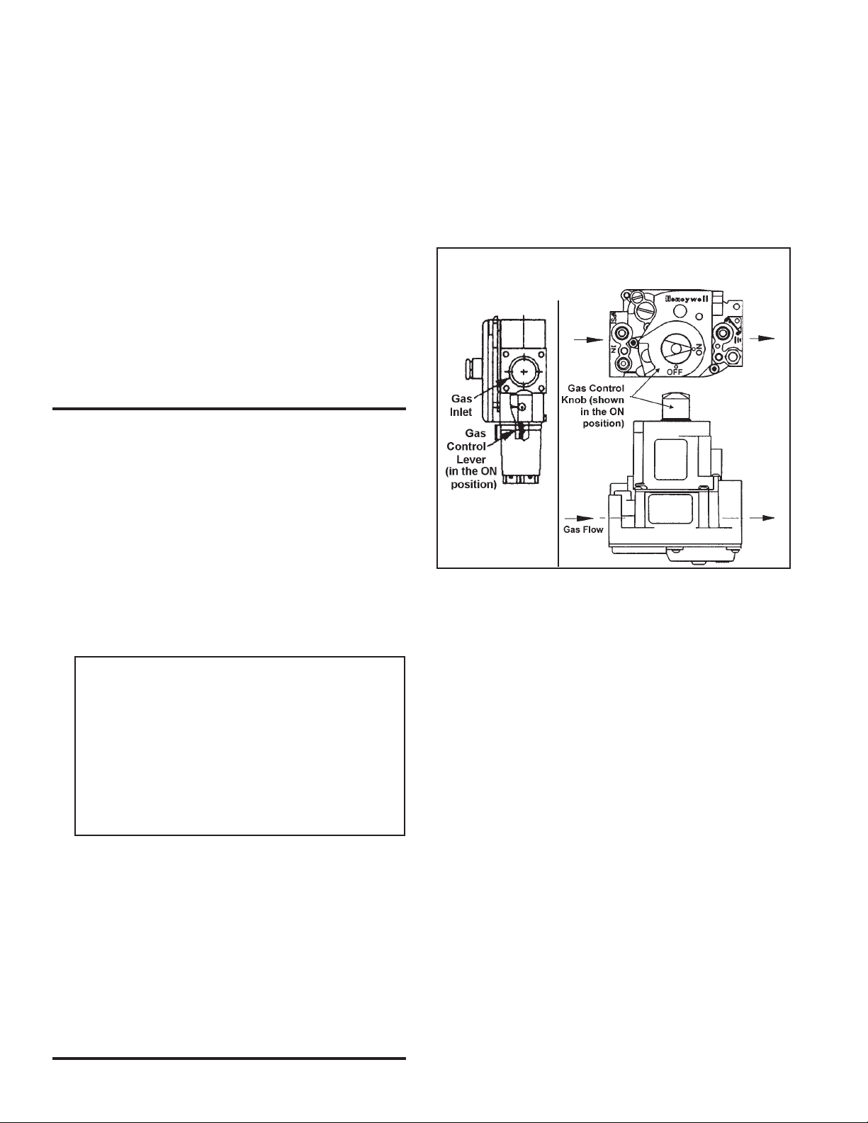
hand. Open the access door and locate the gas control (ON/
OFF) knob or lever on the gas valve.
Figure 11 - Gas Valve (Depending on the size and date
of manufacture, the heater could have either of these
types of valves.)
• Before operating, smell all around the appliance
area for gas. Be sure to smell next to the floor
because some gas is heavier than air and will settle
on the floor.
WHAT TO DO IF YOU SMELL GAS
• Do not try to light any appliance.
• Do not touch any electrical switch; do not
use any phone in your building.
• Immediately call your gas supplier from a
neighbor's phone. Follow the gas supplier's
instructions.
• If you cannot reach your gas supplier, call
your fire department.
• Use only your hand to turn the gas control ON/
OFF knob or lever on the gas valve. Never use
tools. If the valve ON/OFF knob or lever will not
turn by hand, do not try to repair it. Call a qualified service technician. Force or attempted repair may result in a fire or explosion.
• Do not use this appliance if any part has been
under water . Immediately call a qualified service
technician to inspect the appliance and to replace
any part of the control system and any gas control which has been under water.
4. Turn the gas control knob or lever clockwise to "OFF".
5. Wait five (5) minutes to clear out any gas. Then smell for gas,
including near the floor . If you smell gas, STOP! and follow
the steps in the WARNINGS printed above or on the Operat-
ing Label on the heater. If you do not smell gas, proceed to
the next step.
6. Turn the gas control knob or lever counterclockwise to "ON".
7. Close the access door.
8. Turn on the electric power to the heater.
9. Set the thermostat to the desired setting.
NOTE: If the appliance does not operate, follow the instruc-
tions "T o T urn Off Gas to Appliance" printed below (and on the
Operating Label on the heater) and call your service technician.
10. Thermostat calls for heat, energizing the venter motor.
11. V enter pressure switch closes, firing the unit.
12. Burner flame is sensed and in 30 seconds, the fan motor is
energized.
13. If the flame is extinguished during the main burner opera-
tion, the integrated control system closes the main valve and
must be reset by interrupting power to the control circuit.
(See lighting instructions on the heater .).
Form RZ -NA-I-SFT, Page 16
Page 18
TO TURN OFF GAS TO THE APPLIANCE
1) Set thermostat to lowest setting
2) If service is to be performed, turn off all electric power to the
appliance.
3) Open the access door.
4) Turn the gas control knob or lever clockwise to "OFF". Do
not force.
5) Close the access door.
Check installation after start-up:
If the heater is being derated for high altitude operation (See Para-
graph 5), follow the instructions in Paragraph 10 to adjust the manifold pressure. Be sure to complete the "change pressure" tag and
adhere it on the heater close to the gas valve.
If unit is not being derated, measure to verify manifold gas pres-
sure. Follow instructions in Paragraph 10.
Turn the unit off and on, pausing two minutes between each cycle.
Observe for smooth ignition.
Place the "Owner's Envelope" containing the Limited W arranty , this
booklet, and any control or optional information in an accessible
location near the heater. Follow the instructions on the envelope.
DANGER: The gas burner in this gas-fired equipment is designed and equipped to provide safe and
economically controlled complete combustion. However , if the installation does not permit the burner
to receive the proper supply of combustion air, complete combustion may not occur. The result is
incomplete combustion which produces carbon monoxide, a poisonous gas that can cause death. Safe
operation of separated-combustion, indirect-fired gas burning equipment requires a sealed, properly
operating vent system which vents all flue products to the outside atmosphere. F AILURE TO PROVIDE
PROPER VENTING WILL RESULT IN A HEALTH HAZARD WHICH COULD CAUSE SERIOUS
PERSONAL INJURY OR DEATH.
Install either the horizontal or vertical combustion air/vent system illustrated in Paragraph 9 using the
concentric adapter supplied. Always comply with the combustion air requirements in the installation
codes and instructions. Combustion air at the burner should be regulated only by manufacturer-provided
equipment. NEVER RESTRICT OR OTHERWISE ALTER THE SUPPLY OF COMBUSTION AIR
TO ANY HEATER. CHECK THE COMBUSTION AIR/VENT SYSTEM FOR SOUNDNESS AND
FUNCTION; MAINTAIN IT IN PROPER OPERATING CONDITION.
Form RZ -NA-I-SFT, Mfg No. 173474 (Rev 6), Page 17
Page 19
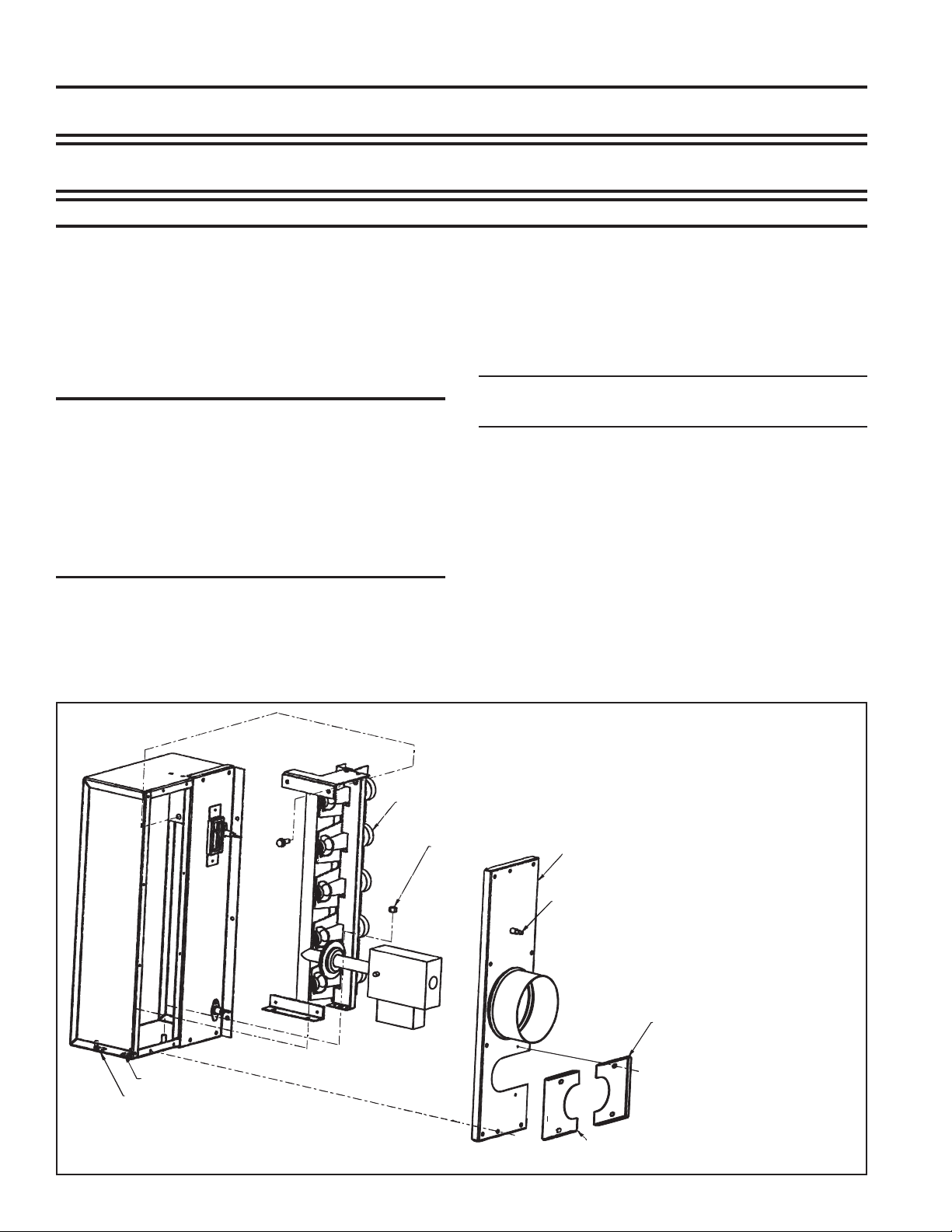
SERVICE AND MAINTENANCE
WARNING: Should overheating occur , or the gas supply fail to shut off, shut off the manual gas valve
to the appliance before shutting off the electrical supply.
WARNING: Do not use this appliance if any part has been under water. Immediately call a qualified
service technician to inspect the appliance and replace any gas control which has been under water.
WARNING: If you turn off the power supply, turn off the gas. See Hazard Levels, page 2.
This unit will operate with a minimum of maintenance. T o ensure long
life and satisfactory performance, a heater that is operated under normal conditions should be inspected and cleaned at the start of each
heating season. If the heater is operating in an area where an unusual
amount of dust or soot or other impurities are present in the air, more
frequent maintenance is recommended.
When any service is completed, be careful to reassemble correctly to
ensure that no unsafe conditions are created. When re-lighting, always
follow the lighting instructions on the heater.
W ARNING: Excessive dirt buildup on and inside
the burner ports could cause fuel gas to spill out
of the back of the burner tube causing gas odor
inside the building. If uncorrected, fuel spilling
out of the back of the burner tube could cause a
fire or explosion. To prevent fuel gas from spilling
from the back of the burners, check the burner
ports at least annually and clean if necessary.
Maintenance Schedule
The following procedures should be carried out at least annually (See
Paragraphs 19-28.):
• Clean the fan blade, fan guard, and motor.
• Clean the heat exchanger both internally and externally.
• Check the burners for scale, dust, or lint accumulation.
• Check the vent/combustion air system for soundness.
Clean the screen in the vent terminal cap. Replace any
parts that do not appear sound.
• Check the wiring for any damaged wire. Replace
damaged wiring. (See Paragraph 1 1 for replacement
wiring requirements.)
NOTE: Use only factory-authorized
replacement parts.
19. Burner Removal
Instructions for Burner Removal (See Figure 12)
1. Shut the gas supply off ahead of the combination valve.
2. Turn off electric supply.
3. Open the access panel..
4. Disconnect the union on the outside of the unit and remove the gas
pipe from the inlet of the gas valve.
5. On the burner box end of the flexible hose, loosen the hose clamp.
Slide the hose off the collar.
6. Disconnect the silicone tubing from the static tap on the burner box
cover.
Figure 12 - Removing the burner/rack manifold assembly
(For clarity, the heater cabinet and other parts are not
illustrated; do not remove the burner box assembly fr om
the heater .)
Locating
Pins (hidden)
Burner
Box Assembly
Form RZ -NA-I-SFT, Page 18
Lift up and pull out on the burner
rack and manifold assembly
1/4-20 Hex Nut
Burner Box Cover
Static Pressure Tap
Manifold
Seal Plate
Manifold
Cover
Plate
Page 20
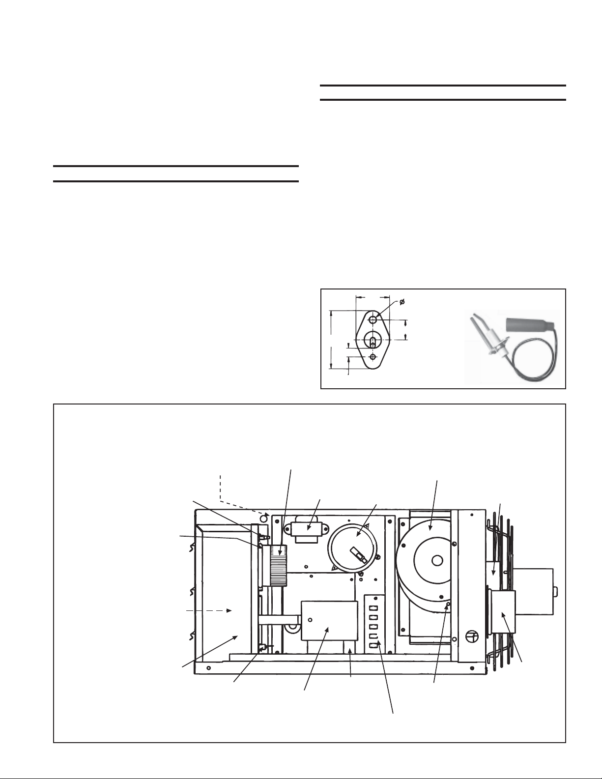
7. Remove the small manifold seal plate and cover plate. Remove the
burner box cover. The burner rack assembly is visible.
8. At the bottom of the burner rack assembly, remove the nut that
secures the burner rack to the bolt welded to the burner box bottom.
At the top of the burner rack assembly, remove the bolt that attaches the burner rack assembly to the bracket. Lift the burner rack/
manifold assembly upward (to clear the locating weldpins) and pull
the assembly out of the heater.
Clean the Burners (requires a wire brush,
cleaning cloth, and an automotive type aerosol
degreaser or refrigerant coil cleaner)
CAUTION: Use of eye protection is recommended.
Excessive dirt buildup on and inside the ports on the burner could
cause fuel gas to spill out of the back of the burner tube. Fuel gas
spilling out of the back of the burner tube will cause gas odor inside
the building, and if not corrected, could eventually cause a fire/explosion hazard. T o prevent fuel gas spilling from the back of the burners,
check the burner ports at least annually and clean if necessary . Remove
any soot deposits from the burner with a wire brush. Clean the ports
with an aerosol degreaser and/or compressed air. W ipe the inside of the
burner tube clean. (Cleaning the burner with an aerosol degreaser is
highly recommended as the degreaser will retard future buildup of dirt.)
Inspect the cleaned burner for any damage or deterioration. If the burner
has any damage or signs of deterioration, replace it.
Re-assemble the heater and test for proper operation.
20. Burner Orifices
Heaters are shipped with orifices of proper size and type for gas and
altitude specified on the order. When ordering replacement orifices,
give BTUH content, specific gravity of gas, and altitude, as well as the
model and serial number of the heater.
21. Heat Exchanger
The outside of the tubular heat exchanger can be cleaned from the
front of the heater with an air hose and/or a brush. Remove all accumulated dust and grease deposits.
CAUTION: Eye protection is recommended.
The inner surfaces of the heat exchanger can be reached for cleaning
with the burner, turbulators and venter assembly removed (See Paragraph 18 and Figures 13 and 14). Turbulators are "wavy" strips of metal
that extend into the heat exchanger tubes. Remove and clean the
turbulators (save the screws). Clean the inside of the tubes with a long
furnace brush or a heavy wire to which steel wool has been attached.
Brush inside each heat exchanger tube until all foreign material is removed. A flashlight is helpful in examining the inside of the tubes.
Slide the clean turbulator strips back into the tubes and re-attach using
the screws removed.
22. Ignition System
To access the ignition system, follow Steps 1-3 in Paragraph 19.
Ignitor - Refer to Figure 14 and locate the ignitor (on the side of the
burner rack). Disconnect the wire; remove the screw and the ignitor.
Clean the ignitor assembly with an emery cloth.
Spark gap must be maintained to 1/8". See Figure 13.
.74
1.275
.125 ±.015 Spark Gap
5/32
7/16
Spark Gap
Measurement
Figure 13 - Ignitor Assembly
Limit Control - Sizes
100-300 (located in heat
exchanger compartment)
Flame Sensor
Flame Rollout
Switch - Sizes 45-75
(located on the burner
box cover behind
the collar; disconnect
hose to access)
Limit Control Location -
Sizes 45-75 (located in heat
exchanger compartment;
remove louvers to access)
Burner/Manifold
Assembly
Figure 14 - Location of Controls on a Model SFT45-300 (with the door open, all of the
controls except the limit control are visible in one compartment)
Combustion Air Collar
(flex hose removed for clarity)
Venter Motor and
Wheel Assembly
Transformer
Ignitor
Gas Valve (When lighting,
turn gas control knob or lever
OFF; wait five minutes; turn
gas control knob or lever ON)
Ignition
Control
Module
Pressure
Switch
Flow Sensor (for
tubing connection
to the pressure switch)
Terminal
Block
Form RZ -NA-I-SFT, Mfg No. 173474 (Rev 6), Page 19
Venter Outlet
(Flue) Collar
Fan
Motor
Inlet
Collar
Page 21
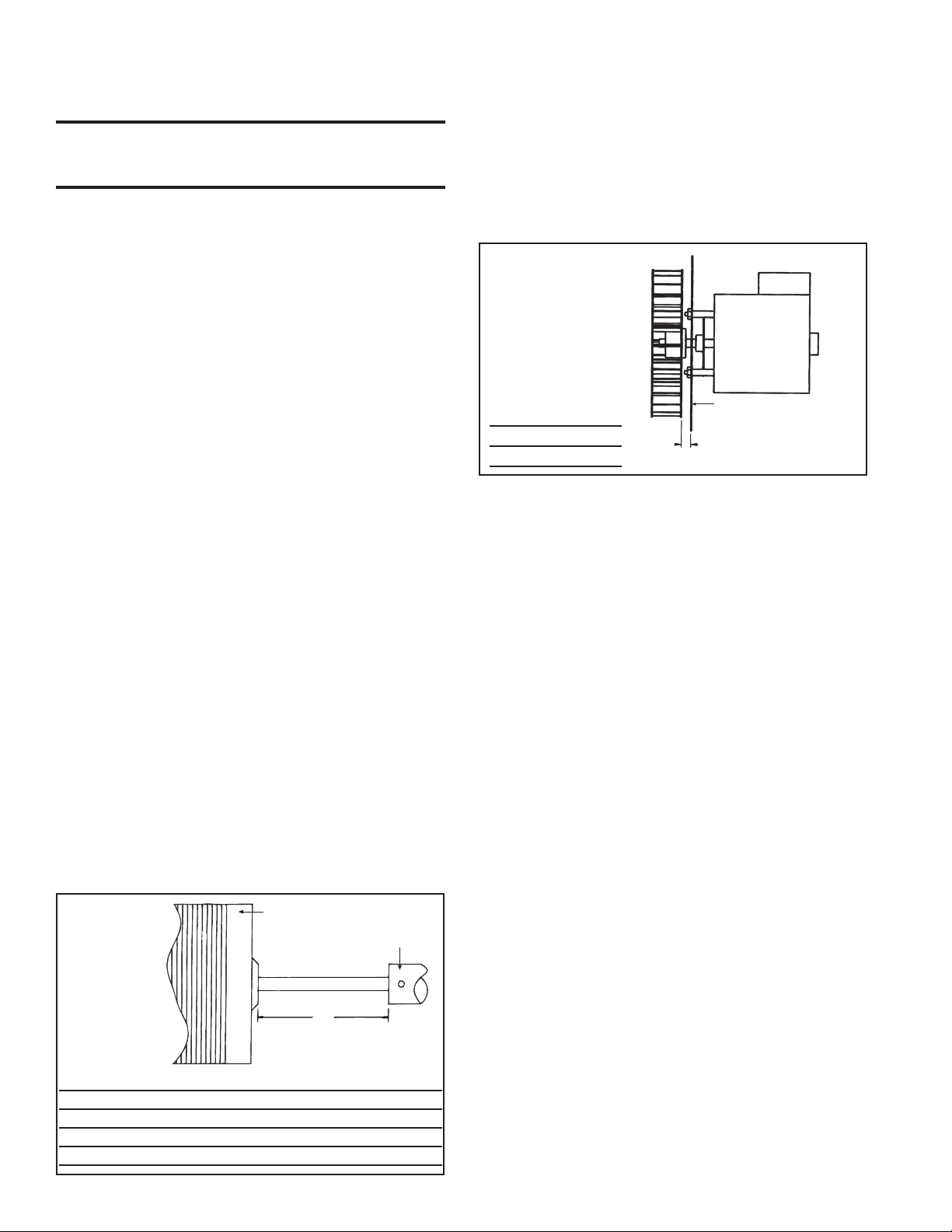
22. Ignition System (cont'd)
IMPORTANT: When re-assembling, the brown ground wire must remain attached to the ignitor.
CAUTION: Due to high voltage on the spark wire
and electrode, do not touch when energized. See
Hazard Levels, page 2.
Flame Sensor - Refer to Figure 13 and locate the flame sensor. Dis-
connect the wire; remove the screw and the flame sensor. Clean with
an emery cloth.
Ignition Control - The integrated ignition control module monitors
the operation of the heater including ignition. Do not attempt to disassemble the ignition control module. However, each heating season the
lead wires should be checked for insulation deterioration and good
connections.
Proper operation of the direct spark ignition system requir es a minimum flame signal of 1.0 microamps as measured by a
microampmeter.
For further information and check out procedure on the direct spark
ignition system, refer to the manufacturer's control operating instructions supplied with the heater.
23. Fan
Remove dirt and grease from the motor. Remove dirt and grease from
the fan guard and blades. Use care when cleaning the fan blades to
prevent causing misalignment or imbalance. Check that the hub of the
fan blades is secure to the shaft.
Follow these instructions for replacement of the fan guard, fan motor
and/or fan blades.
1. If the heater is installed, turn off the gas and disconnect the electric
power.
2. Open the hinged access door and disconnect the fan motor wires.
3. Remove the assembled parts (the fan guard, the motor and the fan
blade).
4. Disassemble and replace whatever parts are needed and reassemble
using whatever part(s) are being replaced and the original parts.
Be sure the fan blade is in the proper position on the shaft; refer to
the illustration and table in Figure 15.
Position the assembly on the heater. Attach the fan guard.
Rotate the fan blade to check for adequate clearance. If adjustment
is required, loosen the mounting screws, re-position the fan guard,
and tighten the screws. Rotate the fan blade and re-check for adequate clearance. Repeat this procedure until the assembly is positioned properly.
5. Reconnect the fan motor wires and close the access panel.
6. Restore power to the heater and turn on the gas. Light, following
the instructions on the lighting instruction plate. Check for proper
operation.
Figure 15 Proper
Position of
the Fan
Blade on the
Motor Shaft
Model Size Set Screw Torque (In-Lbs) “A” Hub to Motor
45 80 ± 10 1-1/8"
60, 75, 100, 125 120 ± 10 2"
150, 200 150 ± 10 2"
250, 300 150 ± 10 3-1/4"
Form RZ -NA-I-SFT, Page 20
Fan Motor
Fan Hub
A
24. Venter Motor
Remove dirt and grease from the motor housing. Power venter motor
is permanently lubricated.
The integrated ignition control module controls and monitors operation of the venter motor. If the contacts fail to close, the venter motor
will not run. If the contacts fail to open, the venter motor will not shut
off, preventing the combustion air pressure switch from opening.
Follow these instructions for replacement of the venter motor (Refer to
Figure 16). Keep all hardware removed to be used in re-assembling
and installing the replacement parts.
Figure 16 - Proper
spacing between
the venter wheel
and the motor
mounting plate
Venter
Wheel
Sizes A
45-125 5/16"
150-300 23/32"
1. If the heater is installed, turn off the gas and disconnect the electric
power.
2. Open the access panel. At the burner end, loosen the clamp on the
combustion air flex hose. Let the hose "hang down" so that it is out
of the way of the venter motor.
3. Disconnect the three venter motor wires at their terminal block con-
nections.
4. Holding the motor, remove the screws (3 or 4) that attach the venter
motor mounting plate to the venter housing. Remove the motor and
wheel assembly from the heater.
5. Disassemble the motor and wheel assembly:
(a) With a hex head allen wrench, loosen the venter wheel set screw .
Slide the venter wheel off the shaft.
(b) Remove the four nuts holding the motor mounting plate. Re-
move the mounting plate.
(c) Slid over each bolt is a cylindrical spacer; remove the four spac-
ers.
(d) Loosen the set screw and remove the small fan blade.
6. Re-assemble with the replacement venter motor (NOTE: Check the
gasket on the motor mounting plate; if the gasket is deteriorated or
torn, replace it - Size 45, P/N 155651; Sizes 60-300, P/N 155652):
(a) With the blade side closest to the motor, slide the small fan
blade on to the shaft. Position the blade so that it does not hit
the motor and tighten the set screw to the flat side of the motor
shaft.
(b) Slide the spacers over the bolts. Position the mounting plate
with the side with the gasket away from the motor; secure with
the nuts (hand tighten with a nut driver; do not use a power
tool). Rotate the fan to check for clearance. If required, loosen
the set screw and adjust the position of the fan blade.
(c) With the "closed" side toward the motor, slide the venter wheel
over the end of the shaft. Position the wheel with the spacing
shown in Figure 16. Tighten the set screw to the flat side of the
motor shaft.
7. Install the assembled venter motor and wheel. Follow the wiring
diagram to connect the venter wires. Re-attach the flex hose and
close the access panel.
8. Restore power to the heater and turn on the gas. Light, following
the instructions on the lighting instruction plate. Check for proper
operation.
A
Venter
Motor
Mounting Plate
(Replace mounting
plate gasket if it is
deteriorated or torn.)
Page 22
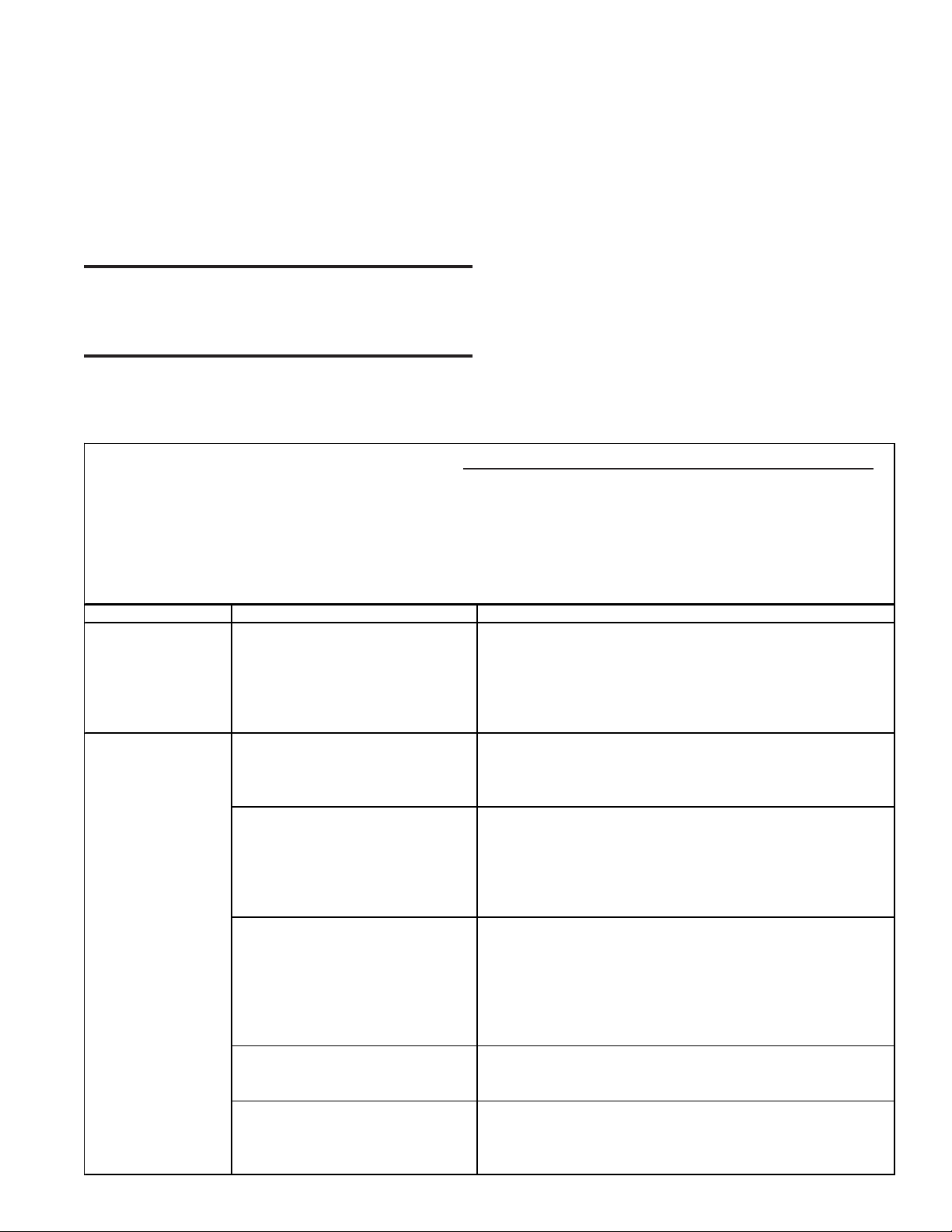
25. Limit Controls
If it is determined that a limit control needs replacing, use only the
factory-authorized replacement part that is designed for the size of heater.
T o access the limit control on Sizes 45-75, remove the louver assembly
from the front of the heater. On Sizes 100-300, the limit control is
accessible in the control compartment.
For approximate limit locations, see Figure 14 on page 19.
26. Gas Valve
The gas valve requires no field maintenance except careful removal of
external dirt accumulation and checking of wiring connections. Instructions for testing pressure settings are in Paragraph 10.
WARNING: The operating valve is the primary
safety shutoff. All gas supply lines must be free of
dirt or scale before connecting to the unit to ensur e
positive closure. See Hazard Levels, page 2.
30. Troubleshooting
27. Combustion Air Pressure
Switch
If it is determined that the pressure switch needs replacing, use only
the factory-authorized replacement part that is designed for this heater.
28. V ent/Combustion Air System
Check at least once a year. Inspection should include all joints, seams,
and the terminal caps. Clean the screen in the vent terminal cap.
Replace any defective parts.
29. Flame Rollout Switch (Applies
to Models SFT 45-75 only)
If it is determined that the flame rollout switch needs replacing, use
only the factory-authorized replacement part that is designed for the
size of heater. To access the flame rollout switch, disconnect the flexible hose from the burner box (See Figure 14 on page 17).
Check the Ignition control module - The integrated ignition control module monitors the operation of the heater and
includes an LED signal that indicates normal operation and
various abnormal conditions. If the heater fails to operate
properly, check this signal to determine the cause and/or to
eliminate certain causes.
PROBLEM PRO BABLE CAUS E REMEDY
Venter mo tor 1.
will not start 2.
Burners will 1.
not light 2.
No power to unit.
No 24 volt p ow er to venter relay.
Integrated ignition control module
3.
defective.
Defective moto r.
4.
Manual valve not open.
Air in the gas line.
Gas pressure too high or too low.
3.
No Spark:
4.
a) Loose wire connect ions a) Be certain all wire connections are solid.
b) Transformer failure b) Be sure 24 volts is available.
c) Incor rect s park gap . c) Maintain spark gap at 1/8".
d) Spark cable shorted to ground. d) Replace w orn or grounded sp ark cable.
e) Spark electrode shorted to ground e) Replace if ceramic spark electrode is cracked or grounded.
f) Burners not grounded f) Make certain integrated ig nition control module is grounded to igniter.
g) Ignition control module not grounded. g) Make certain integrated ignition control module is grounded to furnace
h) Faulty integrated ignition control
module
Lockout device interrupting control
5.
circuit by above causes.
Faulty combustion air p roving switch.6. Replace combustion air proving switch.
6.
Main valve not operating.
7.
a) Defe ctive valve a) If 24 volt is mea sured at the valve connections and valve remains
b) Loose wire connections b) Check and tight en all wiring connections.
Ignition Control Module LED Codes
Slow Flash . Normal Operation, No call for heat
Fast Flash .. Normal Operation, Call for heat
2 Flashes .... System Lockout, Failed to detect or sustain flame
3 Flashes .... Pressure Switch Open or Closed
4 Flashes .... High Limit or Flame Rollout Switch Open
5 Flashes .... Flame Sensed and Gas V alve not energized
Steady On .. Internal Failure - Replace the ignition control module
T u r n on power, ch eck supply fuses or circuit breaker.
1.
Turn up thermostat; check control transformer output.
2.
Replace integra ted i gnition control module.
3.
TO REP A IR I GNI TION CO NT ROL M O DULE; IT H AS NO FI ELD
REPLACEABLE COMPO NENTS .
Replace motor.
4.
Open manual valve.
1.
Bleed gas line.
2.
Set supply pressure at 5" w.c. to 14" w.c. for natural gas and 11" w.c.
3.
to 14" w.c. for propane gas.
4.
chassis.
h) If 24 volt is available to the integrated ignition control module and all
other causes have been eliminated, replace module.
ATTEMPT TO REPAIR IGNITI ON CONTROL MODULE; IT HAS
NO F I ELD REPLACEABLE COMPONENTS .
Reset lockout by interrupting control a t the thermostat or main
5.
power.
7.
closed, replace valve.
DO N OT ATTEMPT
DO NOT
Form RZ -NA-I-SFT, Mfg No. 173474 (Rev 6), Page 21
Page 23
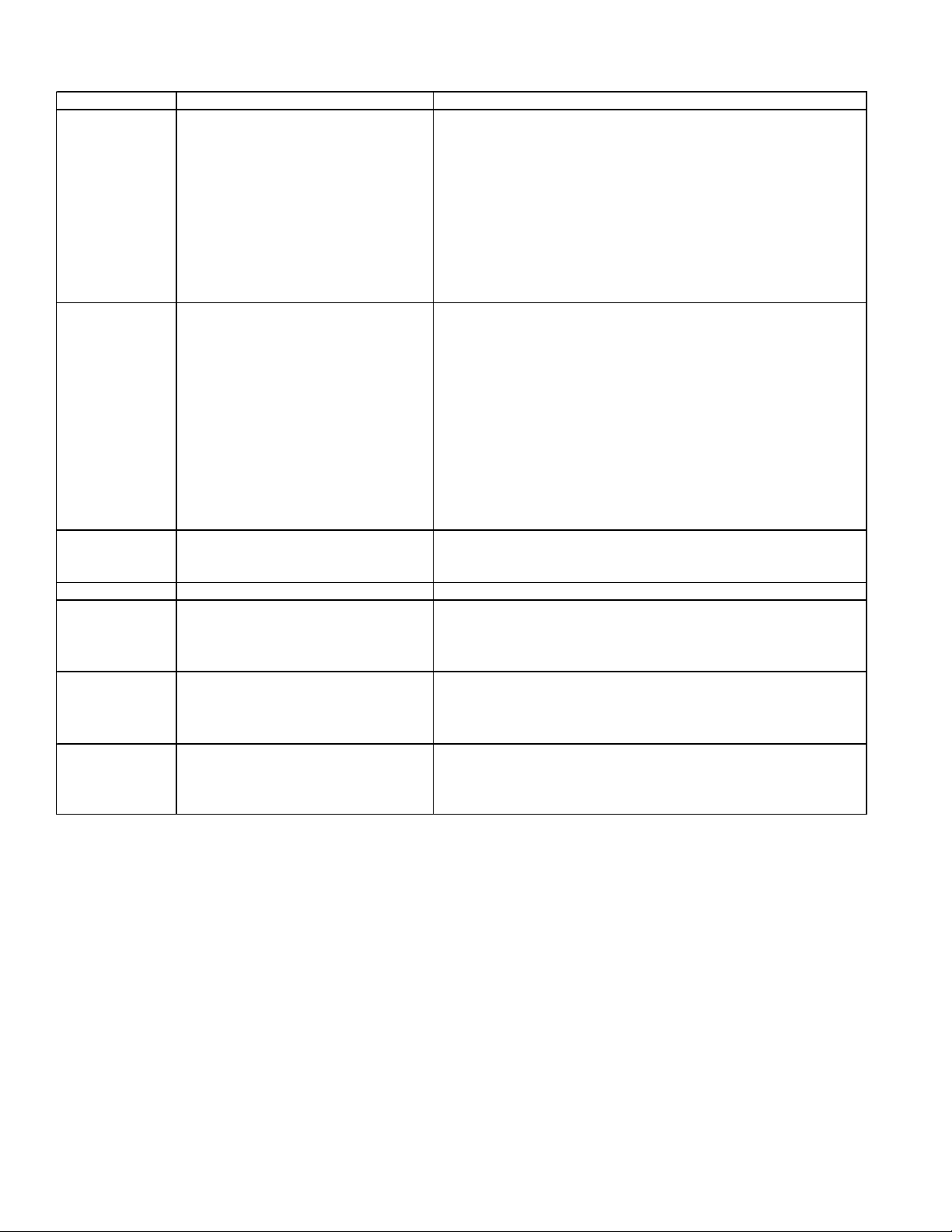
30. Troubleshooting (cont'd)
PR OBLEM (c ont' d) P ROBABLE CAUSE (cont'd) REME DY (c o nt'd)
Burne rs will n ot
li ght (cont'd)
Burne rs cycle on
and off
No heat (Heate r 1. Incorrect manifold pressure or orifices. 1. Check manifold pressure (See Paragraph 9).
Operating) 2. Cycling on limit control. 2. Check air throughput.
Cold air del ivered 1. Incorrect manifold pressure. 1. Check manifold pressure (See Paragraph 9).
Fan motor will not 1. Circuit op en. 1. Check wir ing and connections..
run 2. Defective integrated ignition contro l m o dule. 2. Replace module. DO NO T ATTEMPT TO REPAIR IGNITION
Fan motor turns on
and off while
burner is operating
(See below)
Fan mot or cuts 1. Low or high voltage supply . 1. Correct electric supply.
out on overload 2. Defectiv e motor. 2. Replace motor.
8. Integrated ignition control module does no t
power main valve.
a) Loose wire connections a) Check and tighten all wiring connections.
b) Flame sensor grounded b) Be certain flame sensor lead is not grounded or insulation or ceramic is not
c) Incorrect gas pressure c) Set supply pressure at 5" w.c. t o 14" w.c. for natural gas and 11" w.c. to 14 "
d) Cracked ceramic at sensor d) Replace sensor.
9. Flame rollout switch open
a) Air blockage through the unit a) Check for heat exchanger or vent pipe blockage.
b) Faulty flame rollout switch b) Replace flame roll out switch.
1. G as pressure too high or too low. 1. Set supply pressure at 5" w.c. to 14" w.c. for natural gas and 11" w.c. to 14"
2. Burners not grounded 2. Make certain integrated ignition control module is grounded to igniter.
3. Ignition control module not grounded. 3. Make certain integrated ignition control module is grounded to furnace chassis.
4. Faulty integrated ignition control mo dule 4. If 24 volt is available to the integrated ignition control module and all other
5. Faulty combustion air proving switch. 5. Replace combustion air proving switch.
6. Flame sensor grounded 6. Be certain flame sensor lead is not grounded or insulation or ceramic is not
7. Cracked ceramic at sensor 7. Replace sensor
8. Incorrec t pola ri ty. 8. Reverse 115V line connections at ignition control module.
3. Impr op er thermostat location or adjustment. 3. See thermostat manufacturer's instructions.
3. Def ective motor. 3. Replace motor.
1. Motor o verload dev ice cycling on and off.
3. Poor air flow. 3. Clean motor, fan and fan guard.
4. Defective bearing. 4. Replace motor.
8.
cracked. R eplace as required.
w.c. for propane gas.
w.c. for propane gas.
causes have been eliminated, replace module. DO NOT ATTEMPT TO
REPAIR IGNITION CONTROL MODULE; IT HAS NO FIELD
REPLACEABLE COMPONENTS.
cracked. R eplace as required.
CONTROL MO DULE; IT HA S NO FIELD REPLACEABLE
1.
a) Check motor load against mo tor rating plate. Replace motor if needed.
b) Check to be certain that an unauthorized air distribution device has not been
added.
Form RZ -NA-I-SFT, Page 22
Page 24

31. Heater Rating Plate
The heater rating plate is a quick reference for information about a heater and its installation requirements. In addition, the Serial No. on the rating plate identifies components used in manufacturing that specific heater. The serial number is coded to identify
the gas valve and ignition type that was installed on the heater at the time of manufacture. This information is required if service and/or replacement parts are required.
Follow the example below to decode the heater Serial No.
Example: Heater Serial No. AWH75T9N12345X
AWH 75 T9 N 12345 X
Month & Year Safety Pilot Code Type of Type of Consecutive Plant
of Manufacture (Type of Ignition) Valve Gas* Number Designation
* N = Natural Gas; L = Propane Gas
IMPORTANT: The serial number code can only identify the original equipment. Before installing or servicing, check for a gas conversion label.
When inquiring about replacement parts, always provide the complete Model No. and
Serial No. Each heater has a "Replacement Parts Label" attached that identifies parts
specific to that heater, as well as the Model and Serial No. of the heater.
Identification of Serial No. Valve
Codes for Valves Used on Model SFT
Heaters
Code P/N Manufacturer *Gas
T9 147133 Robertshaw #7222DER N
U1 147134 Robertshaw #7222DERLP L
U2 147830 Honeywell #VR8205M1130 N
U3 147560 Honeywell #VR8205M1148 L
U6 150839 Honeywell #VR8305M4009 N
U7 150840 Honeywell #VR8305M4017 L
W6 172552 Honeywell #VR8105M2187 N
W7 172553 Honeywell #VR8105M2825 L
Form RZ -NA-I-SFT, Mfg No. 173474 (Rev 6), Page 23
Page 25

FOR SERVICE OR REPAIR, FOLLOW THESE STEPS IN ORDER:
FIRST: Contact the Installer
Name ___________________________________________________________________________
Address ___________________________________________________________________________
___________________________________________________________________________
___________________________________________________________________________
Phone ___________________________________________________________________________
SECOND: Contact the nearest distributor (See Yellow Pages). If no listing,
contact Authorized Factory Representative, 1-800-695-1901 (Press 1).
THIRD: Contact REZNOR®/ Thomas & Betts Corporation
150 McKinley Avenue
Mercer, PA 16137
Phone: (724) 662-4400
Model No. ___________________________________________________________________________
Unit Serial No. ___________________________________________________________________________
Date of Installation ___________________________________________________________________________
Form RZ -NA-I-SFT, Page 24
(800) 695-1901 ww w.ReznorOnLine.com
©2004 Thomas & Betts Corporation, All rights reserved. Printed in the U.S.A.
MANUFACTURER OF HEATING, VENTILATING, AND COOLING SYSTEMS
Trademark Note: Reznor® is registered in the United States and other countries.
804 OG POD Form RZ-NA-I-SFT
 Loading...