

Page 1
IMPORTANT
V
1. Always include complete heater model and serial number so
that any specification change can be considered for parts shipment. It can save time and expense.
2. Specifications are subject to change without notice.
3. We reserve the right to substitute functional replacements
4. Order by Part Number. Do not order by Option Number.
NOTE: Replacement parts manual for Models RIH and TRP
has been revised to Form RZ-NA-P-VR/TRP/RIH
INFRARED
HEATERS
Replacement Parts Form RZ-NA-P-TR
Obsoletes Form 709 (Version B)
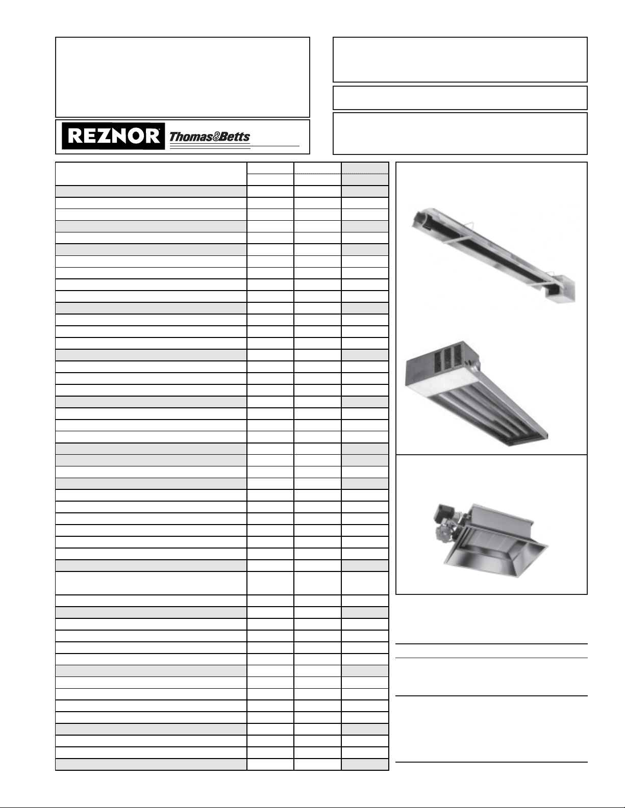
APPLIES TO: INFRA-REZTM Heater Models
TR/TR-H and TRP
and Models RIH/RIHV
INDEX by M odel TR/TR-H TRP RIH/RIH
Replacement parts on pages 4-8, 13- 14 9-14 15- 16
Burner Assembly 5 11 16
Burner/Control Box and Components 4 9 -Capacitor 5 9 -Chains for Hanging 13 11 15
Combustion Cham b er Tube 7 -- -Connector, Flexible Gas 13-14 13-14 15
Conversion Kit, Altitude 8 -- -Conversion Kit, Gas 8 12 -Cord, Power 6 11 -Door Assembly (Burner Box) 4 9 -Electric Components 6 10-11 15
Heat Exchanger/Reflector Assembly -- 11 -Heat Exchanger Tube (5-ft) (Same as Option UA1) 7 -- -Heat Exchanger Tube (10-ft) 7 -- -Ignition Controller 6 10 15
Inlet Air Kit (Combustion Air, Same as Option DE2) 13 -- -"L" Heat Exchanger Tube (Same As Option UC2) 8 -- -Light (Burner Indicator) 6 -- -Manifold 5 11 16
Motor 5 9 -Multiple Heater Control (Same as Options CL31/32) 13-14 -- -Orifice, Air (Combustion Air Restrictor Plate) 4 -- -Orifice, Gas 5 12 16
Pilot 7 -- 15
Rating Plate/Model Convers ion Label 2 & 3 2 & 3 -Reflector 7 11 16
Reflector End Cap 7 -- -Reflector Gap Cover 7-8 -- -Reflector Retainer Kit 7 -- -Relay, Time Delay 6 -- -Replacement Parts Tag 3 3 -Restrict or Plate 4 -- -Screen, Protective (Same as Option DN3) -- -- 16
Separated Combustion Combustion Air/Vent
Terminal Kits (Same as Options CC2 & CC6)
Serial No. 2 & 3 2 & 3 -Shield, Heat (Same as Option DO3) -- -- 16
Shield, Side (Same as Options CD13-20, 30-31) 13-14 13-14 -Switch, Door 6 -- -Switch, Air Pressure 6 10 -Transformer 6 10 -Thermostat/Thermostat Accessories 13 13 15
Tube Connection Hardware 7 11 -Tube Packages 7 -- -Turnbuckle 13 13 -"U " Heat Exchanger Tube (Same as Option UB3 ) 7-8 -- -Valve 6 10 15
Vent Cap 4 -Vent Kit for Dual Vent (Same as Option CC5) 13 13 -Wire Grid (Same as Option DN2) -- -- 16
-- 12 --
INFRA-REZTM Model, Low-Intensity,
Tubular, Infrared Heaters
TR/TR-H T ubular
Radiant Heaters
TRP Tubular Radiant
Packaged Heater
Models RIH/RIHV High-Intensity
Infrared Heaters
REFERENCES:
Form RGM
450, Model RIH/RIHV Installation/Maintenance
452, Model TRP Installation/Operation/Mainte-
nance
452-GC, Model TRP Gas Conversion
456, Model TR/TR-H Installation
456-OMS, Model TR/TR-H Maintenance and
Service
456-GC, Model TR Gas Conversion
456-HA, Model TR High Altitude Conversion
Form 709, page 1
Page 2
Rating Plate and Serial No.
(Example is a Model TRP)
REZNOR
MERCER, PA. USA 16137
MADE IN MEXICO / FABRIQUÉ AU MEXIQUE
TUBULAR INFRARED HEATER
FOR INDUSTRIAL / COMMERCIAL USE ONLY
POUR USAGE INDUSTRIEL / COMMERCIAL SEUL
ANSI Z83.6b- [ A ] CAN/CGA-2.16-M [ A1 ] INFRARED HEATER
MODEL/DATE MODÈLE/DATE [ B ] [ C ]
SERIAL NO. #DE SÉRIE [ ]
TYPE OF GAS TYPE DE GAZ [ E ]
VOLTS/PH/HZ VOLTS/PH/HZ [ D ]
MAX. TOTAL AMPS TOTALE MAX. DE AMPERAGE [ K ]
ALTITUDE ALTITUDE [ F ] FEET [ G ] METERS
GAS ORIFICE SIZE DIMENSION DE GAZ L’ORIFICE [ H ]DRILL/FORET
NORMAL INPUT ENTRÉE NORMALE [ I ]BTUH
ALT. ADJ. NORMAL INPUT ALT. ADJ. ENTRÉE NORMALE [ Q ]BTUH
MANIFOLD PRESSURE PRESSION DE LA TUB [ O ]IN. W.C./PO/COL D’EAU
MIN. PERMISSIBLE GAS SUPPLY PRESSURE FOR PURPOSE OF INPUT ADJUST-
MENT: [ P ] IN. W.C.
CLEARANCES TO COMBUSTIBLE CONSTRUCTION:
TOP- [ X ] INCHES; SERVICE SIDE- [ Y ] INCHES; OPPOSITE SIDE [ Z ] INCHES;
FLUE CONNECTION - 6 INCHES; BELOW- [ W ] INCHES
REFLECTOR MAX. MOUNTING ANGLE BELOW FRONT/REAR
STANDARD 0 DEGREES [ W ]” [ S ]”
STANDARD 45 DEGREES [ W ]” [ T ]”
STANDARD W/SIDE [ R ] DEGREES [ W ]” [ U ]”
SHIELDS
* 24" IF UNVENTED
THIS UNIT IS FOR USE WITH NATURAL OR PROPANE GAS. A CONVERSION KIT, AS
SUPPLIED BY THE MANUFACTURER, SHALL BE USED TO CONVERT THIS HEATER
TO THE ALTERNATE FUEL.
FOR ALTERNA TE INST ALLATIONS USE THE LATEST ADDITIONS OF THE APPROPRIATE STANDARDS LISTED BELOW:
STANDARD ON AIRCRAFT HANGARS: ANSI/NFPA 409
STANDARD ON PARKING STRUCTURES: ANSI/NFPA 88A
STANDARD ON REPAIR GARAGES: ANSI/NFPA 88B
PRES. D’ALIM MIN. ACCEPT ABLE DE GAZ POUR DES FIN DE RÉGLAGE DE L ’ENTRÉE:
[ P ] PO/COL D’EAU
DÉGAGEMENT ENTRÉE LES CONTSRUCTIONS COMBUSTIBLES:
EN HAUT- [ X ] PO; CÔTÉ ENTRETIEN [ Y ]PO; CÔTÉ OPPOSÉ [ Z ] PO;
EN BAS- [ W ] PO; RACCORD DE TUYAUX- 6 PO
CET APPAREIL POUR UTILISATION AVEC LE GAZ NATUREL OU LE PROPANE.
UNE TROUSSE DE CONVERSION FOURNIE PAR LE FABRICANT DOIT ÉNTRE
UTILISÉ POUR
PASSER D’UN COMBUSTIBLE À L’AUTRE.
L’INSTALLTION DE L’UNITÉ DANS DES GARAGES D’AVIONS DOIT SE CONFORMER
AUX
CONDITIONS DES AUTORITÉS CHARGÉE DE FAIRE APPLIQUER LA LOI.
L’INSTALLATION DANS DES GARAGES PUBLICS DOIT SE CONFORMER AU CODE
CAN/CGA-B149 (.1 OU .2).
SEPARATED COMBUSTION UNITS MUST USE THE CONCENTRIC ADAPTER
ASSEMBLY LISTED IN THE MANUFACTURER’S INSTALLATION INSTRUCTIONS.
CONSTRUCTION WALL THICKNESS FOR PURPOSE OF VENTING: 1" MINIMUM, 30"
MAXIMUM
C E R T I F I E D
Key:
A Design Standards (ANSI Z83.6B and CGA
2.16-M)
B Model No.
(Model Suffixes: H - High altitude; DP Separated combustion; WP - Outdoor unit)
C Mfg Date (month and year)
D Supply Voltage
E Type of Gas (Natural or Propane)
F Altitude (feet)
G Altitude (meters)
H Orifice Size
I Normal Sea Level Input (BTUH)
K Maximum Total Amps
O Normal Manifold Pressure ("w.c.)
P Minimum Gas Supply Pressure
Q High Altitude Input (BTUH)
R Maximum Mounting Degrees with Side Shield
S Front/Rear Clearances (Horizontal Mounting)
T Front/Rear Clearances (Angled up to 45°)
U Front/Rear Clearances with Side Shield
W Clearance Below
X Clearance Above
Y Clearance on Service Side
Z Clearance on Other Side
Serial No.
Example: AZA 71 T9 N 12345
1234 5
Codes:
1 = Date of manufacture (see chart on page 3)
2 = Type of ignition
3 = Type of valve
4 = Type of gas (N= Natural; L= Propane)
5 = Consecutive number (for identification
purposes only)
Form 709, page 2
Page 3
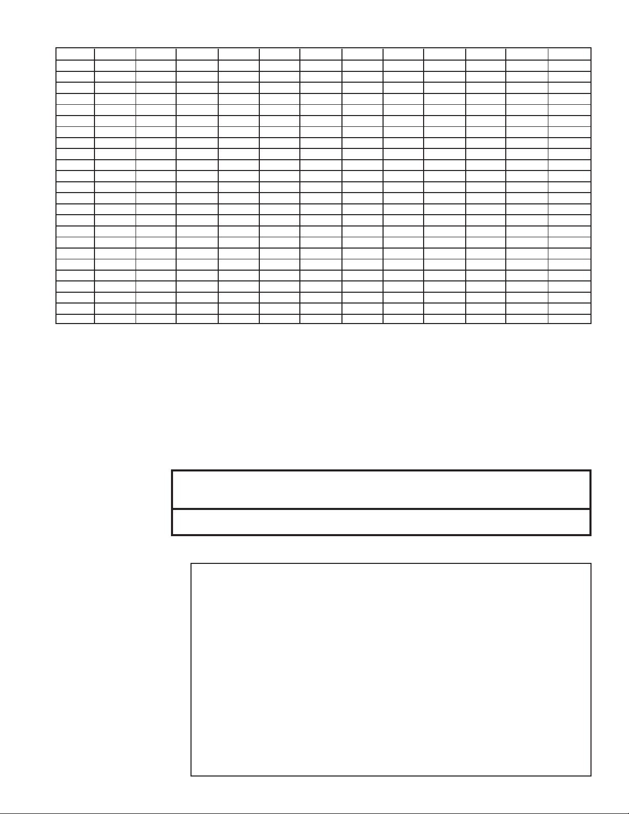
First Element of the Serial Number - Date of Manufacture
Year Jan Feb Mar Apr May June July Aug Sept Oct Nov Dec
1992 ARA ARB ARC ARD ARE ARF ARG ARH ARI ARJ ARK ARL
1993 ASA ASB ASC ASD ASE ASF ASG ASH ASI ASJ ASK ASL
1994 ATA ATB ATC ATD AT E ATF ATG ATH ATI ATJ ATK ATL
1995 AUA AUB AUC AUD AUE AUF AUG AUH AUI AUJ AUK AUL
1996 AVA AV B AV C AV D AV E AVF AV G AVH AVI AV J AV K AVL
1997 AWA AWB AWC AWD AWE AWF AWG AWH AWI AWJ AWK AWL
1998 AXA AXB AXC AXD AXE AXF AXG AXH AXI AXJ AXK AXL
1999 AYA AYB AYC AYD AYE AYF AYG AYH AYI AYJ AYK AYL
2000 AZA AZB AZC AZD AZE AZF AZG AZH AZI AZJ AZK AZL
2001 BAA BAB BAC BAD BAE BAF BAG BAH BAI BAJ BAK BAL
2002 BBA BBB BBC BBD BBE BBF BBG BBH BBI BBJ BBK BBL
2003 BCA BCB BCC BCD BCE BCF BCG BCH BCI BCJ BCK BCL
2004 BDA BDB` BDC BDD BDE BDF BDG BDH BDI BDJ BDK BDL
2005 BEA BEB BEC BED BEE BEF BEG BEH BEI BEJ BEK BEL
2006 BFA BFB BFC BFD BFE BFF BFG BFH BFI BFJ BFK BFL
2007 BGA BGB BGC BGD BGE BGF BGG BGH BGI BGJ BGK BGL
2008 BHA BHB BHC BHD BHE BHF BHG BHH BHI BHJ BHK BHL
2009 BIA BIB BIC BID BIE BIF BIG BIH BII BIJ BIK BIL
2010 BJA BJB BJC BJD BJE BJF BJG BJH BJI BJJ BJK BJL
2011 BKA BKB BKC BKD BKE BKF BKG BKH BKI BKJ BKK BKL
2012 BLA BLB BLC BLD BLE BLF BLG BLH BLI BLJ BLK BLL
2013 BMA BMB BMC BMD BME BMF BMG BMH BMI BMJ BMK BML
2014 BNA BNB BNC BND BNE BNF BNG BNH BNI BNJ BNK BNL
2015 BOA BOB BOC BOD BOE BOF BOG BOH BOI BOJ BOK BOL
Size Conversion Label - Models TR 75, 125, 175
When servicing a heater with a rating plate reading Model TR75, TR125, or TR175, always look for a Size Conversion label.
• Rating Plate reads Model TR75/ Size Conversion Label reads TR100 - Burner/control boxes originally ordered as Model TR-A or Model
TR75/100 include a factory-built Model TR75 and a field kit to convert to a Model TR100. A heater with Model TR75 rating plate and a Field
Conversion Label converting it to a Model TR100 is the same as a factory-built Model TR100.
• Rating Plate reads Model TR125/ Size Conversion Label reads TR150 - Burner/control boxes originally ordered as Model TR-C or Model
125/150 include a factory-built Model TR125 and a field kit to convert to a Model TR150. A heater with Model TR125 rating plate and a Field
Conversion Label converting it to a Model TR150 is the same as a factory-built Model TR150.
• Rating Plate reads Model TR175/ Size Conversion Label reads TR200 - Burner/control boxes originally ordered as Model TR-K or Model
TR 175/200 include a factory-built Model TR175 and a field kit to convert to a Model TR200. A heater with Model TR175 rating plate and a
Field Conversion Label converting it to a Model TR200 is the same as a factory-built Model TR200.
Example of a
Size Conversion
Label
Example of a
Replacement
Parts Tag
Replacement parts tags on Model
TR/TR-H and TRP heaters are for
your convenience in identifying replacement part numbers. Always
give the complete Model No., Serial No., and P/N with description
when ordering replacement parts.
This appliance has been converted at the time of installation to a Model 100 with Kit No.
120096 by __________________________________________________________________
who accepts the responsibility for the correctness of this conversion.
ORIFICE SIZE - #12 drill
NORMAL INPUT - 100,000 btu/hr
Minimum permissible gas supply pressure
for purposes of input adjustment - 4.5" w.c.
COMMON REPLACEMENT P ARTS FOR: REZNOR
MODEL TR75
SERIAL NUMBER ARI66M4N44585
WHEN ORDERING PART, ALWAYS GIVE THE FULL MODEL NUMBER AND SERIAL NUMBER
TRANSFORMER ....................................102709
PILOT .....................................................097534
SPARK IGNITION ..................................097782
TIME DELA Y RELAY..............................116044
BLOWER MOTOR .................................097738
BLOWER WHEEL .................................097724
PRESSURE SWITCH ............................120031
BURNER DOOR SWITCH .....................116023
BURNER ON LIGHT ..............................116045
OPTIONAL REPLACEMENT P ARTS:
4" INLET AIR CAP .................................120724
-- WARNING --
ALL PARTS ARE FOR USE WITH THE FUEL IDENTIFIED ON THE UNIT RATING PLATE. IF THE UNIT
HAS BEEN CONVERTED TO OTHER FUELS, CHECK WITH DEALER FOR PROPER FUEL-CARRYING
PARTS. INSTALLATION OF IMPROPER PARTS CAN CAUSE DEATH OR INJURY OR PROPERTY LOSS.
Form 709, page 3
Page 4
Burner/Control Box - Models TR/TR-H (Model TR-H is a for operation at elevations above
2000 ft. Unless specified, replacement parts apply to Both Model TR and TR-H)
Burner/Control Box and Non-Operating Components
Code Description Qty (other 50 7 5 100 125 150 175 200
than 1)
Gas Ignition System
1 Burner Natural Recycling Spark 125791 115953 120521 120297 120523 133246 133248
Control Box Natural Spark with Lockout 150000 150001 150002 150003 150004 150005 150006
Propane Spark with Lockout 125797 115997 120522 120298 120524 -- --
2 Burner Box Hanger 2 116030 116030 116030 116030 116030 116030 116030
3 Burner Box Door Assembly 125794 115964 115964 115964 115964 115964 115964
4 Draw/Pull Door Latch, Guden #832-02 2 120735 120735 120735 120735 120735 120735 120735
5 Combustion Air Inlet Cover Assembly 116040 116040 116040 116040 116040 133253 133253
6 Hardware Bag for attaching Burner/Control Box and Combustion 120348 120348 120348 120348 120348 120348 120348
Chamber Tube (includes 4 lockwashers, 4 nuts, 3 “S” hooks, 1
gasket (Code 6A), 2 bolts, 4 screws)
6A Combustion Chamber/Burner Box Gasket 116029 116029 116029 116029 116029 116029 116029
7 Hole Plug for Testing Port, Heyco #DP-875 (replaces P/N 120350) 16452 16452 16452 16452 16452 16452 16452
8 Vent Cap, 4" 110051 110051 110051 110051 110051 110051 110051
9 Combustion Air Restrictor Plate (also referred to as an air orifice plate)
Natural Gas, 0-2000 Ft Elevation (Model TR) U.S. & 125795 120354 120546 120355 120547 133166 133167
Propane Gas, 0-2000 Ft Elevation (Model TR) Canada 125795 120529 120546 120355 120547 -- --
Natural, 2001-4000 Ft (Model TR-H) 126072 120381 120382 120383 120384 133802 133803
Propane, 2001-4000 Ft (Model TR-H) U.S. 126072 120381 120382 120383 120384 -- - Natural, 4001-6000 Ft (Model TR-H) (ANSI 126075 120981 120982 120983 120984 133807 133808
Propane, 4001-6000 Ft (Model TR-H) Std) 126075 120981 120982 120983 120984 -- - Natural, 6001-8000 Ft (Model TR-H) 126081 120985 120986 120987 120988 133810 - Propane, 6001-8000 Ft (Model TR-H) 126081 120985 120986 120987 120988 -- - Natural, 2001-4500 Ft (Model TR-H) Canada 126072 120381 120382 120383 120384 133802 133803
Propane, 2001-4500 Ft (Model TR-H) (CGA Std) 126072 120381 120382 120383 120384 -- --
10 Sensing Tube with Bracket 115969 115969 115969 115969 115969 115969 115969
11 Pilot Mounting Bracket with Sensing Rod 120675 120675 120675 120675 120675 120675 120675
Code 1 - Burner/Control Box
22 (page 6)
5
7
3
gasket fits over the four studs; gasket
is not shown in this illustration.
Form 709, page 4
23 (page 6)
2
6A Square
Code 4 - Door
Latch
Code 8 - 4" Vent
Cap
Code 11 - Pilot
Mounting
Bracket with
Ground Rod
Ground
Rod
Codes 9 and 10
9 - Combustion
Air Restrictor
Plate
10 -
Combustion
Air Flow
Sensor
Bracket and
Tube
Burner/Control Box
Top View (with Top
Panel Removed)
14A/B -
Combustion Air/
Venter Motor and
Wheel Assembly
14D
14C
13
Code 14E Capacitor
Page 5
Combustion Air/Venter Blower and Motor (Model TR operates at 0-2000 ft elevation; Model TR-H above 2000 ft)
Code Description Model 50 75 100 125 150 175 200
13 Blower Housing TR 120999 120999 120999 120999 121861 132006 132006
Hi-Tech #360 Hi-Tech #360 Hi-Tech #360 Hi-Tech #360
TR-H 120999 120999 120999 121575 121575 132006 132006
Hi-Tech #360 Hi-Tech #360 Hi-Tech #360
14 Combustion Air/Venter TR 116002 116002 116002 116003 116003 132009 132009
Mtr & Wheel Assy TR-H 116002 116002 116002 121052 121052 132009 132009
(includes Codes 14A-G)
14A Motor - 115Volt TR & 97738 97738 97738 97741 97741 132058 132058
TR-H Universal Universal Universal Universal Universal Universal Universal
#JAIM156M #JAIM156M #JAIM156M #JEIE009N #JEIE009N #JE1F015N #JE1F015N
14B Motor - 208/230 Volt TR & 98157 98157 98157 98157 98157 98157 98157
TR-H Universal Universal Universal Universal Universal Universal Universal
#JEIE010N #JEIE010N #JEIE010N #JEIE010N #JEIE010N #JEIE010N #JEIE010N
14C Venter Wheel TR 97724 97724 97724 97724 97724 132007 132007
Brookside Brookside Brookside Brookside Brookside Brookside Brookside
#FE-400-200 #FE-400-200 #FE-400-200 #FE-400-200 #FE-400-200 #FE-610-216-1 #FE-610-216-1
TR-H 97724 97724 97724 120545 120545 132007 132007
Brookside Brookside Brookside Brookside Brookside Brookside Brookside
#FE-400-200 #FE-400-200 #FE-400-200 #FE-519-119-2 #FE-519-119-2 #FE-610-216-1 #FE-610-216-1
14D Motor Plate TR 97301 97301 97301 97301 97301 132019 132019
TR-H 97301 97301 97301 120997 120997 132019 132019
14E Motor Capacitor - TR & -- -- -- 163894 163894 163894 163894
4MFD @ 370V TR-H
14F Capacitor Boot - TR & -- -- -- 103182 103182 103182 103182
Syntex #M-78 TR-H
14G Spacers - #8 Spirol TR & (4)97721 (4)97721 (4)97721 (4)97722 (4)97722 (4)97722 (4)97722
TR-H 3/4"lg 3/4"lg 3/4"lg 15/16"lg 15/16"lg 15/16"lg 15/16"lg
Burner, Manifold and Orifices
Burner
Control
Box
16 -
Manifold
17- Burner Orifice
Code Description Model 50 75 100 125 150 175 200
15 Main Burner Assembly TR/TR-H 115973 115973 115973 115973 115973 132022 132022
16 Manifold & Manifold Bracket TR/TR-H 115981 115981 115981 115981 115981 115981 115981
17 Burner Natural TR 120146 120153 120157 120161 120165 120164 136200
Orifice 0-2000 ft 3.4mm #20 #12 #1 D C 6.75mm
Propane TR 124966 120137 120141 120145 120149 -- -0-2000 ft #45 #40 # 32 3.3mm #27
Natural TR-H 120147 120154 120158 131581 120166 120165 136201
Burner 2001-4000 ft #29 #19 #10 5.9mm E D 6.8mm
Orifice Propane TR-H 124967 120138 120142 120145 120150 -- -(Do not 2001-4000 ft 2.1mm #39 #3.0mm 3.3mm #26
use for Natural TR-H 124969 131579 120159 120162 120167 120166 136202
high altitude 4001-6000 ft #28 4.25mm 5.0mm A F E 7.0mm
conversion; Propane TR-H 124968 120139 120143 120146 120151 -- -high altitude 4001-6000 ft 2.15mm #38 #31 3.4mm 3.8mm
kits are on Natural TR-H 120149 120155 131580 120164 120168 120167 -page 8.) 6001-8000 ft #27 #18 #8 C G F
Propane TR-H 131578 120140 120144 120148 120152 -- --
6001-8000 ft 2.2mm #37 3.1mm 3.5mm #23
15 - Burner Assembly
Code 15 Main
Burner
Assembly
Code 17 Burner
Orifice
Select burner
orifice carefully .
Do not ream.
Code 16 - Manifold
Form 709, page 5
Page 6

Burner/Control Box (cont'd)
Electrical Components
Electrical Component Locations
18 - Door
Interlock Switch
20 - Ignition
Controller
21 Pressure
Switch
Transformer
26 Valve
19 Time
Delay
Relay
24 Power
Cord
25 -
Code 18 - Safety
Door Interlock
Switch
Code 20 - Ignition Controllers
Code 20A -
G67BG-5,
Ignition
Controller
(recycling)
Code 21 Pressure
Switch
Code 19 - Time
Delay Relay
Code 20B -
G770NGC-4,
Ignition
Controller with
lockout
Code Description Application P/N
18 SPST Switch (Door Interlock Switch), MCG 0815-9011 All Sizes 116023
19 Time Delay Relay, 24V, T.I. #60704A0-41 All Sizes 116044
20A Ignition Controller - Model G67BG-5 All Sizes 97782
20B Ignition Controller with lockout - Model G770NGC-4 All Sizes (required w/propane) 97547
21 Pressure Switch, Tri-Delta #PPS10138-2813 All Sizes 0-2000 ft elevation; 171825
Sizes 50-150 - 2001-6000 ft; (replaces
Sizes 75-150 - 6001-8000 ft 120031)
Pressure Switch, Tri Delta #PPS10138-2814 Sizes 175, 200 - 2001-6000 ft; 171826
Sizes 50, 175 - 6001-8000 ft (replaces
120322)
22 Indicator Light, Jemco #XL-9036-5JL, 24V (See page 4) All Sizes 116045
23 Terminal Strip, 2 Pole - Doran Mfg. Co (See page 4) All Sizes 96041
24 Power Cord 4’6", 115 volt, #068-32-41552 All Sizes 116046
Power Cord 4’6", 208/230 volt, NEMA 6-15P Sizes 50 - 150 120689
25 Transformer, 115V, 20 VA, Basler #BE141620-RAD 132204
(replaces
102709)
Transformer, 208/230V, 40VA, Basler #BE21537004 103500
Transformer, 115V, 35VA, Basler #BE141640-RAK 102708
26 Gas Valve - Natural, 1/2", Honeywell Model Sizes 50 - 150 96307
VR8204-M1000
Gas Valve - Propane, 1/2", Honeywell Model Sizes 50 - 150 96310
VR8204-M1018
Gas Valve - Natural, 1/2", Honeywell Model Sizes 175-200 136193
VR8304-M2824
27 Replacement Pilot Assy (for natural or propane, Size 50 110854
0-6000 ft) - see page 7 for components and Sizes 75 - 200 110853
pilots for altitudes above 6000 ft
Code 26 - Gas
Valve
Sizes Gas P/N
50-100 Natural 170609
125-150 Natural 96307
50-150 Propane 96310
175-200 Natural 136193
Form 709, page 6
Page 7

Code 27 Spark Pilot
Code Size Elevation Gas P/N Component Description
27A 50 0-6000 Natural 126060 Pilot Assy with orifice, pilot tubing, flame rod, less flame sensor
lead and fitting
75-200 0-6000 Natural 97534 Pilot Assy with orifice, pilot tubing, flame rod, less flame sensor
50-150 0-6000 Propane ead and fitting, Johnson #J982HKW-9733-715
50-150 6001-8000 Propane
50-175 6001-8000 Natural 126060 Pilot Assy with orifice, pilot tubing, flame rod, less flame sensor
ead and fitting
27B 50-200 0-6000 Natural 103034 Orifice only, Johnson #9731-715 (brass)
50-150 0-6000 Propane
50-150 6001-8000 Propane
50-175 6001-8000 Natural 134507 Orifice only, Johnson #7721D (red)
27C All 0-8000 Natural 98698 Pilot Tubing, Johnson #B10499-995-11, 1/8" O.D. x 18" long
27D and 97572 Compression fitting, FTG75 (2 required when replacing pilot tubing)
27E Propane 98697 Flame Rod, Johnson #Y57AA-3
27F 97575 Flame Sensor Lead, 21"
Tubular System (Tubes, Reflectors, and Hardware) - Models TR/TR-H
Code Description P/N
34 Combustion Chamber Tube only 123196
35 Heat Exchanger Tube only - 10' straight 123198
36 Tail Pipe Tube 123200
37 Tube Connection Hardware Bag (see illustration 116017
below, for components)
38A Turbulator Section - 37-1/8" 116019
38B Turbulator Section - 26" 120538
39 Reflector Bracket 131787
40 Reflector Retainer 131786
41 U-Bolt with brass nuts, 131785
3/8-16 x 4-1/2
42 Reflector only for straight 10' tube 123202
See illustration
below for kit
numbers.
Code 34 Combustion
Chamber Tube
Code 35 Heat
Exchanger
Tube
Code 36 Tail Pipe
Tube
Code Description P/N
43 Reflector End Cap with Hardware Bag (Same as 143563
Option CD27) - use only gap cover kits, Code 44
44 Reflector Gap Cover Kits (Same as Options See list
CD21-26 for 20'-70' tube lengths) on page 8
45 “L” Heat Exchanger Tube with Reflector (Same as 120713
Option UC2) (component listing on page 8)
46 “U” Heat Exchanger Tube with Reflector (Same as 120712
Option UB3) (component listing on page 8)
47 Package containing 5' Heat Exchanger Tube with 125184
Reflector (Same as Option UA1) (not illustrated)
47A Heat Exchanger Tube only - 5' straight 125185
47B Reflector only for straight 5' tube 125186
Code 37 - Tube Connection Hardware
37C - Nuts 3/8-16, P/N 120746
37A Clamping
37B - Bolts,
P/N 114350
Rings, P/N
116008
37D - Lockwashers,
P/N 5197
Code 42 - Reflector
Codes 38A and B Turbulator Section
Codes 39, 40, and 41 Reflector Bracket, Retainer
and Hardware
Complete Kit for 1 Tube, P/N 136128
Complete Kit for 2 Tubes, P/N 136129
Complete Kit for 3 Tubes, P/N 136130
Code 43 - Reflector End Cover
39
41
40
Reflector end cover must
be used with reflector gap
covers (Code 44). End
cover cannot be installed
on a tube without a gap
cover.
Form 709, page 7
Page 8

Tubular System - Models TR/TR-H (cont'd)
Code 44 - Reflector Gap Covers
No. of Same as
Tubes Option P/N
2 CD21 143500
3 CD22 143501
4 CD23 143502
5 CD24 143503
6 CD25 143504
7 CD26 143505
Code 45 - "L" Heat Exchanger Tube Package
with Reflector (Same as Option UC2)
Code 46 - "U" Heat Exchanger Tube Package (Same as Option UB3)
46C
46E
46D
46B
46F
46A
Code Qty P/N Component Description
46A 1 120534 “U” Heat Exchanger Tube
Components -- "L" Tube only,
P/N 120535; "L" Tube Reflector
Right Half, P/N 144415; "L"
Tube Reflector Left Half, P/N
144416; "L" Tube Reflector Side,
P/N 144417; Reflector Hardware
Bag, P/N 143474
46B 1 116017 Tube Connecting Hardware Bag
46C 1 120993 Reflector T op
46D 1 120994 Reflector Right Side
46E 1 120995 Reflector Left Side
46F 1 120719 Reflector Hardware Bag including:14 - P/N 113275,
Screws #10-32 x 1/2" lg; 2 - P/N 113807, Washers;
14 - P/N 26490, Nuts Kep #10-32
T ubular System Car tons and Packaging Scheme
48 Tubular System Package , P/N 120294, includes
Qty Code P/N Description Qty Code P/N Description Qty Code P/N Description
1 34 123196 Combustion Chamber Tube 1 36 123200 Tail Pipe Tube 4 39 131787 Reflector Bracket
4 40 131786 Reflector Retainer 4 4 1 131785 U-Bolt w/brass nuts 2 42 123202 Reflectors
3 38A 116019 Turbulator 1 38B 120538 Turbulator 1 37 116017 Tube Connection Hardware Bag
49 Tubular System Package , P/N 120295, includes
Qty Code P/N Description Qty Code P/N Description Qty Code P/N Description
1 34 123196 Combustion Chamber Tube 1 35 123198 Heat Exchanger Tube 1 36 123200 Tail Pipe Tube
6 39 131787 Reflector Bracket 6 40 131786 Reflector Retainer 6 41 131785 U-Bolt w/brass nuts
3 42 123202 Reflectors 3 38A 116019 Turbulator 2 37 116017 Tube Connection Hardware Bag
50 Tubular System Package , P/N 120296, includes
Qty Code P/N Description Qty Code P/N Description Qty Code P/N Description
2 35 123198 Heat Exchanger Tube 4 39 131787 Reflector Bracket 4 40 131786 Reflector Retainer
4 41 131785 U-Bolt with brass nuts 2 42 123202 Reflectors 2 37 116017 Tube Connection Hardware Bag
2 38A 116019 Turbulator
Tube Packages above Required by Length of System
Length of Tubular System 20ft 30ft 40ft 50ft 60ft 70ft
Required Pkgs by Codes above (1) Code 48 (1) Code 49 (1) Code 48 (1) Code 49 (1) Code 48 (1) Code 49
(quantity in parenthesis) (1) Code 50 (1) Code 50 (2) Code 50 (2) Code 50
High Altitude and Gas Conversion Kits - Model TR
Code 51 - High Altitude Conversion Kits for Model TR
Type of Gas Natural Gas Propane Gas
BTUH Size 50 75 100 125* 150* 175 200 50 75 100 125* 150*
Elevation 2001-4000 feet (611-1219 meters)
Pkg P/N
Elevation 4001-6000 feet (1220-1829 meters)
Pkg P/N
Elevation 6001-8000 feet (1830-2438 me ters)
Pkg P/N
Code 52 - Gas Conversion Kits for Model TR (sea level only)
Sizes Natural to Propane Propane to Natural
TR 75 and 100 193859 193861
TR 125 and 150 193860 193862
NOTES: Gas conversion kits are not available for Size 50.
Sizes 175 and 200 are available for use with natural gas only.
Form 709, page 8
126440 120880 120882 132664 132667 132670 132673 126441 120881 120883 132676 132679
126442 120884 120886 132682 132685 132688 132691 126443 120885 120887 132694 132697
126444 120888 120890 132700 132703 132706 -- 126445 120889 120891 132712 132715
IMPORTANT: When selecting a gas conversion kit, check
Rating plate information
For size conversion label (see page 2)
For altitude conversion label (gas conversion kits are not available
for high altitude; consult the factory)
* Sizes 125 and 150 - Do not install a
High Altitude Conversion Kit in a
Size 125 or 150 heater that is factory
built for operation at sea level (0-2000
ft elevation). These kits for Size 125
and 150 heaters are designed only to
change the elevation range of a heater
that is factory-built for operation
above 2000 ft.
Page 9

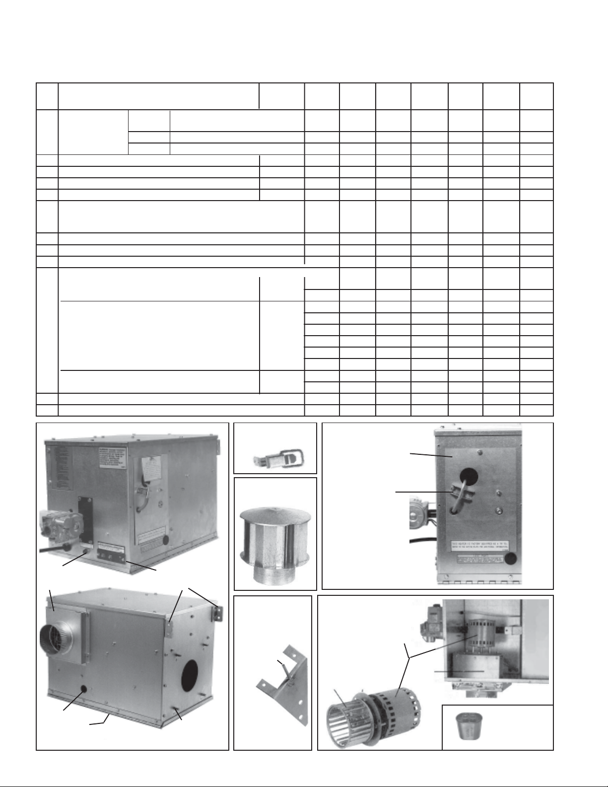
Replacement Parts - Model TRP
Model TRP
96
89 or
95
94
90
88
65
59
67
66
97
93
87
74
84
68
92
Optional Side Shield,
see Code 114, page14
Optional Side Shield,
see Code 114, page14
Code 59A Draw/Pull
Door Latch,
P/N 120735
Code De scription 30 50 60 100
57
Complete Burner Box Assy - standard unit (natural gas, power vent, indoor)
Burner Box Panel Assy with viewport (1)173847 (1)173847 (1)173849 (1)173849
58
Burner Box Top & Sides Assy (1)173872 (1)173874 (1)173873 (1)173875
59
Burner Box T op & Sides Ass y - Option AV5 (includes air inlet collar)
Burner Box Top & Sides Assy for Outdoor unit - Op tion AYW2
Draw/Pull Door Latch (2)120735 (2)120735 (2)120735 (2)120735
59A
To p Rainhood and Gasket Assy - Outdoor unit, Option AYW2 (see pg 10)
60
Self-adhesive tube gasket, 1/8" (not illustrated)
61
Burner Box Door Assembly (1)173636 (1)173636 (1)173638 (1)173638
62
Neoprene Gaskets
63
for Door Opening
Door Rainhood and Gasket Assy - Outdoor unit, Option AYW2 (see pg 10)
64
Burner Box Hang er (1)173856 (1)173856 (1)173858 (1)173858
65
Flue Collar, 4" (1)147220 (1)147220 (1)147220 (1)173891
66
Flue Collar Gasket (1)174265 (1)174265 (1)174265 (1)174264
67
Flue Wrapper Assy (1)173641 (1)173666 (1)173665 (1)173664
68
To p/Btm Flue Wrapper Gasket (2)173669 (2)173669 (2)173668 (2)173668
68A
Side Flue Wrapper Gasket (2)173667 (2)173667 (2)173876 (2)173876
68B
Venter Housing Assembly with gasket
69
Static Pressure Tap
69A
16" x 12" x 24" -- -- (2)173689 (2)173689
16" x 12" x 18" (2)173690 (2)173690 -- --
3/16" x 12" x 9" (2)173691 (2)173691 (2)173691 (2)173691
illustrated)
173868 173869 173870 173871
(1)174252 (1)174253 (1)174254 (1)174255
(1)175851 (1)175852 (1)175853 (1)175854
(1)175859 (1)175859 (1)175860 (1)175860
(2)173705 (2)173705 (4)173705 (4)173705
(1)175430 (1)175430 (1)175430 (1)175430
(not
(1)173713 (1)173851 (1)173854 (1)173855
(1)116043 (1)116043 (1)116043 (1)116043
91
58
75
78
72
64
73
62
71
69
Control
Panel
Code 71 - Venter Motor and Wheel Assembly
71C
71A
71G Fan (centered with hub
away from motor)
71H
71J
71E
71B
Code Description 30 50 60 100
Venter Mtr & Wheel Assy (1)174017 (1) 174017 (1)174 017 (1)121052
71
Venter Motor (1)148055 (1) 148055 (1)148 055 (1)148053
71A
Venter Wheel (1)135979 (1)135979 (1)1 35979 (1)120545
71B
Venter Motor Capacitor -- -- -- (1)163894
71C
Capacitor Boot -- -- -- (1)103182
71D
Motor Mounting Plate (1)174275 (1)174275 (1)174275 (1)120997
71E
Mtr Mntng Plate Gasket (1)155651 (1)155651 (1)155651 --
71F
Fan Blade (1)68005 (1)68005 (1)68005 (1)68005
71G
Spacers (4)97721 (4)97721 (4)97721 (4)97722
71H
#8 x 3/4" long
Kep Nut #8-32 (4)31522 (4)31522 (4)31522 (5)31522
71J
#8x15/16" lg
Form 709, page 9
Page 10

Replacement Parts - Model TRP (cont'd)
Model TRP
showing the
outdoor burner
box parts (Part
of Option
AYW2)
Code 76 Spark
Electrode
Assy with
24" Lead,
P/N 173878
65 - Hanger
Angle
64 - Door
Rainhood
Assembly
Code 77 Flame
Sensor,
P/N 147165
60 - Top
Rainhood
Assembly
Burner
Box
Model TRP showing burner box with optional separated
combustion (Option AV5)
Inlet Air Collar for Separated
Combustion (Option AV5)
Burner
Rack
Assembly
Code 80 - Gas Valve
78 - Manifold
Natural Gas Valve for TRP 30, 50, 60,
P/N 172552, Honeywell VR8105M2187
(illustrated)
74 - Sealed Wall for Separated
Combustion (Option AV5)
73 - Manifold Cover
Plate for Separated
Combustion
(Option AV5)
80 Gas
Valve
Manifold
and Control
Assembly
Natural Gas Valve for TRP 100,
P/N 147830, Honeywell VR8205M1130
Propane Gas Valve for TRP 30, 50, 60,
P/N 172553, Honeywell VR8105RM2825
Propane Gas Valve for TRP 100,
P/N 147560, Honeywell VR8205M1148
Code 82 -
T ransformer, 30
VA, 120V/24V,
P/N 147356
Model TRP
Control
Compartment
NOTE: The
burner box
illustrated is for a
Model TRP 60 or
100 having dual
burners with a
center carryover.
Models TRP 30
and 50 have a
single burner.
Form 709, page 10
Code 83 Integrated
Control
Module,
P/N 174260
77
75D
Code 84 Pressure Switch
75C
76
Pressure Switch for TRP 30, 0 to 4000 ft elevation,
P/N 174020
Pressure Switch for TRP 50, 60, 100, 0 to 4000 ft
elevation, P/N 174435
Pressure Switch for TRP 30, over 4000 ft elevation,
P/N 174420
Pressure Switch for TRP 50, 60, 100, over 4000 ft
elevation, P/N 174436
84
71
80
82
83
Page 11

Code 30 50 60 100
Seal Plate - Optio n AV5 ( sepa rated co mbustion )
72
Manifold Cover Plate with Gasket - Option AV5 (separated combustion) (1)174025 (1)174026 (1)174025 (1)174026
73
Wall - Option AV5 (separated-combustion) only
74
Burner Rack Assy
75
Burner Rack Mounting Bracket
75A
Burner Support
75B
Burner, Beckett #10920X
75C
Carryover Burner Assy
75D
Ignitor/Sensor Bracket (not illustrated)
75E
Spark Electrode Assy with 24" lead
76
Flame Sensor
77
Manifold
78
79
Gas Valv e, Honeywell, 1/2" x 1/2", 3.5" w.c., 24V, na tural gas
80
(For propane to natural gas conversion kits, see Code 108, page 12.)
Gas Valve, Honeywell, 1/2" x 1/2", 24V, propane gas
(For natural to propane gas conversion kits, see Code 107, page 12.)
Orifice for Carryover Burner, natural gas, J/C #7715 (not illustrated)
81
Orifice for Carryover Burner, propane gas, J/C #9733 (not illustrated)
Transformer, 30VA, 120V/24V
82
Integrated Control M odule
83
Pressure Switch, 0 to 4000 ft elevation
84
Pressure Switch, over 4000 ft elevation
Silicone Sensor Tubing 3/16" x 13" - all (1)123727 (1)123727 (1)123727 (1)123727
85
Description
(1)173672 (1)173672 (1)173672 (1)173672
(1)173670 (1)173671 (1)173670 (1)173671
175290 175291 175292 175293
(2)174046 (2)174045 (2)174046 (2)174045
(1)174047 (1)174047 (1)174048 (1)174048
(1)173618 (1)173618 (2)173618 (2)173618
-- -- (1)173639 (1)173639
(1)173845 (1)173845 (1)174050 (1)174050
(1)173878 (1)173878 (1)173878 (1)173878
(1)147165 (1)147165 (1)147165 (1)147165
(1)173613 (1)173613 (1)173614 (1)173614
See table on page 12.Burner Orifice
(1)172552 (1)172552 (1)172552 (1)147830
VR8105M2187
VR8205M1130
(1)172553 (1)172553 (1)172553 (1)147560
VR8105RM2825
VR82051148
-- -- (1)93973 (1)93973
-- -- (1)98695 (1)98695
(1)147356 (1)147356 (1)147356 (1)147356
(1)174260 (1)174260 (1)174260 (1)174260
(1)174020 (1)174435 (1)174435 (1)174435
(1)174420 (1)174436 (1)174436 (1)174436
Silicone Sensor Tubing 3/16" x 4" - Option AV5, separated combustion (1)113774 (1)113774 (1)113774 (1)113774
Silicone Sensor Tubing 3/16" x 5-1/4" - Option AV5, separated combustion (1)123728 (1)123728 (1)123728 (1)123728
Power Supply Cord, 3.5 ft, Indoor (not illustrated)
86
Power Supply Cord, 3.5 ft, Outdoor (Option AYW2) (not illustrated)
Refer to illustration on page 9 to identify Codes 87-99
NOTE:
Heat Exchanger & Reflector Assy (includes turning box; for replacement turning box
87
(1)116046 (1)116046 (1)116046 (1)116046
(1)173692 (1)173692 (1)173692 (1)173692
(1)173866 (1)173867 (1)173861 (1)173678
only, see Code 97) - 1st Section (next to burner box) or only section Sizes 30 & 60
Reflector
88
Reflect or End Cap
89
Mid Hanger
90
Turbulator Type 1
91
Turbulator Type 2
92
Heat Exchanger & Reflector Assy (includes turning box; for replacement turning box
93
(1)173686 (1)173687 (1)173699 (1)173700
(1)173701 -- (1)173702 -(1)173857 (1)173857 (1)173859 (1)173859
(1)173881 (1)173881 (2)173881 (2)173881
(1)173882 (1)173882 (2)173882 (2)173882
-- (1)174019 -- (1)173896
only, see Code 97) - 2nd Section (next to turning end) on Sizes 50 and 100
Reflector
94
Reflect or End Cap
95
Mid Hanger
96
Replacement Turning Box Assy
97
Top/Btm Turning Box Gskt (not illustrated)
98
Side Turning Box Gskt (not illustrated)
99
Hinge (connects the center plates of the two heat exchanger sections -- (1)173615 -- (1)173616
100
-- (1)173686 -- (1)173699
-- (1)173701 -- (1)173702
-- (1)173857 -- (1)173859
(1)173649 (1)173649 (1)173650 (1)173650
(2)173853 (2)173853 (2)173659 (2)173659
(2)173658 (2)173658 (2)173658 (2)173658
on Sizes 50 and 100 - See Code 101 for field-installed hardware) 18" long 24" long
Hardware for Attaching Center Plates on Sizes 50 and 100:
101
Lockwasher
Nuts
Self-adhesive Tube
Gasket, 1/8" thick
1/4" Kep Nut
-- (2)173705 -- (4)173705
-- (6)7328 -- (6)7328
Flat Washer
Bolt
1/4" x 3/4" long
Hex Head Bolt
-- (6)16246 -- (6)16246
1/4" Flat Washer
-- (6)1320 -- (6)1320
Code 100 - Hinge
1/0 Double Loop Chain (Sizes 30 & 60 - 25 ft chain; Sizes 50 & 100 - 50 ft chain) (1)173693 (1)120703 (1)173693 (1)120703
102
"S" Hooks 1/4" (8)116034 (12)116034 (8)116034 (12)116034
103
1/4" Lockwasher
-- (6)1319 -- (6)1319
Form 709, page 11
Page 12

Replacement Parts - Model TRP (cont'd)
Code 79 - Burner Orifices
Model TRP 30 50 60 100
BURNER ORIFICES
Natural G as, 0-2000 ft
Propane Gas, 0-2000 ft
For instal- N atural 2001lation Gas 4500Siz e
in Propane ft
Canada Gas Size
For instal- N atural 2001lation Gas 3000Siz e
in Propane ft
U.S.A. G as Size
Natural 3001Gas 4000Siz e
Propane ft
Gas Size
NOTE: Natural 4001Above Gas 5000Siz e
4000 ft Pr opa ne ft
requires Gas Size
pressure Natural 5001switch Gas 6000 Size
change. Propane ft
See Gas Size
Code Natural 600184 on Gas 7000 Size
page 11. Propane ft
Gas Size
Natural 7001Gas 8000 Size
Propane ft
Gas Size
Natural 8001Gas 9000 Size
Propane ft
Gas Size
Qty 1122
11835 173846 11835 173846
P/N
Siz e
Siz e
#37 3.4 mm #37 3.4 mm
97631 16590 97631 16590
P/N
1.6mm #46 1.6mm #46
45871 173846 45871 173846
P/N
#39 3.4mm #39 3.4mm
9789 84853 9789 84853
P/N
#53 #47 #53 #47
45870 173846 45870 173846
P/N
#38 3.4mm #38 3.4mm
97631 84853 97631 84853
P/N
1.6mm #47 1.6mm #47
45871 173846 45871 173846
P/N
#39 3.4mm #39 3.4mm
9789 84853 9789 84853
P/N
#53 #47 #53 #47
45871 173846 45871 173846
P/N
#39 3.4mm #39 3.4mm
9789 84853 9789 84853
P/N
#53 #47 #53 #47
87391 26112 87391 26112
P/N
#40 #30 #40 #30
9789 40414 9789 40414
P/N
#53 #48 #53 #48
11792 26112 11792 26112
P/N
#41 #30 #41 #30
9789 40414 9789 40414
P/N
#53 #48 #53 #48
84437 26113 84437 26113
P/N
#42 #31 #42 #31
9789 39651 9789 39651
P/N
#53 #49 #53 #49
84437 26113 84437 26113
P/N
#42 #31 #42 #31
11834 39651 11834 39651
P/N
#54 #49 #54 #49
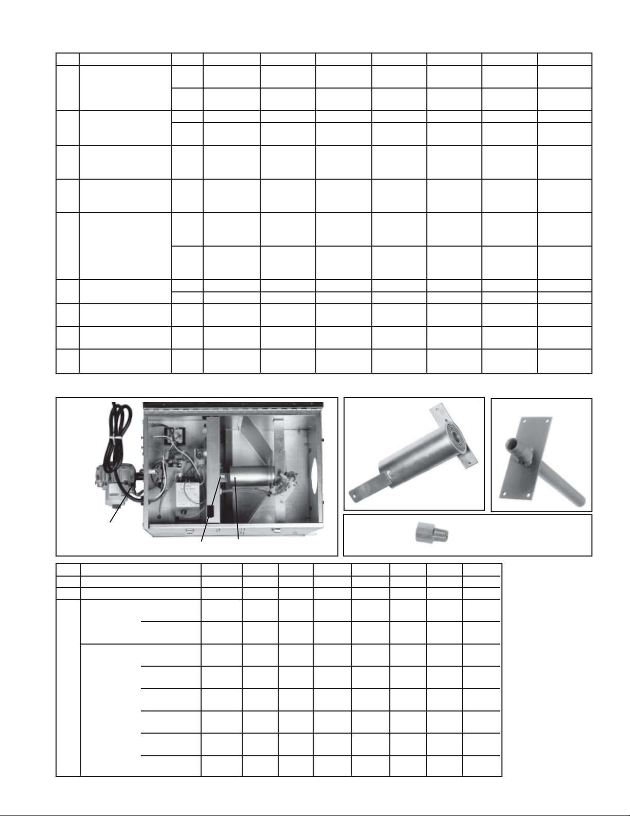
Components of Code 104, Option CC6, Horizontal Vent
Terminal/Combustion Air Packages for Optional
Separated Combustion:
Qty Description 30, 50, 60 100
Complete Horizontal Vent Kit 157157 157158
(Same as Option CC6)
1 Concentric 155118 155392
Box
Assembly
1 Screened 155096 155096
Exhaust
Assembly
1 Inlet 151755 151755
Guard
4 #10-16x1/2" lg Screws (to 37661 37661
attach the inlet guard)
1 4" I.D. Rubber Seal 164492 164492
1 Tube of High Temperature 53335 53335
Silicone Rubber Sealant
Components of Code 105, Option CC2, Vertical Vent
Terminal/Combustion Air Packages for Optional
Separated Combustion:
Qty Description 30, 50, 60 100
Complete V ertical Vent Kit 157155 157156
(Same as Option CC2)
1 Concentric 155118 155392
Box
Assembly
1 Exhaust 155631 155631
Terminal
1 Combustion 155635 155635
Air Inlet
1 4" I.D. Rubber Seal 164492 164492
1 Tube of High Temperature 53335 53335
Kits and Accessories - Model TRP
Code 30 50 60 100
104 Horizontal Combustion Air Inlet
/Vent Concentric A dapter and
Terminal Kit (same as Opt CC6)
105 Vertical Combustion Air Inlet
/Vent Concentric A dapter and
Terminal Kit (same as Opt CC2)
106 Vent Cap, 4", Same as Option CC1 110051 110051 110051 110051
Gas Conversion Kits - Natural to
107 for Model TRP heaters
Propane
Gas Conversion Kits - Propane to Natural for all Model TRP
108 175617 175618 175617 175618
Form 709, page 12
Kits and Components
Option CC2 or CC6 is
required with Opt AV5,
separated combustion. See
components above.
with standard power vent
for heaters with optional
separated combustion
157157 157157 157157 157158
157155 157155 157155 157156
175610 175611 175612 175613
175610 175611 175612 175624
(Opt AV5)
Silicone Rubber Sealant
Code 106 4" Vent Cap
(Same as
Option CC1;
required on
outdoor unit)
Page 13

Options and Accessories - Apply to Models TR/TRH and/or Model
TRP as indicated
Code 109 - Single-Stage Thermostat, W/R #1C30-341
(Same as Option CL1), P/N 91919 - Applies to Models
TR, TR/H, and TRP
24 Volt
40-80° F Range
Snap Action Contacts
30 V.A.C. Maximum
.15 to 1.0 Amps
Adjustable Anticipator
Vertical Mounting with Wall Mounting Plate
Dial "off" Switch
Code Description (see illustrations below and on page 14) Applies to Model P/N
111 Complete Combustion Air Inlet Kit (Same as Option DE2) TR and TR/H 120724
112 Dual Vent Kit (Same as Option CC5) - See illustration below for components TR, TR/H, and TRP 120736
113 Turnbuckle, Forged Carbon Steel, #10704, with Lock Nut (part of Options CK 12-18) TR, TR/H, and TRP 120704
114 Side Shield Package (hangs along rear of tubular system) TR, TR/H, and TRP See List
115 Multiple Heater Control Pkg (for 115V master and one slave, same as Option CL31) TR and TR/H 102248
116 Multiple Heater Control Pkg (for 208/230V master & all slave units, same as Option CL32) TR and TR/H 102249
117 Thermostat Bracket Package for Heater Mounting (Same as Option CM3) TR and TR/H 98524
118 Gas Connector, 1/2" Flexible, 24" long Stainless (Same as Option CE3) TR, TR/H, and TRP 120715
Gas Connector, 3/4" Flexible, 24" long Stainless (Same as Option CE4) TR, TR/H, and TRP 120874
119 Hanger Chain Kit (Same as Option CK11) TR and TR/H 120698
Components: Hanging Chain, 50 ft, 200 lb load, P/N 120703; (For chain and hooks for TRP, see
“S” Hook, 1/4", Campbell #610-8024, P/N 116034 Codes 101 and 102, page 11.)
Code 110 - Thermostat Cover, W/R 29-0143 (Same as Option
CM1), P/N 91926- Applies to Models TR, TR/H, and TRP
Clear Plastic
Locking Cover
Code 111 - Combustion Air Inlet Kit (Same as Option
DE2 for TR and TR/H)
Code 112 - Dual
Vent Kit (Same
as Option CC5
for TR, TR/H,
and TRP)
111C
111B
Code Qty P/N Component Description
111A 1 120729 Expandable Combustion Air Inlet Pipe, 4" dia.
111B 2 120716 Clamp, Worm Drive, 1/2" Stainless Steel
111C 1 120726 Inlet Cap, 4"
111A
Code Qty P/N Component Description
112A 1 120291 Dual Vent Adapter Box
112B 1 110051 4" Vent Cap
112C 1 120869 6" Vent Cap
112D 1 53335 Tube of Silicone Rubber
112E 2 120108 Support Angles
Code 113, Turnbuckle and Turnbuckle Lock Nut for Models TR, TR-H, and TRP
Right
Hand
Thread
Turnbuckle Lock Nut
Add nut to turnbuckle; do not lock
the nut against the turnbuckle until the system is leveled.
T urnbuckle assembly rated
for a 200-lb working load
Left Hand Thread
Each package (kit) includes equal quantities of:
Eye-to-Eye Turnbuckle of forged carbon steel,
P/N 120704, and 5/16-18 Nut (Kep), P/N 6554
Model
TR/TR-H
TRP 30 & 60
TRP 50 & 100
Straight System Configuration
Tube Straight or "L" "U"
Length Option Package Qty Option Package Qty
(fe et) No. P/N per pkg No. P/N per pkg
20 CK12
30 CK13
40 CK14
50 CK15
60 CK16
70 CK17
N/A CK12
N/A CK14
112A
120699
121045
120700
121046
120701
121047
120699
120700
112D
112E
4CK13
5CK14
6CK15
7CK16
8CK17
9CK18
4
6
112B
112C
121045
120700
121046
120701
121047
132517
Form 709, page 13
5
6
7
8
9
10
Page 14

Options and Accessories - Apply to Models TR/TRH and/or Model
Screw (remove
and discard)
Terminal Strip
B
E
A
F
C
D
B
Screw (remove
and discard)
TRP as indicated (cont'd)
Code 114 - Optional Side Shield Kits
Side Shield Kits for Models TR and
TR/H
Reflector
Retainer
Side Shield
Reflector
Tube
U-Bolt
Reflector Bracket
Side Shield Kits
for Model TRP
Side Shield Option Kits for Model TRP heaters:
Option CD30 CD31
Applies to TRP 30 & 60 TRP 50 & 100
U Type
Fastener
Flat
Washer
Reflector
Option Pkg P/N 175288 175289
Qty P/N Qty P/N
Side Shield 2 173888 2 173888
2 173892
U-T ype Nut 4 1849 8 1849
Screw
Side
Shield
1/4" Flat Washer 4 1320 8 1320
Sheetmetal Screw 4 11813 8 11813
#10 x 1/2"
Length of Shielded Tubes - Models TR and TR/H
5' 10' 20' 30' 40' 50' 60' 70'
Option Designati on CD19 CD13 CD14 CD15 CD16 CD17 CD18 CD20
Option Package P/N 125340 120132 120705 120706 120707 120708 120709 132059
Qty P/N Qty P/N Qty P/N Qty P/N Qty P/N Qty P/N Qty P/N Qty P/N
Side Shield Modular Section 1 116020 2 116020 4 116020 6 116020 8 116020 10 116020 12 116020 14 116020
Reflector Bracket 0 2 131787 4 131787 6 131787 8 131787 10 131787 12 131787 14 131787
U-Bolt with two Brass Nuts 0 2 131785 4 131785 6 131785 8 131785 10 131785 12 131785 14 131785
Reflector Retainer 0 2 131786 4 131786 6 131786 8 131786 10 131786 12 131786 14 131786
#10-32 x 1/2" long Screw 1 113275 1 113275 2 113275 3 113275 4 113275 5 113275 6 113275 7 113275
Form 709, page 14
Codes 115 and 116 - Multiple Heater Control Packages (Same as
Options CL31 and CL32 for Models TR and TR/H)
CL31 CL32 P/N Component
A 1 -- 102708 Transformer 35VA, Basler #BE141640-RAK
B 2 -- 103152 Sheet Metal Screws, #6 x 1-3/4" lg (to hold
transformer)
C 2 1 102243 RBM Relay Assembly consisting of one P/N
98118 RBM Relay (WR #134-20102-101)
wired & mounted on a specially designed bracket
D 2 1 16228 Cable Clamp 3/16"
E 2 1 131127 Wiring Diagram Label
G 4 2 121033 Screws, #8 x 1" lg
F 4 2 98872 Spacers
NOTE: Pkg P/N
102248 also includes
two Tinnerman clips
which are not used on
Model TR. Pkg covers
multiple product lines.
Remove Screw
E
Terminal Strip
Remove Screw
F
G
C
D
Code 117 Thermostat
Bracket
Package (Same
as Option CM3)
Qty P/ N Component
A 1 98353 Bracket
B 2 3618 Chase Nipple,
1/2", T&B #842
C 1 7447 Coupling Conduit
Connector, 1/2"
D 1 17782 Outlet Box, 2" x 4"
E 2 98872 Spacer, 1/4"x7/16"lg,
Spirol #SP100
F 2 121033 Screws, #8 x 1" long
Code 119 -
1/2", P/N 120715; 3/4", P/N 120874
Flexible Gas
Connector
(Options CE3
and CE4 for TR,
TR/H and TRP)
Page 15

High-Intensity Infrared Models RIH/RIHV
A
D
B
C
Degree of Angle Mounting
12 Length Chain
with S Hooks
#5 S Hook (typical)
Adjust length
to change
mounting
angle.
Controls - All RIH/RIHV High-Intensity Infrared Models
125
126
126
120
122
123
121
Code P/N Description
120 112044 Main Valve (115V) - 1/2" NPT, 002-42-01536C01A284 (natural and propane)
121 96010 Ignition Detection Control, Mark 10X-117, #132075-2, Pkg R9
122 96011 Wire Harness, #132084, Pkg R10
123 112045 Ignition Detection Control Mounting Bracket, #000K-1-016
124 112046 Ignitor, #0002-42-110
125 Conduit, 3/8" Greenfield with Anti-Short Bushings
112047 for RIHN30, RIHN60, RIHL50, #3802-95-300-01
112048 for RIHVN 100, RIHVL90, #3802-95-300-02
112049 for RIHVN 150, RIHVL 120, #3802-95-300-03
112050 for RIHVN 160, #3802-95-300-04
126 112051 Angle Connector for 3/8" Greenfield, #3802-95-302
124
Miscellaneous Replacement Parts and Accessories - Models RIH/RIHV
Description Same as P/N
Option
Chain - 50', 200 lb with 14 "S" Hooks UE-1 95995
Chain Hanging Kit - see illustration UE-2 110253
and instructions on the right
Stainless Flex Gas Connector, 24", UF-2 96000
7/8" O.D. with 1/2 gas cock with
pressure tap
Single-Stage Thermostat CL34 110252
- see illustration below
Single-Stage Thermostat, P/N 110252
115/24 Volt
50-90oF Range
Snap Action Switch
Vertical Mounting
Mfg #132026-1
Chain Hanging Kit,
P/N 110253
Instructions:
1) Hang full length chain at
desired height and attach
heater (C) with S-hooks
2) Attach one end of the 1'
length chain with S-hooks to
front of heater (D).
3) Place other end of chain with
S-hook in hook (B) on the
full length chain.
4) Change degree of angle by
moving "S" hook at point B.
5) Check to be sure unit is level.
Crimp all "S" hooks closed.
Form 709, page 15
Page 16

Miscellaneous Replacement Parts and Accessories (cont'd) - Models RIH/RIHV
High-Intensity Infrared Models RIHN 30, RIHN 60, RIHVN 100, RIHVN 150,
RIHL 50 RIHVL 90 RIHVL 120 RIHVN 160
Component Description Code P/N Qty Code P/N Qty Code P/N Qty Code P/N Qty
Burner Assy (Combustion Chamber 129 112052 1 137 112052 2 145 112052 3 152 112052 4
with Tile)
Gas Manifold 130 112053 1 138 112054 1 146 112055 1 153 112056 1
Main Gas Orifice - See table below 131 139 147 154
Standard Reflector Assy 132 112057 1 140 112058 1 148 112059 1 155 112060 1
Wire Grid (Same as Option DN-2) 133 110246 1 141 110247 1 149 110248 1 156 110249 1
Protective Screen for unit w/ Std 134 115381 1 142 115382 1 150 115383 1 157 115384 1
Reflector (Same as Opt DN-3)
Parabolic Reflector (Same as Opt DM-2) 135 110242 1 143 110243 1 151 110244 1 158 110245 1
Heat Shield (Same as Option DO-2) 136 110250 1 144 110251 1 -- -- - -- -- -
Main Gas Orifice Chart (Codes 131, 139, 147, and 154)
RIHN RIHN RIHL RIHVN RIHVL RIHVN RIHVL RIHVN
30 60 50 100 90 150 120 160
Qty 111 22334
P/N 113191 143574 112103 112102 112104 112102 112105 112709
Size #43 #30 #4 6 #32 5/64" #32 #49 #36
Models RIHN 30, RIHN 60,
RIHL 50
Models RIHVN 100,
RIHVL 90
Models
RIHVN
150,
RIHVL
120
146
147
145
Heater
Frame
Assy
130
136
129
134
135
131
133
Heater
Frame
Assy
132
137
142
143
137
139
137
Heater
Frame
Assy
141
140
150
151
Model
RIHVN
160
153
157
154
149
148
152
Heater
Frame
Assy
156
155
©2000 Thomas & Betts Corporation, All rights reserved. Printed in U.S.A.
MANUFACTURER OF GAS, OIL, ELECTRIC HEATING AND VENTILATING SYSTEMS
Trademark Note: Reznor® is registered in the United States and other countries.
Form 709, page 16
7/00 YL Form 709 (Version B)
158
 Loading...