

Page 1
1. Always include complete heater model and serial number so that
IMPORTANT
any specification change can be considered for parts shipment. It
can save time and expense.
2. Specifications are subject to change without notice.
3. We reserve the right to substitute functional replacements.
4. Order by Part No.; not Heater Option Designation.
®
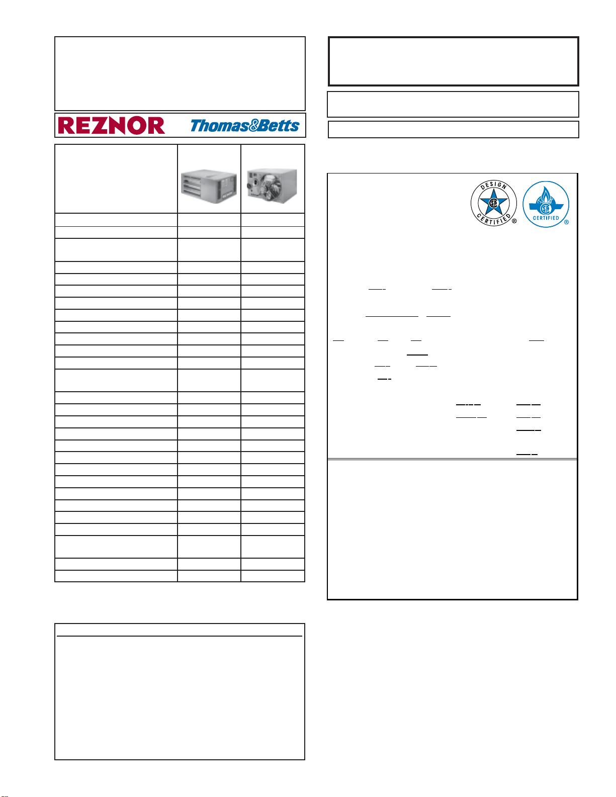
Model FT and Model SFT
Unit Heaters
INST ALLATION FORM RZ-NA -P-FT/SFT
Obsoletes Form RZ-728
APPLIES TO: Replacement Parts
Index of Parts
Model FT Model SFT
by Page No.
Burner Rack 7 9
Cabinet Parts 6 10
Downturn Air Outlet Nozzles 14 14
(same as Options CD 2, 3, 4)
Electrical Components 2-5 8-9
Fan and Components 7 10
Fan Guard 7 10
Gas Conversion Kits 12 12
Heat Exchangers 7 11
Ignition Control Board 4-5 8
Ignitor 4-5 8
Limit Control 4-5 8
Louvers, Horizontal 6 10
Louvers, Vertical (same as 13 13
Option CD1)
Manifold 7 9
Motor, Fan 7 10
Motor, Venter 2-5 8
Orifices, Burner 12 12
Rating Plate 1 1
Serial Number 2 2
Switch, Flame Rollout 4 9
Switch, Pressure 4-5 9
Thermostat 15 15
Transformer 4-5 9
Valve 4-5 8
Vent Cap (same as Option CC1) 7 -Vent/Combustion Air Kits (same -- 11
as Option CC2 and CC6)
Vent Tape (same as Option FA1) 15 15
Venter Parts 2-5 8
Additional References (use Form RZ designation to
order literature; not the P/N)
Description/Application................................... Form RZ ....... P/N
Parts/Service - Replacement Gas Valves and
Ignition Control Boards by Serial No. Code. P-VALVES .......N/A
Service - Converting to Other Gases ............ FT/SFT-GC ..148066
Installation/Operation - Model FT Heaters .............. I-FT ..173473
Installation/Operation - Special Model
FT-CV or FT-LN Unit Heaters ................. I-FT-CV/LN ..177854
Installation/Operation - Model SFT Heaters .......... I-SFT ..173474
Installation Instructions - Optional
Vertical Louvers, Models FT and SFT ..... I-FT/SFT-VL..160807
Installation Instructions - Optional
Downturn Nozzle, Models FT and SFT. I-FT/SFT-DN..160808
Rating Plate and Serial No.
Example of a Rating Plate
REZNOR
MERCER, P A. USA 1 613 7
MADE IN USA
UNIT HEATER
CATEGORY
ANSI Z83.8 [ A ] CG A 2.6- M [ A' ] UNIT HEATER
CSA .10.96 U. S. (2nd Ed.) UNIT HEATERS FOR RESIDENTIAL INSTALLATION
MODEL [ B ] [ C ]
SERIAL NO .
[ D ] VOLTS [ D ] PH [ D ] H Z MAXIMUM TOTAL INPUT [ D ] AMPS
TYPE OF GAS: [ E ]
FOR USE AT [ F ] FEET [ G ] METERS O F ALTI TUDE.
ORIFICE SIZE [
NORMAL I NPU T
THERM AL OUTPUT CA P A CITY
NORMAL MANIF O L D PRE S S URE
MIN. PERM ISSIBLE GAS SU PPLY PRESSURE
FOR PURPO S E OF INPUT ADJUST ME N T .
CLE ARANCES TO CO MBU S T I BLE CONS TRUCTI O N: TOP-1 ", FL UE
CONNE CTION-6 ", CO NTRO L S I DE - 1 8 ", OPP. SIDE-1 ", BOTTO M-1"
FOR ALTERNATE INSTALLATIONS USE THE LA TEST EDITIONS OF THE
APPROPRIATE STAND AR D LI STED BELOW:
FOR AI R CRAFT HANGARS U S E STANDARD ANSI /NFPA 409
FOR PARKI NG S TRUCTU RE S U S E S TANDARD ANSI/NFPA 88A
FOR RE PAI R GARAGE S U S E STANDARD ANSI/NF PA 88B
THIS UNIT IS NOT FOR USE WITH DUCTS.
THIS UNIT IS NOT FOR USE WITH FILTERS.
CONSTRUCTION WALL THICKNES S FOR PU RPOSE O F V E NTING:
1" M IN., 30" MAX.
Rating Plate Key:
A = Date of ANSI Standard
1
= Date of CGA Standard
A
B = Model No.
C = Month and Year of
Manufacture
D = 115V, 1 Phase, 60 Hertz,
Maximum Total Input Amps
E = Natural or Propane Gas
F/G = Elevation (Feet/Meters)
H = Orifice Size
I = BTU Input Sea Level
III
H ] DRIL L HAS BEEN F ACTORY ADJUSTED
SEA LEVEL ALT. ADJUSTED
[
I ] [ J ]BTU/HR.
[
K ] [ L ]BTU/HR.
[
[
J = BTU Input Altitude Adjusted
K = BTU Thermal Output Sea
Level
L = BTU Thermal Output
Altitude Adjusted
O = Manifold Pressure (3.5 w.c.
Natural Gas; 10 w.c.
Propane Gas)
P = Minimum Gas supply
Pressure (5.0 w.c. Natural
Gas; 11.0 w.c. Propane Gas)
Form RZ-NA-P-FT/SFT, Page 1
O ] IN.W.C.
P ] IN.W.C.
Page 2
Rating Plate and Serial No. (cont'd)
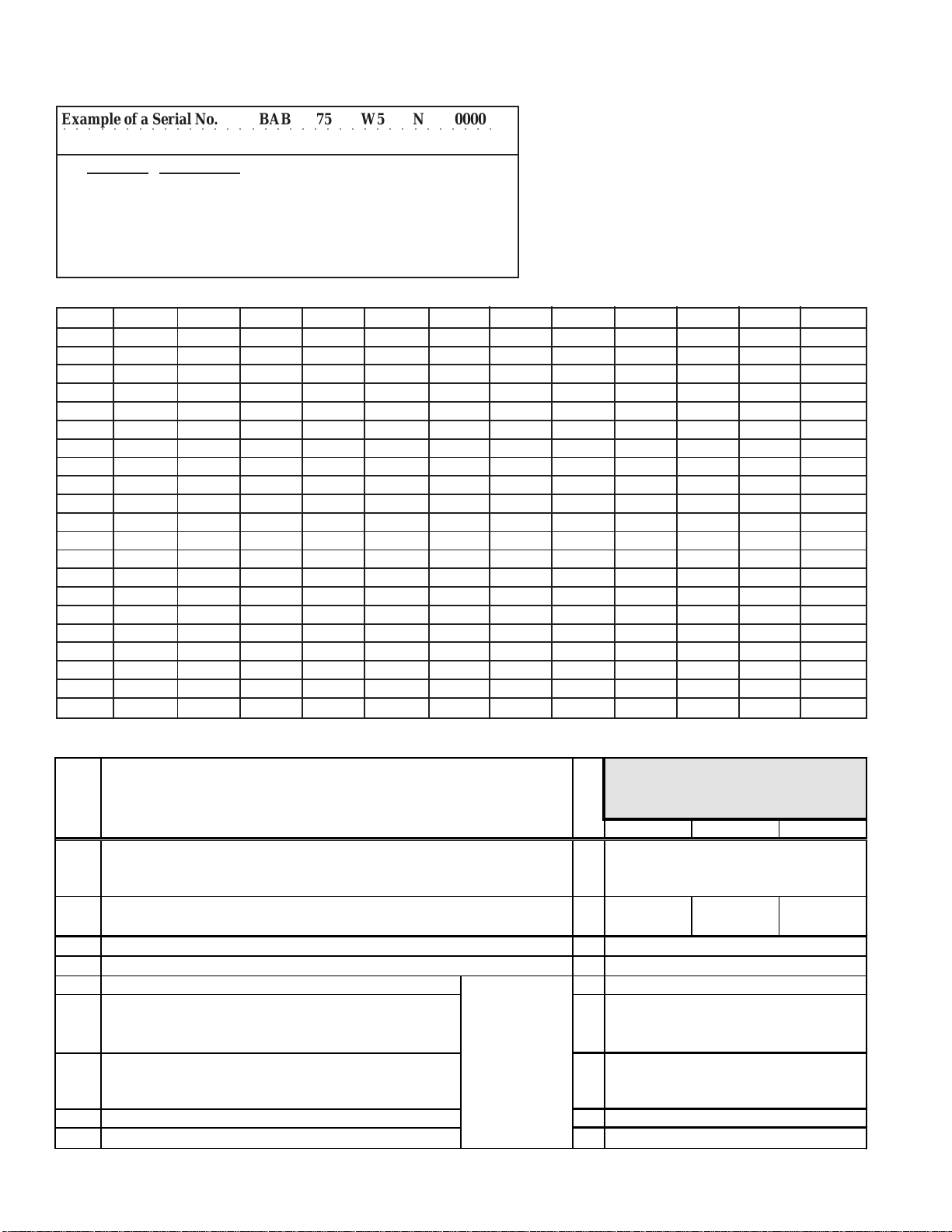
Decoding a Serial No.
Example of a Serial No. BAB 75 W5 N 00000
○○○○○○○○○○○○○○○○○○○○○○○○○○○○○○○○○○○
Code Nos. 1234 5
Code No. Explanation
1 Date of manufacture (see below)
2 Type of pilot system (see Form RZ 714)
3 Type of gas valve (see Form RZ 714)
4 Gas (N = natural; L = propane)
5 Consecutive number (identification only)
First Element of the Serial Number - Date of Manufacture
Year Jan Feb Mar Apr May June July Aug Sept Oct Nov Dec
1995 AUA AUB AUC AUD AUE AUF AUG AUH AUI AUJ AUK AUL
1996 AVA AVB AV C AVD AVE AVF AVG AVH AV I AVJ AV K AVL
1997 AWA AWB AWC AWD AWE AWF AWG AWH AWI AWJ AWK AWL
1998 AXA AXB AXC AXD AXE AXF AXG AXH AXI AXJ AXK AXL
1999 AYA AYB AYC AYD AYE AYF AYG AYH AYI AYJ AYK AYL
2000 AZA AZB AZC AZD AZE AZF AZG AZH AZI AZJ AZK AZL
2001 BAA BAB BAC BAD BAE BAF BAG BAH BAI BAJ BAK BAL
2002 BBA BBB BBC BBD BBE BBF BBG BBH BBI BBJ BBK BBL
2003 BCA BCB BCC BCD BCE BCF BCG BCH BCI BCJ BCK BCL
2004 BDA BDB BDC BDD BDE BDF BDG BDH BDI BDJ BDK BDL
2005 BEA BEB BEC BED BEE BEF BEG BEH BEI BEJ BEK BEL
2006 BFA BFB BFC BFD BFE BFF BFG BFH BFI BFJ BFK BFL
2007 BGA BGB BGC BGD BGE BGF BGG BGH BGI BGJ BGK BGL
2008 BHA BHB BHC BHD BHE BHF BHG BHH BHI BHJ BHK BHL
2009 BIA BIB BIC BID BIE BIF BIG BIH BII BIJ BIK BIL
2010 BJA BJB BJC BJD BJE BJF BJG BJH BJI BJJ BJK BJL
2011 BKA BKB BKC BKD BKE BKF BKG BKH BKI BKJ BKK BKL
2012 BLA BLB BLC BLD BLE BLF BLG BLH BLI BLJ BLK BLL
2013 BMA BMB BMC BMD BME BMF BMG BMH BMI BMJ BMK BML
2014 BNA BNB BNC BND BNE BNF BNG BNH BNI BNJ BNK BNL
2015 BOA BOB BOC BOD BOE BOF BOG BOH BOI BOJ BOK BOL
Model FT Control Compartment and Electrical Components
Qty
Code
1A
Vent er Housing Assy - standard heater (does not apply to Model FT with suffix CV
or LN ; see Code 1B)
Vent er Housing Assy - Size 30 or 45 heater with suffix CV (Option AV6) or LN
1B
(Option AL2B)
Venter Gasket (not illustrated)
2
Static Pressur e Tap
3
Venter Motor & Wheel Assy (includes Codes 4A-4D) 1
*4
Vent er M otor 1
*4A
(**Sizes 150-200 is an assembly including motor, P/N 148053;
capacitor, P/N 1638 94; and capacitor boot, P/N 103182)
Venter Wheel 1
*4B
Vent er M otor Plate 1
*4C
Venter Fan Blade 1
*4D
*11/97 is Serial No. Date Code AWK; but always verify actual type of approval stated on the rating plate.
Form RZ-NA-P-FT/SFT, Page 2
Description
Apply to standard
Model FT (go to
page 5, Codes 5
and 6, for venter
parts for special
Model FT-CV or
FT-LN)
For heaters mfgd
approval (approx. 11/97*- verify on rating
1
1------
1
1
PRIOR TO
plate)
30 45 60
147357
147793
116043
147359
97738
Magnetek #JA1M156N
135979
Revcor B506-1005
135981
68005
residential
Page 3
Model FT
-
)
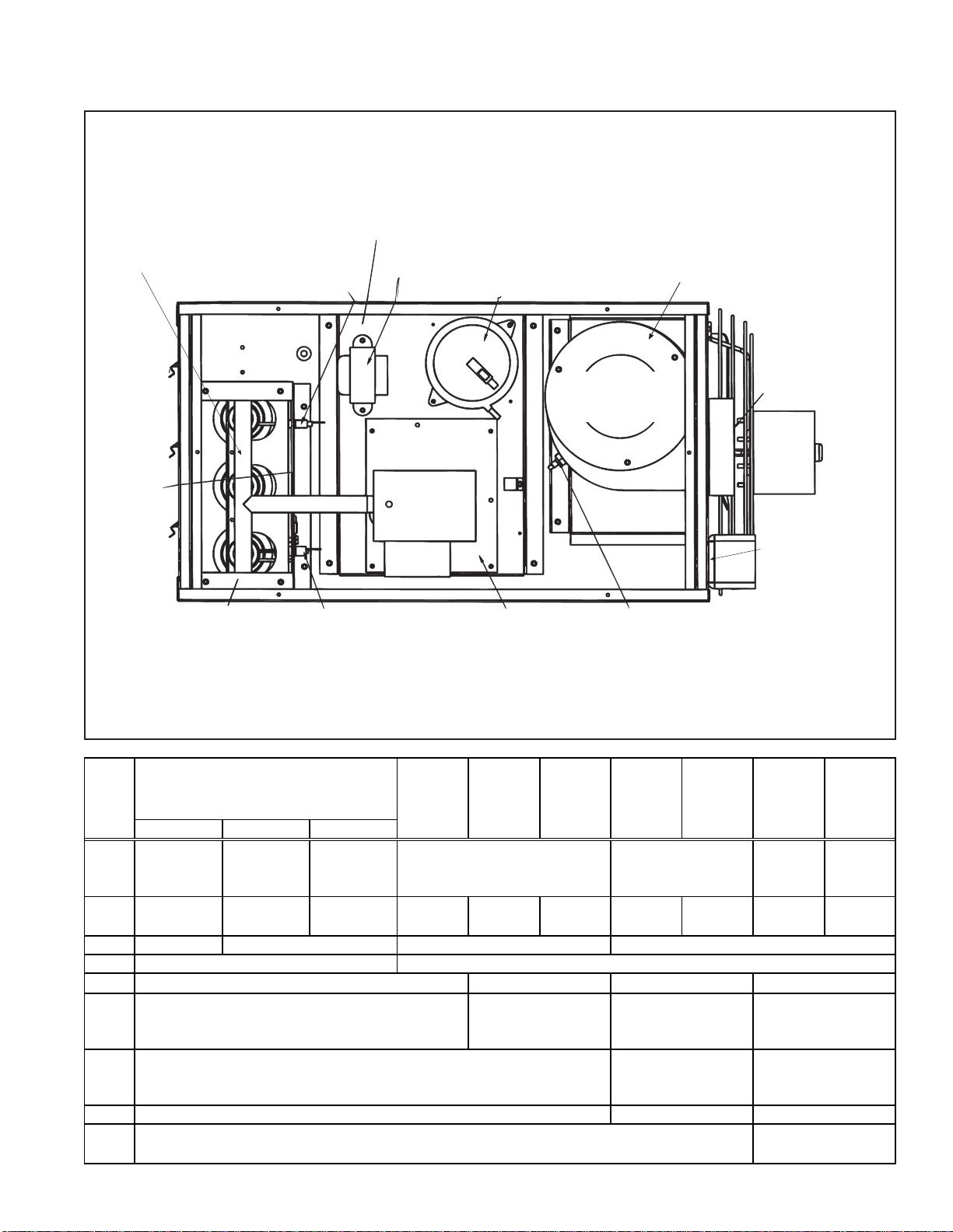
Control Compartment and Electrical Components - see P/N listings, pages 2-5
Model FT Control Compartment (A Size 30 is illustrated; locations are approximately the same for
other sizes but may appear out of proportion.)
11 - Limit Control Sizes 30-75 (Located
in the heat exchanger
compartment; remove
louvers to access.)
8 - Flame Sensor
11 - Lmit Control - Sizes 100-300
12 - Transformer
14 Pressure Switch
1 - Venter Housing
4, 5, 6 -
Venter Motor
Flue Outlet
& Wheel Assy
18 Fan
Motor
17 -
Flame
Rollout
10 - Gas
Valve
Switch -
Sizes
30-60
16 - Auxiliary
Limit - Sizes
250-300 only
(remove fan
Burner/Manifold
Assembly
9 - Spark
Electrode
with Ignition
13 - Circuit Board
(Ignition Module)
3 - Static
Pressure Tap
guard to access)
Cable
NOTE: If the heater has been changed so that the controls are on the left side, their locations will appear inverted. On Sizes 60-300,
the ignitor must still be toward the bottom of the heater with the flame sensor toward the top.
Code
1A
1B
For heaters
beginning approx 11/97* - verify on rating
30 45 60
164689
(replaces
158435)
176809 176309 -- -- -- -- -- -- -- --
residential app roval (mfgd
WITH
plate
164690
(replaces
158436)
164691
(replaces
158448)
147357
147657
200
250 30075 100 125 150
149164 149165
2
3
*4
*4A
*4B
*4C
*4D
147793
P/N 116043 is p art of Vntr Housing, Code 1A
Magnetek #JA1M213N (replaces P/N 97738, Magnet ek
continued on the next page
#JA1M156N)
Revcor B506-1005 Brookside #FE-400- 200
14779344695
116043
148056
Magnetek #JA1M213N Includes P/N 148053,
135979 97724
135981
68005
148057
**148980148055 148055
Magnetek #JE1E024N
2
97301 164380
97300
149160147359
150771
Magnetek #JE1F022
135980
Brookside #FE610-200-
1
141570 (replaces 68005
on 250/300)
Form RZ-NA-P-FT/SFT, Page 3
Page 4
Model FT Electrical Components (cont'd) - Refer to the illustration on page 3
)
P
Fo r heaters mfgd
residential approv al (approx.
Code
5
Venter Mtr & Wheel Assy (includes Codes 5A-5G) - Size
30 or 45 heater with suffix CV (O ption AV6) only
Vent er Motor 1 -- -- -- --
5A
Venter Wheel 1 -- -- -- --
5B
Venter Motor Plate 1 -- -- -- --
5C
Vent er Motor Plate Gasket 1 -- -- -- --
5D
Secondary M otor Plat e 1 -- -- -- --
5E
Spacers 4 -- -- -- --
5F
Venter Fan Blade 1 -- -- -- --
5G
Vntr Mtr & Wheel Assy (includes Codes 6A-6G) - Size 45
6
heater with suffix LN (Option AL 2B) only
Venter Motor 1 -- -- -- -- 175987 --
6A
Venter Wheel 1 -- -- -- -- 135979 --
6B
Vent er Motor Plate 1 -- -- -- -- 176311 --
6C
Vent er Motor Plate Gasket 1 -- -- -- -- 155651 --
6D
Isolator, rubbe r w/brass insert 4 -- -- -- -- 113498 --
6E
Isolator Plate 1 -- -- -- 176310 --
6F
Venter Fan Blade 1 -- -- -- -- 68005 --
6G
Vntr Inlet Ring - Size 45 with suffix CV or LN only
7
Flame Sensor, Channel Products #1259-85 1
8
Sp ark Ignitor with Cable - applies only to heaters with
9A
Johnson Controls G861 Ignition Control Board, P/N 174260
(Code 13)
Spark Ignitor 1
9B
Ignition Cable 1
Gas Valve Natural 1
10
Identify the valve on the
NOTE:
heater by manuf acturer's no. and the
Serial No. code on page 2.
Limit Control, Thermodisc #36T 1
11
(access by removing louvers)
Transformer, 30 VA, #4000-01M04BB80 1
12
Ignition Contr ol Board , J/C G861 1
13
Pressure Switch - applies to
14A
standard heater (for Size 30 or 45
with suffix CV or LN, see Code 14B
Pressure Switch - applies to Sizes
14B
30 and 45 with Suffix CV or LN only
Silicone Rubber Tubing for Pressure 1 147905 147905
15
Sensing (not illustrated) 7 " long 9" lg 7 " lon g 9" long
Au xiliary Limit Control (remove fan guard to acces s) 1 -- -- -- -- -- --
16
Flame Rollout Switch (manual reset) Std FT & suffix CV 1 -- -- -- 121275, 275°F 112752, 225°F 121275, 275°F
17
Fan Moto r - See Code 39C for standard Model FT or Model FT with suffix CV; see Code 40C for Model FT with suffix LN
18
Outlet Box , 2x4, Steel City #58361 1 -- -- 17782 -- -- --
19
Outlet Box Cover 1 -- -- 17 800 -- -- --
20
Form RZ-NA-P-FT/SFT, Page 4
Description (cont'd)
Apply to Model FT
with s uffix CV
(Option AV6)
Apply to Model FT
with s uffix LN
(Option AL2B)
use w/RAM 3MC4
ignition cntrl board
Propane 1
up to 4000 ft 1 164672
4001-9000 ft 164674
up to 4000 ft 1 -- -- -- --
4001-9000 ft -- -- -- --
Model FT45-LN only -- -- -- -- 121275, 275°F --
Qty
11/97*- ver ify on rating plate)
30 45 60 30 45 60
1-- -- -- --
1 -- -- -- -- 176329 --
1-- -- -- -- 62594 --
1
172552, M/H VR8105M2187
Gas
Gas
(replaces 147133, Robertshaw #7222 DER; field-supplied pip ing is r equired)
172553, M/H VR8105M2825
(replaces 147134 , Rober ts haw #7222 DERLP; field- supplied piping is required)
174260 (replaces P/N 147102 and may be used with either Code 9 A or 9B; if
TDI #PPS10027-2228
TDI #PPS10027-2355
147904 147904
RIOR TO
147165
159956 (assembly replaces both 147166 and 14 7167)
147166
147167
45602
180°F
147356
replacing board and ignitor, order Code 9A)
148072
149879
Fo r heaters
approx. 11/97* - verify on rating plate)
Magnetek #JA2N297
Revc o r B5 06 -1005
TDI #PPS10027-
2731 (replaces
159180)
TDI #PPS10027-
2733 (replaces
159181
TD I #PPS10027-2731
TD I #PPS10027-2733
residential approv al (beginning
WITH
177148
175987
135979
176311
155651
176810
98872
68005
Magnetek
#JA2N297
Revcor B506-
1005
147165
147166
147167
172552, M/H VR8105M2187
172553, M/H VR8105M2825
45602
180°F
147356
164673, TDI #PPS10027-2732
(replaces
148072)
164675, TDI #PPS10 027-2734
(replaces
148072)
164672
164674
(replaces
149879)
(replaces
159179)
Page 5
Code
75 100 125 150 200 250 300
5A
5B
5C
5D
5E
5F
5G
6A
6B
6C
6D
6E
6F
6G
9A
5
-- -- -- -- -- -- --
-- -- -- -- -- -- --
-- -- -- -- -- -- --
-- -- -- -- -- -- --
-- -- -- -- -- -- --
-- -- -- -- -- -- --
-- -- -- -- -- -- --
-- -- -- -- -- -- --
6
-- -- -- -- -- -- --
-- -- -- -- -- -- --
-- -- -- -- -- -- --
-- -- -- -- -- -- --
-- -- -- -- -- -- --
-- -- -- -- -- -- --
-- -- -- -- -- -- --
-- -- -- -- -- -- --
7
8
159 956 (assembly replaces both 147166 and 147167)
-- -- -- -- -- -- -147165
159957 (assembly replaces both 147166
and 148085)
9B
147167
10
172552, M/H VR8105M2187
(replaces 147133, Robertshaw #7222 DER; field-supplied piping is required) M/H #VR8305- M 4009
172553, M/H VR8105M2825
(replaces 147134, Robertshaw #7222 DERLP; field-s upplied piping is required) M/H #VR8305M 4017
11
45602
147166
147830 150839
M/H #VR8205M1130
147560
M/H #VR8205M1148
155764 (r ep laces 96512)
148085
155 765 (r ep laces (85449)
180°F 220°F, Blue Dot 200°F, Yellow Dot
12
13
14A
174260 (replaces P/N 147102 and may be used w i th either Code 9A or 9B; if repl acing board and ignitor, order Code 9A)
148072 150837
147356
TDI #PPS10027-2228 TDI # PPS10027-2392
149879 151372
14B
TDI #PPS10027-2355
-- -- -- -- -- -- --
TDI # PPS10027-2406
-- -- -- -- -- -- --
15
147905
148251
9" long 12" long
16
17
-- -- -- -- --
-- -- -- -- -- -- --
100799, 150°F
150840
18
19
20
-- -- -- -- --
-- -- -- -- --
17782
17800
Form RZ-NA-P-FT/SFT, Page 5
Page 6

Model FT -
P
Cabinet and
Heat Exchanger
Parts
30A
Code
55
36
35
35
34
52
51
50
49
31
31
41
44
32
Location of
37
Code 16 on
Sizes 250 and 300
38 (Mount only;
does not include
fan guard)
Fan Sizes
150-300
39, 40
Fan Sizes
30-125
Vent
Cap
*Item 49 - Limit control location shown is for
33
30B
Sizes 100-300. On Sizes 30-75, the limit control
is located between the first and second heat
exchanger tube and is accessible from the heat
exchanger compartment.
For heaters mfgd
residential approval
C
Descri ption
o
d
e
Top Outer Mfgd after 3/99 1 147225
30A
Panel Mfgd before 3/99 1 175833
Bottom Outer Mfgd after 3/99 1 147226
30B
Panel Mfgd before 3/99 1 175834
Top/Bot tom Retainer Panel 2 147223 -- --
31A
Small Top/Btm Retainer Panel 2 -- -- -- -- -- -- -- -- -- -- --
31B
Large Top/Btm Retainer Panel 2 -- -- -- -- -- -- -- -- -- -- --
31C
Left Side Panel Assembly (Outer
32
Panel & Retainer)
Access Panel 1 147116 147116 147116
33
Right Front Mfgd after 3/99 1 -- -- -- 147113 147837 147114 147838
34
Panel M fgd before 3/99 1 175829 175830 175835 175829 175830 175835 175836
Top/Bot tom Front Panels 2 -- -- -- -- -- -- -- 147847 146476 147848 146477 150992 148682
35
Louver
36
Assembly
Fan Back M fgd after 3/99 1 -- 158734 147586
37
Mfgd before 3/99 1 175831 175831 175832
Fan Guard M ount Assembly
38
Form RZ-NA-P-FT/SFT, Page 6
TO
(approx. 11/97*- verify
Q
on rating plate)
t
y
30 45 60 30 45 60
147105
175827
147106
175828
147155
1 147575
147574
147115 147115 146490
1 147427 147850 131803
147426 147426 147427 94865
-- 147108
175826 175826
1-------- -- --------
RIOR
For heaters
residential approval (mfgd
beginning approx. 11/97* -
verify on rating plate)
147105
175827
147106
175828
147155
147574
WITH
147225
175833
147226
175834
147223 146615
75 100 125 150 200 250 300
146455
146455 148680
147816147575
146479
146492
148924
147158
147835 150990
148680
148591
148616
150977147817
148681146493
151595
148685
Page 7

C
o
d
e
39
39A
39B
39C
40
40A
40B
40C
41A
41B
42
43
44
45
46
47
49
50
51
51A
51B
51C
52
53
54
55
Description
(includes Codes 39A-39C) -
applies to standard Model FT
and Model FT with CV suffix
(for heater with LN suffix, see
Code 40)
Fan Guard 1 151992
Fan Blade - applies to
standard FT or Model Ft with
CV suffix (for heater with LN
suffix, see Code 40B)
Fan Motor - applies to
standard FT or Model Ft with
CV suffix (for heater with LN
suffix, see Code 40C)
Fan, Fan Guard, and Mt r
Assy (includes Codes 40A40C) - applies to Model FT
with LN suffix only
Fan Guard 1 -- -- -- -- 151991 -- -- -- -- -- -- -- -Fan Blade - applies to Model
FT with LN suffix only
Fan Motor - applies to Model
FT with LN suffix only
Flue Wrapper Assy -
standard Model FT and
Model FT with suffix LN (for
Size 30 and 45 with CV suffix,
see 41B)
Flue Wrapper Assy - applies
to heaters with CV suffix only
Top/Btm Flue Gasket 2 147395
Side Flue Gasket 2 147227 147228 147229 147227 147228 147882 147652 147855 147653 147855 147653
Heat Ex changer/Turbulator/
Inner Panel Assy
Mid-Tube
Support (heat
exchanger)
Mid-Tube
Support Bracket
Tube Clamp 1 -- -- -- -- -- -- -- -- -- -- -Limit Control Bracket 1 -- -- -- -- -- -- -- -Burner Box 1 147057 147058 147063 158441 158424 158425 147064
Burner Rack Assy (includes
51A, 51B, and 51C)
Burner
Not
illustrated see SFT
illustration
on page 10.
Burner Support Slot 1 147566 147567 147568 147566 147567 147568 147569
Burner Clamp 1 150184 105185 150153 150184 105185 150153 149595
Manifold (less orifices) 1 147003 147004 147136 147003 156094 156095 156096 151785 151786 151787 151788 151787 151788
Burner Orifices - See Table on page 12.
Hanger Angle Sub-Assembly2-- -- -- -- -- -----------Vent Cap (S ame as Option
CC1)
For heaters mfgd PRIOR TO
residential approval (approx.
Q
11/97*- verify on r ating plate)
t
y
30 45 60 30 45 60
1 147181 147182 147183 147181 147182
151991 (replaces
147185
1 125566
Revcor #01005-34
1 147103 147104 150332 147103 147104
Magnetek
1 -- -- -- -- 176490 -- -- -- -- -- -- -- --
1 -- -- -- -- 129853,
1 -- -- -- -- 175988,
1 147444 147445 147446 158433 158434 158442 147447 147911 147649 147880 147650 150995 150996
1 -- -- -- 176817 158434 -- -- -- -- -- -- -- --
1 148067 148068 148069 148067 148068 148069 148070 157939 157940 157941 157942 157943 157944
1-- -- -- -- -- ------------
2------------------
1 147577 147578 147579 147577 147578 147579 147580 147822 147823 147824 147825 150783 150784
Qty > (2) (3) (4) (2) (3) (4) (5) (5) (6) (8) (10) (8) (10)
1 111850
Magnetek
#JA2N
#JA2R
147394 147394 147395 147651
147132
Beckett #X783
111848 111848 111849
(rep laces
147157)
F07H07
15.75-31
1/20HP
(rep laces
4" diameter
For heaters WITH residential
approval (mfgd beginning
approx. 11/97* - verify on
151991 (replaces
147185
129853 125566
Lau
Revcor #01005-34 Lau #610257-01 Revcor T2004-33Lau Y10S08A
Magnetek
Smith
#F42A
53A13,
95547)
#JA2N
rating plate)
Magnetek
#JA2R
#01005-
34
Magnetek
2E3C002
75 100 125 150 200 250 300
147183 147672 147673Fan, Fan Guard & Mtr Assy
151992
(replaces
147157)
Lau F07H07
15.75-31
150332 147908
A. O. Smith
#F42A53A13,
1/20HP
(replaces 95547)
-- -- -- -- -- -- -- --
-- -- -- -- -- -- -- --
147230
147221
Beckett #X783
136949, 18"
round (replaces
45616)
141598129853
A. O. Smith
#F42C81A13,
1/6HP
146473 146474
147132 150836
104818, 20" square, flat
150155 150838
147913
A. O. Smi th
#F48H01A13,
1/4HP
155264
HE4T005, 1/2HP
148619
Beckett #10924X
146482 146484
146481 146483
4" diameter 5" diameter 6" dia
* 11/97 is Serial No. Date Code AWK (see page 1); but always verify actual typ e of approval stated on the rating plate before selecting replacement parts.
150997
2436
156275
Magnetek
(rep laces
100589)
148618
148684
150991
Form RZ-NA-P-FT/SFT, Page 7
Page 8

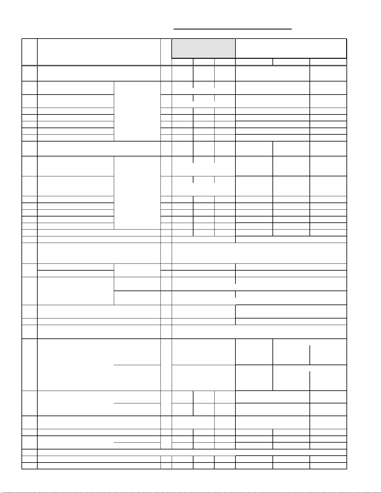
Model SFT - Electrical and Burner Box Components
Control
Compartment Model SFT
68 - Limit Control - Sizes
100-300 (located in heat
exchanger compartment)
65 -Flame Sensor
Combustion Air Collar
(flex hose removed for clarity)
72 Transformer
70 - Pressure
Switch
60 - Venter Housing/
63 - Venter Motor and
Wheel Assembly
Venter Outlet
(Flue) Collar
71 - Flame Rollout
Switch - Sizes 45-75
(located on the burner
box cover behind
the collar; disconnect
hose to access)
74 Fan
68 - Limit Control
Location - Sizes 45-75
(located in heat
67 - Gas
Valve
Motor
exchanger compartment;
remove louvers to access)
Burner/Manifold
Assembly (see page 9)
66 - Ignitor
Code Qty 45 60 75 100 125 150 200 250 300
Venter Housing Assembly 1 156854 156856 157289
60
Venter Gasket (not illustrated) 1 147793
61
Flow Sensing Probe Assy (not illustrated) 1
62
Venter Motor & Wheel Assy (includes Codes 1 156472
63
63A-63H) Venter Motor 1
63A
Capacitor, 4MFD @ 370V 1 - - - -
63B
Capacitor Boot 1 - - - -
63C
Venter Wheel 1 135979
63D
Venter M otor Plate
63E
Venter Fan Blade 1
63F
Spiral Spacer 4
63G
Nut #8- 3 2 4
63H
Venter Motor Plate Gasket 1 155651
64
Flame Sensor - Channel #1259-85 1
65
Spark Ignitor with Cable - applies only to heaters
66A
with Johnson Controls G861 Ignition Control
Board, P/N 174260 (Code 69)
Spark Ignitor 1
66B
Ignition Cable 1
Gas Valve Natural Gas 1
67
NOTE: Identify the valve on the
heater by the manufacturer's no. and
the Serial No. code on page 1.
Limit Control & Bracket Assy (includes 68A) 1
68
Snap Disk Limit Control 1
68A
Ig nition Control Board, J/C G861 1
69
Form RZ-NA-P-FT/SFT, Page 8
Description
Code 64 required with 63)
(Code 64 required with 63E)
RAM 3MC4
control board
Revcor
B506-
1 135981
1
use with
ignition
(repla ces 147133, Robertshaw #7222DER; field-
Propane Gas 1
(repla ces 147134, Robertshaw #7222DERLP;
174260 (replaces P/N 147102 and may be used with either Code 66A or 66B; if replacing
69 - Ignition
Control Module
148980 150771
Includes motor P/N 148053, Magnetek
#JE1E024N, and Codes 63B & 63C
163894
103182
Brookside #FE610-119-1
68005, 2.25" dia, 5/16" bore 141570, 2.25" dia., 3/8" bore
97722 - #8 x 15/16" long 97721 - #8 x 3/4" l ong
159956 (assembly replaces both 147166 and
147167)
147167 148085
172552, M/H
#VR8105M2187
supplied piping is required)
172553, M/H
#VR8105M2825
field-sup plied piping is required)
155985 147670 151516
45602 - 180°F 155764 - 220°F 155765 - 200°F
TOD 60T11-201614 TOD 36TV21-13878
73 Terminal
Block
156855 156857
155650 155649
155980 155981
155271 135980
147830, M/H
#VR8205M1130
147560, M/H
#VR8205M1148
board and ignitor, order Code 66A)
Flow Sensor (for
tubing connection
to the pressure switch)
148978
Magnetek #JE1F022N
Brookside #FE610-200-3
151515
31522
155652
147165
159957 (assembly replaces both 147166
147166
147830, M/H
#VR8205M1130
147560, M/H
#VR8205M1148
Inlet
Collar
and 148085)
150839, M/H
#VR8305M4009
150840, M/H
#VR8305M4017
TOD 36TV21-13879
Page 9

Code Qty 45 60 75 100 125 150 200 25 0 300
)
(rep
)
)
Pressure Switch, T DI #FS6210A 1
70A
High Altitude Pressure Switch (above 4000 ft) 1
70B
71
Flame Rollout Swit ch, T OD #36T26-662, 180
Transformer, 30VA, Products 4000-01-M04BB80 1
72
Terminal Board , Dor an 1
73
Fan Motor - See Code 113C
74
T u bing from pressu re switch to pressure tap 1
75
Tubing from pressure switch to probe 1 133117 - 11" 155377 - 15"
76
Description
173312, -0.60 w.c. (replaces
173316, -0.55 w.c. (r ep laces
o
1 - - ----
F
156302
157278)
157282
174399 - 13" 151564 - 17"
173311, -0.40 w.c.
laces 1563 01
173315, -0.35 w.c.
(replaces 157277 )
147356
151600
173313, -0.65 w.c. (replaces
156303
173312, -0.60 w.c. (replaces
156302)
Burner Box
Components -
87 - Burner Rack Assembly
Model SFT
To remove the burner rack/manifold
assembly, lift up and then pull out.
1/4-20
Hex Nut
Gas
Valve
80 - Burner
Box Cover
86 - Static
Pressure Tap
84 -
Manifold
Cover
Plate
Locating
Burner Box
Assembly
Pins (hidden)
85 - Manifold
Seal Plate
Code Description Qty 45 60 75 100 125 150 200 250 300
Burner Box Cover Assy (includes flue col lar) 1 157286 157287 157288
80
Neoprene Gas kets Side 1 155607 155606 156605
81
inside Burner Box T op/Bt m 2
82
(not illustrated) Middle 1 155612 155611 155610
83
Manifold Cover Plate 1
84
Manifold Cover Plate Gasket (not illus trated) 1
84A
Manifo ld Seal Plate 1
85
Static Pressure Tap, TD #AA3743 (on Code 80) 1
86
Burner Rack Assy (located behind Code 80) 1 155851 155852 155853 155855 155856 160506 160507 155858 155859
87
155340 151828 155340
157008 157007 157008
156029 156030
155608 155609
155617 155618155615 155616
155613 155614
157162
116043
(Includes Codes 87A, 87B, 87C - not illustrated)
87A
Burner
Qty
(3) (4) (5) (5) (6) (8) (10) (8) (10)
→
147132 150836
Beckett #X783 Beckett #10924X
Burner S upport Slot 1 150187 150154 149596
87B
Burner Clamp 1 150185 150153 149595
87C
Igniter/F lame Sensor Cover with Viewports 1 156018 156019 156020 156011 156021 156022 156023 156024 156025
88
Manifold (less orifices) - behind Code 80 1 156094 156095 156096 151785 151786 151787 151788 151787 151788
89
Burner Orifices - See Table on page 10.
90
Fiberglass Gaskets for between Burner Box Sides 2 155619 155620 155621
91
146482 146484
146481 146483
155622 155623
& Heat Exchanger Assy Panel (not illustrated)
Fiberglass Gaskets fo r betwe en Burner Box Top & 2
92
155624 155625
Btm & Heat Exchanger Assy Panel (not illustrated)
Flexible Combustion Air Hose - 18" long 1 155408
93
155409 155410 155411
(not illustrated) 3" dia.
Worm Clamp s for Code 93 (not illustrated) 2 155319
94
120716 155320 155321
Form RZ-NA-P-FT/SFT, Page 9
156031
6" diameter4" diameter 5" diameter
Page 10

Model SFT Cabinet
and Heat Exchanger
Parts
106
105
100
107
Inner Panel/Heat
Exchanger Assy
102A
102B
102C
120
119
123
Heat Exchanger
Support/Hanger
Bracket Assembly
120
103
NOTES: The fan and motor
assembly is not exploded;
the fan guard mount (Code
112) is not part of the
assembly identified as Code
113. Turbulators (Code
118) slide into the heat
exchanger tubes as illustrated. The heat exchanger
support/hanger bracket
assembly is shown here as a
subassembly . Parts are
identified separately (Codes
119, 120, 123 and 102D).
102D
Burner
Box
Assembly
102A
104
114
Venter Motor and
Wheel Assembly
Code Qty 45 60 75 100 125 150 200 250 300
Top Outer Units mfgd beginning 10/00 1 147105
100
Panel Units mfgd prior to 10/00 1 155286
Bottom Outer Units mfgd beginning 10/00 1 1471 06
101
Panel Units mfgd prior to 10/00 1 155287
Top/Bottom Retainer Panel 2 147155 - -
102A
Large Top/Bottom Retainer Panel 2 - ------
102B
Small Top/Bottom Retainer Panel 2 - ------
102C
Bott om Support (Hanger) Angle 1 - - - - - - -
102D
Left Side Panel Assy (Outer Panel, Air
103
Deflector, and Retainer)
Access Panel Units mfgd beginn ing 10/00 1 1 47115
104
Hin ged Door
Assembly
Right Front Units mfgd beginning 10/00 1 147837 147114 147838
105
Panel Units mfgd prior to 10/00 1 155283
Top/Bottom Front Panel 2 - - - 147847 146476 147848 146477 150992 148682
106
Louver Units mfgd beginning 10/00 1
107
Assembly Units mfgd prior to 10/00 1
Fan Back Assy Units mfgd beginning 10/00 1 156246 156005 156006
108
(includes collar) Units mfgd prior to 10/00 1 178422 178430 178431
Fan Guard Mount Assem bly 1 - - - - -
112
Fan, Fan Guard & Mtr A ssy (113A-C) 1 147182
113
Fan Guard 1 151991, 10"
113A
Fan Blade 1 129853
113B
Form RZ-NA-P-FT/SFT, Page 10
Description
Units mfgd prior to 10/00,
Includes Latch,
P/N 156245
102B
101
1 157010
1 178422 178430 178431
147426 147850
Revcor #01005-
34
102C
108
112
147225
151832
147226 146455 148680
151833
147223
157011
147116
178423 178428 178429
151829
156082
147427
156247 156003 156004
178423 178428 178429
147183 147672 147673 150997
151992, 16" 136949, 18" 104818, 20" square, flat
125566 141598 150155 150838
Lau F07H07
15.75-31
157013 157014 150977
146490
146492
155095
131803
Lau #610257-01
Sizes
45-125
113
Sizes
150-300
146455 148680
151760 155128
155339155289
146615
148616
148591
148617
146479
146493 148681
151761 155275
94865
147835 157912
Revcor #T2004-33Lau Y10S08A
151595
2436
Page 11

Code Qty 45 60 75 100 125 150 200 250 300
Fan Motor 1 147104
113C
Flue Wrapper Assembly 1 156840 156841 156843 156845 156847 156849 156851 156852 156853
114
Top/Bottom Flue Wrapper
115
Gasket
Si de Flue Wrapper Gasket 2 147228 147229 147230 147882 147652 147855 147653 147855 147653
116
Heat Exchanger/Inner Panel Assembly 1 157936 157937 157938 157939 157940 157941 157942 157943 157944
117
Turbulators (Size 45, 60 & 75
118
turbulator are "square" assemblies) Qty
Mid-Tube Support (heat exchanger) 1 - - - - - - -
119
Mid-Tube Support Bracket 2 - - - - -
120
Tube Clamp 1 - 155388 155108 - - - -
121
Tube Clamp Bracket 2 - 155348 155101 - - - -
122
Hanger Angle Sub-Assem b ly 2 - - - - - - -
123
Description
(not
illustrated)
(not
illustrated)
150332 147908 147913
Magnetek
#JA2R
2 147394 147395 147395 147651 147651 147651 147651 147651 147651
(3) (4) (5) (5) (6) (8) (10) (8) (10)
>
A. O. Smith
#B42A53A13,
1/20HP
155090 146452
A. O. Smith
#F42C81A13,
1/6HP
A. O. Smith
#F48H01A13,
1/4HP
148619
155264
-
156275
1/2HP, Mag netek
HE45005
(replaces 100589)
148618
150991
Model SFT Separated-Combustion Venting and Combustion Air System Parts
Codes 130A
and 131A Concentric
Adapter Box
Assembly
Collar for
attaching the
combustion air
pipe from the
heater
Code 130B - Exhaust
T erminal (V er tical
Kit)
View of Heater Connection
Side
Opening for vent pipe
from the heater. Seal
with rubber gasket.
The vent pipe extends
through the box.
Code 130C -
Combustion Air
Inlet (V ertical
Kit)
(NOTE: Concentric adapter boxes manufactured prior to 2/01 had a collar on the "heater
connection side" to attach the vent pipe. There was a factory-installed length of vent pipe
through the box. If replacing a concentric adapter box manufactured prior to 2/01, the fieldsupplied vent pipe must be extended through the new box. Code 130E or 131F, rubber
gasket, is required to seal the opening around the vent pipe as it extends into the box.
View of Vent Terminal Connection Side
Collar for attaching the outside portion
of the combustion air pipe (the vent
pipe runs concentric through the
outside portion of the combustion air
pipe)
Code 131B - Screened
Exhaust Assembly
(Horizontal Kit)
Code 131C -
Inlet Guard
(Horizontal
Kit)
Code 130 - Vertical Vent Terminal/Combustion Air
Package (Option CC2) includes:
Code Qty SFT P/N Description
1 45-125
130
150-250
300
130A 1 45-125 155118
150-250 155392
300 68404
130B 1 45-250 155631, 4" Exhaust Terminal Cap
300 53326, 5"
130C 1 45-250 155635, 6" Combustion Air Inlet
300 53330, 8"
130D 1 45-300 53335 3 oz Tube of High
130E 1 45-250 164492, 4"
300 164493, 5"
157155
157156
54444
Comp lete Vertical Vent
Kit (Same as Option
CC2)
Concentric Adapter Box
Assembly
Temperature (450°F)
Silicone Sealant
Rubber Seal (blue) for
Exhaust Pipe
Code 131 - Horizontal Vent Terminal/Combustion Air
Package (Option CC6) includes:
Code Qty SFT P/N Description
131 1 45-125
150-250
300
131A 1 45-125 155118
150-250 155392
300 68404
131B 1 45-250 155096, 4"
300 53316, 5"
131C 1 45-250 151755, 6" Inlet Guard
300 124940, 8"
131D 4 45-300 376 61 #10-16 x 1/2" Screws (for
131E 1 45-300 53335 Tube of High Temperature
131F 1 45-250 164492, 4"
300 164493, 5"
157157
157158
82131
Complete Horizontal Vent
Kit (Same as Option CC6)
Concentric Adapter Box
Assembly
Screened Exhaust
Assembly
at tachin g inlet guard)
Silicone R ubber Sealant
Rubber Seal (blue) for
Exhaust Pipe
Form RZ-NA-P-FT/SFT, Page 11
Page 12

Burner Orifice Chart - Models FT and SFT
IMPORTANT NOTE: If the manifold pressure has been adjusted at the valve for high altitude operation, the standard sea level burner orifices
apply. The high altitude orifices in the table apply only to units purchased with a factory installed high altitude option. Check the rating plate to
determine at what altitude the unit was manufactured to operate.
Models FT an d SF T 30 45 60 75 100 125 150 200 250 300
BURNE R ORIFICES
Natural Gas, 0-2000 ft,
installed in U.S. or Canada Size
Propane Gas, 0-2000 ft,
installed in U.S. or Canada Size
Installed Natural 2001in Canada Gas 4500 Size
Propane ft
Gas Size
Installed Natural 2001in U.S. Gas 3000 Size
Propane ft
Gas Size
Natural 3001-
Gas 4000 Size
Propane ft
Gas Size
Natural 4001-
Gas 5000 Size
Propane ft
Gas Size
Natural 5001-
Gas 6000 Size
Propane ft
Gas Size
Natural 6001-
Gas 7000 Size
Propane ft
Gas Size
Natural 7001-
Gas 8000 Size
Propane ft
Gas Size
Natural 8001-
Gas 9000 Size
Propane ft
Gas Size
Quantity 234556810810
40414 40414 40414 40414 11833 11833 38678 11833 97362 97362
P/N
#48 #48 #48 #48 #4 4 #44 #45 # 44 #36 #36
63922 63922 63922 63922 11830 11830 64676 11830 96344 51284
P/N
1.15mm 1.15mm 1.15mm 1 .15mm #55 #55 1.3mm #55 1.65mm #52
39651 39651 39651 39651 38678 38678 84853 38678 45870 45870
P/N
#49 #49 #49 #49 #4 5 #45 #47 # 45 #38 #38
39659 39659 39659 39659 11830 11830 97359 11830 61653 9789
P/N
#58 #58 #58 #58 #5 5 #55 1.25mm #55 1.55mm #53
39651 39651 39651 39651 38678 38678 16590 38678 11835 11835
P/N
#49 #49 #49 #49 #4 5 #45 #46 # 45 #37 #37
63922 63922 63922 63922 11830 11830 97359 11830 51284 51284
P/N
1.15mm 1.15mm 1.15mm 1.15mm #55 #55 1.25mm #55 #52 #52
39651 39651 39651 39651 38678 38678 84853 38678 45870 45870
P/N
#49 #49 #49 #49 #4 5 #45 #47 # 45 #38 #38
63922 63922 63922 63922 11830 11830 97359 11830 61653 9789
P/N
1.15mm 1.15mm 1.15mm 1.15mm #55 # 55 1.25mm #55 1.55mm #53
39651 39651 39651 39651 38678 38678 84853 38678 45870 45870
P/N
#49 #49 #49 #49 #4 5 #45 #47 # 45 #38 #38
39659 39659 39659 39659 11830 11830 97359 11830 61653 9789
P/N
#58 #58 #58 #58 #5 5 #55 1.25mm #55 1.55mm #53
39652 39652 39652 39652 16590 16590 84853 16590 45871 45871
P/N
#50 #50 #50 #50 #4 6 #46 #47 # 46 #39 #39
39659 39659 39659 39659 39658 39658 63003 39658 9789 9789
P/N
#58 #58 #58 #58 #5 6 #56 1.2mm #56 #5 3 #53
39652 39652 39652 39652 84853 84853 40414 84853 87391 87391
P/N
#50 #50 #50 #50 #4 7 #47 #48 # 47 #40 #40
39659 39659 39659 39659 39658 39658 63003 39658 9789 9789
P/N
#58 #58 #58 #58 #5 6 #56 1.2mm #56 #5 3 #53
39652 39652 39652 39652 84853 84853 40414 84853 11792 11792
P/N
#50 #50 #50 #50 #4 7 #47 #48 # 47 #41 #41
95936 95936 95936 95936 39658 39658 63922 39658 9789 9789
P/N
#60 #60 #60 #60 #5 6 #56 1.15mm #56 #53 #53
39650 39650 39650 39650 40414 40414 39656 40414 11792 11792
P/N
#51 #51 #51 #51 #4 8 #48 #49 # 48 #41 #41
95936 95936 95936 95936 39658 39658 63922 39658 61652 11834
P/N
#60 #60 #60 #60 #5 6 #56 1.15mm #56 1.45mm #54
Gas Conversion Kits - Models FT and SFT
NOTE: Gas Conversion include standard burner orifices.
Model FT or SFT 30, 45, 60, 75 100, 125, 200 150 250 300
Natural to Propane Kit 179315 179317 179318 179327 179328
Propane to Natural Kit 179316 179319 179320 151180
Form RZ-NA-P-FT/SFT, Page 12
Page 13

Optional Vertical Louvers - Models FT and SFT
V ertical louvers are designed to direct the dischar ge air to provide a wider throw pattern. These vertical louver option packages apply to models and
sizes as listed in the table below.
The vertical louver option packages include:
Model FT and SFT FT SFT FT and SFT
Size 30 & 45 60 & 75 60 & 75 100 125 15 0 200 250 3 0 0
Option Package P/N 160850 160818 160819 160820 160821 160822 160823 160824 160825
Components: (Qty) P/N (Qty) P/N (Qty) P/N (Qty) P/N (Qty) P/N (Qty) P/N (Qty) P/N (Qty) P/N (Qty) P/N
Vertical Louver Top (2) 159443 (2) 159443 (2) 159443 (2) 159444 (2) 160889 (2) 160889 (2) 160889 (2) 160890 (2) 160890
/Bottom Member
Vertical Louver (4) 160500 (4) 160504 (4) 160501 (6) 160501 (6) 160502 (6) 160503 (6) 160505 (10) 160503 (10) 160505
#10-16 x 1/2" lg screw (32) 149563 (32) 149563 (32) 149563 (32) 149563 (32) 149563 (32) 149563 (32) 149563 (32) 149563 (32) 149563
Vertical Louvers
Top Member
Sheetmetal
Screws
Vertical Louver
(left side)
Bottom Member
Sheetmetal
Screws
Vertical Louver
(right side)
NOTE: Do not use vertical louvers above with downturn nozzle Option CD3 on
page 14; vertical louvers are included in downturn nozzle Option CD4.
Form RZ-NA-P-FT/SFT, Page 13
Page 14

Optional Downturn Nozzles for Models FT and SFT 75-300
Description:
Option CD2 is a downturn nozzle with a 25-65° variable air deflection range.
Option CD3 is a downturn nozzle with a 50-90° variable air deflection range.
Option CD4 is a downturn nozzle with a 25-65° variable air deflection range and vertical louvers (same as the vertical louvers on page 13)
Option packages include:
Model FT SFT FT and SFT
Size 75 75 100 125 150 200 250 300
Option CD2 Package P/N 160826 160827 160828 160829 160830 160831 160832 160833
Components: (Qty) P/N (Qty) P/N (Qty) P/N (Qty) P/N (Qty) P/N (Qty) P/N (Qty) P/N (Qty) P/N
Nozzle Side (2) 149578 (2) 159059 (2) 159063 (2) 159060 (2) 159067 (2)159065 (2) 159067 (2) 159065
Nozzle Top (1) 149580 (1) 149580 (1) 159062 (1) 159062 (1) 159066 (1) 159066 (1) 159068 (1) 159068
#10-16 x 1/2" lg screw (20) 149563 (20)149563 (20) 149563 (20) 149563 (20) 149563 (20) 149563 (20) 149563 (20) 149563
Option CD3 Package P/N 160834 160835 160836 160837 160838 160839 160840 160841
Components: (Qty) P/N (Qty) P/N (Qty) P/N (Qty) P/N (Qty) P/N (Qty) P/N (Qty) P/N (Qty) P/N
Nozzle Side (4) 149578 (4) 159059 (4) 159063 (4) 159060 (4) 159067 (4)159065 (4) 159067 (4) 159065
Nozzle Top (2) 149580 (2) 149580 (2) 159062 (2) 159062 (2) 159066 (2) 159066 (2) 159068 (2) 159068
#10-16 x 1/2" lg screw (34) 149563 (34)149563 (34) 149563 (34) 149563 (34) 149563 (34) 149563 (34) 149563 (34) 149563
Option CD4 Package P/N 160842 160843 160844 160845 160846 160847 160848 160849
Components: (Qty) P/N (Qty) P/N (Qty) P/N (Qty) P/N (Qty) P/N (Qty) P/N (Qty) P/N (Qty) P/N
Nozzle Side (2) 149578 (2) 159059 (2) 159063 (2) 159060 (2) 159067 (2)159065 (2) 159067 (2) 159065
Nozzle Top (1) 149580 (1) 149580 (1) 159062 (1) 159062 (1) 159066 (1) 159066 (1) 159068 (1) 159068
Vertical Louver Top/Bottom (2) 159443 (2) 159443 (2) 159444 (2) 159444 (2) 159444 (2) 159444 (2) 159445 (2) 159445
Member
Vertical Louver (4) 160504 (4) 160501 (6) 160501 (6) 160502 (6) 160503 (6) 160505 (10) 160503 (10) 160505
Nozzle Angle Clip (2) 149581 (2) 149581 (2) 159061 (2) 159061 (2) 159064 (2) 159064 (2) 159064 (2) 159064
#10-16 x 1/2" lg screw (44) 149563 (44)149563 (44) 149563 (44) 149563 (44) 149563 (44) 149563 (44) 149563 (44) 149563
Downturn Nozzle Parts
Nozzle Top,
CD 2, 3, 4
Nozzle Side,
CD 2, 3, 4
Nozzle Side,
Nozzle Side,
CD 2, 3, 4
Nozzle Side,
CD 3
Nozzle Top, CD 3
CD 3
Horizontal louvers (must be removed
from the heater and re-installed in the
outlet of the downturn nozzle.)
Form RZ-NA-P-FT/SFT, Page 14
Page 15

Miscellaneous - Models FT and SFT
P/N 91919, Thermostat,
1-stage, 24-volt, 40-80°F
(same as Option CL1)
P/N 91926, Locking Cover
for 1-stage thermostat
(same as Option CM1)
P/N 39581, Thermostat,
2-stage, 24-volt, 40-90°F
(same as Option CL3)
P/N 98266, High temperature
tape suitable for 550°F (for
vent pipe), 1" x 10 yards
(same as Option FA1)
Form RZ-NA-P-FT/SFT, Page 15
Page 16

Form RZ-NA-P-FT/SFT, Page 16
(800) 695-1901 ww w . Rez Spec.com
©2004 Thomas & Betts Corporation, All rights reserved. Printed in U.S.A.
MANUFACTURER OF GAS, OIL, ELECTRIC HEATING AND VENTILATING SYSTEMS
Trademark Note: Reznor® is registered in the United States and other countries.
804 OG POD Form RZ-NA-P-FT/SFT
 Loading...