

Page 1
Form I-OIL-HS (Version A)
Obsoletes Form I-OIL-HS
Installation Instructions for Oil Tank
Heater Stand, Option ST1
Applies to: Oil-Fired Heater Models OH 95, 140, 190;
RA 110, 140, 150, 235, 250; RV 225, 325
and a Model OT-250 Oil Tank
Description/
Application
IMPORTANT
The Option ST1 heater
stand may only be used
with a Reznor® Model
OT-250 workbench oil
tank and one of the
Reznor heaters listed
below.
Model ......Sizes
OH ...........95, 140, 190
RA ...........110, 140, 150, 235, 250
RV ...........225, 325
DO NOT use this
heater stand with any
other models or sizes of
heaters.
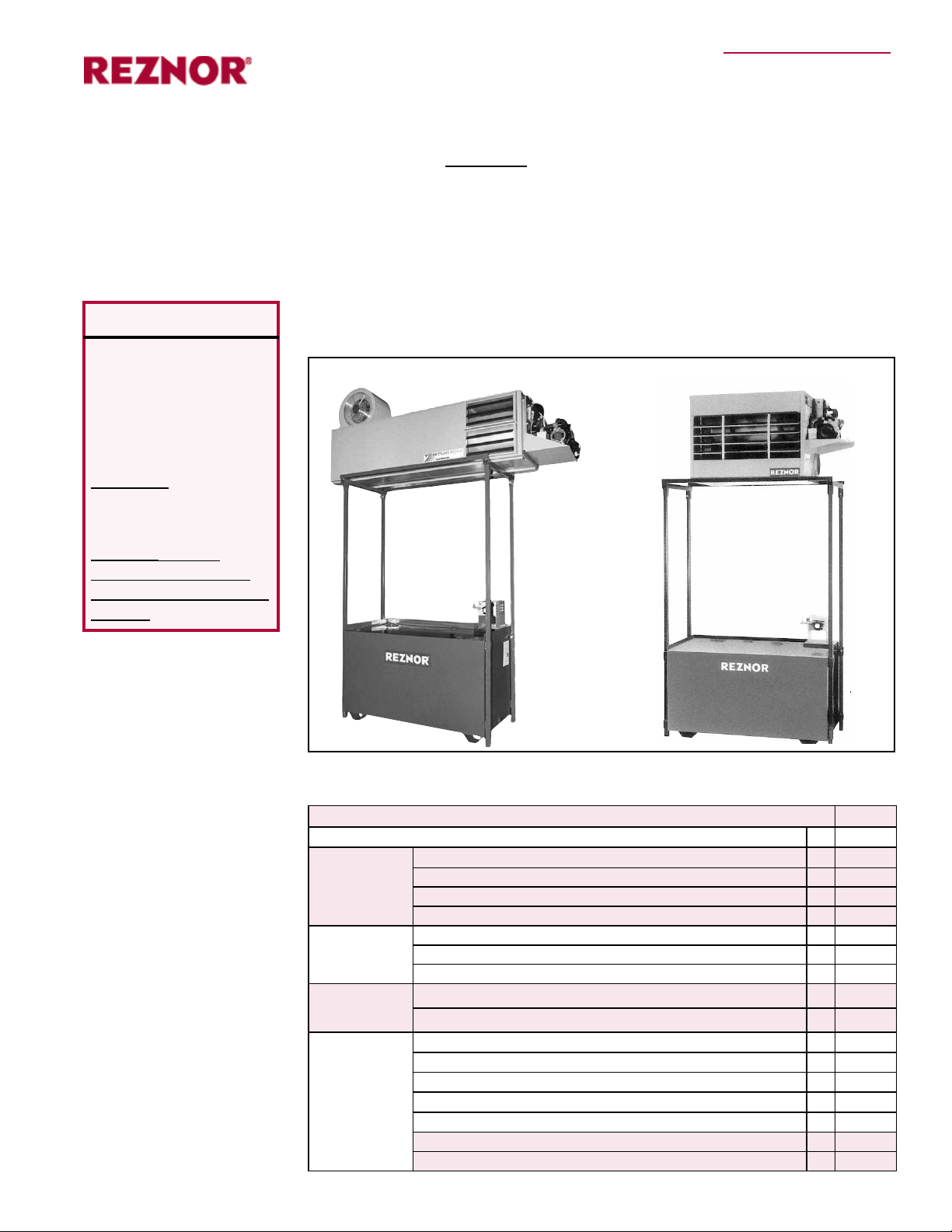
Option ST1 heater stand is designed to be eld-assembled to a Model OT-250
workbench oil tank for the purpose of supporting a Reznor® oil-red unit heater.
Adding the optional stand to the tank creates a unied tank/heater structure. Suspension of the heater is not required when it is installed on the heater stand.
Select a location that will allow for required heater clearances as shown on the
rating plate and in the heater installation manual.
Assembled Tank/Heater Structures using Option ST1
Model
RV225
Model
RA235
Option ST1
Heater Stand
Model OT-250
Workbench
Oil Tank
Components
Before beginning installation, verify components against the list below.
Check for damage. If damage is found, le a claim with the transporting agency.
Option STI Package P/N 202829
Components: Qty P/N
Structural
Parts and
Label for all
installations
Corner
Hardware for
all instalaltions
Setscrew
Hardware for
all installations
Angle Stops
and Hardware
(See
application
listed.)
Corner Post, 1-1/2” square tubing, approximately 8 feet long
Tube Bracket Assembly, 2" square tubing
Warning Label
Front and Rear Support Angle 1-1/2” x 1-1/2” x 64" long
Hex Head Cap Screw, 1/2-13 x 3/4”
Flat Washer, 1/2"
Lock Washer, 1/2"
Hex Head Cap Screw, 1/2-13 x 1-1/2”
Jam Nut, 1/2 -13
Angle Stop, 1-1/2”x1-1/2”x1-1/4" lg w/ 3/8 & 7/32 holes - for OH & RA
Hex Head Cap Screw, 5/16-18 x 3/4” - for OH and RA
Hex Head Nut, 5/16-16 - for OH and RA
Flat Washer, 5/16" - for OH and RA
Lock Washer, 5/16 - for OH and RA
Angle Stop, 1-1/2”x1-1/2”x1-1/4" lg w/ (2) 9/32 holes - for RV
1/4-20 3/4" long F-point Screw - (8) for RV and (4) for RA 150, 250
Form I-OIL-HS, P/N 122407R3, Page 1
4 202826
2 202828
2 121734
2 202827
4 121593
4 121595
4 111306
8 121596
8 45550
4 202825
4 16247
4 1035
4 27761
4 1333
4 202830
8 114687
Page 2
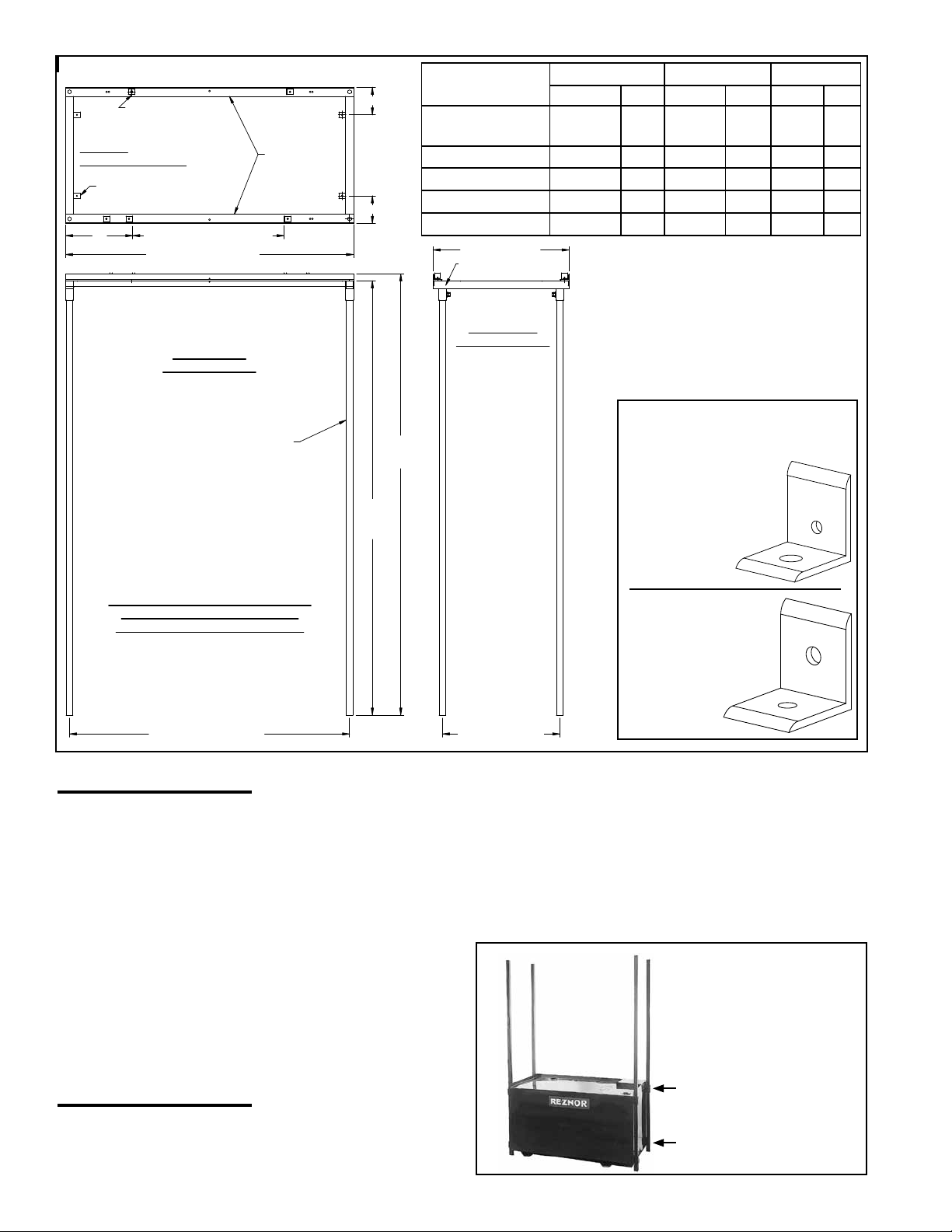
Stand Dimensions
(4) P/N 202825,
Angle Stops (For OH
and RA) - See below.
Top View
of Assembled Stand
(4) P/N 202830, Angle Stops
(For Model RV) - See below,
A
B (Face to Face Angles)
63-1/2” (1613mm)
Front View of
Assembled Stand
(4) P/N 202826
Corner Post
(2) P/N 202827,
Front/Rear
Support Angles
C
C
97-1/4”
(2470mm)
Model/Size
OH 95, 140, 190;
RA 110, 140
RA 235 9-13/16 249 43-3/8 1102
RV 225, 325 -- -- -- -- 6-1/16 154
RA 150 14-7/8 378 33-1/4 845 -- --
RA 250 9-7/8 251 43-1/4 1099 -- --
30” (762mm)
(2) P/N 202828
Tube Bracket Assy
Side View of
Assembled Stand
A B C
inches mm inches mm inches mm
14-13/16 376 33-3/8 848 -- --
Identify Angle Stops to
use by their Hole Sizes
Angle Stop, P/N 202825,
for Models RA and OH
(IMPORTANT: Tank is not shown here,
but stand MUST be installed on a
Model OT-250 Workbench Oil Tank.)
61-3/4” (1568mm)
Instructions
WARNING: Do not
attempt to adapt
this stand to t any
other oil tank; use
only with Reznor
Model OT-250
above ground oil
supply tank. Use
stand only with
®
Reznor
oil-red
unit heater models
and sizes listed on
page 1.
®
95-3/4”
(2432mm)
25-7/8” (657mm)
(1) 3/8 dia hole
(1) 7/32 dia hole
Angle Stop,
P/N 202830,
for Model RV
(2) 9/32 dia holes
1. Model OT-250 Oil Tank – If the tank has not been installed, follow the
handling instructions supplied with the tank. Contact the local re marshal
to assure compliance with local regulations and codes. The oil supply tank
must be installed in accordance with national and local codes.
Proper tank and stand installation is the responsibility of the installer. Select
the tank location with consideration for tank venting requirements, heater
clearances (refer to the heater installation manual), and heater venting. Tank
must be level and stable.
2. Install Heater
Stand Corner
Posts – Slide the
four corner posts
(8-ft lengths of
square tubing) down
Model
OT-250
Oil Tank
Slide the four corner
posts down through
the upper and lower
tank sleeves.
through the upper
and lower sleeves
Upper Tank Sleeve
that are welded to
the ends of the tank.
Lower Tank Sleeve
Form I-OIL-HS, Page 2
Page 3

3. Prepare and Install
Tube Bracket
Assembly
1) Be sure surface is clean
and dry.
2) Position label so that it will
be visible from each side of
the heater stand.
3) Attach labels.
Corner and Angle Stop
Assembly for Models
RA 110, 140, 235 and
Models OH 95, 140, 190
(4) P/N 121593,
1/2-13x3/4” lg
Hex Hd Cap Screw
(4) P/N 111306
1/2 Lockwasher
(4) P/N 121595
1/2 Flat Washer
(2) P/N
121734
Warning
Label
(one on
each side)
IMPORTANT: Position front and rear support
angles with angle positioned UP as shown here.
(4) P/N 16247
5/16-18x3/4” lg
Hex Hd Cap Screw
(4) P/N 1333,
5/16 Lockwasher
(4) P/N 27761,
5/16 Flat Washer
(4) P/N 45550,
1/2-13 Jam Nut
(4) P/N 121596,
1/2-13x1-1/2 lg
Hex Hd Cap Screw
(4) P/N 1035,
5/16-6 Hex Nut
Angle Stop - See
page 2 for selection
and spacing.
(4) P/N 121593,
1/2-13x3/4” lg
Hex Hd Cap Screw
(4) P/N 111306
1/2 Lockwasher
(4) P/N 121595
1/2 Flat Washer
(2) P/N
121734
Warning
Label
(one on
each side)
IMPORTANT: Position front and rear support
angles with angle positioned DOWN as shown
here.
(4) P/N 1333,
5/16 Lockwasher
(4) P/N 45550,
1/2-13 Jam Nut
(4) P/N 1035,
5/16-6 Hex Nut
(4) P/N 121593,
1/2-13x3/4” lg
Hex Hd Cap Screw
(4) P/N 111306
1/2 Lockwasher
(4) P/N 121595
1/2 Flat Washer
(2) P/N
121734
Warning
Label
(one on
each side)
IMPORTANT: Position front and rear support
angles with angle positioned UP as shown
here.
(4) P/N 45550,
1/2-13 Jam Nut
(4) P/N 121596,
1/2-13x1-1/2 lg
Hex Hd Cap Screw
After the Model RV heater is
placed on the stand, use the 3/4”
long F-pointed screws to attach
the angle to the heater bottom.
Attach angle to tube
bracket with a 3/4”
long F-pointed screw.
See page 2 to select
angle and for spacing.
a) Position rails as illustrated,
attaching ends with 3/4” long
screws and washers.
b) At each corner, install the
assembled 1-1/2” cap screw and
jam nut. Follow instructions above.
c) Attach angle stops. See illustration on page 2 for selection and
the table for spacing (A and B).
Corner and Angle Stop
Assembly for Models
RA 150 and 250
Corner and Angle Stop
Assembly for Models
RV 225 and 325
a)
a)
c)
b)
(4) P/N 16247
5/16-18x3/4” lg
Hex Hd Cap Screw
(4) P/N 27761,
5/16 Flat Washer
(4) P/N 121596,
1/2-13x1-1/2 lg
Hex Hd Cap Screw
Angle Stop - See
page 2 for selection
and spacing.
b)
c)
b)
a)
c)
d)
a) Position rails as illustrated,
attaching ends with 3/4” long
screws and washers.
b) At each corner, install the
assembled 1-1/2” cap screw and
jam nut. Follow instructions above.
c) Attach angle stops. See illustration on page 2 for selection and
the table for spacing (A and B).
d) After the heater is centered front
to back on the stand, attach each
angle to the heater side using a
3/4” long F-pointed screw.
a) Position rails as illustrated,
attaching ends with 3/4” long
screws and washers.
b) At each corner, install the
assembled setscrew. Follow
instructions above.
c) Attach angle stops. See illustration on page 2 for selection and
table for spacing (C).
d) After the heater is placed on the
stand, attach each angle to the
heater bottom using a 3/4” long
F-pointed screw.
After a Model RA 150 or 250 heater is
centered front to back on the stand,
use the 3/4” long F-pointed screws to
attach the angles to the heater sides.
d)
the Tube Bracket
Assemblies
Being sure they are in the
correct orientation, attach
a warning label to each
tube bracket assembly.
At the sides of the tank,
connect the posts by sliding a tube bracket down
over the top of each post.
Slide the
tube bracket
assemblies
over the
top of each
corner post.
4. Install Front and
Rear Support Angles,
Corner Setscrews,
and Angle Stops
Select and follow the illustrated instructions for the heater being installed.
Instructions for assembling and installing the eight setscrews used in Steps 4 & 5:
Parts: (8) P/N 121596, 1-1/2” lg cap screws and (8) P/N 45550, jam nuts
Assemble: Thread a nut down the length of each screw.
Install: 1) Thread the assembled screw and nut into the threaded hole.
2) Tighten the screw to 190 in-lbs.
3) Finger tighten the jam nut against the tube or sleeve.
4) Using a wrench, tighten the jam nut 1/8 to 1/4 turn.
Form I-OIL-HS, P/N 122407R3, Page 3
Page 4

At each
Stand
Corner
Post All Models
and Sizes
of Heater
Model OT250
Oil Tank
(4) P/N 121596,
1/2-13x1-1/2” lg
Hex Head Cap Screw
(4) P/N 45550,
1/2-13 Jam Nut
Instructions
(cont’d)
5. Install Setscrews in
Upper Tank Sleeves
Following the instructions
in Step 4, install
the remaining four
assembled setscrews at
the upper tank sleeves.
To stabilize the stand, install
setscrews in upper tank sleeves.
Assembled Setscrew - Install following the
instructions in Step 4, page 3.
Upper Tank Sleeve
Stand Corner Post
6. Assembly of the heater stand is complete. Before setting the heater on the
stand, verify the following:
Are all bolted connections and setscrews tightened sufciently?
Is the tank/stand assembly level and stable?
Will there be adequate clearances to combustibles? (Refer to the heater
rating plate or installation manual.)
Will there be any structural interferences with the heater in place?
7. After the heater is set on the stand and before proceeding with the
installation, attach angle stops to the heater cabinet.
If installing a Model RV, attach the angle stops to the bottom of the heater.
(See the illustration in Step 4, page 3, that appllies to Model RV.)
If installing a Model RA 150 or 250, center the heater front to back on the
stand and attach the angle stops to the sides of the heater. (See the illustration
in Step 4, page 3, that applies to Model RA 150 and 250.)
If installing a Model OH 95, 140, 190 or RA 110, 140, 235, the unit ts between
the rails and does not require that the stops be attached to the heater. However, the screws are included and may be used to attach the angle stops to the
sides of the heater
DANGER: Do not use this heater stand structure to support any weight in addition to
one heater (USE ONLY with one Reznor® Model RA110, RA140, RA150, RA235,
RA250, RV225, RV325, OH95, OH140 or OH190). Maximum weight limit is 500 lbs.
DO NOT use heater stand with models or sizes of heaters not listed.
DANGER: Do not sit on, climb, or hang from any part of the heater stand. Do
not lean a ladder against the heater stand structure or the heater.
Form I-OIL-HS, Page 4
WARNING: For your safety, verify that all applicable procedures in Steps 1-7 have been completed before continuing
with the heater installation.
Used Oil Models RA & RV: www.ReznorHeaters.com; 855-584-3172
No. 2 Oil Model OH: www.RezSpec.com; 800-695-1901
©2014 Reznor, LLC. All rights reserved.
Trademark Note: Reznor
0514 Form I-OIL-HS (Version A.2)
®
is registered in at least the United States.
 Loading...