

Page 1
Form CP-PREEVA-GC (Version A)
Obsoletes Form CP-PREEVA-GC
Gas Conversion Kit Instructions
Applies to: PREEVA
with 1-Stage Gas Control Option AG1 or with 2-Stage
Gas Control Options AG2, AG3, AG15, and AG16
®
Models PDH, SDH, and RDH
General and
Warnings
HAZARD INTENSITY
LEVELS of Warnings
in this Manual
All gas conversion must be done by a qualied service person in compliance with the
National Fuel Gas Code NFPA 54 / ANSI Z223.1 (latest edition), these instructions,
and other applicable codes and requirements.
In Canada, gas conversion shall be carried out in accordance with the requirements of
the Provincial Authorities having jurisdiction and in accordance with the requirements
of the CAN/CSA-B149.1 (latest edition), Natural and Propane Gas Installation Code.
1. DANGER: Failure to comply will result in severe personal injury or death
and/or property damage.
2. WARNING: Failure to comply could result in severe personal injury or
death and/or property damage.
3. CAUTION: Failure to comply could result in minor personal injury and/or
property damage.
WARNING
Improper installation, adjustment, alteration, service,
or maintenance can cause property damage, injury, or
death. Read the installation, operation and maintenance
instructions thoroughly before installing or servicing this
equipment.
FOR YOUR SAFETY
— WHAT TO DO IF YOU SMELL GAS
• Do not try to light any appliance.
• Do not touch any electrical switch; do not use any phone in
your building.
• Leave the building immediately.
• Immediately call your gas supplier from a phone remote
from the building. Follow the gas supplier’s instructions.
• Ifyoucannotreachyourgassupplier,callthere
department.
— Installationandservicemustbeperformedbyaqualied
installer, service agency, or the gas supplier.
Donotstoreorusegasolineorotherammablevaporsandliquidsin
the vicinity of this or any other appliance.
WARNING
The conversion kit is to be selected and installed by a qualied service person
in accordance with these instructions and in compliance with all codes and
requirements of authorities having jurisdiction. Failure to follow instructions
couldresultindeath,seriousinjuryand/orpropertydamage.Thequaliedagency
performing this work assumes responsibility for this conversion.
Form CP-PREEVA-GC, P/N 212063 R7, Page 1
Page 2
General and Warnings (cont’d)
DANGER
The gas burner in this gas-red equipment is designed to provide safe, complete combustion.
However, if the installation does not permit the burner to receive the proper supply of combustion
air, complete combustion may not occur. The result is incomplete combustion which produces
carbon monoxide, a poisonous gas that can cause death.
Safeoperationofindirect-redgasburningequipmentrequiresaproperlyoperatingventsystem
whichvents allueproductstotheoutsideatmosphere. FAILURE TO PROVIDE PROPER VENT-
ING WILL RESULT IN A HEALTH HAZARD WHICH COULD CAUSE SERIOUS PERSONAL INJURY
OR DEATH.
On separated combustion Model SDH heaters, install either the horizontal or vertical combustion
air/vent system illustrated in the heater venting manual, using the concentric adapter supplied.
For all heater installations, always comply with the combustion air requirements in the installation
codes and instructions. Model PDH units installed in a conned space must be supplied with
air for combustion as required by Code and in the heater installation manual. Combustion air at
the burner should be regulated only by manufacturer-provided equipment. NEVER RESTRICT OR
OTHERWISE ALTER THE SUPPLY OF COMBUSTION AIR TO ANY HEATER. MAINTAIN THE VENT
OR VENT/COMBUSTION AIR SYSTEM IN STRUCTURALLY SOUND AND PROPER OPERATING
CONDITION.
Application and Kit
Selection
Gas Conversion
Instructions
The gas conversion kits in these instructions are for Model PDH, Model SDH, and
Model RDH PREEVA® Series packaged heaters equipped with gas control Option AG1,
AG2, AG3, AG15, or AG16. Conversion kits include one or two spring kits for a singlestage valve and one for a two-stage valve. All conversion kits include burner orices
for multiple sizes. See page 7 for conversion kit P/N’s, application, and components.
NOTE: These kits DO NOT APPLY to units with Control Option AG40, AG60, AG61,
AG62, DG1, DG2, DG5, DG6, D12B, D12C, D12F, or D12G). If converting a unit with
any of these control options, contact the factory.
1. Check kit contents for agreement with the parts list and the size of heater being
serviced. (See the parts lists and application for each kit on page 7.)
Conversion of a unit using these kits will not alter the input rate. Refer to the rating
plate on the heater for input rate and other appropriate information.
(NOTE: If adjusted for high altitude operation, input rate will be affected; for high
altitude input ratings and capacities refer to TABLE 3A or 3B, page 8.)
2. Turn off the gas supply at a shutoff valve outside of the heater and turn off
the electrical supply. Open the burner section door.
3. Select and Install the Regulator Spring Kit (valve manufacturer’s conversion
kit)
All conversion kits include one or two regulator spring kits for a single-stage
valve and one for a two-stage valve. Check the package carefully and choose
the regulator spring kit that corresponds with the valve on the heater. NOTE: The
other regulator spring kits will not be used.
Regulator spring kits are not interchangeable. Each spring kit
must be used only in the model and type of valve for which the kit
is designated. Verify compatibility before installing the spring kit.
To install the spring regulator conversion kit, follow the valve manufacturer’s
installation instructions that are included with the spring kit. After a new regulator
spring kit is installed, it is necessary to adjust the spring for the correct manifold
pressure. This adjustment can only be made after the heater is in operation;
instructions are included in Step No. 6.
Form CP-PREEVA-GC, P/N 212063 R7, Page 2
WARNING
Page 3
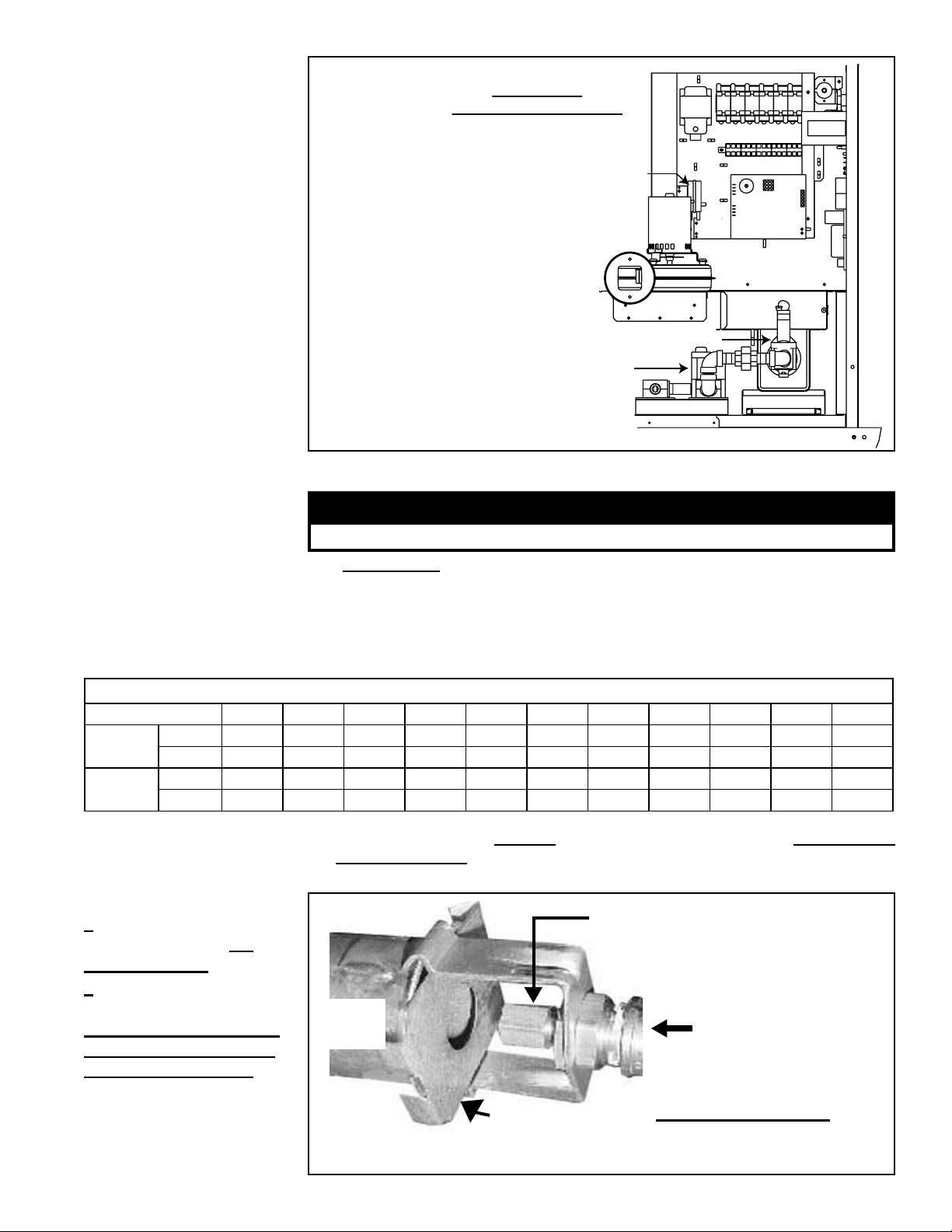
FIGURE 1 - Burner and
Pressure Switch
If installation is above 6000 ft (1830M),
pressure switch may need to
be changed. Follow high altitude
instructions on page 4.
Control Side
Electrical Compartments
Burner with Venturi Tube (See FIGURE 2A)
Gas Valve
Follow manufacturer's
instructions to install
regulator spring kit.
Low Voltage Electrical
Section
(Depending on size,
controls may appear
differently, but conversion
instructions are the
same.)
4.SelectandInstallBurnerOrice
WARNING
TABLE 1 - Burner
OriceP/N’sand
Markings
BurnerOrice-PREEVA® Models PDH, SDH, and RDH
Size 75 100 125 150 175 200 225 250 300 350 400A
Natural
Gas
Propane
P/N 196855 205430 211851 131581 196891 196892 221121 208255 221122 221123 196897
Marking #19 #11 #3 5.9MM E 6.8MM 6.95MM L 8.0MM 8.7MM 9.6MM
P/N 196852 205720 196838 196898 196899 196900 196901 196902 196903 196904 196905
Marking #39 2.9MM #30 9/64" #24 4.1MM 11/64" #14 #8 #3 5.8MM
FIGURE 2A -
1) Location of the
BurnerOriceonall
Models & Sizes
2) Location of the Air
Restrictor Plate on
SIZES 75, 100, 125, 150,
and 175 when installed
for use with Propane
Donotattempttodrillorice.Usefactory-suppliedoriceonly.
4A. Selectorice.
Because each kit is designed to convert more than one size of heater, there are
two or three burner orices per kit. From TABLE 1 below, nd the marking that
appears on the orice for the heater being converted. Select the orice from the
kit that has the marking required for the size of heater. The other orice(s) will
not be used in this conversion.
4B.LocatetheOriceonall Sizes AND the Air Restrictor Plate on Sizes 75, 100,
125, 150, and 175
Refer to FIGURES 2A and 2B.
BurnerOrice(NOTE:Before
installingtheneworice,verify
the marking with the size listed in
TABLE 1, page 3.)
Venturi
Tube
Gas Flow from
Gas Valve
(Tabs are
not bent;
see below.)
Air Restrictor Plate ONLY FOR PROPANE Applies to Sizes 75, 100, 125, 150, and 175
when using propane only.
Form CP-PREEVA-GC, P/N 212063 R7, Page 3
Page 4

Gas Conversion
Instructions
(cont’d)
• Air restrictor plate MUST be added when converting sizes listed to propane. See
FIGURES 2A & 2B and the instructions in Step 4C.
• Air restrictor plate MUST be removed when converting to natural gas. See
FIGURES 2A & 2B and the instructions in Step 4C.
WARNING
Sizes 75, 100, 125, 150, and 175 - Failure to install or remove air restrictor plate according to
directions could cause property damage, personal injury, and/or death.
FIGURE 2B Location of Holding
Tabs on the Air
Restrictor Plate used
on Sizes 75, 100,
125, 150, and 175.
Restrictor plate is
used ONLY when
burning propane on
the sizes listed.
4C. InstallOrice(AllSizes)andInstallorRemoveAirRestrictorPlate(Sizes75,100,125,150,175)
Select and follow instructions in appropriate section in
Step 4C. To install or remove air restrictor plate follow
instructions below.
To install, slide the restrictor in place so that the
45° angle is hooked over the rear of the venturi
tube.
On the front of the venturi tube, bend the two
tabs as shown to hold the restrictor in place.
To remove, carefully unbend tabs.
Natural Gas TO Propane - Applies to Sizes 75, 100, 125, 150, 175
1) Refer to FIGURE 2A and locate the gas orice. Carefully remove the natural gas orice.
2) Install the air restrictor plate. Slide the air restrictor plate over the venturi opening, positioning as illustrated in
FIGURE 2A.
3) Refer to FIGURE 2B. Holding the air restrictor plate in position, use a pair of pliers to bend the tabs to “lock”
the air restrictor plate to the venturi tube. Be sure air restrictor is aligned and secure.
4) Install the propane orice selected for the heater in Step 4A, page 3.
Propane TO Natural Gas - Applies to Sizes 75, 100, 125, 150, 175
1) Refer to FIGURES 1 and 2A and locate the gas orice. Carefully remove the propane gas orice.
2) Refer to FIGURES 2A and 2B and locate the air restrictor plate on the venturi tube. Using a pair of pliers, very
carefully unbend the tabs and remove the air restrictor plate.
3) Install the natural gas orice selected for the heater in Step 4A, page 3.
Natural Gas to Propane OR Propane to Natural - Applies to Sizes 200, 225, 250, 300, 350, 400A
1) Refer to FIGURES 1 and 2A and locate the gas orice. Carefully remove the gas orice.
2) Install the orice selected for the heater in Step 4A, page 3.
Operation Above an
Elevation of 6000 ft
(1830M)
NOTE: If elevation is above 6000 ft (1830M), the unit being converted requires a
high altitude pressure switch. When ordered with Option AB6, AB7, or AB8, the unit is
factory-equipped with a high altitude pressure switch. Verify on the rating plate whether
or not the unit was ordered for above 6000 ft (1830M).
If the unit was not ordered for operation above 6000 ft (1830M) but will be operated
above 6000 ft (1830M) and has a single-stage or two-stage gas control, contact your
distributor to obtain a replacement switch. Follow the instructions below to install the
high altitude pressure switch before starting the heater.
(NOTE: Conversely, if the rating plate does indicate that the unit is equipped for opera-
tion above 6000ft (1830M) and the installation is below that elevation, contact your
distributor to obtain the appropriate pressure switch.)
FIGURE 3 -
Install High
Altitude
Pressure
Switch
required above
6000 ft (1830M)
elevation
Form CP-PREEVA-GC, P/N 212063 R7, Page 4
Pressure
Switch
Instructions for Changing the Pressure Switch
1. In the control compartment, locate the pressure switch.
2. Mark and disconnect the two wires attached to the pressure switch.
3. Disconnect the sensing tube(s) from the pressure switch.
4. Locate the two screws holding the switch mounting bracket.
Remove the screws (save screws) and the pressure switch.
5. Using the same screws, install the correct pressure switch. Attach
the sensing tube(s) and wires.
Page 5

FIGURE 4 - Top View
of Valves identifying
Pressure Taps and
Adjustment Screws
Single-Stage
Valve
(two styles)
5. Turn on the electricity and the gas. Relight, following the instructions on the
heater. Check for gas leaks using a commercial leak detecting uid or a rich soap
and water solution. Leaks are indicated by the presence of bubbles. Check all
connections. If a leak cannot be stopped by tightening, replace the part.
6. Adjust the manifold pressure. Follow these requirements and instructions to
adjust manifold gas pressure.
1) The correct pressure adjustment depends on the area of the country in terms of
elevation. Refer to TABLE 2 and determine the required valve outlet pressure
for the elevation where the heater will be operating. If you don’t know the
elevation, check with your local gas company.
2) Locate the 1/8” output pressure tap on the valve (See FIGURE 4). Turn the
knob or switch on the top of the valve to “OFF”. Connect a manometer to the
1/8” pipe outlet pressure tap in the valve. Use a water column manometer that
is readable to the nearest tenth of an inch.
Adjust Outlet
Pressure
Inlet
Pressure Tap
1/8” Outlet
Pressure Tap
Two-Stage Valve
Adjust High
Fire Outlet
Pressure
Adjust Low
Fire Outlet
Pressure
Adjust Outlet Pressure
Inlet Pressure Tap
TABLE 2 - Valve Outlet
Pressure Settings by
Elevation, Control
Option, and Fuel Type
CAUTION
DO NOT bottom
out the gas
valve regulator
adjusting screw.
This can result
in unregulated
manifold pressure
causing excess
overreandheat
exchanger failure.
Inlet
Pressure
1/8” Outlet
Tap
Pressure Tap
Applies to Model PDH, SDH, and RDH with Gas Controls listed
Altitude
FEET METERS
Manifold Pressure Settings (inches w.c.) by Altitude for Installation in the UNITED STATES
0 - 2000 0 - 610 3.5 10.0 1.8 5.0
2001 - 3000 611 - 915 3.1 8.8 1.6 4.4
3001 - 4000 916 - 1220 3.0 8.5 1.5 4.2
4001- 5000 1221 - 1525 2.8 8.1 1.5 4.1
5001 - 6000 1526 - 1830 2.7 7.7 1.4 3.9
6001 - 7000 1831 - 2135 2.6 7.4 1.3 3.7
7001 - 8000 2136 - 2440 2.5 7.1 1.3 3.5
8001 - 9000 2441 - 2745 2.4 6.7 1.2 3.4
Manifold Pressure Settings (inches w.c.) by Altitude for Installation in CANADA
0 - 2000 0 - 610 3.5 10.0 1.8 5.0
2001 - 4500 611 - 1373 2.8 8.1 1.5 4.1
3) Single-Stage and Two-Stage High Fire - Turn the knob or switch on the top
of the valve to “ON”. Remove the cap from the pressure adjusting screw and
adjust the gas train pressure to the pressure selected from the table. Adjust
pressure by turning the regulator screw IN (clockwise) to increase pressure or
OUT (counterclockwise) to decrease pressure.
Two-Stage Low Fire - Disconnect the wire from the “HI” terminal on the gas
valve and check the low re pressure. Turn the regulator screw to adjust
the low re outlet pressure to the “Low Fire” pressure listed in the table.
Re-connect the wire to the gas valve.
4) Turn up the thermostat. (NOTE: On Model SDH, depress and hold the door
safety switch.) Cycle the burner once or twice to properly seat the adjustment
spring in the valve.
Normal Manifold Pressure (Single-
Stage and Two-Stage High Fire) -
Applies to Options AG1, AG2, AG3,
AG15, AG16
NATURAL PROPANE NATURAL PROPANE
Form CP-PREEVA-GC, P/N 212063 R7, Page 5
2-Stage Low-Fire Manifold
Pressure - Applies to Options
1/8” Outlet
Pressure Tap
AG2, AG3, AG15, AG16
Page 6

Gas Conversion
Instructions (cont’d)
Re-check the pressure. When the outlet pressure is right for the installation,
remove the manometer and replace the cap.
Check for leakage at the pressure tap tting.
5) With the heater operating, determine that the inlet pressure to the heater is
between 5 and 14 inches w.c. for natural gas or between 10 and 14 inches
w.c. for propane. Take this reading as close as possible to the heater. (The gas
valves have an inlet pressure tap; see FIGURE 4.) If the inlet pressure is not
within the specied range, the inlet pressure must be corrected and the manifold (outlet) pressure re-checked.
6) If the gas valve has been adjusted for operation above 2000 ft, nd the High
Altitude Adjustment label in the kit. Using a permanent marker, ll in the appropriate information from TABLE 3, page 8. Select a location for the label on the
outside of the heater so that it will be conspicuous to anyone operating or servicing the unit.
Be sure the surface is clean and dry and adhere the label. (NOTE: At altitudes
from 0-2000 ft (0-610M), this label is not used.)
7. Check for safe and proper operation of the heater by observing operation for at
least one complete cycle. (NOTE: Model SDH, depress and hold the safety door
switch.)
8. Fill in the information required on the gas conversion tape. Select a location near
the rating plate. Be sure the surface is clean and dry and afx the tape to the
heater. Close the door.
De-Coding the
Heater Serial
Number
The identifying model and serial number can be found on the heater rating
plate. When converting fuels, it is necessary that you have the complete heater
model and serial number. See the example below to determine the serial num-
ber valve code. Theratingplateidentiesoriginalequipmentonlysoalso
compare the label on the gas valve with the description listed.
Serial No. Example:
Code for Year and Month the
Heater was Manufactured
Gas Conversion
Kit Application and
Components
BLJ 78 U2 N 99999
Controller
These conversion kits apply only to Model PDH, Model SDH, and Model RDH
with a single-stage gas valve or two-stage control Option AG2, AG3, AG15,
or AG16. Each kit applies only to the sizes listed. All kits include orices and
spring kits that will not be used on all conversions; select parts carefully.
Natural to Propane Kits (Verify kit application.)
Natural TO Propane Conversion Kit, P/N 269846
Applies to: Models PDH, SDH, RDH Sizes 75 and 100
Equipped with one of the following valves:
Serial No. Code Description
Y2 or Z7 VR8205K2957, Single-stage, 1/2”
6E VR8215T1239, Single-stage, 1/2”
Y8 or 4A VR8205N2921, Two-stage, 1/2”
Components:
Qty P/N Description
1 98720
1 260605 Spring Kit #396221 for a VR8215 Single-Stage Valve 6E
1 197207
1 196852 SIZE 75 - Burner Orice, #39
1 205720 SIZE 100 - Burner Orice, 2.9mm
1 202051 Primary Air Restrictor, 1-9/16” (40mm) diameter opening
1 64391 Conversion Tape
1 37752 Propane Gas Disk
1 197062 High Altitude Adjustment Label (use above 2000ft/610M)
Spring Kit #393691 for VR8105, VR8205, VR8305
Single-Stage Valves
Spring Kit #396021 for VR8105, VR8205, VR8305
Two-Stage Valves
Use in
Valve w/
Serial
No. Code
Y2, Z7
Y8, 4A
Ignition
Type of
Valve
Type of Gas
(N = Natural; L = Propane)
Natural TO Propane Conversion Kit, P/N 269847
Applies to: Models PDH, SDH, RDH Sizes 125 and 150
Equipped with one of the following valves:
Serial No. Code Description
Y2 or Z7 VR8205K2957, Single-stage, 1/2”
6E VR8215T1239, Single-stage, 1/2”
Y8 or 4A VR8205N2921, Two-stage, 1/2”
Components:
Qty P/N Description
1 98720
1 260605 Spring Kit #396221 for a VR8215 Single-Stage Valve 6E
1 197207
1 196838 SIZE 125 - Burner Orice, #30
1 196898 SIZE 150 - Burner Orice, 9/64
1 202051 Primary Air Restrictor, 1-9/16” (40mm) diameter opening
1 64391 Conversion Tape
1 37752 Propane Gas Disk
1 197062 High Altitude Adjustment Label (use above 2000ft/610M)
Spring Kit #393691 for VR8105, VR8205, VR8305
Single-Stage Valves
Spring Kit #396021 for VR8105, VR8205, VR8305
Two-Stage Valves
Consecutive
Number
Use in
Valve w/
Serial
No. Code
Y2, Z7
Y8, 4A
Form CP-PREEVA-GC, P/N 212063 R7, Page 6
Page 7

Natural to Propane Kits (cont’d)
(Verify kit application.)
Natural TO Propane Conversion Kit, P/N 269848
Applies to: Models PDH, SDH, RDH Sizes 175, 200, 225
Equipped with one of the following valves:
Serial No. Code Description
Y2 or Z7 VR8205K2957, Single-stage, 1/2”
6E VR8215T1239, Single-stage, 1/2”
Y3 or Z8 VR8305K4241, Single-stage, 3/4”
Y8 or 4A VR8205N2921, Two-stage, 1/2”
Y9 or 5A VR8305N4297, Two-stage, 3/4”
Components:
Qty P/N Description
1 98720
1 260605
1 197207
1 196899 SIZE 175 - Burner Orice, #24
1 196900 SIZE 200 - Burner Orice, 4.1mm
1 196901 SIZE 225 - Burner Orice, 11/64
1 196688
1 64391 Conversion Tape
1 37752 Propane Gas Disk
1 197062
Spring Kit #393691 for VR8105,
VR8205, VR8305 Single-Stage Valves
Spring Kit #396221 for a VR8215
Single-Stage Valve
Spring Kit #396021 for VR8105,
VR8205, VR8305 Two-Stage Valves
Primary Air Restrictor, 1-3/4 (44mm) diameter
opening - Used on Size 175 only
High Altitude Adjustment Label (use above
2000ft/610M)
Use in Valve
w/Serial No.
Code
Y2, Z7, Y3,
Z8
6E
Y8, 4A, Y9,
5A
Propane to Natural Kits
(Verify kit application.)
Propane TO Natural Conversion Kit, P/N 269860
Applies to: Models PDH, SDH, RDH Size 75 and 100
Equipped with one of the following valves:
Serial No. Code Description
Y4 or Z9 VR8205K2965, Single-stage, 1/2”
9E VR8215T5214, Single-stage, 1/2”
Y6 or 2A VR8205N2913, Two-stage, 1/2”
Components:
Qty P/N Description
1 98721
1 261651 Spring Kit #396222 for a VR8215 Single-Stage Valve 9E
1 197208
1 196855 SIZE 75 - Burner Orice, #19
1 205430 SIZE 100 - Burner Orice, # 11
1 64391 Conversion Tape
1 1401 Natural Gas Disk
1 197062 High Altitude Adjustment Label (use above 2000ft/610M)
Spring Kit #394588 for VR8105, VR8205, VR8305
Single-Stage Valves
Spring Kit #396205 for VR8105, VR8205, VR8305
Two-Stage Valves
Propane TO Natural Conversion Kit, P/N 269861
Applies to: Models PDH, SDH, RDH Sizes 125 and 150
Equipped with one of the following valves:
Serial No. Code Description
Y4 or Z9 VR8205K2965, Single-stage, 1/2”
9E VR8215T5214, Single-stage, 1/2”
Y6 or 2A VR8205N2913, Two-stage, 1/2”
Components:
Qty P/N Description
1 98721
1 261651 Spring Kit #396222 for a VR8215 Single-Stage Valve 9E
1 197208
1 211851
1 131581
1 64391
1 1401
1 197062
Spring Kit #394588 for VR8105, VR8205, VR8305
Single-Stage Valves
Spring Kit #396205 for VR8105, VR8205, VR8305
Two-Stage Valves
SIZE 125 - Burner Orice, #3
SIZE 150 - Burner Orice, 5.9mm
Conversion Tape
Natural Gas Disk
High Altitude Adjustment Label (use above 2000ft/610M)
Use in Valve w/
Serial No. Code
Use in Valve w/
Serial No. Code
Natural TO Propane Conversion Kit, P/N 212067
Applies to: Models PDH, SDH, RDH Sizes 250 and 300
Equipped with one of the following valves:
Serial No. Code Description
Y3 or Z8 VR8305K4241, Single-stage, 3/4”
Y9 or 5A VR8305N4297, Two-stage, 3/4”
Components:
Qty P/N Description
1 98720
1 197207
1 196902 SIZE 250 - Burner Orice, #14
1 196903 SIZE 300 - Burner Orice, #8
1 64391 Conversion Tape
1 37752 Propane Gas Disk
1 197062 High Altitude Adjustment Label (use above 2000ft/610M)
Spring Kit #393691 for VR8105, VR8205, VR8305
Single-Stage Valves
Spring Kit #396021 for VR8105, VR8205, VR8305
Two-Stage Valves
Natural TO Propane Conversion Kit, P/N 212068
Applies to: Models PDH, SDH, RDH Sizes 350 and 400A
Equipped with one of the following valves:
Serial No. Code Description
Y3 or Z8 VR8305K4241, Single-stage, 3/4”
Y9 or 5A VR8305N4297, Two-stage, 3/4”
Components:
Qty P/N Description
1 98720
1 197207
1 196904 SIZE 350 - Burner Orice, #3
1 196905 SIZE 400A - Burner Orice, 5.8mm
1 64391 Conversion Tape
1 37752 Propane Gas Disk
1 197062 High Altitude Adjustment Label (use above 2000ft/610M)
Spring Kit #393691 for VR8105, VR8205, VR8305
Single-Stage Valves
Spring Kit #396021 for VR8105, VR8205, VR8305
Two-Stage Valves
Propane TO Natural Conversion Kit, P/N 269862
Applies to: Models PDH, SDH, RDH Sizes 175, 200, 225
Equipped with one of the following valves:
Serial No. Code Description
Y4 or Z9 VR8205K2965, Single-stage, 1/2”
9E VR8215T5214, Single-stage, 1/2”
Y6 or 2A VR8205N2913, Two-stage, 1/2”
Y4, Z9
Y6, 2A
Y5 or 1A VR8305K4241, Single-stage, 3/4”
Y7 or 3A VR8305N4289, Two-stage, 3/4”
Components:
Qty P/N Description
1 98721
1 261651
1 197208
1 196891 SIZE 175 - Burner Orice, E
1 196892 SIZE 200 - Burner Orice, 6.8mm
1 221121 SIZE 225 - Burner Orice, 6.95mm
1 64391 Conversion Tape
1 1401 Natural Gas Disk
1 197062 High Altitude Adjustment Label (use above 2000ft/610M)
Spring Kit #394588 for VR8105,
VR8205, VR8305 Single-Stage Valves
Spring Kit #396222 for a VR8215
Single-Stage Valve
Spring Kit #396205 for VR8105,
VR8205, VR8305 Two-Stage Valves
(Kits for Sizes 250 - 400
Y4, Z9
Y6, 2A
Form CP-PREEVA-GC, P/N 212063 R7, Page 7
Use in Valve w/
Serial No. Code
Y3, Z8
Y9, 5A
Use in Valve w/
Serial No. Code
Y3, Z8
Y9, 5A
Use in Valve w/
Serial No. Code
Y4, Z9, Y5, 1A
9E
Y6, 2A, Y7, 3A
on page 8)
Page 8

Propane to Natural Kits (cont’d) (Verify kit application.)
Propane TO Natural Conversion Kit, P/N 212072
Applies to: Models PDH, SDH, RDH Sizes 250 and 300
Equipped with one of the following valves:
Serial No. Code Description
Y5 or 1A VR8305K4258, Single-stage, 3/4”
Y7 or 3A VR8305N4289, Two-stage, 3/4”
Components:
Qty P/N Description
1 98721
1 197208
Spring Kit #394588 for VR8105, VR8205,
VR8305 Single-Stage Valves
Spring Kit #396205 for VR8105, VR8205,
VR8305 Two-Stage Valves
1 208255 SIZE 250, Burner Orice, L
1 221122 SIZE 300 - Burner Orice, 8.0mm
1 64391 Conversion Tape
1 1401 Natural Gas Disk
1 197062 High Altitude Adjustment Label (use above 2000ft/610M)
High Altitude
Capacity Changes
TABLE 3A - BTUH
Inputs and Capacities
by Altitude in the
UNTIED STATES for
Models PDH, SDH, RDH
2-Stage Minimum
Input NOTE:
“2-Stage Minimum
Input” column” is
70% and applies to
units with 2-stage
control system
Options AG2, AG3,
AG15, and AG16
TABLE 3B - BTUH
Inputs and Capacities
by Altitude in CANADA
for Models PDH, SDH,
RDH
ALTITUDE
Feet Meters Size 75 Size 100 Size 125
0-2000 0-610 75,000 60,750 52,500 100,000 81,000 70,000 125,000 101,250 87,500
2001-3000 611-915 70,500 57,105 49,350 94,000 76,140 65,800 117,500 95,175 82,250
3001-4000 916-1220 69,000 55,890 48,300 92,000 74,520 64,400 115,000 93,150 80,500
4001-5000 1221-1525 67,500 54,675 47,250 90,000 72,900 63,000 112,500 91,125 78,750
5001-6000 1526-1830 66,000 53,460 46,200 88,000 71,280 61,600 110,000 89,100 77,000
6001-7000 1831-2135 64,500 52,245 45,150 86,000 69,660 60,200 107,500 87,075 75,250
7001-8000 2136-2440 63,000 51,030 44,100 84,000 68,040 58,800 105,000 85,050 73,500
8001-9000 2441-2745 61,500 49,815 43,050 82,000 66,420 57,400 102,500 83,025 71,750
Feet Meters Size 150 Size 175 Size 200
0-2000 0-610 150,000 121,500 105,000 175,000 141,750 122,500 200,000 162,000 140,000
2001-3000 611-915 141,000 114,210 98,700 164,500 133,245 115,150 188,000 152,280 131,600
3001-4000 916-1220 138,000 111,780 96,600 161,000 130,410 112,700 184,000 149,040 128,800
4001-5000 1221-1525 135,000 109,350 94,500 157,500 127,575 110,250 180,000 145,800 126,000
5001-6000 1526-1830 132,000 106,920 92,400 154,000 124,740 107,800 176,000 142,560 123,200
6001-7000 1831-2135 129,000 104,490 90,300 150,500 121,905 105,350 172,000 139,320 120,400
7001-8000 2136-2440 126,000 102,060 88,200 147,000 119,070 102,900 168,000 136,080 117,600
8001-9000 2441-2745 123,000 99,630 86,100 143,500 116,235 100,450 164,000 132,840 114,800
Feet Meters Size 225 Size 250 Size 300
0-2000 0-610 225,000 182,250 157,500 250,000 202,500 175,000 300,000 243,000 210,000
2001-3000 611-915 211,500 171,315 148,050 235,000 190,350 164,500 282,000 228,420 197,400
3001-4000 916-1220 207,000 167,670 144,900 230,000 186,300 161,000 276,000 223,560 193,200
4001-5000 1221-1525 202,500 164,025 141,750 225,000 182,250 157,500 270,000 218,700 189,000
5001-6000 1526-1830 198,000 160,380 138,600 220,000 178,200 154,000 264,000 213,840 184,800
6001-7000 1831-2135 193,500 156,735 135,450 215,000 174,150 150,500 258,000 208,980 180,600
7001-8000 2136-2440 189,000 153,090 132,300 210,000 170,100 147,000 252,000 204,120 176,400
8001-9000 2441-2745 184,500 149,445 129,150 205,000 166,050 143,500 246,000 199,260 172,200
Feet Meters Size 350 Size 400A
0-2000 0-610 350,000 283,500 245,000 400,000 324,000 280,000
2001-3000 611-915 329,000 266,490 230,300 376,000 304,560 263,200
3001-4000 916-1220 322,000 260,820 225,400 368,000 298,080 257,600
4001-5000 1221-1525 315,000 255,150 220,500 360,000 291,600 252,000
5001-6000 1526-1830 308,000 249,480 215,600 352,000 285,120 246,400
6001-7000 1831-2135 301,000 243,810 210,700 344,000 278,640 240,800
7001-8000 2136-2440 294,000 238,140 205,800 336,000 272,160 235,200
8001-9000 2441-2745 287,000 232,470 200,900 328,000 265,680 229,600
ALTITUDE
Feet Meters Size 75
0-2000 0-610 75,000 60,750 52,500 100,000 81,000 70,000 125,000 101,250 87,500
2001-4500 611-1373 67,500 54,675 47,250 90,000 72,900 63,000 112,500 91,125 78,750
Feet Meters Size 150 Size 175 Size 200
0-2000 0-610 150,000 121,500 105,000 175,000 141,750 122,500 200,000 162,000 140,000
2001-4500 611-1373 135,000 109,350 94,500 157,500 127,575 110,250 180,000 145,800 126,000
Feet Meters Size 225 Size 250 Size 300
0-2000 0-610 225,000 182,250 157,500 250,000 202,500 175,000 300,000 243,000 210,000
2001-4500 611-1373 202,500 164,025 141,750 225,000 182,250 157,500 270,000 218,700 189,000
Feet Meters Size 350 Size 400A
0-2000 0-610 350,000 283,500 245000 400,000 324,000 280,000
2001-4500 611-1373 315,000 255,150 220500 360,000 291,600 252,000
Use in Valve w/
Serial No. Code
Y5, 1A
Y7, 3A
Normal
Normal
Input
Input
Applies to: Models PDH, SDH, RDH Sizes 350 and 400A
Equipped with one of the following valves:
Serial No. Code Description
Y5 or 1A VR8305K4258, Single-stage, 3/4”
Y7 or 3A VR8305N4289, Two-stage, 3/4”
Components:
Qty P/N Description
1 98721
1 197208
1 221123 SIZE 350 - Burner Orice, 8.7mm
1 196897 SIZE 400A - Burner Orice, 9.6mm
1 64391 Conversion Tape
1 1401 Natural Gas Disk
1 197062 High Altitude Adjustment Label (use above 2000ft/610M)
Thermal
Output
Capacity
Thermal
Output
Capacity
www.RezSpec.com; (800) 695-1901
©2014 Reznor, LLC. All rights reserved.
Trademark Notes: Reznor® and PREEVA® are registered in at least the United States
All other trademarks are the property of their respective owners.
Form CP-PREEVA-GC, P/N 212063 R7, Page 8
0514 (Serial No. Date Code BNE) Form CP-PREEVA-GC (Version A.1)
Propane TO Natural Conversion Kit, P/N 212073
Use in Valve w/
Spring Kit #394588 for VR8105, VR8205,
VR8305 Single-Stage Valves
Spring Kit #396205 for VR8105, VR8205,
VR8305 Two-Stage Valves
2-Stage
Minimum
Input
2-Stage
Minimum
Input
Normal
Normal
Thermal
Input
Input
Output
Capacity
Thermal
Output
Capacity
Size 100 Size 125
2-Stage
Minimum
Input
2-Stage
Minimum
Input
Normal
Input
Normal
Input
Serial No. Code
Y5, 1A
Y7, 3A
Thermal
Output
Capacity
Thermal
Output
Capacity
2-Stage
Minimum
Input
2-Stage
Minimum
Input
 Loading...