

Page 1
NOTE: After installation, keep this
booklet with the makeup air system
installation/operation manual.
OPTIONS AS3, AS4, AS5, AND AS8
EVAPORATIVE COOLING MODULE
INSTALLATION/OPERATION/MAINTENANCE
FORM RZ/NA I-OPT-EC
OBSOLETES FORM 400EC
1. Description/
Application
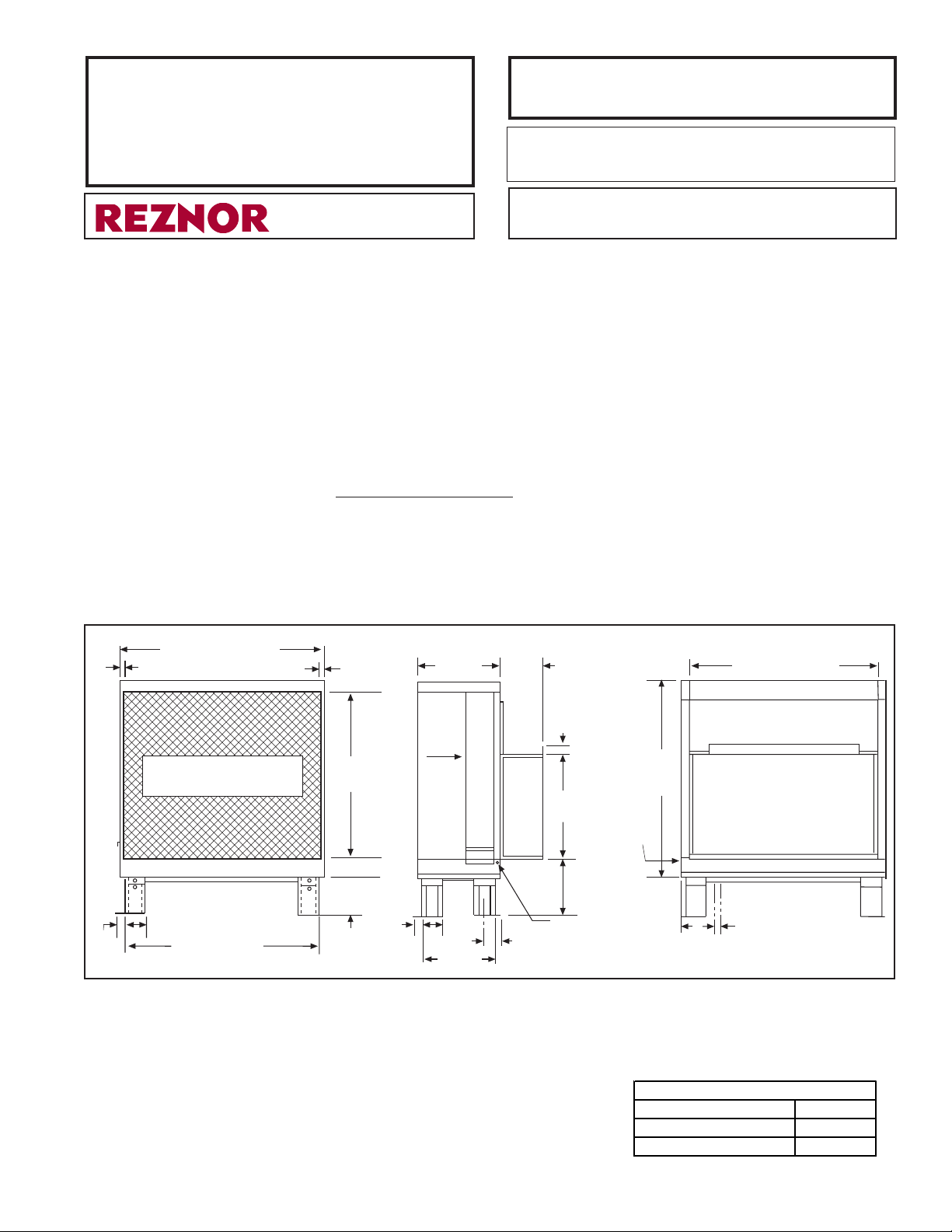
2. Dimensions
58-3/4 (1492mm)
1 (25mm)
1 (25mm)
®
APPLIES TO: Models RGBL,RPBL,SSCBL,PGBL;
Models ADF/ADFH 700/1200; Model RBL
The optional evaporative cooling module for packaged indirect-fired system Model
Series RGBL, RPBL, SSCBL, PGBL, blower cabinet Model RBL, and direct-fired
makeup air Models ADF/ADFH 700/1200 is factory assembled but requires field
installation. Evaporative cooling module Option AS3 includes 6” rigid cellulose
media; Option AS4 includes 12" rigid cellulose media; Option AS5 includes 6"
rigid glass fiber media; and Option AS8 includes 12" rigid glass fiber media. The
base parts for supporting the evaporative cooling module and the transition duct for
connecting it to the unit are shipped with the module for field assembly and installation. If optional moisture elimination pads, a drain and fill kit, and/or a water
hammer arrestor are to be included in the installation, they also require field installation.
Indoor Installation Note: The evaporative cooling module cannot be suspended;
it must be placed on a platform. If the installation is not conducive to providing a
platform for the optional evaporative cooling module to attach directly to the cabinet, install a compatible Reznor ® Model REC evaporative cooling module which
also must be mounted but requires a field-fabricated transition duct and can be
located further away. All evaporative cooling modules require outside air.
24
(610)
12
(305)
54-1/16 (1373)
Opening Size
56-3/4 (1441) x 48 (1219)
Inlet View
2(51)
6 (152)
47-3/4 (1213)
3. Installation
Preparation
Check List:
3 (76)
29-3/4
(756)
Adjustable
21-9/16 (548)
maximum
14-9/16 (370)
minimum
Water Connection
(1/4 tubing)
5-1/32
Drain/Overflow Connection
)
(128
(centerline)
56-5/8
(1438)
Water
Connection
(Control
Side)
Transition Duct Opening
for Reznor Model Series
RGBL, RPBL, SSCBL, and
PGBL; Blower Model RBL;
and Model ADF/ADFH
Sizes 700 and 1200.
Outlet View
9-1/2
(241)
2(51)
Drain/Overflow
Connections
47-3/4
(1213)
5-1/2 (140)
Adjustable Legs
16 (406) maximum
9 (229) minimum
2(51)
AIR
FLOW
Control
Side
View
6 (152)
21-1/2
(546)
Control Pump
Access Panel
o Make certain the installation complies with all local, utility and federal build-
ing and safety codes and regulations.
o Check module for shipping damage. If damage is found, document the damage
with the transporting agency and immediately contact your Reznor Distributor.
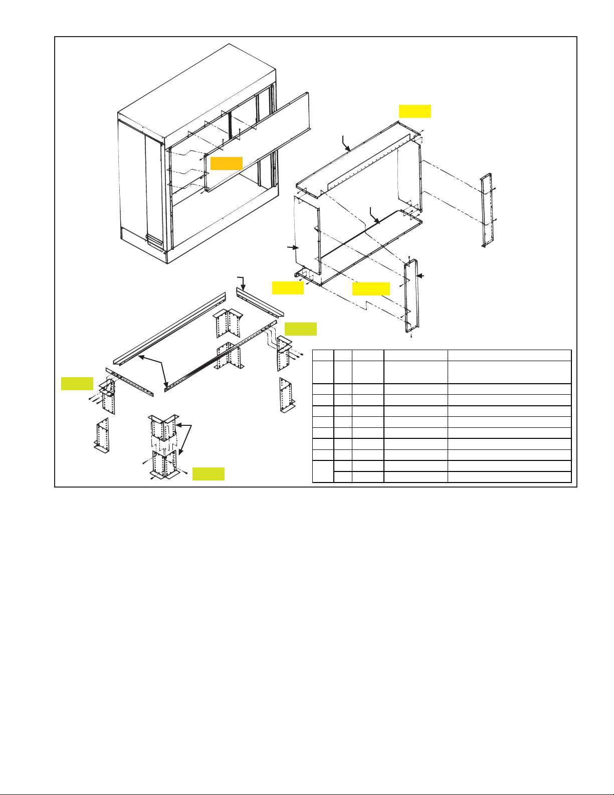
o Check fabricated parts in the duct kit
package against parts list shown in
FIGURE 2, page 3. The package
also includes the hardware listed
here.
Transit ion D uct Hard w are Pack age
#10x1/2” Screws (58) 11813
1/4 - 20 Hex Head Bolts
(10) 16246
1/4 - 20 Nuts (10)16050
Mfg No. 160202, Page 1
Page 2
3. Installation
Preparation
Check List
(cont’d):
In addition, the following parts for making electrical and water connections are
shipped in the bottom pan of the evaporative cooling module.
Qty P/N Descrip ti on
1 105945 1/4" Hose I.D. x 1/2" N.P.T. Bleed Line Fitting (not used
with optional timed metering AquaSaver® system)
2 16835 Bushings, Heyco #SR-7W-2
o If the evaporative cooling module is being installed indoors (Model SSCBL,
PGBL, or ADF/ADFH 700/1200), outside makeup air must be provided.
o If optional shipped-separate equipment will be included (Drain and Fill Kit,
Freeze Protection Kit, Moisture Elimination Pads, and/or Water Hammer
Arrestor), check to be sure that these parts are available for installation.
o Make certain the roof or platform is capable of handling the additional load of
a cooling module with a full reservoir.
Weights of Evaporative Cooling Module - With Wet Media & Full Reservoir
Module with 6" rigid cellulose media (Opt AS3) ............... 379 lbs (172 kg)
Module with 12" rigid cellulose media (Opt AS4) ............ 431 lbs (195 kg)
Module with 6" rigid glass fiber media (Opt AS5) ............. 420 lbs (191 kg)
Module with 12" rigid glass fiber media (Opt AS8) ........... 514 lbs (233 kg)
o Make certain the surface is level and free of debris where cooling module will
be mounted.
o Do not mount directly on soft tar roofs where the legs could sink and tilt the
cooler. Provide a weather-resistant, solid wood or metal base under the cooling
module support base.
o Make certain that there will be adequate clearance between the bottom of the
reservoir and the roof or platform to allow for drain and overflow pipe connections.
4. Base and
Transition
Duct
Installation
Instructions
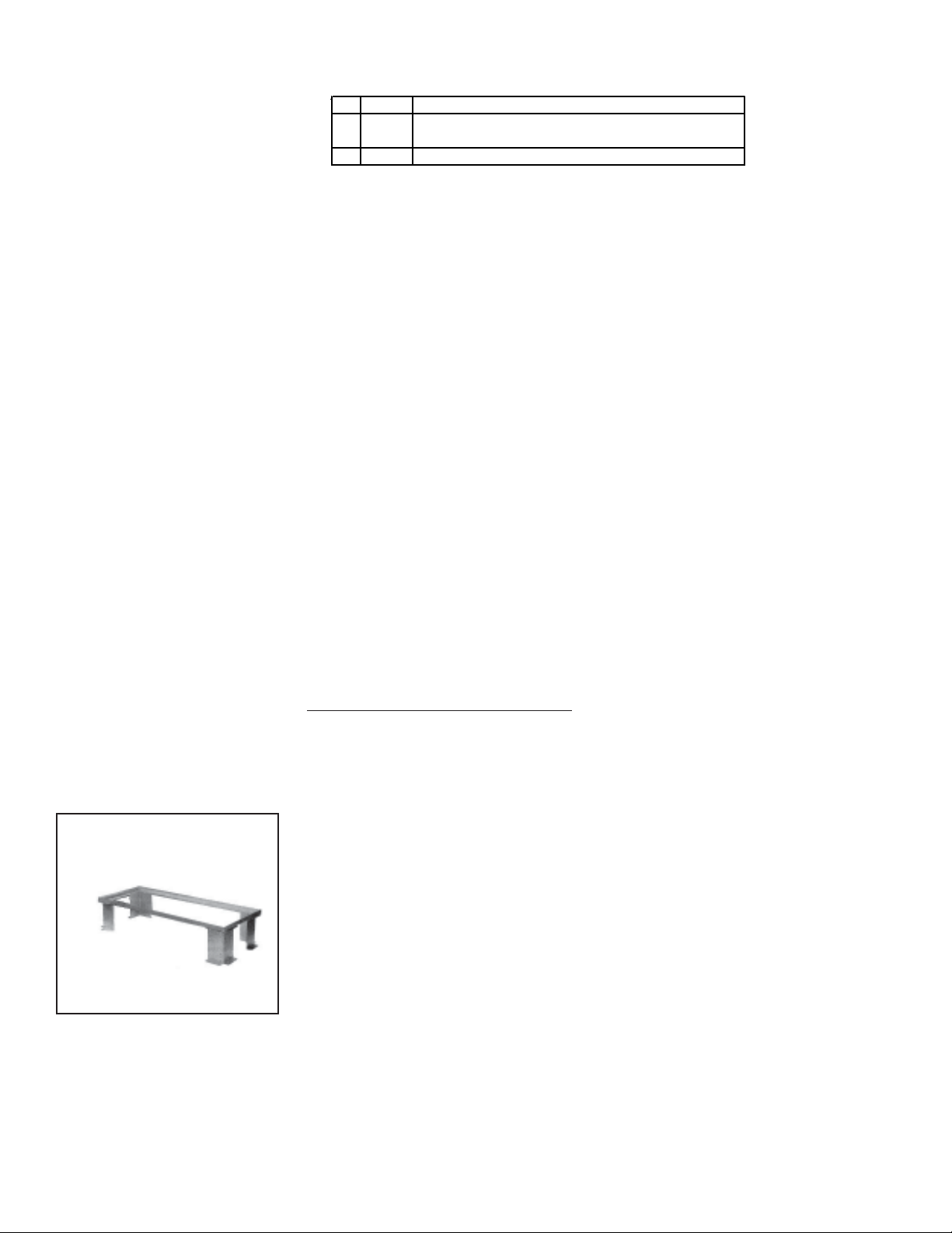
FIGURE 1- Assembled
Base for Evaporative
Cooling Module
Adjustable Leg
Height
16” (406mm) Maximum
9” (229mm) Minimum
Attach the evaporative cooling module after the makeup air unit is in its permanent
location. Do not install the evaporative cooling module and connecting duct while
the blowers are in operation. Steps 2-11 are illustrated on FIGURE 2, page 3.
Steps 12-20 are illustrated in FIGURE 4, page 4.
FOLLOW EACH STEP IN ORDER.
STEP 1:
1) Be sure all preparations have been made. Review Preparation Checklist, pages
1 and 2.
Assembling Base, FIGURE 1 & STEPS 2-5, FIGURE 2:
2) Using four bolts and nuts per leg, fasten the two leg halves (ITEM 4) together.
See FIGURE 2, Step #2. The top flange of the assembled legs should be level
with the bottom of the system cabinet. Adjust legs to proper height and tighten
bolts securely. Assemble all four legs.
3) Approximately two feet (610mm) from the air inlet side of the cabinet, posi-
tion the four assembled legs in a rectangular pattern corresponding to the size
of the cooler. Depending on the type of surface, it may be necessary to set the
legs on a weather-resistant, solid wood or metal base. Check again to be sure
that the top of the legs are level with the bottom of the makeup air system
cabinet.
4) Place rail sides (ITEM 3) on the inside of the top flanges of the leg assemblies.
Using the bolts and nuts provided, bolt the side rail to the top three holes
located on the legs just below the top flange. Repeat on the remaining three
legs. Tighten nuts securely.
5) Place the rail ends (ITEM 2) on the inside of the top flange of the leg assem-
blies. Bolt the end rail to the top three holes located on the legs just below the
top flange. Repeat on the remaining three legs. Tighten nuts securely.
Form I-OPT-EC, Page 2
Page 3
Cooling Module
FIGURE 2 - Parts List and Illustration for
Assembling Base and Transition Duct for
Optional Evaporative Cooling Module
Cooling Module
Base (must
be field
assembled)
Step 4
ITEM 1
ITEM 3 (2)
ITEM 2
(2)
ITEM 4
(4 sets)
Step 2
Step 7
ITEM 7 (2)
ITEM 5
Step 9
Step 5
Step 8
ITEM 6
Transition Duct
(connects cooling
module to makeup
air system)
ITEM 8
ITEM 9 (2)
Step 11
Item Qty P/N Description Where Us ed:
1 Evaporative
1
Cooling Module
2 107235 Support Ends Base Assembly
2
2 107227 Support Sides Base Assembly
3
8 107236 Leg Halves Base Assembly
4
1 107228 Front Top Cover Cooling Module
5
1 107229 Duct Top Transition Duct
6
2 107231 Duct Side Transition Duct
7
1 107230 Duct Bottom Transition Duct
8
2 107233 Duct Extensions “BL” Models 500 and 600
9
2 107234 Duct Extensions “BL” Models 700 and 1050
Used on BL
Sizes 500, 600,
700, & 1050 only.
Not required on
other Models
and Sizes.
Factory-assembled for field
attachment to a makeup air system
Attaching
Cover and
Assembling
Transition
Duct
(FIGURE 2,
STEPS 7-11)
6) Carefully lift the evaporative cooling module (ITEM 1) from both ends and place it on the
completed base assembly. Be certain that the cooling module is level and all base assembly bolts are secure.
7) Attach front top cover (ITEM 5) to cooling module, as shown in STEP #7 using 13 of the
# 10 x 1/2" long sheetmetal screws. There will be three screws per side and seven screws
across the top.
8) Attach transition duct sides (ITEM 7) to duct top (ITEM 6) using eight, #10 x 1/2"
long sheetmetal screws. As shown in STEP #8, there will be four screws per side.
9) Fasten the duct bottom (ITEM 8) to the transition duct sub-assembly begun above
by following STEP #9, using eight of the #10 x 1/2" long sheetmetal screws
provided. Again, there will be four per side.
10)If the packaged heating system is a “BL” 500, 600, 700 or 1050 size, the duct
extensions (ITEM 9) must also be installed on the transition duct. If the packaged
heater is a “BL” 400, 800, or 1200 size, an RBL, or an ADF/ADFH, skip STEP
11 and continue with STEP 12.
11)There are two sizes of the duct extensions. One is used to fit the “BL” 500 or 600
size heaters; one fits the 700 and 1050 size heaters. To fasten the duct extension
(ITEM 9) to the transition duct assembly, use 14 #10 x 1/2" long metal screws as
shown in STEP #11. Five screws will be used on each side of the extension and
one up through the bottom of the extension.
Mfg No. 160202, Page 3
Page 4
Assembling
Transition
Duct (cont’d)
Attaching
Transition
Duct and
Cooling
Module to
System
Cabinet
(FIGURE 4,
STEPS 12-
21):
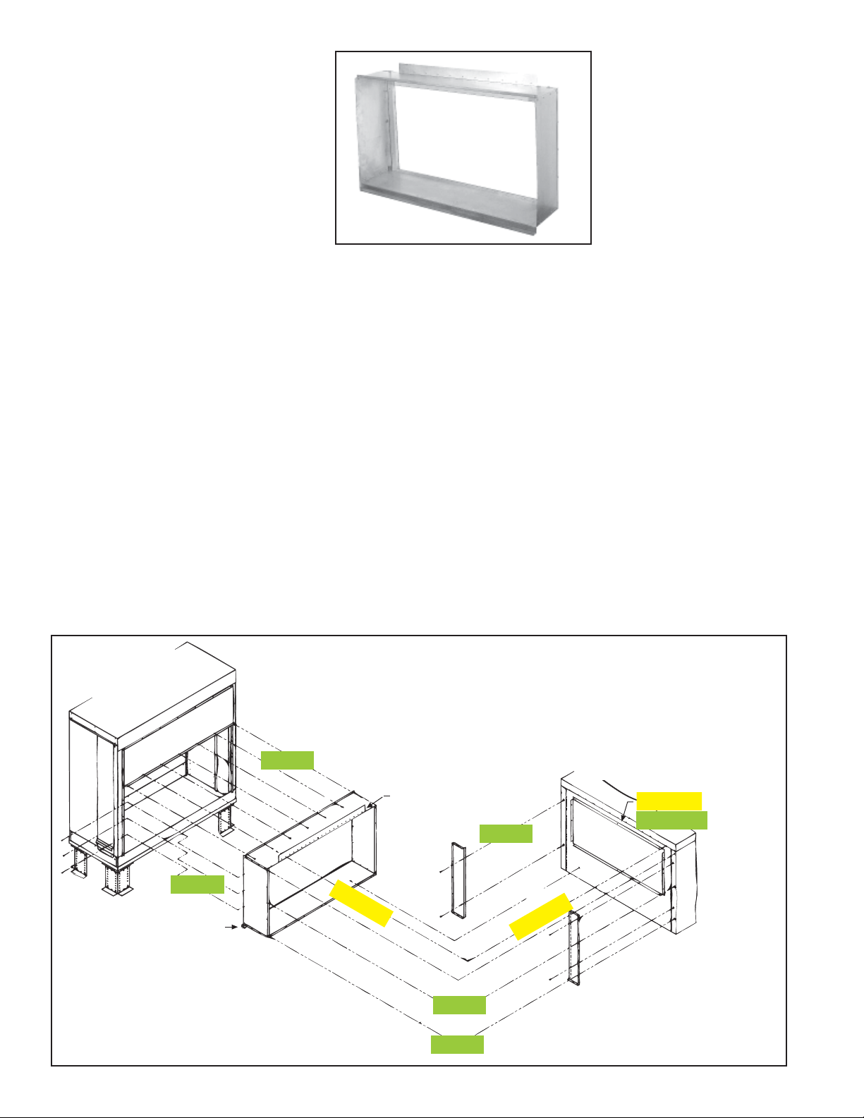
FIGURE 3 Assembled
Transition Duct
12)Following Step #12A, remove the screws from along the top rear lip of the blower
cabinet panel. Slip the transition duct flange underneath the cabinet top edge and
loosely insert two screws through the top edge, through the transition duct flange, and
into the cabinet end panel. Follow STEP #12B.
13)If the transition duct has duct extensions (FIGURE 2, ITEM 9), insert the duct extension
mounting flanges into the slots on the cabinet end panel.
14)With the transition duct attached to the cabinet, carefully tilt the transition duct upward
enough to clear the cooler reservoir pan and slide the evaporative cooling module
underneath the catch pad mounting trough. Squeeze the cooling module and transition
duct assembly into the system cabinet until a tight fit is obtained.
15)Following STEP #15, line up the holes in the cooling module corner leg with the holes in
the transition duct sides. Using five #10 x 1/2" long sheetmetal screws per side, fasten
the transition duct sides to the cooling moduler.
16)Following STEP #16, fasten the transition duct top lip to the front top cover of the
cooling module with seven of the #10 x 1/2" long sheetmetal screws provided.
17)With the cooling module and transition duct properly positioned on the blower cabinet,
tighten the two screws loosely inserted in STEP 12B. Insert and tighten screws in the
remaining holes along top edge of cabinet.
NOTE: When attaching the transition duct to the cabinet (STEP 18 or 19), you may find
it easier with the media pads removed. See FIGURES 5 and 7 and the corresponding
Evaporative
Cooling
Module
Front Top Cover
Catch Pad
Mounting Trough
Step 15
Step 16
FIGURE 4 - Illustration for attaching Transition Duct and
Evaporative Cooling Module to the System Cabinet
(illustration is angled for clarity; actual connections will be
in a straight line)
Makeup Air
Transition
System Cabinet
Duct
Flange (must go under
edge of cabinet top)
Step 12A
& Step 17
Step 19
Step 12B
Step 12B
Duct extensions (if used)
Step 18
are attached to the transition
duct. Duct extension flanges
go into slots on the cabinet.
Step 20
Form I-OPT-EC, Page 4
Page 5
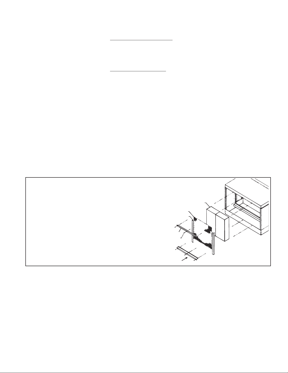
instructions on pages 5 and 6 for removal and replacement of media pads. If
optional moisture elimination pads are being included, media pads will have to
be removed to complete the installation.
18)
If there are no duct extensions on the transition duct, reach inside the cooling
module and fasten the cooler to the back of the cabinet and panel as shown in
STEP #18. There are no holes in the cabinet end panel, so six #10x1/2" long
self-drilling sheetmetal screws must be used. The screws are provided in the
duct kit and are recognizable by their drill bit type cutter and slotted head.
19) If there are duct extensions on the transition duct, reach inside the cooling
module and fasten the duct extensions to the back of the cabinet end panel as
shown in STEP #19. There are no holes in the end panel, so four #10x1/2"
long self-drilling sheetmetal screws must be used. The screws are provided in
the duct kit and are recognizable by their drill bit type cutter and slotted head.
20) Attach bottom of duct assembly, by using seven #10 x 1/2" long self-drilling
screws, to the cabinet end panel as shown in STEP #20.
21) The evaporative cooling module should now be installed. Be certain all
screws are in place. Seal all corners of the transition duct assembly with a
waterproof silicone sealant to prevent moisture from entering the cabinet.
5. Installing Optional Moisture
Elimination
Pads
Option ASA1 moisture elimination pads are shipped separately for field installation. Follow these installation instructions. If this option is not being installed, continue to Paragraph 6.
Media pads must be removed to install the moisture elimination pads (See FIG-
URE 5). FIGURE 6 illustrates installation of the moisture elimination pads.
Remove Media Pads
FIGURE 5 - Removal (and Replacement) of Media Pads
1) Remove the three sheetmetal screws that hold the top
pad retainer.
2) Release the top pad retainer from the cooling module.
3) Remove the three sheetmetal screws that hold the
bottom pad retainer. Release the bottom pad retainer
from the cooling module.
4) Disengage the screen retainers from the sides of the
media.
5) Disengage the inlet screen from the media pads and
remove from the cooling module.
6) Slide all media pads horizontally away from cooling
module until clear of bottom reservoir pan.
Install Moisture
Elimination Pads
(See FIGURE 6,
page 6.)
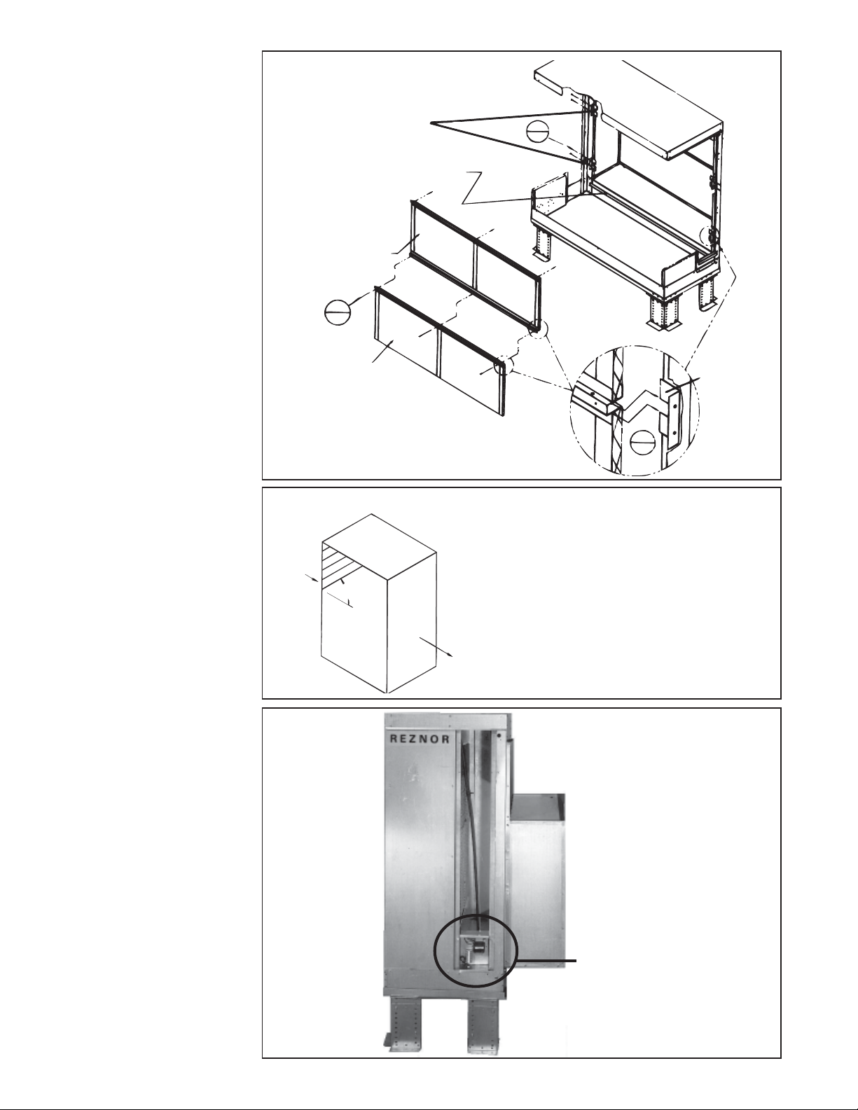
1) Prepare module by attaching two catch pad clamps to one side of the cooler’s
front legs. Screw through the legs into the clamp with four of the #10 x 1/2"
long sheetmetal screws provided.
2) Prepare catch pads by assembling them together. Use three of the #10 x 1/2"
long sheetmetal screws provided.
3) Guide the catch pad assembly through the inlet of the cooling module and
place the bottom of the lower pad into the catch pad mounting trough. The
screen part of the catch pad assembly should always be facing the attached air
mover. Slip the catch pad assembly into the two slots located in the catch pad
clamps installed in Step (1).
4) With the pads in place, complete the assembly by sliding one of the two
remaining clamps over the middle seam where the assembled catch pads meet.
Slip the other clamp over the top catch pad frame and fasten both clamps to
the cooling module leg using sheetmetal screws provided.
Top Pad Retainer
Screen
Screen Retainer
Screw
Bottom Pad
Retainer
Media Pads
Mfg No. 160202, Page 5
Page 6
5. Installing
Optional
Moisture
Elimination
Pads (cont’d)
FIGURE 6 - Installation
of Optional Moisture
Elimination Catch Pads,
Option ASA1
Install clamps on
one side of cooler
Catch Pad Mounting Trough
Catch Pad
Step
2
Step
1
Replace Media
Pads (See FIGURE
5 and FIGURE 7,
page 5.)
Reverse procedure in FIGURE 5 to replace the media.
Media must be installed as
shown in FIGURE 7.
6. Re-Position
Pump/
Junction Box
Assembly
To avoid shipping damage, the
pump/junction box assembly is
attached to the top of the side
panel for shipment. Support the
pump and remove the four
screws that hold the assembly
in position. Re-position the as-
sembly as shown in FIGURE
8 and attach using the same
screws.
Catch Pad
Step
3
FIGURE 7 - Airflow Direction through the Media Pads
IMPORTANT: Cooling media is made
Outside
Airflow
45°
up of two different sheets of cooling
material. Each has its own unique
angle. When replacing the cooing
media, BE CERTAIN the 45° angle
slopes downward toward the incoming
outside air. If the media is not installed
Airflow
to Space
properly , water blo woff from the
media pads will occur.
FIGURE 8 Re-position
pump/
junction box
For shipping, pump/
junction box is
attached at the top.
assembly.
Remove pump/
junction box from shipping
position (above) and re-attach
in “working” position
(illustrated).
Catch Pad
Clamp
Form I-OPT-EC, Page 6
Page 7
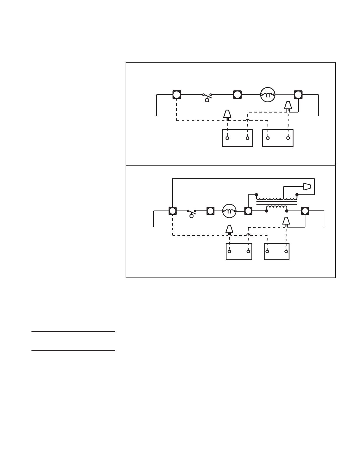
7. Electrical
Connections
Line voltage wiring must be field installed between the blower junction box and the
evaporative cooling module junction box. The tubing-encased wires are factoryconnected in the cooling module junction box.
NOTE: Models ADF/ADFH have only 115V optional evaporative cooling module
pumps. A transformer is included on the unit.
FIGURE 9A - Diagram of
Evaporative Cooling
Module Factory-Installed
Wiring -- “BL” Models
with 115/230/1/60 or 230/
460/575/3/60 (Heater
Options AK3, 6, 7 or 8) and
Models ADF/ADFH 700/
1200 (see Note above)
FIGURE 9B - Diagram of
Evaporative Cooling
Module Factory-Installed
Wiring -- Systems with 208/
1-3/60 (Heater Option AK2
or AK5)
EVAPORATIVE COOLING MODULE
BK
W
V
COOLING CIRCUIT
115-230/1/60
111145 REV #4
EVAPORATIVE COOLING MODULE
Y
SWITCH
BK
W
V
FLOAT
SWITCH
PUMP MOTOR
W BK
H
LINE VOLT
PUMP MOTOR
W BK
H
N.O. TWO WAY
DRAIN VALVE FILL VALVE
BUCK-BOOST
40 VA. TRANSFORMER
BK
230 VOLTFLOAT
BK
I
OPTIONALOPTIONAL
THREE WAY
BL BR
BK
Y
J
Y
R
Y
Y
J
Y
Instructions for
“Internal FieldRequired Wiring
From Cooling Module
to System Cabinet
WARNING: Disconnect
power to the unit.
208/1/60
COOLING CIRCUIT
OPTIONALOPTIONAL
THREE WAY
111452 REV #4
N.O. TWO WAY
DRAIN VALVE FILL VALVE
NOTE: The two snap strain relief bushings are shipped in the bottom pan of the
cooling module.
1. Remove the compartment door panels and electrical compartment cover.
Remove the service panel in line with the hole in the cooling module.
2. Drill a 7/8" hole in the cabinet end panel in line with the hole in the cooling
module junction box.
3. Pull the tubing-encased wires through the hole in the blower cabinet. Place the
strain relief bushings around the tubing and insert the bushing into the hole
(Bushing must be used to prevent water from leaking into the cabinet). Route
the wires across the cabinet bottom. If there are any filters, run the wires
through the slot in the bottom filter rack. If there are inlet dampers, be careful
that the wires do not interfere with the damper controls. Run the wires up to
the electrical compartment, remove a plug from one of the bottom entrance
hole, and push the tubing-encased wires into the electrical compartment. Place
the other strain relief bushing around the tubing and insert the bushing into the
hole in the electrical compartment.
4. Follow the wiring diagram included with the heater to properly connect the
wires to the terminal blocks. If there is excess tubing and/or wiring, trim
before making connections.
5. Before unit is operated, replace all door panels and fasten all latches.
Mfg No. 160202, Page 7
Page 8
Evaporative
Cooling
Module
Float valve inlet water connection
(1/4 compression) or inlet water
connection to solenoid valve
for metering system (1/2 male fitting)
Overflow fitting -
3/4 garden hose
thread tapped with
1/2 female NPT
Drain fitting - 3/4
garden hose thread
tapped with
1/2 female NPT
2-way solenoid valve
(normally open)
3-way
solenoid
valve
To drain
Pressure regulator
(10 psi max)
Service valve
Roof
= Field-installed water piping
A (N.O.)
B (N.C.)
Water
inlet
= Field supplied
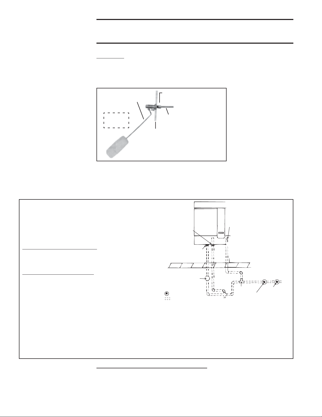
8. Water
Connections
FIGURE 10 - Connect
Fresh Water Supply to
Inlet of Float Valve
WARNINGS: Water reservoir (outdoor systems) must be drained
and pump motor turned off when outside temperature falls below
32°F. Pump must never be operated without water in the reservoir.
Supply and Drain Water Connections
Float Valve (FIGURE 10) - In a module with pump and float controls, a float valve
maintains the appropriate water level in the reservoir.
Use a field-supplied 1/4" diameter tubing with a compression nut and tubing ferrule to
connect the fresh water supply to the inlet of the float valve. Place nut and ferrule over
tubing and insert tubing into the float valve stem. Tighten nut securely.
Compression Nut and
Float Valve Rod
Tubing Ferrule
FIGURE 11 - Water
Connections including
Optional Drain and Fill
Kit
Instructions for Installing Optional Fill & Drain Kit
NOTE: Follow instructions included in the valve packages for attaching valves to the water line only. The remainder of the installation instructions with the valves do
not apply to this type of application.
W ater Line Connections (See illustration.):
Supply (3-Way Valve) Connections - Connect the water
supply line to "B" (normally closed). Connect the water drain
line to "A" (normally open). Connect the middle outlet to
supply the water to the cooling module reservoir.
Drain (2-Way Valve) Connections - Connect the drain pipe
from the reservoir to "A". Connect the outlet side to "B" and
connect into drain lines from the cooling reservoir and the
supply valve.
Electrical Connections (requires black and white 14-gauge
wire) - Refer to Wiring Diagram provided with the furnace:
WARNING: Risk of electrical shock. Disconnect the power.
1. Refer to the wiring diagram for terminal connections.
(NOTE: If kit is not ordered with the system, connections
will not be shown on the diagram. Terminal connections
are specific to each system. Contact the factory for
terminal connections. Be prepared to provide all model
information. )
Form I-OPT-EC, Page 8
An optional automatic fill and drain kit will automatically release supply water to the
cooling module when a call for cooling is made and will drain all water from the
reservoir when the cooling switch is deactivated or a cooling thermostat is satisfied. If
installing an optional fill and drain kit, see FIGURE 11 and follow the instructions that
apply. Consult the wiring diagram for electrical connections.
AquaSaver Timed Metering Control System - If the cooling module is equipped
with a timed metering system, connect a 1/2" water line to the fitting on the side of the
cooling module.
Due to various water pressures and installation conditions, the water supply line may
bang abruptly when the solenoid valve in the AquaSaver system closes. This banging
Inside
Cabinet
Use 1/4” tubing for
fresh water supply.
Simulates
Side
Panel
2. Run field-supplied black wire from the electrical
compartment (terminal on the wiring diagram) of the
evaporative cooling module and connect to the black
wire on both the 3-way and the 2-way valve.
3. Run field-supplied white wire from the electrical
compartment (terminal on the wiring diagram) of the
evaporative cooling module and connect to the white
wire on both the 3-way and the 2-way valve.
Page 9
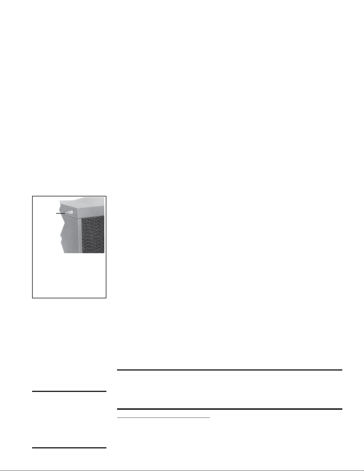
can be minimized by installing a water hammer arrestor in the supply line. If installing
an optional water hammer arrestor, select an indoor (above 32°F) location, either horizontal or vertical, in line with and as close to the solenoid valve as possible. Follow the
manufacturer's instructions to install and maintain the water hammer arrestor.
A freeze protection kit is available for a module with a timed control system. It includes
a two-way valve and is shipped separately for field installation.
All Cooling Modules - A manual water shutoff should be installed upstream of the
inlet, at a convenient non-freezing location, to allow the water supply to be turned on
and off. If necessary, install a bleed line between the manual valve and the cooling
module inlet to allow drainage of the line between the shutoff valve and the cooling
module.
All cooling modules are equipped with an overflow and drain fitting. The fittings are in
the cabinet bottom and come complete with a locknut and a sealing gasket. Check these
fittings for tightness before installing the overflow and drain piping. The drain and
overflow fitting will accommodate a 3/4" garden hose thread and is tapped with a 1/2"
female pipe thread for iron pipe.
FIGURE 12 - Air Inlet
Side of Evaporative
Cooling Module
Showing Bleed Line
Fitting
Bleed
Line
Fitting
Install bleed line
fitting (shipped in the
bottom pan of the
evaporative cooling
module).
Bleed Line Connection (module equipped with pump and float controls only; does not
apply to module with AquaSaver
nylon bleed line fitting (shipped in evaporative cooler bottom pan), thread the fitting
into the female adapter on the distribution pipe. The hose barb will protrude from the
side of the cabinet (See FIGURE 12). Attach a 1/4" I.D. hose to the barb and run to the
nearest drain.
Discharging a quantity of water by “bleed off” will limit the concentration of undesirable minerals in the water being circulated through the cooling module. Minerals buildup
because evaporation only releases “pure water vapor” causing the concentration of contaminants in the water to increase as the evaporation process continues to occur. The
minerals accumulate on the media, in the water lines, on the pump, and in the reservoir.
Adequate bleed off is important to maintaining an efficiently operating evaporative cooling system.
Filling and Adjusting the W ater Level in the Reserv oir (module equipped with pump
and float controls only; does not apply to module with AquaSaver
trols) – Turn on the water supply. Check for a good flow. When the float valve (FIG-
URE 10) shuts off the water supply, measure the water depth. The depth of the water
should be approximately 3". It may be necessary to adjust the float valve to obtain the
proper water level or to free the float valve from obstructions. To adjust the float valve,
carefully bend the float valve rod upward to raise the water level or downward the
decrease the water level.
While the reservoir is full, check for any water leaks. The reservoir was tested, but if
any small leaks are present, drain the reservoir and apply a waterproof silicone sealer
around corners and welds.
timed controls) – Using the 1/4" I.D. x 1/2" N.P.T.
timed metering con-
9. Adjust
Water Flow
Over Pads
WARNING: Adjust
ball valve only when
power is disconnected
from the unit. Failure
to do so can cause
electrical shock, per-
sonal injury, or death.
Proper water flow over the evaporative cooling media is critical to extend the life and
maintain the efficiency of the pads.
CAUTION: Do not flood the media pads with extr eme quantities of water for long periods
as this will cause premature breakdo wn of the media. An even flow fr om top to bottom of
the media with the least amount of water is all that is required to assure maximum
efficiency and media life span. More water does not provide more evaporation or more
cooling.
Float and Pump Control System - Using the ball valve (FIGURE 13, page 10), lo-
cated in the middle of the length of hose running from the pump to the sprinkler pipe
inlet, adjust the valve handle to allow the flow to completely dampen the media pads
from top to bottom.
Mfg No. 160202, Page 9
Page 10
9. Adjust
Water Flow
Over Pads
(cont’d)
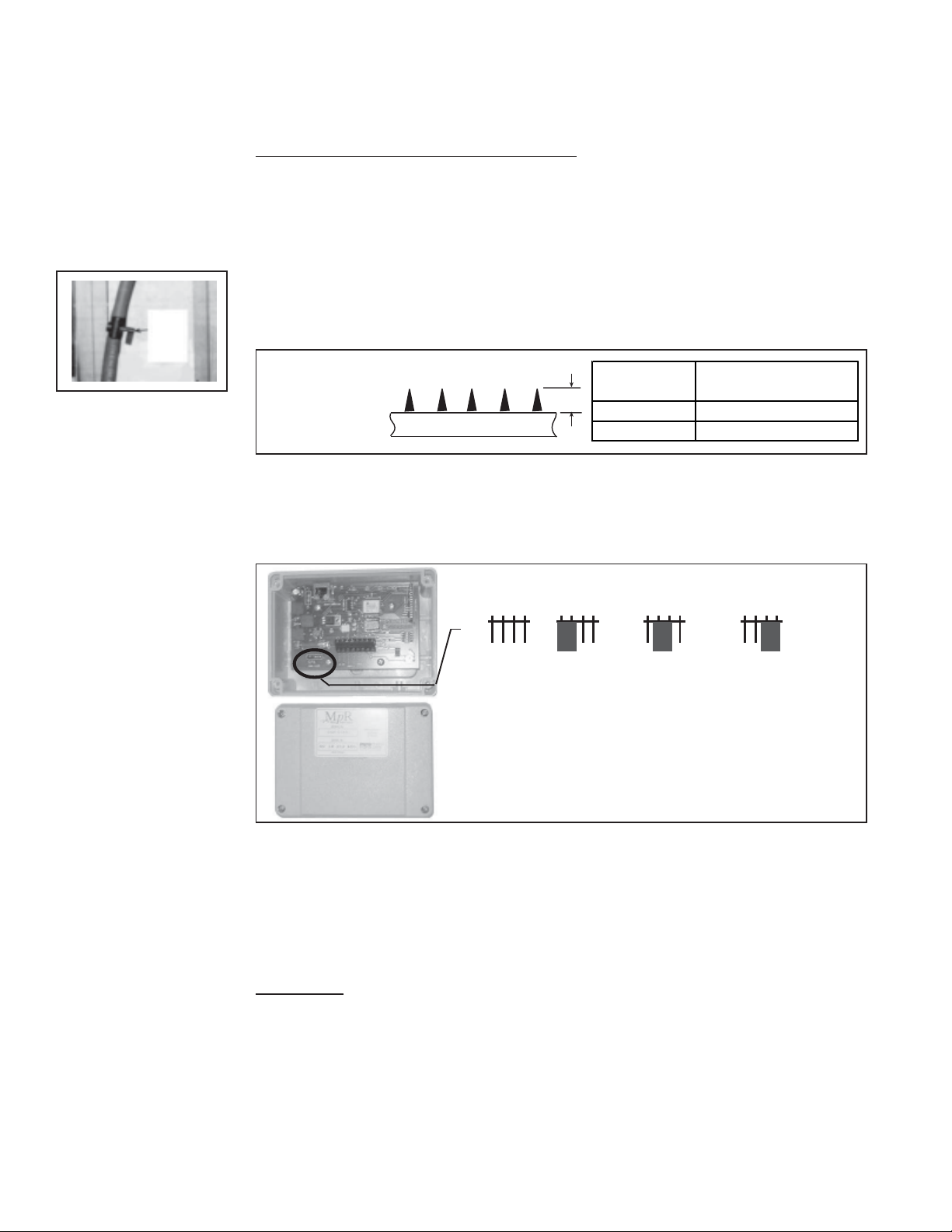
FIGURE 13 - Disconnect the power and
adjust the water flow
with the ball valve.
Ball
V alve
Operate the unit watching the water flow. After 15 minutes with the blower in operation,
the water should have completely dampened the pads but should not be flowing off the
entering side of the media. If water is flowing off the entering side of the media, turn the
system off, disconnect the power, and reduce the entering water flow.
AquaSaver Timed Metering Control System - NOTE: Water flow and pad wetting time
should be adjusted at maximum airflow and wet bulb depression to assure complete wetting of the media at the extreme operating conditions.
In addition to adjusting water flow, the timing of the water on/off cycle can be adjusted.
Adjustments are correct when l) the water rises from the holes in the sprinkler pipe (See
FIGURE 14) consistently along the entire pipe length, 2) the media pads wet evenly after
a few "ON" cycles (no dry spots or dry streaks), and 3) a slight amount of excess water
collects at the drain at the completion of the "ON" cycle.
1) AquaSaver Water Flow Adjustment - Using the ball valve illustrated in FIGURE
13, adjust the water flow depending on the pad height. See FIGURE 14.
FIGURE 14 Adjust W ater
Flow with the
Ball Valve in
Sprinkler Pipe
FIGURE 13.
2) AquaSaver Timer Adjustment - At any given temperature, the media pads should
completely wet from top to bottom during the ON cycle. The microprocessor has three
preset timing settings based on media size. The appropriate setting is selected by
changing the position of the suitcase jumper at J2 on the microprocessor. Remove the
cover and check the setting (See FIGURE 15).
Pad Height
A
24" (610mm) 1/8" to 1/2" (3 to 13mm)
48" (1219mm) 1/4" to 1/2" (6 to 13mm)
= Water rise from PVC
A
Sprink ler Pipe
FIGURE 15 AquaSaver
Microprocessor
Control in the
Junction Box
1 2 3 4 1 2 3 4 1 2 3 4 1 2 3 4
S
J2
12-36
(305-914mm)
Media
Height
NOTE: Prior to 2003 the AquaSaver timed cycle was con-
trolled by a mechanical timer. Turn the adjustment screw
clockwise to increase the ON time or counterclockwise to
decrease the ON time. One complete turn will adjust the
cycle by 12 to 14 seconds.
If the jumper is at the appropriate location for the media, replace the cover. If the jumper
needs to be moved, move it to the appropriate setting. The setting will go into effect when
the power is restored.
Check the "ON" timing; the media pads should be wet from top to bottom during the ON
cycle.
If the preset timing is not suitable for the application, follow the instructions supplied
with the microprocessor to change the calibration of the "On" and/or "Off" cycle.
All Modules - Check the reservoir for any water leaks. The reservoir was water tested, but
if any small leaks are present, drain the reservoir and apply a waterproof silicone sealer
around corners and welds.
M
37-48
(940-1219mm)
Media
Height
L
49-72
(1245-1829mm)
Media
Height
Maintenance
10. Media
Form I-OPT-EC, Page 10
Media - Over time, excessive amounts of mineral deposits will begin to build up on the
media. Annually, scale and dirt should be washed off the entering surface of the media.
Remove the pad retainers and screen. Clean the media using a garden hose, mild soap, and
a soft bristled brush. When the media becomes too clogged with mineral deposits and dirt
that it cannot be cleaned, the pads should be replaced. The average pad life is approximately three cooling seasons.
Page 11
WARNING:
Disconnect all
power to the unit
before doing any
maintenance.
Failure to do so
may cause
electrical shock,
personal injury or
death.
Instructions
for Replacing
Evaporative
Cooling Media
Pads
(FIGURE 16)
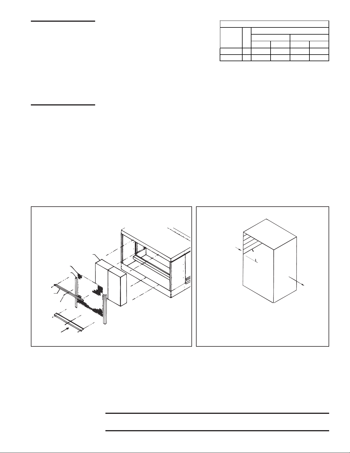
Select the correct replacement part numbers
and order replacement media pads through
your Reznor Distributor. Follow the instructions below and remove and replace pads as
shown in FIGURES 16 and 17.
1. Remove the three sheetmetal screws that hold the top pad retainer in place. Release
the top pad retainer from the cooling module.
2. Remove the three sheetmetal screws that hold the bottom pad retainer in place.
Release the bottom pad retainer from the cooling module.
3. Disengage the screen retainers from the sides of the media.
4. Disengage the inlet screen from the media pads and remove from the cooling module.
5. Slide all media pads horizontally away from the cooling module until clear of bottom
reservoir pan. Dispose of media properly.
6. Slide new media pads over both support rails until back stop is encountered. Media
MUST be placed with airflow as shown in FIGURE 17.
7. Center screen on the incoming air side of the media.
8. Re-position the two side screen retainers by fitting them between the side of the
media pad and the side of the cooling module. The retainers should fit snugly, pinching the screen against the media pads.
9. Position the bottom pad retainer between the pad and the reservoir pan. Fasten with
the three sheetmetal screws removed in Step 2.
10. Position the top pad retainer between the pad and the top of the cooling module.
Fasten with the three sheetmetal screws removed in Step 1.
Evap orative Coo ling M odu le Media Pads
Media
Pad
Sizes 6” 12” 6” 12”
48x12 4 107190 107194 107199 107201
48x8-5/8 1 107191 107195 107200 107202
Qty
Rep lacemen t Part N o.
Cellulose Glass Fiber
FIGURE 16 - Removal and Replacement of
Evaporative Cooling Media
Media Pads
Screen
Screen Retainer
Top Pad
Retainer
Screw
Bottom Pad
Retainer
11. Water
Lines
12. Water
Pump
W ater Feed Line and PVC Distribution Piping – Annually, the water supply line and the
PVC water distribution pipe should be flushed of debris and contaminants. Remove the
media pads following the instructions above. Remove the water feed line from the downstream side of the ball valve and unscrew the water bleed line barbed hose fitting. Force a
fresh water supply up through the water inlet hose and thoroughly flush the distribution
pipe.
Water Pump and Inlet Basket Screen – Annually, the pump and inlet basket should be
removed, disassembled and cleaned.
WARNING: Do not expose pump motor or any part of the electrical
box to water. Evaporative cooling pump is NOT submersible.
FIGURE 17 - Airflow Direction through
Media Pad
Outside
Airflow
45°
Airflow
to Space
IMPORTANT: Cooling media is made up of two differ-
ent sheets of cooling material. Each has its own unique
angle. When replacing the cooling media, BE CERTAIN
the 45° angle slopes downward toward the incoming outside air. If the media is not installed properly, water
blowoff from the media pads will occur.
Mfg No. 160202, Page 11
Page 12
Maintenance
(cont’d)
12. Water
Pump
(cont’d)
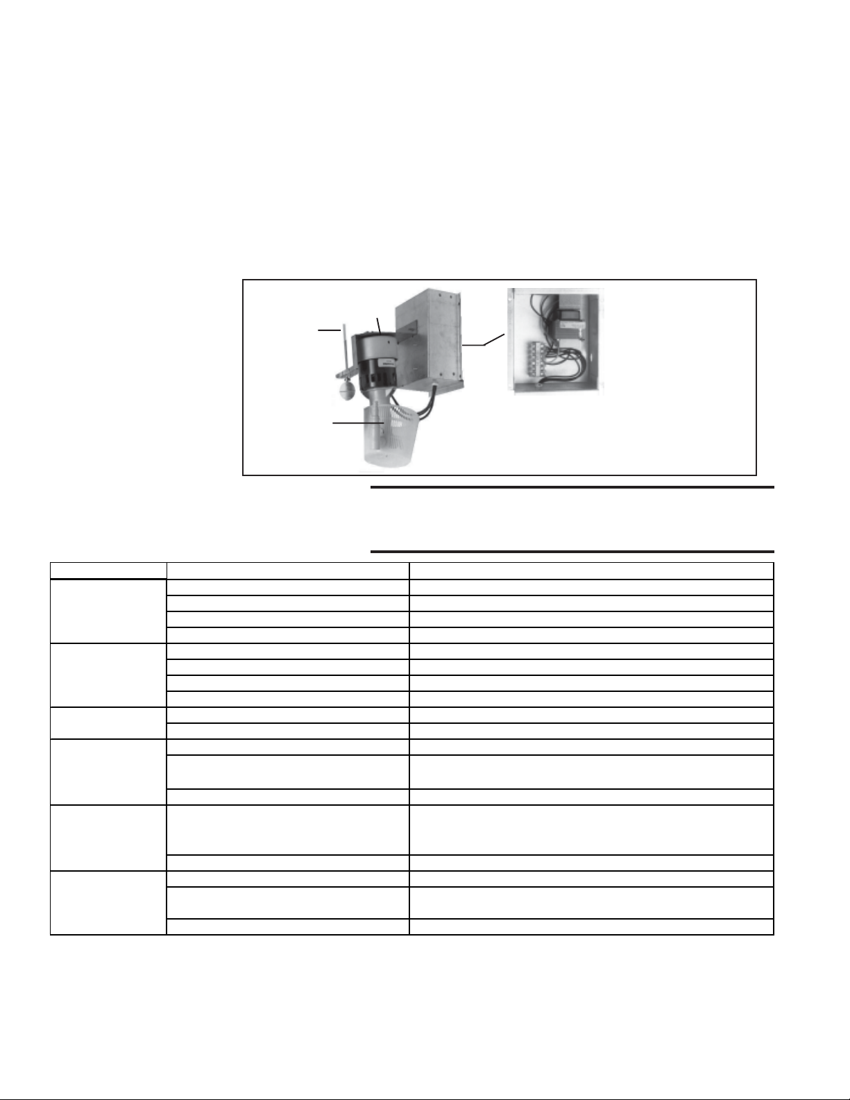
FIGURE 18 Remove Junction
Box, Pump and
Float Switch as an
Assembly
1. Disconnect the power supply to the unit.
2. Remove the junction box door and disconnect the two power supply wires from the
terminal block inside the junction box.
3. Disconnect the water feed line hose from the upstream side of the ball valve.
4. Unscrew the four sheetmetal screws holding the junction box to the cooling module.
Remove the junction box-pump-float switch assembly.
5. Dislodge the inlet basket screen from the pump and clean any buildup of debris and
dirt. Carefully remove the base cover plate from the bottom of the pump. Using a mild
soap solution, wash all deposits from the inside of the pump and remove all debris
from the impeller.
6. Reassemble the pump. Replace the parts in exact reverse order, being careful that
everything is returned to its proper position.
Pump
Motor
Float
Switch
Junction Box
(Note: Only 208V
unit will have a
transformer in the
junction box.)
Pump
Carefully remove basket and snap-on
cover plate to clean pump.
SERVICE
WARNING: Disconnect the power before servicing
the cooling module. Failure to do so can cause
13. Troubleshooting Chart
PROBLEM PROBABLE CAUSE REMEDY
P
p doesn’t run
um
(pump & float system)
– Unit is calling for
cooling and reservoir
Required water level
(3") not being
maintaine d ( pump &
float control system)
Wat er r unning off of
me dia pads
Water not distributing
evenly
Media pads becom ing
cl ogged and discol o red
quic kly (scale and salt
deposits)
Water blowoff from
me dia pads or w a t er
bei ng pulled f rom
reservoir.
1. Electrical connections (low voltage) 1. Verify all electrical connections . Verify correct voltage at pump terminals H
2.
Electric float switch. 2. Check position of the actuators on the electric float switch.
3. Di
rty pump.3. Clean pump. See Paragraph 10.
4.
Defective pump.4. Replace pump.
1. Fl
oat valve 1. Adjust float valve. See Paragraph 8.
2. Optional drain and fill valves 2. Check valves for proper operation. See Paragraphs 8 and 9.
3.
Incorrect overflow pipe nipple (should be 3-1/2"). 3. Replace pipe nipple.
4.
Drain leaking.4. Tighten drain fittings
1. Exc
essive water flow 1. Adjust ball valve in distribution line. See Paragraph 9.
2. Med
ia pads need cleaned or replaced 2. Clean or replace media pads . See Paragraph 10.
1.
Distribution line clogged. 1. Flush distribution line. See Paragraph 12.
2.
Holes in distribution line turned 2. Check position of distribution line. Holes should be spraying upward toward
3. Pump not running on correct voltage. 3.Check voltage at pump terminal in cooling module junction box
1.
Bleedoff line clogged or inadequate bleedoff
(pump & float control system)
2. Excessive water flow. 2. Reduce flow by adjusting ball valve in distribution line. See Paragraph 12.
1. Me
ia pads installed incorrectly. 1. Install media pads correctly. See Paragraph 8.
d
2.
Requires moisture elimination pad (Over 600
FPM)
3. Water level not 3" (pump & float system). 3. See second problem listed (Required water level not being maintained)
electrical shock, personal injury or death.
diffuser. If not positioned with holes toward top, adjust pos ition of line.
1. Clean bleed line. See Paragraph 8. A uniform buildup of minerals on the
entering air face of the media indicates insufficient bleedoff. Increase the rate
until the mineral deposits dissipate.
2. Install moisture elimination pad. Follow instructions, page 5.
Form I-OPT-EC, Page 12
(800) 695-1901
www.RezSpec.com
©2014 Reznor, LLC. All rights reserved. Printed in the U.S.A.
Trademark Note: Reznor
0514 OG POD Form I-OPT-EC (Version .2)
®
is registered in the United States and other countries.
 Loading...