

Page 1
TECHNICAL
SPECIFICATIONS
R6GP Series
6, 7½ and 10 Ton Packaged
Gas/Electric Units
11.2 EER Commercial System
80% Steady State Efficiency
with Optional Stainless Steel Heat Exchangers
These units are designed specifically for retrofit
applications and compatibility with most standard footprints.
They take less time to install and retrofit, making the
contractor's job more profitable. These units offer
flexibility in the replacement market.
FEATURES and BENEFITS
• QualityCompressor:State of the art scroll compressor is
standard equipment.
• 7½&10TonFeatureTwo-StageCooling
• 6TonFeaturesSingleStageCooling
• HighEfcientBlowerMotor:Meets the requirements of
NEMA 12/19/2010
• Hi/LowPressureSwitches:Ensure long compressor life.
Featuring manual reset high pressure control.
• CopperTube/AluminumFinCoils:Both indoor and outdoor
coils are designed to optimize heat transfer, minimize size
and cost, and increase durability and reliability.
• PlasticMeshHailGuard:A guard that will never rust and
protects the units coil from being damaged.
• ForEasyService:Hi/low service ports allow quick access
without disrupting operation.
• PermanentlyLubricatedCondenserFanMotors:A heavy
duty PSC motor for long lasting reliability and quiet operation.
Requires no maintenance and is completely protected from
rain and snow.
• 75VATransformer:Includes 4 Amp circuit breaker to protect
the low voltage circuit.
• LiquidLineFilterDriers:Factory installed for convenience.
• CrankcaseHeater:Protection from liquid flood back and
future compressor failures.
• Freeze Protection Thermostats: provide reliable
compressor operation.
• Easy Compressor and Control Access: Designed to
make servicing easier for the contractor, access panels are
provided to all controls and the compressor from the side of
the unit.
• 80%SteadyStateEfciency:Aluminized steel or stainless
steel heat exchanger tubes are available.
• Two-StageHeating:Provides High / Low fire operation
• Direct Spark Ignition Control:With 3 amp fuse, flame
sensing, and diagnostic LED
• ConvertibleAirDeliverywithKit:Converts to horizontal
airflow with side panels including duct flange and bottom
close off panels.
• Quick-ReleaseFilterAccessPanels:Requires no special
servicing tools.
• FullyInsulatedBottomPan:Helps ensure quiet operation
and prevents condensation.
• RemovableTopGrilleAssembly:Allows ease of service
to the fan motor.
• FullPerimeterBaseRailSystem:Base rails have rigging
holes and do not need to be removed for curb applications.
Base rails have fork truck slots on three sides.
• Durable,Attractive Cabinet: Designed using 20 gauge
galvanized steel with a polyester urethane finish. The 950
hour salt spray finish is 1.5 mil thick and resists corrosion
50% better than comparable units.
Page 2

2
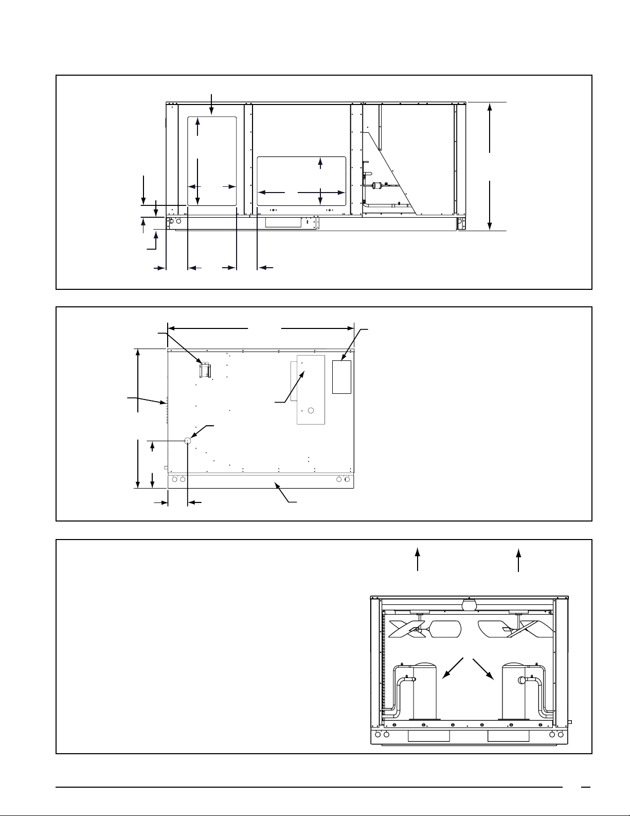
Page 3

Model R6GP-120C235C Shown
Condenser Fan
Assemblies
High/Low
Pressure Switch
Protection
Liquid Line
Filter Driers
High Efficiency
Compressors
with Crankcase
Heaters
Belt Drive
Blower Motor
Knockout
for Bottom
Power Entry**
3/4” PVC
Condensate
Drain
Permament Baserail -
No Need for Removal
with Roof Curb
Knockout for
Bottom Power
Entry
Control Wiring Entry
Power Wiring Entry
Condenser Coils
Electrical
Disconnect
Mounting
Panel +
Easy Access
Control Panel
Durable Pre-Coat
Paint
Quick Release
Filter Panel
Evaporator Coils
Exhaust Vent
Gas Line Inlet
Flame
Observation
Combustion
Air Inlet
+ Field Supplied
** Field Installed Kit Required
3
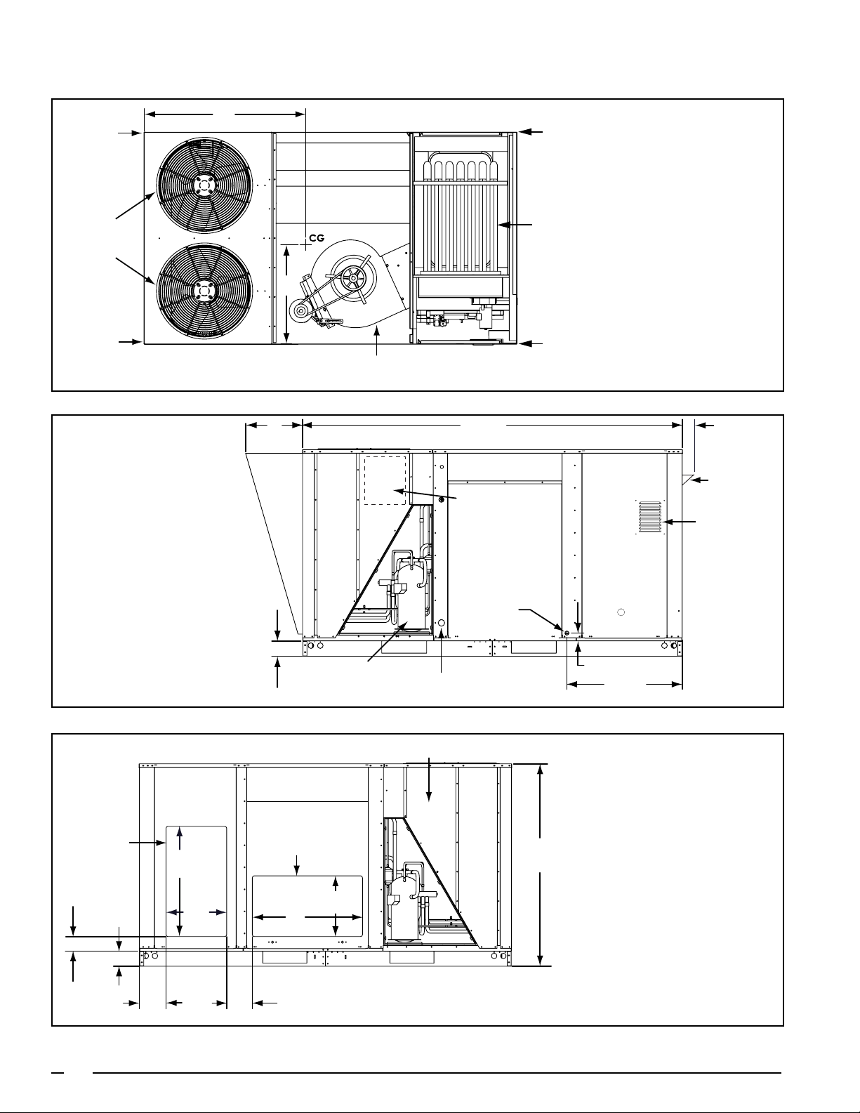
Page 4
R6GP – PHYSICAL DATA
101 1/2
(2578)
2 (51)
30 3/4
4
(102)
FLAME
OBSERVATION
PORT
CONDENSAT E
DRAIN
BOTTOM POWER KIT
MOUNTING LOCATION
4 (102)
INDOOR BLOWER
COMBUSTION
AIR INLET
HIGH VOLTAGE
CONNECTIONS
OUTDOOR
COMPARTMENT
LOW VOLTAGE
CONNECTIONS
GROUND
CONNECTIONS
INDUCER
EXHAUST
RECOMMENDED
DISCONNECT
MOUNTING
LOCATION
Dimensions shown in inches (mm)
A
Corner “D”
Condenser Fans
CG
Corner “A”
Heat
Exchanger
Top View
Corner “C”
Front View
B
Corner weights and
center of gravity
see Table Page 9
Corner “B”
Blower
Assembly
Horizontal Discharge Air Opening*
30
(762)
4
(102)
16 1/2
(419)
4 (102)
7 1/4 (184)
4
Filter Access
Horz. Return Air Opening*
Condenser Coil
16 1/2
(419)
30
(762)
7 (178)
*Shown with optional horizontal duct panels
Physical Dimensions for R6GP-072 Series
43 1/2
(1403)
Rear View
Page 5
R6GP – PHYSICAL DATA (CONTINUED)
INDUCER
Dimensions shown in inches (mm)
EXHAUST
COMBUSTION
AIR LOUVERS
43
(1092)
14 5/8
(371)
57 1/2
(1460)
RECOMMENDED LOCATION
FOR UNIT DISCONNECT
GAS INLET
6 5/64 (154)
UNIT BASERAIL
RATING
LABEL
Heat Exchanger End
Airflow
Airflow
Return Air
Opening
62 (1575)
Condenser End
7 (178)
16 1/2
(419)
30 1/2
(775)
8 3/4
(222)
101 1/4 (2572)
30 1/2
Power
†
Entry
Compressor
7 (178)
5-3/4 (146)
16 1/2
(419)
Bottom Pan Top View
(072, 090, 120)
(775)
Discharge Air
Opening
Physical Dimensions for R6GP-072 Series Continued
5
Page 6
101 1/2
(2578)
16
(406)
2 (51)
30 3/4
(781)
4 (102)
Control Access
Blower Access
Condesate Drain
Field Wiring
(†)Electric Element
Access
Optional
Hail Guard
Hood
4
(102)
Corner “D”
Condenser
Fans
Dimensions shown in inches (mm)
A
CG
B
Corner “A”
Heat
Exchanger
Corner “C”
Top View
Blower
Assembly
Corner “B”
Corner weights and
center of gravity
see Table Page 9
6
Front View
Physical Dimensions for R6GP-090 Series
Page 7
Horizontal Discharge Air Opening
*
INDUCER
*Shown with optional horizontal duct panels
4 (102)
7 1/4 (184)
EXHAUST
COMBUSTION
AIR LOUVERS
4
(102)
43
(1092)
30
(762)
16 1/2
(419)
RECOMMENDED LOCATION
FOR UNIT DISCONNECT
GAS INLET
Horz. Return Air Opening
7 (178)
57 1/2
(1460)
Filter Access
16 1/2
(419)
30
(762)
Condenser Coil
*
43 1/2
(1403)
RATING
LABEL
Heat Exchanger End
Rear View
14 5/8
(371)
6 5/64 (154)
UNIT BASERAIL
Airflow
Airflow
Compressors (x2)
Condenser End
Physical Dimensions for R6GP-090 Series Continued
7
Page 8
A
4
Dimensions shown in inches (mm)
Condenser
Corner “D”
Condenser
Fans
Corner “C”
Front View
B
16
(406)
Optional
Hail Guard
Hood
Filters (x4)
Evaporator
Assembly
Blower
Exchanger
101 1/2
(2578)
Control Access
Recommended Unit
Disconnect Mounting
Location
Blower Access
Corner “A”
Heat
Top View
Corner “B”
(102)
Inducer
Exhaust
Combustion
Air Inlet
Horizontal
Discharge
Air
Opening*
4 (102)
4 (102)
7 1/4 (184)
4 (102)
Compressor
*Shown with optional horizontal duct panels
Exchanger
Access
30
(762)
Heat
16 1/2
(419)
Filter Access
Horiz. Return
Air Opening*
30
(762)
7
(178)
16 1/2
(419)
Condensate
Electric
Supply Entries
Coils
Drain
55 1/4
(1403)
2 (51)
30 3/4
(781)
Rear View
Physical Dimensions for R6GP-120 Series
8
Page 9

18 1/2
(470)
Optional
Fresh Air
Intake
Hood
Optional
Relief
Hood
Airflow
Condenser Coil
Compressors (2)
Airflow
9 7/8 (250)
8 (203)
57 1/2
(1461)
Gas Inlet
4 (102)
Condenser End
Heat Exchanger End
Physical Dimensions for R6GP-120 Series Continued
Model No.
Unit Weight ‡
Lbs. Kg. Lbs. Kg A B Lbs. Kg. Lbs. Kg. Lbs. Kg. Lbs. Kg.
R6GP-072*-100 934 425 1069 486
R6GP-072*-166 959 436 1094 497
R6GP-090*-200 983 446 1118 507
R6GP-120*-235 1301 590 1441 654
* Baserails are not intended to be removed. Information provided is total unit height for horizontal duct applications or height dimension added to selected roof curb
height for vertical duct applications.
‡ Unit weight without packaging or field installed accessories.
Shipping
Weight
Center of Gravity
Inches (mm)
48
(1219)
(1245)
55 3/8
(1407)28(711)
(1245)30(762)
25 5/8
(651)
49
25 5/8
(651)
49
A B C D
197 89 245 111 273 124 219 100
206 94 257 117 275 125 221 100
262 119 275 125 229 104 218 99
300 136 328 149 351 159 322 146
Corner Weights Unit Height*
Horizontal
Duct
Applications
43 1/2
(1105)
43 1/2
(1105)
43 1/2
(1105)
55-1/4
(1409)
Applications
Vertical
Duct
38 1/4
(972)
38 1/4
(972)
38 1/4
(972)
51
(1295)
Center of Gravity & Unit Shipping Weights
MODEL IDENTIFICATION CODE
R 6 G P - 090 C 045 C A
Application
R = Rooftop Packaged Unit
Series
Gas
P = 11.0 - 11.9 EER
Cooling
Nominal
Capacity
(000) Btu
Revision
C = U.S./Canada - Aluminized Steel Hx
S = U.S./Canada - Stainless Steel Hx
Heating Capacity
(000) Btu
Electrical Code
C = 208/230-60-3
D = 460-60-3
9
Page 10
PHYSICAL SPECIFICATIONS DATA
Model R6GP- 072(C/D) 090(C/D) 120(C/D)
Nominal Capacity (tons) 6 7.5 10.0
Performance Data
Total Gross Cooling Capacity (Btuh) 73,300 93,500 125,000
Rated Net Cooling Capacity (Btuh) 72,000 90,000 119,000
E.E.R. - Cooling Efficiency (Btuh/Watt) 11.2 11.2 11.2
IEER - Part load Efficiency 12.6 12.3 11.5
Rated Airflow - CFM 2,400 3,000 4,000
Compressor Data
Compressor(s) Type Scroll Scroll Scroll
Quantity (number of refrigeration circuits) 1 2 2
Unit Capacity Steps (%) 100 50/50 50/50
Crankcase Heaters yes yes yes
POE Oil Charge (Ea.) 56 Oz. 42 Oz. 42 Oz.
Refrigerant Charge (R-410a)
Stage 1 Circuit 240 Oz. 168 Oz. 216 Oz.
Stage 2 Circuit - 168 Oz. 216 Oz.
System Pressure Switches
Manual Reset High Pressure Switch (PSIG) Cut Out: 650 +/- 10
Loss of Charge Switch (PSIG) Cut Out: 5 +/- 5, Cut In: 20 +/- 5
Outdoor Fan Data
Fan Diameter / Total Nominal CFM 20” / 7000 24” / 8200 24” / 8200
Motor - HP / RPM 1/3 - 1100 1/3 - 1075 1/3 - 1075
Quantity 2 2 2
Outdoor Coil Data
Rows / fpi 2 / 18 2 / 19 2 / 17
Type Cu Tube/Al Fin Cu Tube/Al Fin Cu Tube/Al Fin
Total Face Area (sq ft) 17.0 25.5 34.0
Indoor Coil Data
Rows / fpi 4 / 14 4 / 14 4 / 14
Type Cu Tube/Al Fin Cu Tube/Al Fin Cu Tube/Al Fin
Total Face Area (sq ft) 8.5 8.5 11.3
Expansion Device TXV TXV TXV
Freeze Protection Thermostat Opens (˚F): 28 +/- 5, Closes (˚F): 57 +/- 6
Indoor Blower Data
Blower Type Centrifugal Centrifugal Centrifugal
(Qty.) - Wheel Diameter (1) - 12 x 12 (1) - 12 x 12 (1) - 15 x 15
Drive Type Belt Belt Belt
Standard Blower Drive Motor 4
Motor - Hp / RPM 1 / 1725 1.5 / 1750 2/1800
Speeds 1 1 1
Frame Size 143T 143T 143T
NEMA Efficiency Premium Eff. Premium Eff. Premium Eff.
Blower RPM Range 715 - 971 777 - 1060 672 - 897
Blower ESP Range (in-WC) 0.1 - 1.0 0.1 - 1.3 0.1 - 1.0
Installed Filters
Style Disposable - 2” Pleated
Size[inches] (Qty.) 16x20 (4) 16x20 (4) 16x25 (4)
Sound Rating Number dBA
Notes:
1) Certified in accordance with AHRI Standard 340/360 at the rated airflow shown and the minimum external static duct pressure allowed by the standard. ARI Rating for
units with dual voltages are shown at highest rated unit voltage.
2) E.E.R. - Energy Efficiency Ratio: The EER and Net Capacity is determined @ 95˚F Outdoor DB and with air entering the evaporator at 80˚F DB / 67˚F WB
3) IEER - Intergrated Energy Efficiency Ratio: a measure of merit for part load performance of the unit.
4) Refer to Alternate Accessory Drive Table for other available motor/drive kits
1,2,3
83.5 85.2 85.8
10
Page 11

UNIT HEATING PERFORMANCE DATA
Model R6GP- 072(C/D) 090(C/D) 120(C/D)
Heater Model -100(c,s) -166(c,s) -200(c,s)a -235(c,s)b
High Heating Input (Btuh)
High Heating Output (Btuh) 80,000 132,800 160,000 188,000
Low Heating Input (Btuh)
Low Heating Output (Btuh) 52,000 86,400 104,000 120,000
Steady State Efficiency 80% 80% 80% 80%
Number of Capacity Stages 2 2 2 2
Ignition Type Spark Spark Spark Spark
Number of Burners 3 5 6 7
Gas Piping Connection (in) 1/2” NPT 1/2” NPT 1/2” NPT 3/4” NPT
Factory Configured
Notes:
1) Units with Heating inputs of 225,000 Btuh or greater are rated in accordance with DOE 10 CFR Part 431
2) Capacities shown represent use with Natural Gas, refer to Table 10 for LP gas capacities
3) Heat Exchangers are convertible to LP with Accessory Kit
1, 2
1, 2
3
100,000 166,000 200,000 235,000
65,000 108,000 130,000 150,000
Nat. Gas Nat. Gas Nat. Gas Nat. Gas
TEMPERATURE RISE/AIRFLOW
Heating
Unit
Model
R6GP-072*-100
R6GP-072*-166
R6GP-090*-200
R6GP-120*-235
* At Elevations of 2000 Ft or less
Gas
Type
Heating
Input
Heating
Output
Rise
Range CFM Range
SCFM 1950 2100 2250 2400 2550 2700
Natural Gas 100,000 80,000
Propane (LP) 85,000 68,000 32 30 28 26 25 23
15 - 45
Rise (ºF)*
38 35 33 31 29 27
SCFM 1950 2100 2250 2400 2550 2700
Natural Gas 166,000 133,000
Propane (LP) 141,000 112,800 54 50 46 44 41 39
35 - 65
Rise (ºF)*
63 59 55 51 48 46
SCFM 2425 2625 2800 3000 3188 3375
Natural Gas 200,000 160,000
Propane (LP) 175,000 140,000 53 49 46 43 41 38
30 - 60
Rise (ºF)*
61 56 53 49 46 44
SCFM 3250 3500 3750 4000 4250 4500
Natural Gas 235,000 188,000
Propane (LP) 205,000 164,000 47 43 40 38 36 34
25 - 55
Rise (ºF)*
54 50 46 44 41 39
ORIFICE OR DRILL SIZE FOR NATURAL AND PROPANE (LP) GASES.
Unit
Model
R6GP-072*-100
R6GP-072*-166
R6GP-090*-200
R6GP-120*-235
* Refer to Instructions for High Altitude Deration to determine heat-exchanger capacity at increased elevations.
Gas
Type
Natural Gas 100,000
Propane (LP) 85,000 53 54 54 55 55
Natural Gas 166,000
Propane (LP) 141,000 53 54 54 55 55
Natural Gas 200,000
Propane (LP) 175,000 51 52 52 52 53
Natural Gas 235,000
Propane (LP) 205,000 51 52 52 52 53
Heating
Input
Number
of
Burners
3
5
6
7
0-2,000 Ft 2,001-4,000 Ft 4,001-6,000 Ft 6,001-8,000 Ft 8,001-10,000 Ft
36 38 40 41 43
36 38 40 41 43
36 38 40 41 43
36 38 40 41 43
Table 10. Approximate Orifice or Drill Size for Natural and Propane (LP) Gases.
Orifice Size for Increased Elevation*
(Above Sea Level)
11
Page 12
ELECTRICAL DATA FOR POWER EXHAUST ACCESSORY KITS
Part #
Model
† Volts HP CFM FLA Fuse MCA MOP
R6GP-072 & 090 547867 230 1/2 2350 3.00 6A 3.75 6.75
R6GP-072 & 090 547868 460 1/2 2350 1.50 3A 1.88 3.38
R6GP-120 547876 230 3/4 4900 4.00 9A 5.00 9.00
R6GP-120 547877 460 3/4 4900 2.00 4A 2.50 4.50
† See Accessory List, pg 22
ELECTRICAL DATA
Outdoor
motors
(2) ea.
Indoor
Motor
4
Inducer Motor
Total Unit
RLA Unit Only Circuit
Model Number
Nominal Unit
2,3
Voltage
1
Compressors
Factory Unit Electrical Data:
R6GP QTY RLA LRA FLA Hp FLA Hp FLA LRA FLA MCA MOP
-072-(100/166) 208-230 V 1 ea. 19 123 1.5
-072-(100/166) 460 V 1 ea. 9.7 62 0.8 1.5 12.8 16 20
-090-200 208-230 V 2 ea. 13.1 83.1 2.3
-090-200 460 V 2 ea. 6.1 41 1.2 2.1 16.7 19 20
-120-235 208-230 V 2 ea. 16.0 110 2.3
-120-235 460 V 2 ea. 7.8 52 1.2 2.9 20.9 23 30
Notes:
1) To achieve the rated unit performance, unit voltage should be within 2% of
nominal.
2) For C series units:
Nominal Unit Input Voltage = 208-230 Volt, 60 Hertz, 3 Phase
Minimum allowed unit voltage = 187V
Maximum allowed voltage = 253V
3) For D series units:
Nominal Unit Input Voltage = 460 Volt, 60 Hertz, 3 Phase
Minimum allowed unit voltage = 414V
Maximum allowed voltage = 506V
4) Indoor Motors meet 2010 DOE requirements (Premium Efficient)
5) FLA = Full Load Amps MCA = Minimum Circuit Ampacity
RLA = Rated Load Amps MOP = Maximum Over-Current Protection
LRA = Locked Rotor Amps
1.5
3.2-3.1
1
4.4-4.2
6.0-5.8
2
1/12 0.5 0.76
1/12 0.5 0.76
1/12 0.5 0.76
25.2 30-30 45-45
35.2 39-39 50-50
42.6 47-47 60-60
12
Page 13
R6GP - EXPANDED RATINGS, COOLING MODE
R6GP-072-(100/166)
O.D.T 85°F 95°F 105°F 115°F
CFM E.D.B. E.W.B. T.C. S.C. kW T.C. S.C. kW T.C. S.C. kW T.C. S.C. kW
62 68.4 52.3 5.64 63.1 49.9 6.24 57.7 47.6 6.85 52.4 45.2 7.46
75
2250
80
75
2400
80
75
2550
80
67 76.1 41.1 5.73 70.6 39.0 6.33 65.0 36.8 6.92 59.5 34.7 7.52
72 84.7 32.3 5.82 78.7 30.2 6.41 72.8 28.2 7.01 66.8 26.1 7.60
62 68.7 63.0 5.65 63.7 60.5 6.21 58.6 57.9 6.78 54.4 54.2 7.47
67 76.1 52.3 5.74 71.4 50.3 6.28 66.7 48.2 6.83 60.7 45.5 7.54
72 84.1 41.5 5.85 78.8 39.4 6.37 73.4 37.2 6.89 67.0 34.5 7.55
62 69.2 54.2 5.73 63.9 51.7 6.34 58.6 49.3 6.95 53.3 46.8 7.55
67 77.1 42.4 5.81 71.6 40.0 6.41 66.2 37.6 7.01 60.7 35.2 7.61
72 85.9 32.3 5.92 79.9 30.5 6.51 73.8 28.7 7.10 67.8 26.9 7.70
62 69.7 64.4 5.75 65.1 61.4 6.35 60.5 58.5 6.95 55.9 55.6 7.55
67 77.0 54.1 5.82
72 85.1 42.7 5.92 79.5 40.3 6.50 73.9 37.9 7.09 68.2 35.5 7.67
62 70.0 56.0 5.82 64.7 53.5 6.43 59.5 50.9 7.04 54.2 48.4 7.65
67 78.0 43.7 5.89 72.7 41.0 6.50 67.3 38.4 7.10 61.9 35.7 7.71
72 87.0 32.2 6.01 81.0 30.7 6.61 74.9 29.1 7.20 68.8 27.6 7.79
62 70.6 65.8 5.85 66.2 62.8 6.45 62.5 60.9 6.97 57.3 56.9 7.63
67 77.9 56.0 5.90 72.6 53.4 6.50 67.4 50.9 7.11 62.2 48.3 7.71
72 86.1 43.9 5.98 80.6 41.4 6.59 75.0 38.9 7.19 69.5 36.4 7.79
72.0 51.7 6.43
65.9 49.4 7.08 60.4 47.0 7.71
R6GP-072-(100/166)
O.D.T 55°F 65°F 75°F 85°F
CFM E.D.B. E.W.B. T.C. S.C. kW T.C. S.C. kW T.C. S.C. kW T.C. S.C. kW
62 78.6 57.9 4.49 75.2 56.0 4.87 71.8 54.2 5.25 68.4 52.3 5.64
75
2250
80
75
2400
80
75
2550
80
Notes:
1) T.C. = Total (Net) Cooling Capacity, S.C. = Sensible Cooling Capacity, kW = Kilowatts
2) Expanded Ratings are based on 230 Volt - 60 Hz operation
3) Ratings based on Factory Standard Blower Drive
4) Bolded Values indicate ARI rating points
5) Energy Efficiency Ratio (EER) = T.C. / kW
67 86.8 46.7 4.59 83.2 44.8 4.97 79.7 43.0 5.35 76.1 41.1 5.73
72 95.0 36.1 4.70 91.6 34.8 5.07 88.1 33.6 5.45 84.7 32.3 5.82
62 79.2 68.9 4.47 75.8 66.9 4.85 72.8 65.5 5.21 68.7 63.0 5.65
67 87.3 58.2 4.57 83.8 56.3 4.95 80.6 54.9 5.31 76.1 52.3 5.74
72 95.0 45.6 4.69 91.6 44.3 5.06 88.8 43.5 5.41 84.1 41.5 5.85
62 79.6 59.7 4.58 76.1 57.8 4.97 72.6 56.0 5.35 69.2 54.2 5.73
67 87.6 48.0 4.68 84.1 46.1 5.06 80.6 44.3 5.44 77.1 42.4 5.81
72 95.6 36.0 4.79 92.4 34.8
62 80.2 70.6 4.57 76.7 68.7 4.95 73.6 67.3 5.31 69.7 64.4 5.75
67 88.1 59.5 4.66 84.6 57.6 5.03 81.5 56.2 5.39 77.0 54.1 5.82
72 95.6 45.5 4.78 92.4 44.2 5.15 89.8 43.4 5.50 85.1 42.7 5.92
62 80.5 61.5 4.68 77.0 59.6 5.06 73.5 57.8 5.44 70.0 56.0 5.82
67 88.3 49.3 4.77 84.9 47.4 5.15 81.5 45.6 5.52 78.0 43.7 5.89
72 96.2 35.9 4.88 93.1 34.7 5.26 90.1 33.4 5.64 87.0 32.2 6.01
62 81.1 72.4 4.66 77.6 70.5 5.04 74.5 69.2 5.40 70.6 65.8 5.85
67 88.8 60.8 4.75 85.5 58.9 5.12 82.4 57.5 5.48 77.9 56.0 5.90
72 96.2 45.4 4.88 93.2 44.1 5.24 90.8 43.4 5.60 86.1 43.9 5.98
5.17 89.1 33.5 5.54 85.9 32.3 5.92
13
Page 14

R6GP - EXPANDED RATINGS, COOLING MODE
R6GP-090 (Two Compressor Operation)
O.D.T 85°F 95°F 105°F 115°F
CFM E.D.B. E.W.B. T.C. S.C. K.W. T.C. S.C. K.W. T.C. S.C. K.W. T.C. S.C. K.W.
62 85.3 65.2 7.08 81.3 63.9 7.74 73.4 62.7 8.84 68.5 61.2 9.39
75
2825
80
75
3000
80
75
3188
80
67 93.3 52.4 7.19 88.8 51.2 7.84 80.1 50.0 8.94 74.8 48.6 9.46
72 101.9 39.3 7.31 97.3 38.0 7.97 87.7 36.7 9.06 82.0 35.3 9.59
62 86.0 76.5 7.09 82.2 75.5 7.75 74.3 74.5 8.85 69.8 73.6 9.40
67 92.9 64.4 7.18 88.6 63.4 7.84 80.0 62.4 8.94 74.7 61.2 9.46
72 101.7 51.4 7.31 97.0 50.4 7.96 87.5 49.3 9.06 81.6 48.1 9.58
62 86.8 69.4 7.27 82.7 68.1 7.93 74.5 66.8 9.05 69.5 65.3 9.57
67 94.6 55.2 7.38 90.0 54.0 8.03 80.9 52.7 9.14 75.3 51.3 9.64
72 103.5 40.4 7.51 98.6 39.1 8.17 88.8 37.8 9.27 82.9 36.3 9.78
62 87.9 81.9 7.29 84.3 81.8 7.96 76.6 80.3 9.08 72.2 76.4 9.60
67 94.5 68.5 7.38
72 103.1 54.2 7.51 98.2 53.1 8.16 88.4 52.0 9.26 82.5 50.9 9.78
62 87.9 73.3 7.46 83.7 72.0 8.12 75.3 70.7 9.24 70.2 69.1 9.75
67 95.3 57.8 7.57 90.3 56.5 8.22 81.2 55.1 9.32 75.7 53.6 9.82
72 104.6 41.4 7.71 99.5 40.1 8.36 89.6 38.7 9.46 83.5 37.3 9.95
62 90.3 88.4 7.50 86.7 86.3 8.16 78.7 78.3 8.49 74.0 73.7 9.80
67 95.6 72.5 7.57 91.1 71.4 8.23 82.0 70.4 8.56 76.6 69.2 9.83
72 104.1 56.8 7.70 98.9 55.7 8.35 88.9 54.7 8.68 82.4 53.4 9.95
90.0 67.5 8.04
81.2 66.5 9.14 75.6 65.3 9.65
R6GP-090 (One Compressor Operation)
O.D.T 55 °F 65 °F 75 °F 85 °F
CFM E.D.B. E.W.B. T.C. S.C. kW T.C. S.C. kW T.C. S.C. kW T.C. S.C. kW
62 58.5 52.6 3.74 52.5 47.2 3.88 48.0 44.1 4.10 45.0 43.2 4.42
75
2825
80
75
3000
80
75
3190
80
Notes:
1 ) T.C. = total (Net) cooling in kBtuh; S.C. = Sensible Cooling in kBtuh; kW = Kilowatts
2 ) Ratings are based on the Factory Standard blower drive combination
3 ) For 208-230V Units, the ratings shown reflect 230V operation
4 ) Bolded Values indicate AHRI rating points
5 ) Energy Efficiency Ratio (EER) = T.C./kW
67 64.7 44.3 3.81 58.8 38.9 3.95 54.3 35.8 4.18 51.3 34.9 4.49
72 71.7 35.0 3.90
62 59.3 59.3 3.78
67 64.6 57.4 3.85 58.7 52.0 3.98 54.2 48.9 4.21 51.1 48.0 4.52
72 70.5 49.5 3.92 64.6 44.1 4.06 60.1 41.0 4.28 57.0 40.1 4.59
62 59.0 53.7 3.77 53.1 48.3 3.91 48.6 45.2 4.14 45.5 44.3 4.45
67 65.3 45.3 3.85 59.4 40.0 3.99 54.9 36.9 4.21 51.8 36.0 4.53
72 72.2 36.1 3.93 66.3 30.8 4.07 61.8 27.6 4.30 58.8 26.8 4.61
62 59.8 59.8 3.82 53.9 53.9 3.96 49.4 49.4 4.18 46.3 46.3 4.49
67 65.1 58.4 3.88 59.2 53.1 4.02 54.7 50.0 4.24 51.6 49.1 4.56
72 71.1 50.6 3.95 65.1 45.2 4.09 60.6 42.1 4.32 57.6 41.2 4.63
62 59.5 55.3 3.77 53.6 50.0 3.90 49.1 46.8 4.13 46.0 46.0 4.44
67 65.8 47.0 3.84 59.8 41.6 3.98 55.3 38.5 4.20 52.3 37.6 4.52
72 72.7 37.8 3.92 66.8 32.4 4.06 62.3 29.3 4.29 59.2 28.4 4.60
62 60.3 60.3 3.81 54.4 54.4 3.95 49.9 49.9 4.17 46.8 46.8 4.49
67 65.6 60.1 3.87 59.7 54.7 4.01 55.2 51.6 4.24 52.1 50.7 4.55
72 71.5 52.2 3.94 65.6 46.9 4.08 61.1 43.7 4.31 58.0 42.9 4.62
65.8
53.3
29.7 4.04 61.3 26.6 4.26 58.2 25.7 4.57
53.3 3.92 48.8 48.8 4.15 45.8 45.8 4.46
14
Page 15

R6GP - EXPANDED RATINGS, COOLING MODE
R6GP-120 (Two Compressor Operation)
O.D.T 85°F 95°F 105°F 115°F
CFM E.D.B. E.W.B. T.C. S.C. K.W. T.C. S.C. K.W. T.C. S.C. K.W. T.C. S.C. K.W.
62 112.7 86.5 9.36 107.5 84.9 10.24 97.0 83.3 11.68 90.5 81.3 12.41
75
3500
80
75
4000
80
75
4500
80
67 123.3 69.6 9.50 117.4 68.0 10.37 105.9 66.3 11.82 98.8 64.5 12.50
72 134.7 52.2 9.67 128.6 50.5 10.53 115.9 48.7 11.98 108.4 46.9 12.68
62 113.7 101.5 9.37 108.6 100.3 10.25 98.2 98.9 11.71 92.3 97.8 12.43
67 122.8 85.5 9.49 117.2 84.2 10.36 105.7 82.8 11.82 98.8 81.3 12.51
72 134.4 68.3 9.67 128.2 66.9 10.53 115.6 65.5 11.98 107.9 63.9 12.67
62 114.8 92.1 9.62 109.3 90.4 10.49 98.5 88.7 11.96 91.8 86.7 12.65
67 125.0 73.3 9.76 118.9 71.6 10.62 107.0 70.0 12.08 99.6 68.1 12.74
72 136.8 53.6 9.93 130.3 51.9 10.80 117.4 50.1 12.25 109.6 48.2 12.93
62 116.2 108.8 9.64 111.5 108.6 10.52 101.3 106.6 12.01 95.4 101.5 12.69
67 124.9 91.0 9.75
72 136.3 71.9 9.93 129.8 70.5 10.79 116.9 69.1 12.25 109.1 67.6 12.92
62 116.2 97.4 9.87 110.7 95.6 10.74 99.6 93.9 12.22 92.8 91.8 12.89
67 125.9 76.8 10.00 119.4 75.0 10.86 107.3 73.2 12.33 100.0 71.2 12.98
72 138.2 55.0 10.19 131.6 53.2 11.05 118.4 51.4 12.51 110.4 49.5 13.16
62 119.4 117.4 9.91 114.6 114.6 10.79 104.0 104.0 11.22 97.8 97.8 12.95
67 126.4 96.2 10.01 120.4 94.9 10.88 108.5 93.5 11.31 101.2 91.9 13.00
72 137.6 75.4 10.18 130.7 74.0 11.04 117.5 72.6 11.48 108.9 70.9 13.16
119.0 89.6 10.62
107.3 88.3 12.09 100.0 86.7 12.75
R6GP-120 (One compressor operation)
O.D.T 55 °F 65 °F 75 °F 85 °F
CFM E.D.B. E.W.B. T.C. S.C. kW T.C. S.C. kW T.C. S.C. kW T.C. S.C. kW
75
3500
4000
4500
Notes:
1 ) T.C. = total (Net) cooling in kBtuh; S.C. = Sensible Cooling in kBtuh; kW = Kilowatts
2 ) Ratings are based on the Factory Standard blower drive combination
3 )For 208-230V Units, the ratings shown reflect 230V operation
4 ) Bolded Values indicate AHRI rating points
5 ) Energy Efficiency Ratio (EER) = T.C./kW
62 65.9 49.1 4.50 61.8 46.9 4.80 56.8 44.3 5.10 50.7 41.4 5.50
67 73.8 37.5 4.70 69.8 35.3 5.00 64.7 32.7 5.30 58.7 29.8 5.70
72 82.6 27.7 4.80 78.6 25.5 5.10 73.5 22.9 5.50 67.5 19.9 5.90
80
62 69.9 58.8 4.30 65.9 56.6 4.60 60.9 54.0 5.00 54.8 51.0 5.30
67 76.7 47.9 4.50 72.6 45.6 4.70 67.6 43.1 5.10 61.5 40.1 5.50
72 84.2 36.5 4.60 80.1 34.3 4.90 75.1 31.7 5.20 69.0 28.8 5.60
75
62 66.9 50.5 4.90 62.9 48.3 5.20 57.9 45.7 5.50 51.8 42.8 5.90
67 74.9 38.8 5.00 70.8 36.5 5.30 65.8 34.0 5.60 59.7 31.0 6.00
72 83.7 28.8 5.20 79.6 26.6 5.40 74.6 24.0 5.80 68.5 21.0 6.20
80
62 68.8 58.9 5.00 64.8 56.7 5.20 59.8 54.1 5.60 53.7 51.2 6.00
67 75.5 48.4 5.10 71.5 46.2 5.30 66.5 43.6 5.70 60.4 40.7 6.10
72 83.0 37.5 5.20 79.0 35.3 5.40 74.0 32.7 5.80 67.9 29.7 6.20
75
62 68.0 51.9 5.20 64.0 49.7 5.50 58.9 47.1 5.80 52.9 44.2 6.20
67 75.9 40.0 5.40 71.9 37.8 5.60 66.9 35.2 6.00 60.8 32.2 6.40
72 84.7 29.9 5.50 80.7 27.7 5.80 75.7 25.1 6.10 69.6 22.1 6.50
80
62 67.9 59.0 5.60 63.9 56.8 5.90 58.9 54.2 6.20 52.8 51.3 6.60
67 74.4 49.0 5.70 70.4 46.7 5.90 65.4 44.1 6.30 59.3 41.2 6.70
72 82.3 38.1 5.70 78.2 35.9 6.00 73.2 33.3 6.30 67.1 30.3 6.70
15
Page 16

BLOWER PERFORMANCE DATA
R6GP-072-100
Factory Standard: 1 Hp Down-flow Performance Chart
Extended
Unit Static
(in-Wg)
0.1
0.2
0.3
0.4
0.5
0.6
0.7
0.8
0.9
1.0
Operating
@ 230 or
460 Volts
CFM
RPM
kW
CFM
RPM
kW
CFM
RPM
kW
CFM
RPM
kW
CFM
RPM
kW
CFM
RPM
kW
CFM
RPM
kW
CFM
RPM
kW
CFM
RPM
kW
CFM
RPM
kW
Fully
Closed
1/2 Turn
Open
1 Turn
Open
1.5 Turns
2528 2301 2074
936 912 888 866
0.97 0.86 0.76
2417 2220 2111
960 940 908
1.02 0.85 0.79
2105 1854
964 944
0.88 0.77
Open
2582 2399 2177
908 884 862 866
0.98 0.86 0.76
2588
Indicates a recommended
719
unit operational point
0.72
2793
715
0.77
Indicates a setting that is not permitted for unit operation
Adjustable Motor Sheave Setting
2 Turns
Open
2.5 Turns
Open
3 Turns
Open
2975 2828
824 800 775 749 722
0.98
2763
828 804 760 746 726
0.95
3.5 Turns
Open
0.88
2608 2453 2293 2110
0.84 0.72 0.63 0.57
2727 2582 2381 2180 1982
854 831 808 784 750
0.95 0.86 0.75 0.65 0.56
2680 2488 2295 2105
880 858 835 801 786
0.97 0.86 0.76 0.63
1913
0.68
1913
0.68
Indicates an allowable setting that is
not recommended for unit operation †
† These operational points should be carefully examined
by the installer for proper unit setup and heating operation
‡ Indicates Factory Sheave Setting
4 Turns
Open
2867 2728
771 745 719
0.85 0.78
2680 2528 2375
0.79 0.72 0.65
1860
0.54
4.5 Turns
Open
2946 2793
741 715
0.85
5 Turns
Open ‡
0.77
2588
0.72
R6GP-072-100
Factory Standard: 1 Hp Horizontal Performance Chart
Extended
Unit Static
(in-Wg)
0.1
0.2
0.3
0.4
0.5
0.6
0.7
0.8
0.9
1.0
Operating
@ 230 or
460 Volts
CFM
RPM
kW
CFM
RPM
kW
CFM
RPM
kW
CFM
RPM
kW
CFM
RPM
kW
CFM
RPM
kW
CFM
RPM
kW
CFM
RPM
kW
CFM
RPM
kW
CFM
RPM
kW
Fully
Closed
1/2 Turn
Open
1 Turn
Open
1.5 Turns
2545 2353 2100
931 907 833 858
1.02 0.91 0.78
2414 2306 2046
959 936 912
1.04 0.92 0.79
2174 2013
964 941
0.90 0.81
Open
2563 2349 2165
903 879 855 833
1.00 0.87 0.77
‡ Indicates Factory Sheave Setting
Adjustable Motor Sheave Setting
2 Turns
Open
2626 2462 2298 2026
877 853 829 800 775
0.99 0.87 0.76 0.64
2.5 Turns
Open
3 Turns
Open
2812
821 795 769 745 721
0.96
3.5 Turns
Open
2881
792 766 745 723
0.92
2663 2514 2289 2085
0.85 0.74 0.68 0.56
2729 2590 2426 2261
850 826 799 772 746
0.97 0.85 0.77 0.68
2018
0.68
1862
0.68
4 Turns
Open
2955 2785
764 742 720
0.88 0.79
4.5 Turns
Open
2999 2848
740 717
0.86
5 Turns
Open ‡
2615
2738 2558 2377
0.81 0.72 0.64
1995
0.60
1957
0.58
0.76
0.69
1802
730
0.46
Values includes losses for: Unit Casing, 2" Disposable (Pleated) Filters & Dry Evaporator Coil
For approximate Cfm at 208V Deduct 0.5%
16
Page 17

BLOWER PERFORMANCE DATA
R6GP-072-166
Factory Standard: 1 Hp Down-flow Performance Chart
Extended
Unit Static
(in-Wg)
0.1
0.2
0.3
0.4
0.5
0.6
0.7
0.8
0.9
1.0
Operating
@ 230 or
460 Volts
CFM
RPM
kW
CFM
RPM
kW
CFM
RPM
kW
CFM
RPM
kW
CFM
RPM
kW
CFM
RPM
kW
CFM
RPM
kW
CFM
RPM
kW
CFM
RPM
kW
CFM
RPM
kW
Fully
Closed
1/2 Turn
Open
1 Turn
Open
1.5 Turns
2525 2323 2120
937 915 892 868
1.01 0.89 0.77
2449 2216 2004
964 941 919
1.01 0.88 0.79
2160
971 946
0.92
1928
0.81
Open
2625 2395 2220
909 887 864 840
1.01 0.86 0.78
‡ Indicates Factory Sheave Setting
Adjustable Motor Sheave Setting
2 Turns
Open
2769
881 860 838 811 784
1.04
2.5 Turns
Open
2826
857 834 808 782 756
0.99
3 Turns
Open
2879
831 804 777 753 726
0.96
3.5 Turns
Open
2936 2788
802 776 751 725
0.94 0.85
2708 2537 2335 2132
0.87 0.79 0.68 0.57
2647 2437 2227
0.87 0.78 0.68
2544 2318 2107
0.90 0.77 0.67
2044
0.70
1920
0.68
4 Turns
Open
2989 2832
775 749 722
0.92
4.5 Turns
Open
3025 2872
721 719
0.88
0.83
5 Turns
Open ‡
2613 2437
0.76 0.68
2016
0.59
1895
0.57
0.80
2674
0.74
R6GP-072-166
Factory Standard: 1 Hp Horizontal Performance Chart
Extended
Unit Static
(in-Wg)
0.1
0.2
0.3
0.4
0.5
0.6
0.7
0.8
0.9
1.0
Operating
@ 230 or
460 Volts
CFM
RPM
kW
CFM
RPM
kW
CFM
RPM
kW
CFM
RPM
kW
CFM
RPM
kW
CFM
RPM
kW
CFM
RPM
kW
CFM
RPM
kW
CFM
RPM
kW
CFM
RPM
kW
Fully
Closed
1/2 Turn
Open
2254 2043
971 945
0.96 0.85
1 Turn
Open
1.5 Turns
Open
2668 2474 2285 2095
912 888 865 842
1.05 0.92 0.80 0.69
2572 2386 2200
939 971 894 870
1.07 0.93 0.79
2303 2097
942 920
0.95 0.83
‡ Indicates Factory Sheave Setting
Adjustable Motor Sheave Setting
2 Turns
Open
2745
884 862 839 813 789
1.02
2.5 Turns
Open
3 Turns
3.5 Turns
Open
2879
833 807 781 757 732
0.97
2655 2457 2259
837 811 785 760
0.89 0.78 0.67
2569 2392 2169
0.89 0.77 0.59
1988
0.70
Open
2704 2529 2366 2203
0.86 0.75 0.68 0.60
4 Turns
Open
2771
778 755 731
0.84
4.5 Turns
Open
2620 2469
0.75 0.66
5 Turns
Open ‡
2060
0.59
1946
0.60
2914
724
0.80
2703
728
0.74
Values includes losses for: Unit Casing, 2" Disposable (Pleated) Filters & Dry Evaporator Coil
For approximate Cfm at 208V Deduct 0.5%
17
Page 18

BLOWER PERFORMANCE DATA
R6GP-090-200
Factory Standard: 1 Hp Down-flow Performance Chart
Extended
Unit Static
(in-Wg)
0.1
0.2
0.3
0.4
0.5
0.6
0.7
0.8
0.9
1.0
1.1
1.2
1.3
Operating
@ 230 or
460 Volts
CFM
RPM 867 843
kW
CFM
RPM 893 870
kW
CFM
RPM 895
kW
CFM
RPM 918
kW
CFM
RPM 943
kW
CFM
RPM 968
kW
CFM
RPM 993
kW
CFM
RPM 1010
kW
CFM
RPM
kW
CFM
RPM 1039
kW
CFM
RPM 1043
kW
CFM
RPM
kW
CFM
RPM
kW
Fully
Closed
2904
1.40
2693
1.30
1/2 Turn
Open
3164
1 Turn
Open
3255
1.54
3059 2903 2747
996 974 952 931
1.52
1.44 1.31 1.19
2962 2830
1014 1001 979
1.39 1.31
2754
2572
1018 1005
1.28
1.19
2528
1024
1.17
1.5
3312
2 Turns
Open
3332
1.49
3195 3039 2883 2727
Turns
Open
946 924 902 881 860
1.52
1.40 1.29 1.19 1.07
3128 3001 2825
971 949 927 905
1.42 1.31 1.19
2669
1.20
2508
956
1.08
Adjustable Motor Sheave Setting
2.5
Turns
Open
3 Turns
Open
3613 3496
3.5
Turns
Open
4 Turns
Open
3666 3549
1.49
1.36
3378 3316 3253 3137 3021
846 834 822 800 778
1.52
3439
1.40
1.28 1.25 1.21 1.11 1.01
3315 3190 3135 3080 2946 2811
872 849 836 823 802 780
3384
1.45
3267 3139 3010 2945 2879 2736
1.33 1.20 1.17 1.13 1.03 0.94
896 875 853 839 824 803 782
1.48
1.37 1.25 1.12 1.09 1.06 0.96
3213 3094 2943 2791
921 898 878 857 842
1.38 1.28 1.16 1.05
2571
0.95
2648
1.08
2469
885
0.97
2574
1.09
‡ Indicates Factory Sheave Setting
4.5
Turns
Open
5 Turns
Open ‡
5.5 Turns
Open
3495 3441 3325
832 820 799 777
1.33 1.29 1.18
2726
1.01
2479
845
0.92
2661 2503
826 805
0.98 0.88
6 Turns
Open
3209
1.07
2592
0.86
Values includes losses for: Unit Casing, 2" Disposable (Pleated) Filters & Dry Evaporator Coil
For approximate Cfm at 208V Deduct 0.5%
18
Page 19

BLOWER PERFORMANCE DATA
R6GP-120-235
Factory Standard: 2Hp Down-flow Performance Chart ‡ Indicates Factory Sheave Setting for Pre-configured Units
External
Unit
Static
(in-Wg)
0.1
0.2
0.3
0.4
0.5
0.6
0.7
0.8
0.9
1.0
1.1
1.2
1.3
1.4
Operat-
ing @
230 or
460
Volts
CFM 5061 4896 4731 4558 4384
RPM 736 715 694 673 651
kW 1.86 1.72 1.57 1.44 1.31
CFM 4849 4679 4508 4321 4134
RPM 737 716 696 674 653
kW 1.77 1.63 1.49 1.35 1.22
CFM 5005 4816 4627 4447 4267 4071 3875
RPM 781 760 738 718 697 676 655
kW 2.01 1.83 1.66 1.52 1.38 1.25 1.12
CFM 4773 4593 4413 4202 3990 3777 3564
RPM 782 762 741 720 698 678 657
kW 1.92 1.74 1.56 1.42 1.29 1.15 1.02
CFM 4719 4534 4336 4137 3923 3708 3477 3245
RPM 803 783 764 744 722 699 679 659
kW 1.98 1.79 1.61 1.43 1.30 1.18 1.05 0.92
CFM 4685 4479 4273 4059 3845 3603 3361
RPM 826 806 786 766 746 724 703
kW 2.04 1.85 1.66 1.50 1.33 1.19 1.05
CFM 4457 4236 4014 3773 3531 3243
RPM 828 808 788 768 747 727
kW 1.91 1.72 1.54 1.37 1.20 1.06
CFM 4601 4395 4188 3940 3692 3412
RPM 867 849 832 811 791 771
kW 2.15 1.97 1.78 1.59 1.40 1.22
CFM 4326 4110 3893 3609 3325
RPM 870 853 835 814 793
kW 2.01 1.82 1.63 1.44 1.26
CFM 4251 3998 3765 3531 3252
RPM 890 872 855 839 817
kW 2.03 1.82 1.64 1.45 1.28
CFM 3917 3675 3434 3192
RPM 894 874 858 842
kW 1.83 1.66 1.48 1.31
CFM 3845 3605 3358
RPM 910 897 878
kW 1.89 1.68 1.51
CFM 3551 3274
RPM 913 900
kW 1.73 1.53
CFM 3168
RPM 916
kW 1.56
Fully
Closed
1/2 Turn
Open
1 Turn
Open
1.5
Turns
Open
Adjustable Motor Sheave Setting
2 Turns
Open
2.5
Turns
Open
3 Turns
Open
3.5
Turns
Open
4 Turns
Open
4.5
Turns
Open
5 Turns
Open ‡
5.5
Turns
Open
6 Turns
Open
Values includes losses for: Unit Casing, 2" Disposable (Pleated) Filters & Dry Evaporator Coil
For approximate Cfm at 208V Deduct 0.5%
19
Page 20

BLOWER PERFORMANCE DATA
R6GP-120-235
Factory Standard: 2Hp Horizontal Performance Chart ‡ Indicates Factory Sheave Setting for Pre-configured Units
External
Unit Static
(in-Wg)
0.1
0.2
0.3
0.4
0.5
0.6
0.7
0.8
0.9
1.0
1.1
1.2
1.3
1.4
Operating
@ 230 or
460 Volts
CFM 5020 4871 4722 4536 4350
RPM 736 717 697 675 653
kW 1.82 1.68 1.53 1.41 1.29
CFM 4783 4619 4454 4271 4087
RPM 738 718 698 676 655
kW 1.73 1.59 1.45 1.33 1.20
CFM 4986 4785 4584 4407 4229 4030 3831
RPM 779 760 740 720 699 678 656
kW 2.00 1.82 1.64 1.50 1.36 1.24 1.12
CFM 4720 4519 4317 4120 3922 3727 3532
RPM 783 762 742 722 701 680 659
kW 1.90 1.71 1.53 1.39 1.26 1.14 1.02
CFM 4661 4458 4265 4072 3858 3643 3436 3229
RPM 805 786 765 744 724 703 682 661
kW 1.94 1.76 1.59 1.42 1.29 1.15 1.04 0.92
CFM 4637 4445 4252 4037 3821 3569 3316
RPM 827 808 789 767 746 726 706
kW 1.99 1.82 1.64 1.48 1.32 1.18 1.05
CFM 4394 4191 3988 3745 3502 3238
RPM 830 811 792 770 747 728
kW 1.88 1.70 1.53 1.36 1.20 1.06
CFM 4350 4173 3916 3658 3422 3186
RPM 851 833 814 794 773 751
kW 1.93 1.76 1.57 1.39 1.23 1.07
CFM 4254 4058 3861 3601 3341
RPM 870 853 836 816 796
kW 1.97 1.80 1.62 1.44 1.26
CFM 4191 3982 3762 3542 3270
RPM 891 874 856 839 816
kW 1.99 1.81 1.64 1.47 1.30
CFM 3892 3685 3452 3218
RPM 894 877 860 843
kW 1.83 1.65 1.49 1.32
CFM 3861 3572 3362
RPM 913 897 883
kW 1.88 1.68 1.51
CFM 3500 3244
RPM 915 902
kW 1.70 1.52
CFM 3191
RPM 917
kW 1.55
Fully
Closed
1/2 Turn
Open
1 Turn
Open
1.5 Turns
Open
2 Turns
Open
Adjustable Motor Sheave Setting
2.5 Turns
Open
3 Turns
Open
3.5 Turns
Open
4 Turns
Open
4.5 Turns
Open
5 Turns
Open ‡
5.5 Turns
Open
6 Turns
Open
Values includes losses for: Unit Casing, 2” Disposable (Pleated) Filters & Dry Evaporator Coil
For operation at 208V: Deduct approximately 0.5% from Cfm
20
Page 21

ACCESSORIES - 6, 7 1/2 AND 10 TON R6GP
Part # Description Weight 072 090 120
559914 Horizontal Supply & Return Kit 39 X X
547881 Horizontal Supply & Return Kit 49 X
547860 Hinged Roof Curb 8” High - K/D 70 X X X
547861 Hinged Roof Curb 14” High - K/D 125 X X X
547862 Hinged Roof Curb 18” High - K/D 155 X X X
547863 Hinged Roof Curb 24” High - K/D 220 X X X
559411 Hooded Hail Guard 62 n/a X
558857 Hooded Hail Guard 62 X
547864 0-35% Manual Outside Air Damper 30 X X
547874 0-35% Manual Outside Air Damper 41 X
547865 0-35% Motorized Damper - Only (Requires 547864 OR 547874) 15 X X X
559375 Economizer - Modulating w/ Relief, Adapts Horizontal, Enthalpy Control 125 X X
559374 Economizer - Modulating w/ Relief, Adapts Horizontal, Enthalpy Control 181 X
920233 Sensor, Enthalpy, C7400A (For Economizer Differential Enthalpy Control) X X X
547848 CO2 Sensor for economizer control - 4-9v dc X X X
547867 Power Exhaust - Prop (208/230V - 3Ø), Adapts Horizontal See Note 143 X X
547868 Power Exhaust - Prop (460V - 3Ø), Adapts Horizontal See Note 143 X X
547876 Power Exhaust - Prop (208/230V - 3Ø), Adapts Horizontal See Note 152 X
547877 Power Exhaust - Prop (460V - 3Ø), Adapts Horizontal See Note 152 X
547869 20” Supply & Return Transition Round 38 X X
547870 20” Flush Mount Concentric Diffuser Round 154 X X
547871 20” Step Down Concentric Diffuser Round 157 X X
547878 18” x 28” Supply & Return Transition 36 X
547879 18” x 28” Flush Mount Concentric Diffuser 162 X
547880 18” x 28” Step Down Concentric Diffuser 193 X
558863 Duct Smoke Detector Photo Elect. 3 X X X
558866 Duct Smoke Detector, Remote Multi-signal control SSK 451 1 X X X
558864 Smoke Detector Sampling Tube DST3, 2-4 ft. X X X
558865 Smoke Detector Sampling Tube DST5, 4-8 ft. X X X
920463 Low Ambient Kit X X X
920612 Natural Gas - High Altitude Application Kit X X X
920610 LP Gas - Conversion & High Altitude Application Kit X X X
920465 Bottom Power Entry Kit 7 X X
917165 Bottom Power Entry Kit 7 X
920619 Thermostat-3 Stage Heat/2 Stage Cool X X X
920937 Flue Exhaust Extension Kit 10 X X X
Note:
Requires separate branch circuit, see table Electrical Data For Power Exhaust Accessory Kits, page 12.
Accessory Performance Data
R6GP
-072*
&
-090*
-120*
† Pressure drop data are approximate values to allow for use in all design conditions.
‡ The distance the air from the grille travels from the diffuser before it slows down to 50 ft. per minute. All sides open.
Air
Volume
(CFM)
2200 0.08 0.20 0.03 0.15 0.14 0.13 20-24 0.11 17-25
2400 0.10 0.25 0.04 0.16 0.16 0.13 22-27 0.13 18-26
2600 0.12 0.30 0.04 0.20 0.20 0.15 24-29 0.17 19-26
2800 0.14 0.35 0.04 0.25 0.25 0.20 25-30 0.20 20-28
3000 0.16 0.40 0.04 0.30 0.30 0.25 27-33 0.25 21-29
3200 0.18 0.45 0.05 0.40 0.38 0.30 28-35 0.31 22-29
3400 0.20 0.50 0.05 0.50 0.46 0.40 30-37 0.37 22-30
3600 0.22 0.55 0.05 0.60 0.55 0.50 32-39 0.43 23-31
3600 0.12 0.20 0.04 0.35 0.25 0.20 25-33 0.17 22-29
3800 0.13 0.22 0.04 0.40 0.30 0.25 27-35 0.18 22-30
4000 0.14 0.24 0.04 0.45 0.35 0.30 29-37 0.21 24-33
4200 0.16 0.27 0.05 0.50 0.40 0.35 32-40 0.24 26-35
4400 0.18 0.30 0.05 0.55 0.45 0.40 34-42 0.27 28-37
4600 0.20 0.33 0.05 0.60 0.50 0.45 36-44 0.30 30-39
Wet
Evaporator
Coil
Down Flow
Economizer
Horizontal
Economizer
Total Resistance (inches water column) †
Step Down Diffuser System Flush Mount
2 Ends
Open
2 Ends Open
w/1 Side Open
2 Ends Open
w/2 Sides Open
Throw ‡
(Ft)
Diffuser
System
Throw ‡
(Ft)
21
Page 22

22
Page 23

23
Page 24

For complete catalog information including submittals,
energy calculations, dimension drawings, and more go to
www.ReznorHVAC.com or call 800-695-1901.
© 2015 Reznor LLC.
Reznor is registered in at least the United States. All other trademarks are the property of their respective owners.
All rights Reserved. Printed in U.S.A.
268E-0315 Form S-R6GP
Note: In keeping with our policy of continuous
product improvement, we reserve the right to alter,
at any time, the design, construction, dimensions,
weights, etc., of equipment information shown here.
 Loading...