

Page 1
INSTALLATION INSTRUCTIONS FOR
INSTALLATION
INSTRUCTION
ECONOMIZERS USED WITH R4GM 072
P6SD, Q6SD, R6GD 024-060 UNITS
547841
FORM# 599A-0808 (599A-0298)
Recognize this symbol as an indication of Important Safety Information!
547841 Economizer is used for automatic sensor-controlled introduction of outdoor air into the system through an
electro-mechanically controlled damper.
Step 1:
Check for correct number of parts. See list below.
1 - Economizer Assembly w/ Filter
1 - Adaptor Panels (Attached to Economizer)
1 - Wiring Diagram Sticker
1 - Barometric Relief Hood
1 - Mixed Air Sensor (MAS)
1 - Wire Tie
2 - #10 x 16 x ½” Self-Tapping Screws
10 - #10 x 16 x ½” Type A Screws
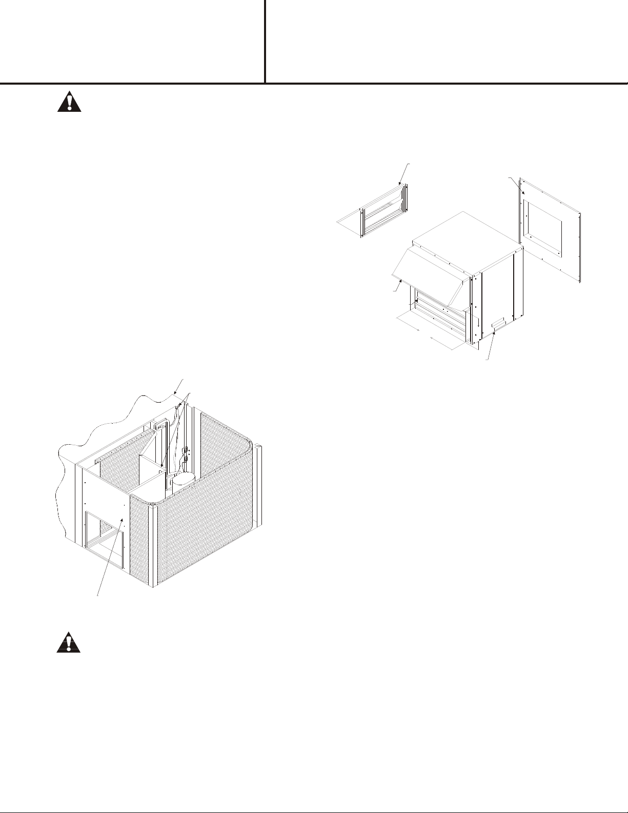
ELECTRICAL ACCESS PANEL
ECONOMIZER WIRE HARNESS ROUTING
FRESH AIR HOOD
RETURN DUCT OPENING
CONTROL AND FILTER ACCESS
BAROMETRIC RELIEF HOOD
ADAPTOR PANEL
24
12
RETURN ACCESS PANEL
WARNING:
Disconnect electrical power to the unit. Failure to do so can cause electrical shock resulting in personal injury or
death.
Step 2:
Take the economizer plug and attach to the unit economizer plug located inside the return air section above the duct
opening. (Factory jumper plug must first be removed.)
Step 3:
Slide Economizer over horizontal return opening of the unit. Secure Economizer using the screws that where provided.
Page 2
INSTALLATION
INSTRUCTION
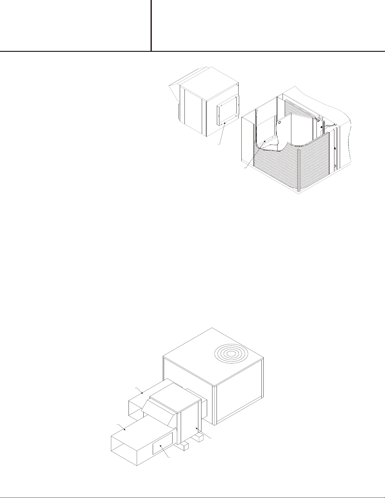
ECONOMIZER DUCT CONNECTION
INSTALLATION INSTRUCTIONS FOR
547841
ECONOMIZERS USED WITH R4GM 072
P6SD, Q6SD, R6GD 024-060 UNITS
UNIT RETURN DUCT CONNECTION
Step 4:
Locate the mixed air sensor (MAS) on the blower deck next to the blower intake opening using the self-tapping screw
provided. Connect MAS to two (2) prewired red wires in blower compartment.
Step 5:
Attach and seal weather tight return duct to Economizer.
Step 6:
If the barometric relief is to be installed cut a 10" x 20" hole in the return air duct near Economizer.
Step 7:
Secure barometric relief damper near Economizer over hole in return air duct using (4) screws provided.
Step 8:
Place the adhesive backed wiring diagram on the electrical access panel by the unit diagram.
SUPPLY DUCT
RETURN DUCT
ECONOMIZER
CUT OPENING 10" X 20"
Page 3

INSTALLATION
INSTRUCTION
INSTALLATION INSTRUCTIONS FOR
547841
ECONOMIZERS USED WITH R4GM 072
P6SD, Q6SD, R6GD 024-060 UNITS
BAROMETRIC RELIEF
Step 9:
Turn power back on to the unit. See the enclosed HoneywellÒ specification data for operation and check out.
SUPERSEDES 10-26-04
SEPTEMBER 2, 2008
NEIHE06
Page 4

HARNESS DETAIL
E# = WIRE END DESIGNATION
E2 STUD #6 18 Ga. Wire
E3 Female ¼ Quick Disc.
E4 Male ¼ Quick Disc. Insul
E6 Wire Nut Size 73B
E7 Raw End
E8 Female
3
Quick Disc.
16
HAR NESS
ENDS AT P1
COMPONENT CODE
C7400A Fresh Air Sensor
M7415A Damper Actuator 24v
C7150C Mixed Air Sensor
W7459A Logic Module
P1 Economizer Plug
S1 Unit Economizer Plug
TB-11 Terminal Board
WIRE COLOR CODE
BLK Black BLU Blue
GRN Green GRY Gray
ORN Orange RED Red
VIO Violet WHT White
YEL Yellow
Notes:
1. Unit wir ing shown as ref er ence only. Check unit wir ing for ac tual unit wir ing.
2. Con nec tion: "R4" units: Yel low side of gas valve
"P4" units: "W" on A/C unit
"Q4" units: "B" on in door ther mo stat sub- base.
3. Y2 must be en er gized for the com pres sor to op er ate dur ing econo mizer op era tion.
* CONNECTOR & CONTACT CONFIGURATION
P1 - (303903) PLUG & (303912) PIN
Hor i zon tal Mod u lat ing Economizer
R4GM 072 P6SD, Q6SD, R6GD 024-060 Units
Roof top Sys tems, Inc.
2405 McIver Lane
Car roll ton, Texas 75006
Phone (972) 247- 7447
Fax (972) 243- 0940
Date: Janu ary 14, 2002
Su per cedes: 01-10-02
Drawn by:
Unit # 47- 324- 06
Dia gram# 32406W
 Loading...