

Page 1
Q6SP-090 (7 1/2) & -120 (10 Ton) Series
USER’S MANUAL
Single Package Heat Pump Rooftop Unit
IMPORTANT! Please read all information in this manual thoroughly and become familiar with the capabilities and use
of your appliance before attempting to operate or maintain this unit. Pay attention to all safety warnings and any other
special notes highlighted in the manual. Safety markings are used frequently throughout this manual to designate
a degree or level of seriousness and should not be ignored. WARNING indicates a potentially hazardous situation
that if not avoided, could result in personal injury or death. CAUTION indicates a potentially hazardous situation that
if not avoided, may result in minor or moderate injury or property damage. Keep this literature where you have easy
access to it in the future. If a problem occurs, check the instructions and follow recommendations given. If these
suggestions don’t eliminate your problem, call your servicing contractor. Do not attempt to service this unit yourself!
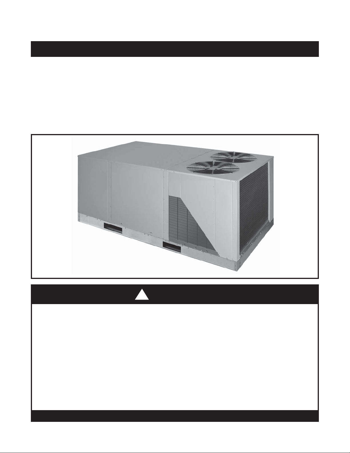
Q6SP-090 Shown
!
WARNING:
• Under no circumstances should the appliance owner attempt to install and/or service this
equipment. Some local codes require licensed installation / service personnel for this
type of equipment. Improper service, adjustment, or maintenance may cause explosion,
fi re, electrical shock or other hazardous conditions which may result in personal injury or
property damage.
• Read these instructions thoroughly before using the equipment. Follow all precautions and
warnings contained within these instructions and on the unit.
• Improper installation, adjustment, alteration, service, or maintenance can cause personal
injury or property damage. Refer to this manual. For assistance or additional information,
consult a qualifi ed installer or service agency.
• Do not store or use gasoline or other fl ammable vapors and liquids in the vicinity of this or
any other appliance.
DO NOT DESTROY. PLEASE READ CAREFULLY AND KEEP IN A SAFE PLACE FOR FUTURE REFERENCE.
Page 2
ABOUT THE HEAT PUMP
Your heat pump is a unique, all weather comfort-control
appliance that will heat and cool your building year round
and provide energy saving comfort. It’s an unknown fact
that heat is always in the air, even when the outside
temperature is below freezing. The heat pump uses this
basic law of physics to provide energy saving heat during
the winter months. For example, If the outdoor temperature
is 47° F (8° C), your heat pump can deliver approximately
3.5 units of heat energy per each unit of electrical energy
used, as compared to a maximum of only 1 unit of heat
energy produced with conventional heating systems.
In colder temperatures, the heat pump performs like
an air conditioner run in reverse. Available heat energy
outside the building is absorbed by the refrigerant and
exhausted inside. This effi cient process means you only
pay for “moving” the heat from the outdoors to the indoor
area. You do not pay to generate the heat, as is the case
with more traditional furnace designs.
During summer, the heat pump reverses the fl ow of the
heat-absorbing refrigerant to become an energy-effi cient,
central air conditioner. Excess heat energy inside the home
is absorbed by the refrigerant and exhausted outside the
building.
IMPORTANT SAFETY INFORMATION
WARNING:
To avoid possible equipment damage, fi re, or
personal injury, the following instructions must
be observed regarding unit maintenance and
operational procedures.
The Q6SP Series package heat pump rooftop unit has
been designed and built to provide many years of safe
and dependable comfort, providing it is properly installed
and maintained. With regular maintenance, this unit will
operate satisfactorily year after year. Abuse, improper
use, and/or poor maintenance can shorten the life of the
appliance and create unsafe hazards. A regular service
and maintenance schedule should be established to
ensure effi cient and safe operation of the unit. See System
Maintenance on page 3.
• To achieve optimum performance and minimize
equipment failure, it is recommended that periodic
maintenance be performed on this unit. The ability
to properly perform maintenance on this equipment
requires certain mechanical skills and tools.
• The area around the unit and the vicinity of any other
appliances must be kept clear and free of combustible
materials, gasoline, and other fl ammable vapors and
liquids. Do not store or use fl ammable items such as
paint, varnish, or strippers in the vicinity of the unit.
• Do not use the area around the unit as a storage area.
This area must be kept clean and clear of loose or
exposed insulation materials. Examine the unit’s area
when it is installed or when insulation is added, since
some insulation materials may be combustible.
• Do not use this appliance if any part has been under
water. Immediately call a qualifi ed service technician
to inspect the unit and to replace any part of the
electrical control system that has been under water.
• Familiarize yourself with the controls that shut off the
electrical power to the unit. If the unit is to be shut down
for an extended period of time, turn off the electrical
power. For your safety always turn off the electrical
power before performing service or maintenance on
the furnace.
• Do not block or obstruct air openings on the unit or air
openings supplying the area where it is installed.
• The duct connections must be physically sound
and sealed to the unit’s casing. The return air and
circulating air ductwork must not be connected to any
other heat producing device such as a fi replace insert,
stove, etc. Improperly installed ductwork may result
in fi re, explosion, personal injury, carbon monoxide
poisoning, or property damage.
OPERATING INSTRUCTIONS
Thermostat styles vary. Some models may not include
the AUTO mode and others will have the AUTO in place
of the HEAT and COOL. Others may include all three.
Some thermostats may have anti-short cycle protection
built in causing a delay in one or both stages. A protective
timer circuit may hold the compressor(s) off for up to 5
minutes following a previous operation or an interruption
of the main power. Please refer to the thermostat’s User
Manual for detailed programming instructions.
The thermostat should be mounted about 5 feet above the
fl oor on an inside wall and not on an outside wall or other
location where its operation may be adversely affected by
radiant heat from fi replaces, sunlight, or lighting fi xtures,
and convective heat from warm air registers or electrical
appliances.
Cooling Operation
1. Set the thermostat system mode to COOL and the
thermostat fan mode to AUTO (See Figure 1, page 3).
2. Set the thermostat temperature selector to the desired
temperature level. The outdoor fans, compressors,
and indoor blower will all cycle on and off to maintain
the indoor temperature at the desired cooling level.
NOTE: This unit is equipped with a fi ve minute antishort cycle timer (ASCT) built in to the defrost control
board for Stage 1 Heat or Cool. If the thermostat temperature level is re-adjusted, or if the system mode is
changed, the compressor may not start immediately.
Stage 2 Heat/Cool has no ASCT protection and can
operate immediately upon a call from the thermostat.
2
Page 3

Heating Operation (2 or 3 Stage)
2 individual refrigerant systems + Electric Heat (if installed)
1. Set the thermostat system mode to Heat and the
thermostat fan mode to AUTO (See Figure 1).
2. Raise the thermostat temperature switch above
room temperature and observe that the outdoor fans,
compressor(s), and indoor blower all cycle on and off.
NOTES:
• This unit is equipped with a 5 minute anti-short cycle
timer (ASCT) built into the defrost control board for
Stage 1 Heat or Cool. If the thermostat temperature
level is re-adjusted, or if the system mode is changed,
the compressor may not start immediately. Stage 2
Heat/Cool has no ASCT protection and can operate
immediately upon a call from the thermostat.
• If electric heat has been installed, the Stage 2
compressor will cycle off while Stage 3 heater
elements cycle on.
Emergency Heat
Most heat pump thermostats will include a system mode
called EM.HT. or AUX.HT, etc. This is a back-up heating
mode that should only be used only if a problem is
suspected. With the system switch set to Emer. Ht., etc.,
the compressor(s) and outdoor fans will be locked off
and supplemental heat (electric resistance heating) will
be used as a source of heat. Sustained use of electric
resistance heat in place of the heat pump will result in an
increase in electric utility costs.
Defrost Mode
During cold weather heating operation, the outdoor unit
will develop a coating of ice and frost on the outdoor heat
transfer coil. This is normal and the unit will defrost itself
automatically. During the defrost cycle, the outdoor fans
will stop while the compressor(s) continue to operate and
heat the outdoor coil, causing the ice and frost to melt.
During defrost, some steam may rise from the outdoor
unit as the warm coil causes the melted frost to evaporate.
Operating the Indoor Blower Continuously
Continuous indoor blower operation is typically used to
circulate the indoor air to equalize a temperature imbalance
due to solar loads, occupancy loads, or mechanical
equipment operation.
Fan
Mode
Figure 1. Digital Thermostat
System
Mode
Temperature
Selector
UNIT MAINTENANCE
WARNING:
Verify all electrical power to the unit is shut off
before performing the following recommended
maintenance.
Proper maintenance is most important to achieve the best
performance from the appliance and should be performed
by a qualifi ed service technician at least once a year.
Follow the maintenance schedule and the instructions
below for years of safe, trouble free operation.
• Do not place combustible materials on or against the
cabinet. Do not store gasoline or any other fl ammable
vapors and liquids in the vicinity of the unit.
• Annually inspect the physical support of the unit to
ensure that it is physically sound without sagging,
cracks, gaps, etc., around the base so as to provide a
seal between the support and the base.
• Annually inspect the return-air connection to ensure
that it is physically sound and is still sealed to the
casing of the unit. Also inspect the unit, ductwork, and
vent system for signs of physical deterioration.
• Always replace the doors on the unit after servicing.
Do not operate the unit without all doors and covers
in place. Avoid operating the unit when windows and
doors are open.
Regular Cleaning
Set the thermostat fan mode to ON (or CONT on
some thermostat models). The indoor blower will start
immediately, and run continually until the fan switch is
reset to AUTO. NOTE: The continuous indoor blower
operation can be obtained with the thermostat system
switch set in any position, including OFF.
System Shutdown
Set the thermostat system mode to OFF and the thermostat
fan mode to AUTO. See Figure 1. NOTE: The system will
not operate, regardless of the thermostat temperature
selector’s setting.
WARNING:
DO NOT touch any of the internal electrical
components while cleaning the unit.
• Remove any debris from the outdoor coil Being careful
not to damage the aluminum fi ns.
• Inspect the condensate drain at the beginning of each
cooling season. Remove any debris.
• Clean the blower compartment regularly during the
heating and cooling seasons to remove any dust that
may have accumulated in the compartment or on
3
Page 4

the blower and motor. Buildup of dust on the blower
and motor can create excessive loads on the motor
resulting in higher than normal operating temperatures
and possible shortened service life.
Motor Lubrication
The motors for the circulating air blower and outdoor fan
are pre-lubricated and sealed by the manufacturer. No
further oiling is required for the life of this product.
Air Filters
WARNING:
Never operate the unit without a fi lter in the
return air system. Dust and lint in the return
air can build up on the internal components,
resulting in loss of efficiency, equipment
damage, and possible fi re risk.
• Q6SP Series units are factory equipped with pleated
2 inch disposable fi lters. The fi lters should be checked
periodically and replaced (or cleaned) when necessary
with fi lters of the same dimensional size. Replace
using disposable fi lters with a minimum airfl ow rating
of 500 FPM or permanent fi lters only.
• The fi lter rack is fi eld adjustable to accommodate 1”
permanent fi lters. DO NOT use 1” disposable fi lters in
these units.
• Always replace the fi lter access panels after changing
or cleaning the fi lters. DO NOT operate unit without
the fi lter access panels in place.
• It is very important to replace or clean the fi lter(s)
installed in the return air duct of this system. A clogged
fi lter could cause airfl ow related problems and reduce
the overall effi ciency of your unit. Always replace
disposable fi lter(s) installed in your system only
with the same size dimensional fi lters that are being
replaced.
• Filters must be ULC approved or equivalent for use in
Canada.
TROUBLESHOOTING
Before you call a Technician, check the following:
• Check the thermostat setting. Make sure the system
mode and temperature settings are correct.
• Check the electrical panel for tripped circuit breakers.
• Check the fi lters for dust accumulation.
• If the items above don’t resolve your problems, then
call your nearest service technician.
WARRANTY INFORMATION
A warranty certifi cate with full details is included with the
equipment. Carefully review these responsibilities with
your dealer or service company. The manufacturer will not
be responsible for any costs found necessary to correct
problems due to improper setup, improper installation,
adjustments, improper operating procedure on the part
of the user, etc.
Some specifi c examples of service calls which are not
included in the limited warranty are:
• Correcting wiring problems in the electrical circuit
supplying the equipment.
• Resetting circuit breakers or other switches.
• Adjusting or calibrating of thermostat.
Specifi cations & illustrations subject to change without notice or incurring obligations.
O' Fallon MO | Printed in U.S.A. (12/10)
¢708760.¤
708760A (Replaces 7087600)
 Loading...