

Page 1
Form P-COND (Version 11-14)
Obsoletes P-COND (Version A.1)
IMPORTANT
1. Always include complete model and serial
number so that any specication change can
be considered for parts replacement. It can
save time and expense.
2. In keeping with our policy of continuous
product improvement, we reserve the
right to alter any information shown here.
Specications are subject to change without
notice.
3. We reserve the right to substitute functional
replacements
4. Order by P/N; not Option Designation.
Index
A
Access Panel 7
C
Cabinet Parts 7
Capacitor 3
Compressor Mounting Kit 5
Compressor Plug 5
Compressors 4
Compressor Section 4
Condenser Coil Guard 6
Condenser Coils 6
Condenser Fan and Motor 5
Contactors 3
Control Compartments 3
Corner Post 7
Crankcase Heater 5
E
Electrical Components 3
F
Fan Blade 5
Fan Guard 5
Fan Motor 5
Liquid Line Filter Driers 6
G
Grommet 7
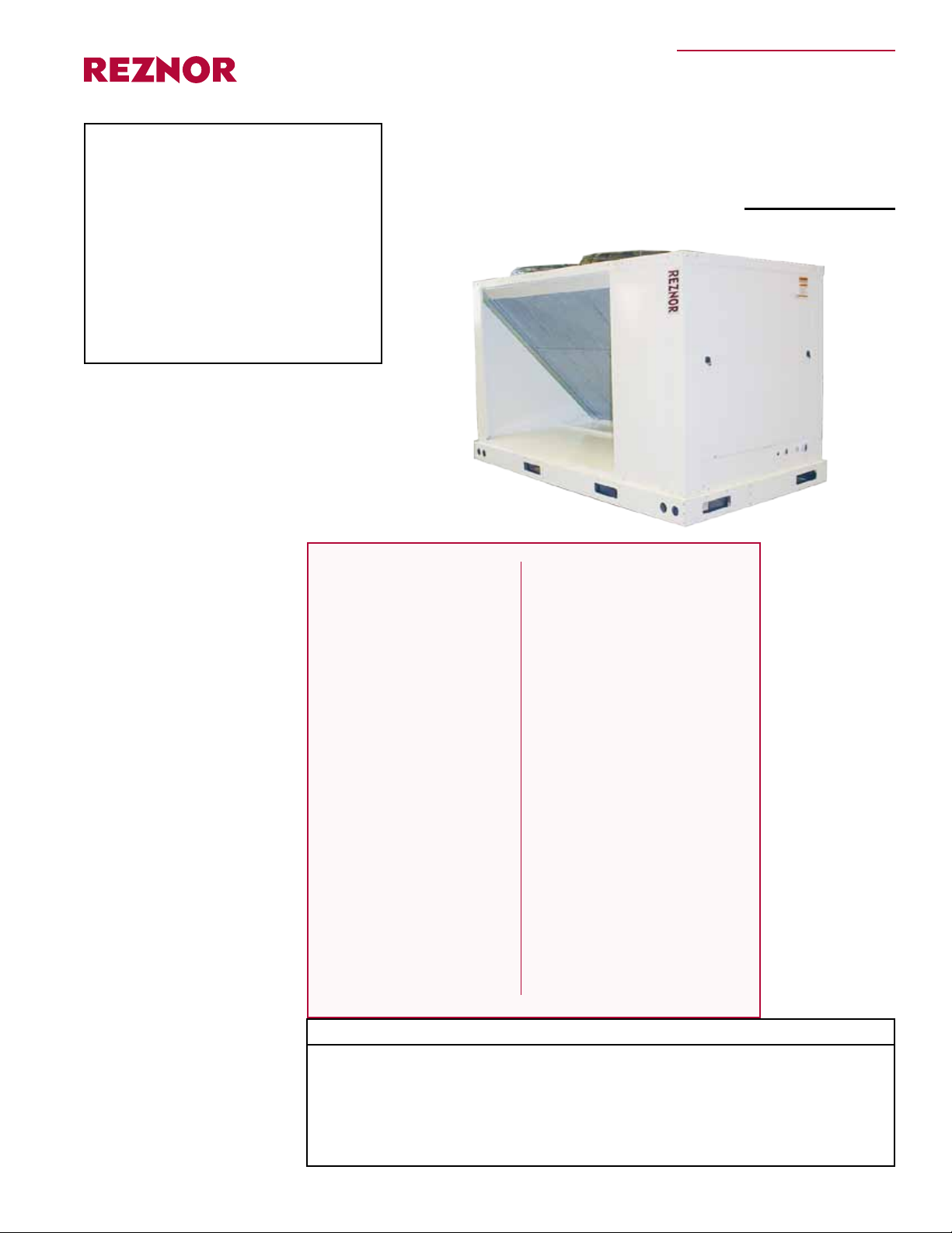
Replacement Parts
Applies to: Condensing Unit
Model MASA
H
Hot Gas Bypass Valve 5
L
Latch 7
P
Paint 7
High Pressure Switch 5
Low Pressure Switch 5
Pull Tab 7
R
Rating Plate 2
Rawal Valve Options 8
Refrigerant Receiver 5
Relay 3
S
Serial No 2
Service Panel 7
Side Panel 7
T
Timer Board 3
Condenser Section Top 7
Control Compartment Top 7
Transformer 3
References:
Model MASA Installation Manual, Form I-COND
Additional references if installed with a Reznor Air Handler:
Installation Manual, Form I-PDH/SDH/PEH/SHH/PXH
Installation Manual, Form I-RDH/REH/RXH
Operation Manual, Form O-PREEVA & SHH
Replacement Parts, Form P-PREEVA & SHH
Installation Manual, Form, I-CAUA-CC
P-COND (11-14), P/N 268631R2, Page 1
Page 2
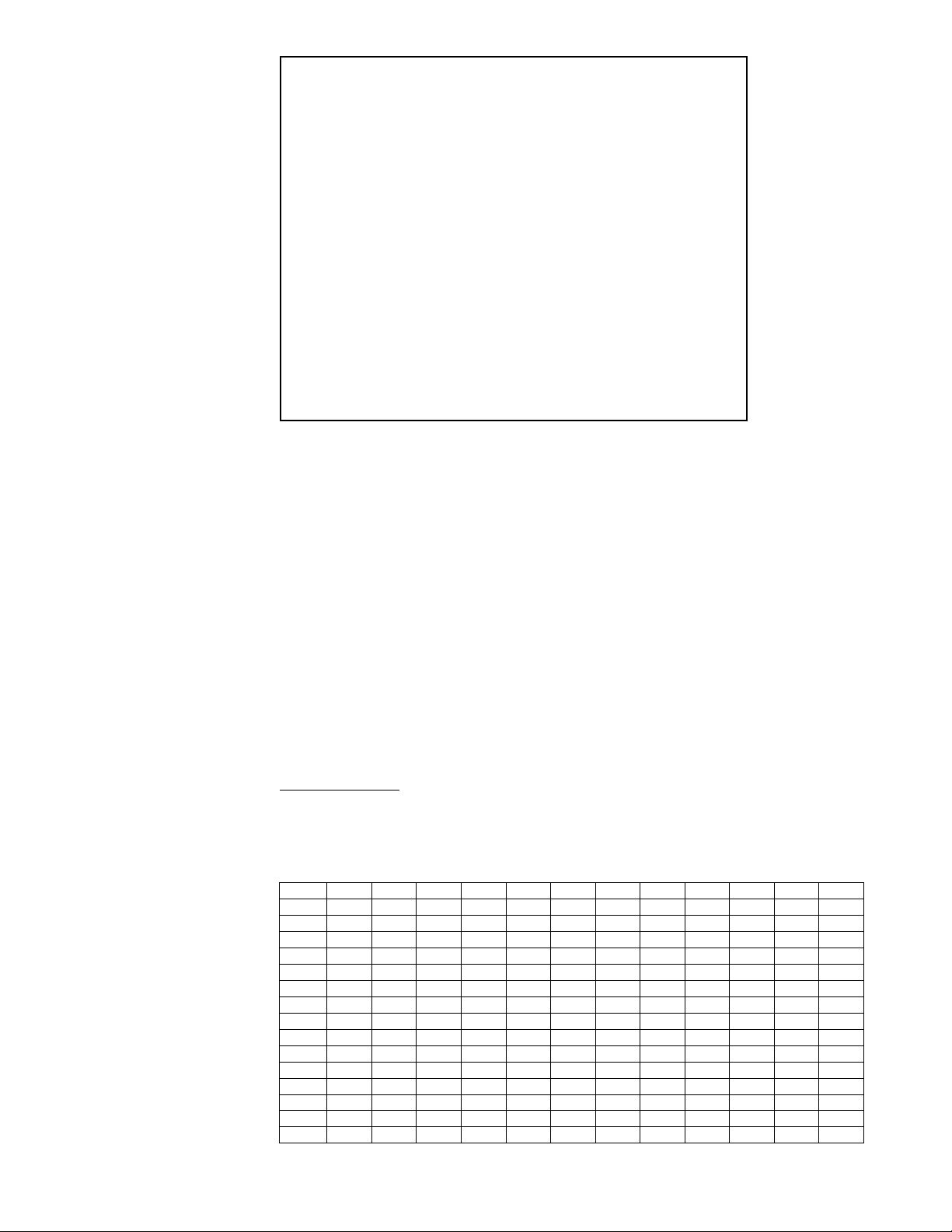
Rating Plate and
Serial No.
REZNOR
MERCER, PA. USA 16137
MADE IN USA
FOR INDUSTRIAL/COMMERCIAL USE ONLY
FOR OUTDOOR USE
MODEL [ A ] [ B ] [ C ] BTU
SERIAL NO. [ ]
[ D ] VOLTS +/- 10% [ D ] PH [ D ] HZ
MINIMUM CIRCUIT AMPACITY (MCA) [ F ] AMPS
MAXIMUM FUSE SIZE/*CIRCUIT BREAKER (MOP) [ G ] AMPS
SHORT-CIRCUIT CURRENT: 5,000 RMS SYMMETRICAL, [D] V MAXIMUM
QTY FLA (EACH) HP (EACH)
CONDENSER FAN MOTOR (S) [ T ] [ U ] [ Z ]
QTY RLA (EA) LRA (EA)
COMPRESSOR A (1st STAGE) [ H ] [ I ] [ J ]
COMPRESSOR B (2nd STAGE) [ K ] [ L ] [ M ]
MINIMUM R-410A DESIGN PRESSURE IS 45 PSI
MAXIMUM R-410A DESIGN PRESSURE IS 600 PSI
WIRE DIAGRAM [ AA ]
*HACR TYPE REQUIRED PER NEC
Rating Plate Key
Serial No.
Month and Year Date
Code Table for Decoding
Serial No.
A = Model MASA 060, 090, 120, 150, 180,
240
B = Manufacturing Date
C = BTU
D = Volts (208/230; 480; 575),
3 Phase, 60 Hz
F = Minimum Circuit Ampacity
G = Maximum Fuse Amps
K = 1 Circuit B Compressor
L = Circuit B Compressor Rated Load Amps
M = Circuit B Compressor Locked Rotor
Amps
T = Condenser Fan Quantity (1 or 2)
U = Condenser Fan Load (Amps)
Z = Condenser Fan Motor HP (.75)
AA = Wiring Diagram No.
H = 1 Circuit A Compressor
I = Circuit A Compressor Rated Load (Amps)
J = Circuit A Compressor Locked Rotor
(Amps)
The serial number consists of an alpha date Code, a numeric date Code, and a consecutive
number.
Serial No. Example: BGJ400705394
BGJ = Date Code from table below
4007 = 40th week of the year 2007
05394 = Consecutive number
Year Jan Feb Mar Apr May June July Aug Sept Oct Nov Dec
2006 B FA BFB BFC BFD BFE BFF BFG BFH BFI BFJ BFK BFL
2007 BGA BGB BGC BGD BGE BGF BGG BGH BGI BGJ BGK BGL
2008 BHA BHB BHC BHD BHE BHF BHG BHH BHI BHJ BHK BHL
2009 BIA BIB BIC BID BIE BIF BIG BIH BII BIJ BIK BIL
2010 BJA BJB BJC BJD BJE BJF BJG BJH BJI BJJ BJK BJL
2011 BKA BKB BKC BKD BKE BKF BKG BKH BKI BKJ BKK BKL
2012 BLA BLB BLC BLD BLE BLF BLG BLH BLI BLJ BLK BLL
2013 BMA BMB BMC BMD BME BMF BMG BMH BMI BMJ BMK BML
2014 BNA BNB BNC BND BNE BNF BNG BNH BNI BNJ BNK BNL
2015 BOA BOB BOC BOD BOE BOF BOG BOH BOI BOJ BOK BOL
2016 B PA BPB BPC BPD BPE BPF BPG BPH BPI BPJ BPK BPL
2017 BQA BQB BQC BQD BQE BQF BQG BQH BQI BQJ BQK BQL
2018 BRA BRB BRC BRD BRE BRF BRG BRH BRI BRJ BRK BRL
2019 BSA BSB BSC BSD BSE BSF BSG BSH BSI BSJ BSK BSL
2020 BTA BTB BTC BTD BTE BTF BTG BTH BTI BTJ BTK BTL
P-COND (11-14), P/N 268631R2, Page 2
Page 3
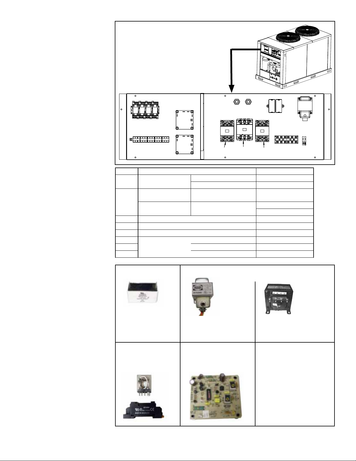
Electrical
Components in the
Control Compartment
Control
Compartments
1
3
3
3
3
4
444
24V Terminal
Block
Code Description P/N
1 Capacitor
Transformer with
circuit breaker, 75 VA
2
Transformer with fuse Use with AK8, 575/3/60
3 Relay LY2 211411
4 Relay Mounting Socket 211415
5 Compressor Protect Board (anti-short cycle timer) 216385
6
7
3 Pole Contactor
8
Code 1 - Capacitor
5
5
7
460/3/60 and 575/3/60 207447, 7.5 MFD
208-230/3/60 207448, 10 MFD
Use with AK20, 208-
230/3/60 and AK7, 460/3/60
25 Amp 216386
40 Amp 216387
50 Amp 216388
8
Code 2 - Transformers
1
Terminal
6
208989
Transformer - 39095
Fuse - 201773
Block
2
Ground
Lug
P/N 207447,
7.5MFD/440V
P/N 207448,
10 MFD/370V
Code 3 & 4 - Relay,
P/N 211411, with
Socket, P/N 211415
Transformer with Circuit
Beaker, 75VA, 120/208240/480-24v, P/N 208989
Code 5 - Anti-Short Cycle
Timer Board (Option
CUB1), P/N 216385
Transformer, 200VA,
575-24v, P/N 39095, with
Fuse, P/N 201773
Codes 6, 7, & 8 Contactors, 3 Pole
Code 6 - P/N 216386,
25AMP, HCC-3XQ01CY
Code 7 - P/N 216387,
40AMP, HCC-3XQ04CG
Code 8 - P/N 216388,
50AMP, HCC-3XQ05CJ
P-COND (11-14), P/N 268631R2, Page 3
Page 4
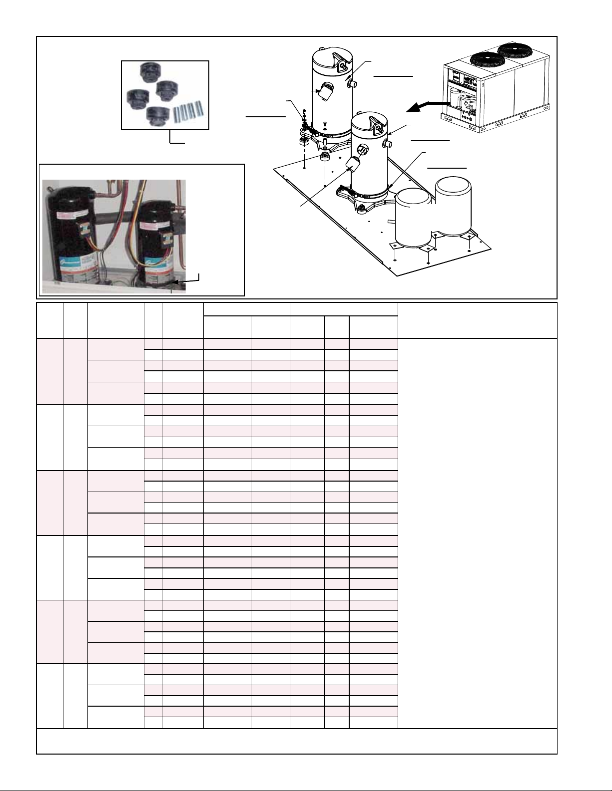
Compressor Section
12
12
11
Circuit B
10
Circuit A
10
Circuit B
11
Circuit A
Receivers,
Code 13
Compressor Mounting
Grommet Kit, Code 14
A
B
Code 10 - R410A Scroll Compressors
Code 11 Crankcase
Heater
(belly band
type)
10 - Compressor 11 - Crankcase Heater
Model*
ZP20K5E
ZP39K5E
ZP29K5E
ZP39K5E
Reznor
216671
216672
261238 216437
261239 216397
234055
261239
P/N
Reznor
P/N
a
216434
b
216436
c
216437 40
d
216397
Watts
ZP83KCE 216691 216401
e
216394
f
216396
g
216397
235008
235012
235016
216401 70 7.4 (188)
Diameter
in. (mm)
40 5.5 (140)
40 5.5 (140)
40 5.5 (140)
6.6 (168)
40
40 5.5 (140)
5.5 (140)
5.5 (140)
40 6.6 (168)
70 7.4 (188)
40 6.6 (168)
40 6.6 (168)
40 6.6 (168)
Replacement Notes
a
Replaces Model ZP20K3E (same
P/N) which has a diameter of 6.6”
(168mm). Replacement requires a
200/230V crankcase heater with a
5.5” (140mm) diameter, P/N 216434.
b
Replaces Model ZP20K3E (same
P/N) which has a diameter of 6.6”
(168mm). Replacement requires
480V crankcase heater with a 5.5”
(140mm) diameter, P/N 216436.
c
Replaces Model ZP29K3E, P/N
216676 (could also be labeled
ZP32K3E, ZP32K5E, or ZP29K5E),
which has a diameter of 6.6”
(168mm). Replacement requires a
575V crankcase heater with a 5.5”
(140mm) diameter, P/N 216437.
d
Replaces Model ZP41K3E, P/N
216680, which has a diameter of
6.6” (168mm) and requires the same
crankcase heater as the replacement
compressor.
e
Replaces Model ZP54K3E, P/N
216682, which has a diameter of
7.4” (188mm). Replacement requires
200/230V crankcase heater with a
6.6” (168mm) diameter, P/N 216394.
f
Replaces Model ZP54K3E, P/N
216683, which has a diameter of
7.4” (188mm). Replacement requires
480V crankcase heater with a 6.6”
(168mm) diameter, P/N 216396.
g
Replaces Model ZP54K3E, P/N
216684, which has a diameter of
7.4” (188mm). Replacement requires
575V crankcase heater with a 6.6”
(168mm) diameter, P/N 216397.
MASA
Model
Option and
Nominal
Tonnage
Voltage
Voltage
200-230/3/60
060 5
480/3/60
575/3/60
200-230/3/60
090 8
480/3/60
575/3/60
200-230/3/60
120 10
480/3/60
575/3/60
200-230/3/60
150 13
480/3/60
575/3/60
200-230/3/60
180 15
480/3/60
575/3/60
200-230/3/60
240 20
480/3/60
575/3/60
AK20
AK7
AK8
AK20
AK7
AK8
AK20
AK7
AK8
AK20
AK7
AK8
AK20
AK7
AK8
AK20
AK7
AK8
Nominal
Tonnage
by Circuit
Circuit
A 2 ZP20K5E
B 3 ZP39K5E 216678 216394 40 6.6 (168)
A 2 ZP20K5E
B 3 ZP39K5E 216679 216396 40 6.6 (168)
A 2
B 3
A 2 ZP29K5E 216674 216434
B 5 ZP57K3E 216686 216398 70 7.4 (188)
A 2 ZP29K5E 216675 216436 40
B 5 ZP57K3E 216687 216400 70 7.4 (188)
A 3
B 5 ZP57K3E 216688 216401 70 7.4 (188)
A 3 ZP39K5E 216678 216394 40 6.6 (168)
B 7 ZP83KCE 216689 216398 70 7.4 (188)
A 3 ZP39K5E 216679 216396 40 6.6 (168)
B 7 ZP83KCE 216690 216400 70 7.4 (188)
A 3
B 7
A 4 ZP54K5E
B 8 ZP103KCE 216692 216402 90 9.17 (233)
A 4 ZP54K5E
B 8 ZP103KCE 216693 216404 90 9.17 (233)
A 4 ZP54K5E
B 8 ZP103KCE 216694 216405 90 9.17 (233)
A 5 ZP57K3E 216686 216398 70 7.4 (188)
B 10 ZP120KCE 216695 216402 90 9.17 (233)
A 5 ZP57K3E 216687 216400 70 7.4 (188)
B 10 ZP120KCE 216696 216404 90 9.17 (233)
A 5 ZP57K3E 216688 216401 70 7.4 (188)
B 10 ZP120KCE 216697 216405 90 9.17 (233)
A 7 ZP83KCE 216689 216398 70 7.4 (188)
B 13 ZP154KCE 220260 216402 90 9.17 (233)
A 7 ZP83KCE 216690 216400 70 7.4 (188)
B 13 ZP154KCE 220261 216404 90 9.17 (233)
A 7 ZP83KCE 216691
B 13 ZP154KCE 220262 216405 90 9.17 (233)
*Model No. of the replacement R410A scroll compressor must be identical to the one removed or the replacement listed including the
"E" (ZP39KxExxx) which indicates POE compressor oil.
P-COND (11-14), P/N 268631R2, Page 4
Page 5

1” to 1-1/2” maximum
2-1/2”
1/2”
Fan and Motor
Assembly
Rotation and
Assembled
Dimensions
20
22
21
25
24
23
26
74/75,
page 7
Code 11 Crankcase
Heater
Code
Description MASA 60 MASA 90 MASA 120 MASA 150 & 180 MASA 240
12 Compressor Plug with 5ft leads (2) 205630, 10 ga wires (2) 223028, 6 ga wires
13 Liquid Refrigerant Receiver (see page 4) (2) 220480
14 Compressor Mounting Kit (see page 4) (2) 205825
15 High Pressure Switch (discharge line) (2) 216379
16 Low Pressure Switch (suction line) (2) 216380
Hot Gas
17
Bypass Valve
Voltage
P/N 216394 216434 216398 216402 216396 216436 216400 216404 216437 216397 216401 216405
Watts 40 70 90 40 70 90 40 70 90
Diameter 6.6” 5.5” 7.4” 9.17” 6.6” 5.5” 7.4” 9.17” 5.5” 6.6” 7.4” 9.17”
The element straps around the bottom of the compressor so the diameter must match.
See usage by Model Size and compressor on page 4.
Circuit A only (CUG2) (1) 220518, 3/8”
Circuits A & B (CUG3) (2) 220518, 3/8” (1) 220518, 3/8” & (1) 220517, 1/2”
Option AK20 Option AK7 Option AK8
208/230/3/60 480/3/60 575/3/60
Code 12 - Compressor
Plug
See P/N’s and application
in table.
Condenser Fan
and Motor
Code 15 - High Pressure
Switch (discharge line),
#IMPS-072-600R, P/N 216379
Code 16 - Low Pressure
Switch (suction line),
#ILPS- 072-025E050E,
P/N 216380
Code 17 - Hot
Gas Bypass
Valve, Sporlan
P/N 220518, 3/8”
P/N 220517, 1/2”
Condenser Unit Model Size
Code Description Voltage
20 Fan Blade, 26”, 21° 216381 (2) 216381
21 Fan Motor, 3/4HP 205628 205629 (2) 205628 (2) 205629
22 Motor Support 157107 (2) 157107
23 Hex Head Bolt 16248 (2) 16248
24 Lockwasher 1333 (2) 1333
25 Nut 1035 (2) 1035
26 Fan Guard 217135 (2) 217135
MASA 60 and 90 MASA 120, 150, 180 and 240
AK20 AK7 AK8 AK20 AK7 AK8
208/230/3/60 480/3/60 575/3/60 208/230/3/60 480/3/60 575/3/60
P-COND (11-14), P/N 268631R2, Page 5
Page 6

Coil Guard,
CODE 54
Screws with washers
across the top,
CODES 51 and 53
Screws across the
bottom, CODES 52 and 53
Code 40 - Liquid Line
Filter Driers
MASA Refrigerant Circuit R410A Liquid Line Filter Driers *
Size Tons Circuit Tonnage Model Reznor P/N Connection Size
60 5
90 8
120 10
150 13
180 15
240 20
* Shipped loose in the condenser section of the original MASA unit shipment.
A 2 C-084-S 177378 1/2
B 3 C-164-S 177379 1/2
A 3 C-084-S 177378 1/2
B 5 C-164-S 216408 1/2
A 3 C-164-S 177379 1/2
B 7 C-304-S 216408 1/2
A 4 C-164-S 177379 1/2
B 8 C-304-S 216408 1/2
A 5 C-164-S 216408 1/2
B 10 C-414-S 216409 1/2
A 7 C-304-S 216408 1/2
B 13 C-415-S 216410 5/8
Condenser Coils
NOTE: Coils are aluminum
Micro-Channel and require
aluminum to copper brazing.
Code
30
31
Condenser Coil Guard,
Option AZ12
P/N’s & Sizes of coils used prior to 10/2008.
IMPORTANT: The P/N’s listed in the table above are
not a direct replacement for these previously used
coils. Before ordering, check with your distributor or
the factory on availability or alternate replacement.
Code
30
31
P/N’s & Sizes of
coils used beginning
10/2008 (Serial No.
Code BHJ) - See
page 2 to decode
the Serial No.
Condenser Coil
(Lower Section)
Condenser Coil
(Upper Section )
Description
Condenser Coil
(Lower Section)
Condenser Coil
(Upper Section )
Description
MASA 60
and 90
255510
34x35
255509
21x35
MASA 60
and 90
217166
34x35
217167
21x35
MASA 120
and 150
255511
34x60
255508
20x60
MASA 120
and 150
217168
34x60
217169
20x60
MASA
180
217170
38x84
217171
19x84
MASA 180
and 240
255513
30x84
255512
20x84
MASA
240
220948
30x84
220949
20x84
Code Description MASA 60 and 90 MASA 120 and 150 MASA 180 and 240
50 Condenser Coil Guard, Option AZ12 220607 220608 220609
Components:
51 Tek #10-16x3/4 Hex Zinc Pl (3) 51356 (4) 51356
52 Screw 3/4 Type Ab Hex Screw (3) 99542 (5) 99542
53 Flat Washer 3/16 #10 (6) 113807 (9) 113807
54 Condenser Coil Guard 220285 220284 220283
P-COND (11-14), P/N 268631R2, Page 6
Page 7

Cabinet Parts
60
60A
66
62
65
67
64
61
69
72
70
71
74
73
Cabinet Parts for
MASA Sizes 120,
150, 180, 240
75
63
68
NOTE: If cabinet parts not
shown are required, contact
your distributor or the factory
service department.
Cabinet Parts for
MASA Sizes 60, 90
60A
60
69
65
63
66
61
64
67
73
74
72
70
68
62
Code Description 60, 90 120, 150 180, 240
60 Access Panel Assembly 217182
Access Panel Latch, Southco #E5-2-005-071 (2) 223351
60A
Pull Tab (2) 204470
61 Left Compressor Compartment Service Panel 217161
62 Right Compressor Compartment Service Panel 217160
63 Clip-on Nut for Service Panels (2) 221262
64 Grommet 1-3/8" 19816
65 Grommet 7/8" 107607
66 Grommet 1/2" (2) 111067
67 Grommet SR 3/4" (2) 220545
68 Compressor End Right Corner Post 217172
69 Compressor End Left Corner Post 216718
217175 217120 216723
217121 216731
217115 217114 217113
P-COND (11-14), P/N 268631R2, Page 7
217174 217173
70
Solid Side Panel
71
72 Solid End Panel (includes corners) 217147
73 Control Compartment Top 216422
74
Condenser Section Top
75
76
Reznor Label 196689
77
Cabinet Touchup Paint 201805, 11 oz spray can
Page 8

Rawal Valve Options
Rawal Valve
CUG4
Internal Capacity Control
on 2/3 Circuit Only
B Circuit
Model Size
CUG4
Rawal Valve P/N 261613 259506 259507 263944
60 90 120 150 180 240
B Circuit B Circuit B Circuit B Circuit
P-COND (11-14), P/N 268631R2, Page 8
Page 9

Rawal Valve Options (Cont’d)
B Circuit
Rawal Valve
A Circuit
CUG5
Internal Capacity Control
on Both Circuits
Model Size
CUG5
A Circuit B Circuit A Circuit B Circuit A Circuit B Circuit A Circuit B Circuit A Circuit B Circuit
Rawal Valve P/N 259506 261613 259507 261613 259506 259507 259506 263944 259506 263944
90 120 150 180 240
P-COND (11-14), P/N 268631R2, Page 9
Page 10

NOTES:
P-COND (11-14), P/N 268631R2, Page 10
Page 11

NOTES:
P-COND (11-14), P/N 268631R2, Page 11
Page 12

P-COND (11-14), P/N 268631R2, Page 12
www.ReznorHVAC.com; (800) 695-1901
©2014 Reznor LLC, All rights reserved.
Trademark Notes: Reznor® is registered in at least the United Sates.
All other trademarks are the property of their respective owners.
Form P-COND (Version 11-14)
 Loading...