

Page 1
Form O-MAPSIII Cabinet D (Version D)
CQS
Obsoletes Form O-MAPSIII Cabinet D (Version C)
®
Operation / Maintenance / Service
Applies to: Models RCB, RDB, RDCB,
®
™
RDDB, RECB, and REDB
Cabinet "D" Sizes
P
R
O
Y
C
R-410A
Refrigerant
C
N
E
G
O
A
C
C
U
S
T
O
M
CQS
E
Q
R
U
A
P
R
O
D
E
S
R
E
G
S
V
E
N
N
T
P
U
-
T
R
A
T
S
M
Y
E
T
T
L
S
I
T
U
C
N
Y
Y
S
A
R
R
A
T
W
DANGER
This unit contains R-410A high pressure refrigerant. Hazards exist that could
result in personal injury or death. Installation, maintenance, and service should
only be performed by an HVAC technician qualied in R-410A refrigerant and
using proper tools and equipment. Due to much higher pressure of R-410A
refrigerant, DO NOT USE service equipment or tools designed for R22
refrigerant.
IMPORTANT: Do not release refrigerant to the atmosphere! If required service
procedures include the adding or removing of refrigerant, the service technician
must comply with all federal, state and local laws. The procedures discussed
in this manual should only be performed by a qualied HVAC technician.
Form O-MAPSIII Cabinet D, P/N 222918R9, Page 1
Page 2
Table of Contents
1.0 General ................................................................2
2.0 Maintenance Requirements .......................... 3-5
2.1 Maintenance Schedule ........................................3
2.2 Control Locations .................................................4
2.3 MAPSIII D Cabinet Sizes .....................................5
3.0 Maintenance/Service Procedures .............. 5-21
3.1 Filters ..................................................................5
3.2 Drive Components ...............................................6
3.3 Condenser Fans ..................................................6
3.4 Coil Maintenance .................................................7
3.5 Check Refrigerant Pressure and
Temperatures (subcooling and superheat) .........9
3.6 Compressor Maintenance and Replacement ....10
3.7 Thermostatic Expansion Valves .........................18
3.8 Dampers and Damper Controls .........................19
3.9 Other Controls ...................................................19
1.0 General
This booklet includes operation, maintenance, and service information on the MAPS®III
Cabinet D Size systems. Before beginning any procedure, carefully review the information, paying particular attention to the warnings. Handling of refrigerant should only
be performed by a certied HVAC technician with knowledge of the requirements of
R-410A refrigerant and in compliance with all codes and requirements of authorities
having jurisdiction.
The instructions in this manual apply to the following MAPS®III models.
4.0 Gas Heat Section Maintenance - Models
RDCB and RDDB ........................................ 21-33
4.1 Heat Exchanger, Burner, and Venter
Maintenance .....................................................21
4.2 Gas Heat Section Controls ................................26
4.3 Gas Train ...........................................................30
4.4 Other Gas Heat Section Controls ......................32
5.0 Electric Heat Section Maintenance -
Models RECB and REDB ........................... 33-34
6.0 Troubleshooting ......................................... 35-42
6.1 Troubleshooting - All Models..............................35
6.2 Troubleshooting the Heat Section .....................36
INDEX ......................................................................43
REFERENCES .......................................................44
NOTE: To conrm that this
booklet is applicable, see
list of D Cabinet Sizes in
Paragraph 2.3, page 5.
Denitions of Hazard
Intensity Levels used
in this Manual
Model Description
RCB
RDCB
RECB
RDB
RDDB
REDB
There are warning labels on the unit and throughout this manual. For your safety,
comply with all warnings during installation, operation, and service of this system. See
denitions of Hazard Intensity Levels of warnings below.
Makeup Air Cooling Packaged System, 5200-13000 CFM
Makeup Air Cooling Packaged System, 5200-13000 CFM, with Gas
Heat Section (500-1600 MBH)
Makeup Air Cooling Packaged System, 5200-13000 CFM, with
Electric Heat Section (120 & 180 kw)
Makeup Air Cooling and Re-heat Pump Reheat Cycle Packaged
System, 5200-13000 CFM
Makeup Air Cooling and Re-heat Pump Reheat Cycle Packaged
System, 5200-13000 CFM, with a Gas Heat Section (500-1600 MBH)
Makeup Air Cooling and Re-heat Pump Reheat Cycle Packaged
System, 5200-13000 CFM, with Electric Heat Section (120 & 180 kw)
HAZARD INTENSITY LEVELS
1. DANGER: Failure to comply will result in severe personal injury or
death and/or property damage.
2. WARNING: Failure to comply could result in severe personal injury
or death and/or property damage.
3. CAUTION: Failure to comply could result in minor personal injury
and/or property damage.
Form O-MAPSIII Cabinet D, P/N 222918R9, Page 2
Page 3
2.0 Maintenance
Requirements
This unit will operate with a minimum of maintenance. To ensure long life and satisfactory performance, a system that is operating under normal conditions should be
inspected according to the Maintenance Schedule. If in an area where an unusual
amount of dust or soot or other impurities are present in the air, more frequent inspection is recommended.
Refer to the illustration in FIGURE 1, page 4, and follow the instructions in the referenced paragraphs to maintain this equipment. Maintenance requirements and procedures apply to all Models unless noted.
NOTE: If replacement parts are required, use only factory-authorized parts.
For information, go to www.ReznorHVAC.com or call 800-695-1901
WARNING
Lock power OFF before performing all maintenance procedures (except where power is
required such as checking refrigerant pressure and temperature). Lock disconnect switch
in OFF position. If the system has a heat section, when you turn off the power supply, turn
off the gas. See Hazard Levels, page 2.
2.1 Maintenance
Schedule
Monthly
□ Inspect lters; clean or replace as needed. See Paragraph 3.1.
□ Inspect the condensate drain; clean as needed. For information, see Form
I-MAPSIII&IV, Paragraph 6.2.
Semi-Annually
□ Inspect the unit blower plenum fan and belt. Check belt for tension, wear, and
alignment. Adjust or replace as needed. Clean dirt from blower and motor. See
Paragraph 3.2.
Annually
NOTE: Redo the cooling startup procedures when the cooling season begins. Refer
to Startup instructions in the installation manual, Form I-MAPSIII&IV, Paragraph 10.0.
Beginning of the cooling season or more frequently in year-round
cooling climate (applies to all Models):
□ Inspect the wiring for any damaged wire. Replace damaged wiring.
□ Inspect the condensate drain pan. Clean the coil cabinet, the drain pan, and ll the
trap.
□ Inspect/clean condenser fans. See Paragraph 3.3.
□ Inspect/clean all coils. See Paragraph 3.4.
□ Check compressor operation. See Paragraph 3.6.
□ Check refrigerant pressure and temperatures (superheat and subcool). These
checks are done when the system is operating. See Paragraph 3.5.
Models RDCB & RDDB with a gas heat section (beginning of the heating
season) - See Section 4.0.
□ Clean all dirt and grease from the combustion air openings and the venter
assembly.
□ Check the heat exchanger, burner, and venter for scale, dust, or lint accumulation.
Clean as needed.
□ Check the gas valves to ensure that gas ow is being shutoff completely.
Models RECB & REDB with an electric heat section (beginning of the
heating season) - See Section 5.0.
□ Check the wiring connections.
□ Check the heat section and electric elements for dust or lint accumulation.
Carefully clean as needed.
Form O-MAPSIII Cabinet D, P/N 222918R9, Page 3
Page 4
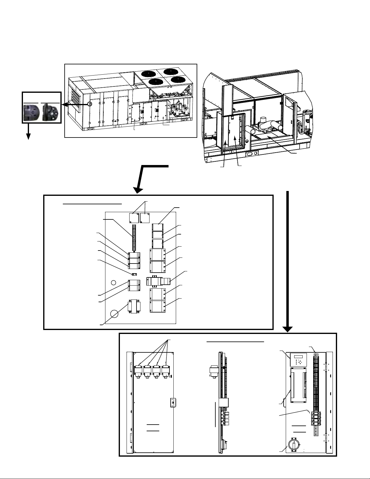
2.0 Maintenance Requirements (cont'd)
High Voltage Panel
Control
Transformer
Distribution
Block
Distribution Block
Distribution Block
Distribution Block
Distribution Block
Grounding
Lug
Terminal Blocks
Phase Loss
Monitor
Contactor (Condenser
Fan B & C)
Contactor (Condenser Fan A & D)
Contactor (Reheat Compressor E)
Contactor (Compressor D)
Contactor (Compressor C)
Contactor (Compressor B)
Contactor (Compressor A)
Motor Starter
Rear
View
Side View
Front
View
75VA
transformers
Optional Dirty
Filter Switch
Digital
Controller
Controller
Display
Wire Harness
Assembly
Optional
Relays
and Bases
Low Voltage Panel
Control Compartment
Access Door
Heater Controls
Access Door
Filter Access
Coil Access
Fan and Motor
Access
Condenser Section
A
B
C
D
2.2 Control Locations
FIGURE 1 - Access Panels and High and Low Voltage Control Locations
Door Hinge
Locked Unlocked
The lter, coil, and fan/motor cabinet
doors can be opened from the left or
right. On the side of the door to be
opened, unlock the two hinges with
an allen key. Pull out unlocked "fronts"
of hinges to 90 degrees to expose
handles needed to open the door.
Re-lock hinges when door is closed.
High Voltage Panel
(behind low voltage
panel; post is removed
for less restricted view)
Low Voltage Panel
(hinged; swings out
to access rear side and
high voltage panel behind)
Gas Heat
Section
Control Panel
(See Para 4.2.1.)
NOTE: Electric heat
Models RECB and
REDB have additional
electrical panels in
the heat section; see
Paragraph 5.0, page
33.
Form O-MAPSIII Cabinet D, P/N 222918R9, Page 4
Page 5
(2) P/N 104102,
16x16x1
(2) P/N 104102,
16x16x1
(2) P/N 104102,
16x16x1
(2) P/N 104102,
16x16x1
(2) P/N 104102,
16x16x1
(2) P/N 104102,
16x16x1
(2) P/N 101609,
16x25x1
(2) P/N 101609,
16x25x1
(2) P/N 101609,
16x25x1
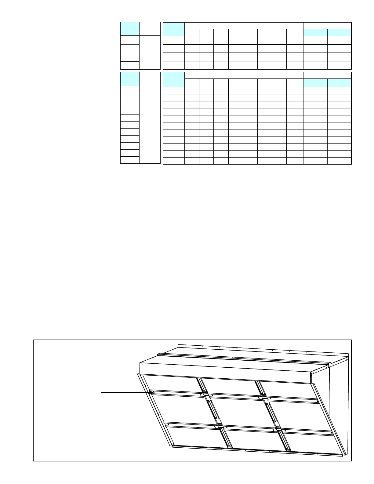
1) Loosen wing nuts and
slide clamp.
2) Remove filters.
3) Repeat for all filters.
4) Wash and dry filters.
5) Re-install filters in hood.
Be sure wing nuts are tight
and filters secure.
Filters in Hood - Cabinet D
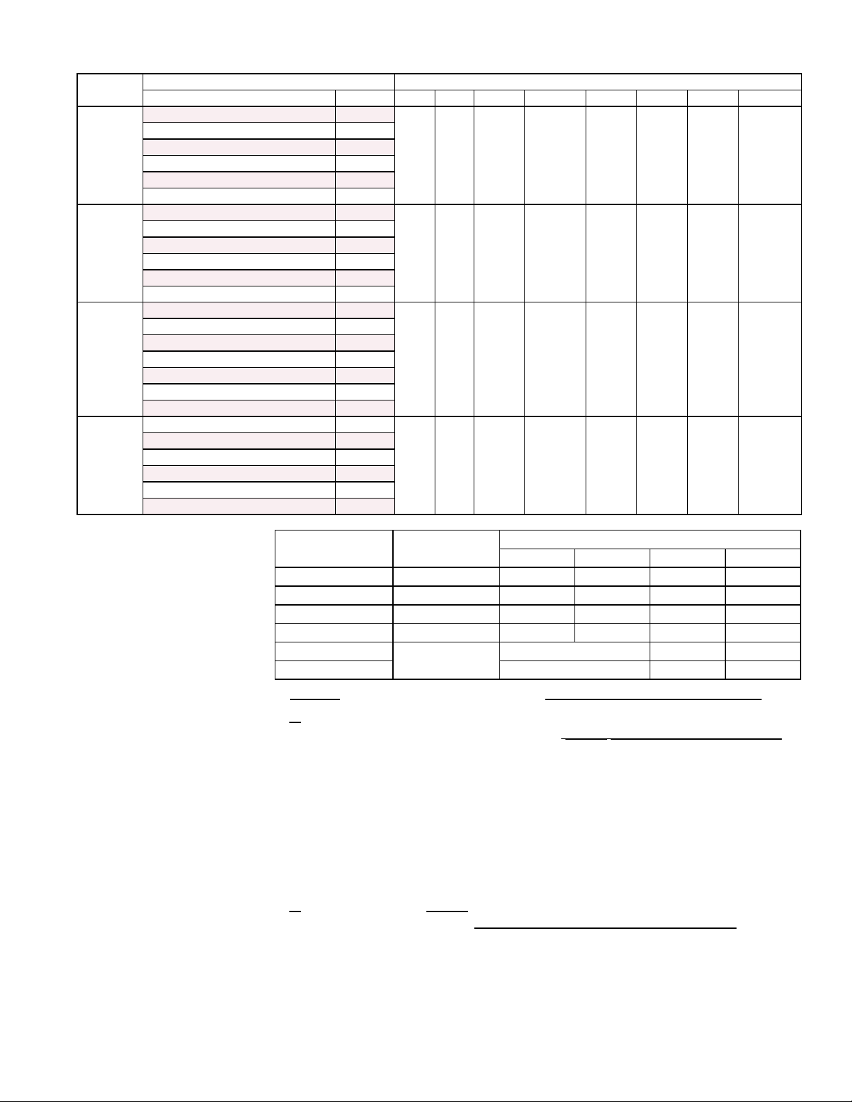
2.3 MAPSIII D
Cabinet Sizes
Model
RCB
360
480
600
720
Model
RDB
418
444
484
538
564
602
658
684
722
804
842
Cabinet
Size
D
Cabinet
Size
D
Model
RDCB
360
480
600
720
Model
RDDB
418
444
484
538
564
602
658
684
722
804
842
Gas Heat Section Size
-500 -600 -700 -800 -1000 -1200 -1400 -1600
D D D D D D D D
D D D D D D D D
D D D D D D D D
D D D D D D D D
Gas Heat Section Size
-500 -600 -700 -800 -1000 -1200 -1400 -1600
D D D D D D D D
D D D D D D D D
D D D D D D D D
D D D D D D D D
D D D D D D D D
D D D D D D D D
D D D D D D D D
D D D D D D D D
D D D D D D D D
D D D D D D D D
D D D D D D D D
Electric Heat Section
RECB120 RECB180
D D
D D
D D
D D
Electric Heat Section
REDB120 REDB180
D D
D D
D D
D D
D D
D D
D D
D D
D D
D D
D D
3.0 Maintenance/
Service
Procedures
3.1 Filters
The lter section is equipped with 4 inches of pleated disposable or permanent aluminum lters. To remove lters, open the door and slide lters out.
If equipped with permanent aluminum lters, there are sixteen 2"x20"x24" lters.
Remove the lters, wash, rinse, allow to dry, and slide them back in the cabinet. The
P/N for replacement or extra lter is 223065; quantity is 16.
If equipped with pleated disposable lters, there are eight 4"x20"x24" lters, either
MERV8 or MERV13.. Replace dirty lters. Exposure to humid makeup air can accelerate lter degradation. Systems with disposable lters require more frequent lter
inspection. The P/N for one replacement or extra MERV8 lter is 222480; quantity
required is 8. The P/N for one replacement or extra MERV13 lter is 260828; quantity
required is 8.
Dirty Filter Switch - If equipped with a dirty lter switch, check the condition of the
sensing tubes to be sure that they are not blocked. Check the wiring connections. To
set a new switch, see Installation Form I-MAPSIII&IV, Paragraph 8.1, Replacement
switch is P/N 105507.
Permanent Filters in
the Outside Air Hood
If equipped with an outside air hood, there are 1" permanent, aluminum lters at the
entrance of the hood. The lters act as a moisture eliminator and bird screen.
When inspecting the inlet air lters, inspect the outside air hood lters. If cleaning is
needed, remove the lters, clean, rinse, dry and re-install. NOTE: If it is more conve-
nient to keep an extra clean set of lters, lter sizes and part numbers are shown in
the illustration.
FIGURE 2 - Removing Filters
from Outside Air Hood
Form O-MAPSIII Cabinet D, P/N 222918R9, Page 5
Page 6
3.0 Maintenance/
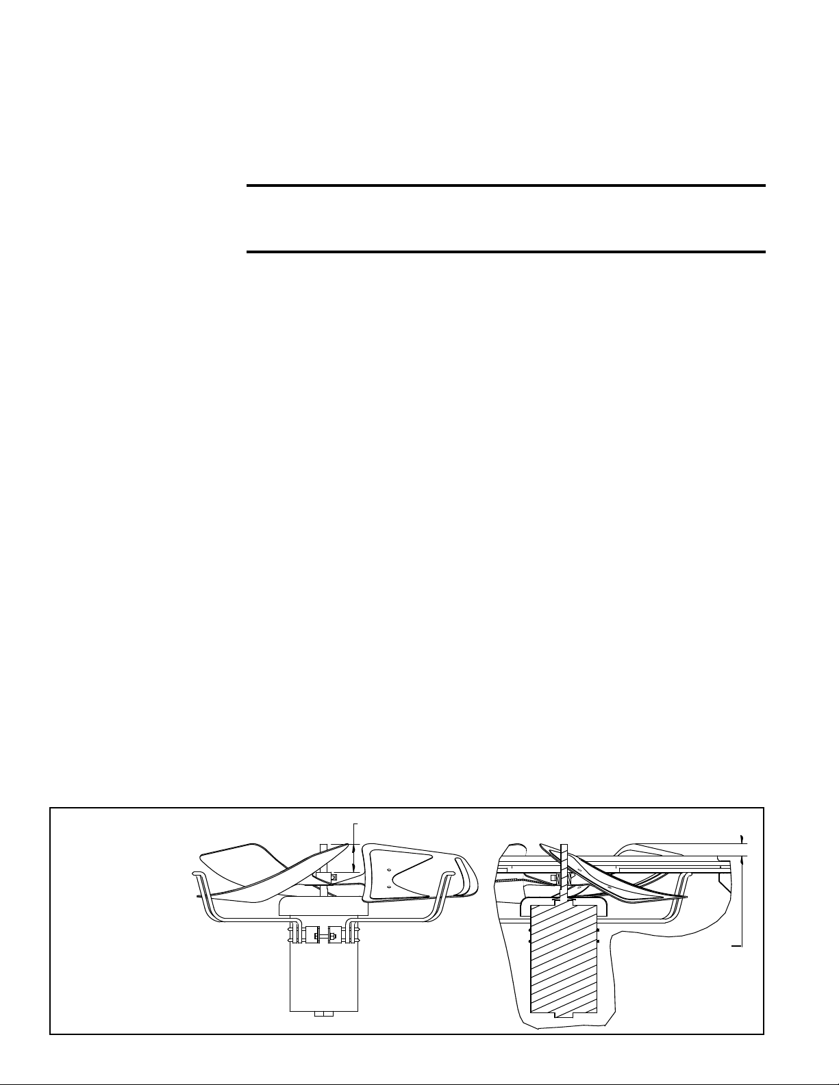
2-1/2” (63.5mm)
Fan and Motor Assembly
showing Fan Blade Position
Cross-section of Installed Fan and Motor
Assembly showing Cabinet Top
1.76” (44.7mm)
Top of Fan Blade
to Top of the
Cabinet Top Panel
Service
Procedures
(cont'd)
3.2 Drive Components
Bearings - Bearings with a grease tting should be lubricated twice a year with a high
temperature, moisture-resistant grease. (Type NLGI-1 or -2 standard grease is recommended.) Be sure to clean the grease tting before adding grease. Add grease with a
handgun until a slight bead of grease forms at the seal. Be careful not to unseat the
seal by over lubricating. NOTE: If unusual environmental conditions exist (tempera-
tures below 32°F or above 200°F; moisture; or contaminants), more frequent lubrication is required.
CAUTION: If the blower is unused for more than three months,
bearings with a grease tting should be purged with new grease
prior to start-up.
Setscrews - Check all of the setscrews (bearing/blower hubs and pulleys). Torque pul-
ley setscrews a minimum of 110 in-lb to 130 in-lb maximum.
A bearing hub setscrew for a 1-3/8" to 1-3/4" shaft requires a 5/16" socket and a tightening torque of 165 in-lbs.
Belts - Check belt for proper tension and wear. Adjust belt tension as needed. Replace
worn belts.
Blower systems are equipped with either Power Twist Plus
belt. The linked belts are designed in sections allowing for easy sizing and adjustment.
The belt is sized at the factory for the proper tension. If the belt needs adjustment, the
recommended method of shortening the belt length is to count the number of links and
remove one link for every 24. (A link is made up of two joining sections of belt. For easier removal of links, turn the belt inside out. But be sure to turn it back before installing.)
If equipped with a solid belt, adjust the belt tension by turning the adjusting screw on
the motor base until the belt can be depressed 1/2" (13mm) on each side. After correct
tension is achieved, re-tighten the locknut on the adjustment screw.
Proper belt tension is important to the long life of the belt and motor.
Be sure belts are aligned in the pulleys. If a belt is removed or replaced, be sure to align
directional arrows on the belt to the proper drive rotation.
Motor and Blower - Inspect the motor mounts periodically. Remove dust and dirt accumulation from the motor and wheel.
The blower has cast iron, pillowblock, sealed bearings. Under most operating conditions, re-lubrication is unnecessary. If lubrication is required, use a lubricant compatible to Shell Alvania #2 (lithium base - Grade 2). Operating temperature range is -30
to 230°F.
"D" size cabinets have plenum fan blowers which have an extension to the grease tting on the side of the fan assembly.
If any drive parts need to be replaced, use only factory-authorized replacements
designed for the application.
®
linked blower belt or a solid
3.3 Condenser Fans
FIGURE 3 -
Condenser
Fan Assembly
Dimensions
and Rotation
Form O-MAPSIII Cabinet D, P/N 222918R9, Page 6
Depending on the size, there are two, three, or four fans in the condenser section. If
parts need to be replaced, use only factory authorized replacement parts.
See FIGURE 3 for assembled dimensions and proper fan rotation direction.
Fan rotation
is clockwise
Page 7
3.4 Coil
Condenser Coils by Circuit
D
A
B
C
5 ton MC Coil
10 ton MC Coil
Inlet 1
Ø 0.879
Inlet 2
Ø 0.879
Outlet
Ø 0.879
Discharge
Line Ø 0.500
Discharge
Line Ø 0.875
Discharge
Line Ø 0.875
Liquid Line
Ø 0.875
Liquid Line
Ø 0.875
Liquid Line
Ø 0.500
Filter Drier
Filter Drier
Filter Drier
(See compressor locations on page 12.)
A
C
D
A
C
D
Suction Line Ø 1.375
Suction Line Ø 0.875
Suction Line Ø 1.375
RCB/RDCB/RECB 360 and
RDB/RDDB/REDB 418, 444, and 484
(To TXV valves and
Distributors on
Evaporator Coils)
15 ton MC Coil
Inlet
Ø 0.506
Outlet Ø 0.506
Inlet
Ø 0.879
Outlet Ø 0.879
Outlet Ø1.380
Outlet Ø1.380
Outlet Ø 0.879
Maintenance
Inspect all cooling system coils at the beginning of the cooling season or more often if
needed. Follow the cleaning instructions below. If additional cleaning is required or if a
coil must be removed for any reason, consult the factory. Be prepared to provide rating
plate and installation information.
Condenser Coil Access - The bank of condensing coils is located on top of the unit.
Condenser Coil Cleaning Instructions:
1) Verify that the electrical power has been turned off and the disconnect switch
locked.
2) Use a soft brush to remove any dirt and debris from the coils.
3) Spray with cold or warm (not hot) water and a cleaning solution (non-acid based
coil cleaner is recommended). Due to possible damage to the coil, do not use
high pressure spray.
4) When clean, rinse with cool, clean water.
Evaporator Coil Access - The evaporative coils can be accessed by opening the coil
cabinet door.
Inspect coils for debris, dirt, grease, lint, pollen, mold, or any element which would
obstruct heat transfer or airow. Inspect coils and tubing for physical damage. Inspect
feeders, piping connections, coil headers, and return bends for signs of fatigue, rubbing, and physical damage.
Clean the coils annually, or more often if needed. Use the proper tools and follow the
instructions carefully to avoid damaging the coil. Use of a non-acid based coil cleaner
is recommended. Due to possible damage to the coil, high pressure spray is not recommended.
FIGURE 4 - Coil Circuits (Views are from the control side of the system.)
Evaporator Coil Cleaning Instructions:
1) Verify that the electrical power has been turned off and the disconnect switch
locked.
2) Open the access panels.
3) Use a soft brush to remove any dirt and debris from both sides of a coil.
4) Spray with cold or warm (not hot) water and a cleaning solution (non-acid based
coil cleaner is recommended). Due to possible damage to the coil, high pressure
spray is not recommended. First spray the leaving airow side, then the inlet
airow side.
As much as possible, spray the solution perpendicular to the face of the coil.
Follow the instructions on the cleaning solution. When cleaning process is
complete, rinse both sides with cool, clean water.
Form O-MAPSIII Cabinet D, P/N 222918R9, Page 7
Page 8
3.0 Maintenance/Service Procedures (cont'd)
Condenser Coils by Circuit
Condenser Coils by Circuit
ADA
B
C
D
A
B
C
10 ton MC Coil
5 ton MC Coil
10 ton MC Coil
15 ton MC Coil
15 ton MC Coil
Inlet 1
Ø 0.881
Inlet 1
Ø 0.879
Inlet
Ø 0.881
Inlet 2
Ø 0.881
Inlet 2
Ø 0.879
Inlet 1
Ø 0.881
Inlet 2
Ø 0.881
Outlet
Ø 0.881
Outlet
Ø 0.881
Outlet
Ø 0.879
Outlet
Ø 0.881
Discharge
Line Ø 0.875
Discharge
Line Ø 0.875
Discharge
Line Ø 0.875
Discharge
Line Ø 0.500
Discharge
Line Ø 0.875
Discharge
Line Ø 0.875
Liquid Line Ø 0.875
Liquid Line
Ø 0.875
Liquid Line
Ø 0.875
Liquid Line
Ø 0.875
Liquid Line
Ø 0.500
Liquid Line Ø 0.875
Filter Drier
Filter Drier
Filter Drier
Filter Drier
Filter Drier
Filter Drier
A
D
B
C
Discharge
Line Ø 0.875
Discharge
Line Ø 0.875
Discharge
Line Ø 0.875
Discharge
Line Ø 0.875
Liquid Line
Ø 0.875
Liquid Line
Ø 0.875
Liquid Line Ø 0.875
Liquid Line Ø 0.875
Filter Drier
Filter Drier
Filter Drier
Filter Drier
Outlet
Ø 0.881
Outlet
Ø 0.881
Outlet
Ø 0.881
Outlet
Ø 0.881
Inlet
Ø 0.881
Inlet 2
Ø 0.881
Inlet 1
Ø 0.881
Inlet 2
Ø 0.881
Inlet 1
Ø 0.881
Inlet
Ø 0.881
10 ton MC Coil
10 ton MC Coil
15 ton MC Coil
15 ton MC Coil
(See compressor locations on page 12.)
(See compressor locations on page 12.)
(See compressor
locations on page 12.)
Evaporator Coils by
Circuit (interlaced)
Evaporator Coils by
Circuit (interlaced)
A
C
D
A
C
D
A
C
D
All three
outlets
Ø 1.380
All four
outlets
Ø 1.380
Suction Line Ø 1.375
Suction Line Ø 1.375
Suction Line Ø 0.875
Suction Line Ø 1.375
Suction Line Ø 1.375
Suction Line Ø 1.375
RCB/RDCB/RECB 480 and
RDB/RDDB/REDB 538, 564, and 602
RCB/RDCB/RECB 360 and
RDB/RDDB/REDB 418, 444, and 484
RCB/RDCB/RECB 600 and
RDB/RDDB/REDB 658, 684, and 722
A
B
D
C
Suction Line Ø 1.375
Suction Line Ø 1.375
Suction Line Ø 1.375
Suction Line Ø 1.375
(To TXV valves and
Distributors on
Evaporator Coils)
(To TXV valves and
Distributors on
Evaporator Coils)
(To TXV valves and Distributors
on Evaporator Coils)
Condenser Coils by Circuit
15 ton MC Coil
Inlet
Ø 0.506
Outlet Ø 0.506
Inlet
Ø 0.879
Outlet Ø 0.879
Outlet Ø1.380
Outlet Ø1.380
Outlet Ø 0.879
3.4 Coil Maintenance (cont'd)
FIGURE 4 (cont'd) - Coil Circuits (Views are from the control side of the system.)
RCB/RDCB/RECB 720 and
RDB/RDDB/REDB 722, 804, and 842
Evaporator Coils by
Circuit (interlaced)
A
C
D
B
All four
Form O-MAPSIII Cabinet D, P/N 222918R9, Page 8
outlets
Ø 1.380
Suction Line Ø 1.375
Suction Line Ø 1.375
Suction Line Ø 1.375
Suction Line Ø 1.375
Filter Drier
Filter Drier
Filter Drier
Filter Drier
on Evaporator Coils)
(To TXV valves and Distributors
A
15 ton MC Coil
Inlet 2
Ø 0.881
Inlet 1
Ø 0.881
Liquid Line
Ø 0.875
Liquid Line
Ø 0.875
(See compressor locations on page 12.)
Condenser Coils by Circuit
Inlet 1
D
Ø 0.881
15 ton
Inlet 2
Outlet
Ø 0.881
Discharge
Line Ø 0.875
Liquid Line Ø 0.875
Liquid Line Ø 0.875
MC Coil
Outlet
Ø 0.881
Ø 0.881
Discharge
Line Ø 0.875
Inlet 1
Ø 0.881
15 ton
MC Coil
Inlet 2
Ø 0.881
Discharge
Outlet
Ø 0.881
Line Ø 0.875
B
15 ton MC Coil
Outlet
Ø 0.881
C
Inlet 2
Ø 0.881
Inlet 1
Ø 0.881
Discharge
Line Ø 0.875
Page 9
3.5 Check
Refrigerant
Pressure and
Temperatures
(subcooling and
superheat)
DANGER
The refrigeration circuits are high pressure systems. Hazards
exist that could result in personal injury or death. Removal,
installation, and service of this scroll compressor must be
performed by a technician qualied in R-410A refrigerant.
DO NOT USE tools or service equipment designed for R22
refrigerant. See Hazard Levels, page 2.
Check SUBCOOLING
Measure and record temperature and pressure of the liquid line at the condenser coil
outlet.
STEP 1) Record Measurements: Temperature = ________°F (°C) and
Pressure = ________ psig
STEP 2) From Temperature/Pressure Conversion Chart (page 10), convert
Measured Pressure (STEP 1) to ________°F (°C)
STEP 3) Subtract Measured Temperature (STEP 1) from Temperature from
Conversion Chart (STEP 2): ________°F (°C) - ________°F (°C) =
________°F (°C) degrees of Subcooling
Recommended subcooling with outdoor temperature range of 70
to 95°F (21 to 35°C) is 10 to 12 degrees F (5.6 to 6.7 degrees C).
Too much subcooling indicates a refrigerant overcharge. To reduce the subcooling,
remove excess refrigerant. Too little subcooling indicates a refrigerant undercharge.
To increase subcooling, slowly add R-410A refrigerant.
WARNING
Do not release refrigerant to the atmosphere. When adding or removing
refrigerant, the qualied technician must comply with all national, state/
province, and local laws.
Determine SUPERHEAT
Measure and record temperature (insulate probe from surrounding air temperature)
and pressure in the suction line at the compressor inlet.
STEP 1) Record Measurements: Temperature = _______°F (°C) and Pressure
= _______ psig
STEP 2) From Temperature/Pressure Conversion Chart (below), convert
Measured Pressure (STEP 1) to ________°F (°C)
STEP 3) Subtract Measured Temperature (STEP 1) from Temperature from
Conversion Table (STEP 2): _______°F (°C) - ________°F (°C) =
________°F (°C) degrees of Superheat
Recommended superheat at is 8 to 12 degrees F (4.5 to 6.7
degrees C).
Typically, too much superheat indicates that the evaporator coil is undercharged.
Too little superheat typically indicates that the evaporator coil is overcharged and
may potentially ood liquid refrigerant to the compressor. To reduce the superheat,
adjust the thermal expansion valve by turning the adjusting stem counterclockwise.
To increase the superheat, adjust the thermal expansion valve by turning the adjusting stem clockwise.
Form O-MAPSIII Cabinet D, P/N 222918R9, Page 9
Page 10
3.0 Maintenance/Service Procedures (cont'd)
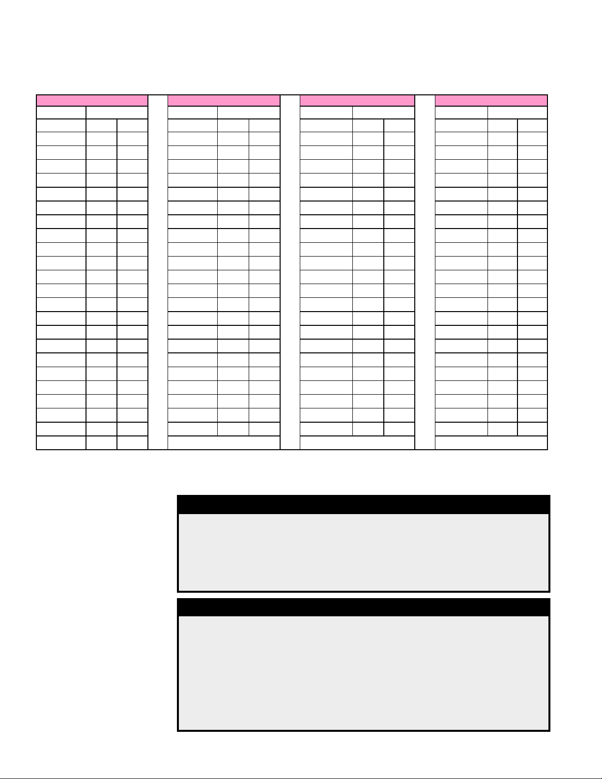
3.5 Check Refrigerant Pressure and Temperatures (subcooling and superheat)
(cont'd)
Temperature/Pressure Conversion Chart
R-410A Refrigerant R-410A Refrigerant R-410A Refrigerant R-410A Refrigerant
Pressure Temperature Pressure Temperature Pressure Temperature Pressure Temperature
PSI °F °C PSI °F °C PSI °F °C PSI °F °C
1.8 -55 -48.3 56.4 6 -14.4 93.5 28 -2.2 143.3 50 10.0
4.3 -50 -45.6 57.9 7 -13.9 95.5 29 -1.7 156.6 55 12.8
7.0 -45 -42.8 59.3 8 -13.3 97.5 30 -1.1 170.7 60 15.6
10.1 -40 -40.0 60.8 9 -12.8 99.5 31 -0.6 185.7 65 18.3
13.5 -35 -37.2 62.3 10 -12.2 101.6 32 0.0 201.5 70 21.1
17.2 -30 -34.4 63.9 11 -11.7 103.6 33 0.6 218.2 75 23.9
21.4 -25 -31.7 65.4 12 -11.1 105.7 34 1.1 235.9 80 26.7
25.9 -20 -28.9 67.0 13 -10.6 107.9 35 1.7 254.6 85 29.4
27.8 -18 -27.8 68.6 14 -10.0 110.0 36 2.2 274.3 90 32.2
29.7 -16 -26.7 70.2 15 -9.4 112.2 37 2.8 295.0 95 35.0
31.8 -14 -25.6 71.9 16 -8.9 114.4 38 3.3 316.9 100 37.8
33.9 -12 -24.4 73.5 17 -8.3 116.7 39 3.9 339.9 105 40.6
36.1 -10 -23.3 75.2 18 -7.8 118.9 40 4.4 364.1 110 43.3
38.4 -8 -22.2 77.0 19 -7.2 121.2 41 5.0 389.6 11 5 46.1
40.7 -6 -21.1 78.7 20 -6.7 123.6 42 5.6 416.4 120 48.9
43.1 -4 -20.0 80.5 21 -6.1 125.9 43 6.1 444.5 125 51.7
45.6 -2 -18.9 82.3 22 -5.6 128.3 44 6.7 474.0 130 54.4
48.2 0 -17.8 84.1 23 -5.0 130.7 45 7.2 505.0 135 57.2
49.5 1 -17.2 85.9 24 -4.4 133.2 46 7.8 537.6 140 60.0
50.9 2 -16.7 87.8 25 -3.9 135.6 47 8.3 571.7 145 62.8
52.2 3 -16.1 89.7 26 -3.3 138.2 48 8.9 607.6 150 65.6
53.6 4 -15.6 91.6 27 -2.8 140.7 49 9.4 645.2 155 68.3
55.0 5 -15.0
3.6 Compressor
Maintenance
and
Replacement
Form O-MAPSIII Cabinet D, P/N 222918R9, Page 10
The refrigeration circuits are high pressure systems.
Hazards exist that could result in personal injury or death. It
is therefore required that the removal and installation of this
scroll compressor be performed by a technician qualied in
R-410A refrigerant. See Hazard Levels, page 2.
Never use oxygen to pressurize a refrigeration system. Oxygen
can explode on contact with oil and could result in personal injury
or death. When using high pressure gas such as nitrogen for
this purpose, ALWAYS USE A PRESSURE REGULATOR that can
control the pressure down to 1 or 2 psig. Failure to use a regulator
will result in extremely high pressure which could exceed the
burst pressure of the compressor or other system components
and result in personal injury or death. See Hazard Levels, page 2.
DANGER
DANGER
Page 11
WARNINGS
For your safety, wear eye protection, gloves, and protective clothing
when handling refrigerant and oil and when brazing. Have a re
extinguisher nearby. See Hazard Levels, page 2.
Compressor Handling
Do not lift compressor by copper tubing. To prevent internal damage, compressors
must ALWAYS be held upright.
The following instructions include major points of consideration that will ensure proper
installation and protect you from potential personal injury. Please use the following 13
steps as a checklist, taking each item in order before proceeding to the next. If more
information is required, contact the Reznor Service Department for Reznor® products.
WARNING
To avoid electrical shock, power to the com-pressor(s) MUST REMAIN
OFF during performance of Steps 1 through 9 below. LOCK DISCONNECT
SWITCH OFF (open).
Step 1. Verify Proper Application
Verify that the replacement compressor is identical to the model being replaced.
All system components are matched to the compressor. Replacing a compressor
with a model other than the one specied for replacement will void the product
warranty. See part numbers for R-410A compressors on page 13.
Step 2. Determine Cause of Initial Failure and Remove the
Compressor
In order to prevent a second failure, the cause of the original failure must be
determined. Identify the cause and make the necessary repairs.
CAUTION: DO NOT LIFT compressor by copper tubing; damage will
occur. Compressor must remain upright.
WARNING
Wear eye protection and gloves when handling refrigerant or oil and
when brazing.
a) BEFORE REMOVING THE FAULTY COMPRESSOR, remove refrigerant charge
using proper recovery procedures. Call 1-800-441-9450 for the name of the nearest
Dupont authorized distributor or 1-800-ASK-KLEA (IGI) for information on their refrigerant reclaim programs.
b) Disconnect wires. All compressor wiring is connected using a black molded
plastic plug. Remove the plug from the compressor.
c) Open access ports so that pressure does not build up in the system. Before
unbrazing stubs from the compressor, cut suction and discharge tubing with a
tubing cutter.
WARNING
Have a re extinguisher near. The compressor contains oil. There is a
risk of re when unbrazing stubs.
Use a high temperature torch to disconnect the suction line and the discharge line from
the compressor.
d) Remove the mounting bolts and the compressor. Save the mounting hardware
to attach the grommets and sleeves shipped with the replacement compressor.
e) To test for acid and to assure excess oil does not remain in the circuit, remove
oil from the failed compressor. Measure the amount of oil.
CAUTION: In addition to the required eye protection and gloves, care
should be taken in handling POE oil because it may cause damage to
certain plastics and roong materials. See Hazard Levels, page 2.
Form O-MAPSIII Cabinet D, P/N 222918R9, Page 11
Page 12
3.0 Maintenance/
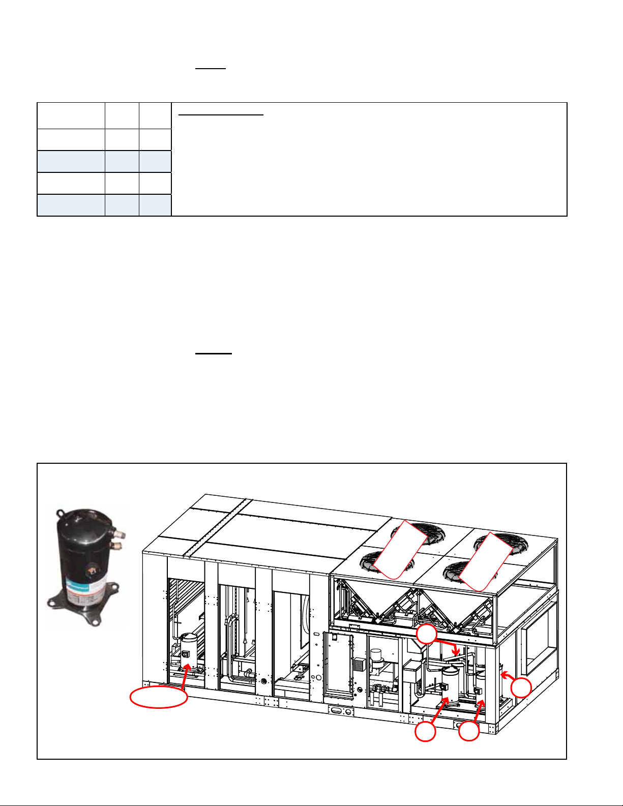
Reheat compressor in
Models RDB and RDDB
A
C
B
DH or E
D
Condenser
Bank B & C
Condenser
Bank A & D
Service
Procedures
(cont'd)
3.6 Compressor Maintenance (cont'd)
Step 2. Determine Cause of Initial Failure (cont'd)
Compressor Oil Charge (POE Oil)
Compressor
Model
ZP57K3E 1538 52
ZP83KCE 1656 56
ZP120KCE 3135 106
ZP182KCE 3135 106
cc oz
Important NOTES: These R-410A compressors use a polyolester (POE)
lubricant. Types of recommended POE oil are Copeland Ultra 22 CC, Copeland Ultra
32 CC, Copeland Ultra 32-3MAF, Mobil EAL™, Arctic 22 CC, Uniqema Emkarate RL32CF,
or Uniqema RL32-3MAF.
POE oil absorbs moisture much quicker and to a greater degree than standard
mineral oil. The compressor must not be left open longer than 15 minutes
during replacement. During installation the system must be swept with an inert
gas such as dry nitrogen to keep moisture from entering the compressor and
prevent the formation of oxides.
If the oil taken from the compressor and measured is found to be signicantly
lower than listed in the table above, clean the excess oil through use of suction
and liquid line lter driers. Beginning in Step 4, follow the same procedure
as for burnout cleanup.
Use an acid test kit to check the oil for acid. If acid is found, beginning in
Step 4, follow procedures indicated for burnout cleanup.
Dispose of oil and compressor using an approved environmentally safe
disposal method.
□ Step 3. Mount the Replacement Compressor
Do not remove the dust cover or rubber shipping plugs until all other system
connections are complete (i.e. new liquid line lter drier(s) installed and all tubing
changes made - see Steps 4 and 5). The amount of time the compressor is open
to the atmosphere must be kept to a minimum.
Use the new mounting grommets and sleeves that are shipped with the
compressor to mount it. The sleeves will prevent over compression of the
grommets. Re-use the mounting bolts from the compressor that was removed. The
mounting bolts will bottom out when tight.
FIGURE 5 - Identication of Compressors by Location
Compressor
Form O-MAPSIII Cabinet D, P/N 222918R9, Page 12
Page 13
Compressor Staging for Cooling (applies to Models RCB, RDB, RDCB, RDDB RECB, REDB)
MAPSIII
Cabinet D
360
418
444
484
480
538
564
602
600
658
684
722
720
804
842
DH or E (RDB/RDDB/REDB 418) 5
DH or E (RDB/RDDB/REDB 444) 7
DH or E (RDB/RDDB/REDB 484) 10
DH or E (RDB/RDDB/REDB 538) 5
DH or E (RDB/RDDB/REDB 564) 7
DH or E (RDB/RDDB/REDB 602) 10
DH or E (RDB/RDDB/REDB 658) 5
DH or E (RDB/RDDB/REDB 684) 7
DH or E (RDB/RDDB/REDB 722) 10
DH or E (RDB/RDDB/REDB 804) 7
DH or E (RDB/RDDB/REDB 842) 10
Compressor Cooling Staging
Circuit Tonnage 1 2 3 4 5 6 7 8
A 10
C 5
D 15
A 10
C 15
D 15
A 10
B 10
C 15
D 15
A 15
B 15
C 15
D 15
C A A+C D C+D A+C+D
A D A+D C+D A+C+D
B D A+B A+D C+D A+B+D B+C+D A+B+C+D
B B+C B+C+D A+B+C+D
Compressor Model
and P/N by Tonnage
and Voltage
Compressor
Model
ZP57K3E 5 216686 216686 216687 216688
ZP83KCE 7 216689 216689 216690 216691
ZP120KCE 10 216695 216695 216696 216697
ZP182KCE
Wiring Harness
Crankcase Heater P/N 216402 P/N 216404 P/N 216405
ARI Tonnage
15 216454 216454 216455 216456
One each for each
compressor
208V 230V 460V 575V
P/N 223028 P/N 223029 P/N 223030
Compressor P/N
□ Step 4. Install New Filter Driers (Select procedure that applies.)
IF the oil measured in Step 2 was not signicantly less than the amount shown
in the table on page 12 or the test for acid in Step 2 did NOT indicate burnout ,
install a new R-410A refrigerant liquid line lter drier. The lter drier must be rated
for no less than 600 psig and be the proper size for the circuit. Because R-410A
refrigerant requires POE oil which absorbs moisture quickly, it is important to
change the lter drier any time the circuit is opened.
It is recommended to use a tubing cutter when cutting out a lter drier as the
desiccant absorbs and holds moisture better when it is cool. Heat from a torch may
cause moisture to leave the lter and be absorbed in the oil. Be careful to keep
dirt, lings, and other contaminants out of the system.
Continue to Step 5.
IF the oil measured in Step 2 was signicantly less than shown in the table on
page 12 or the test for acid in Step 2 did indicate compressor burnout, do the
following:
a) Install a liquid line lter drier. If there is acid, install an acid removing lter drier.
Size the acid-removing lter drier at least one capacity size larger than normally
required for the circuit.
b) Install a temporary lter drier in the suction line. When there is acid, a 100%
activated alumina suction lter drier is recommended. The suction line drier
should be sized properly for the circuit and have a service access tting to
Form O-MAPSIII Cabinet D, P/N 222918R9, Page 13
Page 14
3.0 Maintenance/
Service
Procedures
(cont'd)
3.6 Compressor
Maintenance
(cont'd)
□ Step 4. Install New Filter Driers (cont'd)
monitor pressure drop across the drier. (NOTE: Suction line lter drier must be
removed after 72 hours of operation.)
Step 12 includes the remaining procedures required for cleanup of a burnout.
Continue to Step 5.
□ Step 5. Braze on Suction and Discharge Lines
CAUTION; Do not leave system open to the atmosphere any
longer than minimum required for installation. POE oil in the
compressors is extremely susceptible to moisture absorption.
Always keep ends of tubing sealed during installation. See Hazard
Levels, page 2.
Brazing materials must be able to withstand the high pressure of R-410A refrigerant.
A high temperature, silver phosphate type brazing with 5% or greater alloy is recommended.
To prevent oxidation, purge tubing with 2-3 psig of regulated dry nitrogen while it is
being brazed. Open the service valve as needed to release the nitrogen. Do not allow
moisture to enter the system.
The installer is responsible for brazing and for complying with appropriate standard
refrigerant piping procedures.
CAUTION: All brazing should be done using a 2 to 3 psig dry
nitrogen purge owing through the pipe being brazed. See Hazard
Levels, pg 2.
CAUTION: When brazing, protect all painted surfaces and
components from excessive heat. Wet wrap all valves but do not
allow moisture to enter the tubing. See Hazard Levels, page 2.
□ Step 6. Check System for Leaks
After installation is complete, pressurize the circuit to approximately 75 psig using
nitrogen and a few ounces of refrigerant. Check for leaks using soap bubbles or
other leak-detecting methods.
□ Step 7. Evacuate the Circuit
Evacuate one circuit at a time. Use a vacuum pump and micron gauge. Each
circuit must be evacuated to hold a 500 micron vacuum. Vacuum must be pulled
on both the discharge (high) and suction (low) side. Do the suction side rst; and
the compressor discharge side second. To establish that a circuit is leak-free
and moisture-free, a standing vacuum test is recommended. Close off the valve
to the vacuum pump and observe the micron gauge. If the vacuum gauge does
not rise above 500 microns in one minute, the evacuation should be complete.
If the vacuum gauge does rise above 500 microns in one minute, evacuation
is incomplete or the circuit has a leak. Repeat as needed until evacuation is
complete. The evacuation process must be done on each circuit.
NOTE: Evacuation will not remove moisture from POE oil. Moisture must be
prevented from getting in the oil.
Continue and/or repeat Steps 6 and 7 until evacuation is complete.
CAUTION: Do not use the replacement compressor as an
evacuation assist and never apply voltage to a compressor while
it is in a vacuum. See Hazard Levels, page 2.
Moisture and air are harmful to the system because they increase the condensing
temperature, raise the discharge gas temperature, cause formation of acids, and
cause oil breakdown.
Form O-MAPSIII Cabinet D, P/N 222918R9, Page 14
Page 15

CAUTION: Do not leave a circuit open to the atmosphere any
longer than minimum required for installation. POE oil in the
compressor is extremely susceptible to moisture absorption.
Evacuation will not remove moisture from POE oil.
□ Step 8. Check the Electrical System
After the system has been evacuated, reconnect the electrical plug to the compressor
or the wires to the compressor terminals. It is a normal practice to replace all starting
components any time a compressor is changed.
WARNING
Do not apply voltage to the compressor when the plug is
removed or terminals disconnected.
Crankcase Heater - Connect the crankcase heater. The crankcase heater is ener-
gized continuously and is extremely important to proper compressor operation and
long life.
The crankcase heater must be energized for at least 24 hours before starting the unit
or after a power outage of more than 8 hours. Be sure to disable cooling controls
before turning on power to warm up crankcase heaters.
CAUTION: Crankcase heaters must be allowed to warm up for
at least 24 hours prior to startup. Disable cooling controls before
turning on power to warm up crankcase heaters.
□ Step 9. Charge the System (Use R-410A refrigerant only.)
Refer to the table on page 16 for the approximate amount of refrigerant required
and follow the instructions below to charge the circuit. R-410A refrigerant MUST
BE charged as a LIQUID.
NOTE: Outdoor temperature must be between 70-95°F (21-35°C) for verifying
superheat and subcooling. If temperature is not within this range, consult the
factory service department before charging.
If equipped with an optional hot gas bypass valve, disable the hot gas bypass
valve before charging. The method of disabling the bypass valve depends
on whether or not there is a shutoff valve in the line between the compressor
discharge and the hot gas bypass valve.
If there is a shutoff valve in the line between the compressor discharge and the
hot gas bypass valve, close the shutoff valve. When measurements are complete,
open the valve.
If there is not a shutoff valve in the line between the compressor discharge and
the hot gas bypass valve, disable the bypass by removing the cover from the
bypass valve and adjusting the spring tension. Count and record the number of
counterclockwise turns until the spring tension is relieved. (When ready to return
the bypass valve to its original setting, turn the spring the same number of turns
clockwise. To check setting, see instructions in Paragraph 3.9.5.)
IMPORTANT: Do not release refrigerant to the atmosphere! If
required service procedures include the adding or removing
of refrigerant, the qualied HVAC service technician must
comply with all federal, state or provincial, and local laws.
Liquid charge the high side to 80%. With the system running, add the balance of
the charge to the correct superheat and subcooling values. Refer to Step 11, page
17, and the instructions in Paragraph 3.5, page 9.
Form O-MAPSIII Cabinet D, P/N 222918R9, Page 15
Page 16

3. Maintenance/
Service
Procedures
(cont'd)
3.6 Compressor
Maintenance
(cont'd)
□ Step 9. Charge the
System (cont'd))
Approximate R410-A Refr
igerant Charge (lbs) by Model Size and
Compressor for Each Circuit (See FIGURE 5, page 12, to identify location.)
D Cabinet Models
and Size
RCB/RDCB/RECB 360 10.0 N/A 13.0 6.0 N/A
RCB/RDCB/RECB 480 10.0 13.0 13.0 N/A N/A
RCB/RDCB/RECB 600 10.0 10.0 13.0 13.0 N/A
RCB/RDCB/RECB 720 13.0 13.0 13.0 13.0 N/A
RDB/RDDB/REDB 418 10.0 N/A 13.0 6.0 9.0
RDB/RDDB/REDB 444 10.0 N/A 13.0 6.0 9.0
RDB/RDDB/REDB 484 10.0 N/A 13.0 6.0 11.0
RDB/RDDB/REDB 538 10.0 13.0 13.0 N/A 9.0
RDB/RDDB/REDB 564 10.0 13.0 13.0 N/A 9.0
RDB/RDDB/REDB 602 10.0 13.0 13.0 N/A 11.0
RDB/RDDB/REDB 658 10.0 10.0 13.0 13.0 9.0
RDB/RDDB/REDB 684 10.0 10.0 13.0 13.0 9.0
RDB/RDDB/REDB 722 10.0 10.0 13.0 13.0 11.0
RDB/RDDB/REDB 804 13.0 13.0 13.0 13.0 9.0
RDB/RDDB/REDB 842 13.0 13.0 13.0 13.0 11.0
A B C D E or DH
Compressor Circuit
□ Step 10. System Startup
Assure voltage to compressor does not drop below minimum allowable voltage
(e.g. 187 volts for 230/208-3-60, 415 volts for 460/3/60, 518 volts for 575/3/60)
during the period the compressor is trying to start. If a low voltage or voltage
imbalance condition exists, the electrical problem must be determined and
corrected prior to operating the unit.
Voltage Imbalance - Voltage imbalance is becoming a more common problem.
In a 3-phase system, excessive voltage imbalance between phases will cause
motors to overheat and compressors to fail. Maximum allowable imbalance is
2%. To determine voltage imbalance, measure and record the voltage of all three
phases. Take the measurements at the compressor terminals with the compressor
operating.
Voltage Imbalance Formula:
Key:
Formula:
If the imbalance is within the 2% tolerance, voltage imbalance is not a problem and
the system may be operated. If the imbalance exceeds the 2% tolerance, follow
the procedures below.
Solutions to Voltage Imbalance:
The cause for a voltage imbalance problem can originate at the power company or
can be caused inside the building. Try the following on-site solution to determine if
the problem can be easily resolved.
Roll the connections at the compressor terminals one forward. Connect the wire
now on Terminal 1 to Terminal 2, 2 to 3, and 3 to 1. Re-measure and re-calculate
the voltage imbalance. If the imbalance is within 2%, the system may be operated.
If the imbalance is not within tolerance, roll the connections one more forward.
Re-measure and re-calculate the voltage imbalance. If the imbalance is within
2%, the system may be operated. If the voltage imbalance still exceeds 2%, do
not start the system. Contact the building owner or person responsible to have an
electrician analyze the buildings's power supply and load distribution.
Power Supply Voltage Phasing - Connect refrigerant pressure gauges to the
suction and discharge lines of the compressors and an electric meter to the power
supply.
V1, V2, V3 = line voltages as measured
VA (Average )= (V1 + V2+ V3) / 3
VD = Line Voltage (V1, V2, or V3 that deviates farthest from average (VA)
% of Voltage Imbalance = [100 (VA - VD)] / VA
Form O-MAPSIII Cabinet D, P/N 222918R9, Page 16
Page 17

CAUTION: Be sure to connect pressure gauges to the suction
and discharge lines before system start-up so that compressor
rotation can be checked immediately. Scroll compressors will be
destroyed if allowed to operate in the wrong direction. See Hazard
Levels, page 2.
Record the ambient temperature. Adjust the system controller so that a call for
cooling exists.
NOTE: Outdoor ambient lockouts may prevent mechanical cooling. Temporarily
override lockouts by lowering the cooling setpoint. When testing is complete, reset
the controller.
Because it is possible to unknowingly connect 3-phase power in such a way
as to cause the scroll compressor or blower to rotate in reverse, it is very
important to check this on startup.
Check Compressors - Immediately at startup, observe the gauges. If the
suction pressure rises and discharge pressure drops, the compressor is
operating in reverse and must be shut down. Turn off the power and switch
the 3-phase line voltage wiring connections before restarting the unit.
(Important NOTE: If allowed to operate for several minutes in reverse, the
compressor’s internal protector will trip. If a compressor is repeatedly
allowed to restart and run in reverse, the compressor will be permanently
damaged.)
□ Step 11. Check Subcooling and Superheat
Superheat is the verication that the evaporator coil is properly using the
refrigerant supplied. Too much superheat indicates that the coil is undercharged.
Too little superheat indicates that the coil is overcharged and potentially ooding
liquid refrigerant to the compressor.
Subcooling is the measurement of liquid refrigerant stored in the condenser
coil. Too much subcooling indicates a system overcharge. Too little subcooling
indicates a system undercharge and may not provide the thermal expansion valve
with a full column of liquid refrigerant for proper operation.
Two important requirements before checking superheat and subcooling:
1) This unit has fully intertwined refrigerant circuits and each circuit MUST be
isolated before measuring its temperature. Another active circuit will inuence the
reading and make it impossible to determine accurate superheat and subcooling.
2) If equipped with an optional hot gas bypass, disable the hot gas bypass valve
before charging. The method of disabling the bypass valve depends on whether or
not there is a shutoff valve in the line between the compressor discharge and the
hot gas bypass valve.
If there is a shutoff valve in the line between the compressor discharge and the
hot gas bypass valve, close the shutoff valve. When measurements are complete,
open the valve.
If there is not a shutoff valve in the line between the compressor discharge and
the hot gas bypass valve, disable the bypass by removing the cover from the
bypass valve and adjusting the spring tension. Count and record the number of
counterclockwise turns until the spring tension is relieved. (When ready to return
the bypass valve to its original setting, turn the spring the same number of turns
clockwise. To check setting, see instructions in Paragraph 3.9.5.)
IMPORTANT: Do not release refrigerant to the atmosphere! If
required service procedures include the adding or removing
of refrigerant, the qualied HVAC service technician must
comply with all federal, state or provincial, and local laws.
Form O-MAPSIII Cabinet D, P/N 222918R9, Page 17
Page 18

3. Maintenance/
Service
Procedures
(cont'd)
3.6 Compressor
Maintenance
(cont'd)
□ Step 11. Check Subcooling and Superheat. (cont'd)
Follow the procedures in Paragraph 3.5 to check subcooling and superheat.
□ Step 12. (Select the procedure that applies.)
IF the oil measured in Step 2 was signicantly less than in the table on
page 12 or the acid test in Step 2 indicated a burnout, do the following:
a) Operate the unit for several hours. Check the pressure drop through the
temporary suction line lter drier. If the pressure drop exceeds 8 psig, recover
the refrigerant, replace the suction line lter drier with the same type as
removed, replace the liquid line lter drier, evacuate the circuit, and re-charge
with the recovered refrigerant.
Continue to monitor the pressure drop through the suction line lter drier and
repeat the process above until the pressure does not exceed 8 psig after
several hours of operation. (NOTE: System must be allowed to run no more
than 72 hours with a suction line lter drier.)
b) Allow the system to operate for 4-8 hours. Recover the refrigerant and take an
oil sample. Retest the oil for acid.
c) If the test for acid is negative, remove the suction line lter drier, replace
the liquid line drier, evacuate, and re-charge the system with the recovered
refrigerant.
If the test indicates acid, replace both the liquid line lter drier and the suction
line lter drier and repeat b) and c).
CAUTION: After cleanup is complete, remove the suction line
lter drier. See Hazard Levels, page 2.
3.7 Thermostatic
Expansion
Valves
d) Verify subcooling and superheat (refer to Step 11).
e) When the system is operating properly, remove the gauges.
IF the oil measured in Step 2 was not signicantly less than that shown
in the table on page 12 or the acid test in Step 2 did not indicate a
compressor burnout, continue to the review in Step 13.
□ Step 13 . Review ALL Steps to ensure that nothing was
overlooked.
All refrigeration circuits have a thermostatic expansion valve. Thermostatic expansion
valves (TXV's) do not have replaceable parts. If a replacement valve is required, it
must be an R410-A valve and be sized correctly for the application. All refrigerant ser-
vice should be performed by a technician qualied in R410-A refrigerant.
Replacement valves by size and circuit are listed in the following table.
Model & Size Compressor Circuit P/N Sporlan No. Connection Sizes
A 220556 BBIZE-8-GA 5/8x7/8x1/4
RCB/RDCB/RECB
360
RDB/RDDB/REDB
418/444/484
RCB/RDCB/RECB
480
RDB/RDDB/REDB
538/564/602
E or DH (RDB/RDDB/REDB 418 only) 234987 BBIZE-4-GA 1/2x7/8x1/4
E or DH (RDB/RDDB/REDB 444 only) 220555 BBIZE-6-GA 5/8x7/8x1/4
E or DH (RDB/RDDB/REDB 484 only) 220556 BBIZE-8-GA 5/8x7/8x1/4
E or DH (RDB/RDDB/REDB 538 only) 234987 BBIZE-4-GA 1/2x7/8x1/4
E or DH (RDB/RDDB/REDB 564 only) 220555 BBIZE-6-GA 5/8x7/8x1/4
E or DH (RDB/RDDB/REDB 602 only) 220556 BBIZE-8-GA 5/8x7/8x1/4
C 234987 BBIZE-4-GA 1/2x7/8x1/4
D 220558 BBIZE-15-GA 7/8x1-1/8x1/4
A 220556 BBIZE-8-GA 5/8x7/8x1/4
C 220558 BBIZE-15-GA 7/8x1-1/8x1/4
D 220558 BBIZE-15-GA 7/8x1-1/8x1/4
Form O-MAPSIII Cabinet D, P/N 222918R9, Page 18
Page 19

Model & Size Compressor Circuit P/N Sporlan No. Connection Sizes
A 220556 BBIZE-8-GA 5/8x7/8x1/4
B 220556 BBIZE-8-GA 5/8x7/8x1/4
RCB/RDCB/RECB
600
RDB/RDDB/REDB
658/684/722
RCB/RDCB/RECB
720
RDB/RDDB/REDB
804/842
E or DH (RDB/RDDB/REDB 658 only) 234987 BBIZE-4-GA 1/2x7/8x1/4
E or DH (RDB/RDDB/REDB 684 only) 220555 BBIZE-6-GA 5/8x7/8x1/4
E or DH (RDB/RDDB/REDB 722 only) 220556 BBIZE-8-GA 5/8x7/8x1/4
E or DH (RDB/RDDB/REDB 804 only) 220555 BBIZE-6-GA 5/8x7/8x1/4
E or DH (RDB/RDDB/REDB 842 only) 220556 BBIZE-8-GA 5/8x7/8x1/4
C 220558 BBIZE-15-GA 7/8x1-1/8x1/4
D 220558 BBIZE-15-GA 7/8x1-1/8x1/4
A 220558 BBIZE-15-GA 7/8x1-1/8x1/4
B 220558 BBIZE-15-GA 7/8x1-1/8x1/4
C 220558 BBIZE-15-GA 7/8x1-1/8x1/4
D 220558 BBIZE-15-GA 7/8x1-1/8x1/4
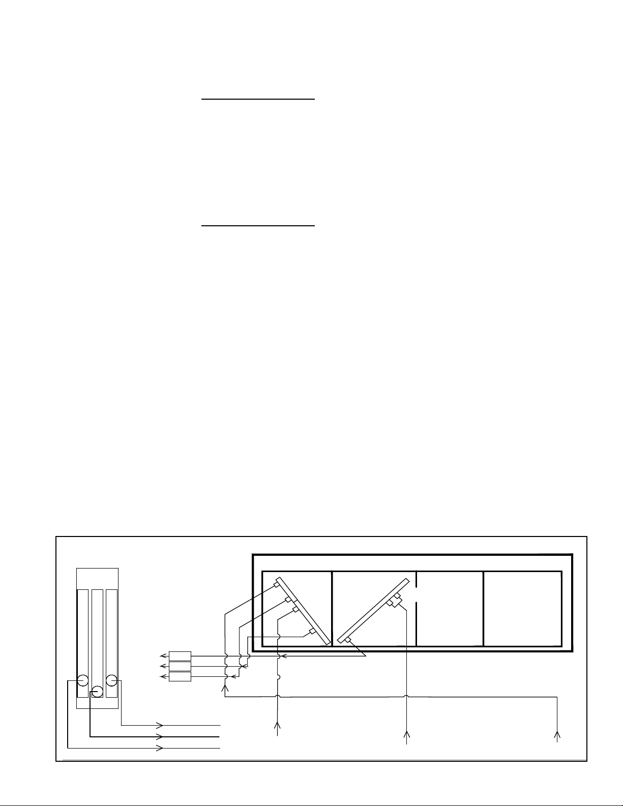
3.8 Dampers
and Damper
Controls
Damper Motor
Service: Other than external cleaning, there is no service required on the dampers or
the damper motor. If the damper, control, or motor need to be replaced, replace with a
factory-authorized replacement.
For additional information on damper controls (Options GF 1-9), see the system installation manual Form I-MAPSIII Cabinet D.
Inlet Air Dampers
Location: Dampers and damper motors are located in the inlet air opening.
Function: Dampers operate in response to the control selected. Damper controls are
shown below.
Service: Clean dampers and controls of dust and dirt.
2-Position Damper Motor (Option AR8)
Function: The 2-position damper motor opens and closes the dampers in response to
unit operation or a eld-supplied time clock.
Motor closes dampers on heater shutdown.
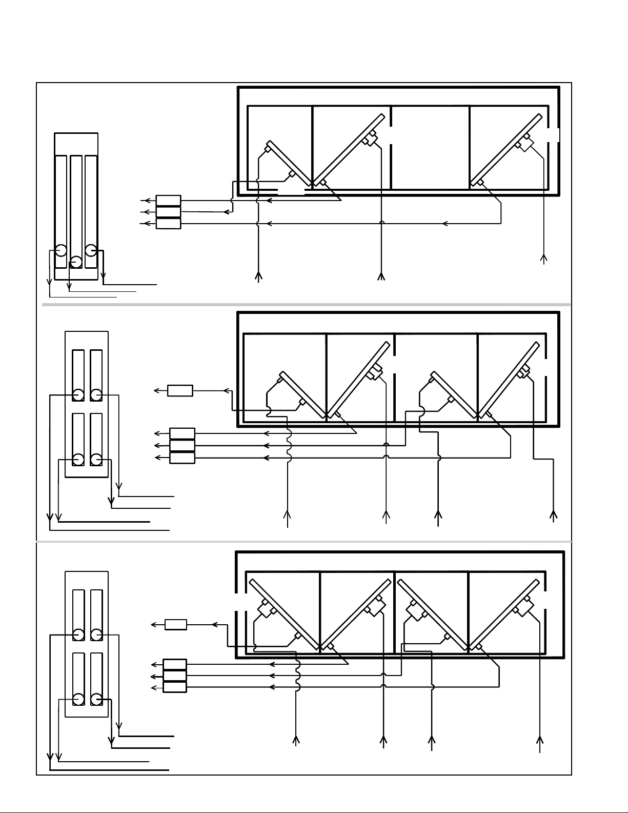
Modulating Motor (Option AR25)
Function: The modulating damper motor actuates the dampers in response to I/Q
control with actuation from input switch settings, a remote potentiometer, building pressure, CO2, 2-position outside air enthalpy, or dual reference enthalpy. Motor closes
dampers on heater shutdown.
3.9 Other Controls
NOTE: Refer to Control
Instruction Form
CP-MAPSIII D15/D16
for information on the
programmable controller.
Other factory-installed standard and optional controls are illustrated below. Find their
location in FIGURE 1, page 4. Cleaning external dirt is the only service procedure. If
any need to be replaced, use only factory-authorized replacement parts.
3.9.1 Programmable Digital Controller and Sensors
Display
I/Q System
Controller
All MAPSIII systems have a unit-mounted,
24-volt programmable I/Q controller.
Depending on how it was ordered, the system
is equipped for either neutral air/discharge air
control (Option D15) or space control with
discharge air reset (Option D16). The controller is factory programmed to match the selection. See the control instruction manual for
more information.
Some sensors are standard and others will
depend on option selection.
Form O-MAPSIII Cabinet D, P/N 222918R9, Page 19
Page 20

Outside
Air
Return
Air
Mixed Air Averaging
Sensor (between
filters and coil)
Return Air
Sensor
Temperature/
Humidity
Outside
Air Sensor
Temperature/
Humidity
Filters
Dirty Filter Switch Sensor
(entering air side)
Dirty Filter Switch Sensor
(leaving air side)
Coils
Air Proving
Switch Tap
Heat
Section
Discharge Temperature
Sensor (field installed)
Discharge
Temperature
Sensor (field
installed)
Vertical
Discharge
Horizontal
Discharge
Condenser Section
3.0 Maintenance Procedures (cont'd)
3.9 Other Controls (cont'd)
3.9.1 Programmable Digital Controller and Sensors (cont'd)
FIGURE 6 - Airow and Sensor Locations
Service: If a sensor needs to be replaced, use only a factory authorized replacement
part designed for the purpose. Refer to the digital wiring requirements in Paragraph 7.4
of Installation Form I-MAPSIII&IV).
If a controller needs to be replaced, it must be replaced with the same controller and
software.
3.9.2 Air Proving
Switch
3.9.3 Motor Starter
(Option AN10) or
Variable Frequency
Drive (Option VFD1 or
VFD2)
3.9.4 Voltage
Protection,
Option PL4
3.9.5 Hot Gas Bypass
Valve, Option AUC9
Form O-MAPSIII Cabinet D, P/N 222918R9, Page 20
Bypass
valve
Function: The airow proving switch is a pressure switch that veri-
es to the main controller that the blower (plenum fan) is operating.
Service: If the switch needs to be replaced, use a factory-authorized
replacement designed for the application.
Function: When the main controller calls for blower operation, either an IEC type
starter with a contactor or a variable frequency drive module responds to operate the
motor.
The starter is in the high voltage control compartment. The variable frequency drive
was eld installed in a location that is no more than 50 feet (15M) away where the
minimum temperature is 18°F (-9°C). Control of the variable frequency drive module is
coordinated with the main controller, and depending on what was ordered, can function
in response to temperature, CO2, or pressure controls.
Service: If a starter or contactor need replaced, use only the identical replacement that
is designed to match the motor and voltage of the system.
If a VFD needs to be replaced, contact the factory service department. Be prepared to
provide the model, serial, and wiring diagram numbers.
Function: Phase loss and low or high voltage can cause damage to electrical components. This safety control monitors phase loss and voltage and shuts down the unit
when its limits are exceeded. The device is auto reset and allows the unit to restart
when the power conditions are corrected.
Function: The hot gas bypass valve allows some of the refrigerant gas from the suction line to be re-routed directly to the evaporator coil providing for expanded compressor modulation at low outside air temperatures.
Service: To check the hot gas bypass valve setting, connect a pressure gauge to the
suction line and block the entering air to the evaporator coil. Suction pressure will drop,
and the hot gas bypass valve should begin to open at a approximately 115 psi and will
be fully open at 95 psi. When the valve begins to open it will be hot to the touch (see
caution below).
Page 21

CAUTION: Touching the operating hot gas bypass valve can
cause a burn. Use caution when checking and adjusting the
valve. See Hazard Levels, page 2.
If a hot gas bypass valve needs to be replaced, use only a factory-authorized replace-
ment for R410-A refrigerant. All refrigerant service should be done by a qualied
R410-A service technician.
3.9.6 Modulating
Reheat, Option AUR1
4.0 Gas Heat
Section
Maintenance Models RDCB
and RDDB
Function: Units with modulating reheat control (Option AUR1) have a temperature
control board with a potentiometer, an air temperature sensor, and an electric discharge bypass valve. When reheat is active, the sensor monitors the air temperature
as it leaves the reheat coil. Based on the potentiometer setpoint, the board will open
or close the bypass valve. If the leaving air temperature is higher than the setpoint, the
board will open the valve adding refrigerant hot gas to the refrigerant liquid before it
enters the pre-cool coil. This reduces the coil's ability to absorb the heat, and thus, the
reheat coil's ability to reject. If the leaving air temperature is lower than the setpoint,
the opposite occurs.
Service: Check the wiring connections at the board. The board is polarity sensitive;
positive connects to terminal 1 and negative to terminal 2.
The valve may be tested by measuring the resistance of the leads. Remove the power
and the leads from the board before testing. Resistance between the black and white
leads should be about 75 Ohms. Resistance between the green and red leads should
be within 5% of the white and black.
Use only factory-authorized replacement parts.
This gas heater will operate with a minimum of maintenance. To ensure long life and
satisfactory performance, a heater that is operated under normal conditions should be
inspected and cleaned at the start of each heating season. If the heater is operating in
an area where an unusual amount of dust or soot or other impurities are present in the
air, more frequent maintenance is recommended.
When any service is completed, be careful to reassemble correctly to ensure that no
unsafe conditions are created. When re-lighting, always follow the lighting instructions
on the furnace.
4.1 Heat Exchanger,
Burner,
and Venter
Maintenance
WARNING
Turn off the power before performing maintenance procedures.
Lock disconnect switch in OFF position. When you turn off the
power supply, turn off the gas at the external manual valve. See
Hazard Levels, page 2.
2
This gas heat section is equipped with a TCORE
Inspect the gas heat section annually to determine if cleaning is necessary. If there is
an accumulation of dirt, dust, and/or lint, clean the compartment.
®
style heat exchanger and burner.
CAUTION: Use of eye protection is recommended.
4.1.1 Instructions for Inspecting/Cleaning a Heat Exchanger
1. Shut off the gas supply.
2. Turn off electric power supply.
3. Open the gas heat section access door and the blower section door.
4. Remove the venter motor and wheel assembly. (See FIGURES 7 and 8.)
a) At the control board, locate the two or three venter motor wires. Mark and
disconnect the wires.
Form O-MAPSIII Cabinet D, P/N 222918R9, Page 21
Page 22

View BEFORE Removing
Venter Assembly and
Heat Exchanger Access Panel
Venter
Assembly
Heat Exchanger
Access Panel
View AFTER Removing
Venter Assembly
and Heat Exchanger
Access Panel
NOTE: Some panels have been
removed for illustration clarity.
Gas Train and Burner -
See Paragraph 4.1.2 to
remove slide-out burner.
4.0 Gas Heat
Section
Maintenance
(cont'd)
4.1 Heat Exchanger,
Burner, & Venter
Maintenance
(cont'd)
FIGURE 7 - View of the Heat Section showing Access to the
Heat Exchanger by Removing the Venter Assembly and the
Heat Exchanger Access Panel
FIGURE 8 - Remove
the Venter Assembly
before Removing
the Heat Exchanger
Access Panel
NOTE: To clean the
venter assembly while
it is removed, follow the
instructions in Paragraph
4.1.3.
Form O-MAPSIII Cabinet D, P/N 222918R9, Page 22
Lift venter
assembly
out of the
housing.
Remove the perimeter sheetmetal
screws that secure the motor mount-
ing plate to the venter housing.
b) Locate the screws shown in FIGURE 8. Remove the screws and carefully lift
the venter wheel out of the housing. Remove the whole motor and wheel assembly
including the large mounting plate.
NOTE: To clean the venter assembly or replace parts, follow the instructions in
Paragraph 4.1.3.
5. With the venter motor and wheel assembly removed, the large heat exchanger
access panel is now removable (See FIGURE 7). Disconnect the limit switch wires.
Remove the screws securing the heat exchanger access panel and remove the
panel.
6. The outside of the heat exchanger is now in view here and through the blower
door. Remove any external dirt or dust accumulation. Use a 60" inspection mirror
to view the heat exchanger sections. Check the heat exchanger for cracks or
holes. If a crack or hole is observed, replace the heat exchanger.
Page 23

With the burner removed in Paragraph 4.1.2, shine a light into each heat
exchanger section. With the light shining into the heat exchanger, observe the
outside for visible light. Repeat this procedure with each heat exchanger section. If
any light is observed, replace the heat exchanger.
If it is determined that the heat exchanger needs to be replaced, contact your
distributor or representative for replacement information.
4.1.2 Instructions for
Inspecting / Cleaning
the Burner
NOTE: With the burner
removed, it is possible to
check the bottom of the
heat exchanger. See Paragraph 4.1.1
FIGURE 9 - Remove
the Burner/Venturi
Assembly
The burner will slide out of the unit. Refer to FIGURE 9 and follow the instructions
below to remove and inspect the burner
1. Disconnect the gas train at the two unions showing in FIGURE 9. Do not allow the
portion of the gas train attached to the venturi tube to rotate.
Slide the "free" section of gas train that includes the valves to the left out of the
path of the slide-out burner. Do not disconnect the valve wires.
2. Loosen the screw holding the burner end shield. Remove the burner end shield
with the screw attached.
3. The burner is designed to slide out of the heater for inspection and/or service.
Remove the screws above and below holding the burner assembly. Carefully
pull the burner assembly (with pipe nipple attached) partially out of the cabinet.
To completely remove the burner, mark and disconnect the sensor wires and the
igniter and igniter board wires, and slide the burner out.
4. With the burner assembly removed, shine a ashlight on the burner ribbons. Look
for carbon buildup, scale, dust, lint, and/or anything that might restrict ow through
the spaces between the burner ribbons. Holding the burner assembly so that any
foreign material will fall away from the burner, use a stiff bristle brush to loosen
and remove any foreign material(s). If the burner is excessively dirty, remove both
Direct View of the Burner
after the Gas Train has
been disconnected.
Burner End
Shield
Venturi/Burner
Asembly
Break the gas train at the union
before and the union after the controls.
Be careful not to rotate the portion of
the gas train connected to the venturi/
burner. Slide disconnected “valve section”
of the gas train to the left so that it will be
out of the path of the slide-out burner.
Venturi
Orifice
Loosen screw
to remove
burner end
shield.
Burner
DSI Module
Flame
Sensor
Burner/Venturi
Assembly
Ignitor
Assy
Form O-MAPSIII Cabinet D, P/N 222918R9, Page 23
Page 24

4.0 Gas Heat
1/2” (13mm) from
motor plate to wheel
NOTE: Measure from
plate and not
the gasket.
Venter
Motor
Motor Plate
with Gasket
Venter Wheel
Section
Maintenance
(cont'd)
4.1 Heat Exchanger, Burner, & Venter Maintenance (cont'd)
4.1.2 Instructions for Inspecting/Cleaning the Burner (cont'd)
of the burner end caps. Remove the screws that hold the end caps to the burner
housing. Lightly tap end caps to remove.
Clean all foreign material from the burner and venturi. After the burner is
thoroughly cleaned, replace the end caps making certain that they are tight
against the burner housing. NOTE: If any of the burner components are damaged
or deteriorated, replace the burner assembly.
Ignitor
CAUTION: Due to high
voltage on the spark
wire and electrode,
do not touch when
energized.
4.1.3 Maintenance
Instructions for the
Venter Motor and
Wheel
Check the Ignitor and Flame Sensor
Ignitor - Locate the ignitor. Disconnect the wire; remove the screw and the ignitor.
Clean the ignitor assembly with an emery cloth.
Spark gap must be maintained to 1/8". See FIGURE 10.
IMPORTANT: When re-assembling, the brown ground wire must remain attached to
the ignitor.
Flame Sensor - Locate the ame sensor on the burner.
Disconnect the wires; remove the screws and the ame
sensor. Clean with an emery cloth.
Flame Sensors
FIGURE 10 - Ignitor
showing required Spark
Gap Measurement
If the venter assembly is not already removed, remove it by following STEPS 1-4 in
Paragraph 4.1.1 for accessing the heat exchanger (NOTE: It is not necessary to open
the blower door.)
Note that during normal operation of the AG70 deep modulation control system, the
current draw of the venter motor can exceed the full load amp rating on its nameplate.
This condition is common when employing electronic wave-chopping technology to
reduce the running speed of a single-phase type PSC alternating current motor. The
technology reduces energy to the main winding by momentarily interrupting current for
a variable amount of time, resulting in a reduction of the motor speed. The increased
current is a result of increased slip, which is the difference between the rotation speeds
of the rotor and stator elds. All motors used in MAPS III systems are custom designed
and built for this unique modulating application and cannot be replaced with a non-
approved motor. All prototype motors have been thoroughly tested with regards to
temperature of the windings and bearings at all operating points and ambient conditions and approved by the manufacturer to assure the elevated current does not affect
the normal motor life expectancy.
Remove dirt and grease from the venter housing, the motor casing, and the venter
wheel. Venter motor bearings are permanently lubricated.
If replacing venter parts, see FIGURE 11 for proper spacing. If the motor plate gasket
is damaged or deteriorated, replace it with P/N 222856.
FIGURE 11 - Venter
Wheel Position on
Shaft
NOTE: Manufacturer recommends
replacing venter motor capacitor See
FIGURE 12.) when replacing venter motor.
Use only factory-authorized replacement
parts.
Form O-MAPSIII Cabinet D, P/N 222918R9, Page 24
Page 25

4.1.4 Re-Assemble
the Heat Exchanger
Panel, Burner, Gas
Train, and Venter
Instructions to Re-Assemble the Gas Heat Section (Refer back to
FIGURES 7, 8, and 9.)
1. Re-attach the Heat Exchanger Panel - Re-attach the access panel being sure to
use all of the screws. See FIGURE 7. Reconnect the limit switch wire.
2. Re-attach the venter assembly using all of the screws removed. See FIGURE 8.
Re-connect the venter wires at the board. If installing a replacement motor, check
the wiring diagram for connections.
3. Re-install the Burner and Manifold
a) Slide the entire venturi/burner assembly into position.
b) Re-connect the ignitor and sensor wires. Verify that the wires and the
connections are good
c) Insert all of the screws along the top and the bottom. Re-attach the burner end
shield.
d) Re-connect the gas train. Be careful not to rotate the section attached to
the venturi/burner. Check the burner orice to be sure that it is secure and
positioned properly.
4. Check the wiring and sensing tube connections. Turn on the electric and the
gas. Leak test the connections with a leak detecting solution. Check for proper
operation.
4.2.1 General
FIGURE 12 - Gas Heat
Section Controls in a
MAPSIII "D" Cabinet
The heat section controls
are located on the oor
of the heat section; .see
FIGURE 1, page 4.)
NOTE: Conguration of
heat sections in relation to
the blower depends on date
of manufacture. Currently
manufactured systems with
two heat sections have the
non-modulating furnace
closest to the blower and
the modulating furnace
downstream. Previously
manufactured systems
may have the opposite
conguration.
IMPORTANT NOTE: The information in Section 4.2 applies to standard natural gas
MAPSIII D Cabinet Models RDCB and RDDB manufactured beginning 12/2011. A
Model RDCB or RDDB manufactured prior to 12/2011 may also have these gas control
components. The identication of the ignition board in the Serial No. on the heat section rating plate will determine whether this information applies. If the ignition code in
the serial number is 96, the information in Section 4.2 applies. If the ignition code is 90,
91, 92, or 93, contact your representative or distributor or search RezSpec.com for a
previous version of this manual.
Serial No. Sample: 3 BKH 789 BK 08 N 96 7D
Also, if the unit is propane ("N" in the Serial No. is an "L"), modulation control information here does not apply. Refer to the rating plate or contact your distributor for information.
Thermal Circuit
Breaker
Fuse
Holder
Pressure Switch
(Combustion Air)
Pressure
Gas Heat Section
PAM
Relay
Switch
(Airflow)
Electrical Box Applies to All Sizes
(furnace with modulating burner)
Gas Heat Section Electrical Box Applies only to Sizes 1000, 1200,
1400, 1600 with two furnace
sections
(Non-modulating heat section
is closest to the blower.)
Pressure Switch
(Combustion Air)
Ignition Board (See FIGURE 14.)
Venter Motor Capacitor Bracket
Transformer 30VA
Terminal
Blocks
Modulating Ignition
Board with ID Plug
(See FIGURE 13A.)
Terminal Blocks
Transformer
75VA
Transformer
75VA
Form O-MAPSIII Cabinet D, P/N 222918R9, Page 25
Page 26

4. Gas Heat
Section
Maintenance
(cont'd)
4.2 Gas Heat Section Controls
4.2.2 Ignition System (Natural Gas only)
The modulating furnace has the control module in the control compartment (FIGURES
12 and 13A) with an additional board (FIGURE 13B) attached directly to the side of
the burner to control spark. Do not attempt to disassemble either board. However, each
heating season check the lead wires for insulation deterioration and good connections.
If replacement is required, these boards must be replaced with identical parts.
FIGURE 13A - Ignition Control
Module (Deep Modulation Board)
IMPORTANT: The control module illustrated
is P/N 257246 used on all MAPSIII Cabinet
D heat sections manufactured beginning
8/2011 and on previously manufactured
units as a special. The ID plug on each
board is unique for each size of heat section.
A replacement board will require either a
new ID plug or reuse of the ID plug from the
board being replaced.
Standard MAPSIII Cabinet D heat sections
manufactured prior to 8/2011 have a unique
ignition board by size and do not have a
replaceable ID plug.
The control has a built-in, self-diagnostic capability. The control continuously monitors
its own operation and the operation of the heat section including direct spark ignition,
safety and modulating valves, and venter motor speed. The 3-digit display on the control indicates the current system state, warnings, failures, and test modes.
NOTE: Operating and
Lockout Error Codes
displayed on ignition
controller 3-character
display (FIGURE 13A) are
listed in Troubleshooting
Paragraph 7.3.3.
Display Info (example only) Description
D CAb Furnace series or model name, for example, "D cabinet
500 Heat Section Size
nAt Fuel type
1.01 Software version
LED Display Heat Mode Description
FIGURE 13B - Spark
Ignition (DSI) Board,
P/N 257975
CAUTION: Due to high
voltage on the spark wire
and electrode, do not
touch when energized. See
Hazard Levels, page 2.
3-Character Display
Controller LED Information (displayed on power up)
series"
Normal Furnace Operation (LED 3-Character Display in FIGURE 13A)
OFF Mode (OFF) System Idle - Control board has power, no faults found, no call for heat.
PURGE Mode
(Pur)
IGNITION Mode
(Ign)
WARM-UP Mode
(HEA)
RUN Mode (run) Normal modulating operation.
Ignition Retry (rEt)
System is purging the heat exchanger – No gas on, no ame, inducer runs for
the specied purge timings. Purge cycles occur immediately before and after
each burner operation.
System is initiating burner operation – Igniter energized, modulating valve
moved to ignition setting, gas on. Maintained for the trial-for-ignition period
and the ve second ame stabilization period.
Period between Ignition and Run – System checks completed before
modulation control begins.
System has had a failed ignition attempt or has lost ame during burner
operation and is beginning another ignition cycle.
Spark Board is attached
to the side of the burner.
ID
Plug
Form O-MAPSIII Cabinet D, P/N 222918R9, Page 26
Page 27

Modulating Gas
Control Sequence of
Operation (single heat
section sizes and the
heat section furthest
from the blower on
dual heat section sizes
- natural gas only)
1) Call for Heat - The IQ controller calls for heat (there is a closure between "R" and
"W" and at least 2 VDC to the analog input). The ignition system circuit board will check
the modulating valve position and move to lightoff position. It checks to see that the limit
switch is closed and the pressure switch is open. If the pressure switch is closed, the
circuit board will wait indenitely for the switch to open. If the switch is open, the circuit
board proceeds to prepurge.
2) Prepurge - After the actuator moves to its lightoff position, the circuit board energizes the venter motor and waits for the pressure switch to close. If the pressure switch
does not close at the beginning of a heat cycle, the venter motor will run for two min-
utes, then cycle off for 30 seconds, then on for two minutes, and so forth indenitely.
When the pressure switch is proven closed, the venter motor ramps up to the appropri-
ate lightoff speed and the circuit board begins the prepurge time. If ame is present any
time while in prepurge, the prepurge time is restarted. If ame is present long enough to
cause lockout, refer to the Troubleshooting Guide in Paragraph 6.2.2. The ignition system circuit board runs the venter motor for a 30-second prepurge time, then proceeds
to the ignition trial period.
3) Ignition Trial Period - The ignition system circuit board energizes the spark and
main gas valve. The venter remains energized. If ame is sensed during the rst 6
seconds, the spark is de-energized. If ame has not been sensed during the rst 6
seconds, the control de-energizes the spark output and keeps the gas valve energized
for an additional one second ame proving period. If ame is not present after the ame
proving period, the control de-energizes the gas valve and proceeds with three ignition
re-tries as specied in “Abnormal Heat Cycle, Ignition Retry”. If ame is present, the
circuit board proceeds to steady heat. After three re-tries, the board will lockout for one
hour. It will require a cycling of power to reset before the one-hour limit.
4) Modulating Heat - As long as the call for heat exists, the circuit board not only
modulates the gas to precisely meet varying load conditions, but also modulates the
combustion air to maintain stable performance and optimize thermal efciency across
the entire modulating range. Circuit board inputs are continuously monitored to ensure
limit switch is closed and ame is established. When the call for heat is removed, the
ignition system circuit board de-energizes the gas valve and begins postpurge timing.
5) Post Purge - The venter motor output remains on for a 45 second postpurge period
after the system controller is satised.
Ignition Controller on Non-Modulating Gas-Fired Furnace on MAPS D Sizes 1000, 1200,
1400, or 1600 with Two Furnaces
FIGURE 14 - DSI Integrated Control
Module (Ignition Board) used on
Non-Modulating Heat Section
DSI Integrated Control Module (ignition system circuit board) - See FIGURE 14.
The module is located in the control compartment and monitors the operation of the
gas heater including ignition. The green and yellow LED indicator lights ash to indicate normal and abnormal conditions. If the heater fails to operate properly, check
these signals to determine the cause and/or to eliminate certain causes. The only
replaceable component is the 3 amp Type ATC or ATO fuse. If the fuse is blown, the
problem is most likely an external overload. Correct the problem and replace the fuse
(eld supplied or P/N 201685).
Control Status - Green LED Codes
Steady ON ...... Normal Operation, No call for heat
Fast Flash ....... Normal Operation, Call for heat
1 Flash ............ System Lockout, Failed to detect or sustain ame
2 Flashes ........ Pressure Switch Did Not Close within 30 Seconds
of Venter Motor
3 Flashes ........ High Limit or Flame Rollout Switch Open
4 Flashes ........ Pressure Switch is Closed Before Venter Motor is
Energized
Steady OFF .... Blown fuse, No Power, or Defective Board
Flame Status - Yellow LED Codes
Steady ON ...... Flame is sensed
Slow Flash ...... Weak ame (current below 1.0 microamps ± 50%)
Fast Flash ....... Undesired Flame (valve open and no call for heat)
Form O-MAPSIII Cabinet D, P/N 222918R9, Page 27
Page 28

4. Gas Heat
Section
Maintenance
(cont'd)
4.2 Heat Section
Controls
(cont'd)
4.2.2 Ignition System
(cont'd)
Ignition Controller on Non-Modulating Gas-Fired Furnace on
MAPS D Sizes 1000, 1200, 1400, or 1600 with Two Furnaces
(cont'd)
Do not attempt to disassemble the control module. However, each heating season
check the lead wires for insulation deterioration and good connections.
Proper operation of the direct spark ignition system requires a minimum ame signal of
1.0 microamps as measured by a microampmeter.
Normal Heat Cycle Operating Sequence - Non-Modulating Furnace
of D Cabinet with Size 1000, 1200, 1400, or 1600 Heat Section
1) Call for Heat - The heating/cooling system controller calls for heat. The ignition system circuit board checks to see that the limit switch is closed and the pressure switch is
open. If the limit switch is open, the circuit board responds as dened in the “Abnormal
Heat Cycle, Limit Switch Operation”. If the pressure switch is closed, the circuit board
will do four ashes on the green LED and wait indenitely for the pressure switch to
open. If the pressure switch is open, the circuit board proceeds to prepurge.
2) Prepurge - The circuit board energizes the venter motor and waits for the pressure
switch to close. If the pressure switch does not close within 30 seconds of the venter
motor energizing, the circuit board will do two ashes on the green LED. The circuit
board will leave the venter motor energized indenitely as long as the call for heat
remains and the pressure switch is open.
When the pressure switch is proven closed, the circuit board begins the prepurge time.
If ame is present any time while in prepurge, the prepurge time is restarted. If ame is
present long enough to cause lockout, the circuit board responds as dened in “Fault
Modes, Undesired Flame”.
The ignition system circuit board runs the venter motor for a 20 second prepurge time,
then proceeds to the ignition trial period.
3) Ignition Trial Period - The ignition system circuit board energizes the spark and
main gas valve. The venter remains energized. If ame is sensed at the burner during
the rst 16 seconds, the spark is de-energized. If ame has not been sensed during
the rst 16 seconds, the control de-energizes the spark output and keeps the gas valve
energized for an additional one second ame proving period. If ame is not present
after the ame proving period, the control de-energizes the gas valve and proceeds
with ignition re-tries as specied in “Abnormal Heat Cycle, Ignition Retry”. If ame is
present, the circuit board proceeds to steady heat.
4) Steady Heat - Circuit board inputs are continuously monitored to ensure limit and
pressure switches are closed, ame is established, and the system controller call for
heat remains. When the call for heat is removed, the ignition system circuit board deenergizes the gas valve and begins postpurge timing.
5) Post Purge - The venter motor output remains on for a 45 second postpurge period
after the system controller is satised.
Abnormal Heat Cycle
Functions - Non-
Modulating Furnace
of D Cabinet with Size
1000, 1200, 1400, or
1600 Heat Section
Form O-MAPSIII Cabinet D, P/N 222918R9, Page 28
Interrupted Call for Heat - If the system controller call for heat is removed before the
ame is recognized, the circuit board will run the venter motor for the post purge period
and de-energize all outputs.
If the call for heat is removed after successful ignition, the circuit board will de-energize
the gas valve and run the venter motor through post purge.
Ignition Retry - If ame is not established on the 1st trial for ignition period, the igni-
tion system circuit board de-energizes the gas valve, and the venter motor remains
energized for an inter-purge period of 10 seconds. The spark and gas valve are then
re-energized, and the circuit board initiates a 2nd trial for ignition.
If ame is not established on the 2nd trial for ignition, the circuit board de-energizes
the gas valve and venter motor remains energized. The spark and gas valve are reenergized and the circuit board initiates a 3rd trial for ignition.
If ame is not established on the 3rd trial for ignition period, the circuit board de-energizes the gas valve, and the venter motor remains energized for an inter-purge period
of 10 seconds. The circuit board then re-energizes the gas valve and spark and initiates a 4th trial for ignition.
Page 29

Ignition System
Fault Modes - Non-
Modulating Furnace
of D Cabinet with Size
1000, 1200, 1400, or
1600 Heat Section
If ame is not established on the 4th trial for ignition (initial try plus 3 re-tries), the circuit
board de-energizes the gas valve and goes into lockout. The circuit board goes to one
ash on the green LED to indicate ignition failure lockout.
Limit Switch Operation - The limit switch is ignored unless a call for heat is present
(W energized). If the limit switch is open and a call for heat is present, the control deenergizes the gas valve and runs the blower motor on heat speed and runs the venter
motor. The control will be in soft lockout and ashing fault code "3" before returning to
normal operation.
When the switch re-closes or the call for heat is lost, the control runs the venter motor
through post purge and the blower through the selected fan off delay.
Pressure Switch - If the pressure switch opens before the trial for ignition period, the
venter motor will run through the pressure switch recognition delay (2 seconds), the
gas valve will be de-energized, and the venter motor will run through the postpurge
time. The ignition system circuit board will re-start the heat cycle at the pressure switch
proving state if the call for heat still exists.
Pressure switch opening for less than 2 seconds during the trial for ignition period shall
not interrupt the heat cycle. (Gas valve will de-energize while the pressure switch is
open.)
If the pressure switch opens after a successful ignition, the circuit board will de-ener-
gize the gas valve. If ame is lost before the end of the 2 second pressure switch recognition delay, the circuit board will respond to the loss of ame. If the pressure switch
remains open for 2 seconds and the ame remains, the circuit board de-energizes the
gas valve and the venter motor runs through postpurge
Undesired Flame - If ame is sensed longer than 20 seconds while the gas valve
is de-energized, the circuit board shall energize the venter motor. When ame is no
longer sensed, the venter motor will run through postpurge. The circuit board will do
a soft lockout, but will still respond to open limit and ame. The FLAME (yellow) LED
ashes rapidly.
Gas Valve Relay Fault - If the circuit board senses the gas valve as energized for
more than one second when the circuit board is not attempting to energize the gas
valve, or the gas valve is sensed as not energized when it is supposed to be energized,
then the circuit board will lockout with the green LED off. The control assumes either
the contacts of the relay driving the gas valve have welded shut, or the sensing circuit
has failed. The venter motor is forced off to open the pressure switch to stop gas ow
unless ame is present.
If the gas valve was sensed as closed when it should be open, and has not de-energized after the venter motor was shutoff for 15 seconds, then the venter motor is reenergized to vent the unburned gas.
Soft Lockout - The circuit board shall not initiate a call for heat while in lockout. The
circuit board will still respond to an open limit and undesired ame. Lockout shall automatically reset after one hour. Lockout may be manually reset by removing power from
the circuit board for more than one second or removing the call for heat for more than
one and less than 20 seconds.
Hard Lockout - If the circuit board detects a fault on the board, the status LED will
be de-energized, and the circuit board will lockout as long as the fault remains. A hard
lockout will automatically reset if the hardware fault clears.
Power Interruption - During a momentary power interruption or at voltage levels
below the minimum operating voltage (line voltage or low voltage) the ignition system
will self-recover without lockout when voltage returns to the operating range.
Power interruptions of less than 80mS shall not cause the circuit board to change
operating states. Power interruptions greater than 80mS may cause the circuit board
to interrupt the current operating cycle and re-start.
Form O-MAPSIII Cabinet D, P/N 222918R9, Page 29
Page 30

Optional
Low Gas
Pressure
Switch
Manual
Shutoff Valve
(2nd furnace)
Dual, Single-Stage
Gas Valve (non-
modulating furnace)
Gas
Supply
Manual
Shutoff Valve
(1st furnace)
Ball Valve
with Actuator
(modulating
furnace)
Dual, Single-Stage Gas Valve
(modulating furnace)
Transducer
Optional High Gas
Pressure Switch
Pressure
Tap
Optional High Gas
Pressure Switch
4. Gas Heat
Section
Maintenance
(cont'd)
4.3 Gas Train
FIGURE 15 - Gas
Train Components
NOTE: Heat section
Sizes 500, 600, 700, and
800 with one furnace
have manifold for
modulating furnace
only.
Location: The gas train is visible with the heat section door open. See component
identication in FIGURE 15.
Service: Carefully remove external dirt from the valves and check the wiring connec-
tions. Annually, in preparation for the heating season, check the dual, single-stage
operating valve to be sure that it shuts gas ow off completely.
If any gas valves or other gas train components need to be replaced, they must be
replaced with identical part or factory-authorized replacement.
Dual Single-Stage Operating Gas Valve - All gas heat sections have one or two dual single-stage gas valves.
WARNING
he operating valve is the prime safety shutoff. All gas supply lines must be free of dirt or
scale before connecting to the unit to ensure positive closure. See Hazard Levels, page 2.
FIGURE 16 - Top View of Dual Single-Stage
Gas Valve
1/8” Outlet
Pressure Tap
1/8” Outlet
Pressure Tap
FIGURE 17 - Ball
Valve and Actuator
in Modulating Gas
Control
Form O-MAPSIII Cabinet D, P/N 222918R9, Page 30
3) Use your nger to fully block the burner orice. Continue blocking the orice for
several seconds and observe the manometers. If any pressure is indicated, the
gas valve is leaking. A leaking gas valve must be replaced before the heater is put
back in operation.
4) Repeat the test with each dual single-stage gas valve.
The dual single-stage gas valve(s) must be checked
annually to ensure that each valve is shutting off gas ow
completely.
Instructions:
1) Locate the 1/8" NPT pressure taps on the
combination valve (see illustration on the left).
2) Turn the manual valve OFF to prevent ow to the
manifold. Connect a manometer to both of the 1/8”
outlet pressure taps. NOTE: Manometers (uid-
lled gauges) with inches water column scale are
recommended. Turn the manual valve ON and the
heater off.
The modulating furnace has a ball valve
with an actuator to control gas ow. The
ball valve and actuator are located downstream of the dual single-stage valve as
shown here.
Carefully clean external dirt accumulation from the actuator.
Page 31

FIGURE 18 - Ball Valve with Actuator in Modulating Gas Control Manifold
Ball Valve Shaft
Ball Valve with actuator removed (for
illustration only); do not remove actuator.
Modulating System
Gas Valve (Ball
Valve & Actuator)
Adjustment
FIGURE 19 Gas Manifold
Transducer
Inspect the position of the ball valve shaft.
• In the fully open position, the dash marks on the top of the shaft should be aligned
with the gas piping.
• In the fully closed position, the dash marks on the top of the shaft should be
aligned at a 90° angle across the gas piping.
If the ball valve shaft is not properly aligned or if the manifold pressure does not match
the settings in the chart below, the ball valve will need to be adjusted.
Location: See FIGURE 15.
Function: The transducer reads the manifold pressure and sets the venter motor
speed to precisely match the designed combustion settings.
Service: If the transducer needs to be replaced, use only a factory-authorized replace-
ment part designed for the purpose.
Ball Valve Actuator
Modulates the Gas Flow
Actuator
Setscrew
(shown on the
right or closed
position)
Manifold Pressures
for MAPSIII Cabinet
D Gas Modulation
System
*NOTE: Propane is
available on limited sizes
with 2-stage gas control
only. Manifold pressures
(valve output) for those
sizes are listed below.
Cabinet and Heat
Section Size
D-Cab - All Sizes Natural 3.4 0.20
Cabinet and Heat Section Size Gas Type High Setting 100% t Low Setting 50%
at the Pressure Tap by the Gas Transducer
D-Cab 1000 Propane 10.0 5.0
D-Cab 1200 Propane 10.0 5.0
D-Cab 1400 Propane 10.0 5.0
D-Cab 1600 Propane 10.0 5.0
Instructions
To check and/or adjust gas modulation:
Checking modulation requires a manometer capable
of reading to 0.10" w.c. Connect the manometer as
instructed in Step 1.f) below.
To check and adjust the modulation system, the IQ
controller must be in Test Mode. On the control display
in the electrical compartment, follow the steps below to
enter Test Mode.
a) Scroll down to Menus and press Enter.
b) Enter password (0000) using the INC button and
the right arrow button and press Enter.
c) Scroll down to the Service Menu and press Enter.
d) Scroll down to Test Mode and press Enter.
e) Scroll down to Manual Test; press Enter; press the
Manifold Pressure (" w.c.) Measured
Gas Type*
INC button to change the command from OFF to
ON; and press Enter.
f) After the system has completed the shutdown
sequence, connect the gas manometer to the
manifold pressure tap next to the transducer (See
FIGURES 15 and 19).
g) On the display, scroll down to Heat Stg 1 and press
Enter.
h) Scroll down to ModHeat which has a default setting
of 100%.
2. With the ModHeat set at 100%, measure the manifold
pressure. If the manifold pressure matches the High
Setting value in the chart above, continue to Step No.
3.
High Setting
100% on ModHeat
Low Setting
0% on ModHeat
Form O-MAPSIII Cabinet D, P/N 222918R9, Page 31
Page 32

4.0 Gas Heat Section Maintenance (cont'd)
4.3 Gas Train (cont'd)
Modulating System Gas Valve Adjustment Instructions (cont'd)
If the manifold pressure does not match the value in
the chart and the ball valve is fully or close to fully
open, adjust the pressure screws) on the Honeywell
valve (See FIGURE 16) until the pressure matches
the chart. Adjust both pressure screws so that they
are the same. When the manifold pressure measured
at the manometer matches the pressure listed in the
chart, make a note for future reference of the position
of the ball valve stem in relation to the dash marks on
the actuator.
3. On the display, change the ModHeat setting to
0% modulation and allow the ball valve to go to its
lowest setting. Check the manifold pressure on the
manometer. If the manifold pressure matches the Low
Setting value in the chart, skip to Step No. 4.
If the manifold pressure does not match the low (0%)
value on the chart, the ball valve will need to be
adjusted. Follow these steps:
a) While the unit is still ring at 0% modulation,
remove the ball valve actuator. To do this, locate
the screw on the rear of the actuator and remove
it. Loosen the actuator set screw (See FIGURE
18), and carefully remove the actuator by lifting it
straight up. Do not disconnect any wires.
b) Using adjustable pliers, slowly turn the ball valve
stem until the manifold pressure on the manometer
matches the low setting on the chart.
Important NOTE: If the valve is adjusted too far
closed and the ame goes out, let the unit recycle
and then manually open the ball valve to the 100%
open position noted in Step No. 2. When the unit
is ring at full re, re-attach the actuator to the ball
valve, and repeat the procedure beginning with
Step No. 2.
c) When the manometer readings match the values in
the chart and before re-installing the actuator, the
burr left on the ball valve stem from the previous
set screw setting needs to be removed. Either
lightly le the burr on the valve stem to prevent the
set screw from returning to the previous position
or remove the valve stem, rotate it 180° so that the
set screw contacts the opposite side of the stem,
and re-install the valve stem.
d) Re-install the actuator making sure it is level on the
ball valve mounting plate.
e) Re-check the setting by going to full re (Set
ModHeat at 100%) and returning to 0% modulation
(Set ModHeat at 0%). Measure the manifold
pressure. The adjusted gas pressure should be
close to the value in the chart on page 31. If not,
repeat the procedure.
4. When the settings are in agreement with the chart
and testing is complete, remove the manometer.
Set ModHeat to 100%. Scroll the display back to
Test Mode and press Enter. Disable Test Mode by
pressing the INC button to change the command from
ON to OFF; and press Enter.
FIGURE 20 - Optional Gas
Pressure Safety Switches
Location: Low pressure switch is at the entrance to the gas train. The high pres-
sure switch is at the burner end. See FIGURE 15.
Function: To monitor gas pressure and shut down the heat section if gas pres-
sure becomes too low or too high. The low pressure switch is an auto reset type.
The high pressure switch requires manual reset.
Service: The are no replaceable parts and the settings are non-adjustable. If
replacement is required, use identical factory-authorized safety switches.
4.4 Other Gas Heat Section Controls
FIGURE 21 Combustion
Air Proving
Switch
Location: See FIGURE 12, page 25, for location.
Function: If the pressure switch does not sense combustion air ow from venter
operation, the controller will shut down heat section operation.
Service: If it is determined that the pressure switch needs replacing, use only
the factory-authorized replacement part that is designed for the model and size
of gas heater being serviced.
DANGER
Safe operation requires proper venting ow. Never bypass the combustion air
proving switch or attempt to operate the heat section without the venter running
and proper ow in the vent system. Hazardous condition could result. See Hazard
Levels, page 2.
Form O-MAPSIII Cabinet D, P/N 222918R9, Page 32
Page 33

Switch Settings
and P/N's
Modulating Burner Full Rate -
Heat Section
Size
500 2.6 2.6 1.0 Brown 201160
600 2.8 2.8 1.4 Red 201159
700 2.4 2.4 1.0 Brown 201160
800 2.7 2.7 1.4 Red 201159
1000 2.6 2.6 1.0 Brown 201160
1200 2.8 2.8 1.4 Red 201159
1400 2.4 2.4 1.0 Brown 201160
1600 2.7 2.7 1.4 Red 201159
Heat Section
Size
1000 4.2 2.6 2.0 White 234054
1200 4.8 2.9 2.0 White 234054
1400 3.6 2.3 2.0 White 234054
1600 4.8 3.1 2.5 White 222860
Light Off
Gas Non-Modulating Burner Full
Light Off
Natural Gas
(Cold)
Rate - Natural Gas
(Cold)
Equilibrium
(Hot)
Equilibrium
(Hot)
Setpoint
OFF
Setpoint
OFF
Label
Color
Label
Color
Switch
P/N
Switch
P/N
FIGURE 22 - Limit
Control
5.0 Electric Heat
Section
Maintenance -
Models RECB
and REDB
Electric Heating
Elements and
Controls
Location: A limit control is located in each heat section with the capillary sensor extend-
ing across the discharge side of the heat exchanger.
Function: The limit control is a temperature sensitive safety device. If the temperature
setting of the limit control is exceeded, the controller will shut down operation of the
heat section.
Service: The limit switch will automatically reset when the temperature drops. However, the cause for the limit activating should be found and corrected. If it is determined
that a limit control needs replacing, use only a factory-authorized replacement part that
is designed for the heat section size.
WARNING
Turn off the power locking the disconnect switch. Allow the
heating elements to cool.
CAUTION: Wearing eye protection is recommended when
cleaning the heating elements and cabinet.
Location: Refer to FIGURE 24, page 34.
Service: Check the heating elements at the beginning of the heating season. The ele-
ments are assembled and attached to the electrical panel that is visible on the inner
side of the electric heat section. Slide the panel out to access the elements. Carefully
clean all dust and dirt from the heating elements using a brush or steel wool. With a
vacuum or air hose, clean the inside of the cabinet especially the bottom and sides
where dirt and dust will accumulate.
If a replacement is needed, order a complete heat section assembly.
FIGURE 23 - SCR
Controller
Location: See the control location illustration in FIGURE 1, page 4, and FIGURE 24
for additional electric heat section control panels. The electric heat section has one or
two SCR power controller(s), transformer, relay, digital controller, contactors, fuses,
and distribution blocks.
Quantities and types of fuses and contactors depend on the size of unit.
DANGER
High voltages are present on the terminals of the SCR power
controller(s).
If replacement parts are required, check with your distributor and use only factory-
authorized replacements.
Form O-MAPSIII Cabinet D, P/N 222918R9, Page 33
Page 34

Distributor
Blocks
Transformer
Grounding
Lug
Terminal
Blocks
Transformer
Pressure
Switch
Fuse Blocks
Typical Fuse Panel (located left
in the electric heat section)
Contactors
Bushing
SCR Controller(s)
(see illustration
above)
Terminal
Block
Contactors
Terminal
Blocks
Strain
Relief
Bushings
Access Panel attached to Electric
Element Assembly
(Slide out to remove element assembly.)
Sequencer(s)
5.0 Electric Heat Section Maintenance - Models RECB and REDB (cont'd)
Electric Heating Elements and Controls (cont'd)
FIGURE 24 Electric Heat
Elements
Electric Heating Element
Cassette Assembly
(includes electric
heat elements)
Fuse Panel
(See
FIGURE
25.)
Air Sensing Tube
Electric Heat Control Panel
(See FIGURE 25.)
FIGURE 25 - Location of Components on
Control Panels in the Electric Heat Section
Form O-MAPSIII Cabinet D, P/N 222918R9, Page 34
Page 35

6.0 Troubleshooting
6.1 Troubleshooting
- RCB, RDB,
RDCB, RDDB,
RECB, REDB
IMPORTANT: Do not release refrigerant to the atmosphere! If
required service procedures include the adding or removing of
refrigerant, the service technician must comply with all federal,
state and local laws. The procedures discussed in this manual
should only be performed by a qualied HVAC technician.
See Control Instructions
for operation/maintenance/
service information on the
unit controller.
NOTE: Unit is equipped with a phase loss/phase reversal control. If system does not
start, check phase of electrical supply.
DANGER:
This unit contains R-410A high pressure refrigerant. Hazards exist that could result
in personal injury or death. Installation, maintenance, and service should only be
performed by an HVAC technician qualied in R-410A refrigerant and using proper
tools and equipment. Due to much higher pressure of R-410A refrigerant, DO NOT
USE service equipment or tools designed for R22 refrigerant.
General Refrigeration Circuit - applies to all Models
SYMPTOM POSSIBLE CAUSE REMEDY
A. Compressor
will not start.
B. Compressor
starts but cuts out
on low pressure
(low pressure
switch activates
at 35 psig.)
C. Compressor
starts but cuts out
on high pressure
switch.
D. Compressor
cuts out on
thermal overload.
E. Noisy
compressor.
F. Noisy unit
operation.
1. Power off, loose electrical connections or fuse
open.
2. Compressor contactor not closing. 2. Check voltage to contactor coil, transformer, slave relay, system. Replace parts
3. Internal compressor thermal overload open. 3. If compressor is hot, allow 2 hours to cool. See D. below.
4. Compressor defective. 4. Check compressor for electrical failure. Compressor may be seized; check
5. High or low pressure switch open or defective. 5. If manual reset (high pressure), reset switch. (Switch opens at 600 psi and will
1. Low refrigerant charge. 1. Check subcooling; see Paragraph 3.5.
2. Airow restricted. 2. Check for dirty evaporator coil, dirty lters, dampers closed, iced evaporator coil,
3. Restriction in refrigerant line. 3. Check subcooling and superheat (Paragraph 3.5). Check operation of the
4. Defective low pressure switch. 4. Check switch (opens 35 psi; closes 50 psi). If defective, replace low pressure
1. Refrigerant overcharge. 1. Check subcooling; see Paragraph 3.5.
2. Condenser fan motor defective. 2. Check fan motor.
3. Condenser coil inlet obstructed or dirty. 3. Check coil and inlet clearances and for possible air recirculation.
4. Air or non-condensables in system. 4. Check high side equalized pressure reading with equivalent outdoor
5. Defective high pressure switch. 5. Check switch (opens 600 psi; proof 700 psi; manual reset allowed below 400
6. Restriction in discharge or liquid line. 6. Check subcooling and superheat (Paragraph 3.5). Check operation of thermal
1. Low voltage. 1. Check voltage.
2. Sustained high discharge pressure. 2. Check running amperage and conditions described in I.
3. High suction and discharge pressures. 3. Check thermal expansion valve operation, check for air in system.
4. Defective compressor overload. 4. If compressor is hot, allow compressor to cool for two hours. Recheck for open
5. Improper refrigerant charge. 5. Check subcooling (Paragraph 3.5).
6. Bearings or pistons too tight. 6. Check for low oil level.
7. Allow time for compressor to cool. 7. Check dome temperature of the compressor.
1. Reverse rotation. 1. Check at startup. If the suction pressure rises and discharge pressure drops,
2. Refrigerant overcharge. 2. Check pressures and subcooling (Paragraph 3.5).
3. Liquid oodback. 3. Check thermal expansion valve setting. Check subcooling for refrigerant
4. Tubing rattle. 4. Dampen tubing vibration by taping or clamping. Carefully bend tubing away from
5. Compressor defective. 5. Check internal parts. Replace defective parts or compressor.
1. Blower rotational noise. 1. Check blower, motor and drive for faulty adjustment or noisy bearings, loose
2. Air noise. 2. Check ductwork. Air velocity too high.
3. Chattering contactor. 3. Check for adequate control voltage; check for shorts or breaks; check contact
4. Tubing rattle. 4. Dampen by taping or clamping, carefully bend tubing away from contact when
1. Check disconnect switch, fuses and wiring. Replace parts or repair as necessary
as necessary.
refrigerant. If necessary, replace compressor.
not reset above 400 psi.)
If auto reset (low pressure) does not reset and everything else is OK, replace low
pressure switch, P/N 216380.
and/or improper belt. Check motor amps. Check duct design.
thermal expansion valve. Check for pressure drop across the lter drier.
switch, P/N 216380.
temperature.
psi). If defective, replace high pressure switch, P/N 216379.
expansion valves.
circuit.
shut down the compressor. Switch the 3-phase wiring connections.
overcharge (Paragraph 3.5).
contact where possible.
parts, and/or blower out of balance.
points.
possible.
Form O-MAPSIII Cabinet D, P/N 222918R9, Page 35
Page 36

6.0 Troubleshooting
(cont'd)
6.1 Troubleshooting - RCB, RDB, RDCB, RDDB, RECB, REDB
(cont'd)
General Refrigeration Circuit - applies to all Models (cont'd)
SYMPTOM POSSIBLE CAUSE REMEDY
G. High suction
pressure
H. High discharge
pressure.
I. Suction
pressure is too
low.
J. Head pressure
too low.
K. Compressor
short cycles.
L. Running cycle
is too long or
unit operates
continuously.
M. Supply air
temperature is
too high.
N. Supply air
temperature is
too low.
O. Liquid line is
too hot.
1. Excessive load on evaporator coil. 1. Check superheat (Paragraph 3.5). Check for high entering wet bulb temperature.
2. Compressor is unloaded. 2. Check head pressure. Check thermal expansion valve. If valve is not functioning
3. Expansion valve bulb not secured to suction
line or valve defective.
1. Refrigerant overcharge 1. Check subcooling. (Paragraph 3.5) Adjust refrigerant charge.
2. Thermal expansion valve setting 2. Check superheat and adjust valve as needed.
2. Air inlet to condenser dirty or obstructed. 3. Check for proper clearances and possible air recirculating.
4. Condenser fan motor defective. 4. Check condenser fan motor(s).
1. Refrigerant undercharge. 1. Check subcooling. (Paragraph 3.5) Add refrigerant as needed.
2. Thermal expansion valve setting 2. Check superheat and adjust valve as needed.
3. Blower running backward. 3. Interchange any two wires from 3 phase disconnect.
4. Loose blower, pulley, or belts. 4. Check drive pulley alignment and belt tension.
5. Dirty lter. 5. Check lter and evaporator coil.
6. Too little air ow or low entering air
temperature.
7. Restriction in suction or liquid line. 7. Check refrigerant circuit for restriction.
1. Insufcient refrigerant charge. 1. Check subcooling (Paragraph 3.5). Check for leak. Repair and add refrigerant.
2. Defective or improperly adjusted expansion
valve.
3. Low suction pressure. 3. See “I. Suction pressure too low” above.
4. Defective compressor. 4. See "G. High suction pressure” above.
1. Improper refrigerant charge. 1. Check subcooling and superheat. (Paragraph 3.5)
2. Defective high or low pressure control. 2. Check high or low pressure switch.
3. Liquid oodback. 3. Possible tight bearings, see above.
4. Defective expansion valve. 4. Check superheat and thermal expansion valve.
5. Poor air distribution. 5. Check ductwork for recirculating.
6. High discharge pressure. 6. See “H. High discharge pressure” above.
7. Leaking discharge valves in compressor. 7. See “G. High suction pressure” above.
1. Refrigeration undercharged. 1. Check subcooling (Paragraph 3.5) and add refrigerant.
2. Dirty lter or evaporator coil. 2. Check lter, coil, and airow. Clean and/or replace.
3. Dirty or clogged condenser coil. 3. Check coil and airow. Clean.
4. Air or other non-condensables in system. 4. Check equalized high side pressure with equivalent outdoor temperature.
5. Defective compressor. 5. See “G. High suction pressure” above.
6. Restriction in suction and liquid line. 6. Check for restrictions in refrigerant circuit.
7. Control contacts stuck. 7. Check wiring.
1. Refrigerant undercharge or leak in system. 1. Check subcooling (Paragraph 3.5). Check for leak. Repair and add refrigerant.
2. Evaporator plugged with dirt or ice. 2. Check evaporator, airow, and lter. Clean.
3. Improperly adjusted or defective expansion
valve.
4. Defective compressor. 4. Check compressor for proper operation.
5. High discharge pressure. 5. See “H. High discharge pressure” above.
6. Airow is too high. 6. Check external static pressure.
1. Airow is too low. 1. Check evaporator coil; check lters; check for closed dampers or grills; check
2. Return air temperature too low. 2. Check entering air wet bulb conditions.
1. Refrigerant undercharge. 1. Check subcooling.
2. High discharge pressure. 2. See H. above.
Check for excessive air.
properly, check pressure drop across lter drier.
3. Check the thermal expansion valve; ensure bulb is attached properly and
insulated
6. Check airow and entering air wet bulb conditions.
2. Check superheat (Paragraph 3.5) and adjust thermal expansion valve.
3. Check superheat (Paragraph 3.5) and adjust thermal expansion valve. Check
expansion valve bulb placement and insulation.
drive for loose parts, belts, or misalignment; and check external static pressure.
6.2 Troubleshooting Heat Section
6.2.1 General Troubleshooting - Electric Heat Section, Models RECB and REDB
PROBLEM PROBABLE CAUSE REMEDY
Unit does not
operate
Fan operates
but element
does not heat
Insufcient
heat
Form O-MAPSIII Cabinet D, P/N 222918R9, Page 36
1. No power to unit 1. Turn on power; check supply fuses or main circuit breaker.
2. Blown fuses 2. Check and replace if necessary.
3. Defective or incorrect wiring. 3. Check wiring and connections. Refer to wiring diagram provided with unit.
4. Defective or burned out control transformer 4. Check secondary voltage with voltmeter. Replace if necessary.
1. Dirty lters 1. Check lters and clean or replace if necessary.
2. Defective air proving switch 2. Check and replace if necessary.
3. Blown element fuses 3. Check and replace element fuses if necessary.
1. Burned out element 1. Turn off power and check element resistance with ohmmeter. Replace if open.
2. Blown fuses 2. Check and replace if necessary.
3. Cycling on limit control 3.
a) Check air throughput (temperature rise).
b) Check motor rpm against nameplate rating. Replace motor if speed is too slow.
c) Defective limit control. Check wiring and connections. Check continuity through
control and replace if necessary.
4. Defective or incorrect wiring. 4. Check wiring and connections. Refer to wiring diagram provided with unit.
Page 37

6.2.2 General Troubleshooting - Gas Heat Section, Models RDCB and RDDB
PROBLEM PROBABLE CAUSE REMEDY
Venter motor
will not start
Burner will
not light
Burner will
not light
(cont'd)
Burner cycles
on and off
No heat
(Heater
Operating)
Venter motor
will not run
Venter motor
cuts out on
overload
1. No power to unit. 1. Turn on power; check supply fuses or main circuit breaker.
2. No 24 volt power to ignition system circuit board. 2. Check control transformer output.
3. Integrated circuit board fuse blown. 3. Correct cause; replace fuse.
4. No power to venter motor. 4. Tighten connections at circuit board and/or motor terminals.
5. Integrated circuit board defective. 5. Replace integrated circuit board.
6. Defective venter motor or capacitor. 6. Replace defective parts. Recommend replacing capacitor when replacing motor.
1. Manual valve not open. 1. Open manual valve.
2. Air in the gas line. 2. Bleed gas line (initial startup only).
3. Gas pressure too high or too low. 3. See installation manual, Form I-MAPSIII&IV, Paragraph 9.2.2.
4. No Spark: 4.
a) Loose wire connections. a) Be certain all wire connections are solid.
b) Transformer failure. b) Be sure 24 volts is available.
c) Incorrect spark gap. c) Maintain spark gap at 1/8".
d) Spark cable shorted to ground. d) Replace worn or grounded spark cable.
e) Spark electrode shorted to ground. e) Replace if ceramic spark electrode is cracked or grounded.
f) Burner not grounded. f) Make certain circuit board is grounded to ignitor.
g) Ignition system circuit board not grounded. g) Make certain circuit board is grounded to furnace chassis.
h) Unit not properly grounded. h) Make certain unit is properly eld grounded to earth ground and properly
i) Ignition system circuit board fuse blown. i) Correct cause; replace fuse.
j) Faulty circuit board. j) If 24 volt is available to the circuit board and all other causes have been
5. Lockout device interrupting control circuit by
above causes.
6. Combustion air proving switch not closing. 6.
7. Faulty combustion air proving switch. 7. Replace combustion air proving switch.
8. Valve not operating. 8.
a) Defective valve. a) If 24 volt is measured at the valve connections and valve remains closed,
b) Loose wire connections b) Check and tighten all wiring connections.
9. Circuit board does not power valves. 9.
a) Loose wire connections. a) Check and tighten all wiring connections.
b) Flame sensor grounded. b) Be certain ame sensor lead is not grounded or insulation or ceramic is not
c) Incorrect gas pressure. c) See installation manual, Form I-MAPSIII&IV, Paragraph 9.2.2.
d) Cracked ceramic at sensor. d) Replace sensor.
1. Gas pressure too high or too low. 1. See installation manual, Form I-MAPSIII&IV, Paragraph 9.2.2.
2. Burner not grounded 2. Make certain integrated circuit board is grounded to ignitor.
3. Circuit board not grounded. 3. Make certain integrated circuit board is grounded to furnace chassis.
4. Faulty integrated circuit board 4. If 24 volt is available to the circuit board and all other causes have been
5. Combustion air proving switch not closing. 5.
6. Faulty combustion air proving switch. 6. Replace combustion air proving switch.
7. Flame sensor grounded. 7. Be certain ame sensor lead is not grounded or insulation or ceramic is not
8. Cracked ceramic at sensor 8. Replace sensor.
9. Incorrect polarity. 9. Reverse line volt leads to integrated circuit board.
1. Incorrect valve outlet pressure. 1. Check valve outlet pressure. See Installation Form I-MAPSIII, Paragraph 9.2.2.
2. Cycling on limit control. 2. Check air throughput.
1. Circuit open. 1. Check wiring and connections.
2. Defective integrated circuit board. 2. Replace board.
3. Defective motor. 3. Replace motor.
1. Low or high voltage supply. 1. Correct electric supply.
2. Defective venter motor or capacitor. 2. Replace defective parts. Recommend replacing capacitor when replacing motor.
See Paragraph 4.1.3.
phased (L1 to hot lead L2 to neutral).
eliminated, replace board.
5. Reset lockout by interrupting control.
a) Remove obstructions from vent.
b) Replace faulty tubing to pressure switch.
replace valve.
cracked. Replace as required.
eliminated, replace board.
a) Make sure unit is properly vented.
b) Remove obstructions from vent.
c) Replace faulty tubing to pressure switch.
cracked. Replace as required.
See Paragraph 4.1.3.
6.2.2.1 Troubleshooting the non-modulating furnace with Modulating Gas Control on Sizes
1000, 1200, 1400, and 1600
Check the Lights on the DSI Integrated Control Module (Ignition System Circuit Board)
The ignition system circuit board monitors the operation of the heater and includes two LED signal lights that indicate
normal operation and various abnormal conditions. If the heater fails to operate properly, check this signal to determine
the cause and/or to eliminate certain causes. See operating sequence in Paragraph 4.2.2.
Form O-MAPSIII Cabinet D, P/N 222918R9, Page 37
Page 38

6.0 Troubleshooting
(cont'd)
6.2 Troubleshooting Heat Section (cont'd)
6.2.2 General Troubleshooting - Gas Heat Section (cont'd)
6.2.2.1 Troubleshooting the non-modulating furnace (cont'd)
Operating and
Troubleshooting
Indicator Lights
on Control Module
used on the nonmodulating furnace
on Sizes 1000, 1200,
1400, and 1600
Do not attempt to repair the DSI integrated control module (circuit board); the only eld replaceable component is the
fuse. IMPORTANT: When using a multimeter to troubleshoot the 24 volt circuit, place the meter’s test leads into the 5 or
9 pin connectors located on the ignition control. Do not remove connectors or terminals from the electrical components.
Doing so can result in misinterpreted readings due to the ignition control board’s fault mode monitoring circuits.
Control Status - Green LED Codes
Steady ON ...... Normal Operation, No call for heat
Fast Flash ....... Normal Operation, Call for heat
1 Flash ............ System Lockout, Failed to detect or sustain ame
2 Flashes ........ Pressure Switch Did Not Close within 30 Seconds of Venter Motor
3 Flashes ........ High Limit or Flame Rollout Switch Open
4 Flashes ........ Pressure Switch is Closed Before Venter Motor is Energized
Steady OFF .... Blown fuse, No Power, or Defective Board
Flame Status - Yellow LED Codes
Steady ON ...... Flame is sensed
Slow Flash ...... Weak ame (current below 1.0 microamps ± 50%)
Fast Flash ....... Undesired Flame (valve open and no call for heat)
Ignition Module
Troubleshooting
Flow Chart
YES
Is there
minimum flame
current at the control
module?
NO
Check connections to
flame sensor or
moisture in bulkhead
connector.
current at the flame
YES
Is there
minimum flame
sensor?
Replace control
module.
Check gas pressure
and supply voltage. If
either are low, correct
YES NO
NO
and repeat startup.
Does gas
ignite?
Is the
flame sensor
corroded?
NO
Is the sensor
located in flame
correctly?
NO
Repositon
flame sensor.
YES
position correct in the
Trial for Ignition
Call for Heat
YES NO
YES
YES
Is the ignitor
gas flow?
NO
Reposition
spark ignitor.
Is there a
spark across gap at
ignitor?
Clean flame
sensor.
Replace flame
sesnsor.
YES NO
Check wiring and
Is gas
flowing?
connections to
gas valve.
Is there
spark voltage at
control?
NO
Is there
24V P1-2 to power
control?
NO
Check wiring
and/or 24VAC
transformer output.
Replace
gas valve.
YES
YES NO
Is there
24VAC at the gas
valve?
NO
Is there
24VAC from gas
valve output on control
module
to chassis?
YES
YES
Check high
voltage wire
continuity.
Replace
control
module.
Replace
ignition
control
module.
6.2.2.2
Troubleshooting
the Heat Section
Control Module (deep
modulation board)
used with Modulating
Gas Control
The control module (P/N 257246) that operates the furnace in a MAPSIII Cabinet D
system has a built-in, self-diagnostic capability. The control continuously monitors its
own operation and the operation of the system. The LED on the control indicates the
current state, warnings, failures, and test modes.
IMPORTANT NOTE: The troubleshooting information applies to the control board that
is standard on MAPSIII D Cabinet Models RDCB and RDDB manufactured beginning
8/2011. A Model RDCB or RDDB manufactured prior to 8/2011 may have this board.
The ignition board is identied as "96" in the Serial No. on the heat section rating plate.
Serial No. Sample: 3 BKH 789 BK 08 N 96 7D
If the ignition code in the serial number is 96, the following troubleshooting information applies. If the ignition code is 90,
91, 92, or 93, contact your representative or distributor or search RezSpec.com for a previous version of this manual.
Form O-MAPSIII Cabinet D, P/N 222918R9, Page 38
Page 39

Normal Furnace Operation Display
LED Display Heat Mode Description
OFF Mode (OFF) System Idle - Control board has power, no faults found, no call for heat.
System is purging the heat exchanger – No gas on, no ame, venter motor runs for the
PURGE Mode (Pur)
IGNITION Mode (Ign)
WARM-UP Mode (HEA)
- (Board Self Check)
RUN Mode (run) Normal modulating operation.
Ignition Retry (rEt)
specied purge timings. Purge cycles occur immediately before and after each burner
operation.
System is initiating burner operation – Ignitor energized, modulating valve moved to
ignition setting, gas on. Maintained for the trial-for-ignition period and the ve-second
ame stabilization period.
Period between Ignition and Run – System checks completed before modulation
control begins.
System has had a failed ignition attempt or has lost ame during burner operation and
is beginning another ignition cycle.
Deep Modulation (Option AG70) Ignition Board is in
the Heat Section (See FIGURE 12, page 25.)
IQ Controller Signal
Input Terminals (J4)
Main Board Supply Power Input
Spades (L1 T1 and L2 T5)
Board Status
Voltage Output
to IQ (J7)
Board Power
and Signal (J6)
Control Board
Fuse (3A)
Plug Connection for Board
Control Points
(J8)
• Ball Valve
Actuator Power,
Drive Voltage,
and Feedback
Signal
• Off Board
Digital Venter
Air Pressure
Switch and Unit
Primary Limit
Switch
Gas Manifold PSI Transducer Plug 3-wire (red,
black, and green) Wiring Connection (J13)
On board Air Pressure Sensor for Monitoring Inducer Pressure.
Venter Sensing Tubing is connected from Venter housing to
"LO" pressure input point on air sensing transducer.
J9, J10, J3, and J2 are
not currently used.
Inducer Motor Main Power
Connection Spades
(IND-L2 T3 and IND-L1 T2)
Inducer
Motor
Capacitor
Spade
Connection
(AUX-L2 T6)
Flame
Sensor
Spade
Connection (T8)
ID Plug
(unique by
heat section
size)
3 Character LED
Display used to show
deep modulation
board codes for
status, alarm, and
error information.
Gas Heat Section Modulating Control FUNCTIONAL ALERTS
Code Alert Description Probable Causes Solutions
Failed ignition
attempt (AO1)
Maximum
number of
allowed retries
not met
The ame could not be
established during the trial for
ignition period. This alert indicates
the maximum number of retries
has not been exceeded and
furnace operation will continue
with another ignition attempt.
See in the LOCKOUT ERRORS
section, pages 41-42.
See in the LOCKOUT ERRORS section, pages 41-42.
Form O-MAPSIII Cabinet D, P/N 222918R9, Page 39
Page 40

6.2 Troubleshooting Heat Section (cont'd)
6.2.2.2 Troubleshooting the Modulating Gas Control (cont'd)
Lost Flame
(AO2)
Insufcient
Combustion Air
(AO3)
Furnace
functional
Limited Low
Fire (AO4)
Gas Heat Section Modulating Control FUNCTIONAL ALERTS (cont'd)
The ame sensor signal has been
lost after ame is established
during a call for heat. This alert is
displayed during the RECYCLE
period prior to the next ignition
attempt.
Furnace cannot achieve
desired combustion air ow
due to blockage or high altitude
operation resulting in a de-rate of
the furnace.
Automatic adaptive program is
currently limiting the lower range
of modulation at avoid ame loss
at minimum re conditions. The
alert is displayed during the run
cycle once a ame-out condition
has triggered the Limited Low
Fire function. This function is
reset by cycling power to the
board.
A. Flame sensor coated 1. Clean ame rod sensor.
B. Flame sensor improperly
mounted or grounded
C. Unstable ame pattern 1. Verify that the spacing between the burner body and the
D. Insufcient intermediate gas
manifold pressure through main
gas safety valve
E. Insufcient gas manifold
pressure to burner through
modulating ball valve assembly
A. High altitude operation 1. Normal operation. Furnace automatically de-rates for high
B. Partially blocked vent 1 Check air inlet and outlet for blockage.
C. Leak in sensing hose 1. Check sensing hose for cracks, crimps, or loose
D. Low Line Voltage 1. Check the line voltage to the control board. Voltage should
E. Faulty venter assembly 1. Verify that the venter assembly is functioning properly by
A. Low gas line pressure 1. Ensure gas supply is connected to furnace and check for
B. Insufcient intermediate gas
manifold pressure through gas
safety valve
C. Faulty burner operation 1. Check burner orice for proper size and blockage.
D. Faulty ame sensor 1. Check ame rod wiring and connections.
E. Improper alignment of the
modulating actuator and the gas
ball valve.
F. Blocked or improper venting 1. Check air inlet and outlet for blockage.
G. Improper jumper connection
on IQ UI-12 causing AO-4 to
show on BacView as alarm and
disables heat sequence.
1. Check ame sensor wiring integrity and ceramic for cracks.
2. Re-install / replace ame sensor.
burner shield is equal across the entire length of the burner.
2. Check that the seals between the heat exchanger header
and heat exchanger tubes are sound; refer to Paragraph
4.1.1.
3. Ensure that the heat section door gasket is in place and the
doors are properly aligned
1. Check for faulty gas valve wiring.
2. Check 24 VAC to gas valve assembly.
3. Check inlet pressure to safety gas valve.
4. Check outlet pressure from the safety gas valve.
5. Replace safety gas valve if faulty.
1. Check voltage to gas valve actuator. (2-10 VDC depending
on model)
2. Check alignment and set screw connection between ball
valve and actuator. See Paragraph 4.3.
altitude conditions.
2. Check venting conguration for excessive venting length,
improper sizing, etc.
connections.
be within 10% of nameplate.
referring to the sensing pressure chart on page 33.
proper line pressure.
1. Check for faulty gas valve wiring.
2. Check 24 VAC to gas valve assembly.
3. Check inlet pressure to safety gas valve.
4. Check outlet pressure from the safety gas valve – adjust as
needed.
5. Replace safety gas valve if faulty.
2. Check for proper alignment of ame rod.
3. Clean ame rod sensor.
1. Check that the alignment of the actuator to the ball valve
is correct. The valve must be in the fully open position when
the actuator is energized (ACTUATOR DRIVE = 9.6 VDC or
greater).
2. Ensure that the setscrew on the actuator is tightened to the
ball valve stem.
2. Check venting conguration for excessive venting length,
improper sizing, etc.
1. Verify that the IQ heating feedback input is set to receive
the ignition board voltage output of 0-10VDC from terminals
J7 by making sure jumpers are set to receive 0-10VDC signal
on UI-12 of the IQ controller.
Weak Flame
Signal (AO5)
The ame signal level is less
than optimal for this furnace.
Maintenance of the ame sensing
components is advised.
Form O-MAPSIII Cabinet D, P/N 222918R9, Page 40
A. Flame sensor coated 1. Clean ame rod sensor.
B. Flame sensor improperly
mounted or grounded
C. Unstable ame pattern 1. Verify that the spacing between the burner body and the
1. Check ame sensor wiring integrity and ceramic for cracks.
2. Re-install / replace ame sensor.
burner shield is equal across the entire length of the burner.
2. Check that the seals between the heat exchanger header
and heat exchanger tubes are sound; refer to Paragraph
4.1.1.
3. Ensure that the heat section door gasket is in place and the
door is properly aligned.
Page 41

Gas Heat Section Modulating Control LOCKOUT ERRORS
Code Alert Description Probable Causes Solutions
Ignition Board
Failure (888)
Failed Ignition
(EO1)
Maximum
Retries (3)
Exceeded
Primary Limit
/ Fuse Failure
(EO2)
Modulation
Valve Failure
(EO3)
Air Sensor
Failure (EO4)
Pressure
Sensor
Reading Low
Ignition board start-up checks
have detected an error.
The ame could not be
established during multiple
trial-for-ignition periods (3).
The maximum number of
retries has been exceeded
and the furnace is in a lockout
condition. System Shutdown
alarm lockout will need to
be reset through BacView
interface or IQ controller will
need to be power cycled.
The control board safety fuse
has blown or the primary
temperature limit has opened
indicating safe operating
temperatures for this furnace
have been exceeded.
The control lost the position
feedback from the modulating
gas valve actuator.
The air sensor reading is too
low for operating conditions or
the air pressure switch closed
when the sensor indicates
low ow
The pressure switch MUST be
open prior to venter activation.
A. Faulty transformer 1. Check 24-volt transformer for correct output.
2. Check connections and wiring to control board and other
components connected to the 24 volt source.
3. Replace if necessary.
B. Faulty control board 1. Turn off power to the furnace, wait 30 seconds and turn
A. Insufcient gas line
pressure
B Gas valve control turned
“OFF”
C. No spark from direct spark
ignition
D. Insufcient intermediate
gas manifold pressure
through gas safety valve
E. Insufcient gas manifold
pressure to burner through
modulating ball valve
assembly
F. Burners do not light 1. Check spark rod assembly for proper location, spark gap,
G. Burners light and remain
lit for about 5 seconds
A. Improper circulating
airow
B. Primary limit switch failure 1. Check for an open primary limit switch at ambient
C. Fuse is blown 1. Check and replace fuse on the board.
D. Faulty primary limit switch
wiring
A. Faulty modulation valve
actuator wiring
B. Modulation valve actuator
failure
A. Faulty wiring or
connections
B. Faulty pressure switch 1. Replace pressure switch.
C. Faulty pressure sensor,
located on the board
power back on. Re-try ignition sequence and see if the
system responds.
2. Replace control board if necessary.
1. Insure gas supply is connected to furnace and check for
proper line pressure.
1. Turn gas valve to the “ON” position
1. Check ignition voltage (115 VAC from board to
transformer) and wiring.
2. Check 24 VAC transformer for DSI board.
1. Check for faulty gas valve wiring.
2. Check 24 VAC to gas valve assembly.
3. Check inlet pressure to safety gas valve.
4. Check outlet pressure from the safety gas valve – adjust
as needed.
5. Replace safety gas valve if faulty.
1. Check voltage to gas valve actuator. (7 – 10 VDC
depending on model)
2. Check alignment and setscrew connection between ball
valve and actuator (See procedure in Paragraph 4.3.).
etc.
2. Verify that the spacing between the burner body and the
burner shield is equal across the entire length of the burner.
3. Check burner orice for proper size and blockage.
1. Check ame rod wiring and connections.
2. Check for proper alignment of ame rod.
3. Clean ame rod sensor.
1. Check lter / replace if dirty.
2. Check for improperly sized duct system.
3. Check for faulty blower motor.
4. Check for faulty blower motor wiring.
temperature.
2. Make sure fuse socket is tight, crimp fuse terminals if
necessary.
1. Check primary limit wiring continuity from the switch to the
control board.
1. Ensure wiring is connected per unit wiring diagram.
2. Check for loose pins or bad connections.
3. Check for frayed wiring or shorts to ground.
1. Ensure actuator has 24 V power.
2. Ensure actuator is receiving signal from the control board
(2-10 VDC).
3. Check for actuator feedback to the control board (2-10
VDC)
1. Check pressure switch wiring.
2. Check inducer wiring.
3. Check for plugged or disconnected vacuum hoses.
1. Replace board.
Air Sensor
Failure (EO5)
Pressure
Sensor
Reading High
The air sensor reading is too
high when the venter is off or
the air pressure switch open
when the sensor indicates
high ow.
The pressure switch MUST
close to initiate an ignition
sequence.
A. Faulty wiring or hose
connections
B. Blocked or improper
venting
C. Faulty pressure switch 1. Replace pressure switch.
1. Check pressure switch wiring.
2. Check venter motor wiring.
3. Check for broken or disconnected vacuum hoses.
1. Check air inlet and outlet for blockage.
2. Check venting conguration for excessive venting length,
improper sizing, etc.
Form O-MAPSIII Cabinet D, P/N 222918R9, Page 41
Page 42

6.2 Troubleshooting Heat Section (cont'd)
6.2.2.2 Troubleshooting the Modulating Gas Control (cont'd)
Gas Heat Section Modulating Control LOCKOUT ERRORS (ccont'd)
Code Alert Description Probable Causes Solutions
Gas Sensor
Failure (EO6)
Pressure
Sensor
Reading Low
Gas Sensor
Failure (EO7)
Pressure
Sensor
Reading High
Improper Flame
Signal (EO8)
No Firing Rate
Input (EO9)
Invalid I.D. Plug
(Eid)
The gas transducer reading
is too low compared to
the expected value for the
modulating gas valve actuator
position.
When the furnace is operating
at 75% or higher -- greater
than 8 VDC analog input
voltage - the manifold
pressure sensor must read
1.4" w.c. or higher
The gas transducer reading
is too high compared to
the expected value for the
modulating gas valve actuator
position.
When the furnace is operating
at 75% or lower - less than 8
VDC analog input voltage -the manifold pressure sensor
must read 2.8" w.c. or lower.
Control senses ame present
when the gas valve is
commanded off.
Call for heat is sensed (R & W
closed) but ring rate is below
dened voltage threshold for
furnace operation.
The installed I.D. plug is not
valid for this control board.
A. Modulating actuator/ball
valve not properly aligned
B. Line pressure too low 1. Ensure line pressure is properly adjusted for the gas and
C. Intermediate regulated
pressure to low
D. Wrong gas pressure
sensor installed.
E. Gas pressure sensor
faulty
A. Modulating actuator / ball
valve not properly aligned
B. Line pressure too high 1. Ensure the line pressure is properly adjusted for the gas
C. Intermediate regulated
pressure too high
D. Wrong gas pressure
sensor installed
E. Gas pressure sensor
faulty
A. Flame remains lit in “Off”
cycle
A. Faulty wiring into the
“Analog +” and “Analog –“
terminals
B. No signal from source. 1. Check ring rate input voltage – must be greater than 1.5
A. Incorrect I.D. plug installed 1. Ensure I.D. plug is correct for the furnace – check label.
1 Perform modulating system gas valve alignment
procedure; see Paragraph 4.3.
application. Correct as needed.
1. Ensure the safety gas valve(s) are properly adjusted
to the specied outlet pressure. Adjust per the installation
instructions as necessary.
1. Ensure the proper gas transducer - either natural gas or
propane - is installed. Replace as needed.
1. Ensure gas manifold transducer is installed properly and
wired per the unit wiring diagram. Replace as necessary.
1. Perform modulating system gas valve alignment
procedure; see Paragraph 4.3.
and application. Correct as necessary.
1. Ensure the safety gas valve(s) are properly adjusted
to the specied outlet pressure. Adjust per the installation
instructions as necessary.
1. Ensure gas sensor -- either natural or propane -- is
installed. Replace as necessary.
1. Ensure gas sensor is installed properly and wired per the
unit wiring diagram. Replace as necessary.
1. Gas valve leaks - check wiring to remove continuous 24V
to gas valve.
2. Gas valve is stuck open – remove, repair, or replace gas
valve.
1. Ensure wiring is connected per unit wiring diagram.
2. Check for loose pins or bad connections.
3. Check for frayed wiring or shorts to ground.
VDC.
2. Troubleshoot controller providing ring rate input to the
deep modulation ignition control board.
2. Ensure I.D. plug is properly inserted into the mating
connector on the control board.
3. With the I.D. plug installed, cycle power to the furnace.
The board will display the I.D. plug identity upon power-up.
4. Install correct I.D. plug as needed.
Form O-MAPSIII Cabinet D, P/N 222918R9, Page 42
Page 43

INDEX
B
Ball Valve and Actuator in
Gas Control Option AG70
30
Braze 14
Burner 21
Cleaning the Burner 23
Burner/Venturi Assembly 23
C
R410-A Refrigerant Charge
by Model Size and
Compressor 16
Charge the System 15
Coil Maintenance 7
Combustion Air Proving
Switch 32
Compressor Handling 11
Compressor Maintenance 10
Compressor Oil Charge 12
Compressors by Circuit 12
Condenser Fans 6
Condensing Coil Cleaning 7
Control Locations 4
Control Panels in the Electric
Heat Section 34
D
Damper Motor 19
Dampers and Damper
Controls 19
Digital Controller and
Sensors 19, 20
Variable Frequency Drive 20
DSI Integrated Control
Module 27
E
Heat section (electric) 3
electric elements 3
Electric Heating Elements 33
Electric Heat Section 5
Electric Heat Section
Maintenance - Models
RECB and REDB 33
Evacuate the Circuit 14
Evaporator Coil Cleaning 7
F
Condenser Fan 6
Filters 5
Filters from Outside Air Hood
5
Flame Sensor 24
Furnace Operation LED
Display 26
G
Gas Heat Section 21
Gas Manifold Pressure
Switch 31
Gas Pressure Safety
Switches 32
Gas Train for Modulating
Control (Option AG70) 30
Gas Valves 30
H
HAZARD INTENSITY
LEVELS 2
Heat Exchanger 21
Heat Section Controls 25
Outside Air Hood 5
Hot Gas Bypass Valve 20
I
ID Plug 39
Deep Modulation (Option
AG70) Ignition Board 39
Ignition Control Module
(Deep Modulation Board)
26
Ignition System for
Modulating Furnace with
Gas Control Option AG70
26, 28
Ignitor 24
L
Limit Contro 33
Locations of Access Panels,
Standard and Optional
Controls, and Service
Ports 4
M
Maintenance Requirements
3
Maintenance Schedule 3
Manifold Pressures for Gas
Modulation System 31
Models RDCB & RDDB with
a gas heat section 3
Models RECB & REDB with
an electric heat section 3
Modulating Gas Control
Sequence of Operation 27
Modulating Reheat 21
Modulating System Gas
Valve (Ball Valve and
Actuator) Alignment 31
Adjust gas modulation 31
Motor and Blower 6
R
Re-Assemble the Heat
Exchanger Panel, Burner,
Gas Train, and Venter 25
REFERENCES 44
Refrigerant Pressure and
Temperatures 9
S
SCR Controller 33
Sensor Locations 20
Spark Board 26
Spark Gap 24
Motor Starter 20
Subcooling 17
Subcooling 9, 18
Subcooling 17
Recommended subcooling 9
Superheat 18
SUPERHEAT 9
Recommended superheat 9
Superheat 17
Dirty Filter Switch 5
T
Temperature/Pressure
Conversion Chart 10
Thermal Expansion Valves
18
Ignition Module
Troubleshooting Flow
Chart 38
Troubleshooting - Electric
Heat Section, Models
RECB and REDB 36
Troubleshooting - Gas Heat
Section, Models RDCB
and RDDB 37, 38
Troubleshooting Ignition
Control System on
the downstream (nonmodulating) furnace on
Sizes 1000, 1200, 1400,
and 1600 38
Troubleshooting - RCB, RDB,
RCDB, RDDB, RECB,
REDB 35, 36
Troubleshooting Gas Heat
Section 36
Troubleshooting Ignition
Control System on
the downstream (nonmodulating) furnace on
Sizes 1000, 1200, 1400,
and 1600 37, 38
V
Dual Single-Stage Operating
Gas Valve 30
Venter Assembly 22
Venter Maintenance 21
Venter Motor and Wheel 24
Venter Wheel Position 24
Voltage Imbalance 16
Voltage Protection 20
Form O-MAPSIII Cabinet D, P/N 222918R9, Page 43
Page 44

REFERENCES
The Installation Manual, Control Instructions, this Operation/Maintenance Manual, and
applicable supplier instructions are shipped with the unit. The literature listed below is
currently available or will be soon at www.RezSpec.com or from your Reznor® Representative (1-800-695-1901).
Installation Manual, Form I-MAPSIII&IV for Cabinets A, B, C, & D
Control Instructions, Form CP-MAPS D15/D16/D17/D18
Replacement Parts, Form P-MAPSIII&IV
Record installation information on the back of the
installation manual, Form I-MAPSIII&IV, for Cabinets A, B, C, & D.
Keep all booklets for future reference.
www.ReznorHVAC.com
(800) 695-1901
Form O-MAPSIII Cabinet D, P/N 222918R9, Page 44
©2014 Reznor, LLC. All rights reserved.
Trademark Notes: Reznor
least the United States. All other trademarks are the property of their
respective owners.
0514 Form O-MAPSIII Cabinet D (Version D.2)
®
, Tcore
2
®
, and MAPS
®
are registered in at
 Loading...