

Page 1
Description
e
p
e
p
q
q
g
pp
g
p
p
p
p
g
)
and
Application
Option Pkg
Components
• Option CD57
• Option CD59
• Option CD58
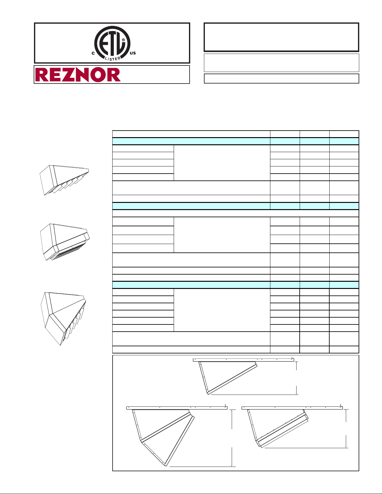
Discharge Air Nozzles,
Options CD57, CD58, and CD59
Installation Form RZ-NA I-LDAP-N (Version A)
®
APPLIES TO: Model LDAP
Nozzles are designed to direct the flow of discharge air from each heat section of a
Reznor Model LDAP downflow heater. Nozzles are available in three configurations:
n Option CD57 - nozzle providing a 25-65° range of air deflection
n Option CD59 - same as CD57 plus 4-way louvers
n Option CD58 - nozzle providing a 50-90° range of air deflection
Model LDAP Size
tion CD57 Pkg P/N
O
Nozzle Section Right Side (1) 207932 (2) 207932 (3) 207932
Nozzle Section Left Sid
Nozzle Section To
Nozzle Section Bottom (1) 207935 (2) 207935 (3) 207935
Nozzle Side Filler (2) 208747 (4) 208747 (6) 208747
Screws, #8-18 x 3/8" long AB point, slotted indented serrated hex
washer head
#8 x 1/2" lon
O
tion CD59 Pkg P/N
Same components as Option CD57 above PLUS
Louver
Top Louver Frame Support
Btm Louver Frame Support
Louver Frame Side
Screws, #8-18 x 3/8" long, AB point, slotted indented serrated hex
washer head
Com
ression Springs (for louvers)
#8 x 1/2" lon
O
tion CD58 Pkg P/N
Nozzle Section Right Side (2) 207932 (4) 207932 (6) 207932
Nozzle Section Left Sid
Nozzle Section To
Nozzle Section Bottom (2) 207935 (4) 207935 (6) 207935
Nozzle Side Filler (4) 208747 (8) 208747 (12) 208747
Nozzle Bottom Filler (1) 208606 (2) 208606 (3) 208606
Screws, #8-18 x 3/8" long AB point, slotted indented serrated hex
washer head
#8 x 1/2" lon
(Read A
NOTE:
nozzle kit(s) as re
TEKS (self-drilling screws)
NOTE:
nozzle kit(s) as re
TEKS (self-drilling screws
NOTE:
nozzle kit(s) as required by the application.
TEKS (self-drilling screws)
NOTE
lication
Package for Size 400 includes parts
for one Option CD57 nozzle; Size 800
includes two nozzles; and Size 1200
includes three nozzles. Select and install
Package for Size 400 includes parts
for one Option CD59 nozzle; Size 800
includes two nozzles; and Size 1200
includes three nozzles. Select and install
for one Option CD58 nozzle; Size 800
includes two nozzles; and Size 1200
includes three nozzles. Select and install
in each Table.)
uired by the application.
uired by the application.
Package for Size 400 includes parts
Obsoletes Form RZ-NA I-LDAP-N
400 800 1200
208094 208886 208887
(1) 207933 (2) 207933 (3) 207933
(1) 207934 (2) 207934 (3) 207934
(20) 195638 (40) 195638 (60) 195638
(6) 195249 (12) 195249 (18) 195249
208100 208890 208891
(7)195578 (14)195578 (21)195578
(1) 207937 (2) 207937 (3) 207937
(1) 208637 (2) 208637 (3) 208637
(2) 207936 (4) 207936 (6) 207936
(18) 195638 (36) 195638 (54) 195638
(7) 195046 (14) 195046 (21) 195046
(12) 195249 (24) 195249 (36) 195249
208097 208888 208889
(2) 207933 (4) 207933 (6) 207933
(2) 207934 (4) 207934 (6) 207934
(46) 195638 (92) 195638
(12) 195249 (24) 195249 (36) 195249
(138)
195638
Nozzle
Dimensions
FIGURE 1 Dimensions
(inches/mm)
Option CD58,
60° Nozzle
Option CD57,
30° Nozzle
24-3/8
(618mm)
14-1/8
(360mm)
16-1/2
(419mm)
Option CD59, 30° Nozzle
with 4-Way Louvers
Form RZ-NA I-LDAP-N, P/N 208899 Rev 3, page 1
Page 2
Installation
WARNING: Improper installation, adjustment, alteration, service, or
maintenance can cause property damage, injury or death. Read the
Instructions
installation, operation, and maintenance instructions thoroughly before
installing or servicing this equipment.
Installation should be done by a qualified agency in accordance with the instructions on this sheet and in compliance with all codes and requirements of authorities having jurisdiction.
n Option CD57 or CD58 ...... Follow instructions in SECTION A.
n Option CD59 .......................Follow instructions in both SECTIONS A and B.
All installations will also include the louvers that were shipped with the heater. Repeat the instructions to install a
nozzle on each heat section.
SECTION A
1. If the heater is installed, turn off the gas and the electric power.
Applies to
n Option CD57
n Option CD58
n Option CD59
FIGURE 3 If installing
Option
CD58,
assemble
the second
nozzle and
attach the
two nozzle
sections.
Nozzle side
fillers attached
in FIGURE 2.
3. If the louvers shipped with the heater have been installed in the heater discharge opening, remove them.
Save the louvers and the springs to be re-installed in the nozzle discharge.
4. Install the Assembled Nozzle in the Heater Outlet (FIGURE 4)
All Options - The discharge opening is square so the nozzle can be installed in any direction. Determine the
appropriate direction and position the assembled nozzle in the heater outlet so that the holes on each side are
lined up with the holes in the heater. Use the 3/8” screws in the kit to attach the nozzle sides to the heater.
Screw ends should be inside the nozzle.
Form RZ-NA I-LDAP-N, P/N 208899 Rev 2, page 2
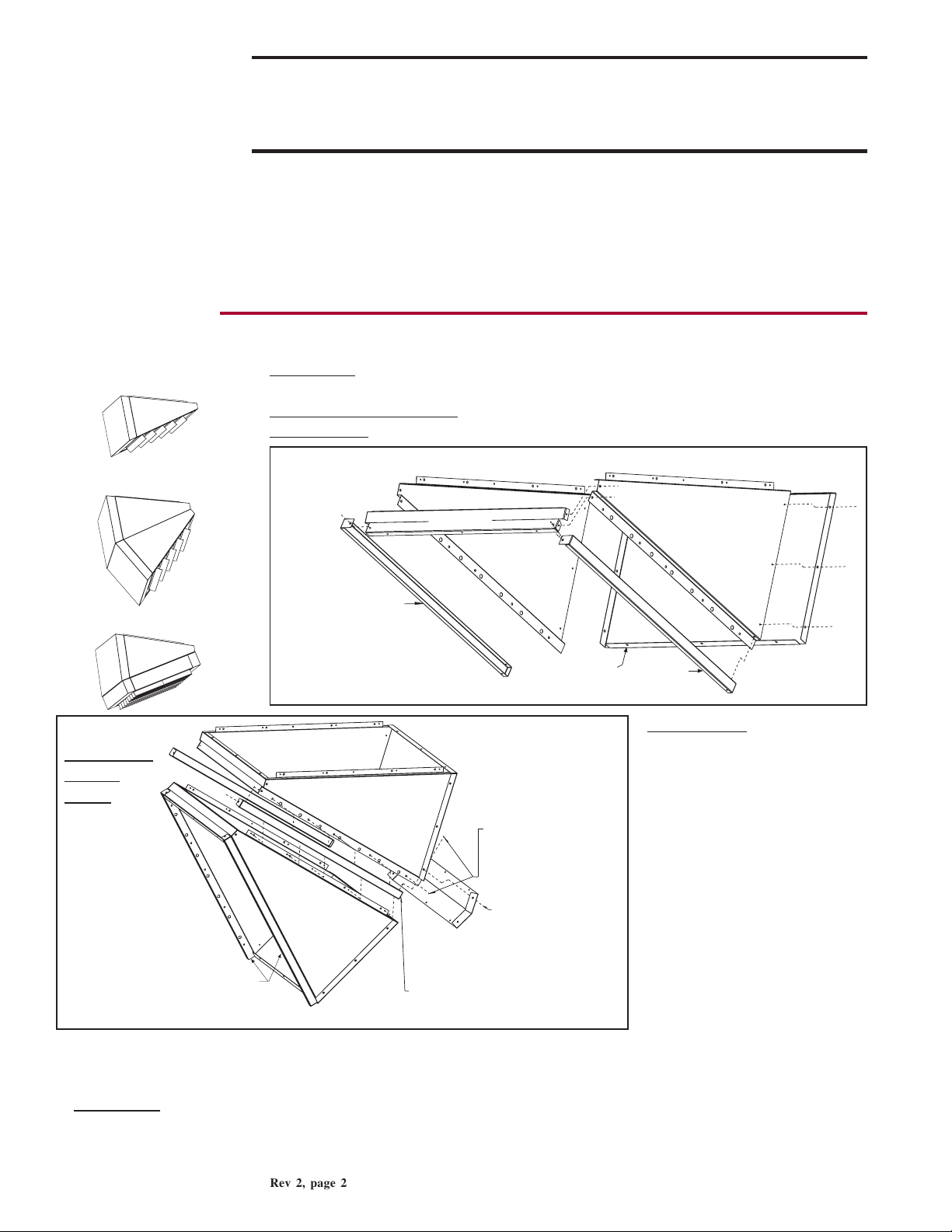
2. Assemble Nozzle
All Options - See FIGURE 2. Assemble a nozzle section. Use the 3/8” screws in
the kit to attach both sides to the top. Attach the bottom to both sides.
Options CD57 and CD58 - Use 3/8” screws to attach side fillers as shown.
Option CD59 - Do not attach side fillers; save to install later.
FIGURE 2 - Assemble a Nozzle Section
Nozzle Top
Nozzle
Side Filler
Use 3/8 screws
(P/N 195638) from the option
package to assemble top, sides,
and bottom. If installing CD57
or CD58, attach side fillers.
CD58 - Second
Nozzle Section
Assembly
CD58 - Nozzle
Section Assembled
in FIGURE 2.
Nozzle Side Fillers - Install these two
side fillers when joining the two
sections of an Option CD58 nozzle.
Nozzle
Right
Side
Nozzle
Bottom
Attach the two
assembled nozzles
and the side fillers
with the 3/8 screws
(P/N 195638).
Nozzle Bottom Filler After nozzle sections
are assembled, remove
appropriate screws and
reuse to attach nozzle
filler as illustrated.
Nozzle
Side Filler
Option CD58 - Assemble the
second nozzle section with-
out attaching the side fillers.
Attach the two nozzles and
the side fillers as shown to
create one nozzle with two
sections (See FIGURE 3).
Position the nozzle bottom
filler over the seam between
the two bottom nozzle sections. Remove the screws that
line up with the holes in the
nozzle bottom filler. Re-insert
the screws securing the filler
over the seam.
Nozzle
Left
Side
Page 3

FIGURE 4 - Fasten
Assembled Nozzle
to Heater Outlet
(NOTE: Option
CD57 is illustrated.
Procedure is the
same for all
options.)
Using the 1/2” self-drilling
screws in the kit, reach
inside the nozzle and
attach the nozzle top and
bottom to the heater outlet.
Use the holes in the nozzle
top and bottom to position
the screws.
(2) Attach nozzle top
and bottom with 1/2
self-drilling screws.
(1) Attach nozzle sides
inside heater outlet
with 3/8 screws.
5. Install the Louvers in the Nozzle Outlet
All Options - Before actually installing the louvers, note the louver curve and determine how the louvers
should be positioned to provide the optimal throw pattern. Louvers may be installed with the curve all the
same direction (either way) or the right half one way and left the other as illustrated in FIGURE 5. Follow
the instructions and refer to the illustration to install the louvers using the compression springs.
Louver Installation Instructions:
a) With the wider section of the louver facing out of the heater, place one of the compression springs over
the tab on the notched end of a louver. The end of the louver with the spring will fit in any direction in
the square opening. How the louver turns depends on which end of the louver is inserted first.
b) Depending on the airflow pattern selected, push the louver tab with the spring into a hole in the discharge
opening and insert the louver tab on the other end into the corresponding hole on the opposite side.
c) Continue installing until all louvers are in place. Adjust the louvers to provide the desired air throw
pattern.
FIGURE 5 - Installing
Airflow direction depends on how the louvers are installed.
Louvers in Nozzle Outlet
Compression Spring
CAUTION: To avoid
getting burned, adjust
louvers while heater is
Airflow direction;
springs are on
the upper end.
Wider side of the
louver blade must
always be facing
out of the heater.
Option CD57 or CD58 - Repeat nozzle installation as required for each heat section. If the heater is installed, turn
on the electric and the gas. Light the heater following the lighting instructions. Check for proper operation.
Option CD59 - Continue to SECTION B.
Airflow direction;
springs are on
the lower end.
not in operation. If
louvers are adjusted
while heater is in
operation, wear
protective gloves.
SECTION B
Applies to
n Option CD59
1. Option CD59 - Assemble the Frame for 4-Way Louvers (See FIGURE 6.)
Using the 3/8” long screws in the kit, attach both sides to the supports.
FIGURE 6 - Assemble the Louver Frame
Bottom Louver Frame
2-3/32 (53mm)
Support (P/N 208637)
(note height of support )
Top Louver Frame
Support (P/N 207937)
(note height of support)
2-31/32 (75mm)
Louver Frame
Side (P/N 207936)
Assemble louver frame with
screws provided (P/N 195638).
Form RZ-NA I-LDAP-N, P/N 208899 Rev 3, page 3
(sides are identical)
Page 4

SECTION B - CD59 Installation Instructions (cont’d)
©2014 Reznor, LLC. All rights reserved. Printed in the U.S.A.
Reznor® is registered in at least the United States.
0514 POD OG Form I-LDAP-N (Version A.2)
2. Install the Assembled Louver Frame in
the Nozzle Outlet (See FIGURE 7.
Note that standard louvers are not
shown but should already be installed
in the nozzle.)
Position the assembled louver frame in
the nozzle outlet so that the holes in the
tabs on each side are lined up with the
holes in the nozzle. The tabs in the louver frame fit between the louvers already
installed in the nozzle discharge. Using
the 3/8” screws (P/N 195638) from the
kit, attach the louver frame tabs to the
nozzle. Screw ends should be inside the
nozzle.
Use the 1/2” self-drilling screws (P/N
195249) to attach the other two sides of
the louver frame. Use the holes in the
louver frame as a template for inserting
the screws.
FIGURE 7 - Option CD59 - Install Louver Frame in
Nozzle Outlet
Nozzle Assembly already
attached to the heater and
with standard louvers (not
shown) in the nozzle outlet
Assembled Louver Frame
(FIGURE 6)
Attach assembled
louver frame to
nozzle assembly
using screws from
the option package.
Attach the two
Nozzle Side
Fillers (saved in
SECTION A,
Step 2.)
FIGURE 8 - Installing
Louvers in the Louver
Frame
Compression Spring
Wider side of the
louver blade must
always be facing
out of the heater.
3. Install the Louvers in the Louver Frame Using the Compression Springs
(See FIGURE 8.)
Before actually installing the louvers, note the louver curve and determine
how the louvers should be positioned to provide the optimal throw pattern.
Depending on the desired direction of airflow, louvers may be installed with
the curve all the same direction (either way) or the right half one way and the
left the other as illustrated in FIGURE 5, page 3.
a) With the wider section facing out of the heater, place one of the compres-
sion springs over the tab on the notched end of the louver.
b) Depending on the throw pattern selected, the end with the spring can go in
either direction. Slide the tab with the spring into one of the holes in either
of the sides. Push the louver, compressing the spring enough to place the
tab on the other end into the corresponding hole in the other side.
c) Continue installing until all louvers are in place.
4. Adjust the louvers to provide the desired throw pattern.
CAUTION: To avoid getting burned, adjust louvers while heater is
not in operation. If louvers are adjusted while heater is in operation,
wear protective gloves.
5. Repeat nozzle installation as required for each heat section. If the heater is in-
stalled, turn on the electric and the gas. Light the heater following the lighting
instructions. Check for proper operation.
Form RZ-NA I-LDAP-N, P/N 208899 Rev 2, page 4
(800) 695-1901; www.RezSpec.com
©2005 Thomas & Betts Corporation, All rights reserved.
MANUFACTURER OF HEATING, COOLING, AND VENTILATING SYSTEMS
Trademark Note: Reznor® is a trademark of Thomas & Betts Corporation
1/05 Form RZ-NA I-LDAP-N (Version A.1)
 Loading...