

Reznor LCSC-3E 30, LCSC-3E 45, LCSC-3E 60, LCSC-3E Series, LCSC-3E 20 Installation, Commissioning, Servicing And User Instructions
...
1801LCSC-3EE--EN
Gas-Fired, Balanced-Flue or Power-Vented Unit Heater
LCSC-3E
20, 30, 45, 60, 75, 100
Installation, commissioning, servicing & user instructions
These appliances meet the following EC Directives
DIR 2009/142/EC : GAD
DIR 2014/30/EC : EMC
DIR 2014/35/EC : LVD
DIR 2006/42/EC : MD
Applies to
Austria, Belarus, Bulgaria, China, Czech Republic, Croatia, Cyprus, Denmark, England, Estonia, Finland,
Germany, Greece, Hungary, Iceland, Latvia, Lithuania, Montenegro, New Zealand, Norway, Poland, Romania,
Russian Federation, Serbia, Slovakia, Slovenia, South Africa, Spain, Sweden, Turkey, Ukraine
WARNING
Improper installation, adjustment, alteration, service, or maintenance can cause property
damage, injury, or death. All work must be carried out by appropriately qualified persons. The
manufacturer does not take any responsibility in the event of non-observance of the regulations
concerning the connection of the apparatus causing a dangerous operation of the apparatus, possibly
resulting in damage to the apparatus and/or environment in which the unit is installed.
Please read this document carefully before commencing installation commissioning and/or servicing.
Leave it with the user or attached to the appliance or gas service meter after installation.
LCSC-3E--EN 1/40
TABLE OF CONTENTS
r
1.0 INTRODUCTION
1.1 Basic Information
1.2 Warranty
2.0 SPECIFICATIONS
2.1 Technical data
2.2 Burner pressure
2.3 Blower curves
2.4 Blower options
2.5 Dimensions
3.0 GENERAL REQUIREMENTS
3.1 Related Documents
3.2 Heater Location
3.3 Combustion Air Inlet Pipe and Flue Pipe
3.4 Air Supply
3.5 Air Distribution System
3.6 Electrical Supply
3.7 Gas Supply
4.0 INSTALLATION
4.1 Uncrating and Preparation
4.2 Suspending the Heater
4.3 Fitting the Combustion Air Inlet/Flue Pipe
System
4.4 Gas Connection
4.5 Electrical Connections
4.6 Room Thermostat Siting
5.0 AIR DISTRIBUTION
6.0 COMMISSIONING AND TESTING
6.1 Electrical Check
6.2 Gas Connection
6.3 Suspension and Support
6.4 Lighting the Heater
6.5 Heater pipe work
6.6 Adjustments
6.6.1 Burner Gas Adjustment
6.7 Air Distribution System
6.8 Heater Controls
6.9 Handing Over
7.0 SERVICING INSTRUCTIONS
7.1 Servicing Procedure
8.0 REMOVAL AND REPLACEMENT OF PARTS
8.1 Main Burner Removal
8.2 Main Burner Injectors
8.3 Ignition System
8.4 Operating Gas Valve
8.5 Limit Controls
8.6 Combustion Air Pressure Switch
8.7 Combustion Air Fan
9.0 FAULT FINDING
10.0 PARTS LIST
11.0 GAS CONVERSION
12.0 USERS INSTRUCTIONS
13.0 HEALTH & SAFETY STATEMENT
HAZARD INTENSITY LEVELS
DANGER Failure to comply will
result in severe
dange
WARNING Failure to comply could
CAUTION Failure to comply
WARNING: The electrical isolator
should only be used in an emergency
and should not be used for closing
down the main burner, as it switches
off the fan prematurely and may
damage the heat exchanger,
invalidating the warranty.
ATTENTION: This appliance is not intended
for use by persons (including children) with
reduced sensory or mental capacities, or lack
of experience and knowledge, unless they have
been given supervision or instruction
concerning use of the appliance by a person
responsible for their safety. Children should be
supervised to ensure that they do not play with
the appliance.
personal injury or
death and/or property
damage.
result in severe
personal injury or
death and/or property
damage
could result in minor
personal injury and/or
property damage.
INTRODUCTION
1
1.1 Basic Information
The instructions in this manual apply to Model
LCSC-3E gas-fired/fan-assisted warm air
heaters. These models have an axial fan for air
delivery. These heaters are designed for
overhead suspension and are suitable for indoor
installation only installed at an operation
ambient temperature between -15°C and 45°C.
When installed as a type C12/C32 and where
LCSC-3E--EN 2/40
the height above floor level is greater than 1.8
meters measured to the underside of the
appliance they may be used as a garage air
heater. This appliance must be installed in
accordance with the rules in force. Before
installation, check that the local distribution
conditions, nature of gas and pressure and
adjustment of the appliance are compatible. A
permanent electricity supply of 230 volts, 50 Hz,

single phase is required.
Heaters are approved for:
Type C12 horizontal vent for balanced-flue
heaters;
Type C32 vertical vent for balanced-flue
heaters;
Type B 22 vertical vent;
When the external control calls for heat, an
electronic control begins the ignition sequence
to provide for a safe start..
About 30 seconds after the call for heat, the fan
will begin circulating warm air. The electronic
control will supervise the flame during the entire
heating cycle to ensure safe operation.
When the required room temperature is
reached, the main burner will shut down leaving
the fan running to cool down the heat
exchanger. After approximately 45 seconds, the
fan delay relay will turn off the fan.
1.2 Warranty: Warranty is void if:
a) LCSC-3E heaters are installed in atmospheres containing flammable vapors or atmospheres
containing chlorinated or halogenated hydrocarbons or atmospheres containing any silicone,
aluminum oxide, etc., that adheres to spark ignition flame sensing probes.
b) The installation is not in accordance with these instructions.
TECHNICAL DATA
2
2.1 Specifications
Table 1a : Technical data
LCSC-3E
20 30 45 60 75 100
Comb. Air & Flue Type B (1)
Comb. Air & Flue Type C (1)
C12, C32, C42, C82
B22P
Connection colars mm 100 100 130 130 130 130
Heat inputs Hs kW 26,42 31,63 54,38 73,25 87,85 114,87
Heat inputs Hi kW 23,80 28,50 49,00 66,00 79,15 103,50
Heat output kW 21,82 25,99 44,64 60,92 73,13 94,50
Thermal efficiency % 91,70 91,20 91,10 92,30 92,39 91,30
Gas consumption G20 m3/h 2,52 3,02 5,19 6,98 8,38 11,19
Gas consumption G31 kg/h 1,86 2,22 3,82 5,15 6,17 8,24
Gas pipe connection (2) inch
½" ¾"
ESP MIN Press Pa 50 50 50 100 150 100
ESP MAX Press Pa 200 300 200 200 350 300
Air flow measured m3/h 2248 2741 4023 5573 7079 8068
Temperature rise (3) K 28 28 32 32 30 34
Electrical service (protection IP20)
230/240V 1N 50Hz 230/240V 1N 50Hz
400V 3P
50Hz
Blower electrical rating W 660 1250 1410 1700 3070 3200
Total electrical rating W 770 1370 1530 1810 3180 3320
Blower Weight kg 14,5 20,5 27 26 41 45
Unit Weight kg 54 55,8 87 99 109 155
Total Weight kg 68,5 76,3 114 125 150 200
(1) Gas appliance Classifications for approved venting methods based on CEN report CR 1749:2001.
(2) There is a difference between the gas connection diameter and the diameter of the supply line. Always use the most
adequate diameter of the supply line to minimize the pressure drop through the gas pipes – if necessary, reduce the
diameter of the supply line at the inlet of the unit.
(3) Figure for isothermal conditions.
LCSC-3E--EN 3/40

Table 1b : Gas categories
Country Gas category Country Gas category
Austria II2H3P Montenegro II2H3+
Belarus II2H3+ New Zealand II2H3+
Bulgaria I2H or I3P Norway II2H3 B/P
China II2H3+ Poland II2E3P
Czech republic II2H3+ Portugal II2H3+
Croatia II2H3P Romania II2H3 B/P
Cyprus II2H3+ Russian Federation I2H or I3P
Denmark II2H3 B/P Serbia II2H3+
England II2H3+ Slovakia II2H3+
Estonia II2H3+ Slovenia II2H3+
Finland II2H3 B/P South Africa II2H3+
Germany I2ELL Spain II2H3+
Greece II2H3+ Sweden II2H3 B/P
Hungary II2HS3P Turkey II2H3+
Iceland II2H3+ Ukraine I2H or I3P
Latvia II2H3+
Lithuania II2H3+
2.2 Burner pressure & injector size
Table 2:
Belarus, China, Croatia, Czech Republic, Cyprus, England, Estonia, Greece, Iceland, Latvia, Lithuania,
Montenegro, New Zealand, Portugal, Serbia, Slovenia, Slovakia, South Africa, Spain , Turkey, Poland
LCSC-3E
Special Poland
LCSC-3E
Burner pressures & injector sizes
Injector quantity 5 6 10 8 10 12
Injector size
G20
Nat. Gas
Prop. Gas
Burner pressure (1) mbar 8,00 7,25 6,90 8,50 8,30 7,50
Inlet pressure mbar
Injector quantity
Injector size
G31
Burner pressure (1) mbar
Inlet pressure mbar
Injector quantity
Injector size
G27
Burner pressure (1) mbar
Inlet pressure mbar
Injector quantity
Injector size
G2,350
Burner pressure (1) mbar
Inlet pressure mbar
(1) with open service door
Model2030 456075100
mm 2,10 2,10 2,20 2,70 2,70 2,90
marking 210 210 220 270 270 290
20
561081012
mm
marking
Model2030 456075100
mm
marking
mm
marking
1,15 1,15 1,15 1,50 1,45 1,50
115 115 115 150 145 150
34,20 34,40 35,90 35,20 35,40 34,40
37
5610-10-
2,40 2,40 2,40 - 3,00 -
240 240 240 - 300 -
8,30 8,20 8,25 - 9,25 -
20
5610-10-
2,60 2,60
260 260
8,25 8,45
2,60
260
8,40
13
-
-
-
3,90
390
5,25
-
-
-
LCSC-3E--EN 4/40

Austria, Germany, Hungary, Russian Federation, Ukraine
LCSC-3E
Injector quantity
Injector size
G20
Nat. Gas
Prop. Gas
Bulgaria, Denmark, Finland, Norway, Sweden
LCSC-3E
Nat. Gas
Prop. Gas
Burner pressure (1) mbar 8,00 7,25 6,90 8,50 8,30 7,50
Inlet pressure mbar
Injector quantity
Injector size
G31
Burner pressure (1) mbar
Inlet pressure mbar
(* ): Inlet pressure for Hungary = 25mbar
(**): no nat gas for Germany
Injector quantity 5 6 10 8 10 12
Injector size
G20
Burner pressure (1) mbar 8,00 7,25 6,90 8,50 8,30 7,50
Inlet pressure mbar
Injector quantity
Injector size
G31
Burner pressure (1) mbar
Inlet pressure mbar
Model2030 456075100
561081012
mm 2,10 2,10 2,20 2,70 2,70 2,90
marking 210 210 220 270 270 290
561081012
mm
marking
Model2030 456075100
mm 2,10 2,10 2,20 2,70 2,70 2,90
marking 210 210 220 270 270 290
mm
marking
1,15 1,15 1,15 1,50 1,45 1,50
115 115 115 150 145 150
34,20 34,40 35,90 35,20 35,40 34,40
561081012
1,15 1,15 1,15 1,50 1,45 1,50
115 115 115 150 145 150
34,20 34,40 35,90 35,20 35,40 34,40
20(*)
50
20
30
Romania
LCSC-3E
Injector quantity 5 6 10 8 10 12
Injector size
G20
Nat. Gas
Prop. Gas
(1) : with open service door
Burner pressure (1) mbar 8,00 7,25 6,90 8,50 8,30 7,50
Inlet pressure mbar
Injector quantity
Injector size
G31
Burner pressure (1) mbar
Inlet pressure mbar
Model2030 456075100
mm 2,10 2,10 2,20 2,70 2,70 2,90
marking 210 210 220 270 270 290
20
561081012
mm
marking
1,15 1,15 1,15 1,50 1,45 1,50
115 115 115 150 145 150
34,20 34,40 35,90 35,20 35,40 34,40
30
LCSC-3E--EN 5/40

2.3 Blower curves LCSC-3E
LCSC-3E--EN 6/40

LCSC-3E--EN 7/40

LCSC-3E--EN 8/40

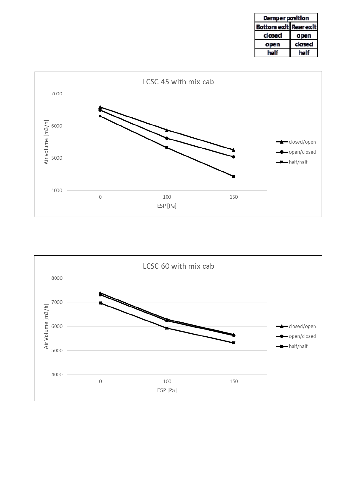
2.4 Blower options LCSC-3E
2.4.1 Mixing cabinet LCSC-3E
Damperposition
Bottomexit Rearexit
closed open
open closed
half half
LCSC-3E--EN 9/40
LCSC-3E--EN 10/40

LCSC-3E--EN 11/40
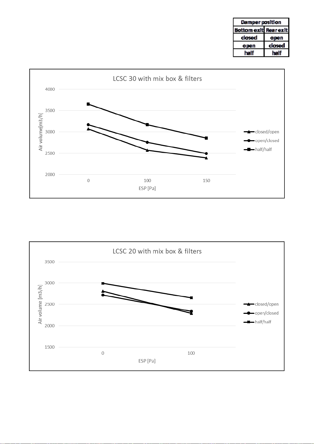
2.4.2 Mixing cabinet and filters LCSC-3E
LCSC-3E--EN 12/40
 Loading...