

Reznor LCSC-3E 30, LCSC-3E 45, LCSC-3E 60, LCSC-3E, LCSC-3E 20 Installation, Commissioning, Servicing And User Instructions
...Page 1

1801LCSC-3EE--EN
Gas-Fired, Balanced-Flue or Power-Vented Unit Heater
LCSC-3E
20, 30, 45, 60, 75, 100
Installation, commissioning, servicing & user instructions
These appliances meet the following EC Directives
DIR 2009/142/EC : GAD
DIR 2014/30/EC : EMC
DIR 2014/35/EC : LVD
DIR 2006/42/EC : MD
Applies to
Austria, Belarus, Bulgaria, China, Czech Republic, Croatia, Cyprus, Denmark, England, Estonia, Finland,
Germany, Greece, Hungary, Iceland, Latvia, Lithuania, Montenegro, New Zealand, Norway, Poland, Romania,
Russian Federation, Serbia, Slovakia, Slovenia, South Africa, Spain, Sweden, Turkey, Ukraine
WARNING
Improper installation, adjustment, alteration, service, or maintenance can cause property
damage, injury, or death. All work must be carried out by appropriately qualified persons. The
manufacturer does not take any responsibility in the event of non-observance of the regulations
concerning the connection of the apparatus causing a dangerous operation of the apparatus, possibly
resulting in damage to the apparatus and/or environment in which the unit is installed.
Please read this document carefully before commencing installation commissioning and/or servicing.
Leave it with the user or attached to the appliance or gas service meter after installation.
LCSC-3E--EN 1/40
Page 2
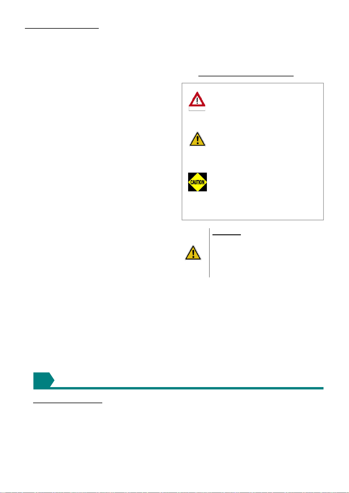
TABLE OF CONTENTS
r
1.0 INTRODUCTION
1.1 Basic Information
1.2 Warranty
2.0 SPECIFICATIONS
2.1 Technical data
2.2 Burner pressure
2.3 Blower curves
2.4 Blower options
2.5 Dimensions
3.0 GENERAL REQUIREMENTS
3.1 Related Documents
3.2 Heater Location
3.3 Combustion Air Inlet Pipe and Flue Pipe
3.4 Air Supply
3.5 Air Distribution System
3.6 Electrical Supply
3.7 Gas Supply
4.0 INSTALLATION
4.1 Uncrating and Preparation
4.2 Suspending the Heater
4.3 Fitting the Combustion Air Inlet/Flue Pipe
System
4.4 Gas Connection
4.5 Electrical Connections
4.6 Room Thermostat Siting
5.0 AIR DISTRIBUTION
6.0 COMMISSIONING AND TESTING
6.1 Electrical Check
6.2 Gas Connection
6.3 Suspension and Support
6.4 Lighting the Heater
6.5 Heater pipe work
6.6 Adjustments
6.6.1 Burner Gas Adjustment
6.7 Air Distribution System
6.8 Heater Controls
6.9 Handing Over
7.0 SERVICING INSTRUCTIONS
7.1 Servicing Procedure
8.0 REMOVAL AND REPLACEMENT OF PARTS
8.1 Main Burner Removal
8.2 Main Burner Injectors
8.3 Ignition System
8.4 Operating Gas Valve
8.5 Limit Controls
8.6 Combustion Air Pressure Switch
8.7 Combustion Air Fan
9.0 FAULT FINDING
10.0 PARTS LIST
11.0 GAS CONVERSION
12.0 USERS INSTRUCTIONS
13.0 HEALTH & SAFETY STATEMENT
HAZARD INTENSITY LEVELS
DANGER Failure to comply will
result in severe
dange
WARNING Failure to comply could
CAUTION Failure to comply
WARNING: The electrical isolator
should only be used in an emergency
and should not be used for closing
down the main burner, as it switches
off the fan prematurely and may
damage the heat exchanger,
invalidating the warranty.
ATTENTION: This appliance is not intended
for use by persons (including children) with
reduced sensory or mental capacities, or lack
of experience and knowledge, unless they have
been given supervision or instruction
concerning use of the appliance by a person
responsible for their safety. Children should be
supervised to ensure that they do not play with
the appliance.
personal injury or
death and/or property
damage.
result in severe
personal injury or
death and/or property
damage
could result in minor
personal injury and/or
property damage.
INTRODUCTION
1
1.1 Basic Information
The instructions in this manual apply to Model
LCSC-3E gas-fired/fan-assisted warm air
heaters. These models have an axial fan for air
delivery. These heaters are designed for
overhead suspension and are suitable for indoor
installation only installed at an operation
ambient temperature between -15°C and 45°C.
When installed as a type C12/C32 and where
LCSC-3E--EN 2/40
the height above floor level is greater than 1.8
meters measured to the underside of the
appliance they may be used as a garage air
heater. This appliance must be installed in
accordance with the rules in force. Before
installation, check that the local distribution
conditions, nature of gas and pressure and
adjustment of the appliance are compatible. A
permanent electricity supply of 230 volts, 50 Hz,
Page 3

single phase is required.
Heaters are approved for:
Type C12 horizontal vent for balanced-flue
heaters;
Type C32 vertical vent for balanced-flue
heaters;
Type B 22 vertical vent;
When the external control calls for heat, an
electronic control begins the ignition sequence
to provide for a safe start..
About 30 seconds after the call for heat, the fan
will begin circulating warm air. The electronic
control will supervise the flame during the entire
heating cycle to ensure safe operation.
When the required room temperature is
reached, the main burner will shut down leaving
the fan running to cool down the heat
exchanger. After approximately 45 seconds, the
fan delay relay will turn off the fan.
1.2 Warranty: Warranty is void if:
a) LCSC-3E heaters are installed in atmospheres containing flammable vapors or atmospheres
containing chlorinated or halogenated hydrocarbons or atmospheres containing any silicone,
aluminum oxide, etc., that adheres to spark ignition flame sensing probes.
b) The installation is not in accordance with these instructions.
TECHNICAL DATA
2
2.1 Specifications
Table 1a : Technical data
LCSC-3E
20 30 45 60 75 100
Comb. Air & Flue Type B (1)
Comb. Air & Flue Type C (1)
C12, C32, C42, C82
B22P
Connection colars mm 100 100 130 130 130 130
Heat inputs Hs kW 26,42 31,63 54,38 73,25 87,85 114,87
Heat inputs Hi kW 23,80 28,50 49,00 66,00 79,15 103,50
Heat output kW 21,82 25,99 44,64 60,92 73,13 94,50
Thermal efficiency % 91,70 91,20 91,10 92,30 92,39 91,30
Gas consumption G20 m3/h 2,52 3,02 5,19 6,98 8,38 11,19
Gas consumption G31 kg/h 1,86 2,22 3,82 5,15 6,17 8,24
Gas pipe connection (2) inch
½" ¾"
ESP MIN Press Pa 50 50 50 100 150 100
ESP MAX Press Pa 200 300 200 200 350 300
Air flow measured m3/h 2248 2741 4023 5573 7079 8068
Temperature rise (3) K 28 28 32 32 30 34
Electrical service (protection IP20)
230/240V 1N 50Hz 230/240V 1N 50Hz
400V 3P
50Hz
Blower electrical rating W 660 1250 1410 1700 3070 3200
Total electrical rating W 770 1370 1530 1810 3180 3320
Blower Weight kg 14,5 20,5 27 26 41 45
Unit Weight kg 54 55,8 87 99 109 155
Total Weight kg 68,5 76,3 114 125 150 200
(1) Gas appliance Classifications for approved venting methods based on CEN report CR 1749:2001.
(2) There is a difference between the gas connection diameter and the diameter of the supply line. Always use the most
adequate diameter of the supply line to minimize the pressure drop through the gas pipes – if necessary, reduce the
diameter of the supply line at the inlet of the unit.
(3) Figure for isothermal conditions.
LCSC-3E--EN 3/40
Page 4

Table 1b : Gas categories
Country Gas category Country Gas category
Austria II2H3P Montenegro II2H3+
Belarus II2H3+ New Zealand II2H3+
Bulgaria I2H or I3P Norway II2H3 B/P
China II2H3+ Poland II2E3P
Czech republic II2H3+ Portugal II2H3+
Croatia II2H3P Romania II2H3 B/P
Cyprus II2H3+ Russian Federation I2H or I3P
Denmark II2H3 B/P Serbia II2H3+
England II2H3+ Slovakia II2H3+
Estonia II2H3+ Slovenia II2H3+
Finland II2H3 B/P South Africa II2H3+
Germany I2ELL Spain II2H3+
Greece II2H3+ Sweden II2H3 B/P
Hungary II2HS3P Turkey II2H3+
Iceland II2H3+ Ukraine I2H or I3P
Latvia II2H3+
Lithuania II2H3+
2.2 Burner pressure & injector size
Table 2:
Belarus, China, Croatia, Czech Republic, Cyprus, England, Estonia, Greece, Iceland, Latvia, Lithuania,
Montenegro, New Zealand, Portugal, Serbia, Slovenia, Slovakia, South Africa, Spain , Turkey, Poland
LCSC-3E
Special Poland
LCSC-3E
Burner pressures & injector sizes
Injector quantity 5 6 10 8 10 12
Injector size
G20
Nat. Gas
Prop. Gas
Burner pressure (1) mbar 8,00 7,25 6,90 8,50 8,30 7,50
Inlet pressure mbar
Injector quantity
Injector size
G31
Burner pressure (1) mbar
Inlet pressure mbar
Injector quantity
Injector size
G27
Burner pressure (1) mbar
Inlet pressure mbar
Injector quantity
Injector size
G2,350
Burner pressure (1) mbar
Inlet pressure mbar
(1) with open service door
Model2030 456075100
mm 2,10 2,10 2,20 2,70 2,70 2,90
marking 210 210 220 270 270 290
20
561081012
mm
marking
Model2030 456075100
mm
marking
mm
marking
1,15 1,15 1,15 1,50 1,45 1,50
115 115 115 150 145 150
34,20 34,40 35,90 35,20 35,40 34,40
37
5610-10-
2,40 2,40 2,40 - 3,00 -
240 240 240 - 300 -
8,30 8,20 8,25 - 9,25 -
20
5610-10-
2,60 2,60
260 260
8,25 8,45
2,60
260
8,40
13
-
-
-
3,90
390
5,25
-
-
-
LCSC-3E--EN 4/40
Page 5

Austria, Germany, Hungary, Russian Federation, Ukraine
LCSC-3E
Injector quantity
Injector size
G20
Nat. Gas
Prop. Gas
Bulgaria, Denmark, Finland, Norway, Sweden
LCSC-3E
Nat. Gas
Prop. Gas
Burner pressure (1) mbar 8,00 7,25 6,90 8,50 8,30 7,50
Inlet pressure mbar
Injector quantity
Injector size
G31
Burner pressure (1) mbar
Inlet pressure mbar
(* ): Inlet pressure for Hungary = 25mbar
(**): no nat gas for Germany
Injector quantity 5 6 10 8 10 12
Injector size
G20
Burner pressure (1) mbar 8,00 7,25 6,90 8,50 8,30 7,50
Inlet pressure mbar
Injector quantity
Injector size
G31
Burner pressure (1) mbar
Inlet pressure mbar
Model2030 456075100
561081012
mm 2,10 2,10 2,20 2,70 2,70 2,90
marking 210 210 220 270 270 290
561081012
mm
marking
Model2030 456075100
mm 2,10 2,10 2,20 2,70 2,70 2,90
marking 210 210 220 270 270 290
mm
marking
1,15 1,15 1,15 1,50 1,45 1,50
115 115 115 150 145 150
34,20 34,40 35,90 35,20 35,40 34,40
561081012
1,15 1,15 1,15 1,50 1,45 1,50
115 115 115 150 145 150
34,20 34,40 35,90 35,20 35,40 34,40
20(*)
50
20
30
Romania
LCSC-3E
Injector quantity 5 6 10 8 10 12
Injector size
G20
Nat. Gas
Prop. Gas
(1) : with open service door
Burner pressure (1) mbar 8,00 7,25 6,90 8,50 8,30 7,50
Inlet pressure mbar
Injector quantity
Injector size
G31
Burner pressure (1) mbar
Inlet pressure mbar
Model2030 456075100
mm 2,10 2,10 2,20 2,70 2,70 2,90
marking 210 210 220 270 270 290
20
561081012
mm
marking
1,15 1,15 1,15 1,50 1,45 1,50
115 115 115 150 145 150
34,20 34,40 35,90 35,20 35,40 34,40
30
LCSC-3E--EN 5/40
Page 6

2.3 Blower curves LCSC-3E
LCSC-3E--EN 6/40
Page 7

LCSC-3E--EN 7/40
Page 8

LCSC-3E--EN 8/40
Page 9

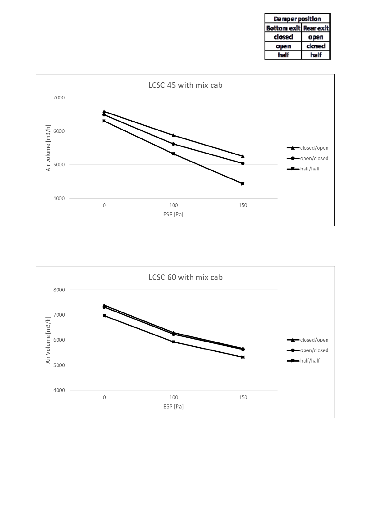
2.4 Blower options LCSC-3E
2.4.1 Mixing cabinet LCSC-3E
Damperposition
Bottomexit Rearexit
closed open
open closed
half half
LCSC-3E--EN 9/40
Page 10
LCSC-3E--EN 10/40
Page 11

LCSC-3E--EN 11/40
Page 12
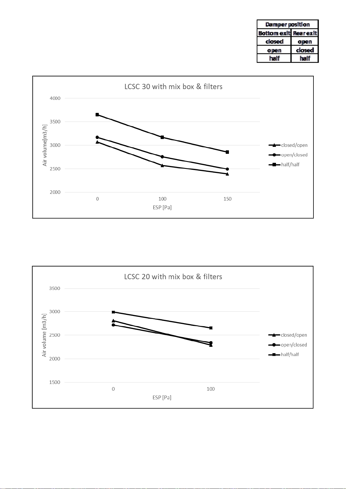
2.4.2 Mixing cabinet and filters LCSC-3E
LCSC-3E--EN 12/40
Page 13

LCSC-3E--EN 13/40
Page 14

LCSC-3E--EN 14/40
Page 15

2.4.3 Free blowing
Freeblowing Dimensions[mm]
LCSC‐3E Restriction
partno
20 ‐ ‐‐‐
30 1002436 58 70 240
45 1002437 154 154 320
60 1002438 130 154 320
75 1002439 130 154 396
100 1002440 166 178 396
A B C
LCSC-3E--EN 15/40
Page 16

2.5 Dimensions standard unit
LCSC-3E--EN 16/40
Page 17

Dimensions unit with mixing cabinet (option 526)
LCSC-3E--EN 17/40
Page 18

GENERAL REQUIREMENTS
d
3
3.1 Related documents
It is important that all gas appliances are
installed in accordance with the rules in force
and by appropriately qualified persons.
Failure to install appliances correctly could
lead to prosecution. It is in your own interest
and that of safety to ensure compliance with
the law.
3.2 Heater location
The location chosen for the air heater must
permit the provision of a satisfactory flue
system venting to outdoor atmosphere and
adequately ventilated to provide for
combustion air. The location must also
provide sufficient space to allow the heater to
be serviced.
Table 3
Minimum installation clearances (mm)
LCSC-3E 100
Top 150
Flue connector 150
Access panel 500
Non access si
Bottom 150
Rear* 250
* Measure rear clearance from the back of the blower
Table 4
Recommended mounting heights to underside
(m) (*)
LCSC-3E 20
Mounting height 3 4 5
* Height from floor to bottom surface of heater. These
are recommendations only. Positioning of heaters
depends on application.
150
3045
others
Where air heaters are located in the center of
the space to be heated, the air should be
discharged toward outside walls. In large
areas, they should be located to discharge
air along outside walls with additional
heaters provided to blow air into the center of
the area.
In places where infiltration of cold is
excessive, such as entrance doors it is
desirable to locate a heater so that warm air
is discharged directly toward the source of
cold air from a distance of 4,5 - 6,0m
Air heaters should not be installed in
corrosive atmospheres, i.e. near
plating or degreasing plants or in
areas where there is a fire risk.
Do not locate the air heater where it
may be exposed to water spray, rain,
etc.
3.3 Combustion air supply & flue
system
The air heater may be installed as a
balanced flue (Type C) heater requiring both
a combustion air inlet duct and a flue pipe or
as a power vented (Type B) heater, which
requires only a flue pipe exhausting to
outdoors. All products of combustion must be
flued to outdoor atmosphere.
Figure 2a: Combustion air and flue pipe sockets
Air heaters should, where ever possible
always be installed to blow toward or along
external wall surfaces. Where two or more air
heaters are installed in the same room, a
general scheme to ensure continuous air
circulation should be maintained for best
results. Suspended heaters are most
effective when located as close to the
occupancy zone as possible, this fact should
be born in mind when determining the
mounting heights to be used. Care should be
exercised to avoid directing warm air directly
onto the occupants. Partitions, columns,
counters, storage racking, etc. should be
taken into account when choosing the
location so that an unobstructed path for the
Legend :
1 Flue outlet socket
2 Combustion air inlet opening
3 Gas connection inlet with sealing ring
4 Electrical connections
air circulation can be maintained.
LCSC-3E--EN 18/40
Page 19

Each heater installed as a type B appliance
must be fitted with an individual flue pipe and
the combustion air inlet opening must be
provided with a protection grill (ask your
distributor for the appropriate protection grill
(IP20) (dia130 = PN 02 25094 ). Each
heater installed as a type C appliance must
be fitted with an individual combustion
air/flue pipe system. Only systems specified
by the air heater manufacturer may be used.
Common flue and combustion air systems
must not be used
IMPORTANT: The flue must be installed in
accordance with national and local regulations.
Failure to provide proper flueing could result in
death, serious injury and/or property damage.
The air heater must be installed with a flue to
the outside of the building. Safe operation of
any power vented gas apparatus requires a
properly operating flue system, correct
provision for combustion air, and regular
maintenance and inspection.
3.3.1 Flues for power vented installations
(Type B appliances)
If the air heater is to be installed as a type B
appliance, air for combustion will be taken
from within the space where the heater is
installed. Ensure that an adequate air supply
for combustion and ventilation is provided
within the building in accordance with the
regulations & rules in force.
Table 5 shows flue pipe sizes and maximum
pipe lengths. The minimum flue length is 0.5
meters.
Table 5 Flue pipe diameters & maximum
lengths
LCSC-3E other sizes
Heater socket & mm
pipe dia
Maximum straight m
length
Equivalent length m
of 45° elbow
Equivalent length m
of 90° elbow
20 & 30
100
130
9
0.75
1.5
Single wall flue pipes are required. All joints
must be sealed to prevent products of
combustion from leaking into the building. An
approved flue terminal is required.
If the flue passes through a combustible
element of the building it must be enclosed
by a sleeve of non-combustible material and
separated from the sleeve by at least a 25
mm air break.
The temperature of any combustible material
near to the flue must not exceed 65°C when
the heater is in operation. The flue must be
at least 50 mm away from any combustible
material.
Single wall flue pipe exposed to cold air or
run through unheated areas must be
insulated. Where condensation is
unavoidable, provision must be made for the
condensation to flow freely to a point to
which it can be released, i.e. a drain or gully.
The condensation drain from the flue must be
constructed from non-corrodible material not
less than 20 mm diameter. Copper or copper
based alloys must not be used for
condensation drains.
3.3.2 Combustion air inlet pipe & flue pipe for
balanced flue installation (Type C appliances)
Balanced flue air heaters are designed to be
fitted with a combustion air inlet pipe that
obtains outdoor air and a flue pipe that
exhausts flue products to outdoors.
Air heaters if fitted with a power venter
permitting either a vertical or horizontal
combustion air inlet/flue pipe system. The
heaters must be installed with a
concentric vertical or horizontal
flue/combustion air inlet. The heaters are
only approved for use when installed with
the appropriate approved concentric vent
terminal. See table 6.
Both the flue and combustion air pipes must be
sealed. Use gasket sealed seamless aluminum
pipe or equivalent.
The flue pipe must include a re-sealable test
port to allow good average sampling of the flue
gas mixture for testing, the port must be at
least 450 mm away from the air heater flue
connection socket.
Follow any flue pipe manufacturers’ installation
instructions for making joints, including
connections to the air heater, for passing
through a building element and for support
requirements. If more than one air heater is
being installed in the same place each heater
must have a separate flue system.
Where condensation is unavoidable,
provision must be made for the condensation
to flow freely to a point to which it can be
released, i.e. a drain or gully. The
condensation drain from the flue must be
constructed from non-corrodible material not
less than 20 mm diameter. Copper or copper
based alloys must not be used for
condensation drains.
LCSC-3E--EN 19/40
Page 20

Figure 2b :
Combustion air and flue pipe sockets, Type C
1 Flue pipe outlet collar
2 Combustion air pipe inlet collar
Table 6
Combustion air inlet & flue pipe requirements
LCSC‐3E
Heatersocket&pipedia
1
2
20‐30 Othersizes
mm Fluepipe/Inletpipe 100 130
Maxstraightlength
Equivalentlengthof45°
elbow
Equivalentlengthof90°
elbow
90°elbow
mFluepipe/Inletpipe 9 9
mFluepipe/Inletpipe 0,75 0,75
mFluepipe/Inletpipe 1,5 1,5
mFluepipe/Inletpipe 1,5 1,5EquivalentLengthof
LCSC-3E--EN 20/40
Page 21

3.4 Air supply
Figure 2c: Combustion air and flue pipe sockets, Type B
It is important to ensure that
there is an adequate air supply
at all times for both
combustion and heating
requirements. Modern
constructions involve the
greater use of insulation,
improved vapor barriers, and
weather proofing. This practice
means that buildings are
sealed much tighter than in the
past.
1 Flue pipe outlet collar
2 combustion air inlet opening
The combustion air supply for a power vented
gas fired air heater (Type B installation) can
be affected by lack of air supply. Natural
infiltration may not be adequate. Use of extract
fans aggravates this situation. It is important
to ensure that there is an adequate air supply
at all times. Reliance on doors and windows is
not allowed. Always ensure that an adequate
inlet for fresh air for combustion is provided
sized to suit the total installation of any
combustion apparatus.
Fit an access guard to the combustion air inlet
on the back of the heater and take appropriate
action to ensure that it remains unblocked.
See figure 2c.
WARNING: This model air heater is
installed as a type B application and is
designed to take air for combustion
from the space in which it is installed.
Do not restrict the combustion air
intake.
3.5 Air distribution
Follow recommended practice for building air
distribution.
The following notes are of particular
importance:
"Where free blowing air heaters are installed it
must be taken into account that heated air is
buoyant when it leaves the appliance, therefore, air
patterns within the space being heated will modify
the air throw pattern achieved.
having low heat loss where single heaters are required to
cover a large floor area and in buildings with high ceiling
heights, air re-circulation fans e.g. Maximizors may be
fitted to ensure even heat distribution and minimize
stratification. Care should be taken to avoid impeding air
flow with storage racking, partitions, etc."
In building
3.6 Electrical supply
Wiring external to the air heater must be
carried out in accordance with the rules if
force and by appropriately qualified persons.
A constant 230 Volt 50 Hertz single phase
fused electricity supply with neutral link is
required. All heaters and controls must be
earthed. A lockable isolator with contact
separation of at least 3.0 mm on all poles
should be installed adjacent to the appliance
and within reach of any person working on the
heater.
When a number of heaters are to be
connected as part of a single installation each
heater must be provided with a separate
isolator.
The electrical connection to the air heater is at
the back of the appliance. The final connection
must be made in the terminals provided in the
control compartment.
Follow the wiring diagram provided with the air
heater.
Electrical supply cable conductor size should
be 1.5 mm. Fit the cord grip supplied with the
heater. The length of conductors between the
cord grip and the terminals must be such that
in the event that the cable becomes taut the
line conductors do so before the earth
conductor.
3.7 Gas supply
LCSC-3E air heaters are designed to operate
on either natural gas (G20) or propane gas
(G31). Refer to the specifications in section 2
of this document and to the data plate for
details of supply pressures.
The gas meter and gas service must be
checked by the supply undertaking to ensure
that they are adequate to deal with the total
1
2
LCSC-3E--EN 21/40
Page 22

load of all gas fired apparatus installed.
INSTALLATION
4
4.1 Unpacking and preparation
Prior to dispatch, the air heater was operated
and tested at the factory. If the heater has
incurred any damage in shipment, file a
report claim within 2 working days from
receipt. Check the shipping label and data
plate to ensure the specification of gas and
electrical supplies are compatible. Read this
document and become familiar with the
installation requirements and the appliance
before commencing installation.
4.2 Suspending the air heater
Before installing the appliance, check to
ensure that the supporting structure is
adequate to carry the weight of the appliance
and its ancillaries i.e. flue system. Please
check weighs specified in table 1
When the heater is lifted for suspension,
support the bottom of the heater with
plywood or other appropriately placed
material. If the bottom is not supported,
damage could occur.The heater is supplied
with four point suspension. All points must be
used. Two threaded nut retainers are
provided on each side of the top of the
heater. See dimensions in section 2.2 and
figure 3.Be sure that the threaded hanger
rods are locked to the heater as illustrated in
figure 3. Recommended maximum hanger
rod length is 1.8m.
Figure 3 Suspension detail
4.3 Fitting the Combustion air inlet/Flue
system
Flue pipe runs may be horizontal or vertical
and terminate either through the wall or roof.
See table 5 for maximum pipe length for an
appliance installed as type B or table 6 for
maximum lengths and approved supplied
concentric terminals for a heater installed as
a type C appliance. All pipe runs must be
independently supported so that the heater
does not carry any of the weight of the flue
system.
4.3.1 Fitting the flue pipe
The flue pipe socket is located on the back of
the air heater. Flue pipes must be sealed.
Use seamless, aluminum pipe or equivalent.
Follow pipe manufacturer's instructions (see
figures 4 & 5).
Table 7 Flue pipe socket size (dia mm)
LCSC-3E 20 & 30 other sizes
Socket 100 130
4.3.2 Installing a guard on the combustion air
inlet pipe for power vent (Type B installations)
The combustion air inlet socket is located at
the back of the heater. When installed as a
type B appliance, protect the inlet by fitting
an access guard on the socket. Do not block
this socket as it supplies combustion air for
the burner (see figure 4).
Figure 4
Add a nut to lock the M10x1.5
hanger rod to the heater
4.3.3 Fitting the combustion air inlet pipe for
balanced flue (Type C installations)
The combustion air pipe attaches directly to
IMPORTANT: Suspend the heater from the
threaded nut retainers. Do not suspend from the
heater cabinet panels. Do not place or add
additional weight to the suspended air heater.
See hazard levels, page 2.The heater must be
installed in a level plane to ensure proper
operation.
LCSC-3E--EN 22/40
the inlet socket at the back of the heater. Air
inlet pipes must be sealed. Use seamless
aluminum or equivalent. Follow the pipe
manufacturer's installation instructions. See
typical installations in figure 5.
Table 8 Air inlet socket size (dia mm)
LCSC-3E 20 & 30 other sizes
Socket 100 130
Page 23

Figure 5
4.4 Gas connection
Connection to a gas network may only be
carried out by appropriately qualified
persons. The gas installation must comply
with the rules in force using materials
appropriate for gas installation.
To facilitate servicing, the air heater must be
fitted with an approved gas service tap and
union fitting or union tap adjacent to the
appliance. The inlet gas supply line must be
installed so as to permit the access door to
be opened and to allow removal of the slide
out burner assembly.
Air heaters suspended by flexible suspension
materials or drop rods must be connected to
the gas supply using an approved flexible
connector. Sufficient slack must be provided
in the connection to allow for movement of
the appliance. Use a flexible connector of
suitable size to reduce the pressure drop and
the possibility of gas flow noise.
Do not use the appliance gas supply
to balance or support any part of the
appliance.
Figure 6
1 Gas tube inlet sealing ring
2 Inlet gas pipe
3 Union fitting
4 Gas service tap
5 Gas pipe : Sizes 20 & 30 :
Other sizes
½”
: ¾”
4.5 Electrical connections
The electrical installation may only be carried
out by appropriately qualified persons
observing the rules in force.
All electrical connections should be made in
the heater control compartment (refer to
figure 9). Screw type terminals are provided.
Connections should be in accordance with
the terminal markings and the wiring diagram
affixed to the air heater or included with this
document.
THIS APPLIANCE MUST BE
EARTHED!
danger
The minimum external controls required for
the air heater are a room thermostat. It is
essential the main input line and neutral to
terminals L and N remains live at all times
even when the appliance is switched off this
is to ensure correct operation of the unit.
An indicator light and burner reset button are
fitted inside the appliance. To add a remote
reset button, make connections to the
terminals in the electric box as indicated on
the wiring diagram.
IMPORTANT: If the reset button requires
activating for any reason the cause should be
identified before resetting. After resetting stay
with the appliance for long enough to ensure
that lock-out does not reoccur (suggest 5
minutes).Fix all electric cables and installer’s
wiring to the control panel and ensure they do
not touch the combustion collector box.
4.6 Room thermostat location
Do not attempt to control more than 1 air
heater from a room thermostat or control
panel unless a properly wired relay is fitted.
Follow instructions supplied with such
panels.
The location of the room thermostat is
important. It should not be fitted on an
outside wall. Avoid location in draughty areas
or where it may be influenced by heat
sources e.g. the sun, process plant, etc. The
thermostat or temperature sensor should be
mounted on a vibration free surface and
mounted about 1,5 meters above floor level.
Follow the thermostat manufacturers fitting
instructions. The thermostat must be suitable
for switching 230 volts.
LCSC-3E--EN 23/40
Page 24

AIR DISTRIBUTION
5
The LCSC-3E air heaters are fitted with
adjustable horizontal louvers over the range 0
- 45 degrees from the horizontal so as to be
able to direct the airflow downwards.
COMMISIONING/TESTING
6
The commissioning and testing may only be
carried out by appropriately qualified persons.
This section should be read and fully
understood before commencing
commissioning and testing.
6.1 Electrical check
After completion of the installation and before
switching on the electrical supply to the
appliance, a preliminary check must be
carried out by a qualified electrician. The
following must be checked:
* Ensure that all cables & installer’s wiring
are fixed to the gas pipe & that they do not
touch the combustion collector box
* Check that all wiring is connected in
accordance with the appliance circuit
diagram;
* Ascertain that the correct fuse value and
cable size has been provided;
* Check to ensure that the appliance is
earthed by conducting an earth continuity
test. Connect a test meter, one lead to the
appliance earth terminal and the other to
the mains incoming earth point at the
electrical isolator. A resistance reading of
1,0 ohm or less must be indicated. If a
higher reading is obtained, check all cable
connections to ensure adequate security
and cleanliness..If problem still exists, it
may be necessary to consult the electricity
supply undertaking;
* Carry out a polarity test. Connect one lead
of a suitable AC voltmeter to earth and
connect the other lead to the live supply
terminal (L) at the air heater. Switch ON
the power to the air heater and check for
correct voltage.
The same result should be obtained by
connecting the test leads between live and
neutral.
Connect the voltmeter test leads to N and
E. A reading of 0V should be obtained. If
these tests do not conform to the above,
there is a fault which must be rectified
before proceeding further with the
commissioning;
* Check that a suitable thermostat or control
panel has been fitted;
LCSC-3E--EN 24/40
DO NOT ADJUST THE LOUVRES BEYOND
THEIR STOPS.
* Ensure that an electrical isolator with two
pole separation with a minimum air break
between poles of 3.0 mm has been fitted
adjacent to the air heater.
6.2 Gas connection
Only persons formally qualified to work on
gas fired apparatus may carry out
commissioning and testing.
The whole of the gas service installation
including the meter must be inspected, tested
for soundness and purged in accordance with
appropriate requirements by a qualified
person.
Never use a flame for checking gas
soundness.
6.3 Suspension and support
Check to ensure that the air heater is
adequately suspended or supported and that
no other parts have been fitted that are not
independently supported and secured. For
safe and correct operation, check the heater
is level in both planes.
6.4 Lighting the air heater
LCSC-3E air heaters are all fitted with
automatic spark ignition systems. When
adequate airflow for combustion is proven by
an air proving control and a pre-purge period
has elapsed, the integral ignitor and multifunctional gas control operate.
The ignition spark ignites the gas creating
the burner flame which is detected by a flame
rod sensor. If a burner flame is not detected,
the ignition controller proceeds to lock-out
and requires manually resetting. Lock-out is
indicated by the red warning light on the air
heater.
If the first reset is not successful, wait 15
seconds before attempting reset.
Page 25

6.4.1 To turn the air heater "ON"
The following checks should be carried out
before attempting to light the air heater.
* Ensure that the gas supply to the air heater
is turned ON;
* Ensure that the electrical supply to the air
heater is switched ON;
* If fitted ensure that a time switch is set to
an ON period
* Set room thermostat to call for heat e.g. to
above room ambient temperature. The
burner will now light.
The burners can be seen through the
viewing port.
* Adjust the room thermostat to the required
operating comfort temperature. The air
heater will now start automatically when
heat is called for by the room thermostat.
Note:
If the air heater will not start on initial start-up, the
ignition controller may be in lock-out position and
require resetting. This may occur especially if the
appliance has been on stand-by for a prolonged
period.
6.4.2 To turn the air heater "OFF" for short
periods
Adjust the room thermostat to its lowest
setting or 'OFF'. The fan will continue to run
to cool the heater and then switch OFF
automatically.
6.4.3 To turn the air heater "OFF" for long
periods
Adjust the room thermostat to OFF or its
lowest setting. When the fan has stopped,
turn OFF the gas supply and then switch
OFF the electricity supply to the air heater.
6.5 Air heater gas pipe work
The soundness of the air heater pipe work
has been checked prior to leaving the
factory. However during installation,
connections may have been loosened. Check
the soundness of the appliance pipe work
using a soapy solution. If any leaks are found
they must be rectified immediately.
Never use a flame for checking gas
soundness.
6.6 Adjustments
Gas valve
Fig 7a : Types 20- 45 Fig 7b : Types 60-100
2b
2a
2a
6
7
3
4
8
1) Shut off solenoid valve EV1
2a)Adjustment low fire
2b)Adjustment high fire
3)Inlet pressure test point (not visible on fig 7b)
4)Outlet pressure test point (not visible on fig 7b)
1
4
1
3
6
81
5
5
7
5)Shut off solenoid valve EV2
6)Pilot outlet
7)Main gas outlet
8)Holes (M5) for fixing flanges
LCSC-3E--EN 25/40
Page 26

6.6.1 Burner gas pressure adjustment
The gas pressure is set for the required heat
input before the appliance leaves the factory.
Provided the gas supply to the air heater is in
accordance with the supply pressure
described on the appliance data plate the
operating pressure will not require
adjustment. To check the pressure, the
following procedure should be carried out:
* Ascertain from section 1 of this document
and the appliance data plate the correct
operating gas pressure for the air heater;
* Turn the room thermostat control to its
lowest setting;
* Remove the screw from the burner
pressure test point of the multi-functional
control valve. Connect a manometer to the
test point (see figure 7);
* Adjust the room thermostat to call for heat
e.g. above room ambient temperature;
* Observe the burner gas pressure on the
manometer and compare to the required
pressure;
* If necessary, adjust the burner gas
pressure (only for natural gas). Remove
the cover screw. Turn the regulator screw
anti-clockwise to decrease pressure or
clockwise to increase pressure (see figure
7);
* Set room thermostat to lowest setting to
turn the burners OFF. Replace the test
point screw (if removed) and with the main
burner alight, test for gas soundness using
a soapy solution. Reset
temperature control/room thermostat to
comfort operating level.
6.7 Air distribution system
Adjust the air outlet discharge louvres to
provide a satisfactory spread of the warm air.
Direct the air towards the floor avoiding
blowing directly on people who may be in the
vicinity of the appliance.
If louvre adjustment is carried out
whilst the appliance is hot wear
gloves to avoid being burnt.
6.8 Air heater controls and operation
Check air heater operation after all
adjustments have been carried out. Set the
temperature control above ambient
temperature.
LCSC-3E air heaters are fitted with a
pressure sensitive, combustion air safety
control that monitors the combustion airflow.
When the combustion air safety control
closes, verifying airflow, the gas control
valve will open and the burner will light.
When insufficient airflow, the burner will
extinguish until the airflow returns to the
acceptable level.
Wait approximately 30 seconds after the
burner has lit, the time delay relay will
activate the thermal fan control which will
energize the fan motor. Continue to operate
the air heater for several minutes to ensure
correct operation.
Turn room thermostat to its lowest setting
The main burners should extinguish while the
fan continues to run to cool the air heater.
The fan delay relay will normally be deenergized and stop the fan motor in
approximately 45 seconds.
6.9 Handing over
Upon satisfactory completion of
commissioning and testing, hand the
instructions to the user or their
representative.
Advise the appropriate person how to safely
use and operate the air heater and describe
the use of appropriate external controls.
Ensure that the person understands how to
start the heater and how to turn it OFF.
Suggest that the instructions are placed
close to the air heater for future reference. In
the absence of an appropriate location fix
them to the gas service meter. Ensure they
are not placed where they may restrict the
airflow from the heater or where they may
catch fire from a hot surface.
Advise the person who is resuming
responsibility that for continued safe
operation the air heater should be serviced at
least once a year.
LCSC-3E--EN 26/40
Page 27

7
SERVICING INSTRUCTIONS
IMPORTANT: Only appropriately qualified
persons may carry out servicing and fault
finding on this gas fired equipment. Before
commencing service ensure that both the gas
and the electricity are turned and switched
"OFF" and that the air heater has cooled
down. Inadvertent substitution or
replacement of components similar to those
specified or replacement in a manner
contrary to the method herein described
could constitute a hazard and lead to
prosecution.
When cleaning air heaters, wearing
of eye protection and a dust face
mask is recommended.
LCSC-3E air heaters will operate with a minimum
of maintenance. To ensure long life and
satisfactory and safe performance, an air heater
that is operated under normal conditions should
be inspected and cleaned at the start of each
heating season. If the air heater is operated in
an area where unusual amounts of dust, etc. are
present in the air, more frequent servicing is
recommended.
When any service is completed, be sure that
components are reassembled correctly to ensure
that no unsafe condition exists.
Upon completion of the service carry out the
commissioning instructions outlined in section 6
of this document.
WARNING: Excessive dirt build-up on
the inside of the burner ports could
cause unburnt gas to spill out of the
back of the burner tube causing a fire or
explosion. To prevent this occurring,
clean all of the burner ports at least
annually.
Service procedure
The following procedures should be carried out at
least annually:
1. Remove the burner assembly as in section
8.1. Clean thoroughly, (cleaning the burners
requires an emery cloth, wire brush and a
cleaning cloth -stubborn deposits on burners
are best cleaned using "acetone" as a
solvent)
* Check the condition of the ignitor and clean
to remove all deposits. Check the spark gap
(3.0 mm).
* Check the sensor - clean as necessary.
LCSC-3E--EN 27/40
* Remove any soot deposits from the burner
with a wire brush. Clean the ports with a
degreaser or acetone. A vacuum cleaner or
compressed air may assist in this cleaning
operation
Wipe the inside of the burner tube clean
(cleaning thoroughly with a degreaser as
recommended will retard future build-up of
dirt). Inspect the burner for any damage or
deterioration. If the burner is damaged or
corroded, replace it.
2. The heat exchanger should remain clean
unless a problem has developed due to poor
combustion. Examine the heat exchanger
tubes internally and externally for any sign of
deterioration. The outside of the tubular heat
exchanger can be cleaned from the front of
the heater with an air jet and/or a flexible
brush. Remove any dust and grease deposits.
The inner surfaces of the heat exchanger can
be reached for cleaning with the burner and
combustion air fan (venter) assemblies
removed. Clean with a flue brush or a heavy
wire to which wire wool has been attached.
Brush inside each heat exchanger tube until
all foreign material has been removed. The
use of a flashlight is necessary to carry out
this operation.
3. Clean the axial fan blades, fan guard, and fan
motor to remove all external dirt
Check the security of the fan on the motor.
Note: Fan motors are lubricated for life and
do not require lubricating.
4. Remove any dirt and/or grease that may have
accumulated on the venter fan motor and its
housing. NOTE: The combustion air fan
motors are lubricated for life and do not
require oiling or greasing.
5. The gas multi-functional control valve
requires no field maintenance except cleaning
of its exterior and checking the condition of
the wire connections. Instructions for testing
pressure are given in section 6.6.
6. Check the flue/combustion air system for
soundness. Reseal/replace any parts that are
not sound.
7. Check all wiring connections.
Check wiring for any signs of damage.
Replace any suspect wiring with an equivalent
specification.
8. Check operation of thermal fan control and
control relay.
9. When service is complete carry out full
commissioning procedure as per section 6 of
this document.
Page 28

Removal & replacement of parts
8
LCSC-3E air heaters must only be fitted with
authorized replacement parts. These
heaters must use certificated spare parts to
comply with legislation.
8.1 Main burner removal
Instructions for burner removal (see figure 8):
1. Turn OFF the gas supply to the air heater.
2. Switch OFF the electricity supply to the
air heater.
3. Open the access door.
4. Disconnect the union in the gas supply
outside of the appliance.
5. Remove gas supply pipe from multifunctional gas control valve.
6. At the burner rack assembly, remove the
nuts that secure the burner manifold to
the burner rack. Lift the burner
rack/manifold assembly upward and pull
the assembly out of the air heater.
Instructions for re-assembly:
1. Reverse the procedure for removal
making sure that all parts are installed
correctly. Check that all components are
secure.
2 When lighting, always follow the lighting
instructions on the air heater.
Remember!
After any service work has been carried out,
the air heater must be fully commissioned.
See section 6 of this document
Figure 8 (for clarity, the heater cabinet & other
parts are not illustrated)
8.2 Burner injectors
1. Carry out steps 1 to 6 of section 8.1.
2. Unscrew the main burner injectors.
3. Re-fit new injectors.
4. Re-assemble in reverse order.
8.3 Ignition system
To access the ignition system, follow steps 1
to 3 in section 8.1.
Ignitor- refer to figure 9 and locate the
ignitor (on the side of the burner rack).
Disconnect the wire, remove the screw and
the ignitor. Clean with an emery cloth.
Note: Spark gap must be maintained to 3.0
mm (see figure 10b)
Re-fit the ignitor as per figure 10a.
Flame sensor - Refer to figure 9 and locate
the flame sensor. Disconnect the wire,
remove the screw and the flame sensor.
Clean with an emery cloth.
Ignition controller - The enclosed integrated
circuit monitors the operation of the burner
including ignition. Do not attempt to
dismantle the ignition controller. Each
heating season ignition cables should be
checked for insulation deterioration and good
connections.
Proper operation of the direct spark
ignition system requires a minimum flame
current of 1,0 μA when measured with a
micro-ammeter.
For further information and checkout
procedure of the direct spark ignition system,
refer to the manufacturers control operating
instructions a copy of which is supplied with
the air heater.
Fig. 10a: Fitting the ignitor
Due to high voltage on the spark wire
and electrode, do not touch when
energized. See hazard levels.
LCSC-3E--EN 28/40
Page 29

Fig. 10b - Ignitor assembly
When replacing a capillary control be careful not
to damage the capillary tube by kinking. Make
bends with a generous radius (approx. 25 mm).
8.6 Combustion air control/switch
If it is determined that the air differential pressure
switch needs replacing, use only parts approved
by the manufacturer designed for the air heater
8.4 Multi-functional gas control valve
1. Ensure gas supply to the air heater is
turned OFF.
2. After the air circulation fan has stopped,
switch OFF the electricity supply to the air
heater.
3. Mark for future identification and
disconnect the wires connected to the
valve.
4. Disconnect the gas service union between
the control valve and the gas service tap.
Remove the gas control valve.
5. Re-fit a replacement valve making all of
the required connections.
6 Carry out complete commissioning
procedure prior to placing the appliance
back into service as outlined in section
6.0
The gas control operating valve is the
prime safety shut-off.
All gas supply lines must be free of
dirt, scale, etc. before connecting to
the air heater thus ensuring positive
closure of the control valve.
being serviced.
These switches are calibrated to operate at the
designed combustion air flow duty for each
appliance size in the product range.
8.7 Combustion air fan (venter)
1. Ensure gas supply to the air heater is turned
OFF
2. After the air circulation fan has stopped,
switch OFF the electricity supply to the air
heater
3. To gain access to the fan open the hinged
controls compartment access door. Refer to
figure 9 for location
4. Mark for future identification and disconnect
the wires connecting the fan motor at the
terminals on the main wiring junction.
5. Remove combustion air fan and clean as
necessary using a wire brush and solvent to
remove sticky residues.
6. Re-assemble and check for free rotation
before proceeding to test the appliance.
Note: The combustion air fan motor is lubricated for
life. Do not oil or grease.
8.5 Thermal overheat (limit) controls
If it is determined that the thermal overheat
control needs replacing, use only
replacement parts approved by the
manufacturer.
To gain access to the control, open the
controls compartment access door. Refer to
figure 9 for control locations. The control
near the top of the air heater is a disc type
control. Both controls are capillary types with
a capillary tube that extends into the heat
exchanger area. To remove the controls,
disconnect the wires leading to them, remove
the fixing screws and lift clear of the inner
casing panel.
Note: The capillary control is fitted to a
bracket. With the bracket removed from the
air heater, remove the control from the
bracket.
LCSC-3E--EN 29/40
Page 30

C
6
Figure 9 : View of the control compartment
Burner
LC1 limit control
LC3 limit controls
Burner
lamp H
Reset
switch S3
Spark
igniter
ER
Flame sensor
Fan control relayKF
Reset LC3
Gas valve V1
Control
panel
LCSC-3E--EN 30/40
Page 31

9
FAULT FINDING
Fault finding may only be carried out by appropriately qualified persons
9.1 Air heater does not operate and lock-out indicator light is off
Is the thermostat above room temperature and if
used is the time clock on?
Correct fault.
Limit control LC1 closed ?
YES
Check connection line
voltage.
NO
YES
Faulty burner
controller fuse ?
YES
Replace fuse
YES
NO
NO
Set thermostat above room
temperature & if used make certain
the time clock is on
NO
Let appliance cool down so
that LC1 can return to
closed position.
Faulty burner
controller : replace
LCSC-3E--EN 31/40
Page 32

9.2 Air heater does not operate and lockout indicator light is on
Does venter motor
operate ?
YES
Breakdown of appliance -
signal lamp H3 burns
See 2A
NO
Breakdown of appliance
- s ignal lamp H3 burns
Reset appliance
Is differential air press ure
switch (S3) active ?
NO
Overheat control LC3
in open pos ition ?
NO
Do you observe
flame failure :
consult 2B
YES
Reset appliance -Check if there is 230V at
term inals (5) J2 & (2) J1.
YES
YES
See 2C
NO
Check venter motor.
Check burner
controller.
2A :Faulty differential air
pressure switch
Check flue pipe s ystem (s ee
table 5) - Flue blocked or too
Reference tube to differential air
pressure s witch is not airtight or
Check differential air press ure
switch (S3). Check switch point
eltaP. Does burner ignite?
long ?
YES
blocked ?
YES
NO
NO
Corre ct i f neces sary.
Check connection (2)+(3)
J2 at burner controller (E).
If n eces s ary correct. Doe s
burner ignite?
YES
NO
Faulty burner
control ler (E).
Faulty differential air
pressure s witch S3 :
replace.
LCSC-3E--EN 32/40
Page 33

2B : Flame failure
Correct gas supply
pressure
Check spark igniter - check
spark gap, spark wire and
connector.
Check burner relay
NO
Is po la ri ty of m ains corre ct?
NO
Does inlet gas pressure agree with
the data badge?
Is a spark vis ible ?
NO
During 5 sec trial for ig nition
is a spark vis ible?
Spark visible, still no
flam e.
YES
YES
NO
YES
NO
Correct polarity
Wait 20 sec. and press reset
button
Wait 25 sec and check if a flame is
visible in the view port ?
YES
Check flame s ignal using m icro
amp m eter. Is signal greater
than 0,2microA?
NO
Check electronic igniton
control - if neces sary
clean
Check burner relay
YES
(E)
Is signal greater than
0,2microA?
YES
Replace burner relay
(E)
Is there 230V on burner relay at
termi nals (1 )+(2) J6 ?
NO
NO
Re pos iti on fl am e
sensor.
Correct if
NO
necessary.
YES
Check multi functional
gas valve & wiring
NO
Check burner relay (E)
Is s ensor
lo cate d in fl am e
?
YES
Is the heater
grounded?
YES
Replace flame
sensor.
LCSC-3E--EN 33/40
Page 34

2C : Limit controls LC1 (auto reset) & LC3
(manual reset) switch burner off
Does the fan operate?
YESA
Louvres correctly
adjusted ?
YES
Check if fan rotational
direction is correct.
YES
Check for excessive
injector press ure
NO
Check if fan operates ca 10
sec after starting-up of
burner?
YES
Check if fan continues to
run ca 3min after burner
switched off?
NO
NO
YES
Is there 230V at terminals
J1?
(1)+(2)
Correct fau lt
Correct fault (see
table 8a)
NO
Replace burner relay
(E)
NO
YES
Faulty motor replace
NO
YES
Line voltage dis connected?
NO
Check if swtich-point LC1
(=90\ ) is OK?
YES
Check if switch-point LC3
(=110\) is OK?
YES
NO
NO
Detect cause and
repair
Replace limit
control LC1
Replace limit
control LC3
LCSC-3E--EN 34/40
Page 35

PARTS LISTING
10
Description Part number
DeltaPswitchS3:LCSC20‐3E 3060617185
DeltaPswitchS3:LCSC30‐3E,45‐3E,60‐3E,75‐3E 3060621175
185(+12)Pa out 203Pa(-20) in
175(+12)Pa out 203Pa(-20) in
Settings
DeltaPswitchS3:LCSC100‐3E 3060617130 135(+/‐5)Paout 147(+/‐5)Pain
OverheatcontroldeviceLC1 032495904 90°Cout 85°Cin
Ventermotor 114342604
Gasvalvemodureg45‐3E/60‐3E/75‐3E/100‐3E 0325136M
Gasvalvemodureg20‐3E/30‐3E 0325141M
BurnerrelayE0325321
IgnitionelectrodeER 03400US42
Flame
sensorelectrodeIS 03401US195292
ERPblowerLCSC20‐3E 0127200
ERPblowerLCSC30‐3E 0127201
ERPblowerLCSC45‐3E 0127202
ERPblowerLCSC60‐3E 0127203
ERPblowerLCSC75‐3E 0127204
ERPblowerLCSC100‐3E 0127205
GAS CONVERSION
11
LCSC-3E air heaters are designed to operate
on natural, propane or butane gas and will be
supplied fitted for the gas type ordered. In
the event of site conversion to a different gas
type it is necessary to convert the gas burner
and burner controls.
Affix new data plate and gas type oversticker.
Upon completion of conversion recommission the air heater in accordance with
section 6 of this document.
Changes to carry out:
To adapt gas injectors, burner pressures and
gas inlet pressures, we refer to table 2A/2B
.
LCSC-3E--EN 35/40
Page 36

12
USER INSTRUCTIONS
Operating: Gas is burned by an atmospheric
burner which fires into a heat exchanger. The
gas burner is controlled by a double gas valve
via an electronic burner control, which is
actuated automatically via external controls i.e.
a room thermostat and/or a time switch. The
burner is ignited by a spark igniter. When the
burner fires and warms the heat exchanger, the
heat is sensed by a thermally actuated fan
control which switches on the fan when the air
temperature has reached its preset operating
level. At the end of a heating cycle the burner is
switched off, the air circulation fan will continue
to run until the air heater has cooled to a safe
condition. Thereafter the fan will remain off until
the next cycle is initiated.
Safety:
1. Flame failure is detected by the ionization
probe which is the sensor and will
immediately result in gas valve shut down.
2. Safety against overheating is assured by two
overheat controls. The first is an automatic
recycle control which protects against low air
flow i.e. clogged air ways, fan failure etc. The
second, which is set to a higher level than
the first one, is a control which locks out and
switches off the burner in the event of gross
overheating for any reason. Manual
intervention is necessary to reset this control
device. Resetting of the automatic burner
control may also be required.
3. The location of the air heater should be
maintained at normal atmospheric pressure.
Changes to the building after air heater
installation, should have regard to the
heating installation, i.e. structural changes
causing excessive draughts from doors,
windows etc. Other air handlers and
installation of air extraction equipment which
may cause a negative pressure environment,
can seriously affect the operation of this type
of air heater, especially if combustion air
supply is not ducted.
To light the heater:
1. Turn on the gas supply to the air heater.
2. Switch on the electricity supply to the air
heater.
3. Ensure time switch (if fitted) is set to an 'ON'
cycle.
4. Adjust control/room thermostat to desired
temperature.
5. Air heater will light automatically when the
room thermostat calls for heat after about 30
sec.
6. If the appliance does not light:
a) Check that the burner control does not
require resetting. An indicator light glows at
the inside panel of the appliance and on a
remote control if fitted. Reset by pushing
reset/button inside the appliance or the
remote control.
b) Check if thermal overheat control
requires resetting
7. If the thermal overheat control requires
resetting and doing so restarts the air
heater, wait until the appliance warms to
thermal equilibrium, to ensure the overheat
control does not lock out again. If it does
and the temperature near the heater is less
than 30°C, then switch off the appliance
and call for service. If the temperature is
over 30°C, take appropriate action to
reduce the ambient temperature near the
air heater.
Air circulation:
1. The space heating process is for air to be
circulated through the appliance whereby it
gains heat from a heat exchanger. The air
is directly discharged into the space to be
heated. The air is eventually re-circulated.
Therefore it is very important that an
unobstructed path for the circulation of the
air will be maintained. This is particularly
important if the air heater has been
installed to blow through the wall between
two rooms.
2. Sometimes the air circulation fan of the
appliance is connected to a remote override switch. This enables air to be used for
circulation purposes when the air heater is
not used for heating purposes e.g. in
summer. To use this feature:
a) Switch ON electricity
b) Switch ON manual override switch, this
may be fitted as a feature on a remote
composite control.
Maintenance:
1. Maintenance and service must only be
carried out by appropriately qualified
persons e.g. "Corgi" registered
undertakings.
2. It is in your interest to ensure proper
service and maintenance is carried out at a
regular basis. Periods between services are
dependent upon the local environment
where the heater is installed. All gas
appliances should be serviced at least once
a year.
3. In case of any damage to the appliance, it
must be shut down completely and checked
by an appropriately qualified person.
4. In the event of difficulties in resolving any
of these matters, please do not hesitate to
contact the manufacturer or their official
distributor.
NEVER SWITCH OFF ELECTRICTY SUPPLY TO
THE AIR HEATER WITHOUT FIRST CLOSING THE
GAS ISOLATING TAP
LCSC-3E--EN 36/40
Page 37

13
HEALTH & SAFETY STATEMENT
13.1 General
Under the Consumer Protection Act 1987 and
Section 6 of the Health and Safety at Work
Act 1974 we hereby provide the following
information on substances hazardous to
health.
Product range reference LCSC-3E air
heaters.
13.2 Cautionary note
During first firing some smoking may occur,
this is due to the burning off of
protective/lubricating oils used during
appliance production. Most of this will have
been removed during the production testing
process. It is a wise precaution to ensure that
adequate ventilation is provided during the
initial firing and throughout the commissioning
period, this is particularly important if the
discharge air is to blow into a confined space.
This smoking does not constitute a poison
hazard.
13.3 Declaration
LCSC-3E heaters contain no asbestos;
copper is not employed in gas carrying
components; solder which has a melting
point below 450°C is not used; paints for
corrosion protection and decoration are heat
cured and contain no lead.
The above appliances meet the Electrical
Safety requirements of EN60 335 Pt 1 1988.
13.4 Miscellaneous
Small quantities of adhesives and sealants
used in the product are dried and cured and
present no known hazard.
13.5 Insulation and seals.
Material: Alumino - silicon fiber - crane glass
Precautions: Wear protective gloves when
handling. People with a history of skin
complaints may be susceptible to irritation.
Dust levels are only likely when the material
is abraded.
In general normal handling and use for this
purpose will not present discomfort. Follow
good hygiene practices, wash hands before
consuming food or using the toilet.
First Aid: Medical attention must be sought
following eye contact or prolonged reddening
of the skin.
13.6 Thermostat.
Material: Illuminating Kerosene.
Description: Sealed phial contains a small
quantity in liquid form.
Recognition: Colorless liquid, paraffin
oil/petroleum hydrocarbon odor.
Characteristics: Non-corrosive, flammable
with no poisonous reference-CH poison Class
3
Precautions: Avoid handling. This product can
irritate and defat the skin. Prolonged contact
may cause dermatitis. Avoid breathing vapor.
Avoid eye contact. Do not ingest.
First Aid: Skin. Wash thoroughly with soap
and water.
Eyes. Rinse immediately with copious
amounts of clean water.
Ingestion: Seek medical advice.
Note: If skin irritation persists seek medical
advice.
13.7 Electrolytic capacitor
Two types are used by random selection:
Recognition: 1. Plastic enclosure 2.
Aluminium enclosure
Material: Contained liquid electrolyte
Known hazards: Electric shock possible if
charged.
Precautions: Discharge to ground/earth. Do
not incinerate.
First Aid: Treat for electric shock if affected.
Description: Tapes
Known hazards: Some people can suffer
reddening and itching of the skin. Fiber entry
into the eyes will cause foreign body irritation.
Inhalation will cause irritation to the
respiratory tract.
LCSC-3E--EN 37/40
Page 38

CERTIFICATE
EC DECLARATION OF CONFORMITY OF MACHINERY
(Annex II 1 A of EC Machinery Directive 2006/42/EC)
Nortek Global HVAC Belgium nv
J&M Sabbestraat 130/A000
B-8930 Menen, Belgium
Hereby declares that the following gas-fired unit heaters:
LCSC-3E
Types 20, 30, 45, 60, 75, 100
Complies with the requirements of the above mentioned machinery directive
Complies with the requirements of further directives, namely
GAD 2009/142/EC - EMC 2014/30/EC – LVD 2014/35/EC
the following harmonized standards have been applied:
EN 1020: Non-domestic gas-fired forced convection air heaters for space heating not
exceeding a net heat input of 300 kW, incorporating a fan to assist transportation of
combustion air and/or combustion products.
The following notified body
Technigas
Chaussée de Vilvorde 156
BE 1120 Brussels
Has been involved with regarding to the
EC type examination number E1058/5521
Menen, 18.01.2018
J. Dubus
Engineering Team Leader
LCSC-3E--EN 38/40
Page 39

InformationrequirementsforwarmairheatersCommissionRegulation(EU)2016/2281
Informationtoidentifythemodel(s)towhichtheinformationrelatesto:LCSC‐3E
B1warmairheater:
C2warmairheater:
C4warmairheater:
[NO]
[NO]
[NO]
Typeoffuel: [GAS:G20/G25]
Model:
Item: Symbol:
Unit:
Capacity:
Ratedheatingcapacity:
Minimumcapacity:
P
rated,h
P
min
[kW] 21,65 25,56 44,48 59,55 71,99 94,17
[kW] 10,26 12,06 21,11 27,93 34,20 44,64
Electricpowerconsumption*:
Atratedheatingcapacity:
Atminimalcapacity:
Instandbymode:
el
el
el
max
min
sb
[kW] 0,08 0,08 0,08 0,08 0,08 0,08
[kW] 0,08 0,08 0,08 0,08 0,08 0,08
[kW] 0,02 0,02 0,02 0,02 0,02 0,02
Usefulefficiency:
Usefulefficiencyatratedheatingcapacity*:
Usefulefficiencyatminimumcapacity*:
η
nom
η
[%] 81,9 80,8 81,7 81,3 81,9 81,9
pl
[%] 77,7 76,2 77,6 76,2 77,8 77,7
Otheritems:
NO
η
F
env
P
ign
s,flow
η
s,h
η
th
[%] 000000
[kW] 0,02 0,02 0,02 0,02 0,02 0,02
x
[mg/kWh] ‐ ‐ ‐ ‐ ‐ ‐
[%] 94,8 95,2 94,7 95,2 94,5 94,0
[%] 72,1 72,2 72,2 72,1 72,5 72,1
[%] 91,0 89,7 90,8 90,2 91,0 91,0
Envelopelossfactor:
Ignitionburnerpowerconsumption*:
Emissionsofnitrogenoxides[inputenergy(GCV)]*:
Emissionefficiency:
ErPseasonalspaceheatingenergyefficiency:
Thermalefficiencyatratedheatingcapacity[NCV]:
*notrequiredforelectricwarmairheaters
Contactdetails:
NortekGlobalHVACBelgiumNV;+32(0)56529511;J&MSabbestraat130/A000;
20‐3E 30‐3E 45‐3E 60‐3E 75‐3E 100‐3E
B‐8930
LCSC-3E--EN 39/40
Page 40

NORTEK GLOBAL HVAC Belgium nv
J&M Sabbestraat 130/A000
B-8930 Menen, Belgium
Tel. +32(0) 56 52 95 11
www.reznor.eu
LCSC-3E--EN
40/40
 Loading...