

Page 1
Model PCD
Indirect-Fired, Vertical/Horizontal,
Indoor/Outdoor, Packaged,
Makeup Air Heating and Air
Conditioning System
Contents
MODELS PCD, HPCD
DESCRIPTION .............................................................................................. 2
STANDARD FEATURES .............................................................................. 2
OPTIONAL FEATURES - FACTORy INSTALLED ........................................ 3
OPTIONAL FEATURES - FIELD INSTALLED ............................................... 3
UNIT CONFIGURATION ................................................................................ 4
CONFIGURATION SELECTION ................................................................... 5
SIZE SELECTION ......................................................................................... 5
PERFORMANCE SPECIFICATION ..............................................................7
STATIC PRESSURE DROP FOR ACCESSORIES ..................................... 10
DIMENSIONS .............................................................................................. 11
PIPING DIAGRAMS .................................................................................... 27
AMPERAGE SPECIFICATIONS .................................................................. 28
SAMPLE SPECIFICATION .......................................................................... 29
REZNOR
®
PRODUCT LIMITED WARRANTy .............................................31
IMPORTANT: Specications are subject to change
without notice. This guide is intended to provide
specications and technical information only.
This guide is not intended to be an instruction
manual. When installing HVAC Equipment, you
must check and conform to all local and national
building codes. Improper installation of HVAC
Equipment could be dangerous. Consult manufacturer’s installation manual for instructions and
important warnings.
In keeping with our policy of continuous product improvement, we reserve
the right to alter, at any time, the design, construction, dimensions, weights,
etc., of equipment information shown here.
Page 2
Page Number _______ of ______
MODELS PCD, HPCD
Horizontal or Vertical, Indoor or Outdoor, Indirect Fired Power Burner, Makeup Air Heating,
Ventilating and Air Conditioning System.
DESCRIPTION
STANDARD FEATURES
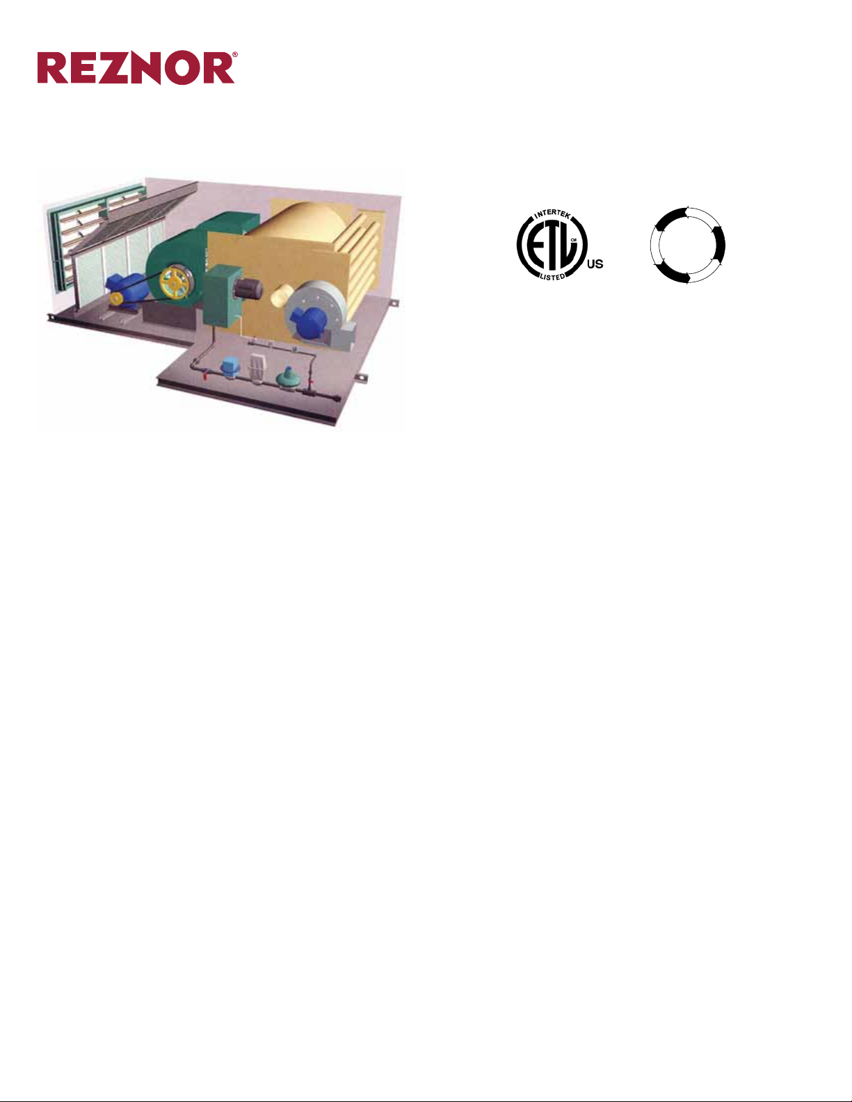
The Reznor Model PCD Series units are indirect-red/makeup air system designed for either indoor or outdoor
installation. Units can be congured for either vertical, horizontal for oor mount, outdoor pad mount, rooftop or
suspended installation. Select from top, bottom or horizontal discharge supply air options. Model PCD systems
are available to operate on either natural gas, propane or fuel oil. This catalog details features and specications for heating capacities ranging from 200 to 6,000 MBH output. Larger sizes are available on special order
basis (contact your Reznor Representative for more more information) High cfm versions (Model HPCD) are
also available.
The basic cabinet is constructed of 18 gauge galvaneal with a grey enamel nish. Other nishes are available.
The standard cabinet is a single wall with 1” thick, 1.5 lb. neoprene coated insulation. High density (2 lb.) insulation or 2” thick insulation can be selected. A 22 gauge interior liner is standard on the burner section. Optional
solid (for cleaning) or perforated (for sound attenuation) liners are available on other sections.
Vertical units (Model PCDV) can be shipped with a 3’ or 5’ mounting stand for eld attachment. The mounting
stand can be screened, or it can be insulated with one or two anged inlets with or without dampers. A louvered
inlet plenum can be shipped separately with outdoor vertical or horizontal units.
Discharge air openings can be shipped with two position motorized discharge dampers - low leak dampers also
available. Other air distribution options include trapezoidal cowls with horizontal louvers; 4-sided (360 degrees)
louvered discharge plenum; or 90 degree discharge cowls.
A 409 stainless steel primary and secondary heat exchanger is standard on Model PCD. Optional 304 stainless
steel can be substituted for both heat exchangers or only the primary heat exchanger. Model PCD high can be
ordered with a standard gravity vent or induced draft vent.
Units can be arranged for 100% outside or return air, or a mixing box can be specied with 3-position motorized dampers. Other modules can be included with Model PCD and shipped separately for eld attachment
including an inlet louvered hood, evaporative cooling section, lter cabinet, service platform and/or cooling coil
cabinet.
Model PCD and HPCD meet ETL (ANSI) Standards for installation in the United States and CGA (CSA) Standards for installation in Canada.
All units are factory wired, piped and test red.
● Single wall cabinet (with interior 22 gauge liner on burner section)
● Gray enamel nish on 18 gauge Galvaneal cabinet construction
● 1” thick 1.5 lb. neoprene coated berglass insulation
● Natural gas operation
● 409 stainless steel primary and secondary heat exchangers
● Gravity vent exhaust
● 230/1/60 supply voltage
● Burner manifold meets ETL (ANSI) or CGA (CSA) standards
● 3:1 turndown ratio modulating power burner
Form S-PCD Page 2
Page 3

MODELS PCD, HPCD (cont’d)
Page Number _______ of ______
OPTIONAL FEATURES Factory Installed
OPTIONAL FEATURES - Field
Installed
● 22 gauge solid or perforated interior cabinet metal liner on blower, lter, mixing box, or inlet plenum sec-
tions.
● Special material cabinet coating
● 1” thick high density (2 lb.) or 2” thick cabinet insulation
● Propane or fuel oil operation
● Power vent exhaust
● 304 stainless steel primary and secondary heat exchangers (or 304 primary with a 409 secondary stainless
steel heat exchanger)
● 208/3/60, 230/3/60, 460/3/60, or 575/3/60 supply voltages
● Vibration isolation
▬ 1” deection motor/blower spring vibration isolation
▬ 2” deection motor/blower spring vibration isolation
▬ Motor/blower rubber-in-shear isolation
▬ 1” external spring isolation under unit channel base
▬ 2” external spring isolation under unit channel base
▬ Seismic isolation, pad type
▬ External spring hangers - 1” deection
▬ External spring hangers - 2” deection
▬ Seismic isolation, hanger type
● Left or right hand controls
● Extended lube lines
● Vertical or horizontal unit conguration
● Top, bottom or horizontal supply discharge air
● Two position motorized discharge air shutoff damper, spring return (also available with low leak airfoil type
dampers)
● Outdoor units
▬ Weather-housing covers the control section on outdoor units
▬ Roof slopes away from weather-housing on Model PCDH 125 and larger
● Manifold meets IRI and/or FM requirements
● Up to 15:1 turndown ratio modulating burner
● UV ame supervision
● Unit mounted discharge temperature sensor
● Premium efciency ODP motors or TEFC motors
● Variable frequency drive
● Convenience outlet
● Rain-tight safety disconnect switch
● Service Platform
● Discharge air attachments
▬ Trapezoidal, 3 facet cowl with horizontal louvers (also available with double deection louvers)
▬ 4-sided (360 deg.) louvered discharge plenum
▬ 90 deg. or 45 deg. louvered nozzles
● 3’ or 5’ stand for vertical indoor units
▬ Screened mounting stand
▬ Insulated stand with one or two anged inlet air openings
▬ Insulated stand with one or two inlet openings with dampers
● Filter section (with 2” permanent or pleated lters)
▬ Flat lter rack
▬ V-bank lter rack
● Mixing box with 3-position motorized dampers.
● Louvered inlet plenum (for outdoor units)
● DX or chilled water coil for downstream installation
● Evaporative cooling module
▬ Available with stainless steel cabinet
▬ 12” thick Glasdek
▬ 1” or 2” aluminum mesh, washable lters
▬ Louvered inlet or screened inlet hood
▬ Fill and drain options
● Steam or hot water coil cabinet
● Gas pressure safety switch
● Adjustable freezestat
● Post and/or pre-purge timer
● 16” or 26” roof curb
● Remote Console
®
or Celdek® media
Form S-PCD Page 3
Page 4
UNIT CONFIGURATION
Page Number _______ of ______
Control Side and Air
Arrangement Data
As previously mentioned, Model PCD can be arranged for horizontal air ow or vertical (up) airow conguration. There are a variety of air discharge arrangements for each conguration (top, bottom or horizontal air
ow). Units can also be congured for left-hand or right-hand controls.
There are a variety of discharge air louvers, cowls and nozzles for supply air openings.
The following table will show you each available conguration and arrangement and the option codes repre-
senting each.
Control Side
Option AJ1 Left side controls (when facing air stream)
Option AJ2 Right side controls (when facing air stream)
Discharge Air Arrangement
Option AQ1 Bottom Discharge (Model PCDH)
Option AQ2 Horizontal Discharge (Model PCDH)
Option AQ13 Top Discharge (Model PCDV without Mounting Base), “L” Conguration
Option AQ32 Horizontal Discharge (Model PCDV without Mounting Base), “L” Conguration
Option AQ33 Horizontal Discharge (Model PCDV with Mounting Base), “I” Conguration
AQ34 Top Discharge (Model PCDV with Mounting Base), “I” Conguration
Note: No difference between left-hand and right-hand controls for units with Option AQ34. Unit can be set in place with controls
on proper side.
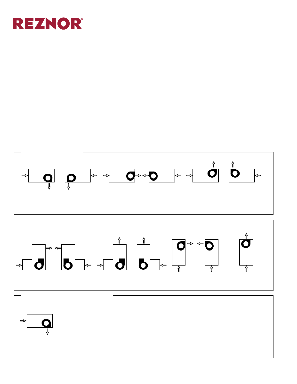
(H)PCDH Configurations
Typical Rooftop, Curb Mounted, or Indoor Suspended Heating or Makeup Air System.
AQ1 - AJ1 AQ1 - AJ2 AQ2 - AJ1 AQ2 - AJ2 AQ13 - AJ1 AQ13 - AJ2
(H)PCDV Configurations
(H)PCDV Uflow “L” Configuration - Typical Indoor, Thru-Wall, or Outdoor Slab Mount
Upflow Heating or Makeup Air System
AQ32
AQ33
-AJ1
AQ32
AQ33
-AJ2
AQ13
AQ34
-AJ1
AQ13
AQ34
-AJ2
(H)PCDV Uflow “I” Configuration* - Typical Indoor or Outdoor
Air Turnover High Bay Heating/Cooling Makeup Air System
AQ32
AQ33
-AJ1
AQ32
AQ33
-AJ2
AQ13
AQ34
Example Configuration Nomenclature
Air flow directions and control side illustrations as seen when facing the unit from
the control side
PCDH (Horizontal Configuration)
AQ1 Option - bottom discharge
AJ1 Option - Left side controls when facing air flow.
-AJ1
*
If (H)PCDV is ordered with an AVA option, the AW6 or AW15 V-bank lter section will stack on top of the AVA base in an “I” conguration. Otherwise, the V-bank lter section will be in the “L” conguration
shown. For draw through coil cabinets in the “L” conguration, order option AU5 or AU6. For blow through upow A-Coil cabinets in the “I” conguration, order option AU2A or AU3A.
Form S-PCD Page 4
Page 5
CONFIGURATION SELECTION
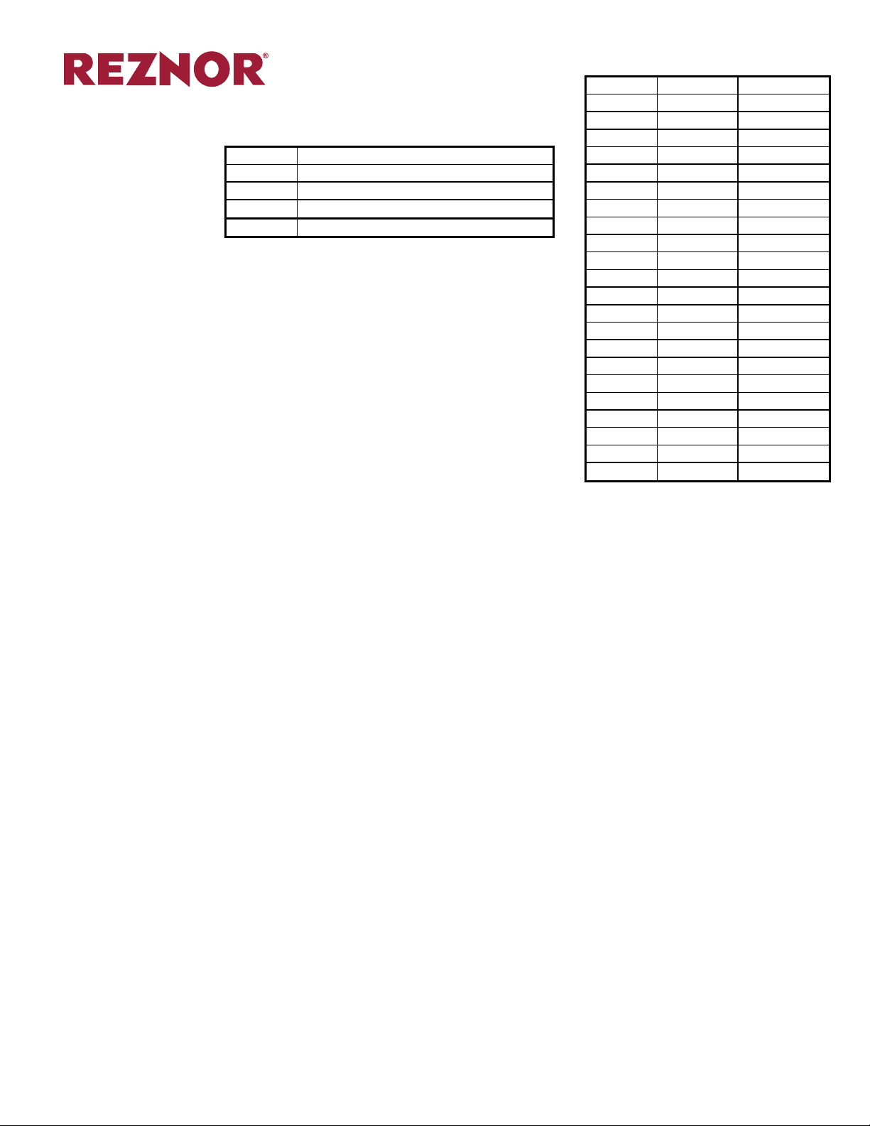
How to Specify a conguration
Model Description
PCDH Horizontal Indirect Fired Unit
HPCDH High CFM Horizontal Indirect Fired Unit
PCDV Vertical Indirect Fired Unit
HPCDV High CFM Vertical Indirect Fired Unit
Page Number _______ of ______
Size MBH Input MBH Output
20 250 200
25 312.5 250
35 437.5 350
40 500 400
45 562.5 450
55 687.5 550
65 812.5 650
75 937.5 750
85 1,062.5 850
100 1,250 1,000
125 1,562.5 1,250
150 1,875 1,500
175 2,187.5 1,750
200 2,500 2,000
250 3,125 2,500
275 3,437.5 2,750
300 3,750 3,000
325 4,062.5 3,250
350 4,375 3,500
400 5,000 4,000
500 6,250 5,000
600 7,500 6,000
SIZE SELECTION
How to determine the size of Model
PCD
Example 1: Make-Up Air
Model PCD are designated by their MBH output. Thus a PCD75 has 750 MBH output, or 750,000 BTUH.
● All PCD units are 80% efcient at high re, thus, output is BTUH input x 0.80
● Once you have chosen your required BTUH output, you can use BTUH output ÷ 0.80 to nd your required
input, or actual gas consumption. Using the desired output you can select your model.
● Choose your airow (this may be your rst step if the unit is applied in a make-up air situation)
● Calculate your TSP (add your ESP with your accessories – accessory pressure drops can be found after the
unit ESP table). With your airow and TSP selected you can nd your BHP from the performance table.
● Given the entering and leaving air dry bulb temperatures or temperature rise, the equation below can be
used to calculate the required MBH capacity
▬ MBH Capacity = (CFM x C x (LAT-EAT)) ÷ 0.80 ÷ 1000
▬ MBH capacity: BTUH/1000 (British Thermal Units per hour)
▬ CFM: Cubic Feet per Minute of air
▬ C: Gas constant of 1.08 based on air density at 75°F
▬ EAT: Entering air dry bulb temperature (°F)
▬ LAT: Leaving air dry bulb temperature (°F)
▬ 0.8: (80%) Series Efciency
A manufacturing facility needs pressurization via makeup air. A pressurization of 10% is deemed to be appropriate, and it is determined that 25,720 CFM exhaust is required. The design ambient is -20°F, and desired
discharge temperature is 70°F. Units will be roof mounted, down discharge, and will have an ESP of 0.60” w.c.
Select the appropriate size, and nd the BHP for the unit.
Selection:
● Since we are exhausting 25,720 CFM, and desire 10% pressurization, we can calculate that we need 28,300
CFM of supply air (25,720 x 110% = 28,300)
● We know our EAT = -20°F, and LAT = 70°F, thus we can calculate:
▬ MBH Output Capacity = (CFM x C x (LAT-EAT)) ÷ 1000
▬ MBH Output Capacity = (28,300 x 1.08 x (70 - (-20))) ÷ 1000
▬ MBH Output Capacity = 2,750.76
● The closest size available is the Model PCDH275 which has 2,750 MBH output, and 3,437.5 MBH input
We can now calculate our TSP:
● We are selecting the basic options – inlet lters and damper
● Inlet damper = 0.1” w.c.
● Inlet Filters = 0.3” w.c.
▬ TSP = ESP + Accessories
▬ TSP = 0.60 + 0.1 + 0.3
▬ TSP = 1.0” W.C.
● Consulting the chart for the PCD275 at 28,300 CFM and 1.0” W.C we nd our BHP = 16.28 BHP – Thus we
need a 20.0 HP motor minimum.
Form S-PCD Page 5
Page 6

How to Specify a conguration
Page Number _______ of ______
CONFIGURATION SELECTION (cont’d)
Example 2: Heat-Vent Unit
Selection:
Example 3: Heating Only Unit
A small warehouse needs a minimum of 20% fresh air in unoccupied (night time) mode and 100% fresh air in
occupied mode (during the day with forklift in the building). It has been calculated that at -30°F the room loses
1,000,000 BTUH. It has been determined that 11,000 CFM is required for the application. The outdoor air is
-30°F, and desired leaving air is 75°F. Return air will be 70°F. ESP is calculated to be 0.5” w.c. Select the appropriate model and nd the BHP for the unit.
Part 1 (Unoccupied mode)
● We only bring in 20% outside air in this mode, thus 2,200 CFM is outside air and 8,800 CFM is return air
● We know our EAT for outside air = -30°F, and LAT = 75°F, thus we can calculate:
▬ MBH Capacity = (CFM x C x (LAT - EAT)) ÷ 1000
▬ MBH Capacity = (2,200 x 1.08 x (75 - (-30))) ÷ 1000
▬ MBH Capacity = 249.48
● We also know that the room is losing 1,000 MBH, thus we need to add that to the calculation. Thus the total
Heat input capacity required = 1,250 MBH
● Before we select our model we must check the occupied mode to ensure we have sufcient heat capacity.
Part 2 (Occupied mode)
● We will be delivering 11,000 CFM of outside in this mode
● We know our EAT for outside air = -30°F, and LAT = 75°F, thus we can calculate:
▬ MBH Capacity = (CFM x C x (LAT - EAT)) ÷ 0.80 ÷ 1000
▬ MBH Capacity = (11,000 x 1.08 x (75 - (-30))) ÷ 0.80 ÷ 1000
▬ MBH Capacity = 1,247.40
● Thus to satisfy both options we need to use a PCDH125.
Note: In this example we are assuming there is an alternate source of heat that will be used during occupied
mode to make-up for the heat loss of the warehouse, which will not be used in unoccupied mode.
We can now calculate our TSP:
● We are selecting the basic options – inlet lters and damper
● Inlet damper = 0.1” w.c.
● Inlet Filters = 0.3” w.c.
▬ TSP = ESP + Accessories
▬ TSP = 0.50 + 0.1 + 0.3
▬ TSP = 0.9” W.C. (Round up to 1.0” w.c.)
● Consulting the chart for the PCDH125 at 11,000 CFM (use 11,574 CFM) and 1.0” w.c., we nd our BHP =
5.75 BHP – We can use a 7.5 hp motor.
A door heater for a large overhead door can potentially see 100% fresh air during times when the overhead
doors open frequently. Thus a durable Model PCD unit should be selected for this application. The appropriate
amount of air is determined to be 18,000 CFM at 0.5” w.c. for the vestibule, and 1,250 MBH is calculated to be
the appropriate amount of heat capacity required. Select the appropriate model and nd the BHP for the unit.
Selection:
● Since the heating load calculation has already been completed we simply need to use the heating capacity
and match it up with the appropriate Model PCD
● PCD125 is the appropriate model for 1,250 MBH
We can now calculate our TSP:
● We are selecting the basic options – inlet lters and damper
● Inlet damper = 0.1” w.c.
● Inlet Filters 0.3” w.c.
▬ TSP = ESP + Accessories
▬ TSP = 0.50 + 0.1 + 0.3
▬ TSP = 0.9” w.c. (Round up to 1.0” W.C)
● Consulting the chart for the PCD125 at 18,000 CFM (this value falls between 16,534 CFM and 19,290 CFM)
and 1.0” W.C we nd our BHP is between 9.59 BHP and 13.12 BHP. A 15 HP motor should be used.
Form S-PCD Page 6
Page 7
Page Number _______ of ______
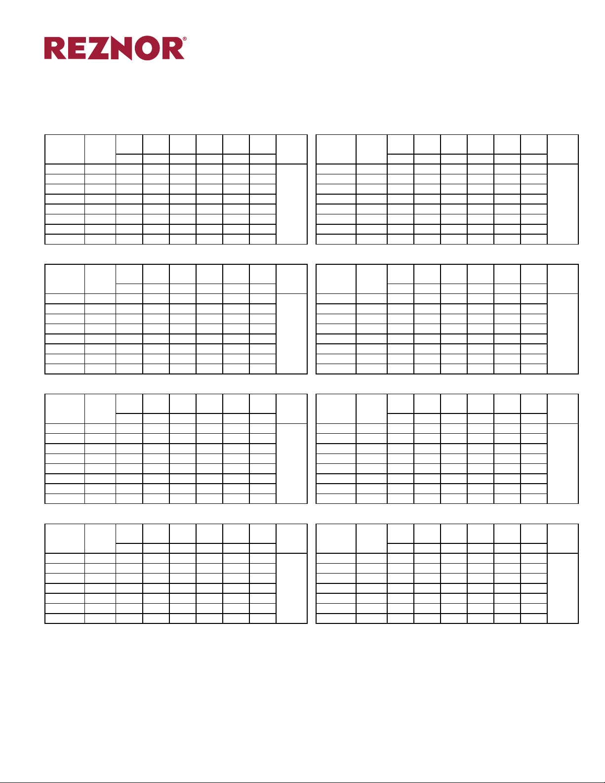
PERFORMANCE SPECIFICATION
Pressure Drop Table
Blower size will be determined by factory based on specied CFM and temperature rise requirements.
Note: The normal temperature rise for Model Series PCD is 71°-110°F; for Model Series HPCD it is 40°-70°F.
PCD20 - 250 MBH INPUT/200 MBH OUTPUT PCD25 - 312.5 MBH INPUT/250 MBH OUTPUT
0.25”
0.5”
0.75”
1.0”
1.5”
Air
Capacity
(CFM)
Temp.
Rise
W.C.
W.C.
W.C.
W.C.
W.C.
2.0”
W.C.
Inches
4630 40 1.70 1.94 2.17 2.42 2.94 4.28
3704 50 1.47 1.67 1.87 2.08 2.49 2.90 4630 50 1.70 1.94 2.17 2.42 2.94 4.28
3086 60 1.28 1.44 1.63 1.82 2.17 2.58 3858 60 1.62 1.82 2.02 2.24 2.67 3.09
2646 70 0.90 1.06 1.22 1.37 1.73 2.13 3307 70 1.53 1.66 1.87 2.08 2.46 2.83
2315 80 0.69 0.83 0.96 1.12 1.64 1.99 2894 80 1.09 1.27 1.44 1.61 1.95 2.37
2058 90 0.55 0.67 0.82 0.97 1.39 1.72 2572 90 0.85 1.01 1.16 1.3 1.67 2.27
1852 100 0.45 0.57 0.71 0.93 1.52 1.52 2315 100 0.69 0.83 0.96 1.12 1.64 1.99
1684 110 0.39 0.51 0.7 0.87 1.05 1.24 2104 11 0 0.58 0.69 0.84 0.99 1.43 1.79
PCD35 - 437.5 MBH INPUT/350 MBH OUTPUT PCD40 - 500 MBH INPUT/400 MBH OUTPUT
0.25”
0.5”
0.75”
1.0”
1.5”
Air
Capacity
(CFM)
Temp.
Rise
W.C.
W.C.
W.C.
W.C.
W.C
2.0”
W.C.
Inches
8102 40 4.49 4.93 5.37 5.82 6.73 7.66
6481 50 2.63 3.53 3.83 4.14 4.78 5.43 7407 50 3.59 4.00 5.22 5.56 6.27 7.00
5401 60 2.06 2.32 2.58 2.85 3.40 3.97 6173 60 2.35 3.14 3.43 3.73 4.34 4.97
4630 70 1.45 1.68 1.91 3.08 3.54 4.02 5291 70 1.96 2.21 2.47 2.73 3.28 3.84
4051 80 1.09 2.00 2.19 2.40 2.81 3.24 4630 80 1.45 1.68 1.91 2.15 2.64 3.99
3601 90 0.87 1.59 1.77 1.96 2.34 2.73 4115 90 1.12 1.33 1.54 1.76 2.80 3.26
3241 100 1.16 1.32 1.72 1.89 2.22 2.55 3704 100 1.36 1.53 1.72 1.93 2.34 2.74
2946 110 0.99 1.32 1.47 1.62 1.92 2.22
PCD45 - 562.5 MBH INPUT/450 MBH OUTPUT PCD55 - 687.5 MBH INPUT/550 MBH OUTPUT
0.25”
0.5”
0.75”
1.0”
1.5”
Air
Capacity
(CFM)
Temp.
Rise
W.C.
W.C.
W.C.
W.C.
W.C
2.0”
W.C.
Inches
10417 40 5.17 5.69 6.23 6.78 7.94 9.16
8333 50 4.13 4.57 5.02 5.48 6.40 8.31 10185 50 4.90 5.41 5.94 6.48 7.62 10.68
6944 60 2.68 3.06 3.44 4.46 5.12 5.81 8488 60 4.31 4.77 5.22 5.68 6.62 7.57
5952 70 1.90 2.66 2.94 3.22 3.81 4.42 7275 70 2.98 3.38 3.77 4.17 4.99 5.83
5208 80 1.75 1.99 2.24 2.50 3.03 3.58 6366 80 2.21 3.12 3.40 3.70 4.32 4.96
4630 90 1.34 1.57 1.80 2.03 2.52 3.04 5658 90 1.71 2.38 2.64 2.92 3.48 4.06
4167 100 1.07 1.28 2.09 2.32 2.77 3.24 5093 100 1.66 1.90 2.15 2.40 2.92 3.52
3788 110 1.39 1.54 1.74 1.93 2.37 3.39 4630 110 1.34 1.57 1.80 2.77 3.23 3.70
PCD65 - 812.5 MBH INPUT/650 MBH OUTPUT PCD75 - 937.5 MBH INPUT/750 MBH OUTPUT
0.25”
0.5”
0.75”
1.0”
1.5”
Air
Capacity
(CFM)
Temp.
Rise
W.C.
W.C.
W.C.
W.C.
W.C
2.0”
W.C.
Inches
12037 50 5.82 6.39 6.97 7.57 8.79 10.03
10031 60 3.73 4.22 4.72 7.31 8.31 9.32 11574 60 5.27 5.82 6.39 6.96 8.14 9.35
8598 70 2.64 4.47 4.89 5.32 6.19 7.09 9921 70 3.64 4.13 4.62 5.13 6.18 8.94
7523 80 2.00 3.36 3.74 4.12 4.91 5.72 8681 80 2.70 4.37 4.79 5.22 6.11 7.01
6687 90 2.34 2.67 3.53 3.87 4.56 5.24 7716 90 2.11 3.35 3.74 4.13 4.93 5.76
6019 100 1.91 2.59 2.90 3.21 3.83 4.53 6944 100 2.33 2.67 3.03
5471 110 1.89 2.17 2.45 2.73 3.29 4.85 6313 110 1.89 2.65 2.97 3.29 3.94 4.58
Gas
Conn.
Capacity
(CFM)
Air
Temp.
Rise
0.25”
W.C.
0.5”
W.C.
0.75”
W.C.
1.0”
W.C.
5787 40 2.91 3.19 3.48 3.77 4.37 4.99
1
0.25”
0.5”
0.75”
Gas
Conn.
Capacity
(CFM)
Air
Temp.
Rise
W.C.
W.C.
W.C.
1.0”
W.C.
9259 40 7.13 6.62 10.33 10.77 11.78 12.82
1
3367 110 1.08 1.26 1.44 1.63 1.99 2.81
0.25”
0.5”
0.75”
Gas
Conn.
Capacity
(CFM)
Air
Temp.
Rise
W.C.
W.C.
W.C.
1.0”
W.C.
12731 40 7.24 7.98 8.79 9.61 11.40 19.59
1
0.25”
0.5”
0.75”
Gas
Conn.
Capacity
(CFM)
Air
Temp.
Rise
W.C.
W.C.
W.C.
1.0”
W.C.
13889 50 8.39 9.02 8.82 10.35 11.72 13.12
1
3.39 4.13 5.39
1.5”
W.C
1.5”
W.C.
1.5”
W.C
1.5”
W.C
2.0”
W.C.
2.0”
W.C.
2.0”
W.C.
2.0”
W.C.
Gas
Conn.
InchesBHP BHP BHP BHP BHP BHP BHP BHP BHP BHP BHP BHP
1
Gas
Conn.
InchesBHP BHP BHP BHP BHP BHP BHP BHP BHP BHP BHP BHP
1
Gas
Conn.
InchesBHP BHP BHP BHP BHP BHP BHP BHP BHP BHP BHP BHP
1
Gas
Conn.
InchesBHP BHP BHP BHP BHP BHP BHP BHP BHP BHP BHP BHP
1
NOTES:
-All Static Values Include the Blower, Burner, and Casing
-Accesory Static Values Must be Added to Obtain the Total Static
-Brake Horsepower Does Not Include Drive Losses
Consult factory representative for:
-Higher Air Capacities or Special Applications
-Performance Data on Higher Statics than Listed
-Performance Data at Elevations Other Than Sea Level
Form S-PCD Page 7
Page 8
Page Number _______ of ______
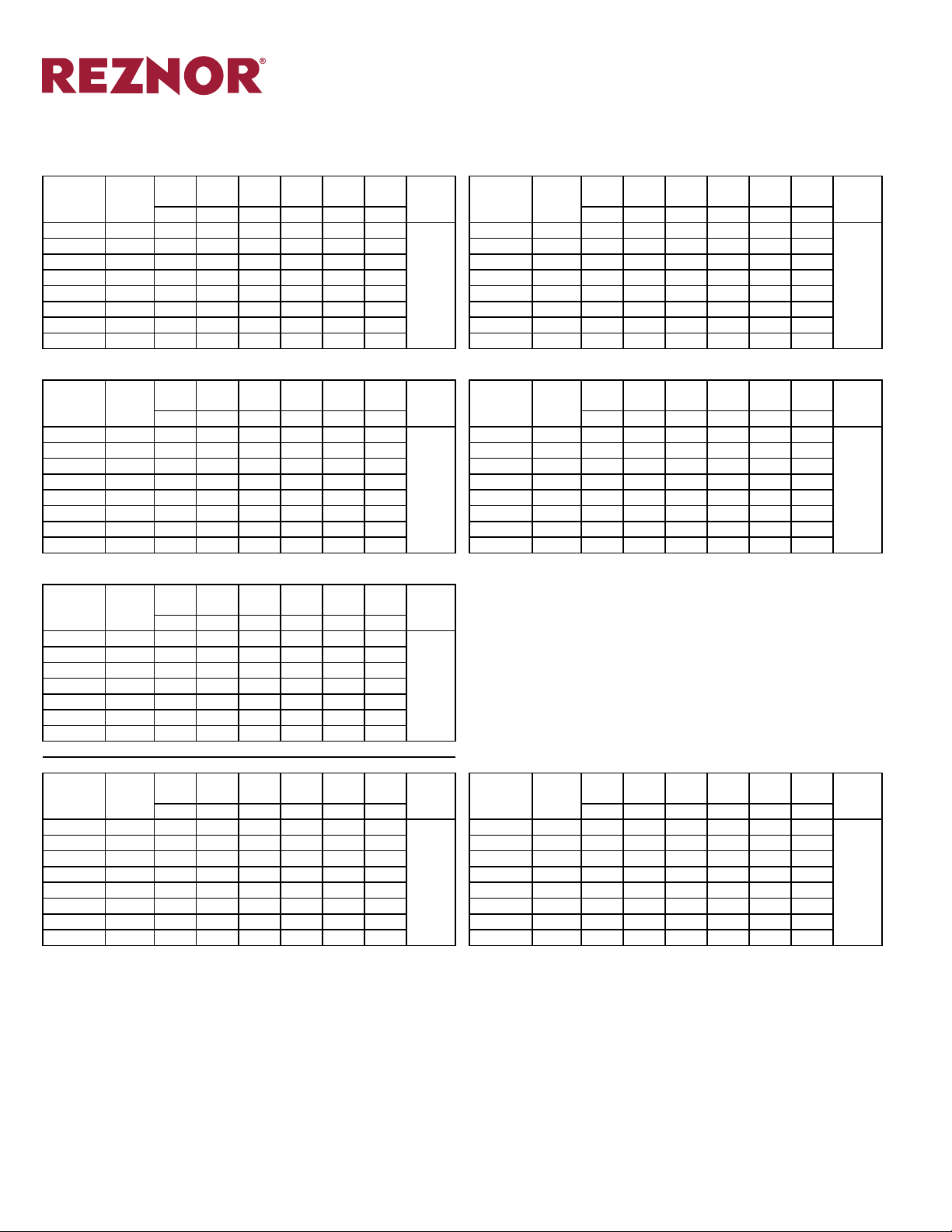
PERFORMANCE SPECIFICATION (cont’d)
Pressure Drop Table
PCD85 - 1062.5 MBH INPUT/850 MBH OUTPUT PCD100 - 1250 MBH INPUT/1000 MBH OUTPUT
0.25”
0.5”
0.75”
1.0”
1.5”
Air
W.C.
W.C.
W.C.
Capacity
(CFM)
Temp.
Rise
W.C.
19676 40 12.83 13.87 14.93 15.99 18.13 20.30
W.C.
2.0”
W.C.
Gas
Conn.
Inches
Air
Capacity
Temp.
(CFM)
23148 40 17.14 18.22 19.33 20.43 22.71 25.00
15741 50 7.35 8.20 9.05 9.91 11.67 13.45 18519 50 10.97 11.96 12.96 13.96 15.99 18.04
13117 60 4.82 5.54 7.36 7.98 9.25 10.56 15432 60 7.02 7.85 8.69 9.54 11.26 13.02
11243 70 3.46 4.75 5.29 5.84 6.96 8.13 13228 70 4.89 5.62 7.49 8.10 9.38 10.70
9838 80 3.10 3.57 4.05 4.54 5.56 8.49 11574 80 3.66 5.05 5.60 6.16 7.31 8.50
1
8745 90 2.41 2.84 4.74 5.16 6.04 7.95 10288 90 3.45 3.93 4.43 4.94 5.99 9.03
7870 100 1.94 3.55 3.84 4.23 5.04 5.87 9259 100 2.72 3.17 3.63 5.58 6.49 7.44
7155 110 1.61 2.86 3.21 3.58 4.33 5.68 8418 110 2.22 2.64 4.17 4.59 5.44 6.32
PCD125 - 1562.5 MBH INPUT/1250 MBH OUTPUT PCD150 - 1875 MBH INPUT/1500 MBH OUTPUT
0.25”
0.5”
0.75”
1.0”
1.5”
Air
W.C.
W.C.
W.C.
Capacity
(CFM)
Temp.
Rise
W.C.
28935 40 16.22 17.62 19.04 20.51 23.54 26.74
W.C.
2.0”
W.C.
Gas
Conn.
Inches
Air
Capacity
Temp.
(CFM)
34722 40 24.50 28.64 29.94 31.31 34.04 36.90
23148 50 10.76 11.82 12.91 14.02 16.35 18.79 27778 50 14.66 18.40 19.66 20.95 23.59 26.33
19290 60 6.92 7.84 12.09 13.12 15.20 17.30 23148 60 10.76 11.82 12.91 14.02 16.35 18.79
16534 70 4.90 7.81 8.70 9.59 11.39 13.23 19841 70 7.39 8.32 9.29 13.93 16.05 18.21
14468 80 5.10 5.87 6.65 7.45 9.05 10.70 17361 80 5.46 6.30 9.63 10.57 12.45 14.37
1-1/4”
12860 90 3.97 4.66 6.51 7.08 8.31 9.59 15432 90 4.23 6.72 7.55 8.39 10.09 11.82
11574 100 3.21 4.68 5.20 5.75
6.89 8.07 13889 100 4.68 5.43 6.18 8.34 9.63 10.98
10522 110 2.65 3.80 4.30 4.81 5.87 6.97 12626 110 3.81 4.49 6.24 6.81 8.03 9.28
PCD175 - 2187.5 MBH INPUT/1750 MBH OUTPUT
0.25”
0.5”
0.75”
1.0”
1.5”
Air
Capacity
(CFM)
Temp.
Rise
W.C.
W.C.
W.C.
W.C.
BHP BHP BHP BHP BHP BHP
W.C.
2.0”
W.C.
Gas
Conn.
Inches
32407 50 21.80 23.34 24.90 26.50 29.79 33.22
27006 60 13.62 17.11 18.35 19.61 22.19 24.88
23148 70 10.76 11.82 12.91 14.02 16.35 18.79
20255 80 7.77 8.72 9.70 10.72 12.86 15.14
1-1/2”
NOTES:
-All Static Values Include the Blower, Burner, and Casing
-Accesory Static Values Must be Added to Obtain the Total Static
-Brake Horsepower Does Not Include Drive Losses
Consult factory representative for:
-Higher Air Capacities or Special Applications
-Performance Data on Higher Statics than Listed
-Performance Data at Elevations Other Than Sea Level
18004 90 5.91 6.78 10.40 11.36 13.31 15.29
16204 100 4.70 7.48 8.35 9.22 11.00 12.80
14731 110 3.85 6.10 6.90 7.70 9.33 11.00
PCD200 - 2500 MBH INPUT/2000 MBH OUTPUT PCD250 - 3125 MBH INPUT/2500 MBH OUTPUT
0.25”
0.5”
0.75”
1.0”
1.5”
Air
W.C.
W.C.
W.C.
Capacity
(CFM)
Temp.
Rise
W.C.
46296 40 22.66 24.60 26.59 28.65 33.03 43.86
W.C.
2.0”
W.C.
Gas
Conn.
Inches
Air
Capacity
Temp.
(CFM)
57870 40 35.59 38.28 41.04 43.88 49.81 56.07
37037 50 16.18 17.89 19.64 21.46 25.24 29.26 46296 50 22.66 24.60 26.59 28.65 33.03 43.86
30864 60 10.50 11.98 18.83 20.30 23.32 26.48 38580 60 17.89 19.67 21.48 23.34 27.23 31.34
26455 70 7.48 12.13 13.40 16.70 19.16 21.73 33069 70 12.31 13.87 22.10 23.65 26.84 30.14
23148 80 7.95 10.46 11.52 12.60 14.84 17.21 28935 80 9.08 14.91 16.28 17.67 20.56 23.60
20576 90 6.12 8.05 9.01 10.01
12.10 14.33 25720 90 7.08 11.42 14.56 15.74 18.15 20.67
1-1/2”
18519 100 5.62 6.47 7.37 8.30 13.24 15.26 23148 100 7.95 10.46 11.52 12.60 14.84 17.21
16835 110 4.56 5.36 8.41 9.31 11.14 13.00 21044 110 6.43 8.46 9.44 10.45 12.56 14.82
Rise
Rise
Rise
0.25”
W.C.
0.25”
W.C.
0.25”
W.C.
0.5”
W.C.
0.5”
W.C.
0.5”
W.C.
0.75”
W.C.
0.75”
W.C.
0.75”
W.C.
1.0”
W.C.
1.0”
W.C.
1.0”
W.C.
1.5”
W.C.
1.5”
W.C.
1.5”
W.C.
2.0”
W.C.
2.0”
W.C.
2.0”
W.C.
Gas
Conn.
InchesBHP BHP BHP BHP BHP BHP BHP BHP BHP BHP BHP BHP
1-1/4”
Gas
Conn.
InchesBHP BHP BHP BHP BHP BHP BHP BHP BHP BHP BHP BHP
1-1/2”
Gas
Conn.
InchesBHP BHP BHP BHP BHP BHP BHP BHP BHP BHP BHP BHP
2”
Form S-PCD Page 8
Page 9
Page Number _______ of ______
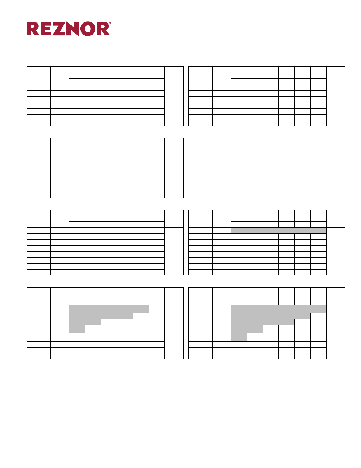
PERFORMANCE SPECIFICATION (cont’d)
Pressure Drop Table
PCD275 - 3437.5 MBH INPUT/2750 MBH OUTPUT PCD300 - 3750 MBH INPUT/3000 MBH OUTPUT
0.25”
0.5”
0.75”
1.0”
1.5”
Air
W.C.
W.C.
W.C.
Capacity
(CFM)
Temp.
Rise
W.C.
50926 50 25.65 27.71 29.79 31.90 36.30 40.99
W.C.
2.0”
W.C.
Gas
Conn.
Inches
Air
Capacity
Temp.
(CFM)
55556 50 28.02 30.52 33.08 35.71 41.22 47.07
42438 60 16.62 22.96 24.90 26.86 30.92 38.36 46296 60 20.61 22.51 24.44 26.43 30.62 35.17
36376 70 14.36 16.02 17.72 19.47 23.14 27.04 39683 70 14.12 19.58 21.41 23.27 27.15 31.23
31829 80 10.18 11.65 18.78 20.25 23.28 26.43 34722 80 12.89 14.48 16.12 17.82 21.40 25.22
2”
28292 90 8.08 9.44 14.93 16.28 19.10 22.07 30864 90 9.81 11.26 18.13 19.59 22.58 25.71
25463 100 6.52 10.76 11.98 15.01 17.39 19.87 27778 100 7.77 13.03 14.34 15.68 18.46 21.40
23148 110 7.65 8.75 11.22 12.30 14.52 16.87 25253 11 0 6.38 10.53 13.56 14.71 17.08 19.55
PCD325 - 4062.5 MBH INPUT/3250 MBH OUTPUT
0.25”
0.5”
0.75”
1.0”
1.5”
Air
Capacity
(CFM)
Temp.
Rise
W.C.
W.C.
W.C.
W.C.
BHP BHP BHP BHP BHP BHP
W.C.
2.0”
W.C.
Gas
Conn.
Inches
60185 50 34.40 37.07 39.79 42.58 48.37 54.48
50154 60 25.26 27.31 29.38 31.48 35.86 40.52
42989 70 17.13 18.91 20.73 27.59 31.68 35.96
37616 80 15.59 17.30 19.04 20.84 24.58 28.55
2-1/2”
NOTES:
-All Static Values Include the Blower, Burner, and Casing
-Accesory Static Values Must be Added to Obtain the Total Static
-Brake Horsepower Does Not Include Drive Losses
Consult factory representative for:
-Higher Air Capacities or Special Applications
-Performance Data on Higher Statics than Listed
-Performance Data at Elevations Other Than Sea Level
33436 90 11.78 13.32 14.92 23.37 26.55 29.85
30093 100 9.29 10.72 17.15 18.58 21.52 24.60
27357 110 7.55 12.62 13.91 17.52 20.03 22.64
PCD350 - 4375 MBH INPUT/3500 MBH OUTPUT PCD400 - 5000 MBH INPUT/4000 MBH OUTPUT
0.25”
0.5”
0.75”
1.0”
1.5”
Air
W.C.
W.C.
W.C.
Capacity
(CFM)
Temp.
Rise
W.C.
81019 40 48.29 51.64 55.00 58.39 65.33 72.56
W.C.
2.0”
W.C.
Gas
Conn.
Inches
Air
Capacity
Temp.
(CFM)
92593 40 CONSULT FACTORy
64815 50 29.42 32.21 35.04 37.92 43.92 54.90 74074 50 41.31 44.50 47.68 50.90 57.47 64.32
54012 60 21.86 24.20 26.59 29.04 34.15 39.61 61728 60 26.05 28.72 35.91 38.63 44.22 40.07
46296 70 15.21 20.08 21.98 23.90 27.90 32.21 52910 70 20.86 23.16 25.51 27.92 32.99 38.40
40509 80 13.18 14.84 20.55 22.41 26.24 30.27 46296 80 15.21 20.08 21.98 23.90 27.90 32.21
2-1/2”
36008 90 10.07 14.39 16.05 17.74 21.30 25.10 41152 90 13.69 15.37 21.28 23.16 27.04 31.11
32407 100 10.02 11.50 13.02 20.82 23.90 27.09 37037 100 10.72 15.30 16.99 18.72 22.34 26.19
29461 110 8.12 9.49 15.60 16.98 19.85 22.85 33670 11 0 10.90 12.43 14.00 15.62 25.81 22.73
PCD500 - 6250 MBH INPUT/5000 MBH OUTPUT PCD600 - 7500 MBH INPUT/6000 MBH OUTPUT
0.25”
0.5”
0.75”
1.0”
1.5”
Air
W.C.
W.C.
W.C.
Capacity
(CFM)
Temp.
Rise
W.C.
115741 40 CONSULT FACTORY, REQUIRES 139.7
W.C.
2.0”
W.C.
Gas
Conn.
Inches
Air
Capacity
Temp.
(CFM)
138889 40
92593 50 FAN SIZE GREATER THAN 77.06 84.76 111111 50 CONSULT FACTORY, REQUIRES 127.1
77160 60 2 - 36x36 42.40 49.27 55.92 62.71 92593 60 FAN SIZE GREATER THAN 77.06 84.76
66138 70 29.63 32.48 40.88 46.66 52.60 79365 70 2 - 36x36 45.35 52.60 59.43 66.37
57870 80 19.47 21.95 28.17 41.38 35.91 41.38 69444 80 30.61 36.18 37.17 45.24 51.58
3”
51440 90 14.86 19.69 21.95 28.06 32.30 36.69 61728 90 20.87 25.31 32.48 35.16 40.61 46.29
46296 100 13.76 15.77 20.61 28.34 32.55 36.87 55556 100 17.69 23.37 25.78 33.23 37.78 42.41
42088 110 11.13 15.11 16.84 23.11 27.01 31.07 50505 110 14.24 18.89 24.88 26.95 31.12 35.47
Rise
Rise
Rise
0.25”
W.C.
0.25”
W.C.
0.25”
W.C.
0.5”
W.C.
0.5”
W.C.
0.5”
W.C.
0.75”
W.C.
0.75”
W.C.
0.75”
W.C.
1.0”
W.C.
1.0”
W.C.
1.0”
W.C.
1.5”
W.C.
1.5”
W.C.
1.5”
W.C.
2.0”
W.C.
2.0”
W.C.
2.0”
W.C.
Gas
Conn.
InchesBHP BHP BHP BHP BHP BHP BHP BHP BHP BHP BHP BHP
2-1/2”
Gas
Conn.
InchesBHP BHP BHP BHP BHP BHP BHP BHP BHP BHP BHP BHP
3”
Gas
Conn.
InchesBHP BHP BHP BHP BHP BHP BHP BHP BHP BHP BHP BHP
3”
Form S-PCD Page 9
Page 10

Page Number _______ of ______
PERFORMANCE SPECIFICATION (cont’d)
STATIC PRESSURE DROP FOR ACCESSORIES
ACCESSORIES
FLAT AND ANGULAR FILTER SECTION 0.4
V-BANK FILTER SECTION 0.6
INLET HOOD 0.1
INLET LOUVER 0.2
EVAPORATIVE COOLER 0.3
INLET DAMPER 0.1
DX PLENUM AND COIL 0.6
MIX BOX W/FILTERS 0.7
HORIZONTAL DISCHARGE HEAD 0.5
4-WAY DISCHARGE HEAD 0.5
NOTES: • Accessory Static Pressure Drops are Calculated at Maximum CFM Loads.
STATIC PRESSURE DROP
(w.c.)
Form S-PCD Page 10
Page 11
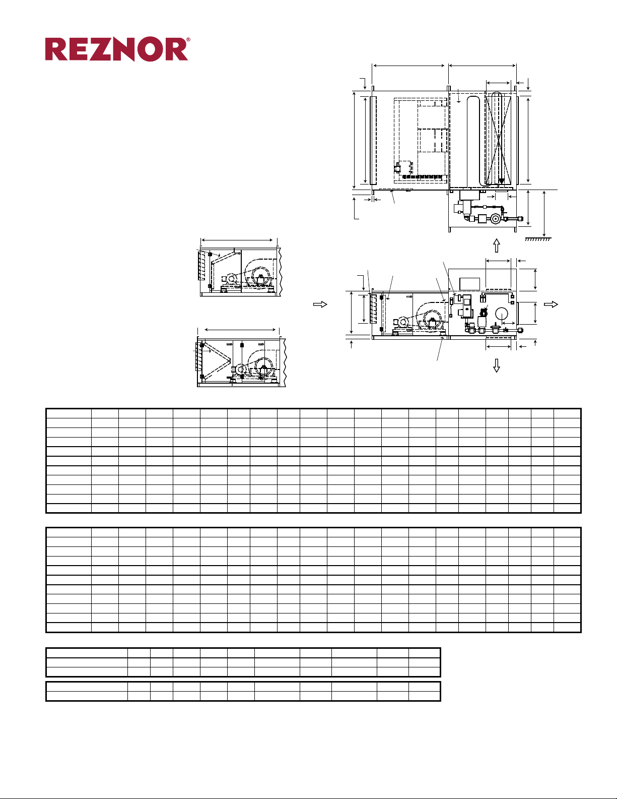
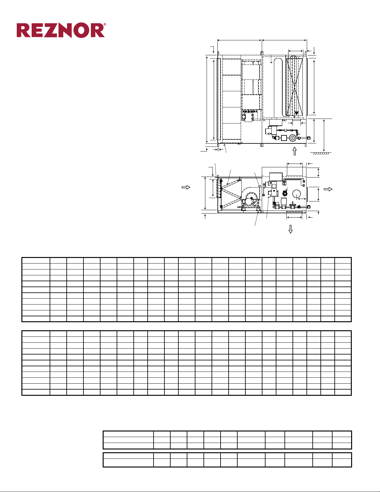
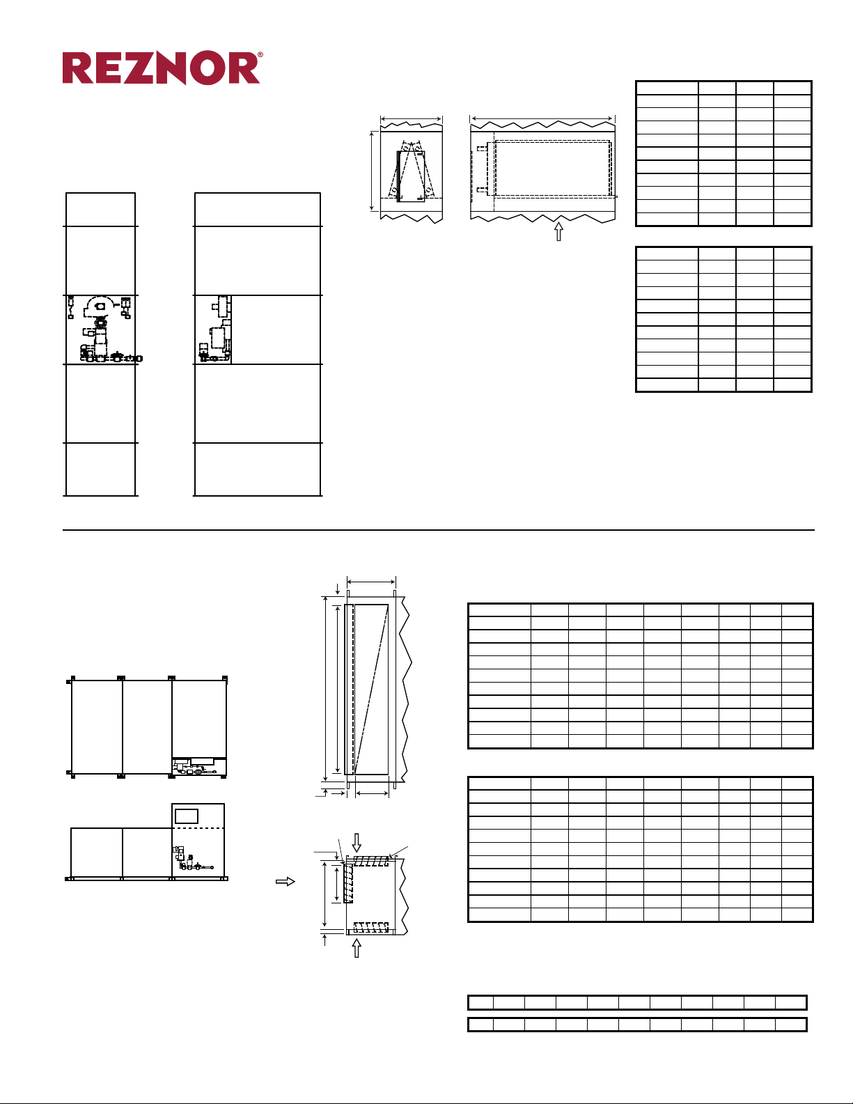
PCDH Basic Horizontal Unit
ANGLED
Burner Section and Blower/Filter Section only
±1/8” (3mm)
DIMENSIONS
U
BLOWER/FILTER
SECTION
1
A
Page Number _______ of ______
HEAT EXCHANGER
SECTION
B
FOUR PASS
COMBUSTION
CHAMBER
E
U
The illiustration to the right shows Model
PCDH. On the following pages are di-
C
L
BLOWERS
H
mension drawings for the high cfm horizontal unit, Model HPCDH, vertical unit,
Model PCDV, and the high cfm vertical
COMBUSTION PATH
unit, Model HPCDV.
Following those pages are dimension
data for modular options.
Dimensions are shown in inches and
(millimeters).
FILTER
V-BANK
FILTER
Dimensions ±1/8”
Sizes A
1
2
A
B C D E F G H K L M N P T U V W Z
BLOWER/FILTER
SECTION
1
A
MOTOR
BLOWER/FILTER
SECTION
2
A
MOTOR
Typ. 4”
(102mm)
OUTDOOR AIR
DAMPER
3”
(76mm)
FRESH AIR
FLOW
M
D
V
* Burner Section and Blower Section on Sizes 65 and greater
are split and shipped separately for eld attachment.
Z
FL AT
FILTER
SIDE VIEW
HINGED DOOR
ACCESS
HANDLE
TOP VIEW
MOTOR
SPRING
ISOLATOR
C/W
POWER
BURNER
FLEX
CONN.
SUPPLY AIR
CONTROL
PANEL
20/25 52 62 47 32 32 18 7 30 23 18 23 19 56 18 10 4 1/2 3 8 1 3/8
35/40 60 68 47 48 32 18 7 30 39 18 39 19 56 18 10 4 1/2 3 8 1 3/8
45/55 67 72 55 60 36 20 9 30 51 18 51 23 56 18 12 4 1/2 3 10 1 3/8
65/75 62 67 55 80 36 20 9 30 71 18 71 23 56 18 12 4 1/2 3 10 1 3/8
85/100 68 75 62 80 48 20 15 30 71 18 71 35 56 12 12 4 1/2 4 12 1 9/16
125/150/175 75 85 72 100 54 30 15 32 91 24 91 41 56 12 12 4 1/2 4 12 1 9/16
200/250 80 92 72 120 60 32 15 36 111 30 111 47 56 12 12 1/2 4 1/2 4 12 1 9/16
275/300/325 87 95 84 140 65 32 17 1/2 36 131 30 131 52 56 12 14 4 1/2 4 14 1 9/16
350/400 92 101 100 160 70 32 20 36 148 30 148 57 56 - 11 1/2 6 6 16 2
500/600 107 117 141 180 80 32 16 36 168 48 168 67 56 - 14 6 6 18 2
Dimensions (±3mm)
Sizes A
1
2
A
B C D E F G H K L M N P T U V W Z
20/25 (1,321) (1,575) (1,194) (813) (813) (457) (178) (762) (584) (457) (584) (483) (1,422) (457) (254) (114) (76) (203) (35)
35/40 (1,524) (1,727) (1,194) (1,219) (813) (457) (178) (762) (991) (457) (991) (483) (1,422) (457) (254) (114) (76) (203) (35)
45/55 (1,702) (1,829) (1,397) (1,524) (914) (508) (229) (762) (1,295) (457) (1,295) (584) (1,422) (457) (305) (114) (76) (254) (35)
65/75 (1,575) (1,702) (1,397) (2,032) (914) (508) (229) (762) (1,803) (457) (1,803) (584) (1,422) (457) (305) (114) (76) (254) (35)
85/100 (1,727) (1,905) (1,575) (2,032) (1,219) (508) (381) (762) (1,803) (457) (1,803) (889) (1,422) (305) (305) (114) (102) (305) (40)
125/150/175 (1,905) (2,159) (1,829) (2,540) (1,372) (762) (381) (813) (2,311) (610) (2,311) (1,041) (1,422) (305) (305) (114) (102) (305) (40)
200/250 (2,032) (2,337) (1,829) (3,048) (1,524) (813) (381) (914) (2,819) (762) (2,819) (1,194) (1,422)
(305) (318) (114) (102) (305) (40)
275/300/325 (2,210) (2,413) (2,134) (3,556) (1,651) (813) (445) (914) (3,327) (762) (3,327) (1,321) (1,422) (305) (356) (114) (102) (356) (40)
350/400 (2,337) (2,565) (2,540) (4,064) (1,778) (813) (508) (914) (3,759) (762) (3,759) (1,448) (1,422) - (292) (152) (152) (406) (51)
500/600 (2,718) (2,972) (3,581) (4,572) (2,032) (813) (406) (914) (4,267) (1,219) (4,267) (1,702) (1,422) - (356) (152) (152) (457) (51)
OPTION
PUFF
DOOR
W
U
E
T
E
U
SUPPLY AIR
OPTION
G
P
K
F
N
MINIMUM
CLEARANCE
SUPPLY AIR
OPTION
20/25 35/40 45/55 65/75 85/100 125/150/175 200/250 275/300/325 350/400 500/600
Base Weight Lbs. 1,510 1,900 2,375 3,055 3,810 5,335 6,700 8,590 10,280 15,170
with V-Bank Filter Rack 1,675 1,980 2,480 3,220 3,990 5,390 6,765 8,655 10,365 15,295
Base Weight (kg) (685) (862) (1077) (1386) (1728) (2420) (3039) (3896) (4663) (6881)
with V-Bank Filter Rack (760) (898) (1125) (1461) (1810) (2445) (3069) (3926) (4702) (6938)
Note: Dimension A1, Blower Section, includes standard at lter rack. Optional angled lter rack may
be substituted at manufacturer’s discretion. Angle lter rack section does not change unit dimensions.
Dimension A2 indicates length of blower cabinet with V-Bank Filters.
Form S-PCD Page 11
Page 12
HPCDH Basic Horizontal Unit (Indoor Unit)
Burner Section and Blower/Filter Section only
±1/8” (3mm)
DIMENSIONS (cont’d)
U
C
L
BLOWER/FILTER
SECTION
2
A1, A
BLOWERS
TOP VIEW
FOUR PASS
COMBUSTION
CHAMBER
Page Number _______ of ______
HEAT EXCHANGER
SECTION
B
E
U
H
COMBUSTION PATH
MOTOR
W
G
N
MINIMUM
CLEARANCE
Typ. 4”
(102mm)
OUTDOOR AIR
OUTDOOR
AIR
FLOW
DAMPER
(76mm)
D
HINGED DOOR
C/W
ACCESS
Z
HANDLE
3”
FILTERS
FLEX
CONN.
M
SUPPLY AIR
OPTION
CONTROL
PANEL
PUFF
DOOR
E
U
P
SUPPLY AIR
K
T
OPTION
F
V
U
E
SUPPLY AIR
OPTION
Dimensions ±1/8”
Sizes A
SIDE VIEW
SPRING
ISOLATOR
* Burner Section and Blower Section on Sizes 65 and greater
are split and shipped separately for eld attachment.
1
2
A
B C D E F G H K L M N P T U V W Z
POWER
BURNER
20/25 37 52 47 62 38 18 9 30 23 18 53 19 56 12 10 4 1/2 3 8 1 3/8
35/40 40 55 47 78 38 18 9 30 39 18 69 19 56 12 10 4 1/2 3 8 1 3/8
45/55 47 60 55 90 42 20 11 30 51 18 81 23 56 12 12 4 1/2 3 10 1 3/8
65/75 47 55 55 110 42 20 12 30 71 18 101 23 56 8 12 4 1/2 3 10 1 3/8
85/100 50 60 62 110 54 20 18 30 71 18 101 35 56 4 12 4 1/2 4 12 1 9/16
125/150/175 57 84 72 132 60 30 18 32 91 24 123 41 56 6 12 4 1/2 4 12 1 9/16
200/250 60 90 72 156 66 32 17 1/2 36 111 30 147 47 56 6 12 1/2 4 1/2 4 12 1 9/16
275/300/325 65 95 84 176 71 32 20 36 131 30 167 52 56 6 14 4 1/2 4 14 1 9/16
350/400 68 98 100 196 76 32 27 1/2 36 148 30 184 57 56 - 11 1/2 6 6 16 2
500/600 77 102 141 216 86 32 21 36 168 48 204 67 56 - 14 6 6 18 2
Dimensions (±3mm)
Sizes A
1
2
A
B C D E F G H K L M N P T U V W Z
20/25 (940) (1,321) (1,194) (1,575) (965) (457) (229) (762) (584) (457) (1,346) (483) (1,422) (305) (254) (114) (76) (203) (35)
35/40 (1,016) (1,397) (1,194) (1,981) (965) (457) (229) (762) (991) (457) (1,753) (483) (1,422) (305) (254) (114) (76) (203) (35)
45/55 (1,194) (1,524) (1,397) (2,286) (1,067) (508) (279) (762) (1,295) (457) (2,057) (584) (1,422) (305) (305) (114) (76) (254) (35)
65/75 (1,194) (1,397) (1,397) (2,794) (1,067) (508) (305) (762) (1,803) (457) (2,565) (584) (1,422) (203) (305) (114) (76) (254) (35)
85/100 (1,270) (1,524) (1,575) (2,794) (1,372) (508) (457) (762) (1,803) (457) (2,565) (889) (1,422) (102) (305) (114) (102) (305) (40)
125/150/175 (1,448) (2,134) (1,829) (3,353) (1,524) (762) (457) (813) (2,311) (610) (3,124) (1,041) (1,422) (152) (305) (114) (102) (305) (40)
200/250 (1,524) (2,286) (1,829) (3,962) (1,676) (813) (445) (914) (2,819) (762) (3,734) (1,194) (1,422)
(152) (318) (114) (102) (305) (40)
275/300/325 (1,651) (2,413) (2,134) (4,470) (1,803) (813) (508) (914) (3,327) (762) (4,242) (1,321) (1,422) (152) (356) (114) (102) (356) (40)
350/400 (1,727) (2,489) (2,540) (4,978) (1,930) (813) (699) (914) (3,759) (762) (4,674) (1,448) (1,422) - (292) (152) (152) (406) (51)
500/600 (1,956) (2,591) (3,581) (5,486) (2,184) (813) (533) (914) (4,267) (1,219) (5,182) (1,702) (1,422) - (356) (152) (152) (457) (51)
Note: Dimension A1, Blower Section, includes at lter rack. Optional angled lter rack does not change
unit dimensions. Dimension A2 indicates length of blower cabinet with V-Bank Filters.
20/25 35/40 45/55 65/75 85/100 125/150/175 200/250 275/300/325 350/400 500/600
Base Weight Lbs. 1,770 2,265 2,865 3,565 2,548 5,880 7,365 9,275 11,070 16,025
with V-Bank Filter Rack 2,020 2,390 3,045 3,805 2,798 5,950 7,455 9,350 11,160 16,190
Base Weight (kg) (803) (1027) (1300) (1617) (1156) (2667) (3341) (4207) (5021) (7269)
with V-Bank Filter Rack (916) (1084) (1381) (1726) (1269) (2699) (3382) (4241) (5062) (7344)
Form S-PCD Page 12
Page 13
ANGLED
DIMENSIONS (cont’d)
Page Number _______ of ______
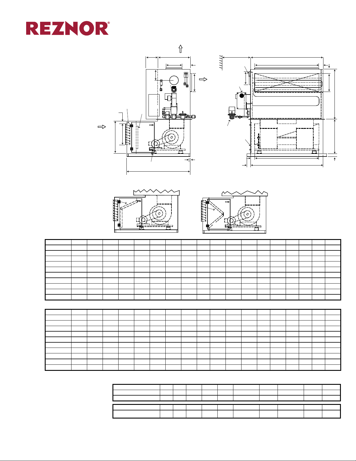
PCDV Basic Vertical Unit (“L” Conguration)
Burner Section and Blower Section only
±1/8” (3mm)
OUTDOOR AIR
DAMPER
3”
(76mm)
OUTDOOR
FLOW
FILTER
AIR
M
D
MOTOR
FILTER
MOTOR
SPRING
ISOLATOR
P
T
E
SUPPLY AIR
OPTION
F
PUFF
DOOR
N
MINIMUM
L
G
C
L
K
SUPPLY AIR
OPTION
CONNECTION
Z
CLEARANCE
GRAVITY VENT
CONNECTION
POWER
BURNER
GAS
HINGED DOOR
ACCESS
HANDLE
W
C/W
U
4”
(102mm)
C
H
COMBUSTION PATH
HEAT EXCHANGER
SECTION
BLOWER/FILTER
SECTION
BLOWERS
H
C
U
U
K
B
A
V
END VIEWSIDE VIEW
V-BANK
FILTER
MOTOR
Dimensions ±1/8”
Sizes A B C D E F G H K L M N P T U V W Z
20/25 34 47 32 32 64 18 7 23 18 32 19 56 15 10 4 1/2 3 8 1 3/8
35/40 34 47 48 32 64 18 7 39 18 32 19 56 15 10 4 1/2 3 8 1 3/8
45/55 38 55 60 36 70 18 9 51 20 36 23 56 10 12 4 1/2 3 10 1 3/8
65/75 38 55 80 36 70 18 9 71 20 36 23 56 10 12 4 1/2 3 10 1 3/8
85/100 50 62 80 48 82 18 15 71 20 48 35 56 10 12 4 1/2 4 12 1 9/16
125/150/175 56 72 100 54 90 24 15 91 30 54 41 56 10 12 4 1/2 4 12 1 9/16
200/250 62 72 120 60 95 30 15 111 32 60 47 56 10 12 1/2 4 1/2 4 12 1 9/16
275/300/325 67 84 140 65 96 30 17 1/2 131 32 65 52 56 - 14 4 1/2 4 14 1 9/16
350/400 72 100 160 70 107 30 20 148 32 70 57 56 - 11 1/2 6 6 16 2
500/600 82 141 180 80 117 48 16 168 32 80 67 56 - 14 6 6 18 2
Dimensions (±3mm)
Sizes A B C D E F G H K L M N P T U V W Z
20/25 (864) (1,194) (813) (813) (1,626) (457) (178) (584) (457) (813) (483) (1,422) (381) (254) (114) (76) (203) (35)
35/40 (864) (1,194) (1,219) (813) (1,626) (457) (178) (991) (457) (813) (483) (1,422) (381) (254) (114) (76) (203) (35)
45/55 (965) (1,397) (1,524) (914) (1,778) (457) (229) (1,295) (508) (914) (584) (1,422) (254) (305) (114) (76) (254) (35)
65/75 (965) (1,397) (2,032) (914) (1,778) (457) (229) (1,803) (508) (914) (584) (1,422) (254) (305) (114) (76) (254) (35)
85/100 (1,270) (1,575) (2,032) (1,219) (2,083) (457) (381) (1,803) (508) (1,219) (889) (1,422) (254) (305) (114) (102) (305) (40)
125/150/175 (1,422) (1,829) (2,540) (1,372) (2,286) (610) (381) (2,311) (762) (1,372) (1,041) (1,422) (254) (305) (114) (102) (305) (40)
200/250 (1,575) (1,829) (3,048) (1,524) (2,413) (762) (381) (2,819) (813) (1,524) (1,194) (1,422) (254) (318) (114) (102) (305) (40)
275/300/325 (1,702) (2,134) (3,556) (1,651) (2,438) (762) (445) (3,327) (813) (1,651) (1,321) (1,422) - (356) (114) (102) (356)
(40)
350/400 (1,829) (2,540) (4,064) (1,778) (2,718) (762) (508) (3,759) (813) (1,778) (1,448) (1,422) - (292) (152) (152) (406) (51)
500/600 (2,083) (3,581) (4,572) (2,032) (2,972) (1,219) (406) (4,267) (813) (2,032) (1,702) (1,422) - (356) (152) (152) (457) (51)
20/25 35/40 45/55 65/75 85/100 125/150/175 200/250 275/300/325 350/400 500/600
Base Weight Lbs. 1,510 1,900 2,375 3,055 3,810 5,335 6,700 8,590 10,280 15,170
with V-Bank Filter Rack 1,675 1,980 2,480 3,220 3,990 5,390 6,765 8,655 10,365 15,295
Base Weight (kg) (685) (862) (1077) (1386) (1728) (2420) (3039) (3896) (4663) (6881)
with V-Bank Filter Rack (760) (898) (1125) (1461) (1810) (2445) (3069) (3926) (4702) (6938)
Form S-PCD Page 13
Page 14
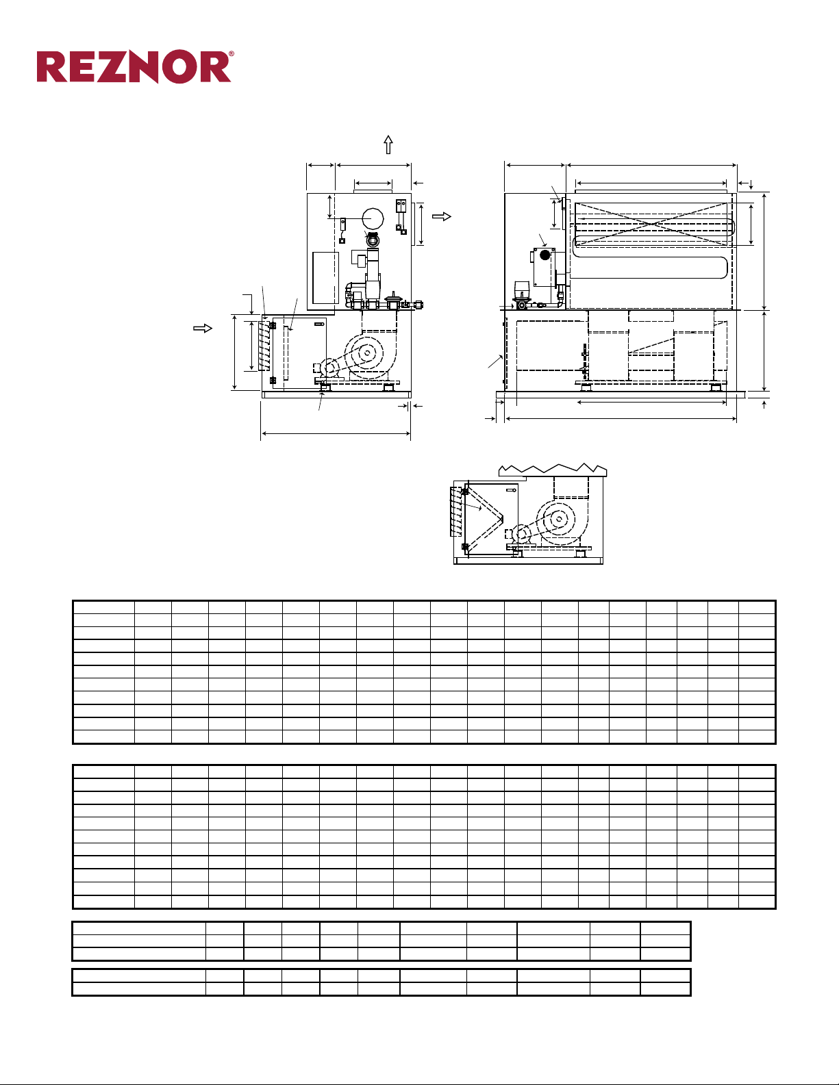
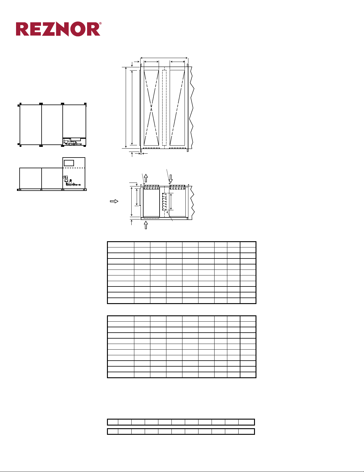
HPCDV Basic Vertical Unit (“L” Conguration)
Burner Section and Blower Section only
±1/8” (3mm)
OUTDOOR AIR
DAMPER
3”
FILTER
M
MOTOR
SPRING
ISOLATOR
OUTDOOR
AIR
FLOW
(76mm)
D
DIMENSIONS (cont’d)
SUPPLY AIR
OPTION
P
T
E
PUFF
DOOR
L
F
G
C
L
K
SUPPLY AIR
OPTION
GAS
CONNECTION
HINGED DOOR
C/W
ACCESS
Z
HANDLE
(102mm)
GRAVITY VENT
CONNECTION
POWER
BURNER
U
4”
Page Number _______ of ______
N
W
C
H
COMBUSTION PATH
HEAT EXCHANGER
SECTION
BLOWER/FILTER
SECTION
BLOWERS
H
C
U
U
K
B
A
V
END VIEWSIDE VIEW
V-BANK
FILTER
MOTOR
Dimensions ±1/8”
Sizes A B C D E F G H K L M N P T U V W Z
20/25 40 47 62 38 64 18 10 23 18 38 19 56 15 10 4 1/2 3 8 1 3/8
35/40 40 47 78 38 64 18 10 39 18 38 19 56 15 10 4 1/2 3 8 1 3/8
45/55 44 55 90 42 70 18 12 51 20 42 23 56 10 12 4 1/2 3 10 1 3/8
65/75 44 55 110 42 70 18 12 71 20 42 23 56 10 12 4 1/2 3 10 1 3/8
85/100 56 62 110 54 82 18 18 71 20 54 35 56 10 12 4 1/2 4 12 1 9/16
125/150/175 62 72 130 60 90 24 18 91 30 60 41 56 10 12 4 1/2 4 12 1 9/16
200/250 68 72 150 66 95 30 18 111 32 66 47 56 10 12 1/2 4 1/2 4 12 1 9/16
275/300/325 73 84 170 71 96 30 20 1/2 131 32 71 52 56 - 14 4 1/2 4 14 1 9/16
350/400 78 100 190 76 107 30 23 148 32 76 57 56 - 11 1/2 6 6 16 2
500/600 88 141 210 86 117 48 19 168 32 86 67 56 - 14 6 6 18 2
Dimensions (±3mm)
Sizes A B C D E F G H K L M N P T U V W Z
20/25 (1,016) (1,194) (1,575) (965) (1,626) (457) (254) (584) (457) (965) (483) (1,422) (381) (254) (114) (76) (203) (35)
35/40 (1,016) (1,194) (1,981) (965) (1,626) (457) (254) (991) (457) (965) (483) (1,422) (381) (254) (114) (76) (203) (35)
45/55 (1,118) (1,397) (2,286) (1,067) (1,778) (457) (305) (1,295) (508) (1,067) (584) (1,422) (254) (305) (114) (76) (254) (35)
65/75 (1,118) (1,397) (2,794) (1,067) (1,778) (457) (305) (1,803) (508) (1,067) (584) (1,422) (254) (305) (114) (76) (254) (35)
85/100 (1,422) (1,575) (2,794) (1,372) (2,083) (457) (457) (1,803) (508) (1,372) (889) (1,422) (254) (305) (114) (102) (305) (40)
125/150/175 (1,575) (1,829) (3,302) (1,524) (2,286) (610) (457) (2,311) (762) (1,524) (1,041) (1,422) (254) (305) (114) (102) (305) (40)
200/250 (1,727) (1,829) (3,810) (1,676) (2,413) (762) (457) (2,819) (813) (1,676) (1,194) (1,422) (254) (318) (114) (102) (305) (40)
275/300/325 (1,854) (2,134) (4,318) (1,803) (2,438) (762) (521) (3,327) (813) (1,803) (1,321) (1,422) - (356) (114) (102) (356)
(40)
350/400 (1,981) (2,540) (4,826) (1,930) (2,718) (762) (584) (3,759) (813) (1,930) (1,448) (1,422) - (292) (152) (152) (406) (51)
500/600 (2,235) (3,581) (5,334) (2,184) (2,972) (1,219) (483) (4,267) (813) (2,184) (1,702) (1,422) - (356) (152) (152) (457) (51)
20/25 35/40 45/55 65/75 85/100 125/150/175 200/250 275/300/325 350/400 500/600
Base Weight Lbs. 1,770 2,265 2,865 3,565 4,245 5,880 7,365 9,275 11,070 16,025
with V-Bank Filter Rack 2,020 2,390 3,045 3,805 4,495 5,950 7,455 9,350 11,160 16,190
Base Weight (kg) (803) (1027) (1300) (1617) (1926) (2667) (3341) (4207) (5021) (7269)
with V-Bank Filter Rack (916) (1084) (1381) (1726) (2039) (2699) (3382) (4241) (5062) (7344)
Form S-PCD Page 14
Page 15
Page Number _______ of ______
DIMENSIONS (cont’d)
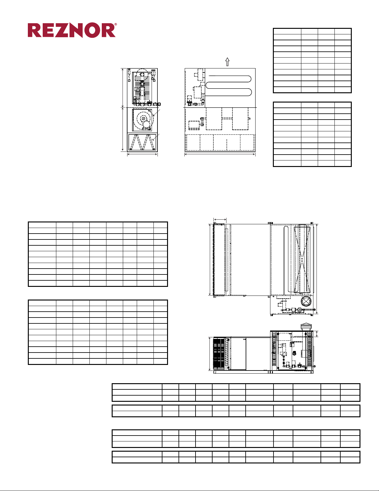
HPCDV Basic Vertical Unit (“I” Conguration)
Burner Section and Blower Section only (Requires Mounting Base)
±1/8” (3mm)
B
BLOWER
A
FILTER
C
MOTOR
AIR
FLOW
COMBUSTION PATH
HEAT EXCHANGER
SECTION
BLOWER BLOWER
BLOWER/FILTER
SECTION
D
END VIEWSIDE VIEW
Dimensions ±1/8”
Sizes A B C
20/25 42 38 62
35/40 48 38 78
45/55 54 42 90
65/75 60 42 110
85/100 60 54 110
125/150/175 70 60 132
200/250 100 66 156
275/300/325 100 71 176
350/400 100 86 196
500/600 120 86 216
Dimensions (±3mm)
Sizes A B C
20/25 (1,067) (965) (1,575)
35/40 (1,219) (965) (1,981)
45/55 (1,372) (1,067) (2,286)
65/75 (1,524) (1,067) (2,794)
85/100 (1,524) (1,372) (2,794)
125/150/175 (1,778) (1,524) (3,353)
200/250 (2,540) (1,676) (3,962)
275/300/325 (2,540) (1,803) (4,470)
350/400 (2,540) (2,184) (4,978)
500/600 (3,048) (2,184) (5,486)
PCDH/HPCDH (Outdoor Unit)
Outdoor units include a weatherhousing that covers the control section. Weatherhousing roof slopes away from controls on sizes 125 and larger.
Outdoor unit shown here with optional Louvered Inlet Air Hood.
Vertical (“L” Conguration) outdoor units have the same louvered inlet hood sizes. The weatherhousing conforms to the size of the controls section.
±1/8” (3mm)
Dimensions ±1/8”
Sizes A
20/25 32 38 32 62 10 62 18
35/40 32 38 48 78 10 78 18
45/55 36 42 60 90 10 90 18
65/75 36 42 80 110 10 110 18
85/100 48 54 80 110 10 110 12
125/150/175 54 60 100 132 24 132 12
200/250 60 66 120 156 24 156 12
275/300/325 65 71 140 176 24 176 12
350/400 70 76 160 196 24 196 -
500/600 80 86 180 216 24 216 -
Dimensions (±3mm)
Sizes A
20/25 (813) (965) (813) (1,575) (254) (1,575) (457)
35/40 (813) (965) (1,219) (1,981) (254) (1,981) (457)
45/55 (914) (1,067) (1,524) (2,286) (254) (2,286) (457)
65/75 (914) (1,067) (2,032) (2,794) (254) (2,794) (457)
85/100 (1,219) (1,372) (2,032) (2,794) (254) (2,794) (305)
125/150/175 (1,372) (1,524) (2,540) (3,353) (610) (3,353) (305)
200/250 (1,524) (1,676) (3,048) (3,962) (610) (3,962) (305)
275/300/325 (1,651) (1,803) (3,556) (4,470) (610) (4,470) (305)
350/400 (1,778) (1,930) (4,064) (4,978) (610) (4,978) -
500/600 (2,032) (2,184) (4,572) (5,486) (610) (5,486) -
Note: A1 and B1 are dimensions for Model PCDH. A2 and B2 are dimensions for
Model HPCDH
1
2
1
A
B
1
2
A
B
2
B
C D E
1
2
B
C D E
Weight PCDH - lbs. (kg)
20/25 35/40 45/55 65/75 85/100 125/150/175 200/250 275/300/325 350/400 500/600
Base Unit 1,750 2,140 2,645 3,325 4,110 5,685 7,125 9,090 10,930 15,845
with V-Bank Filter Rack 1,915 2,220 2,750 3,490 4,290 5,740 7,190 9,155 11,015 15,970
Base Unit (794) (971) (1200) (1508) (1864) (2579) (3232) (4123) (4958) (7187)
with V-Bank Filter Rack (869) (1007) (1247) (1583) (1946) (2604) (3261) (4153) (4996) (7244)
LOUVERED INLET
HOOD SECTION
C
B
A
D
E
HWeight PCDH - lbs. (kg)
20/25 35/40 45/55 65/75 85/100 125/150/175 200/250 275/300/325 350/400 500/600
Base Weight Lbs. 2,010 2,505 3,135 3,835 2,848 6,230 7,790 9,775 11,720 16,700
with V-Bank Filter Rack 2,260 2,630 3,315 4,075 3,098 6,300 7,880 9,850 11,810 16,865
Base Weight (kg) (912) (1136) (1422) (1740) (1292) (2826) (3534) (4434) (5316) (7575)
with V-Bank Filter Rack (1025) (1193) (1504) (1848) (1405) (2858) (3574) (4468) (5357) (7650)
Form S-PCD Page 15
Page 16

SIDE VIEW
DIMENSIONS (cont’d)
Page Number _______ of ______
PCD Accessories
Blower/Filter/Coil Section
±1/8” (3mm)
Displayed on the following pages are accessory modules for Model PCD.
The illustration on the left will show the relative location and size of the module. For example, this page
shows the Blower/Filter/Coil Section which replaces
the Blower/Filter section. Other optional sections will
be shown attached to the downstream air side of the
Blower Section
Dimensional drawings and a dimension table in inches (mm) are also shown.
BLOWER/
FILTER/
COIL
SECTION
HEAT
EXCHANGER
SECTION
BLOWER/
FILTER/
COIL
SECTION
HEAT
EXCHANGER
SECTION
PCDH Conguration HPCDH Conguration
CONTROL
BOX
CONTROL
BOX
(102mm)
OUTDOOR
AIR
FLOW
B
TYP. 4”
(76mm)
C
F
K
D
3”
E
FILTER
BLOWER/FILTER/COIL
H
J
HINGED DOOR
ACCESS
HANDLE
TOP VIEW
OUTDOOR AIR
DAMPER
G
DX
DRAIN
COIL
PAN
SECTION
A
C/W
MOTOR
SPRING
ISOLATOR
BLOWER
Dimensions ±1/8”
Sizes A
A
B
B
C
C
D
2
D
E F G
1
2
1
G
H
2
H
J K
1
2
1
2
1
2
1
20/25 82 67 32 62 32 38 23 53 19 3 23 29 22 47 1 3/8 4 1/2
35/40 90 70 48 78 32 38 39 69 19 3 23 29 23 63 1 3/8 4 1/2
45/55 97 77 60 90 36 42 51 81 23 3 27 33 45 75 1 3/8 4 1/2
65/75 92 72 80 110 36 42 71 101 23 3 27 33 65 95 1 3/8 4 1/2
85/100 98 80 80 110 48 54 71 101 35 4 39 44 65 95 1 9/16 4 1/2
125/150/175 102 87 100 132 54 60 91 123 41 4 45 51 85 117 1 9/16 4 1/2
200/250 100 90 120 156 60 66 111 147 47 4 51 57 102 141 1 9/16 4 1/2
275/300/325 102 95 140 176 65 71 131 167 52 4 56 62 125 161 1 9/16 4 1/2
350/400 102 98 160 196 70 76 148 184 57 6 61 67 145 181 2 6
500/600 108 102 180 220 80 86 168 204 67 6 71 77 165 201 2 6
Dimensions (±3mm)
Sizes A
A
B
B
C
C
D
2
D
E F G
1
2
1
G
H
2
H
J K
1
2
1
2
1
2
1
20/25 (2,083) (1,702) (813) (1,575) (813) (965) (584) (1,346) (483) (76) (584) (737) (559) (1,194) (35) (114)
35/40 (2,286) (1,778) (1,219) (1,981) (813) (965) (991) (1,753) (483) (76) (584) (737) (584) (1,600) (35) (114)
45/55 (2,464) (1,956) (1,524) (2,286) (914) (1,067) (1,295) (2,057) (584) (76) (686) (838) (1,143) (1,905) (35) (114)
65/75 (2,337) (1,829) (2,032) (2,794) (914) (1,067) (1,803) (2,565) (584) (76) (686) (838) (1,651) (2,413) (35) (114)
85/100 (2,489) (2,032) (2,032) (2,794) (1,219) (1,372) (1,803) (2,565) (889) (102) (991) (1,118) (1,651) (2,413) (40) (114)
125/150/175 (2,591) (2,210) (2,540) (3,353) (1,372) (1,524) (2,311) (3,124) (1,041) (102) (1,143) (1,295) (2,159) (2,972) (40) (114)
200/250 (2,540) (2,286) (3,048) (3,962) (1,524) (1,676) (2,819) (3,734) (1,194) (102) (1,295) (1,448) (2,591) (3,581) (40) (114)
275/300/325 (2,591) (2,413) (3,556) (4,470) (1,651) (1,803) (3,327) (4,242) (1,321) (102) (1,422) (1,575) (3,175) (4,089) (40) (114)
350/400 (2,591) (2,489) (4,064) (4,978) (1,778) (1,930) (3,759) (4,674) (1,448) (152) (1,549) (1,702) (3,683) (4,597) (51) (152)
500/600 (2,743) (2,591) (4,572) (5,588) (2,032) (2,184) (4,267) (5,182) (1,702) (152) (1,803) (1,956) (4,191) (5,105) (51) (152)
Note: A1, B1, etc. are dimensions for Model PCDH. A2, B2, etc. are dimensions for Model HPCDH
Form S-PCD Page 16
Page 17
HPCDV Accessories (“I” Conguration) (cont’d)
AIR FLOW
Cooling Coil Cabinet (Indoor/Outdoor)
±1/8” (3mm)
DISCHARGE AIR
SECTION
COOLING COIL
SECTION
BURNER
SECTION
BLOWER/FILTER
SECTION
DIMENSIONS (cont’d)
B
A
C
FLOW
END VIEWSIDE VIEW
AIR
Page Number _______ of ______
Dimensions ±1/8”
Sizes A B C
20/25 42 38 62
35/40 48 38 78
45/55 54 42 90
65/75 60 42 110
85/100 60 54 110
125/150/175 70 60 132
200/250 100 66 156
275/300/325 100 71 176
350/400 100 86 196
500/600 120 86 216
Dimensions (±3mm)
Sizes A B C
20/25 (1,067) (965) (1,575)
35/40 (1,219) (965) (1,981)
45/55 (1,372) (1,067) (2,286)
65/75 (1,524) (1,067) (2,794)
85/100 (1,524) (1,372) (2,794)
125/150/175 (1,778) (1,524) (3,353)
200/250 (2,540) (1,676) (3,962)
275/300/325 (2,540) (1,803) (4,470)
350/400 (2,540) (2,184) (4,978)
500/600 (3,048) (2,184) (5,486)
HPCDH Accessories (cont’d)
Mixing Box
±1/8” (3mm)
BOX
BLOWER/
FILTER
SECTION
HEAT
EXCHANGER
SECTION
CONTROL
BOX
MIXING
SECTION
INLET AIR
MOUNTING BASE
TYP. 4”
(102mm)
(76mm)
FLOW
B
DAMPER
3”
C
MIXING BOX
G
D
G
TOP VIEW
E
SECTION
A
F
AIR FLOW
OPTION
DAMPER
Dimensions ±1/8”
Sizes A B C D E F G H
20/25 27 62 38 53 19 3 4 1/2 18
35/40 27 78 38 69 19 3 4 1/2 18
45/55 29 90 42 81 23 3 4 1/2 20
65/75 29 110 42 101 23 3 4 1/2 20
85/100 29 110 54 101 35 4 4 1/2 20
125/150/175 39 132 60 123 41 4 4 1/2 30
200/250 41 156 66 147 47 4 4 1/2 32
275/300/325 41 176 71 167 52 4 4 1/2 32
350/400 44 196 76 184 57 6 6 32
500/600 44 216 86 204 67 6 6 32
Dimensions (±3mm)
Sizes A B C D E F G H
20/25 (686) (1,575) (965) (1,346) (483) (76) (114) (457)
35/40 (686) (1,981) (965) (1,753) (483) (76) (114) (457)
45/55 (737) (2,286) (1,067) (2,057) (584) (76) (114) (508)
65/75 (737) (2,794) (1,067) (2,565) (584) (76) (114) (508)
85/100 (737) (2,794) (1,372) (2,565) (889) (102) (114) (508)
125/150/175 (991) (3,353) (1,524) (3,124) (1,041) (102) (114) (762)
200/250 (1,041) (3,962) (1,676) (3,734) (1,194) (102) (114) (813)
275/300/325 (1,041) (4,470) (1,803) (4,242) (1,321) (102) (114) (813)
350/400 (1,118) (4,978) (1,930) (4,674) (1,448) (152) (152) (813)
500/600 (1,118) (5,486) (2,184) (5,182) (1,702) (152) (152) (813)
H
AIR FLOW
OPTION
SIDE VIEW
Weight - Mixing Box only (Add to base unit weight)
lbs 200 260 335 420 495 710 935 1055 1250 1555
(kg) (91) (118) (152) (191) (225) (322) (424) (479) (567) (705)
Form S-PCD Page 17
Page 18

PCDH/PCDV Accessories (cont’d)
Mixing Box
±1/8” (3mm)
BOX
BLOWER/
FILTER
SECTION
OR
BLOWER/
FILTER/
COIL
SECTION
EXCHANGER
SECTION
CONTROL
BOX
CONTROL
BOX
HEAT
MIXING
SECTION
TYP. 4”
(102mm)
(76mm)
AIR FLOW
OPTION
DIMENSIONS (cont’d)
MIXING BOX
SECTION
A
G
B
D
G
H
TOP VIEW
DAMPER
3”
C
F
E
SIDE VIEW
BURNER
SECTION
AIR FLOW
OPTION
AIR FLOW
OPTION
DAMPER
Page Number _______ of ______
Dimensions ±1/8”
Sizes A B C D E F G H
20/25 27 32 32 23 19 3 4 1/2 18
35/40 27 48 32 39 19 3 4 1/2 18
45/55 29 60 36 51 23 3 4 1/2 20
65/75 29 80 36 71 23 3 4 1/2 20
85/100 29 80 48 71 35 4 4 1/2 20
125/150/175 39 100 54 91 41 4 4 1/2 30
200/250 41 120 60 111 47 4 4 1/2 32
275/300/325 41 140 65 131 52 4 4 1/2 32
350/400 44 160 70 148 57 6 6 32
500/600 44 180 80 168 67 6 6 32
Dimensions (±3mm)
Sizes A B C D E F G H
20/25 (686) (813) (813) (584) (483) (76) (114) (457)
35/40 (686) (1,219) (813) (991) (483) (76) (114) (457)
45/55 (737) (1,524) (914) (1,295) (584) (76) (114) (508)
65/75 (737) (2,032) (914) (1,803) (584) (76) (114) (508)
85/100 (737) (2,032) (1,219) (1,803) (889) (102) (114) (508)
125/150/175 (991) (2,540) (1,372) (2,311) (1,041) (102) (114) (762)
200/250 (1,041) (3,048) (1,524) (2,819) (1,194) (102) (114) (813)
275/300/325 (1,041) (3,556) (1,651) (3,327) (1,321) (102) (114) (813)
350/400 (1,118) (4,064) (1,778) (3,759) (1,448) (152) (152) (813)
500/600 (1,118) (4,572) (2,032) (4,267) (1,702) (152) (152) (813)
Weight - Mixing Box only (Add to base unit weight)
lbs 200 260 335 420 495 710 935 1055 1250 1555
(kg) (91) (118) (152) (191) (225) (322) (424) (479) (567) (705)
MIXING BOX
SECTION
BLOWER/FILTER
SECTION
PCDH Accessories (cont’d)
Mixing Box w/Relief (Indoor)
±1/8” (3mm)
BOX
BLOWER/
FILTER
SECTION
HEAT
EXCHANGER
SECTION
CONTROL
BOX
MIXING
w/RELIEF
SECTION
(76mm)
RETURN AIR
FLOW
D
B
TYP. 4”
(102mm)
RELIEF AIR
DAMPER
3”
C
F
BLOWER/FILTER
SECTION
MIXING BOX w/RELIEF
G
G
H
RELIEF
AIR FLOW
E
RETURN AIR
OPTION
SECTION
TOP VIEW
FRESH AIR
DAMPER
SIDE VIEW
A
EE
OUTDOOR
AIR FLOW
E
RETURN AIR
DAMPER
Dimensions ±1/8”
Sizes A B C D E F G H
20/25 27 32 32 23 19 3 4 1/2 1 3/8
35/40 27 48 32 39 19 3 4 1/2 1 3/8
45/55 29 60 36 51 23 3 4 1/2 1 3/8
65/75 29 80 36 71 23 3 4 1/2 1 3/8
85/100 29 80 48 71 35 4 4 1/2 1 9/16
125/150/175 39 100 54 91 41 4 4 1/2 1 9/16
200/250 41 120 60 111 47 4 4 1/2 1 9/16
275/300/325 41 140 65 131 52 4 4 1/2 1 9/16
350/400 44 160 70 148 57 6 6 2
500/600 44 180 80 168 67 6 6 2
Dimensions (±3mm)
Sizes A B C D E F G H
20/25 (686) (813) (813) (584) (483) (76) (114) (35)
35/40 (686) (1,219) (813) (991) (483) (76) (114) (35)
45/55 (737) (1,524) (914) (1,295) (584) (76) (114) (35)
65/75 (737) (2,032) (914) (1,803) (584) (76) (114) (35)
85/100 (737) (2,032) (1,219) (1,803) (889) (102) (114) (40)
125/150/175 (991) (2,540) (1,372) (2,311) (1,041) (102) (114) (40)
200/250 (1,041) (3,048) (1,524) (2,819) (1,194) (102) (114) (40)
275/300/325 (1,041) (3,556) (1,651) (3,327) (1,321) (102) (114) (40)
350/400 (1,118) (4,064) (1,778) (3,759) (1,448) (152) (152) (51)
500/600 (1,118) (4,572) (2,032) (4,267) (1,702) (152) (152) (51)
Weight - Mixing Box only (Add to base unit weight)
lbs 220 290 380 480 580 825 1100 1270 1500 1875
(kg) (100) (132) (172) (218) (263) (374) (499) (576) (680) (851)
Form S-PCD Page 18
Page 19

DIMENSIONS (cont’d)
Page Number _______ of ______
PCDH Accessories (cont’d)
Mixing Box w/Relief (Outdoor)
±1/8” (3mm)
RELIEF
AIR HOOD
RETURN
AIR
BLOWER
SECTION
MIXING
w/RELIEF
SECTION
FRESH
AIR HOOD
BOX
BLOWER/
FILTER
SECTION
EXCHANGER
SECTION
CONTROL
BOX
HEAT
TYP. 4”
(102mm)
RETURN AIR
OPTION
RELIEF
HOOD
B
INLET
HOOD
(102mm)
C
H
4”
E
MIXING BOX
w/RELIEF
SECTION
A
RELIEF
AIR FLOW
D
(DxE)
RETURN AIR DAMPER
D
OUTDOOR
AIR FLOW
TOP VIEW
SIDE VIEW
G
F
F
G
Dimensions ±1/8”
Sizes A B C D E F G H
20/25 29 32 32 20 24 4 1/2 28 3
35/40 39 48 32 30 24 4 1/2 28 3
45/55 45 60 36 36 28 4 1/2 31 3
65/75 59 80 36 50 28 4 1/2 31 3
85/100 51 80 48 42 40 4 1/2 39 4
125/150/175 69 100 54 60 46 4 1/2 53 4
200/250 73 120 60 64 52 4 1/2 59 4
275/300/325 79 140 65 70 57 4 1/2 64 4
350/400 90 160 70 78 62 6 69 6
500/600 102 180 80 90 72 6 79 6
Dimensions (±3mm)
Sizes A B C D E F G H
20/25 (737) (813) (813) (508) (610) (114) (711) (76)
35/40 (991) (1,219) (813) (762) (610) (114) (711) (76)
45/55 (1,143) (1,524) (914) (914) (711) (114) (787) (76)
65/75 (1,499) (2,032) (914) (1,270) (711) (114) (787) (76)
85/100 (1,295) (2,032) (1,219) (1,067) (1,016) (114) (991) (102)
125/150/175 (1,753) (2,540) (1,372) (1,524) (1,168) (114) (1,346) (102)
200/250 (1,854) (3,048) (1,524) (1,626) (1,321) (114) (1,499) (102)
275/300/325 (2,007) (3,556) (1,651) (1,778) (1,448) (114) (1,626) (102)
350/400 (2,286) (4,064) (1,778) (1,981) (1,575) (152) (1,753) (152)
500/600 (2,591) (4,572) (2,032) (2,286) (1,829) (152) (2,007) (152)
Weight - Mixing Box only (Add to base unit weight)
lbs 220 290 380 480 580 825 1100 1270 1500 1875
(kg) (100) (132) (172) (218) (263) (374) (499) (576) (680) (851)
Form S-PCD Page 19
Page 20
DIMENSIONS (cont’d)
Page Number _______ of ______
HPCDH Accessories (cont’d)
Mixing Box w/Relief
±1/8” (3mm)
BOX
BLOWER/
FILTER
SECTION
HEAT
EXCHANGER
SECTION
CONTROL
BOX
MIXING
w/RELIEF
SECTION
(102mm)
(76mm)
RETURN AIR
FLOW
B
TYP. 4”
RELIEF AIR
DAMPER
3”
C
G
G
D
E
MIXING BOX w/RELIEF
SECTION
A
EE
TOP VIEW
H
FRESH AIR
DAMPER
RELIEF
AIR FLOW
OUTDOOR
AIR FLOW
E
F
RETURN AIR
OPTION
SIDE VIEW
RETURN AIR
DAMPER
Dimensions ±1/8”
Sizes A B C D E F G H
20/25 60 62 38 53 19 3 4 1/2 1 3/8
35/40 60 78 38 69 19 3 4 1/2 1 3/8
45/55 69 90 42 81 23 3 4 1/2 1 3/8
65/75 69 110 42 101 23 3 4 1/2 1 3/8
85/100 93 110 54 101 35 4 4 1/2 1 9/16
125/150/175 105 132 60 123 41 4 4 1/2 1 9/16
200/250 117 156 66 147 47 4 4 1/2 1 9/16
275/300/325 127 176 71 167 52 4 4 1/2 1 9/16
350/400 137 196 86 184 57 6 6 2
500/600 151 216 86 204 67 6 6 2
Dimensions (±3mm)
Sizes A B C D E F G H
20/25 (1,524) (1,575) (965) (1,346) (483) (76) (114) (35)
35/40 (1,524) (1,981) (965) (1,753) (483) (76) (114) (35)
45/55 (1,753) (2,286) (1,067) (2,057) (584) (76) (114) (35)
65/75 (1,753) (2,794) (1,067) (2,565) (584) (76) (114) (35)
85/100 (2,362) (2,794) (1,372) (2,565) (889) (102) (114) (40)
125/150/175 (2,667) (3,353) (1,524) (3,124) (1,041) (102) (114) (40)
200/250 (2,972) (3,962) (1,676) (3,734) (1,194) (102) (114) (40)
275/300/325 (3,226) (4,470) (1,803) (4,242) (1,321) (102) (114) (40)
350/400 (3,480) (4,978) (2,184) (4,674) (1,448) (152) (152) (51)
500/600 (3,835) (5,486) (2,184) (5,182) (1,702) (152) (152) (51)
Form S-PCD Page 20
Weight - Mixing Box only (Add to base unit weight)
lbs 390 500 505 785 880 1185 1550 1705 1940 2385
(kg) (177) (227) (229) (356) (399) (538) (703) (773) (880) (1082)
Page 21

HPCDV Accessories (“I” Conguration) (cont’d)
A
Screened Mounting Base (Indoor)
±1/8” (3mm)
DISCHARGE AIR
SECTION
BURNER
SECTION
BLOWER/FILTER
SECTION
INLET AIR
MOUNTING BASE
A
DIMENSIONS (cont’d)
AIR
FLOW
B
C
END VIEWSIDE VIEW
Page Number _______ of ______
Dimensions ±1/8”
Sizes A B C
20/25 24 38 62
35/40 24 38 78
45/55 30 42 90
65/75 30 42 110
85/100 36 54 110
125/150/175 36 60 132
200/250 42 66 156
275/300/325 42 71 176
350/400 48 86 196
500/600 48 86 216
Dimensions (±3mm)
Sizes A B C
20/25 (610) (965) (1,575)
35/40 (610) (965) (1,981)
45/55 (762) (1,067) (2,286)
65/75 (762) (1,067) (2,794)
85/100 (914) (1,372) (2,794)
125/150/175 (914) (1,524) (3,353)
200/250 (1,067) (1,676) (3,962)
275/300/325 (1,067) (1,803) (4,470)
350/400 (1,219) (2,184) (4,978)
500/600 (1,219) (2,184) (5,486)
Screened Discharge Plenum (Indoor)
±1/8” (3mm)
DISCHARGE AIR
BLOWER/FILTER
MOUNTING BASE
SECTION
BURNER
SECTION
SECTION
INLET AIR
Dimensions ±1/8”
Sizes A B C
20/25 24 38 62
35/40 24 38 78
45/55 30 42 90
65/75 30 42 110
85/100 36 54 110
125/150/175 36 60 132
200/250 42 66 156
B
C
275/300/325 42 71 176
350/400 48 86 196
500/600 48 86 216
Dimensions (±3mm)
Sizes A B C
AIR
FLOW
END VIEWSIDE VIEW
20/25 (610) (965) (1,575)
35/40 (610) (965) (1,981)
45/55 (762) (1,067) (2,286)
65/75 (762) (1,067) (2,794)
85/100 (914) (1,372) (2,794)
125/150/175 (914) (1,524) (3,353)
200/250 (1,067) (1,676) (3,962)
275/300/325 (1,067) (1,803) (4,470)
350/400 (1,219) (2,184) (4,978)
500/600 (1,219) (2,184) (5,486)
Form S-PCD Page 21
Page 22

ISOLATOR
DIMENSIONS (cont’d)
Page Number _______ of ______
PCDH Accessories (cont’d)
Return Air Blower and Mixing Box w/Relief
±1/8” (3mm)
RETURN
AIR
BLOWER
SECTION
MIXING
w/RELIEF
SECTION
BOX
BLOWER/
FILTER
SECTION
HEAT
EXCHANGER
SECTION
CONTROL
BOX
Dimensions ±1/8”
Sizes A B C D E F G
20/25 61 32 32 23 19 3 4 1/2
35/40 68 48 32 39 19 3 4 1/2
45/55 72 60 36 51 23 3 4 1/2
65/75 75 80 36 71 23 3 4 1/2
85/100 100 80 48 71 35 4 4 1/2
125/150/175 109 100 54 91 41 4 4 1/2
200/250 117 120 60 111 47 4 4 1/2
275/300/325 122 140 65 131 52 4 4 1/2
350/400 127 160 70 148 57 6 6
500/600 137 180 80 168 67 6 6
Dimensions (±3mm)
Sizes A B C D E F G
20/25 (1,549) (813) (813) (584) (483) (76) (114)
35/40 (1,727) (1,219) (813) (991) (483) (76) (114)
45/55 (1,829) (1,524) (914) (1,295) (584) (76) (114)
65/75 (1,905) (2,032) (914) (1,803) (584) (76) (114)
85/100 (2,540) (2,032) (1,219) (1,803) (889) (102) (114)
125/150/175 (2,769) (2,540) (1,372) (2,311) (1,041) (102) (114)
200/250 (2,972) (3,048) (1,524) (2,819) (1,194) (102) (114)
275/300/325 (3,099) (3,556) (1,651) (3,327) (1,321) (102) (114)
350/400 (3,226) (4,064) (1,778) (3,759) (1,448) (152) (152)
500/600 (3,480) (4,572) (2,032) (4,267) (1,702) (152) (152)
(102mm)
RETURN AIR
OPTION
B
TYP. 4”
(76mm)
C
F
RETURN AIR BLOWER
G
G
D
3”
E
RETURN AIR
OPTION
SECTION
A
E
MOTOR
TOP VIEW
SIDE VIEW
BLOWER
HINGED DOOR
ACCESS c/w
HANDLE (TYP)
SPRING
Form S-PCD Page 22
Page 23

DIMENSIONS (cont’d)
Page Number _______ of ______
HPCDH Accessories (cont’d)
Return Air Blower and Mixing Box w/Relief
±1/8” (3mm)
RETURN
AIR
BLOWER
SECTION
MIXING
w/RELIEF
SECTION
BOX
BLOWER/
FILTER
SECTION
HEAT
EXCHANGER
SECTION
CONTROL
BOX
(102mm)
RETURN AIR
OPTION
B
TYP. 4”
(76mm)
F
RETURN AIR BLOWER
SECTION
A
E
G
G
D
BLOWERS
MOTOR
TOP VIEW
3”
E
C
RETURN AIR
OPTION
SIDE VIEW
HINGED DOOR
ACCESS c/w
HANDLE (TYP)
SPRING
ISOLATOR
Dimensions ±1/8”
Sizes A B C D E F G
20/25 61 62 38 53 19 3 4 1/2
35/40 68 78 38 69 19 3 4 1/2
45/55 72 90 42 81 23 3 4 1/2
65/75 75 110 42 101 23 3 4 1/2
85/100 100 110 54 101 35 4 4 1/2
125/150/175 109 132 60 123 41 4 4 1/2
200/250 117 156 66 147 47 4 4 1/2
275/300/325 122 176 71 167 52 4 4 1/2
350/400 127 196 86 184 57 6 6
500/600 137 216 86 204 67 6 6
Dimensions (±3mm)
Sizes A B C D E F G
20/25 (1,549) (1,575) (965) (1,346) (483) (76) (114)
35/40 (1,727) (1,981) (965) (1,753) (483) (76) (114)
45/55 (1,829) (2,286) (1,067) (2,057) (584) (76) (114)
65/75 (1,905) (2,794) (1,067) (2,565) (584) (76) (114)
85/100 (2,540) (2,794) (1,372) (2,565) (889) (102) (114)
125/150/175 (2,769) (3,353) (1,524) (3,124) (1,041) (102) (114)
200/250 (2,972) (3,962) (1,676) (3,734) (1,194) (102) (114)
275/300/325 (3,099) (4,470) (1,803) (4,242) (1,321) (102) (114)
350/400 (3,226) (4,978) (2,184) (4,674) (1,448) (152) (152)
500/600 (3,480) (5,486) (2,184) (5,182) (1,702) (152) (152)
Form S-PCD Page 23
Page 24

DIMENSIONS (cont’d)
Page Number _______ of ______
HPCDV Accessories (“I” Conguration) (cont’d)
Insulated Enclosed Mounting Base (Indoor/Outdoor)
±1/8” (3mm)
A
OUTDOOR
AIR FLOW
D D
B
RETURN
AIR FLOW
5”
(127mm)
FLOW
END VIEWSIDE VIEW
AIR
Dimensions ±1/8”
Sizes A B C D E
20/25 30 38 62 20 52
35/40 30 38 78 20 68
45/55 36 42 90 26 80
65/75 36 42 110 26 100
85/100 42 54 110 32 100
125/150/175 48 60 132 38 122
200/250 70 66 156 60 146
275/300/325 70 71 176 60 166
350/400 80 86 196 70 186
500/600 90 86 216 80 206
Dimensions (±3mm)
Sizes A B C D E
20/25 (762) (965) (1,575) (508) (1,321)
35/40 (762) (965) (1,981) (508) (1,727)
45/55 (914) (1,067) (2,286) (660) (2,032)
E
C
5”
65/75 (914) (1,067) (2,794) (660) (2,540)
(127mm)
85/100 (1,067) (1,372) (2,794) (813) (2,540)
125/150/175 (1,219) (1,524) (3,353) (965) (3,099)
200/250 (1,778) (1,676) (3,962) (1,524) (3,708)
275/300/325 (1,778) (1,803) (4,470) (1,524) (4,216)
350/400 (2,032) (2,184) (4,978) (1,778) (4,724)
500/600 (2,286) (2,184) (5,486) (2,032) (5,232)
Tall Insulated Enclosed Mounting Base (Indoor/Outdoor)
±1/8” (3mm)
A
OUTDOOR
AIR FLOW
5”
(127mm)
D D
30”
(762mm)
5”
(127mm)
RETURN
AIR FLOW
30”
(762mm)
B
5”
(127mm)
FLOW
END VIEWSIDE VIEW
AIR
E
Dimensions ±1/8”
Sizes A B C D E
20/25 55 38 62 20 52
35/40 55 38 78 20 68
45/55 61 42 90 26 80
65/75 61 42 110 26 100
85/100 67 54 110 32 100
125/150/175 73 60 132 38 122
200/250 95 66 156 60 146
275/300/325 95 71 176 60 166
350/400 105 86 196 70 186
500/600 115 86 216 80 206
Dimensions (±3mm)
Sizes A B C D E
20/25 (1,397) (965) (1,575) (508) (1,321)
35/40 (1,397) (965) (1,981) (508) (1,727)
45/55 (1,549) (1,067) (2,286) (660) (2,032)
65/75 (1,549) (1,067) (2,794) (660) (2,540)
85/100 (1,702) (1,372) (2,794) (813) (2,540)
5”
(127mm)
C
125/150/175 (1,854) (1,524) (3,353) (965) (3,099)
200/250 (2,413) (1,676) (3,962) (1,524) (3,708)
275/300/325 (2,413) (1,803) (4,470) (1,524) (4,216)
350/400 (2,667) (2,184) (4,978) (1,778) (4,724)
500/600 (2,921) (2,184) (5,486) (2,032) (5,232)
Form S-PCD Page 24
Page 25

DIMENSIONS (cont’d)
Page Number _______ of ______
HPCDV Accessories (“I” Conguration) (cont’d)
Insulated Enclosed Discharge Plenum (Indoor/Outdoor)
±1/8” (3mm)
DISCHARGE AIR
SECTION
BURNER
SECTION
BLOWER/FILTER
SECTION
INLET AIR
MOUNTING BASE
B
A
D
5”
(127mm)
SUPPLY
AIR FLOW
Dimensions ±1/8”
Sizes A B C D E
20/25 30 38 62 20 52
35/40 30 38 78 20 68
45/55 36 42 90 26 80
65/75 36 42 110 26 100
85/100 42 54 110 32 100
125/150/175 48 60 132 38 122
200/250 70 66 156 60 146
275/300/325 70 71 176 60 166
350/400 80 86 196 70 186
500/600 90 86 216 80 206
Dimensions (±3mm)
Sizes A B C D E
20/25 (762) (965) (1,575) (508) (1,321)
35/40 (762) (965) (1,981) (508) (1,727)
45/55 (914) (1,067) (2,286) (660) (2,032)
65/75 (914) (1,067) (2,794) (660) (2,540)
85/100 (1,067) (1,372) (2,794) (813) (2,540)
125/150/175 (1,219) (1,524) (3,353) (965) (3,099)
200/250 (1,778) (1,676) (3,962) (1,524) (3,708)
275/300/325 (1,778) (1,803) (4,470) (1,524) (4,216)
350/400 (2,032) (2,184) (4,978) (1,778) (4,724)
500/600 (2,286) (2,184) (5,486) (2,032) (5,232)
C
E
5”
(127mm)
4-Sided Discharge Air Grilles (Indoor)
±1/8” (3mm)
END VIEWSIDE VIEW
AIR
FLOW
Dimensions ±1/8”
Sizes A B C
B
A
C
20/25 24 38 62
35/40 24 38 78
45/55 30 42 90
65/75 30 42 110
AIR
FLOW
END VIEWSIDE VIEW
85/100 36 54 110
125/150/175 36 60 132
200/250 42 66 156
275/300/325 42 71 176
350/400 48 86 196
500/600 48 86 216
Dimensions (±3mm)
Sizes A B C
20/25 (610) (965) (1,575)
35/40 (610) (965) (1,981)
45/55 (762) (1,067) (2,286)
65/75 (762) (1,067) (2,794)
85/100 (914) (1,372) (2,794)
125/150/175 (914) (1,524) (3,353)
200/250 (1,067) (1,676) (3,962)
275/300/325 (1,067) (1,803) (4,470)
350/400 (1,219) (2,184) (4,978)
500/600 (1,219) (2,184) (5,486)
Form S-PCD Page 25
Page 26
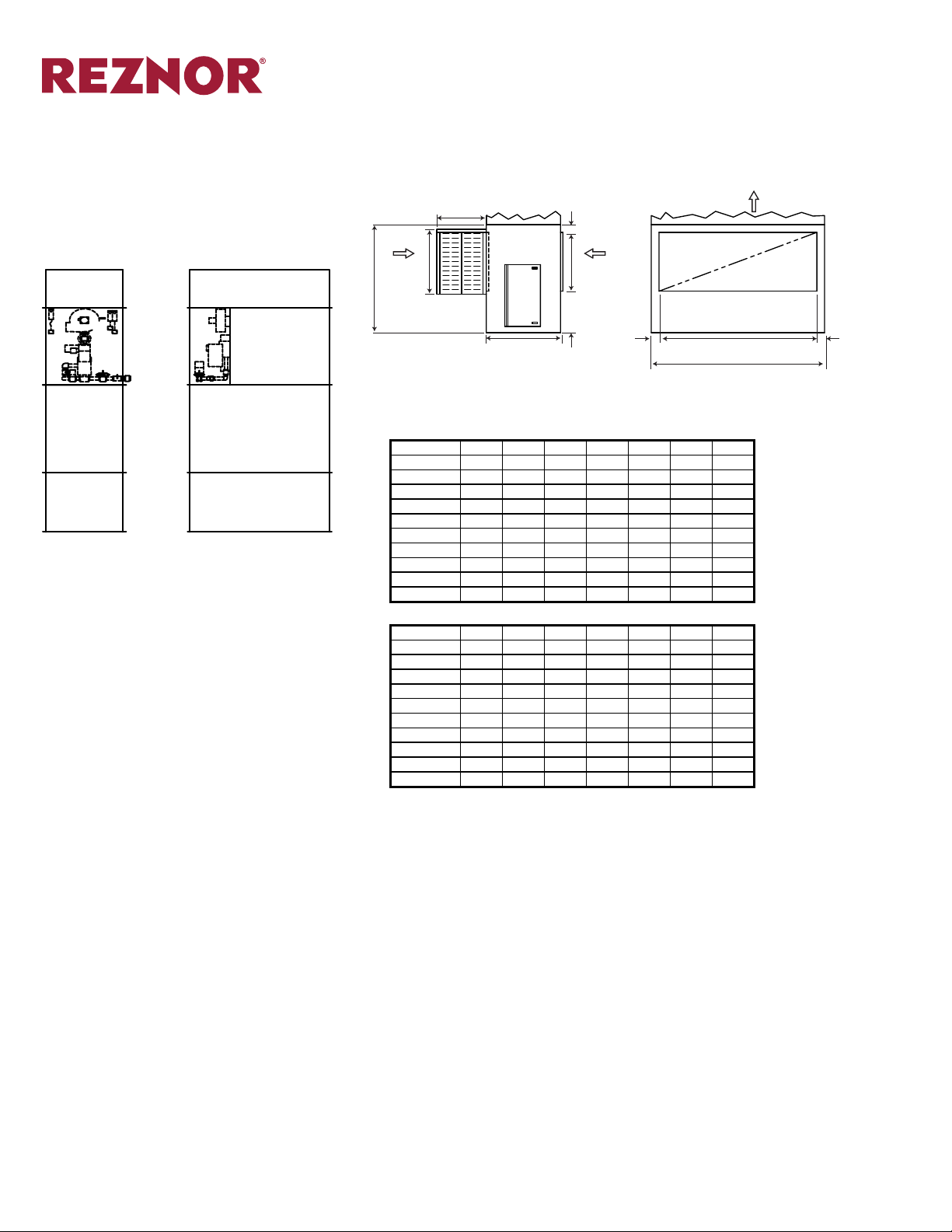
(127mm)
DIMENSIONS (cont’d)
HPCDV Accessories (“I” Conguration) (cont’d)
Tall Insulated Enclosed Mounting Base with Louvered Outdoor Air
Intake Hood (Outdoor)
±1/8” (3mm)
Page Number _______ of ______
G
5”
(127mm)
AIR
FLOW
DISCHARGE AIR
SECTION
BURNER
SECTION
BLOWER/FILTER
SECTION
INLET AIR
MOUNTING BASE
A
F D
OUTDOOR
AIR FLOW
B
Dimensions ±1/8”
Sizes A B C D E F G
20/25 55 38 62 20 52 30 18
35/40 55 38 78 20 68 30 32
45/55 61 42 90 26 80 36 32
65/75 61 42 110 26 100 36 46
85/100 67 54 110 32 100 36 46
125/150/175 73 60 132 38 122 48 60
200/250 95 66 156 60 146 75 75
275/300/325 95 71 176 60 166 75 75
350/400 105 86 196 70 186 82 75
500/600 115 86 216 80 206 92 75
Dimensions (±3mm)
Sizes A B C D E F G
20/25 (1,397) (965) (1,575) (508) (1,321) (762) (457)
35/40 (1,397) (965) (1,981) (508) (1,727) (762) (813)
45/55 (1,549) (1,067) (2,286) (660) (2,032) (914) (813)
65/75 (1,549) (1,067) (2,794) (660) (2,540) (914) (1,168)
85/100 (1,702) (1,372) (2,794) (813) (2,540) (914) (1,168)
125/150/175 (1,854) (1,524) (3,353) (965) (3,099) (1,219) (1,524)
200/250 (2,413) (1,676) (3,962) (1,524) (3,708) (1,905) (1,905)
275/300/325 (2,413) (1,803) (4,470) (1,524) (4,216) (1,905) (1,905)
350/400 (2,667) (2,184) (4,978) (1,778) (4,724) (2,083) (1,905)
500/600 (2,921) (2,184) (5,486) (2,032) (5,232) (2,337) (1,905)
RETURN
AIR FLOW
30”
(762mm)
5”
(127mm)
E
C
5”
END VIEWSIDE VIEW
Form S-PCD Page 26
Page 27

PIPING DIAGRAMS
5
4
BURNER
4
11
4
11
4
Page Number _______ of ______
9
8
11
10
CGA APPROVED GAS MANIFOLD
NOTES:
1. ON MANIFOLD SIZES 1-1/4” ON UP, ITEM 6 MUST
BE VENTED TO THE ATMOSPHERE
9
BURNER
7
5
8
11
15
10
ETL APPROVED GAS MANIFOLD
NOTES:
1. ON MANIFOLD SIZES 1-1/4” ON UP, ITEM 6 MUST
BE VENTED TO THE ATMOSPHERE
2. ITEM 7 IS PROVIDED WITH A PROOF OF CLOSURE
SWITCH
9
BURNER
7
5
8
13
15
10
7
14
17
17
17
3
2
6
3
6
3
6
1
LEGEND
1. Union Connection
2. Pilot Manual Shut-off Valve
3. Pilot Pressure Regulator
2
12
1
2
12
1
4. Pilot Automatic Safety Shut-off Valve
5. Pilot Manual Firing Valve
6. Main Burner Gas Pressure Regulator
7. Main Burner Auto Safety Shu-off Valve
8. Main Burner Test Firing Valve
9. Main Burner Orice
10. Modulating Gas Valve
11. 1/8” Test Port
12. Main Manual Valve
13. High Gas Pressure Switch
14. Low Gas Pressure Switch
15. Auxiliary Safety Shut-off Valve
16. Normally Open Vent Valve
17. Vent Limiter
F.M. APPROVED GAS MANIFOLD
NOTES:
1. ITEM 13 AND 14 ON UNITS OVER 2,475,000 BTUH
ONLY.
2. ITEM 15 ON UNITS ABOVE 400,000 BTUH ONLY
(MOTORIZED).
3. ON MANIFOLD SIZES 1-1/4” ON UP, ITEM MUST 6
MUST BE VENTED TO THE ATMOSPHERE.
4. ITEM 15 MAY BE REPLACED WITH A PROOF OF
CLOSURE SWITCH IN ITEM 7.
9
BURNER
8
13
10
I.R.I. APPROVED GAS MANIFOLD
NOTES:
1. ON MANIFOLD SIZES 1-1/4” ON UP, ITEM MUST 6
MUST BE VENTED TO THE ATMOSPHERE.
2. ITEMS 13 AND 14 ABOVE 400,000 BTUH ONLY.
3. ITEM 16 ABOVE 1,000,000 BTUH ONLY.
7
16
5
3
17
14
15
6
2
12
1
Form S-PCD Page 27
Page 28

AMPERAGE SPECIFICATIONS
Page Number _______ of ______
MOTOR
VOLTAGE/PHASE/CYCLES
HP 115/1/60 230/1/60 208/3/60 230/3/60 416/3/60 460/3/60 575/3/60
1/4 5.6 2.8 N/A N/A N/A N/A N/A
1/3 5.8 2.9 N/A N/A N/A N/A N/A
1/2 8.4 4.2 2.2 2 1.1 1 0.8
3/4 12 6 3 2.5 1.5 1.38 1.1
1 16 8 3.1 3.25 1.8 1.63 1.3
1 1/2 20 10 5.25 4.75 2.6 2.38 1.9
2 24 12 6.6 6 3.3 3 2.4
3 34 17 9.6 8.75 4.8 4.38 3.5
5 56 28 15.1 13.75 7.6 6.88 5.5
7 1/2 80 40 24 21.75 12 10.88 8.7
10 100 50 28.9 26.25 14.5 13.13 10.5
15 N/A N/A 44.2 40 22.1 20 16
20 N/A N/A 58 52.5 29 26.25 21
25 N/A N/A 74.5 67.5 37.3 33.75 27
30 N/A N/A 85.6 77.5 42.8 38.75 31
40 N/A N/A 115.9 105 58 52.5 42
50 N/A N/A 146.3 132.5 73 66.25 53
60 N/A N/A 165.6 150 82.8 75 60
75 N/A N/A 204.4 185 102.1 92.5 74
100 N/A N/A 270.5 245 135.2 122.5 98
125 N/A N/A 339.5 307 169.7 153.75 123
RUNNING MOTOR AMPERAGE
NOTES:
• To Calculate the Full Load Amps (FLA) = 1.25 x Largest Motor Draw + Additional Motor Draw at Face Value
+ Control Amperage (1.00 Amps Generally Cover 90% of MUA Applications).
• If You Require Specic Control Amperages Please Contact the Factory Representative.
Form S-PCD Page 28
Page 29

Type and Description
Casing
Blower/Motor Section
Heat Exchanger
Burner
Electrical Control Equipment
Page Number _______ of ______
SAMPLE SPECIFICATION
Model PCD
Furnish a Reznor Model (H)PCD(H)(V) indirect red self-contained make-up air unit in accordance with the following specications. The unit shall be ETL certied. Unit shall be designed for (indoor/outdoor) use.
The heater shall be designed to ensure a minimum efciency of 80% at full ring rate. The heat exchanger and
blower sections shall be constructed so they can easily be separated and reattached in the eld if necessary.
The unit shall be equipped to operate from a single point power connection. The heater shall be ame tested
before shipment and a detailed ame test report shall be kept on le by the manufacturer. Factory testing shall
be conrmed with a combustion analyzer and ow meter. The heater shall be shipped completely factory assembled and wired including all pre-piped manifold components and fuses, ready for immediate power and
fuel connections.
The unit exterior casing shall be heavy gauge galvaneal. (Unit roofs shall be sloped for water drain off and feature standing seam construction.) The entire unit casing shall be insulated with (1” thick 1.5 lb./1” thick 2 lb./2”
thick 3 lb.) berglass insulation with hard neoprene backing in a sandwich wall fashion. The unit exterior shall
be nished with (gray enamel/industrial catalyzed epoxy) nish. An integral welded iron channel frame shall
support the unit casing. Formed sheet metal bases are unacceptable. The structural iron frame shall be primed
and nished with industrial catalyzed epoxy paint. A 22 gauge (solid/perforated) liner shall be included.
The fan section and motor assembly shall be constructed in accordance with the requirements of the Air Moving and Conditioning Association (AMCA). The assembly shall be designed to house the fan(s), bearings, motor, and v-belts which shall be selected for at least 50% above the rated motor capacity. The fan(s) and motor
shall be mounted on a welded unitary base made of angle iron frame. The frame shall be primed and nished
with industrial catalyzed epoxy paint. The unitary base shall be provided with (1” deection spring/2” deection spring/1” external spring/2” external spring/rubber-in-shear/1” external spring hanger/2” external spring
hanger/pad-type seismic/hanger type seismic) vibration isolation. The blower section shall have a hinged access door to allow easy maintenance of lters and belts. The NEMA T-Frame (EPACT ODP/premium efciency
ODP/TEFC) motor shall be mounted on an adjustable base located within the fan section. The blower wheel
shall be statically and dynamically balanced, and mounted on a turned, ground and polished shaft with rigid
bearing supports. The shaft shall be designed with a maximum operating speed not exceeding 75% of the rst
critical speed. The bearings shall be ball bearing type L20 minimum life of 100,000 hours.
The heat exchanger shall be of four pass design with a primary combustion chamber and multi-tube secondary.
Internal turbulators or other ue restrictor to boost efciency are unacceptable. The entire primary heat transfer
surface shall be constructed of Type (409/304) Series stainless steel, and shall be cooled in its entirety by the
air to be heated. The Secondary heat transfer surface shall also be constructed from Type (409/304) Series
stainless steel. The stainless steel tubes shall be continuously welded into the secondary front and rear header
tube sheets to ensure an airtight seal. Mechanically swedging the tubes are unacceptable. All heat transfer
surfaces, including headers and the front collector box, shall be inside the casing and in the airstream. The
construction of the heat exchanger shall permit free, unrestricted lateral, vertical, and peripheral expansion during the heating and cooling cycle without damage or strain to any part. The heat exchanger shall be designed
to prevent contamination of heated air with the products of combustion. A spring loaded pressure relief door
with glass view port shall be provided. The entire heater casing shall be lined with a 22 gauge (solid/perforated)
liner.
The heater shall have of a power type 409 stainless steel burner, with integral combustion air blower and
motor; combustion air proving switch, removable pilot assembly and positive pilot combustion air supply. The
combustion air damper shall be interlocked with the main gas valve to insure a proper air/gas mixture. (A solid
state programmable safeguard relay with UV scanner and purge card shall continuously monitor main and pilot
ame.) The main and pilot valve train to the burner shall be completely factory pre-piped. This assembly shall
be wired and include the following minimum components; main and automatic shut off valves and adequate
unions and test ports for service. A 6,000 volt transformer shall accomplish ignition of pilot ame. The unit shall
be suitable for (natural gas and designed and certied by ETL to provide full gas modulation/propane/fuel oil).
(Depending on the burner selection, turndown from 100% to 7% of output are achievable.) Products of combus-
tion shall be vented through a (gravity/power) vent exhaust system.
Electrical assembly and components shall be in strict accordance with the latest provisions and requirements
of the Nation Electric Code. Unit shall be congured for (208/230/460/575) Volt, (1/3) Phase, 60 Hz supply voltage. Control cabinet shall be designed and constructed to ETL specications. A dead front safety disconnect
switch shall be mounted on the control enclosure door. Electrical cabinets shall be NEMA 12. (The cabinets
shall be located in a weather proof cabinet. Provisions for service padlocking shall be provided.) The following
items shall be located within the electrical enclosure: (fuses, starters, control relays, timing and holding relays,
resistors and numbered terminal strips). All components shall be labeled and cross referenced to control and
eld wiring diagrams. The control circuit shall be 110V, single phase. Wiring shall be neatly run in wiring duct.
Low and/or line voltage thermostats shall be furnished shipped loose for installation by others. (Unit shall be
equipped with automatic low limit freeze protection with bypass timer.) (Unit will feature a convenience outlet with separate disconnect, circuit breaker protection and supply transformer.) (Temperature control shall
consist of a solid state PID loop with adjustable setpoints.) (A discharge temperature sensor shall be wired in
series-parallel to room sensor.) (The temperature control system may be controlled by DDC at any time during
operation. DDC system may take control of blower/burner/dampers and modulating gas valve.) Unit shall be
congured for (left/right) side controls.
Form S-PCD Page 29
Page 30

SAMPLE SPECIFICATION (cont’d)
Model PCD
Page Number _______ of ______
Remote Control Panels
Mix Box and Filter Section
Additional Modules
(Remote NEMA 12 locking control panels shall be equipped with summer or winter switch and blower on,
burner on, ame failure and loaded lter lights. A remote adjustment potentiometer shall control damper posi-
tioning. A LCD display shall provide system temperature and setpoints.)
(A mix box with fresh air and return air dampers [and relief dampers] shall be provided. [The dampers are to be
aluminum airfoil low leak type with seals.] The dampers are to be inset into 22 gauge steel mix box liners. [The
dampers shall be equipped with modulation actuators.])
The blower section shall include a motor operated outside air intake sized for 100% outside air. The lters shall
be 2” pleated throwaway type with minimum of 85% arrestance and 30% dust. Filter access shall be through a
latched and gasketed access doors located on both sides of the unit.
Other eld installed modules/sections to include: (service platform/[3’/5’]mounting stand/louvered inlet plenum/
cooling coil/evaporative cooling/steam or hot water coil/return air blower).
(Screened plenum/4-sided louvered plenum/trapezoidal 3 facet cowl/[45°/90° louvered nozzles) shall be
shipped separately for eld attachment for discharge air distribution.
Form S-PCD Page 30
Page 31

Page Number _______ of ______
REZNOR® PRODUCT LIMITED WARRANTY
Reznor, LLC warrants to the original owner-user that this Reznor product will be free from defects
in material or workmanship. This warranty is limited to twelve (12) months from the date of original
installation, whether or not actual use begins on that date, or eighteen (18) months from date of
shipment by Reznor, LLC, whichever occurs rst.
LIMITATIONS AND EXCLUSIONS
Reznor, LLC obligations under this warranty and the sole remedy for its breach are limited to repair, at its manufacturing facility, of any
part or parts of its Reznor products which prove to be defective; or, in its sole discretion, replacement of such products. All returns of
defective parts or products must include the product model number and serial number, and must be made through an authorized Reznor
distributor or arranged through Reznor Customer Service. Authorized returns must be shipped prepaid. Repaired or replacement parts
will be shipped by Reznor, LLC F.O.B. shipping point.
1. The warranty provided herein does not cover charges for labor or other costs incurred in the troubleshooting, repair, removal, installation, service or handling of parts or complete products.
2. All claims under the warranty provided herein must be made within ninety (90) days from the date of discovery of the defect. Failure
to notify Reznor, LLC of a warranted defect within ninety (90) days of its discovery voids Reznor, LLC obligations hereunder.
3. The warranty provided herein shall be void and of no effect in the event that (a) the product has been operated outside its designed
output capacity (heating, cooling, airow); (b) the product has been subjected to misuse, neglect, accident, improper or inadequate
maintenance, corrosive environments, environments containing airborne contaminants (silicone, aluminum oxide, etc.), or excessive
thermal shock; (c) unauthorized modications are made to the product; (d) the product is not installed or operated in compliance with
the manufacturer’s printed instructions; (e) the product is not installed and operated in compliance with applicable building, mechanical, plumbing and electrical codes; or (f) the serial number of the product has been altered, defaced or removed (g) installation and
start-up procedures are not documented on the manufacturer’s start-up form at the time of installation.
4. The warranty provided herein is for repair or replacement only. Reznor, LLC shall not be liable for any loss, cost, damage, or expense
of any kind arising out of a breach of the warranty. Further, Reznor, LLC shall not be liable for any incidental, consequential, exemplary, special, or punitive damages, nor for any loss of revenue, prot or use, arising out of a breach of this warranty or in connection
with the sale, maintenance, use, operation or repair of any Reznor product. In no event will Reznor, LLC be liable for any amount
greater than the purchase price of a defective product. The disclaimers of liability included in this paragraph 4 shall remain in effect
and shall continue to be enforceable in the event that any remedy herein shall fail of its essential purpose.
5. THIS WARRANTY IS THE SOLE AND EXCLUSIVE WARRANTY FOR REZNOR PRODUCTS, AND IS IN LIEU OF ALL OTHER
EXPRESS AND IMPLIED WARRANTIES. REZNOR, LLC SPECIFICALLY DISCLAIMS ALL OTHER EXPRESS AND IMPLIED WARRANTIES, INCLUDING, BUT NOT LIMITED TO, ALL IMPLIED WARRANTIES OF MERCHANTABILITY AND FITNESS FOR A
PARTICULAR PURPOSE. No person or entity is authorized to bind Reznor, LLC to any other warranty, obligation or liability for any
Reznor product. Installation, operation or use of the Reznor product for which this warranty is issued shall constitute acceptance of
the terms hereof.
Form S-PCD Page 31
Page 32

Reznor® is your global source for heating,
ventilating and air conditioning equipment.
For more information on Reznor HVAC Equipment,
contact your local Reznor Representative by calling 800-695-1901.
Or, nd us on the internet at www.RezSpec.com
Specications & illustrations subject to change without notice or incurring obligations.
O’ Fallon, MO (02/16) © Nortek Global HVAC, LLC 2015. All Rights Reserved.
POD OG Form S-PCD-0216 Printed in U.S.A.
 Loading...