

Reznor FSV, FSH, FSV Mk 2, FSH Mk 2 Installation Servicing & Operating Instructions

Floorstanding
Oil Fired Heaters
FSV - FSH
(Mk 2)
0210-FS0GBEN
Installation
Servicing
&
Operating Instructions
Please read this document carefully before commencing the installation & leave it
with the user or attached to the appliance after installation.
Reznor U.K. Limited – Park Farm Road – Folkestone – Kent CT19 5DT – Tel 01303-259141 – fax 01303-850002

INDEX
1.0 Introduction
1.1 General Information
1.2 Quality Products
1.3 CE Approved European Directives
1.4 Product Information
1.5 Warning
2.0 Technical Specifications
2.1 Data Sheets
2.2 Dimensions
3.0 Mechanical/Electrical Services
3.1 Oil supply
3.2 Oil pipework
3.3 Electrical Connection
3.4 Ventilation Requirement
3.5 Electrical timer
4.0 Installation
4.1 Location
4.2 Heater Clearances
4.3 Flue
4.4 Nozzled Heaters
4.5 Ducted Heaters
4.6 Filters
4.7 Controls
5.0 Commissioning
5.1 Pre-Commissioning Checks
5.2 Commissioning Procedure
5.3 Commissioning Outlets
5.4 User Instructions
6.0 Instructions for Servicing
6.1 Frequency
6.2 Procedures
6.3 Re-Commissioning
7.0 Fault Finding
8.0 Spare Parts
8.1 3D Drawing
8.2 Parts List
9.0 Reference Standards
2/31

1.0 Introduction
1.1 General
1.1.1 Before installation check that the appliance as
described on the packaging label is in
accordance with the correct type and model
specified on the data plate and complies with
your customer order.
1.1.2 The heater is delivered wrapped in heavy duty
polythene and should be checked to ensure
that it has been delivered undamaged.
1.1.3 Please read this document before commencing
installation. The onus rests with the installer to
ensure that all relevant manuals are read and
understood, especially with regard to any
safety instructions stipulated by the
manufacturer.
1.1.4 These instructions are only valid for the country
of use indicated on the appliance, i.e. GB - IE.
If these symbols are not shown it is necessary
to obtain appropriate technical instructions
which will provide information concerning the
necessary modification of the appliance for use
in the country concerned. Such instructions
may be obtained from your supplier upon
request.
1.1.5 Check that the local distribution conditions of
electricity supply, type of oil and pressure and
adjustment of the appliance are compatible.
1.1.6 When installed in Great Britain the total
installation must comply with the requirements
and recommendations of the relevant British
Standards & local laws. The installation must
also be in accordance with the relevant
electrical regulations and I.E.E. regulations.
1.1.7 Warning! Unauthorised modification of this
appliance or departure from use in the manner
for which it was intended by the manufacturer,
or installation in a manner contrary to these
instructions may constitute a hazard and
jeopardise all warranties. Deviations should
only be carried out after formal consent has
been obtained from the manufacturer.
1.1.8 Caution! Ensure that the environment in which
the air heater is to be installed will not create a
hazard, i.e. where excessive (volatile) dust,
flammable or corrosive substances and/or
vapours and combustible materials may be
present. Suitable protection should be given to
prevent damage to the appliance, for example
from fork lift trucks.
1.1.9 These appliances have been tested and set
according to the data plate before leaving the
factory.
1.2 Quality Products
1.2.1 The Reznor range of oil fired floorstanding
heaters is manufactured in the EC and
supplied in accordance with BS EN 9002: 1994
Quality Assurance System.
1.2.2 Certificates of conformity are available from the
Quality Control department at Reznor Limited.
1.3 CE-Approval-European
Directives
1.3.1 Reznor floorstanding heaters have been fully
assessed and tested and meet the following
EC Directives:
- Machinery Directive (89/392/EEC)
- Low Voltage Directive (73/23/EEC &
93/68/EEC)
- Electromagnetic Compatibility Directive
(89/336/EEC & 91/36 EEC)
- Product Liability Directive (65/379/EEC)
1.3.2 In addition Reznor oil fired floorstanding
heaters are conform to the following
harmonised standards:
BS EN 292 - Part 1 :Safety of Machinery Basic Concepts, General Principles for
terminology, methodology
BS EN 292 - Part 2 :Safety of Machinery Basic Concepts, General Principles for Design
Technical Principles and Specifications.
BS EN 60204 - Part 1 :Safety of Machinery Electrical Equipment for Machine Specification
for General Requirements.
BS EN 60335 - Part 1 :Safety of Household
and Similar Electrical Appliances General
Requirements.
BS EN 55014 :Limits and methods of
measurement of radio disturbance
characteristics of electrical motor-operated and
thermal appliances for household and similar
purposes, electric tools and similar electric
apparatus.
prEN 50165 :Electrical equipment of nonelectric heating appliances for household and
similar purposes, safety requirements.
1.4. Product Information
1.4.1 Reznor floorstanding heaters are available with
burner outputs from 30kW to 293kW and can
be floor mounted (FSV units) or suspended
(FSH units).
Floorstanding heaters can be used in free
blowing or ducted applications. Each heater
must have its own individual open flue.
1.4.2 All floorstanding heaters are fitted with a pretested and set forced draught burner. A
sequential control box is fitted to each burner
to provide safety. Note: No asbestos or
soldered joints are present in the construction
of the heater.
1.4.3 All the materials selected can withstand the
range of chemical, mechanical and thermal
demands expected during the foreseen and
normal use of the product, as stipulated by
manufacturers' instructions and
recommendations.
1.4.4 Before final location of the product the following
criteria should always be considered in placing
the heater:-
• Flue outlet access
• Placing for efficient distribution of warm air
• Oil supply
• Electrical services
• Fresh air supply (when applicable)
• Service access and maintenance
requirements
1.5 Warning
Heaters should not be installed in a corrosive
or solvent atmosphere
(i.e. near plating or degreasing plants), in areas
where there is a fire risk, or any other
environment which is detrimental to the heater
or its operation. Consult BS 6230 for further
information on hazardous areas.
3/31

4/31
2.00
4.50 AND
2.00
3.50 AND
RL28.1 RL28.1 RL28.1
head ref
3000771
40 G20S ext.
1.50
3.00 AND
S+S
S+SS+S
29 44 60 88 117 150 175 205 235 293
psi 174 174 189 174 160 203 174 181 174 145
kW 38.0 57.1 76.1 114.2 152.2 190.2 228.3 257.5 304.4 336.5
Frame Size 1 2 3 4 5
2.0 Technical Specifications
FSV/FSH Model
2.1 Class D Oil (table 1a)
kW 35.5 53.4 71.1 106.7 142.2 177.8 213.4 241.6 284.5 315.6
Btu/h 129777 195007 259895 390013 519790 649567 779685 879409 1039580 1149208
Heat Input Gross
kW 31.0 44.1 60.5 87.9 119.3 148.0 178.0 202.9 234.4 268.9
Btu/h 121239 182371 242819 364400 485638 607219 728799 825107 971618 1077830
Heat Input Net
Btu/h 105871 150609 206618 300194 407431 505446 607902 692940 800518 918342
Heat Output
Burner Type Riello 40 G5 40 G5 40 G10 40 G10 40 G20 40 G20S
bar 12.0 12.0 13.0 12.0 11.0 14.0 12.0 12.5 12.0 10.0
Pump Pressure
Oil Consumption kg/hr 2.89 4.34 5.78 8.67 11.56 14.45 17.34 20.36 23.12 26.60
Size 0.65 1.00 1.35 2.00 2.75 2.75 4.00
Angle 60° 60° 60° 60° 45° 45° 60° 45° x 2 45° x 2 45° x 2
Shape SSSSSS S
Number FIXED FIXED 2.0 4.8 2.0 4.0 6.0 6.0 6.0 6.0
Number 2.25 3.75 3.4 5.0 5.5 4.5 5.5 2.1 2.8 3.0
Smoke No. 0-1 0-1 0-1 0-1 0-1 0-1 0-1 0-1 0-1 0-1
Nozzle
Head Setting (at 0 flue
resistance)
Air Setting (at 0 flue
resistance)
Air Setting Start Number n/a n/a n/a n/a n/a 3.5 4.0 n/a n/a n/a
°C 230 310 330 375 325 355 325 345 380 335
CO2 (1) % 11.1 11.5 11.7 11.5 12.0 11.9 12.6 12.0 11.7 12.8
Gross Flue Temperature
(20∞C ambient)
(1): CO2 figure can be subject to fluctuations in different installations on site (see § 5.2.1 /g)

17330
10315
8393
14100
7619
12800
6250
10500
8750
5208
7140
4250
30
25
30
25
25
20
98
82
98
82
82
66
49
49
47
50
50
49
5/31
88
87
84
89
90
88
21
69
50
69
59
59
ft
34
52
36
°K
89
61
93
65
°F
dB(A) 52 52 53 53 59 61 61 65 63 67
5180
3083
5180
3083
2500
1488
2500
1488
m³/h
ft³/min
Pa 95 95 130 130 125 150 200 250 160 250
21
18
18
m
FRAME size I II III IV V
table 1b
FSV/FSH model 29 44 60 88 117 150 175 205 235 293
Nominal air flow
Available outlet pressure
(ducted outlet)
Air throw (approx) (1)
Temperature rise through heater
(nominal)
Sound level (2) (for guidance
only)
Flue spigot outside diameter mm 125 125 150 178 178 178 178 223 223 223
Minimum flue height m 2 22222222 2
Main fan motor size kW 0.55 0.55 0.736 0.736 1.5 2.2 3 4 4 5.5
Total absorbed electric power kW 0.91 0.91 1.60 1.60 2.41 2.76 4.60 5.80 5.47 8.39
Electrical supply 230/240V – 1N E 50Hz 400/415V – 3N E 50Hz
Inlet oil connection ins BSP 3/8 3/8 3/8 3/8 3/8 3/8 3/8 3/8 3/8 3/8
Weight (without burner) kg 190 190 225 225 280 292 300 320 360 380
(1) : unobstructed in still air with a terminal velocity of 50ft/min.
(2) : Condition R=5m; Q=2; A=160; louvres in neutral position

2.2 Dimensions
Figure 1a : unit with discharge nozzle
Vertical heater range
Front view
Figure 1b : unit with discharge plenum
Front view
6/31
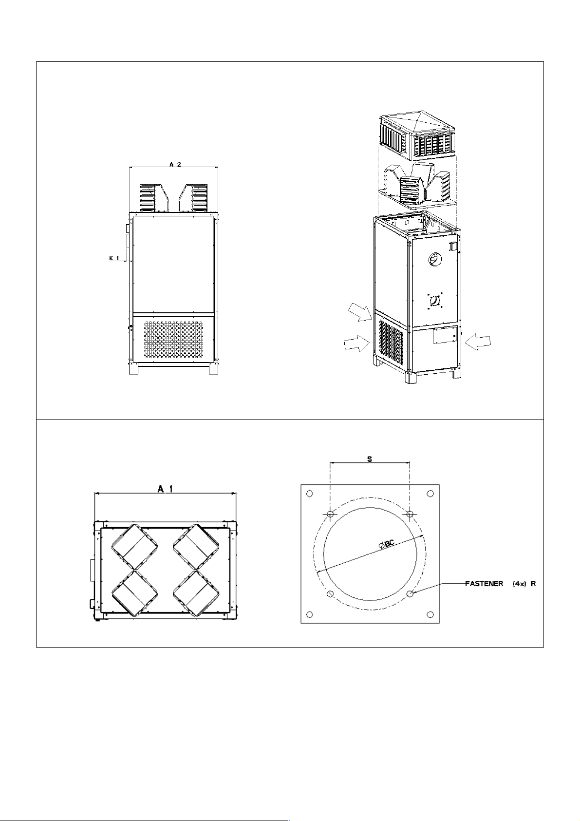
Figure 1c – Side view
Figure 1d
Figure 1e
air inlet
Figure 1f : burner mounting flange
air inlet
7/31

Figure 2a – Side view
Horizontal heater range
Figure 2b – Front view
Remark :
The fixation eyes (4x dia 22.5) may only be used to put the unit into horizontal position after delivery. It is strictly forbidden
to use the fixation eyes for suspending the unit.
8/31

Dimensions (mm) (table 2)
FSV/FSH 29 44 60 88 117 150 175 205 235 293
Frame size I II III IV V
A1/A2 613 613 859 859 1158 1158 1305 1305 1504 1504
C1/C2/C3 865 865 865 865 795 795 1186 1186 1186 1186
D1/D2/D3 1007 1007 1019 1019 1041 1041 1184 1184 1111.5 1111.5
E1/E2/E3 1441 1441 1465 1465 1637 1637 1750 1750 1677.5 1677.5
outside dia 2
(flue outlet)
125 125 150 150 178 178 178 223 223 223
F1/F2/F3 1804 1804 1804 1804 2012 2012 2073 2073 2012 2012
inside dia 1
(burner inlet)
110 110 120 120 140 140 155 155 155 155
H1 2088 2088 2168 2168 2376 2378 2477 2477 2466 2466
H2 2164 2164 2114 2114 2400 2400 2395 2395 2334 2334
K1/K2 35.5 35.5 107.5 35.5 32 32 105.5 33.5 32.7 32.7
L 520 520 591 591 675 675 786 786 675 675
M 1284 1284 1213 1213 1337 1337 1287 1287 1337 1337
P1 284 284 364 364 364 366 404 404 454 454
P2 360 360 310 310 388 388 322 322 322 322
dia BC 142 142 145 145 162 162 180 224 180 224
R M8M8M8M8M8M8M8M8M8M8
S 100.4 100.4 102.5 102.5 114.5 114.5 127.3 158.4 127.3 158.4
2.3 Number of nozzles on heaters (figure 3)
29 - 44 60 - 88 117 - 293
9/31

3.0 Mechanical/Electrical Services
3.1 Oil supply
3.1.1 Connection to an oil supply may only be
carried out by suitably qualified persons.
The oil installation must comply with the
rules in force using materials appropriate for
oil installations.
3.2.7 All pipework must be adequately sealed
using approved sealing compounds suitable
for oil.
GALVANISED PIPEWORK AND FITTINGS
MUST NOT BE USED.
The pipework must be effectively sealed so
as to eliminate the ingress of air which will
ultimately stop the flow of oil.
3.1.2 Check that the oil grade is in accordance
with the data described on the air heater.
3.1.3 An adequate oil line sized to provide the
dynamic pressure for the volume required
by the air heater(s) is essential to maintain
the nominal heat input.
3.1.4 A shut off tap and, to facilitate servicing, a
disconnect union fitting must be provided
adjacent to the appliance.
3.1.5 Ensure that the installations a filter and has
been tested and purged in accordance with
prescribed practice prior to commissioning
and taking the air heater into service.
3.2 Oil Pipework
3.2.1 The burners fitted to the Reznor air heaters
are suitable for Class D (35 sec) oil via a
suitable oil pipeline and filter to a storage
tank installed externally to the building.
3.2.2 The pipework can be constructed for use on
either a single pipe, or two-pipe system.
Whether a gravity feed or pumped system is
required is determined by the parameters of
the installation i.e. number of heaters and
length of pipeline.
3.2.3 Please refer to the burner manual as to the
limitations of the oil line and most suitable
pipe diameters after deciding on which
pipework system to adopt.
3.2.4 The storage tank and heater are to be
installed with the appropriate safety/service
components as shown by the following
figures.
Tank and single pipe system
Pressure ring main.
3.3 Electrical connection
3.3.1 The electrical installation may only be
carried out by suitably qualified persons
observing the rules in force.
3.3.2 Check that the electrical specification is in
accordance with the specified data on the
air heater. A unique appliance wiring
diagram is supplied as a separate document
attached to this one, plus an additional copy
attached to the air heater.
3.3.3 These appliances must be earthen.
3.3.4 A lockable main switch must be installed
adjacent to each appliance and in view
when facing the service compartment. The
isolator must have a contact separation of at
least 3.0mm on all poles.
3.3.5 Ancillary controls (option 910.2) may be
included with the heater to provide timed
heat cycles, room comfort temperature
level, frost protection, override air
circulation, etc.
3.3.6 Ensure when planning the external
appliance control circuitry that power will be
supplied at all times to the air heater, even
when it is control switched in the ‘heat-off’
mode. This is necessary to ensure that the
fan can operate independently of the
heating control. Therefore never incorporate
automatic controls that electrically isolate
the appliance.
Figure 4 : Option 910.2
3.2.5 Any external piping from the tank or filter
should be adequately lagged to avoid
waxing during the winter.
Always ensure the correct grade of fuel is
used and especially ensure winter grade is
used for the winter period, as this will be
suitable down to –12°C whereas summer
grade will wax and plug the filter at –4°C.
3.2.6 When using a pumped ring main ensure that
correct pressure regulating valves are used
prior to each heater and a ring main
pressure below 0.4bar is used to avoid
aeration and consequential ‘air locks’.
Legend
1 frost stat 4 fan control
2 room stat 5 burner control
3 programmable clock 6 fuse
10/31
 Loading...