

Page 1
EXUBEXUBEXUB
Explosion Resistant Unit Heater
Owner’s Manual
This manual covers installation, maintenance,
repair, and replacement parts.
Forced-Air Heater for Hazardous Locations
Class I, Divisions 1 & 2, Groups C & D
Class II, Divisions 1 & 2, Groups F & G
Temperature Code T3B
————————————————————————————————————-
Class I, Zones 1 & 2 , Groups IIA & IIB, T3
WARNING!
Please adhere to all instructions published in this manual.
Failure to do so may be dangerous and may void your warranty.
Note: EXUB heaters should not be exposed to rain or snow. This applies to installed & stored heaters.
The EXUB heater should not be modified in any way.
(35 kW = T3A)
235730
www.RezSpec.com
Printed in Canada
Part No. RZ-I-EXUB (B)
Page 2
EXUB Model Coding
EXUB 10 AK7E Options - A
Model Code Sequence
Factory
Assigned
Model Series
Power Output
5 kW 5
7.5 kW
10 kW
15 kW
20 kW
25 kW
30 kW
35 kW 35
7
10
15
20
25
30
12 inch fan size
12 inch fan size
12 inch fan size
16 inch fan size
16 inch fan size
20 inch fan size
20 inch fan size
20 inch fan size
* 120 Volt Control Circuit is standard
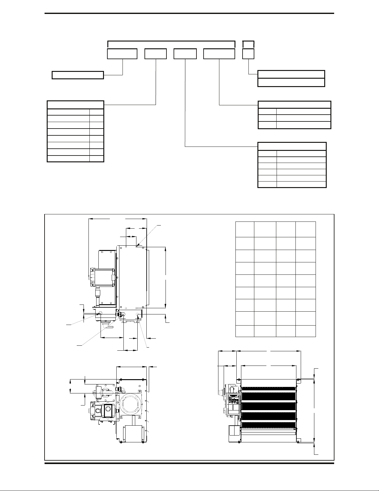
EXUB Physical Dimensions
G max
11"
[279]
A
3/4" NPT,
External thermostat
entry
0.375"
[10]
1" NPT,
Main electrical entry
for disconnect option
1" NPT,
Main electrical entry
no disconnect fitted
3.75"
8.4"
[214]
5.0"
[127]
[95]
4 x Ø 9/16" [14]
mounting holes
B
2.25"
[57]
3.375"
[86]
Louvres
1.4" [36] max
4.7"
[118]
6.6"
[168]
Heater
Size
Dim.
A
B
C
D
E
F
G
Product Revision No.
For minor revisions
Factory Built-in Options
BT1* 24 Volt Control Circuit
Integral thermostat
IX34
Disconnect switch
BAX1
Heater Line Voltage/Phase
AK2 208 Volt/ 1 Phase
AK5 208 Volt/ 3 Phase
AK3E 240 Volt/ 1 Phase
AK6E 240 Volt/ 3 Phase
AK7E 480 Volt/ 3 Phase
AK8E 600 Volt/ 3 Phase
12
(5-10kW)
Inches
(mm)
7.5
(190.5)
18.19
(462)
16.3
(414)
19
(483)
19.45
(494)
3.1
(79)
22.25
(565)
16
(15-20kW)
Inches
(mm)
7.5
(190.5)
22.28
(566)
20.28
(515)
23
(584)
23.46
(596)
5.1
(130)
22.25
(565)
20
(25-35kW)
Inches
(mm)
7.5
(190.5)
26.26
(667)
24.29
(617)
27
(686)
27.44
(697)
7.1
(180)
23.25
(591)
E
C
0.25"
[6]
F
F
3.375"
[86]
2
D
0.25"
[6]
Page 3
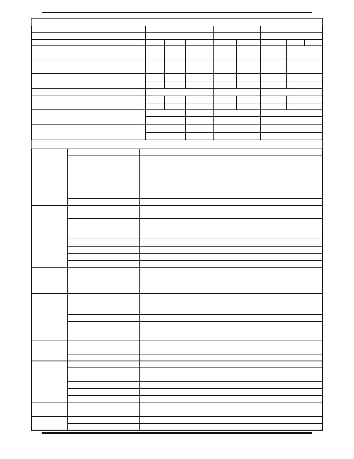
EXUB Specifications By Model Size
Model 5 to 10 kW 15 to 20 kW 25 to 35 kW
Fan Diameter in. (mm) 12 (304.8) 16 (406.4) 20 (508.0)
Nominal kW 5 7.5 10 15 20 25 30
Air Delivery CFM 400 600 800 1200 1700 2100 3000
m3/hr 680 1019 1359 2039 2888 3568 5097
Approx. Air Velocity FPM 479 718 958 808 1145 916 1309
m/s 2.4 3.6 4.9 4.1 5.8 4.6 6.6
Approx. Horizontal Air Throw ft 15 22 30 33 46 41 61
m 4.6 6.7 9.1 10.1 14.0 12.5 18.6
Motor Power HP (Watts) ¼ (186) ¼ (186) ½ (373)
Maximum Mounting Height ft 7 7.5 9.5 10 11 12 15
(to underside of heater) m
Approx. Net Weight (without disconnect)
Lbs (kg) (with disconnect)
Approx. Shipping Weight (without disconnect)
Lbs (kg) (with disconnect)
EXUB General Specifications
Certification
2.1 2.3 2.9 3.0 3.4 3.6
129 (58.5) 133 (60.3) 161 (73.0) 192 (87.1)
142 (64.4) 146 (66.2) 174 (78.9) 205 (92.9)
188 (85.3) 192 (87.1) 224 (101.6) 261 (118.4)
201 (91.2) 205 (93.0) 237 (107.5) 274 (124.3)
CSA
235730 - Certified to Canadian and U.S. standards
C/US
Class I, Divisions 1 & 2, Groups C & D
Class II, Divisions 1 & 2, Groups F & G
Temperature Code T3B (35 kW =T3A)
Class I, Zones 1 & 2, Groups IIA & IIB, T3
Approvals
North American
Hazardous Location
Classifications
————————————————————————————————————————
Temperature Code Division System - T3B 165°C (329°F); Zone System - T3 200°C (392°F)
14-gauge (0.075 in.) (1.9 mm) steel. Red epoxy/polyester powder coated
with five-stage pretreatment, including iron phosphate.
Split design with close wire spacing. A 3/8 in. (9.5 mm)
diameter probe will not enter. Black polyester powder coated.
Cabinet
Cabinet Material
Fan Guard
Louver Blades Anodized extruded aluminum.
Conduit Materials & Fittings Plated steel and aluminum alloy for corrosion resistance.
Fasteners Zinc plated steel for corrosion resistance.
Enclosures Cast aluminum (non-copper alloy) NEMA Type 7 & 9 with O-ring.
Mounting Holes 9/16” diameter holes – Four located on the top face of heater.
35
4.6
Motor/Fan
Heat
Exchanger
Protection
Controls
Load
Isolation
Operating
Limits
Motor Type
Explosion-proof, thermally protected, 1725 RPM permanently lubricated
ball bearing type with 56 frame and “easy-off” fan blade replacement feature.
Fan Three-blade aluminum, steel spider and hub with 5/8 in. bore
Heating Elements
Long-life, low watt-density, high grade metal-sheathed
elements.
Heat Transfer Fluid Ethylene glycol and water including corrosion inhibitors.
Header Material Carbon steel.
Carbon steel shells and carbon steel tubes with copper-free,
roll-formed aluminum fins @ 10 fins per in. Evacuated and sealed. Sprayed
ExCaliber
TM
Core
with black, high heat enamel paint.
Temperature High Limits
One automatic reset rated for 100,000 cycles, and one manual reset. Both
are snap-action bimetal type, open on temperature rise.
Pressure Relief High-quality preset 100 psig (689 kPa) stainless steel pressure relief device.
Control Circuit Built in 120 V control. Optional 24V control (recommended) is available.
Control Contactor
40 FLA (50 A resistive per pole) Definite Purpose.
Rated for 500,000 mechanical operations.
Control Transformer Multitap primary, 120V or 24V secondary.
Fuse Protection Thermal delay fuse with spare, .25”
Room Thermostat (optional) Built in, explosion-proof thermostat, 40°F to 80°F (5°C to 27°C)
Disconnect Switch (optional)
Built-in, explosion-proof disconnect switch, 600V, 50A max with lock-out fea-
ture. Also available in a wall mount version.
x 1.25” , 120V = 1/4 A, 24V = 1 A.
Ambient Temperature -40°F to 104°F (-40°C to 40°C). Storage: -40°F to 140°F (-40°C to 60°C)
Maximum Altitude 10,000 ft (3048 m) above sea level.
3
Page 4

— WARNING! —
Read and follow the instructions in this manual. Failure to do so may result in severe or fatal injury.
IMPORTANT SAFETY INFORMATION
1. Heater is to be connected and serviced only by qualified electrician experienced with hazardous location
equipment. It is the responsibility of the installer to verify the safety and suitability of the installation.
2. Installation and wiring of the heater must adhere to all applicable codes. Heater must be effectively grounded to eliminate shock hazard.
3. Heater is to be used only in atmospheres having an ignition temperature higher than the heater’s maximum
rated operating temperature as shown on the heater data plate. For details of hazardous locations with
potential for explosion, refer to the Canadian Electrical Code, Part 1, Section 18 or Articles 500 through 516
of the National Electrical Code.
4. Do not operate heater in ambient temperatures above 40
5. Do not plug heater outlet with gloves, clothing, etc. or operate heater with louvers fully closed.
6. Explosion/Electric Shock Hazard. Disconnect heater from power supply or fuse box before opening enclosures or servicing heater. Lock the switch in the “OFF” (open) position and/or tag the switch to prevent
unexpected power application.
7. Operate the heater only while it is permanently mounted in an upright position. Failure to comply will cause
overheating of the heat exchanger and shutting down of the unit by tripping the high temperature cutout.
8. This heater is equipped with two bimetal thermal high-limit cutouts, one automatic reset type and one
manual reset type. The heater is not to be operated with the high-limit cutouts disabled or disconnected
from the control circuit.
9. Keep all electrical enclosure covers tightly closed and secured with all bolts and threads. Cover joints must
be clean before replacing covers. Keep away from rain or snow. Heater is for dry indoor use only.
10. All unused threaded openings not used for supply wiring or remote mount room thermostat must be fitted
with threaded plugs approved for use in hazardous locations.
11. The heat exchanger is a factory vacuum-sealed unit. Do not attempt to loosen or tighten the vacuum plug or
pressure relief device. A loss of vacuum could cause nuisance tripping of the thermal cutouts or high
pressures which will cause the relief device to actuate with an accompanying loss of fluid.
12. The heat exchanger is filled with a mixture of water and inhibited ethylene glycol which is poisonous.
Contact with the fluid at operating temperatures may produce a burn hazard. Suggested first aid consists of
flushing eyes with plenty of water and to wash off skin in flowing water or shower. If any fluid leakage occurs
from the heater, disconnect it from the power supply and have the heat exchanger replaced with a factory
supplied unit.
°C (104°F).
13. Heater must be kept clean. When operating in a dirty environment, regularly clean the fin tubes, fan, and fan
guard. Refer to recommended maintenance procedures.
14. Do not operate heater in atmospheres which are corrosive to aluminum or steel.
15. See applicable electrical codes for seal requirements in field installed conduits. Factory installed conduits
require no further sealing.
16. Crackling or pinging noises within the heat exchanger during start up may occur. This is normal.
17. Air discharge at the bottom of the heater may be warmer than at the top. This is normal.
18. Do not attempt to install a Remote Fan Only Switch. Do not modify the heater in any way.
19. Use factory approved replacement parts only.
20. Contact factory for any questions or concerns.
4
Page 5
— WARNING! —
Read and follow the instructions in this manual. Failure to do so may result in severe or fatal injury.
— INSTALLATION —
Mechanical
Location
Please follow guidelines below for optimum heating results:
1. Do not install heaters such that airflow is blocked or impeded by equipment or walls.
2. For occupant comfort, position heaters so that air discharge is directed across areas of highest heat loss,
such as doors, windows, and outside walls.
3. For large areas, arrange heaters such that the air discharge of one heater is directed towards the inlet of the
next heater. This sets up a rotational airflow with air circulation in the central area of the building.
4. For equipment freeze protection, direct air discharge at equipment.
5. For large workshops or warehouses it may be acceptable to use fewer, larger heaters.
6. Locate remote mount room thermostat on interior partition walls or posts away from cold drafts, internal heat
sources, and away from heater discharge air streams.
Mounting
1. A variety of mounting brackets are available from the factory to aid in installation.
2. The heater is designed to be installed in an upright and level position. All models should not be more than
±15 degrees or 2.5 in. (63.5 mm) from level when measured front-to-back, and ± 5 degrees 1.7 in. (43.2
mm) on 5 to 10 kW models, 2.0 in. (50.8 mm) on 15 to 20 kW models, and 2.4 in. (60.9 mm) on 25 to 35 kW
models from level when measured side-to-side. Failure to comply will cause high limit shut down. Refer to
heater data plate for tilt angles.
3. If using mounting hardware or a supporting structure not supplied by the factory, the unit should be
suspended through the four 9/16 in. (14 mm) mounting holes on top of the unit with 1/2 in. UNC bolts.
Lock washers should be used on all mounting nuts and bolts to ensure they don’t vibrate or work loose
due to fan vibration or other vibration transmitted to the heater. If in doubt consult factory.
4. It is essential that adequate structural support be provided for installation. The mounting structure must
be strong enough to support the heaters weight, provide sufficient stiffness to prevent excessive
vibration, and withstand all probable abusive situations such as transportable installations where truck offloading impacts, etc. may occur. Refer to table on Page 3, EXUB Specifications by Model Size, for heater
net weights.
Mounting Heights and Clearances
1. To ensure that warm air reaches the floor observe the recommended maximum mounting heights in table
on Page 3, EXUB Specifications by Model Size. Heaters may be mounted at higher elevations and still provide warm air at floor level however, the maximum mounting elevation at which this occurs depends on location and operational conditions.
2. Louvers may be adjusted to provide greater downward deflection of the discharge air. However, louvers
must not be set less than 30 degrees of the closed position.
3. Leave at least 10 in. (254 mm) clearance between the rear of the motor and the nearest obstruction.
4. For easy removal of the core, leave clearance beneath the heater equal to the height of the heater cabinet
plus 2 in. (51 mm).
5
Page 6

— WARNING! —
Read and follow the instructions in this manual. Failure to do so may result in severe or fatal injury.
— INSTALLATION —
Electrical
1. Heater is to be connected and serviced only by qualified electrician experienced with hazardous location equipment. It is the responsibility of the installer to verify the safety and suitability of the installation.
2. Explosion/Electric Shock Hazard. Disconnect heater from power supply or fuse box before opening enclosures or servicing heater.
Lock the switch in the “OFF” (open) position and/or tag the switch to prevent unexpected power application.
3. Use copper conductors only for supply wires and approved explosion-proof means of wiring during installation. Use minimum 90°C
rated wire. Refer to “Supply Wire Requirements” table and heater data plate for conductor wire rating.
4. Installation must include appropriate over-current protection devices (fusing or circuit breakers) as required by the CEC or NEC.
Refer to “Supply Wire Requirements” table and heater data plate
for current ratings. Supply voltage is to be within 10% of the data
plate voltage.
5. Confirm that the electrical power supply matches the nameplate
voltage, phase, amperage and frequency rating of the heater to be
connected.
6. Supply conductors and ground conductor pass through the 1 in.
NPT rigid conduit opening on the control enclosure.
7. Proper installation of the heater requires that an adequate grounding conductor be connected to the ground terminal. This terminal is
made of copper and is located on the top right-hand corner of the
printed circuit board within the control enclosure.
8. Heater may be supplied with a factory installed integral room thermostat (See Figure 1). On heaters not supplied with this option, it
is recommended that an external explosion-proof room thermo-
stat be used. The wiring to the external thermostat must be copper
wire, 16 gauge minimum (for Class II) or 14 gauge minimum (for
Class I). Thermostat conductors may also be passed through the 1
in. NPT conduit opening or through the convenient 3/4 in. NPT
dedicated external thermostat conduit opening in the enclosure.
Connect the external thermostat conductors to the printed circuit
board terminal block marked “T’STAT”. The built-in control transformer supplies the heater with either 120V or 24V for internal unit
operation. This voltage will appear across the thermostat contacts
when they are open. The minimum thermostat contact rating
should be 1 amp @ 120 VAC. Refer to nameplate for control voltage of unit.
9. Refer to wiring diagram on Page 9 to ensure that all connections
are as required and securely fastened.
10. For heaters supplied with a factory installed integral disconnect
switch (See Figure 1), field wiring is as follows:
a. Remove the Disconnect cover assembly from the base by removing the six (6) cover bolts. Set the cover
assembly aside. CAUTION: Damaging the mating surfaces of the enclosure could destroy the flame path
and jeopardize the integrity of the flame proof enclosure.
b. Supply conductors and ground conductor pass through the 1 in. NPT rigid conduit opening located on the
top or bottom of Disconnect Enclosure. Supply conductors to be wired to DIN rail mounted Disconnect
Switch inside. Ground conductor to be wired to Ground Lug fastened to inside of Disconnect Enclosure.
Refer to wiring diagram on Page 9.
c. Attach cover to the enclosure using the six (6) bolts. Tighten to 150 inch-pounds ± 5 in-lbs.
11. All unused threaded openings in enclosures, not used for supply wiring or external room thermostat, must be fitted with threaded plugs
approved for use in hazardous locations (included). Factory installed conduits require no additional sealing.
12. Installer must seal each conduit run within 18” (457 mm) of enclosure. This seal must be suitable and listed for hazardous locations.
13. Ensure that input conductors and conduit have adequate strain relief at installation.
14. Before application of electrical power, recheck all connections to ensure compliance with the wiring diagram and any code requirements. Remove any foreign objects from the control box and heater. Reinstall cover tightly.
15. On all three-phase heaters, it is necessary to verify that the fan rotation is correct (counter clockwise when facing the rear of the
heater). If air delivery is not from the front of the heater, reverse any two supply leads at the main power contactor located in the
control enclosure.
16. The explosion-proof control enclosure and element enclosures are designed with O-rings, threaded joints and metal-to-metal contact at
the lid or cover joint to prevent an explosion. Do not attempt to install gasket material of any type at these joints. A light coating of antiseize compound may be applied to the threads to prevent seizing.
EXUB Supply Wire Requirements
Model
EXUB5AK2
EXUB5AK3E
EXUB5AK5
EXUB5AK6E
EXUB5AK7E
EXUB5AK8E
EXUB7AK2
EXUB7AK3E
EXUB7AK5
EXUB7AK6E
EXUB7AK7E
EXUB7AK8E
EXUB10AK3E
EXUB10AK5
EXUB10AK6E
EXUB10AK7E
EXUB10AK8E
EXUB15AK5
EXUB15AK6E
EXUB15AK7E
EXUB15AK8E
EXUB20AK7E
EXUB20AK8E
EXUB25AK7E
EXUB25AK8E
EXUB30AK7E
EXUB30AK8E
EXUB35AK7E
EXUB35AK8E
kW Volts Ø
5 208 1 26.5 33.2 35 8
5 240 1 23.3 29.2 30 10
5 208 3 14.6 18.2 20 12
5 240 3 12.7 15.9 20 12
5 480 3 6.7 8.4 15 14
5 600 3 5.5 6.9 15 14
7.5 208 1 38.6 48.2 50 6
7.5 240 1 33.8 42.2 50 8
7.5 208 3 21.5 26.9 30 10
7.5 240 3 18.7 23.4 30 10
7.5 480 3 9.7 12.2 15 14
7.5 600 3 7.9 9.9 15 14
10 240 1 44.2 55.2 60 6
10 208 3 28.5 35.6 40 8
10 240 3 24.8 30.9 35 8
10 480 3 12.7 15.9 20 12
10 600 3 10.3 12.9 15 14
15 208 3 42.3 52.9 60 6
15 240 3 36.8 46.0 50 6
15 480 3 18.7 23.4 25 10
15 600 3 15.1 18.9 20 12
20 480 3 24.8 30.9 35 8
20 600 3 19.9 24.9 25 10
25 480 3 31.1 38.8 40 8
25 600 3 25.1 31.3 35 8
30 480 3 37.1 46.4 50 6
30 600 3 29.9 37.3 40 8
30 480 3 43.1 53.9 60 6
30 600 3 34.7 43.3 50 6
Current
Total
Amps
Minimum
Circuit
Ampaci ty
Max F
use
Amps
Figure 1
Supply
Wire
90°C (AWG)
6
Page 7

— WARNING! —
Heater is to be serviced only by qualified electrician experienced with hazardous location equipment.
Explosion/Electric Shock Hazard. Disconnect heater from power supply or fuse box before opening
enclosures or servicing heater. Lock the switch in the “OFF” (open) position and/or tag the switch to prevent
unexpected power application.
— Repair and Replacement —
Heat Exchanger Replacement
The heat exchanger has been air evacuated, fluid filled, and sealed at factory and is not field repairable. Replacement heat
exchangers are available from the factory and are inspected and electrically tested for correct heat output and proper
operation of the high-limits.
1. Explosion/Electric Shock Hazard. Disconnect heater from power supply or fuse box before opening enclosures or
servicing heater. Lock the switch in the “OFF” (open) position and/or tag the switch to prevent unexpected power application.
2. To prevent burn hazard, be sure heat exchanger and fluid has been allowed to cool before proceeding.
3. Remove cabinet bottom panel, element housing cover, element enclosure cover, & control enclosure cover.
4. From the control enclosure, disconnect two high-limit wires from printed circuit board terminal block marked 3 & 4 and
disconnect three output heating element wires from contactor terminals marked T1, T2, & T3.
5. Slightly loosen all cabinet bolts and louver screws to prevent heat exchanger from binding.
6. The heat exchanger is secured by three 1/4 in. bolts on the right-side cabinet panel (when facing front of heater) and
one 1/4 in. bolt located on the left side of heater. On 5 - 10kW models the left-side bolt is located at the top right-hand
foot of control enclosure. On 15 - 35kW models the left-side bolt is located above the control enclosure. With an assistant supporting the weight of the heat exchanger remove these 4 bolts. Carefully lower the heat exchanger from the
cabinet.
7. Reverse the above procedure when installing a new heat exchanger.
Temperature High-Limit Replacement
This heat-exchanger includes one automatic reset & one manual reset temperature high-limit that are wired in series. The
automatic reset high-limit is rated for 100,000 cycles and is for a temporary failure condition. Continuous nuisance tripping
of the automatic reset is generally not the fault of the high-limit but is usually caused by incorrect operating voltage, blocked
air inlet or outlet, fan/motor malfunction, high ambient temperatures, excessively dirty heat exchanger or leaking heat exchanger. Care should be taken to determine the exact reason that the automatic reset high-limit control tripped so
the problem can be resolved immediately. The automatic reset high-limit normally fails in the open position, however, it
can also fail closed.
If the automatic reset fails in the open position the heater will not function and the high-limit should be replaced. The
occurrence of the manual reset high-limit control to trip is an abnormal condition and indicates that the automatic
reset high-limit has failed in the closed position. If this occurs remove the heater from service immediately and
replace the automatic reset high-limit. Determine the exact reason that the automatic reset high-limit control
tripped so the problem can be resolved immediately. If the manual reset high-limit shuts down the heater it will have to
be reset by pressing on the small reset button protruding from the center of the high-limit device.
1. De-energize the heater electrical supply circuit.
2. Remove element housing cover, and element enclosure cover.
3. Remove spade connection from the automatic reset high limit lugs.
4. Remove automatic reset high-limit assembly by unscrewing, and clean the inside of the thermowell. A clean thermowell
ensures good thermal contact.
5. Replace high-limit with a factory supplied unit only. Apply a small drop of heat sink conductive cement around the base
of the high-limit, but not on the threads, and screw into thermowell. Attach spades to automatic reset high-limit .
6. Replace control enclosure cover, element housing cover, and element enclosure cover.
7. Energize the heater electrical supply circuit and let run for 15 minutes to reach a stable operating temperature.
8. If heater operation appears to be normal, place unit into service.
7
Page 8

— WARNING! —
Heater is to be serviced only by qualified electrician experienced with hazardous location equipment.
Explosion/Electric Shock Hazard. Disconnect heater from power supply or fuse box before opening
enclosures or servicing heater. Lock the switch in the “OFF” (open) position and/or tag the switch to prevent
unexpected power application.
— Repair and Replacement, Continued —
Fan, Fan Guard or Motor Replacement
The motor is a sealed unit that requires no lubrication. If the motor is defective, it must be replaced with
an original factory supplied motor.
1. Remove four bolts holding motor to the motor mount, and covers from junction box and control enclosure.
On units with an integral room thermostat, remove 4 bolts on front face of thermostat enclosure .
2. Detach and remove two-piece fan guard assembly by removing top and bottom screws that attach the fan
guard to the cabinet.
3. Loosen fan blade set screw and remove fan blade from end of motor shaft leaving it in fan panel opening.
4. Unscrew the expansion union fitting between motor and motor enclosure (or integral thermostat enclosure).
5. If replacing motor, note wire connections for future reference and cut all wires leading to the motor close
to the terminations. All motor wires are permanently marked according to the nameplate on the motor. Lift
the motor assembly off the motor mount.
6. If replacing fan blade only do not cut any wires and move the motor assembly back sufficient to assist fan
blade removal.
7. To reassemble, place fan blade inside fan panel opening and then place motor onto motor mount. Slip fan
blade onto motor shaft and ensure fan hub is flush with end of motor shaft. Tighten set screw to 150 in-lbs
torque.
8. Fasten the two-piece fan guards to the cabinet.
9. Tighten conduit fittings between motor and motor enclosure
(or integral thermostat enclosure). Center fan in fan-panel
opening and leave approximately 1/16” to 3/16” (1.6 to 4.8
mm) gap between motor face and fan guard.
10. Bolt motor to motor mount, tighten nuts to 250 in-lbs torque.
Manually spin the fan blade to ensure it rotates freely before
reconnecting heater to power supply. Fan must rotate
counterclockwise when viewed from rear of heater.
Fan blade set screw (1 only) 150
5/16 - 18 UNC motor nuts 250
5/16 - 18 UNC motor mount bolts 250
1/4 - 20 UNC fan panel bolts 100
1/4 - 20 UNC fan guard self tapping screws 100
#10 - 24 UNC louver blade screws 28
Torque Settings
Item Torque (in-lbs)
Contactor
1. Loosen, but do not remove contactor mounting screws. Slide contactor off mounting screws.
2. Replace with a factory supplied contactor of the same rating.
Transformer
1. Replace with a factory supplied transformer of the same rating.
2. On the new transformer, select primary wires to match heater voltage. Ensure that the correct transform-
er secondary lead is grounded (see wiring diagram). Individually terminate all unused wires using closed
end connections.
Printed Circuit Board
1. Replace with a factory supplied P.C. Board.
Thermal Delay Fuse
1. Replace fuse with one of the same type and rating as indicated on P.C. Board or refer to parts list. An
extra fuse should be stored in the clips marked “SPARE”.
8
Page 9

— Warning —
Wiring should only be connected by qualified personnel experienced in electrical work.
— Electrical Wiring —
Disconnect - 600V, 50A
Common
Disconnect
Integral or external
N/C
Supply Voltage
208 or 240 V
Single Phase
120 or 24 Volt
3 pole contactor relay
blade
Motor
120 or 24V AC
Contactor coil
Voltage Transformer
Fan
Heater
Elements
120/24 Volt Thermostat
Integral or external
Disco nnect - 60 0V, 50A
Integral or external
Common
Fuse, time delay,
1/4 A for 120V control
1A for 24 V control.
Glass cart ridge.
1/4" dia x 1-1/4" long
Provision for spare fuse
Disconnect
N/C
Temperature
High Limit
Manual reset
155°C
Supply Voltage
208, 240, 480, 600 V
Three Phase
Temperature
High Limit
Auto reset
120 or 24 Volt
Terminal panel
mounted on
transformer
149°C
Explosion-proof
enclosure
Thermostatic Control for
208 or 240 Volts,
Single phase
Fan
blade
Motor
3 pole contactor relay
120 or 24V AC
Contactor coil
Voltage Transformer
Heater
Elem ents
120/24 Volt Thermostat
Integral or external
Fuse, time delay,
1/4 A for 120V control
1A for 24 V control.
Glas s c artridge.
1/4" dia x 1-1/4" long
Provision for spare fuse
Temperature
High Limit
Manual reset
155°C
Temperature
9
Term inal panel
mounted on
transformer
High Limit
Auto reset
149°C
Exp losion-proof
enclosure
Thermostatic Control for
208/240/480/600 Volts,
Three phase
Page 10

— Assembly Diagram —
14
Optional built-in disconnect
switch
16
21
36
25
27
28
34
24
33
26
30
29
35
31
32
3 Phase
10
1 Phase
Page 11

— Parts List —
*** Please have model & serial number available before calling ***
Item
No.
Description
5 & 7.5 kW 10 kW 15 & 20 kW 25, 30 & 35 kW
1 Core assembly ( with bus bars) Specify Voltage, phase, and kilowatts ( V-Ph-kW)
2 Bottom panel RZ235459 RZ235477 RZ235490
3 Left side panel RZ235460 RZ235478 RZ235491
4 Louver blades RZ235461 RZ235479 RZ235492
5 Top panel RZ235462 RZ235480 RZ235493
6 Right side panel RZ235463 RZ235481 RZ235494
7 Fan panel RZ235464 RZ235482 RZ235495
8 Fan blades
5.0 kW = RZ235451
7.5 kW = RZ235452
9 Fan guard (2 pieces) RZ235465 RZ235483 RZ235496
10 Motor, explosion-proof
11 Right side motor bracket RZ235458
12 Motor base RZ235466 RZ235484 RZ235497
13 Left side motor bracket RZ235473
14 Expansion union, female RZ235474
15 Conduit, expansion union to elbow RZ235467 RZ235485 RZ235498
15A Reducing bushing RZ235475
16 Thermostat, ex-proof RZ234436, (CX1 ex-proof wall thermostat)
16A Elbow, 90° RZ235476
17 Conduit, potted
18 Conduit, vertical RZ235470 RZ235486 RZ235499
19 O-ring, element enclosure cover RZ235488
20 Cover, element enclosure RZ235489
21 Guard, element enclosure RZ235504
22 Conduit, motor box to enclosure RZ235471 RZ235502
22A Union RZ235505
23 Box, motor outlet RZ235506
23A Conduit, motor to motor box RZ235472 RZ235487 RZ235503
24 Enclosure, control RZ235507
25 Contactor 120V = RZ235508, 24V = RZ235509
26 Transformer 120V = RZ235510, 24V = RZ235511
27 Bracket, Transformer ground RZ235512
28 Grounding lug RZ235513
29 Fuse 120V = 1/4 Amp (RZ235514), 24V = 1 Amp (RZ235515)
30 Printed circuit board assembly 120V = RZ235516, 24V = RZ235517
31 High limit, automatic reset RZ235518 (also requires Part # RZ235519)
32 Conductive cement, high limit RZ235519
33 Bracket, transformer RZ235520
34 O-ring, control enclosure cover RZ235521
35 Cover, control enclosure RZ235522
36 Plug, 3/4” NPT explosion-proof RZ235523
37 Nut, bus bar RZ235524
38 Bus bar, long straight RZ235525
39 Bus bar, short straight RZ235526
40 Bus bar, short curved RZ235527
41 Bus bar, long curved RZ235528
42 High limit, manual reset RZ235529 (also requires Part # RZ235519)
43 Handle, Disconnect RZ235530
44 Switch, Disconnect 60A Non-Fused RZ235531
12" fan size 16" fan size 20" fan size
10.0 kW = RZ235453
115/208-230V, 1Ø, 60Hz = RZ235446
208-230/460V, 3Ø, 60Hz = RZ235447
575V, 3Ø, 60Hz = RZ235449
RZ235468 with thermostat
RZ235469 without thermostat
15.0 kW = RZ235454
20.0 kW = RZ235455
25.0 kW = RZ235456
30.0 & 35.0 kW = RZ235457
208-230/460V, 3Ø, 60Hz = RZ235448
575V, 3Ø, 60Hz = RZ235450
RZ235500 with thermostat
RZ235501 without thermostat
11
Page 12

— WARNING! —
Heater should only be service by qualified personnel experienced in electrical work.
Disconnect unit heater from power supply before starting any service or repair work. Lock the disconnect
switch in the “OFF” (open) position and/or tag the switch to prevent unexpected power application.
Failure to follow these procedures may result in severe or fatal injury.
— Maintenance Program —
Regular inspection, based on a schedule determined by the amount of dirt in the atmosphere, assures
maximum operating economy and heating capacity.
Annual Inspection (before each heating season)
1. Check all terminal connections and electrical conductors for damage, looseness, defects, fraying, etc. and
replace or tighten where applicable.
2. Inspect contactor contacts. If badly pitted, burned or welded shut, replace with factory supplied contactor. It
is recommended that the contactor be replaced every three (3) years.
3. Inspect thermal delay fuses. Fuse rating and type are printed on circuit board. Correct fuse must be in the
“ACTIVE” fuse clip. An extra fuse should be stored in the clips marked “SPARE”.
4. Check for fluid leakage from heat-exchanger. The heat exchanger is filled with a mixture of water and inhibited ethylene glycol, which is poisonous, and is factory vacuum-sealed. If fluid leakage occurs, remove
heater from service and have the heat-exchanger replaced by a factory replacement unit. Refer to “Repair
and Replacement” section for complete details. Do not attempt to loosen or tighten the vacuum plug or
pressure relief device. A loss of vacuum could cause nuisance tripping of the thermal cutouts or high
pressures which will cause the relief device to actuate with an accompanying loss of fluid.
5. Check all explosion-proof conduit and fittings. Replace damaged components. All threaded conduit
connections must have a minimum 5 turns of engagement. Taper threaded connections must be at least
hand tight. Inside of enclosures must be clean, dry, and free from any foreign materials. Enclosure covers
must also be completely on and tight.
6. Check electrical resistance on all load side legs. Reading should be balanced (± 5%).
7. Check motor shaft bearing play. Replace motor if play is excessive or if motor does not run quietly and
smoothly. Motor bearings are permanently lubricated.
8. Check fan blade. Replace immediately if cracked or damaged.
9. Check louvers. Louver screws should be tight. Louvers must not be set less than 30 degrees of the closed
position.
10. Check the tightness of all hardware. All nuts and bolts, including mounting hardware, must be tightened to
correct torque settings on Page 8.
11. Turn heater motor on for a minimum of 10 minutes. Crackling or pinging noises within heater during startup are normal. Check for air exiting heater through louvers and smooth running of motor.
Periodic Maintenance (before and as required during heating season)
1. Clean the following (remove dust using compressed air):
Finned tubes
Fan
Fan Guard
Motor
2. Check the following:
Louvers
Motor for smooth and quiet operation
Louvers for proper angle and tightness
All explosion-proof covers and fittings for tightness
Contactor for signs of wear or pitting
12
Page 13

HEATER MAINTENANCE RECORD
Heater Model: _________________________ Serial No.: ______________________________
Date of
Maintenance
Performed
By
Maintenance Performed
13
Page 14

NOTES
14
Page 15

NOTES
15
Page 16

Limited 36-Month Warranty
Reznor warrants all EXUB series of explosion-proof electric heaters
against defects in materials and workmanship under normal conditions
of use for a period of thirty-six (36) months from date of purchase based
on the following terms:
1. The heater must not be modified in any way.
2. The heater must be stored, installed and used only in accordance with
the owner’s manual and attached data plate information.
3. Replacement parts will be provided free of charge as necessary to
restore any unit to normal operating condition, provided that the
defective parts be returned to us freight prepaid and that the
replacement parts be accepted freight collect.
4. The complete heater may be returned to our manufacturing plant for
repair or replacement (at our discretion), freight charges prepaid.
5. Components damaged by contamination from dirt, dust, etc. or
corrosion will not be considered as defects.
6. This warranty shall be limited to the actual equipment involved and,
under no circumstances, shall include or extend to installation or
removal costs, or to consequential damages or losses.
Tel.: 1 800 695-1901
www.RezSpec.com
Reznor is registered in the United States and
other countries.
PRINTED IN CANADA
©Copyright 2014
The information contained in this
manual has been carefully checked
and verified for accuracy. Specifica-
tions subject to change without
notice.
 Loading...