


1
10 IN. (255 MM)
SILDE COMPOUND MITER SAW
SM2509R
INSTRUCTION MANUAL
®
GB

2
CONTENTS
GB
P 1 - 16
The original instruction manual is in English.

3
UNPACKING
1. Carefully remove the miter saw from the carton.
2. Separate and layout all of the parts. Carefully check them according to the diagram
below.
IMPORTANT: Always use the designated carrying handle and hand-hold on the side of the
saw base for transportation.
CARTON CONTENTS
WARNING! If any part is missing or damaged, please do not plug in or use the miter
saw until replacements have been obtained.
Hold-Down Clamp
Miter Saw
Blade WrenchDust Bag
Miter Handle
Hardware Bag

1
for the connection of dust extraction and
collecting equipment, ensure these are
connected and properly used.
11. DO NOT ABUSE THE CABLE. Never
pull the cable to disconnect it from the
socket. Keep the cord away from heat,
oil and sharp edges.
12. SECURE WORK. Where possible use
clamps or a vice to hold the work. It’s
safer than using your hand.
13. DON’T OVERREACH. Keep proper
footing and balance at all time.
14. MAINTAIN TOOLS WITH CARE.
Keep cutting tools sharp and clean for
better and safer performance. Follow
instructions for lubricating and changing
accessories. Inspect tool cords
periodically and if damaged have them
repaired by an authorized service facility.
Inspect extension cords periodically and
replace if damaged. Keep handles dry,
clean and free from oil and grease.
15. DISCONNECT TOOLS. When not
in use, before servicing and when
changing accessories such as blades,
bits, cutters, disconnect tools from the
power supply.
16. REMOVE ADJUSTING KEYS AND
WRENCHES. Form the habit of
checking to see that keys and adjusting
wrenches are removed from the tool
before turning it on.
17. AVOID UNINTENTIONAL STARTING.
Ensure switch is in “off” position when
plugging in.
18. USE OUTDOOR EXTENSION LEADS.
When the tool is used outdoors, use only
extension leads intended for outdoor
use and so marked.
19. STAY ALERT. Watch what you are
doing, use common sense and do not
operate the tool when you are tired.
20. CHECK DAMAGED PARTS. Before
further use of the tool, it should be
carefully checked to determine that it will
operate properly and perform its intended
function. Check the alignment of moving
parts, binding of moving parts, breakage
of parts, mounting and any other
General Safety Rules
Read all these instructions before
attempting to operate your product.
Save these instructions for future
reference.
1. KEEP WORK AREA CLEAR. Cluttered
areas and benches invite injuries.
2. CONSIDER WORK AREA
ENVIRONMENT. Do not expose tools
to rain. Do not use tools in damp or wet
locations. Keep work area well lit. Do not
use tools in the presence of ammable
liquids or gases.
3. GUARD AGAINST ELECTRIC SHOCK.
Avoid body contact with earthed or
grounded surfaces.
4. KEEP OTHER PEOPLE AWAY. Do
not let others, especially children, not
involved in the work touch the tool or
the extension lead and keep them away
from the work area.
5. STORE IDLE TOOLS. When not in use,
tools should be stored in a dry locked-up
place, out of reach of children.
6. DO NOT FORCE THE TOOL. It will do
the job better and safer at the rate for
which it was intended.
7. USE THE RIGHT TOOL. Do not force
small tools to do the job of a heavy
duty tool. Do not use tools for purposes
not intended; for example do not use
circular saws to cut tree limbs or logs.
8. DRESS PROPERLY. Do not wear loose
clothing or jewellery, they can be caught
in moving parts. Nonskid footwear is
recommended when working outdoors.
Wear protective hair covering to contain
long hair.
9. USE PROTECTIVE EQUIPMENT. Use
safety glasses. Use face or dust mask if
cutting operations create dust.
10. CONNECT DUST EXTRACTION
EQUIPMENT. If devices are provided
WARNING ! When using electric tools
basic safety precautions should always
be followed to reduce the risk of re,
electric shock and personal injury.

2
Damaged, warped or deformed blades
should not be used.
3. Do not use the saw without guards in
position, in good working order and
properly maintained.
4. Replace the table insert when worn.
5. Connect your mitre saw to a dust
collecting device when sawing.
6. Check the maximum depth of cut.
7. When sawing long workpieces, always
use additional supports and clamping
devices.
8. The operator must be adequately trained
in the operation of mitre saws and their
components.
9. Wear suitable personal protective
equipment when necessary, this could
include:
● hearing protection to reduce the risk
of induced hearing loss;
● eye protection;
● respiratory protection to reduce the
risk of inhalation of harmful dust;
● gloves for handling saw blades
(saw blades shall be carried in a
holder wherever practicable) and
rough material.
10. Make sure there is adequate lighting
provision for your work area.
conditions that may affect its operation.
A guard or other part that is damaged
should be properly repaired or replaced
by an authorised service centre unless
otherwise indicated in this instruction
manual. Do not use the tool if the switch
does not turn it on and off.
21.
WARNING. The use of any accessory or
attachment other than one recommended
in this instruction manual may present a
risk of personal injury.
22. HAVE YOUR TOOL REPAIRED BY
A QUALIFIED PERSON. This electric
tool complies with the relevant safety
rules. Repairs should only be carried
out by a qualied person using original
spare parts, otherwise this may result in
considerable danger to the user.
23. THROUGH POOR CONDITIONS OF
THE ELECTRICAL MAINS, shortly
voltage drops can appear when starting
the EQUIPMENT. This can inuence
other equipment (e.g. blinking of a
lamp). If the MAINS-IMPEDANCE
Zmax < 0.34 OHM, such disturbances
are not expected.
24. DO NOT USE SAW BLADES
MANUFACTURED FROM HIGH
SPEED STEEL.
25. KEEP THE FLOOR AREA AROUND
THE MACHIN LEVEL, well maintained
and free of loose material e.g. chips
and cutoffs.
26. USE CORRECTLY SHARPENED SAW
BLADES. Observe the maximum speed
marked on the saw blade. Ensure that
the machine is always xed to a bench,
whenever possible.
Additional Safety Rules for
Miter Saws
1. This saw is designed for using on
wood and wood-like products. Never
cut metals or masonry products with
this tool.
2. Select saw blades in relation to
the material to be cut and only use
blades that are recommended by the
manufacturer. Do not use HSS (High
Speed Steel) blades or any other blade
that does not conform to EN847-1.
WARNING!
● Ensure that the arm is securely xed
when beveling;
● Keep the oor area around the
machine level, well maintained and
free of loose materials e.g. chips and
cut-offs;
● Use correctly sharpened saw blades;
● Observe the maximum speed marked
on the saw blade;
● Refrain from removing any cut-offs
or other parts of the workpiece from
the cutting area while the machine is
running and the cutting head is not
in the rest position;
● Ensure that the machine is always
xed to a bench, whenever possible.

3
of electrical appliances as unsorted
municipal waste, use separate collection
facilities. Contact your local government
for information regarding the collection
systems available. If electrical appliances
are disposed of in landlls or dumps,
hazardous substances can leak into the
groundwater and get into the food chain,
damaging your health and well-being.
When replacing old appliances with new
once, the retailer is legally obligated to
take back your old appliance for disposal
at least for free of charge. Disposal of
discarded material shall be in accordance
with local environmental regulations.
KNOW YOUR MITER SAW (FIG. 1)
1. Upper blade gaurd
2. Slide carriage lock knob
3. Slide carriage
4. Bevel locking handle
5. Hold-down clamp
6.
Sliding fence
7. Left extension wing
8. Stop plate
9. Base
10.
Miter detent override
11. Positive stop locking lever
12. Table
13. Lower blade guard
14. Laser horizontal adjustment knob
15. Laser vertical adjustment knob
16.
Motor brush cap
17. ON/OFF trigger switch handle
18. Laser ON/OFF switch
19. Arbor lock button
20. Blade
21. Mounting holes
22. Table insert
23. Miter handle
24. Quick-cam locking lever
25. Extension locking lever
26.
Right extension wing
27. Motor
28. Stop plate
29. Power cord storage
30. Hold-down latch
31. Cutting depth adjusting knob
32. Blade wrench storage
33. Carrying handle
Installation
11. The laser tted onto this mitre saw is
only designed for this saw. The tting of
any external, additional or different type
of laser is not permitted. Repairs should
only be carried out by authorised repair
agents.
12. Never stand on this tool as damage to
saw or serious injuries could result.
13. Never use the miter saw near ammable
liquids, vapors, or gases.
14. Remove all nails that may be in the
workpiece to prevent sparkling that
could cause a re.
15. To avoid re or toxic reaction, never
use gasoline, naphtha acetone, lacquer
thinner or similar highly volatile solvents
to clean the mitre saw.
16. Keep the saw with proper footing on a
table to decrease noise and vibration.
17. Always use the designated carrying
handle for transportation.
SYMBOLS
V ……....volts A ….....…...........amperes
Hz ….….hertz W ...........................watts
min …....minutes ~ .......alternating current
h …........hours ...Class II Construction
I ………..ON O ….….....................OFF
min
-1
…......revolutions per minute
ENVIRONMENTAL PROTECTION
Recycle unwanted materials instead
of disposing of them as waste.
All tools, hoses and packaging
should be sorted, taken to the local
recycling center and disposed of
in
an environmentally safe way. Do not dispose
Keep hands away from blade:
Failure to keep your hands
away from the blade will result in
serious personal injury.
Read and understand instruction
manual: to reduce the risk of
injury, user and all bystanders must
read and understand instruction
manual before using this product.
Wear safety goggles.
Wear ear protection.
Wear a breathing mask.

4
Motor ................ 1800 W, 220 V~ 50/60 Hz,
Double Insulation
No load speed ........................... 4800 min
-1
Blade ........Ø255 mm; Ø25.4 mm Bore, 40T
Turn table .................................... Ø280 mm
Miter stops .............0° ,15°, 22.5°, 31.6°, 45°
left & right
Miter angle range ................ 50° left & right
Bevel stops ........................0°, 33.9°, 45° left
Bevel angle range ................... 0° to 47° left
Maximum capacity
Cross cut (maximum height).....
89×292 mm
Cross cut (maximum width)...... 64×318 mm
Miter cut at 45° (R & L)
- with stop plate...................... 89×203 mm
- without stop plate................. 64×222 mm
Bevel cut at 45°(L)
- with stop plate...................... 44×292 mm
- without stop plate................. 41×318 mm
Compound cut at 45°(L)
- with stop plate...................... 44×203 mm
- without stop plate................. 41×222 mm
NOTE: Move all parts to
the desired work site before
assembling them together. Follow
the assembly instruction and
carefully assemble the tool with the help of a
second person.
TRANSPORTING THE SAW (FIG. 1)
To avoid damage, never carry the miter saw
by the switch handle, the cutting arm or the
miter handle. ALWAYS use the designated
carrying handle (33). (Fig. 1)
WARNING! For your own safety, never
connect the plug to power source outlet
until all assembly steps are completed
and you have read and understood the
safety and operational instructions.
Assembly
Specication
To lock the cutting head: When transporting
or storing the miter saw, the cutting head
should always be locked in the down
position.
1. Press the cutting head down to its
lowest position.
2. Push the head hold-down latch (30) into
the locking hole.
CUTTING HEAD (FIG. 2)
Raising the cutting head:
To unlock the cutting head from the
collapsed position:
1. Push down the switch handle (1) slightly.
2. Pull out the hold-down latch (2).
3. Raise the cutting head to the uppermost
position.
NOTE: This cutting head is spring loaded.
Locking the cutting head:
1. Push the cutting head down to its lowest
position.
2. Push the hold-down latch (2) into the
locking hole to lock the cutting head.
INSTALLING THE MITER HANDLE (FIG. 3)
1. Insert the miter handle (1) into the hole
in front of the miter saw and align the
hole (2) on the miter handle (1) with the
hole (3) in the front of the table.
2. Thread the screw (4) through the hole (3)
in the table into the hole (2) on the miter
handle (1).
3. Tighten the screw (4) with a screwdriver.
INSTALLING THE DUST BAG (FIG. 4)
Install the dust bag assembly (1) onto the
exhaust port (2) on the miter saw. Fit the
connecting tube of dust bag assembly and
the exhaust port together.
WARNING! To avoid injury and damage
to the saw, transport and store the miter
saw with the cutting head locked in
the down position. Never use the stop
latch to hold the cutting head in a down
position for cutting operations.

5
NOTE:
● The dust bag assembly should be
angled toward the right side of the saw
for best results. This will also avoid any
interference during the saw operation.
● To empty the dust bag, pull out the dust
bag assembly from exhaust port. Open
zipper on underside of bag and empty
into waste container.
IMPORTANT: Check frequently and empty
bag before it gets full.
SAW BLADE WRENCH STORAGE
(FIG. 5)
For convenient storage and prevention of
loss, there is a slot in the side of the trigger
switch handle (1) for storing the blade
wrench (2) when not in use.
INSTALLING THE HOLD-DOWN CLAMP
ASSEMBLY (FIG. 6, 7)
Place the hold-down clamp assembly (1)
in one of the mounting holes (2) located
behind the fence.
NOTE: There are no screws to secure
clamp. The clamp will secure itself to the
base when turning the knob (3) to clamp
the workpiece. Do not use your other hand
to hold the clamp when tightening. (Fig. 6)
UNLOCKING THE SLIDE CARRIAGE
(FIG. 8)
After removing the saw from the carton,
loosen the slide carriage lock knob (1),
located on the left side of the slide carriage.
When transporting or storing the miter saw,
the slide carriage should always be locked
in position.
WARNING! Do not use this saw to cut
and/or sand metals. The hot chips or
sparks may ignite sawdust from the
bag material.
REMOVING AND INSTALLING THE
TABLE INSERT (FIG. 9)
1. To remove, loosen and remove the six
screws (1) on the table insert (2)
with a Phillips screwdriver and remove
the insert.
2. To install, reposition the table insert,
install the six screws and tighten.
3. Check for blade clearance by moving
the slide carriage through the full motion
of the blade in the table slot.
THE POWER CORD STORAGE (FIG. 10)
For convenience and to prevent damage to
the power cord when the miter saw is not
in use or is in transportation, the slide
carriage has two brackets (1) on the side
for cord storage.
WARNING! To avoid injury:
●
Always unplug the saw to avoid
accidental starting. Remove all small
pieces of material from the table
cavity before performing any cuts.
The table insert may be removed for
this purpose, but always reattach
the table insert prior to performing a
cutting operation.
●
Do not start the sliding compound
miter saw without checking for
interference between the blade and
table insert. Damage could result to
the blade, table insert or turntable if
blade strike occurs during the
cutting operation.

6
NOTE: This tool is accurately adjusted
before shipping from the factory. Check
the following accuracy and readjust them if
necessary in order to obtain the best results
in operation.
BEVEL STOP ADJUSTMENT
90° (0°) Bevel Adjustment (Fig. 11)
1. Loosen bevel locking handle (1) and tilt
the cutting arm completely to the right.
Tighten the bevel locking handle (1).
2. Place a combination square (2) on the
miter table (3) with the ruler against the
table and heel of the square against the
saw blade.
3. If the blade is not 90° square with the
miter table, loosen the bevel locking
handle (1), tilt the cutting head to the
left, loosen the lock nut (4) and turn
the adjustment bolt (5) in or out with
a 10 mm wrench until the blade is
square with the table. Once alignment
is achieved, tighten the lock nut (4) to
secure the adjustment bolt (5).
4. Tighten the bevel locking handle (1)
after alignment is achieved.
90° Bevel Pointer Adjustment (Fig. 12)
1. When the blade is exactly 90° (0°)
to the table, loosen the bevel pointer
screw (1) using a Phillips screwdriver.
2. Adjust the bevel pointer (2) to the “0”
mark on the bevel scale and retighten
the screw (1).
Setting the tool
WARNING! To avoid injury from an
accidental start, make sure the switch is
in the OFF position and the plug is not
connected to the power source outlet.
45° Bevel Stop Adjustment (Fig. 12, 13)
1. Loosen the bevel locking handle (4),
fully extend the sliding fence completely
to the left, and tilt the cutting arm
completely to the left. (Fig. 13)
2. Set the miter angle to zero degree. Pull
the bevel detent pin (3) toward the front
of the machine. (Fig. 12)
NOTE: When retracting the bevel detent
pin, it may be required to shift the
cutting arm to the left.
3. Using a combination square, check to
see if the blade is 45° to the table.
4. If the blade is not at 45° to the miter
table, tilt the cutting arm to zero degree,
loosen the lock nut (5) and turn the
bolt (6) in or out accordingly.
5. Tilt the cutting arm back to the left and
recheck alignment.
6. Repeat above steps until the blade
is 45° to the table. Once alignment is
achieved, tighten the lock nut (5) to
secure the bolt (6).
33.9° Bevel Adjustment (Fig. 12, 13)
1. Set the miter angle to zero degree. Fully
extend the left sliding fence.
2. Loosen the bevel locking handle (4 Fig. 13) and tilt cutting arm to the 33.9°
left bevel positive stop by pushing in on
the bevel detent pin (3 - Fig. 12) toward
the rear of the machine.
3. Using a combination square, check to
see if the blade is 33.9° to the table.
4. To adjust, turn the screw (7) in or out
with a wrench until the blade is 33.9° to
the table.
MITER SCALE (FIG. 14)
The sliding compound miter saw scale can
be easily read, showing miter angles from
0° to 50° to the left and right. The miter saw
table has positive stops at most common
angle settings at 0°, 15°, 22.5°, 31.6°, and
45°. These positive stops position the blade
at the desired angle quickly and accurately.
Follow the process below for quickest and
most accurate adjustments.

7
Adjusting Miter Angles:
1. Lift up on the quick-cam locking lever (1)
to unlock the table.
2. Move the turntable while lifting up on
the positive miter stop locking lever (2)
to align the pointer (3) to the desired
degree measurement.
3. Lock the table into position by pressing
down on the quick-cam locking lever (1).
Miter Angle Pointer Adjustment:
1. Move the table to the 0° positive stop.
2. Loosen the screw (4) that holds the
pointer with a Phillips screwdriver.
3. Adjust the pointer (3) to the 0° mark and
retighten the screw.
ADJUSTING FENCE SQUARENESS
(FIG. 15)
1. Loosen the four fence locking bolts (1).
2. Lower the cutting arm and lock in
position.
3. Using a square (3), lay the heel of the
square against the blade and the ruler
against the fence (2) as shown.
4. Adjust the fence 90° to the blade and
tighten the four fence locking bolts (1).
NOTE: If the saw has not been used
recently, recheck blade squareness to
the fence and readjust if needed.
5. After fence has been aligned, using a
scrap piece of wood, make a cut at
90° then check squareness on the
piece. Readjust if necessary.
ADJUSTING CUTTING DEPTH
(FIG. 16, 17)
The maximum depth travel of the cutting
head was set at the factory.
Setting the maximum width travel of
the cutting head, follow the below
steps (Fig. 16):
1. Turn the stop knob (1) counterclockwise
until the stop knob is not protruded
out of the stop block (4) bottom while
moving the cutting head upward.
2. Rotate the stop plate (2) clockwise to
touch the stop rod (3).
3. Recheck the blade depth by moving
the cutting head front to back through
the full motion of a typical cut along the
control arm.
Setting the maximum height travel of
the cutting head, follow the below
steps (Fig. 17):
1. Turn the stop knob (1) counterclockwise
until the stop knob is not protruded
out of the stop block (4) bottom while
moving the cutting head upward.
2.
Rotate the stop plate (2) counterclockwise
to touch the stop seat (5).
3. Make sure the stop block (4) touches
the stop plate (2) completely.
Setting the cutting depth (Fig. 17):
The depth of cut can be preset for even and
repetitive shallow cuts.
1. Adjust the cutting head down until
the teeth of the blade are at the
desired depth.
2. While holding the upper arm in that
position, turn the stop knob (1) until it
touches the stop plate (2).
3. Recheck the blade depth by moving
the cutting head front to back through
the full motion of a typical cut along the
control arm.
NOTE: If the stop plate becomes loose,
it can interfere with raising and lowering
the cutting head. The stop plate must
be tightened in horizontal position as
shown in Fig. 17.
QUICK-CAM LOCKING LEVER
ADJUSTMENT (FIG. 18)
1. Press down the quick-cam locking
lever (1) to lock the miter table into
place.
2. If the table moves with the locking lever
down, use a 13 mm wrench to turn the
stop nut (2) to the right until it rmly
contacts the miter table base (4).
3. Raise and lower the locking lever to
verify that the table locks in place with
the lever down.

8
NOTE: With the locking lever in the
down position, there must be sufcient
space between the lock nut (3) and the
stop plate (5) to allow the mechanism to
unlock. To increase the space, turn the
lock nut to the right.
TABLE SUPPORT ROD ADJUSTMENT
(FIG. 18)
1. Put the miter saw on a at surface.
2. Check whether the miter saw is level
with the at surface.
3. If not, loosen the nut (6) and turn the
table support rod (7) clockwise or
counterclockwise to adjust the height of
the table support rod (7) until the miter
saw is level with the at surface.
4. Tighten the nut (6).
TURNING LASER GUIDE ON (FIG. 19)
1. To turn laser on, press on/off rocker
switch (1) to “ON” position.
2. To turn laser off, press on/off rocker
switch to “OFF” position.
ALIGNING THE LASER LINE
The laser line must always be correctly
aligned with the blade to ensure straight,
even cutting. Your tool is equipped with the
Laser Guide cutting guide using Class IIIa
laser line.
The laser line will enable you to preview the
saw blade path on the stock to be cut before
starting the miter saw. This laser guide is
powered by the transformed alternating
current supply directly through the power
lead. The saw must be connected to the
power source and the laser on/off switch
must be turned on for the laser line to show.
WARNING!
● AVOID DIRECT EYE CONTACT.
Laser radiated when laser guide is
turned on. Avoid direct eye contact.
Always un-plug the miter saw from
power source before making any
adjustments.
● NOTE: All the adjustments for the
operation of this machine have
been completed at the factory. Due
to normal wear and use, some
occasional readjustments may be
necessary.
● CAUTION: Use of controls or
adjustments or performance of
procedures other than those
specied herein may result in
hazardous radiation exposure.
● CAUTION: The use of optical
instruments with this product will
increase eye hazard.
● Do not attempt to repair or
disassemble the laser. If unqualied
persons attempt to repair this laser
product, serious injury may result.
Any repair required on this laser
product should be performed by
authorized service center personnel.
● Laser Warning Label:
Max. Output < 5 mW Wavelength:
630−660 nm, Complies with 21 CFR
1040.10 and 1040.11. Class IIIa Laser
Product. (FIG. 20)
● Laser Aperture Label:
AVOID EXPOSURE: Laser radiation is
emitted from this aperture. (FIG. 20)
LASER GUIDE ADJUSTMENT
(FIG. 21, 22, 23, 24)
NOTE: All the adjustments for the operation
of this machine have been completed at
the factory. Due to normal wear and use,
some occasional readjustments may be
necessary.
A. Checking Laser Line Alignment
(Fig. 21, 23)
1. Set the saw to a 0° miter and 0° bevel
setting.
2. Use a combination square to mark a 90°
angled running across the top and down
the front of a board. This line will serve
as the pattern line (Fig. 23) to adjust the
laser. Place the board on the saw table.

9
3. Carefully lower the saw head down to
align the saw blade with the pattern
line. Position the saw blade to the left,
center or right side of the “pattern line”
depending on your preference for the
laser line location.
4. With the saw plugged in, turn on the
laser guide. Your saw has been preset
with the laser line to the left side of
the blade.
5. Slide the cutting head forward enough
so that the laser line is visible on the
front of the board.
6. Looking at the front of the board, if the
laser line is not parallel to the “pattern
line” please follow the instructions listed
below under “Front line” paragraph.
7. Looking at the top of the board, if the
laser line is not parallel to the “pattern
line” please follow the instructions listed
below under “Top line” paragraph.
B. Adjusting the Position of the Laser
Line (Fig. 22, 23, 24)
Front line (Fig. 22, 23)
If the laser line is angled from left to right,
turn the laser vertical adjustment knob (1)
counterclockwise to align the laser line
parallel with pattern line. If the laser line
is angled from right to left, turn the knob
clockwise to align the laser line parallel with
pattern line.
Top line (Fig. 22, 24)
If the laser line is angled from left to right,
turn the laser horizontal adjustment knob (2)
clockwise to align the laser line parallel with
pattern line. If the laser line is angled from
right to left, turn the knob counterclockwise
to align the laser line parallel with pattern
line.
WARNING! When making laser line
adjustments, keep ngers away from
the ON/OFF trigger switch to prevent
accidental starting and possible serious
injury.
After performing the above adjustments,
visually check that both the front and top
laser lines are parallel with pattern line.
NOTE:
● Laser line is calibrated and set up to
project to the left of the blade.
● If you have any problem or question
on the laser guide, please call the
Service Center.
EXTENSION WING USE AND
ADJUSTMENT (FIG. 25)
The left and right side extension wings can
offer extra support for long workpieces.
1. Lift up on the locking lever (1) and
pull out the left extension wing to the
desired support length. Push down on
the locking lever (1) to tighten the
extension wing.
2. Repeat for the right side extension wing
if needed.
3. If the locking lever (1) will not tighten,
adjust the nut (2), located under the
base, 1/4 turn clockwise using a 10 mm
wrench until tight.
REPETITIVE CUTTING USING THE STOP
PLATE (FIG. 25)
The stop plate is designed for making
repetitive cuts of the same length.
NOTE: Use only one stop plate at a time,
NEVER use both stop plates.
1. Rotate the stop plate (3) to vertical
position.
2. If stop plate will not rotate, loosen
the locking screw (4) 1/4 turn using a
screwdriver and 8 mm wrench.

10
BASIC MITER SAW OPERATIONS
1. It is recommended to use the clamp to
hold the workpiece rmly. Two holes are
provided for the clamp.
2. Always position the workpiece against
the fence. Any piece that is bowed or
warped and cannot be held at on the
table or against fence may trap the
blade and should not be used.
BODY AND HANDS POSITION (FIG. 26)
Never place hands near cutting area. Keep
hands outside the “No-Hands Zone” which
includes entire table and is labeled by “No
Hands” symbols.
TURNING THE SAW ON (FIG. 27)
This miter saw is equipped with an ON/OFF
trigger switch (1). When the trigger switch is
squeezed, the miter saw will be turned on.
NOTE:
●
To make the ON/OFF switch childproof.
Insert a padlock (not provided), or chain
with padlock, through the hole (2) in the
trigger switch, locking the tool’s switch,
preventing children and other unqualied
users from turning the machine on.
● The miter saw is equipped with an
electric blade brake. When the trigger
switch is released, the blade brake will
stop the blade within approximately
6 seconds.
Check that the power supply and outlet
used is in accordance with your miter
saw. Have a look at the rating plate of the
motor or the rating on the miter saw. Any
changes should always be carried out by a
qualied electrician.
USING AN EXTENSION LEAD
The use of any extension lead will cause
some loss of power. To keep this to a
minimum and to prevent overheating and
motor burn-out, ask advice from a qualied
electrician to determine the minimum wire
size of the extension lead. If the power
cable is broken, repair service is available
at your nearest service center.
NOTE: We highly recommend that you bolt
this miter saw securely to a work bench to
gain the maximum stability of your machine.
Ensure that the machine is always xed to
a bench whenever possible.
1. Locate and mark the four bolt holes on
the bench.
2. Drill the bench with an Ø10 mm drill bit.
3. Bolt the miter saw on to the bench with
bolts, washers and nuts. Note that these
fasteners are not supplied with the
machine.
Connecting to the Power Supply
WARNING! Avoid contact with the
terminals on the plug when installing
(removing) the plug to (from) the power
supply outlet. Contact will cause a
severe electrical shock.
Mounting the tool
WARNING! To avoid injury from
materials being thrown, unplug saw
to avoid accidental starting, and then
remove small materials.
Operating the tool
WARNING! Never connect the plug to the
power source outlet until all installations
and adjustments are completed and you
have read and understood the safety
and operational instructions.

11
SLIDING FENCE (FIG. 28)
1. Unlock the fence cam locking lever (1)
by pushing it toward the rear of the
machine.
2. Extend the fence (2) by sliding it out.
Lock the fence cam locking lever (1) by
pulling it in toward the fence.
NOTE: When transporting the saw,
always secure the sliding fence in the
collapsed position and locking it.
REMOVING OR INSTALLING THE
SLIDING FENCE (FIG. 29)
WARNING! The sliding fence must be
extended when making any bevel cut.
Failure to extend the sliding fence will
not allow enough space for the blade
to pass through which could result in
serious injury. At extreme miter or bevel
angles the saw blade may also contact
the fence.
Removing
1. Unlock the fence cam locking lever (1)
by pushing it out toward the rear of the
machine.
2. Align the slot (2) with the bolt (3) in the
rear of the fence, and then lift up the
sliding fence to remove it from the saw.
Installing
1. Align the slot (2) with the bolt (3) in the
rear of the fence to place the sliding
fence onto the miter saw fence.
2. Slide the nut (4) to align the nut (4) with
the slot (5).
3. To lock the sliding fence, push the cam
locking lever (1) in toward the front of
the machine.
SLIDING CARRIAGE SYSTEM (FIG. 30)
1. For chop cutting operations on small
workpieces, slide the cutting head
assembly completely toward the rear of
the unit and tighten the sliding carriage
lock knob (1).
2. To cut wide boards up to 318 mm, the
sliding carriage lock knob (1) must be
loosened to allow the cutting head to
slide freely.
QUICK-CAM LOCKING LEVER
OPERATION (FIG. 31)
If miter angles required are NOT one of
the nine positive stops, the miter table can
be locked at any angle between these
positive stops by using the quick-cam
locking lever.
1. Unlock the miter table by lifting up on
the quick-cam locking lever (1).
2. While holding the positive stop locking
lever (2) up, grasp the miter handle (3)
and move the miter table left or right to
the desired angle.
WARNING!
●
DRY RUN - It is important to know
where the blade will intersect
with the workpiece during cutting
operations. Always perform a
simulated cutting sequence with the
power tool switched OFF to gain an
understanding of the projected path
of the saw blade. At some extreme
angles, the left side fence might
have to be removed to ensure proper
clearance prior to making the cut.
●
The left side sliding fence must
be removed when making any left
bevel angle cuts greater than 33.9°
in combination with any right or left
miter angle. This fence must also be
removed whenever a 45° bevel angle
is desired with a miter angle greater
than 31.6°.
WARNING! To reduce the risk of injury,
return carriage to the full rear position
after each crosscut operation.

12
3. Release the positive stop locking
lever (2).
4. Press down on the quick-cam locking
lever (1) until it locks the miter table in
place.
NOTE: The quick-cam locking lever
should lock the table and prevent it from
moving. If adjustment is needed, see
the section of “QUICK-CAM LOCKING
LEVER ADJUSTMENT”.
MITER DETENT OVERRIDE (FIG. 32)
The miter detent override allows for the
table to be micro adjusted, disengaging
the positive detent stops feature. When a
required miter angle is close to a positive
detent stop, this override prevents the
wedge on the miter arm from slipping into
that detent slot on the base.
1. Unlock the miter table by pulling up on
the quick-cam locking lever (1).
NOTE: The miter handle (2) does not
lock or unlock the table.
2. While holding the miter handle (2), pull
upward the positive miter stop locking
lever (3) and press the miter detent
override (4) in, then release the positive
stop locking lever (3) while holding the
miter detent override (4) in. The detent
override is now engaged.
3. Turn the table to the desired angle,
secure the table at the desired angle by
pressing the quick-cam locking lever (1).
4. To disengage the detent override, pull
the quick-cam locking lever (1),
pull the positive stop locking lever (3)
up. This will release the miter detent
override and the table will now stop at
the positive detent angles.
BEFORE LEAVING THE SAW
● Never leave tool running unattended.
Turn power OFF. Wait for all moving
parts to stop.
● Make workshop childproof. Lock the
shop. Disconnect master switches.
Store tool away from children and other
unqualied users.
MITER CUT (FIG. 33)
The sliding compound miter saw is
equipped with nine positive miter stops (1)
on the saw base. The locations are at 0°,
15°, 22.5°, 31.6° and 45° left and right.
These locations represent the most
common angles for cutting operation. To
make a miter cut:
1. Unlock the miter table by lifting up on
the quick-cam locking lever (2).
2. While raising the positive stop locking
lever (3) up, grasp the miter handle (4)
and rotate the miter table left or right to
the desired angle.
3. Release the positive stop locking lever
and set the miter at the desired angle
making sure the lever snaps into place.
NOTE: The lever will only lock into
place at one of the nine positive stops.
4. Once the desired miter angle is
achieved, press down on the quick-cam
locking lever (2) to secure the table
into position.
5. If the miter angle desired is NOT one
of the nine positive stops noted above,
simply lock the table at the desired
angle by pressing down on the quickcam locking lever (2).
6. Turn the laser guide on and position the
workpiece on the table for pre-alignment
of your cut.
WARNING! To avoid injury from
materials being thrown, always unplug
the saw to avoid accidental starting,
and remove small pieces of material
from the table cavity. The table insert
may be removed for this purpose, but
always reattach the table insert prior to
performing a cutting operation.

13
BEVEL CUT (FIG. 34, 35)
1. When a bevel cut is required, loosen
the bevel locking handle (1) by turning it
clockwise.
2. Tilt the cutting head to the desired
angle, as shown on the bevel scale (2).
3. The blade can be positioned at any
angle, from a 90° straight cut (0° on
the scale) to a 45° left bevel. Tighten
the bevel locking handle (1) to lock the
cutting head in position. Positive stops
are provided at 0°, 33.9° and 45°.
NOTE: The saw comes with a 33.9°
bevel detent pin for setting up crown
molding cuts when the angle of the
walls equals 90°.
4. Turn the laser guide on and position the
workpiece on the table for pre-alignment
of your cut.
NOTE: If 47° left bevel is necessary, slide
the bevel stop plate (3) clockwise away
from the stop block (4) to achieve 47° left
bevel. (Fig. 35)
WARNING!
●
The sliding fence must be extended
to the left when making bevel cuts.
The sliding fences note three bevel
angles where the user must adjust
the fences to match the degree of
the bevel cut. Failure to extend the
sliding fence will not allow enough
space for the blade to pass through
which could result in serious injury.
At extreme miter or bevel angles
the saw blade may also contact
the fence.
●
The right side sliding fence must
be removed when making any right
bevel angle cuts greater than 35°
in combination with any right hand
miter angle. This fence must also be
removed whenever a 45° bevel angle
is desired with a miter angle greater
than 22.5°.
33.9° BEVEL DETENT PIN FOR CROWN
MOLDINGS (FIG. 36)
1. Push the bevel detent pin (1) in toward
the rear of the machine.
2. Loosen the bevel locking handle (2).
3. Rotate the cutting head until the bevel
detent pin (1) stops the bevel angle at
33.9° on the bevel scale (3).
4. Tighten the bevel locking handle (2)
before you make your cut.
COMPOUND CUT (FIG. 37)
A compound cut is the combination of a
miter and a bevel cut simultaneously.
1. Extending the fence by sliding it out
to the required location or remove the
left sliding fence if necessary. See
“SLIDING FENCE” or “REMOVING OR
INSTALLING THE SLIDING FENCE.”
2. Set the desired miter angle and lock into
position. See “MITER CUT.”
3. Set the desired bevel angle using the
bevel locking handle (1).
BASE MOLDING CUT (FIG. 38)
Base molding can be cut vertical against
fence or at on the table. Follow the table
below for reference.
SETTINGS
Vertical Position
(Back of molding is
against the fence)
Horizontal Position
(Back of molding
is flat on the table)
Bevel Angle
0
°
45°
Molding Position
Left side Right side
Left side
Right
side
Inside
Corner
Miter
Angle
Left at 45° Right at 45
°
Molding
position
Bottom
against
table
Bottom
against table
Top
against
fence
Bottom
against
fence
Finished
side
Keep left
side of cut
Keep right
side of cut
Keep left
side of
cut
Keep left
side of
cut
Outside
Corner
Miter
Angle
Right at 45
°
Left at 45
°
0
°
Molding
position
Bottom
against
table
Bottom
against table
Bottom
against
fence
Top
against
fence
Finished
side
Keep left
side of cut
Keep right
side of cut
Keep
right side
of cut
Keep
right side
of cut
Left
Right
Left
Right
0
°
0
°
0
°

14
CROWN MOLDING CUT (FIG. 39)
1. Crown molding can only be cut at on
the table for this miter saw.
2. This miter saw has special miter stops
of 31.6° left and right and a bevel stop
of 33.9° for a special crown molding, i.e.
52° between the back of the molding
and the top at surface that ts against
the ceiling; 38°
between the back of
the molding and the bottom at surface
that ts against the wall. Refer to the
following table below for this crown
molding cut.
NOTE:
1. These special stops can not be used
with 45° crown molding.
2. Since most rooms do not have angles
of exactly 90°, ne tune is needed and
always take a test cut to conrm the
correct angles.
SETTINGS Left Side Right Side
Inside Corner
Miter Angle
31.6° Right 31.6° Left
Bevel Angle 33.9
°
33.9
°
Molding
Position
Molding
Position
Top against
fence
Bottom against
fence
Finished Side
Keep left
side of cut
Keep left
side of cut
Outside Corner Miter Angle 31.6° Left 31.6° Right
Bevel Angle 33.9
°
33.9
°
Bottom against
fence
Top against
fence
Finished Side Keep right side
of cut
Keep righ
t side
of cut
SLIDE CUT (FIG. 40)
1. Unlock the sliding carriage lock knob (1)
and allow the cutting head assembly to
move freely.
2. Set both the desired bevel angle and/or
the miter angle and lock into position.
3. Use a hold-down clamp to secure the
workpiece.
4. Turn the laser guide on and position the
workpiece on the table for pre-alignment
of your cut.
5. Grasp the trigger switch handle (2) and
pull the carriage (3) forward until the
center of the saw blade is over the front
of the workpiece (4).
6. Engage the trigger to turn the saw on.
7. When the saw reaches full speed,
slowly push the saw handle down,
cutting through the leading edge of
the workpiece.
8.
Slowly move the trigger switch handle (2)
back toward the fence, completing the
cut.
9. Release the trigger and allow the
blade to stop spinning before raising
the cutting head and removing the
workpiece (4).
WARNING! To avoid injury:
●
Never pull the cutting head assembly
and spinning blade toward you
during the cut. The blade may try to
climb up on the top of the workpiece,
causing the cutting assembly
and spinning blade to kick back,
forcefully. The cutting head assembly
should be drawn back completely
then pushed forward when sawing.
●
Let the blade reach full speed before
cutting. This will help reduce the risk
of a thrown workpiece.

15
Removing the Blade (Fig. 41, 42, 43, 44)
1. Unplug the saw from the outlet.
2. Raise the cutting head to the upright
position. Slide the cutting head
assembly completely toward the rear of
the unit and tighten the sliding carriage
lock knob.
3. Loosen the cover plate screw (2) with a
Phillips screwdriver. (Fig. 41)
4. Raise the lower blade guard (1) to the
uppermost position. (Fig. 42)
5. Rotate the cover plate (3) back to
expose the arbor bolt (4).
6. Place the provided blade wrench over
the arbor bolt (4).
7.
Locate the arbor lock button (5) below
the trigger switch handle. (Fig. 43)
8. Press the arbor lock button (5), holding
it in rmly while turning the blade
wrench clockwise. This will engage
the arbor lock allowing the arbor bolt
to be loosened with the blade wrench.
Continue to hold the arbor lock
button (5), while turning the wrench
clockwise to loosen the arbor bolt.
9. Remove the arbor bolt (4), the outer
blade collar (6), the blade (7) and the
reducer (8). Do not remove the inner
blade collar. (Fig. 44)
NOTE: Pay attention to the pieces
removed, noting their position and
direction they face. Wipe the blade collars
clean of any sawdust before installing a
new blade. Also, the 255 mm blade has
a 25.4 mm arbor hole with a 15.95 mm
reducer (8) to mount onto the saw.
Changing Blades
WARNING! Do not use a blade larger
than 255 mm in diameter. To avoid injury
from an accidental start, make sure
the switch is in the OFF position and
the plug is not connected to the power
source outlet.
Installing the Blade (Fig. 41, 42, 43, 44)
Unplug the miter saw before changing/
installing the blade.
1. Install a 255 mm blade with a 25.4 mm
arbor hole with a 15.95 mm reducer
making sure the rotation arrow on the
blade matches the clockwise rotation
arrow on the upper guard, and the blade
teeth are pointing downward.
2. Place the reducer (8) and the blade (7)
onto the arbor. Place the outer blade
collar (6) onto the arbor and against
the blade. Thread the arbor bolt (4)
conterclockwise onto the arbor. (Fig. 44)
IMPORTANT: Make sure the ats of the
blade collars are engaged with the ats
on the arbor shaft.
3. Place the blade wrench on the arbor
bolt (4).
4. Press the arbor lock (5), holding
it in rmly while turning the blade
counterclockwise. When arbor lock (5)
engages, continue to press it in while
tightening the arbor bolt securely.
(Fig. 43)
5. Lower the blade guard (1) and rotate
the cover plate (3) back to its original
position until the slot in the cover plate
engages with the cover plate screw (2).
(Fig. 42)
6. Tighten the cover plate screw (2) with a
Phillips screwdriver. (Fig. 41)
7. Verify that the operation of the blade
guard (1) does not bind or stick.
8. Be sure the arbor lock (5) is released so
the blade turns freely. (Fig. 43)
WARNING!
●
To avoid injury, never use the saw
without the cover plate secure in
place. It keeps the arbor bolt from
falling out if it accidentally loosens,
and helps prevent the spinning blade
from coming off the saw.
●
Make sure the collars are clean and
properly arranged. Lower the blade
into the lower table and check for any
contact with the base or the miter
table by spinning the blade manually.

16
GENERAL MAINTENANCE
Occasionally use a cloth to wipe off chips
and dust from the machine. And oil the
rotary parts once a month to extend the tool
life. Do not oil the motor.
BRUSH INSPECTION (FIG. 45)
Check the motor brushes after the rst
50 hours of use for a new machine or after
a new set of brushes have been installed.
After the rst check, examine them every
10 hours of use.
When the carbon is worn to 6 mm in length
or if the spring or shunt wire is burned
or damaged, replace both brushes. If
the brushes are found serviceable after
removing, reinstall them.
To inspect or replace brushes, rst unplug
the saw. Then remove the black plastic
cap (1) on the side of the motor (2).
Remove the cap cautiously, because it is
springloaded. Then pull out the carbon
brush (3) and replace. To reassemble,
reverse the procedure. The ears on the
metal end of the assembly go in the same
hole the carbon part ts into. Tighten the
cap snugly, but do not overtighten. Repeat
for the carbon brush located on the other
side of motor.
NOTE: To reinstall the same brushes, rst
make sure the brushes go back in the way
they came out. This will avoid a break-in
period that reduces motor performance and
increases wear.
WARNING! For your own safety, turn the
switch off and remove the plug from the
power source outlet before maintaining
or lubricating your miter saw.
Maintenance

17
Fig. 2
Fig. 3
Fig. 4
Fig. 5
Fig. 6
Fig. 7
Fig. 1
1
2
3
4
5
6
7
8
9
10
11
12
13
14
15
16
17
18
19
20
21
22
23
24
25
26
27
28
29
30
31
32
33
4
3
2
1
1
2
2
1
1
2
2
2
1
2
3

18
Fig. 8
Fig. 9
Fig. 10
Fig. 11
Fig. 12
Fig. 13
Fig. 14
Fig. 15
1
1
2
1
1
2
3
4
5
1
2
3
4
5
6
7
1
2
3
4
1
1
2
3

19
Fig. 16
Fig. 17
Fig. 18
Fig. 19
Fig. 21
Fig. 22
Fig. 23
1
2
5
4
1
2
3
4
1
Laser line
Pattern line
Counterclockwise Clockwise
2
1
Blade
Laser line
Cutting line
TOP VIEW
Laser line
Workpiece
Cutting
line
1
2
3
6
7
4
5
Laser
Aperture
Label
Laser
Warning
Label
Fig. 20

20
Fig. 25
Fig. 26
Fig. 27
Fig. 28
Fig. 29
Fig. 30
1
4
3
2
190 mm
190 mm
No-Hands
Zone
1
2
2
1
1
2
5
3
4
1
Fig. 24
Counterclockwise Clockwise
Laser line
Pattern line

21
Fig. 31
1
3
2
Fig. 32
Fig. 33
Fig. 35
Fig. 36
Fig. 37
1
2
4
3
1
2
3
4
1
Fig. 34
1
2
3
4
2
1
3

22
1
2
3
4
Fig. 40
Fig. 41
Fig. 42
Fig. 43
Fig. 44
1
3
4
2
1
5
4
6
7
8
Fig. 39
IL
IR
OL
OR
Inside Corner
Outside Corner
Compound Cut Crown Moldings
Miter saw table
F
e
n
c
e
Workpiece
Fig. 38
Settings for standard crown molding lying at
on compound miter saw table
3
1
2
Fig. 45

23
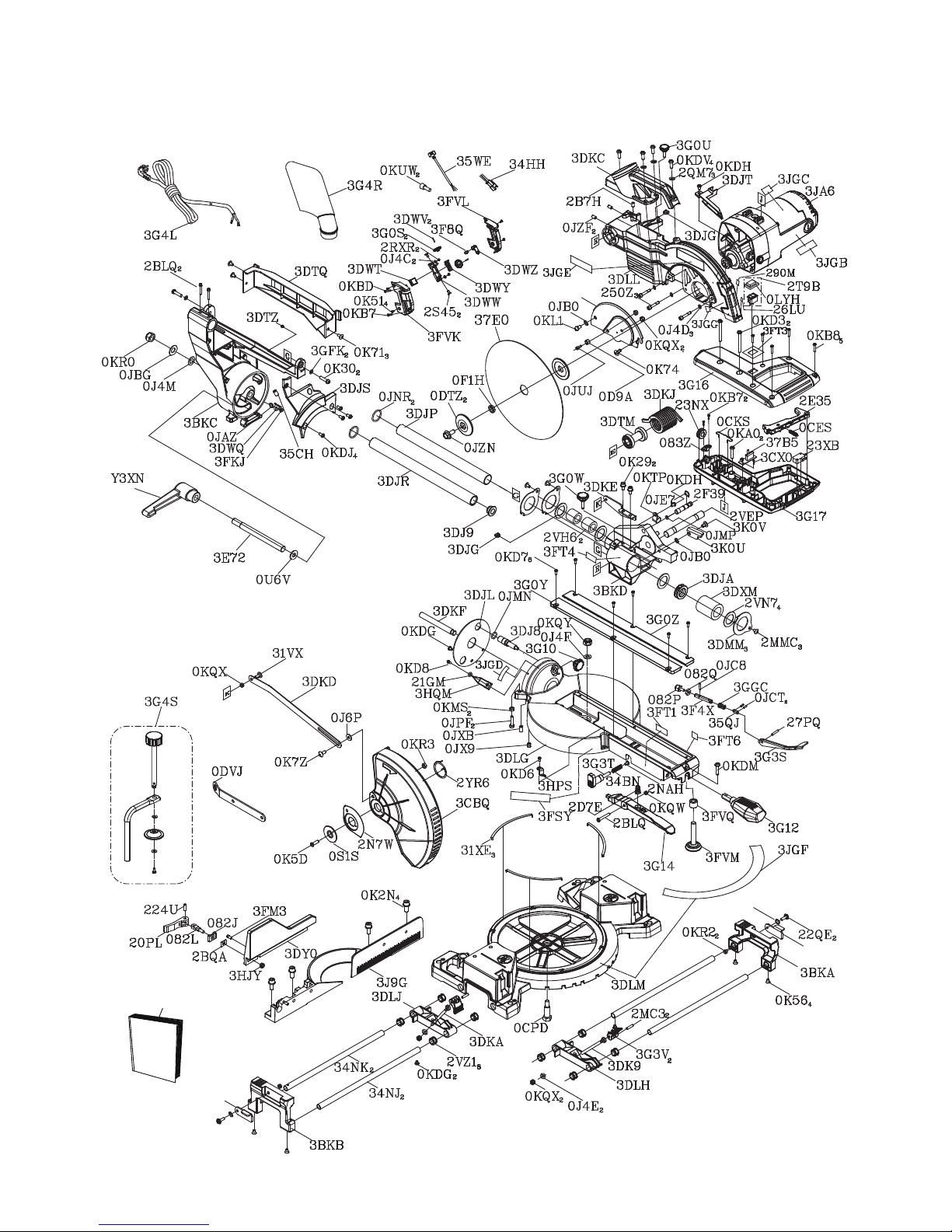
I.D. No. Description Size Q’ty I.D. No. Description Size Q’ty
082J CUSHION 1 0KD8 CR. RE. PAN HD. SCREW M4*0.7-12 1
082L BOLT 1 0KDG CR. RE. PAN HD. SCREW M5*0.8-6 3
082P SCREW STOP 1 0KDH CR. RE. PAN HD. SCREW M5*0.8-8 2
082Q LOCK NUT 1 0KDJ CR. RE. PAN HD. SCREW M5*0.8-12 4
083Z CORD CLAMP 1 0KDM CR. RE. PAN HD. SCREW M5*0.8-20 1
0CES COMPRESSION SPRING 1 0KDV CR. RE. PAN HD. SCREW M6*1.0-16 4
0CKS SPRING WIRE 1 0KL1
CR. RE. PAN HD. ROUND NECK SCREW
M6*1.0-12 1
0CPD CENTER BOLT 1 0KMS HEX. NUT M6*1.0 T=5 2
0D9A ANCHOR BLOCK 1 0KQW LOCK NUT M5*0.8 T=5 1
0DTZ ARBOR COLLAR 2 0KQX NUT M6*1.0 T=6 5
0DVJ BLADE WRENCH 1 0KQY LOCK NUT M8*1.25 T=8 1
0F1H COLLAR 1 0KR0 NUT
M12*1.75 T=12
1
0J4C FLAT WASHER φ4*8-1 2 0KR2 LUCK NUT M5*0.8 T=5 2
0J4D FLAT WASHER φ5*10-1 3 0KR3 LOCK NUT M6*1.0 T=6 1
0J4E FLAT WASHER φ6*13-1 2 0KTP CABLE CLAMP 1
0J4F FLAT WASHER φ8*16-2.5 1 0KUW TERMINAL 2
0J4M FLAT WASHER φ12*21-1 1 0LYH DUST GUARD 1
0J6P FLAT WASHER φ6*16-2 1 0S1S COLLAR 1
0JAZ WAVE WASHER WW-6 3 0U6V FLAT WASHER φ10*25-3 1
0JB0 WAVE WASHER WW-8 2 20PL CLAMP HANDLE 1
0JBG DISC SPRING WASHER φ12 1 21GM FLAT WASHER φ4*10-1 1
0JC8 SPRING PIN 1 224U ROLL PIN 1
0JCT SPRING PIN 2 22QE
CR. RE. ROUND WASHER HD. SCREW
M5*0.8-16 2
0JE7 C-RING 1 23NX CORD GUARD 1
0JMN O-RING 1 23XB LIMIT SWITCH 1
0JMP O-RING 1 250Z HEX. SOC. HD. CAP SCREW M5*0.8-35 3
0JNR O-RING ROD 2 26LU WARNING LABEL 1
0JPF HEX. HD. BOLT M6*1.0-25 2 27PQ ROLL PIN 1
0JUJ HEX. SOC. HD. CAP BOLT M6*1.0-12 1 290M CAUTION LABEL 1
0JX9 HEX. SOC. SET SCREW M6*1.0-10 1 2B7H HEX. SOC. SET SCREW M6*1.0-12 1
0JXB HEX. SOC. SET SCREW M6*1.0-16 1 2BLQ HEX. SOC. HD. CAP SCREW M5*0.8-40 3
0JZF HEX. SOC. SET SCREW M6*1.0-10 2 2BQA BLADE HOLDER 1
0JZN ARBOR BOLT M8*1.25-20 1 2D7E COMPRESSION SPRING 1
0K29 HEX. SOC. HD. CAP SCREW M6*1.0-12 2 2E35 TRIGGER 1
0K2N HEX. SOC. HD. CAP SCREW M8*1.25-25 4 2F39 CLEVIS PIN 1
0K30 HEX. SOC. TRUSS HEAD & WASHER M6*1.0-16 2 2MC3 ROLL PIN 2
0K51 CR. RE. COUNT HD. SCREW M4*0.7-8 4 2MMC CR. RE. TRUSS HD. SCREW M5*0.8-6 3
0K56 CR. RE. COUNT HD. SCREW M5*0.8-12 4 2N7W BRACING PLATE 1
0K5D CR. RE. COUNT HD. SCREW M6*1.0-20 1 2NAH CR. RE. TRUSS HD. SCREW M4*0.7-8 1
0K71 CR. RE. TRUSS HD. SCREW M5*0.8-8 3 2QM7 FLAT WASHER φ6*10-1 3
0K74 CR. RE. TRUSS HD. SCREW M6*1.0-8 1 2RXR CR. RE. PAN HD. SCREW M4*0.7-8 2
0K7Z
CR. RE. TRUSS HD. ROUND NECK SCREW
M6*1.0-14 1 2S45 CR. RE. COUNT HD. SCREW M3*0.5-6 2
0KA0 CR. RE. PAN HD. TAPPING SCREW M5*12-20 2 2T9B ROCK SWITCH ASS’Y 1
0KB7 CR. RE. PAN HD. TAPPING SCREW M4*18-16 3 2VEP SHAFT 1
0KB8 CR. RE. PAN HD. TAPPING SCREW M4*18-20 5 2VH6 LINEAR MOTION BEARING 2
0KBD CR. RE. PAN HD. TAPPING SCREW M4*18-25 1 2VN7 BLANKET WASHER φ25*φ38 4
0KD3 CR. RE. PAN HD. SCREW M6*1.0-50 2 2VZ1 RUBBER INSERT 8
0KD6 CR. RE. PAN HD. SCREW M4*0.7-8 1 2YR6 SPRING GUARD 1
0KD7 CR. RE. PAN HD. SCREW M4*0.7-10 6 31VX
CR. RE. TRUSS HD. ROUND NECK SCREW
M6*1.0-14 1
ORDER ONLY BY MODEL NUMBER AND PART NUMBER
SM2509R PARTS LIST (A)

24
I.D. No. Description Size Q’ty I.D. No. Description Size Q’ty
31XE SLIDE PLATE 3 3F4X SHAFT 1
34BN COMPRESSION SPRING 1 3F8Q PLUNGER HOUSING 1
34HH LEAD WIRE ASS’Y 1 3FKJ
CR. RE. TRUSS HD. ROUND NECK SCREW
M5*0.8-12 1
34NJ UPPER TUBE 2 3FM3 SPECIAL BOLT 1
34NK UPPER TUBE 2 3FSY WARNING LABEL 1
35CH HEX. SOC. SET SCREW M6*1.0-16 1 3FT1 CAUTION LABEL 1
35QJ LEVER 1 3FT3 CAUTION STICKER 1
35WE LEAD WIRE ASS’Y 1 3FT4 WARNING LABEL 1
37B5 CONTROLLER ASS’Y 1 3FT6 CAUTION LABEL 1
37E0 BLADE 1 3FVK LASER COVER 1
3BKA EXTENSION WING (RIGHT) 1 3FVL LASER COVER 1
3BKB EXTENSION WING (LEFT) 1 3FVM LEVELING PAD 1
3BKC MITER ARM 1 3FVQ ADJUSTABLE NUT 1
3BKD SLIDE-BAR SEAT (FRONT) 1 3G0S BUTTON 2
3CBQ PC-GUARD 1 3G0U CLAMP BOLT 1
3CX0 CR. RE. PAN HD. TAPPING SCREW M3*24-8 1 3G0W CLAMP BOLT 1
3DJ8 LOCATING BAR 1 3G0Y TABLE INSERT 1
3DJ9 FRAME END CAP 1 3G0Z TABLE INSERT 1
3DJA BEARING WASHER 1 3G10 KNOB-HANDLE 1
3DJG SPACER 2 3G12 LOCKING HANDLE ASS’Y 1
3DJL SET PLATE 1 3G14 PLUNGER HANDLE 1
3DJP MITER BAR ASS’Y 1 3G16 MOTOR HANDLE 1
3DJR MITER BAR 1 3G17 MOTOR HANDLE 1
3DJS MITER ARM COVER 1 3G3S KNOB 1
3DJT CABLE SHIELD 1 3G3T PLUNGER HANDLE 1
3DK9 BOLT 1 3G3V CLAMP HANDLE 2
3DKA BOLT 1 3G4L POWER CABLE 1
3DKC SEGMENT HANDLE 1 3G4R DUST BAG ASS’Y 1
3DKD LEVER 1 3G4S VISE ASS’Y 1
3DKE LEVER BRACKET 1 3GFK FLAT WASHER φ6*12-1 2
3DKF PIVOT SHAFT 1 3GGC COMPRESSION SPRING 1
3DKJ TORSION SPRING 1 3HJY LOCK NUT M6*1.0 T=9 1
3DLG TABLE 1 3HPS NEEDLE POINTER 1
3DLH FOLLOWER PLATE (RIGHT) 1 3HQM NEEDLE POINTER 1
3DLJ FOLLOWER PLATE (LEFT) 1 3J9G FENCE 1
3DLL ARM 1 3JA6 MOTOR ASS’Y 1
3DLM BASE 1 3JGB TRADEMARK LABEL 1
3DMM BEARING COVER 3 3JGC LABEL 1
3DTM SHAFT SLEEVE 1 3JGD TILTING SCALE 1
3DTQ POWER CORD CLAMP 1 3JGE TRADEMARK LABEL 1
3DTZ RUBBER PAD 1 3JGF SCALE 1
3DWQ PLATE 1 3JGG CAUTION LABEL 1
3DWT INSERT 1 3JQE PLATE (RIGHT) 1
3DWV PIN 2 3JQF PLATE (LEFT) 1
3DWW LASER SET 1 3K0U ANCHOR PLATE 1
3DWY PIVOT-SUPPORT 1 3K0V
CR. RE. TRUSS HD. ROUND NECK SCREW
M6*1.0-10 1
3DWZ LASER PLUNGER HOUSING 1 3Q0A CUTTER SHAFT GUARD 1
3DXM LINEAR MOTION BEARING 1 3RNC INSTRUCTION MANUAL 1
3DY0 ASSIST FENCE 1 Y3XN CLAMP HANDLE 1
3E72 SPECIAL BOLT 1
ORDER ONLY BY MODEL NUMBER AND PART NUMBER
SM2509R PARTS LIST (B)
25
Schematic MODEL: SM2509R
3RNC
3Q0A
3JQE
3JQF
0JAZ
2

26
ORDER ONLY BY MODEL NUMBER AND PART NUMBER
SM2509R MOTOR PARTS LIST
I.D. No. Description Size Q’ty
0HX9 NEEDLE BEARING 1
0JCD SPRING PIN 1
0K43 CR. RE. PAN HD. SCREW & WASHER M5*0.8-16 2
0K44 CR. RE. PAN HD. SCREW & WASHER M5*0.8-12 1
0KBC CR. RE. PAN HD. TAPPING SCREW M5*16-25 2
0KCP CR. RE. PAN HEAD TAPPING & WASHER SCREW M5*12-60 2
0QGR COMPRESSION SPRING 1
0QM2 BRUSH HOLDER ASS’Y 2
0QQU CARBON BRUSH ASS’Y 2
0QR0 BRUSH COVER 2
2DW9 WAVE WASHER BWW-608 1
2VGY GEAR BOX 1
2VP2 MOTOR COVER 1
2VPU FLOW GUIDE 1
3236 CR. RE. PAN HD. SCREW & WASHER M6*1.0-55 4
32GU CUTTER SHAFT ASS’Y 1
3712 ARMATURE ASS’Y 1
37J5 LEAD WIRE ASS’Y 1
3G4H BRACKET STOP ASS’Y 1
3G4N FIELD ASS’Y 1
3HLH HEX. SOC. SET SCREW M5*0.8-6 2
3JD2 MOTOR REAR COVER 1

27
NOTES

28
NOTES

29
®
 Loading...